Lession 5 DC choppers.ppt is for understanding voltage reulators
1.
Two types
Step down: the output voltage is less
than the input voltage
Step Up : the output voltage is greater
than the input voltage
dc to dc converter ( DC choppers)
It is a variable voltage
dc source obtained from
a fixed voltage dc
source.
Some uses of dc chopper :
•Traction motor control
•Regenerating braking
•Voltage regulators
2.
Step Down DC
choppers
VS
Choppe
r
VS
t
VS
VO
t
RVO
VS
t1 t2
T
The output dc
voltage is given by
1
t
0
S
O dt
V
T
1
V
S
1
O V
T
t
V
T
t
K 1
Is known as
duty cycle
S
O KV
V
The output dc voltage can be controlled by varying
K
t1 t2
t1 t2
VBE
t
3.
VO
t
VS
t1 t2
T
The outputdc voltage
can be controlled by
varying K
Step Down DC
choppers Two types:
1. Constant frequency operation
: The chopping period T is kept
constant whereas the ON time
t1 is varied. Thus the width of
the pulse is varied and such
control is known as Pulse width
modulation (PWM) control.
2. Variable frequency operation :
The chopping period T is varied
whereas either the ON time t1 or
the OFF time t2 is kept constant.
This is known as frequency
modulation.
VO
t
VS
t1 t2
T
VO
t
VS
t1 t2
T
VO
t
VS
t1 t2
T
4.
Step Down DCchoppers : RL LOAD
VS
t
VS
VO
t
t1
VS
t2
T
VBE
t
VO
VS
Choppe
r
R
L
E
V
E
dt
di
L
Ri
t
L
R
t
L
R
e
R
E
V
e
I
t
i 1
)
( 1
i
t
I1
I2
For static RL
load, E=0
For DC motor
load, E=Back emf
During time t1 Chopper is
ON
Solving
,
Diode is OFF
5.
Step Down DCchoppers : RL LOAD
VS
t
VS
VO
t
t1
VS
t2
T
VBE
t
VO
VS
Choppe
r
R
L
E
0
E
dt
di
L
Ri
i
t
I1
I2
During time t2 Chopper in OFF
Solving
,
Diode is ON
t
L
R
t
L
R
e
R
E
e
I
t
i 1
)
( 2
6.
Step Down DCchoppers : RL LOAD
VS
t
VS
t1 t2
T
i
t
I1
I2
During time t2
t
L
R
t
L
R
e
R
E
e
I
t
i 1
)
( 2
During time t1
1
2
2
2
2
1
)
( I
e
R
E
e
I
t
i
t
L
R
t
L
R
t
t
t
L
R
t
L
R
e
R
E
V
e
I
t
i 1
)
( 1
2
1
1
1
1
1
)
( I
e
R
E
V
e
I
t
i
t
L
R
t
L
R
t
t
7.
Step Down DCchoppers : RL LOAD
2
2
1
2
1
t
L
R
t
L
R
e
R
E
e
I
I
1
1
1
1
2
t
L
R
t
L
R
e
R
E
V
e
I
I
Solving
,
R
E
e
e
R
V
I
T
t
t
L
R
1
1
1
1
1
R
E
e
e
R
V
I
T
t
t
L
R
1
1
1
1
2
R
E
e
e
R
V
I K
KT
L
R
1
1
1
R
E
e
e
R
V
I K
KT
L
R
1
1
2
8.
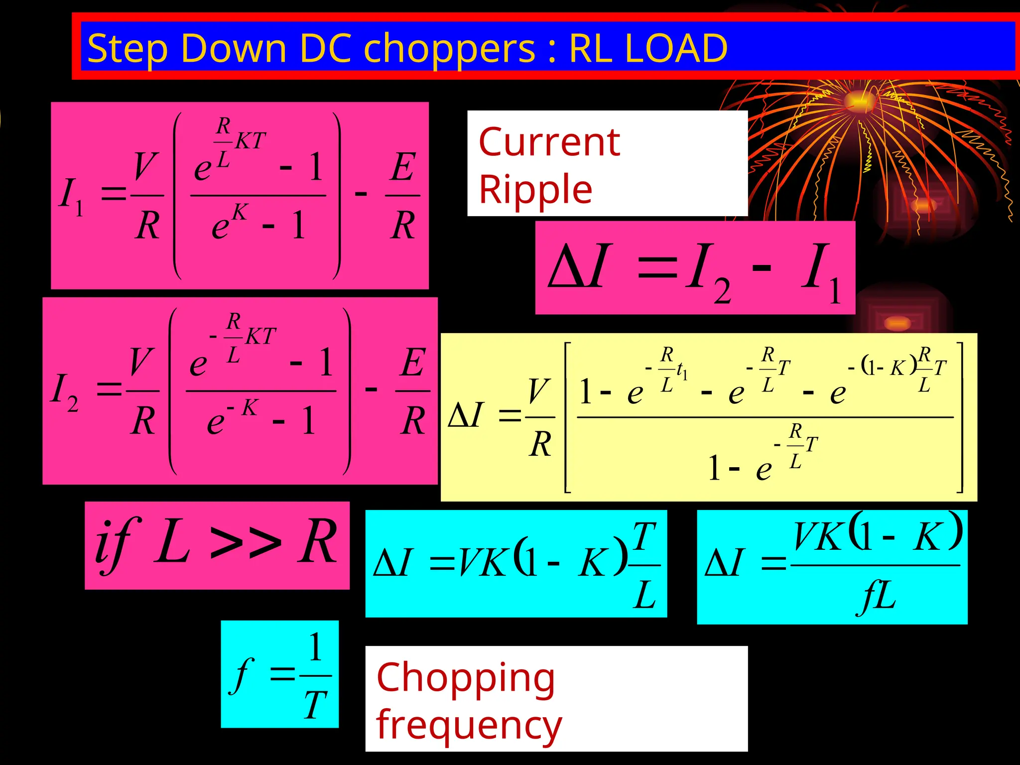
Step Down DCchoppers : RL LOAD
R
E
e
e
R
V
I K
KT
L
R
1
1
1
R
E
e
e
R
V
I K
KT
L
R
1
1
2
Current
Ripple
1
2 I
I
I
T
L
R
T
L
R
K
T
L
R
t
L
R
e
e
e
e
R
V
I
1
1
1
1
R
L
if
L
T
K
VK
I
1
fL
K
VK
I
1
T
f
1
Chopping
frequency
9.
Step Up DCchoppers
VS
Choppe
r
R VO
L D1
C
i
t
t1 t2
I2
I1
i
For the period t1 chopper is ON
and energy is stored in the
inductor, so the inductor current is
increasing.
For the period t2 chopper is OFF and
energy is released from the inductor,
so the inductor current is decreasing.
When the chopper is ON, voltage across the inductor is given
by
S
V
L
dt
di
S
1
V
t
ΔI
L
L
t
V
ΔI 1
S
When the chopper is OFF, the output voltage is given by
2
S
t
ΔI
L
V
O
v
2
1
S
S
t
t
V
V
O
v
10.
Step Up DCchoppers
VS
Choppe
r
R VO
L D1
i
i
t
t1 t2
I2
I1
T
v0
t
t1 t2
VS
2
t
ΔI
L
The output voltage is given
by
2
S
O
t
ΔI
L
V
V
2
1
S
S
O
t
t
V
V
V
2
1
S
O
t
t
1
V
V
2
2
1
S
O
t
t
t
V
V
1
S
O
t
-
T
T
V
V
T
t
-
1
1
V
V
1
S
O
K
-
1
1
V
V S
O
11.
Voltage
Regulators
It converts unregulatedvoltages to regulated
voltage
Dc chopper
Variable K
unregulate
d dc
voltage
regulated
dc voltage
A dc chopper can be used as a
regulator
-
+
Vr
12.
Switch Mode Regulators
BuckRegulator:
Basically step down
chopper, the output voltage
is less than the input
voltage.
Boost Regulator:
Basically step up chopper,
the output voltage is greater
than the input voltage.
Buck-Boost Regulator:
The output voltage may less
than or more than the input
voltage based on inductor
energy transfer..
Cuk Regulator:
The output voltage may be
less than or more than the
input voltage, based on
capacitor energy transfer.
13.
VS
Choppe
r R
L
C
VO
Buck Regulator:
Basicallystep down chopper, the output voltage is less than the input
voltage.
i
t
t1 t2
I2
I1
dt
di
L
V
V o
s
1
o
s
t
ΔI
L
V
V
1
o
s
t
L
V
V
I
2
o
t
ΔI
L
V 2
o
t
L
V
I
1
o
s
2
o
t
L
V
V
t
L
V
I
14.
VS
Choppe
r
R
L
C
K
VO
Buck Regulator:
Basically stepdown chopper, the output voltage is less than the input
voltage.
i
t
t1 t2
I2
I1
1
o
s
2
o
t
L
V
V
t
L
V
I
KT
t1
T
K
1
t2
s
1
s
o KV
T
t
V
V
15.
Buck Regulator:
Basically stepdown chopper, the output voltage is less than the input
voltage.
1
o
s
t
L
V
V
I
2
o
t
L
V
I
o
s
1
V
V
IL
t
o
2
V
IL
t
o
S
o
2
1
V
-
V
IL
V
IL
t
t
f
1
T
16.
Buck Regulator: Ripplecurrent
o
S
o
2
1
V
-
V
IL
V
IL
t
t
f
1
T
fL
K
1
K
V
ΔI S
17.
Numerical
Example
S
o KV
V
Abuck regulator has input voltage 12V. The required
load voltage is 5V. The ripple current is 0.8 A. If the
chopping frequency is 25kHz, Calculate the value of
the inductor.
%
67
.
41
12
5
S
o
V
V
K
fL
K
1
K
V
ΔI S
I
f
K
1
K
V
L S
0.8
*
25000
.41)
-
.41(1
*
12
L H
83
.
145
VS Choppe
r
Cuk Regulator
load
Chopperif OFF, L1 and C1 is charged through
diode
C1
C2
L1 L2
Chopper if ON, L1 is charged through
chopper
C1 is discharged through chopper and charging C2 and
L2.
Also current flows through load but in opposite direction
K
1
KV
V s
o