Construction drawings
•
1 like•964 views

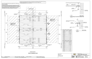
This document provides details for roof framing and sheeting installation, including: 1. Clip mark numbers for anti-roll clips and their locations on the roof plan. Roof system uses anti-roll clips installed as shown in section RF50/AA (uphill) or bolts. 2. Building code specifies considering snow surcharges for lower roofs within 20 feet of a higher structure, but supplied information does not indicate a shadowing structure so snow surcharges were not considered. 3. Sections and details show purlin to rafter connections, typical strap plate between purlins, and roof sheeting plan with eave strut line locations.

Recommended
More Related Content
Similar to Construction drawings
Similar to Construction drawings (15)
More from Dongze Di (6)
Construction drawings
- 1. CLIP MARK NUMBERS ARE CL-12, CL-13, OR CL-14. RF50/AAA (downhill) AND RF51/BA. LOCATIONS ARE INDICATED ON ROOF FRAMING PLAN. THIS ROOF SYSTEM DESIGN USED ANTI-ROLL CLIPS INSTALLED AS SHOWN IN SECTION RF50/ AA (uphill) OR BOLTS UNLESS NOTED. (2) 1/2 X 1 1/4 A325T NOTE: TYPICAL PURLIN/GIRT BOLTED CONNECTION TO FLANGE USE WOOD STRUCTURE WOOD STRUCTURE GALBED 50'X42'X10' EH=10'0 LOWER BUILDING BUILDING CODE SPECIFICATIONS REQUIRE CONSIDERATION OF SNOW SURCHARGES FOR ANY LOWER ROOF OF A STRUCTURE LOCATED WITHIN 20 FT. OF A HIGHER STRUCTURE. INFORMATION SUPPLIED TO THE METAL BUILDING SUPPLIER DOES NOT INDICATE PRESENCE OF A SHADOWING STRUCTURE WITHIN THIS 20 FT. ENVELOPE, AND AS SUCH, SNOW SURCHARGES HAVE NOT BEEN CONSIDERED IN THE DESIGN. WOOD STRUCTURE GALBED 50'X24'X10' EH=10'0 LOWER BUILDING 1'-0OVERHANG 1'-0OVERHANG 80Z16-5 (U.N.) (7) REQUIRED 80Z16-4 (U.N.) (7) REQUIRED 3'-0 - 3'-0 LAP TYP U.N. SBC-1 SBC-1 8" MASONRY WALL NOT BY ABC CL-12 CL-12 CL-12 CL-12 CL-12 CL-12 CL-12 CL-12 D 1'-0OVERHANG50'-0 16'-816'-816'-8 A C B 1'-0OVERHANG 1'-0 24'-0 24'-0 1'-0 27'-4780Z16-5 A E-05 SBC-1 8" MASONRY WALL NOT BY ABC 50'-0 PLANE ID: 1005, 1004 321 3'-0 - 3'-0 LAP TYP U.N. OHBL OHBL 80Z16-6 80Z16-6 80Z16-7CL-12 CL-12 CL-12 CL-12 CL-12 CL-12 CL-12 CL-12 CL-12 80Z16-7 80Z16-4 (U.N.) (7) REQUIRED 1B80C2-1 BR5-2 BR5-4 BR5-3 OHBL BR5-5 80Z16-1 80Z16-6 80Z16-6 80Z16-6 EAVE STRUT LINE (SEE S.W.) BR5-3 BR5-4 80Z16-6 BR5-3 BR5-4 BR5-2 BR5-3 BR5-4 80Z16-7 80Z16-7 OHBL 1B80C2-4 BR5-5 80Z16-7 80Z16-7 80Z16-7 80Z16-7 80Z16-3 80Z16-5 (U.N.) (7) REQUIRED CL-12 80Z16-7 80Z16-2 80Z16-7 80Z16-7 80Z16-7 1B80C2-3 CL-12 CL-12 80Z16-6 80Z16-6 80Z16-6 80Z16-6 80Z16-6 80Z16-6 EAVE STRUT LINE (SEE S.W.) 80Z16-1 B E-05 CL-12 CL-12 SBC-1 1B80C2-2 CL-12 CL-12 26'-31BR5-5 26'-112BR5-4 25'-32BR5-3 26'-61BR5-2 27'-4680Z16-7 27'-4680Z16-6 50'-0 16'-8 PART LENGTH CHART(ID: 1004) 26'-31BR5-5 26'-112BR5-4 25'-32BR5-3 26'-61BR5-2 27'-4680Z16-7 27'-4680Z16-6 27'-4780Z16-5 27'-4780Z16-4 24'-0 5/8180Z16-3 24'-0 5/8180Z16-1 24'-11 3/411B80C2-4 24'-11 3/411B80C2-2 LENGTHQTYMARK PART LENGTH CHART(ID: 1005) D A C B 16'-8 80Z16-4 80Z16-2 80Z16-1 1B80C2-3 1B80C2-1 MARK 16'-8 27'-47 24'-0 5/81 24'-0 5/81 24'-11 3/41 24'-11 3/41 LENGTHQTY 50'-0 1'-0 24'-0 24'-0 1'-0 321 STRAP PLATE BETWEEN PURLINS (NOT BY ABC) A E-05 SECTION 8" MASONRY (NOT BY ABC) EMBED PLATE (NOT BY ABC) ENDWALL RAFTER ER- CHANNEL SBC-(C8X11.5) 8" MASONRY (NOT BY ABC) (2)1/2X1 1/4A325T PURLIN BOLTS ENDWALL RAFTER ER- CHANNEL SBC-(C8X11.5) 80Z16- PURLIN NO DWN: / CKD: ENGR DATERELEASE / REVISION NO RELEASE / REVISION DWN: / CKD: ENGR DATE 1 DD / MDB 10/21/2015SMFOR CONSTRUCTION 0 DAW / DAW 09/29/2015SMPERMITS SHEET: M15C0488A E-05 BLACK SWAMP STEEL MILLER GYM 22494 C. R. 8 DRAWING STATUS: FOR CONSTRUCTION JOB NUMBER: DESIGN: MSA 46.0 BIM: 20CSOFTWARE VERSIONSARCHBOLD, OH 43502 ROOF FRAMING PLAN PURLIN TO RAFTER CONNECTION B E-05 SECTION
- 2. BOLTS UNLESS NOTED. (2) 1/2 X 1 1/4 A325T NOTE: TYPICAL PURLIN/GIRT BOLTED CONNECTION TO FLANGE USE CLIP MARK NUMBERS ARE CL-12, CL-13, OR CL-14. RF50/AAA (downhill) AND RF51/BA. LOCATIONS ARE INDICATED ON ROOF FRAMING PLAN. THIS ROOF SYSTEM DESIGN USED ANTI-ROLL CLIPS INSTALLED AS SHOWN IN SECTION RF50/ AA (uphill) OR WOOD STRUCTURE WOOD STRUCTURE GALBED 50'X24'X10' EH=10'0 LOWER BUILDING BUILDING CODE SPECIFICATIONS REQUIRE CONSIDERATION OF SNOW SURCHARGES FOR ANY LOWER ROOF OF A STRUCTURE LOCATED WITHIN 20 FT. OF A HIGHER STRUCTURE. INFORMATION SUPPLIED TO THE METAL BUILDING SUPPLIER DOES NOT INDICATE PRESENCE OF A SHADOWING STRUCTURE WITHIN THIS 20 FT. ENVELOPE, AND AS SUCH, SNOW SURCHARGES HAVE NOT BEEN CONSIDERED IN THE DESIGN. NO DWN: / CKD: ENGR DATERELEASE / REVISION NO RELEASE / REVISION DWN: / CKD: ENGR DATE 1 DD / MDB 10/21/2015SMFOR CONSTRUCTION 0 DAW / DAW 09/29/2015SMPERMITS SHEET: M15C0488A E-06 BLACK SWAMP STEEL MILLER GYM 22494 C. R. 8 DRAWING STATUS: FOR CONSTRUCTION JOB NUMBER: DESIGN: MSA 46.0 BIM: 20CSOFTWARE VERSIONSARCHBOLD, OH 43502 ROOF STRAPING PLAN TYP. FROM FL. 5'-0 1/24'-10 5/165'-0 1'-0OVERHANG1'-0OVERHANG50'-0 16'-8 50'-0 16'-8 50'-0 24'-0 50'-0 24'-0 16'-8 8" MASONRY WALL NOT BY ABC 1'-0OVERHANG A 16'-8 WOOD STRUCTURE GALBED 50'X42'X10' 6:12 EH=10'0 LOWER BUILDING C B 1 1'-0 1'-0OVERHANG D 1'-0 1 16'-8 24'-0 PLANE ID: 1005, 1004 2 EAVE STRUT LINE (SEE S.W.) A 3 1'-0 16'-8 B C 24'-0 EAVE STRUT LINE (SEE S.W.) 2 1'-0 8" MASONRY WALL NOT BY ABC D 3
- 3. REQUIRED FASTENER LAYOUT DETAILS. ALL WALL PANELS MUST BE FASTENED TO ALL GIRTS (PARTIAL BAY OR FULL BAY) ACCORDING TO THE ERECTION NOTE!!! CROSS SECTION AT THIS FRAME LINE FOR THE REQUIRED CROSS BRACING. THIS ENDWALL FRAME MUST NOT BE ERECTED WITHOUT THE CROSS BRACING. REFER TO THE FRAME FIELD SLOT GIRTS AS REQUIRED FOR DIAGONAL BRACING. ERECTION NOTE!!! NOTE: JAMB EXTENSION WAS PROVIDED (FIELD WORK IF JAMB EXTENSION ARE REQUIRED). JAMB EXTENSION MARK NO.: 80C14-2, 80C14-4, 80C14-7, 80C14-8. NOTE: GA-1 WAS PROVIDED FOR RAKE LINER. USE WHEN LINER PANELS INTERFERE WITH THE RAFTER (ACCORDING TO DETAIL A). REFER TO DETAIL LP07AB ONCE THE LINER IS CLEAR OF THE RAFTER. THE INTERFERENCE IS MINIMAL AND MAY BE ABLE TO BOW THE PANELS AROUND THE FLANGE. IF SO, FLASH WITH PF95 PARTITION FLASHING AS SHOWN IN LP22AA & LP23AB. NO DWN: / CKD: ENGR DATERELEASE / REVISION NO RELEASE / REVISION DWN: / CKD: ENGR DATE 0 DD / JSM 09/30/2015MJDFOR CONSTRUCTION SHEET: M15G0440A E-07 JANS CORPORATION SOUTHEASTERN ELECTRIC 605 SD HIGHWAY 11 DRAWING STATUS: FOR CONSTRUCTION JOB NUMBER: DESIGN: MSA 44.0 BIM: 20CSOFTWARE VERSIONSALCESTER, SD 57001 OVERHEAD DOOR TYPE 16'-21BR5-3 15'-10 2'-10 3'-4 NOTE: USE #12X2 SDHH AT WALL PANEL ATTACHMENT LOCATIONS. CC2 (TYP) CLV1-2 CLV1-2 CLV1-2 CLV1-2 ER2 80Z16-5 BR5-2 4'-5 13/16180Z16-5 9'-5 13/16180Z16-4 10'-5 13/16180Z16-3 13'-2 1/2180Z16-2 18'-2 1/2280Z16-1 13'-2 1/2180Z15-1 15'-5 13/16180Z12-1 3'-0280C14-10 10'-4180C14-9 1'-10 5/16180C14-8 2'-4 5/16180C14-7 2'-8 13/16180C14-4 11'-1 1/2280C14-3 2'-5 1/2180C14-2 11'-1 1/2280C14-1 LENGTHQTYMARK PART LENGTH CHART 17'-111 13'-0 3'-64'-04'-0 1'-0 34'-0 19'-6 PLANE ID: 1002 12C12-1 12C12-1 EI1 AC B CL-4 (TYP) GEA-6 (TYP) 80Z16-1 (U.N.) (2) REQUIRED 80Z16-1 (U.N.) (2) REQUIRED 80C14-9 1 80C14-3 80C14-3 80Z12-1 80Z16-4 EC2 GEA-6 (TYP) CL-4 (TYP) 14'-6 80Z16-5 (U.N.) (1) REQUIRED 80Z16-5 (U.N.) (1) REQUIRED 80C14-10 80Z15-1 CL-4 (TYP) GEA-6 (TYP) 2 80C14-1 80C14-1 80Z16-3 80Z16-2 ER1 80C14-10 12C12-1 EC1 CC2 (TYP) CL-4 (TYP) GEA-6 (TYP) 4'-44'-63'-02 9'-210'-41 SILL HEIGHTHEIGHTWIDTHMARK FRAMED OPENING TABLE (1)GE1R (1)TCB2R (1)TRUECR A E-07 USE FL18 AT COLUMNS REFER TO SED LP42R/AB ENDWALL SHEETING ELEVATION AT LINE 1 15'-10 13'-02'-10 1/2 11/21/2 FRAMED OPENING TABLE 3'-02 10'-41 WIDTHMARK (1)FCR (1)GE1L (1)TCB2L (1)TRUECL 34'-0 17'-0 SHEETING PACKAGE: SP1014(SUBG) PLANE ID: 1002 (0.2)FSJ1 (1)FDH2-3.7 (1)FOCF80-3.6 (1)FOHF80-3.6 (2)FJ15-7.4 (2)FOCF80-6.6 4'-6 (1)FDH2-10.7 (1)FOCF80-12.6 (2)FJ15-10.4 (2)FOCF80-10.6 OVERHEAD DOOR9'-2 TRIMTYPEHEIGHT 17'-0 C 1 L3P24-7(16'-11/8) L3P24-6(15'-71/8) L3P24-5(15'-11/8) L3P24-4(14'-71/8) L3P24-3(14'-11/8) L3P24-2(13'-71/8) (0.5)80C16-240N (0.6)VFF7 (1)80C16-240N (1.2)VFF7 A 2 L3P24-13(13'-73/8) L3P24-12(13'-93/8) L3P24-11(14'-33/8) L3P24-10(14'-93/8) L3P24-9(15'-33/8) L3P24-8(15'-93/8) 2'-0 (1)FCR (1)TRCU2-ABC (1)TRPBB2 (1)TRESSL (1)TRESSR (2)TRAC (1.2)TRU1 (0.058)FEB-10.2 (1)GA-1 (5)CL-21 (1)RSA-1 (1.2)RSF1 (1.2)FCP1 (1.2)TRU1 (0.058)FEB-10.2 (1)GA-1 (5)CL-21 (1)RSA-1 (1.2)RSF1 (1.2)FCP1 (0.8)LCF2 (1.75)GA-1 (2)FJ15-10.4 (0.4)LCF2 (2)FJ15-7.4 TRIM (1)FL3A0 ENDWALL LINER SHEEING ELEVATION AT LINE 1 13'-0 A E-07 34'-0 PLANE ID: 1002 (1.2)LCF2 (1)GA-1 (1)FL2V5 (2)PF95-7.8 (1)GA-2 A L3P29-1(13'-0) L3P29-1(13'-0) L3P29-1(13'-0) L3P29-1(13'-0) L3P29-1(13'-0) 1 (1)FL3A0 (1.2)LCF2 (1)GA-1 (1)FL2V5 (2)PF95-7.8 (1)GA-2 C L3P29-1(13'-0) L3P29-1(13'-0) L3P29-1(13'-0) L3P29-1(13'-0) 2 L3P29-1(13'-0) L3P29-1(13'-0) L3P29-1(13'-0) OVERHEAD DOOR9'-210'-42 4'-63'-01 TYPEHEIGHTWIDTHMARK FRAMED OPENING TABLE CL-3 CL-3 #12X1 1/4 SDHH #12X1 1/4 SDHH 12C12-1 JAMB EXTENSION JAMB 80Z16-5 80Z16-3 B E-07 ENDWALL FRAMING ELEVATION AT LINE 1 DETAILB E-07
- 4. NO DWN: / CKD: ENGR DATERELEASE / REVISION NO RELEASE / REVISION DWN: / CKD: ENGR DATE 0 DD / AW 09/09/2015MJDFor Construction SHEET: M15N0391A E-13 KELLER, INC. K 5 PROPERTIES LLC W914 COUNTY ROAD CE DRAWING STATUS: FOR CONSTRUCTION JOB NUMBER: DESIGN: MSA 44.0 BIM: 20CSOFTWARE VERSIONSBRODHEAD , WI 53520 (2)1/2X 1 1/4 A325T (2)1/2 X1 1/4A325T JAMB 80C12-1 JAMB 80C12-2 80Z16-5X (2)1/2X 1 1/4 A325T CL-3 PR1 HEADER 80C14-5 HEADER 80C14-5 CL-3 CL-3 1E80S2-1 (2)1/2X 1 1/4 BHB (2) 1/2X 1 1/4A325T (2)1/2 X1 1/4BHB A E-13 SECTION 80Z16-6 CONNECT TO COLUMN W/ CL-4 CLIP & GEA-6 (EACH END) REINFORCING GIRT 80Z16-5X JAMB 80C14-1 EAVE STRUT 1E80S2-3 ER1 HEADER 80C14-4 HEADER 80C14-4 (2) 1/2X 1 1/4BHB (2)1/2X1 1/4 A325T (2) 1/2X 1 1/4A325T JAMB CONNECTIONS B E-13 DOUBLE JAMB SECTION CL-3 JAMB 80C14-2 (2)1/2 X1 1/4 A325T (2) 1/2X 1 1/4BHB (2)1/2X1 1/4 A325T CL-3 CL-3 (2)1/2 X1 1/4A325T CL-3
- 5. BOLTS UNLESS NOTED. (1) 1/2 X 1 1/4 A325T, (1) 1/2 X 2 3/16 A449 DE NOTE: TYPICAL PURLIN/GIRT BOLTED CONNECTION TO FLANGE USE NOTE: 1. OPEN TO STUD WALL WITH HORIZONTAL WALL PANEL. 2. FLANGE BRACES FROM STUDS TO GIRTS 4'0 O.C. MAX. SEE DETAIL A ON E-15. 3. STUD WALL NOT TO PARAPET ROOF BY MORE THAN 2 INCHES. NO DWN: / CKD: ENGR DATERELEASE / REVISION NO RELEASE / REVISION DWN: / CKD: ENGR DATE 1 DD / MDB 08/21/2015MJDRELEASED FOR CONSTRUCTION 0 KEB / BJC 08/07/2015MJDRELEASED FOR PERMITS SHEET: M15P0383A E-12 WITWER CONSTRUCTION, INC SNELL INVESTMENT 3525 METRO DRIVE DRAWING STATUS: FOR CONSTRUCTION JOB NUMBER: DESIGN: MSA 44.0 BIM: 20CSOFTWARE VERSIONSFORT WAYNE, IN 46818 D E-12 A E-12 19'-8 18'-01'-8 7'-61'-63'-67'-2 29'-7 7/8 20'-7 3/4 29'-7 7/8 22'-8 29'-11 29'-11 22'-8 32'-11 32'-11 8'-7 1/2 LENGTH PART LENGTH CHART FRAMED OPENING TABLE 80'-0 20'-8 40'-0 ERC-4 80U2 -20'-8 5/16 B E-12 ERC-1 80U2 -18'-2 1/4ERC-3 80U2 -20'-7 11/16 ERC-2 80U2 -18'-2 1/4 CL18-1.6 5/8 CL18-1.6 5/8 29'-8 40'-0 G 1 80C16-4 80C16-4 80C14-10 80Z16-4 SPBM1 (C8X11.5 ) RC1 RR1 CL-2 (TYP) 80Z13-6 (U.N.) (1) REQUIRED PLANE ID: 1002 E C E-12 80Z16-12 1'-0 - 1'-0 LAP TYP U.N. 80C14-10 EI1 CL-4 4'01'0 80Z14-3 (U.N.) (1) REQUIRED 2 80C14-10 80C14-10 SPBM2 (C8X11.5 ) 29'-8 480C16-4 C 80Z16-5 1'-0 - 1'-0 LAP TYP U.N. 80C14-10 EI1 CL-4 1'04'0 80Z13-7 (U.N.) (1) REQUIRED 1 80C16-4 SPBM3 (C8X11.5 ) 1SPBM3 1SPBM2 1SPBM1 180Z16-12 180Z16-5 180Z16-4 180Z14-3 180Z13-7 180Z13-6 A CL-2 (TYP) A E-12 80C14-10 RC2 80C16-4 RR1 680C14-10 QTYMARK 9'-010'-02 9'-020'-01 HEIGHTWIDTHMARK 2'-9 TYPESILL HEIGHT (4) SDHHT5 (2) SDHHT5 CL-4 BRK2 RC1 SPBM1 ( C8X11.5 ) A E-12 SECTION (1) #12X 1 1/4 SDHH (1) #12X 1 1/4 SDHH PURLIN 80U2 CL-3 (2)1/2 X1 1/4A325T (2)1/2 X1 1/4A325T B E-12 SECTION (2)SDHHT5 SPBM- CL-4 EI- C E-12 SECTION (4)SDHHT5 (2)1/2X1 1/4A325T CL-4 ERC-3 80U2 -20'-7 11/16 REINFORCING GIRT 80Z16-19X NEED TO FILED NOTCH THE BACK LEG OF THE GIRT DETAILD E-12 (2)1/2X 1 1/4 A325T RC1 1E80S5-6 A E-15 ENDWALL FRAMING ELEVATION AT LINE 1
- 6. NO DWN: / CKD: ENGR DATERELEASE / REVISION NO RELEASE / REVISION DWN: / CKD: ENGR DATE 0 DD / CAK 08/05/2015CLMRELEASED FOR CONSTRUCTION SHEET: M15K0363A E-10 HUGHES BUILDERS, INC. MONTAGUE METAL PRODUCTS 4101 W. FRUITVAIL ROAD DRAWING STATUS: FOR CONSTRUCTION JOB NUMBER: DESIGN: MSA 44.0 BIM: 20CSOFTWARE VERSIONSMONTAGUE, MI 49437 (2) SDHHT5 DETAILB E-10 SPBM1 (C8X11.5 ) 80C14-1 (2) 1/2 X 1 1/4 A325T BOLTS CL-3 CLB-1 AA 80Z13-1 EI3 (2 )1/2 X 1 1/4 A325T BOLTS CL-4 SPBM1 ( C8X11.5 ) DETAILA E-10 CL-4 ( 2)SDHHT5 A - A (2 )1/2 X 1 1/4 A325T BOLTS CL-4 CL-4 80Z13-1 EI3 SPBM1 (C8X11.5 ) (2 )1/2 X 1 1/4 A325T BOLTS ( 2)1/2 X 1 1/4 A325T BOLTS CLB-1
- 7. CROSS SECTION AT THIS FRAME LINE FOR THE REQUIRED CROSS BRACING. THIS ENDWALL FRAME MUST NOT BE ERECTED WITHOUT THE CROSS BRACING. REFER TO THE FRAME BOLTS UNLESS NOTED. (1) 1/2 X 1 1/4 A325T, (1) 1/2 X 2 3/16 A449 DE NOTE: TYPICAL PURLIN/GIRT BOLTED CONNECTION TO FLANGE USE NO DWN: / CKD: ENGR DATERELEASE / REVISION NO RELEASE / REVISION DWN: / CKD: ENGR DATE 1 DD / SB 07/22/2015SMRELEASED FOR CONSTRUCTION 0 DAW / DAW 06/17/2015SMRELEASED FOR PERMITS SHEET: M15P0258A E-15 T&W CORPORATION GREATER LAFAYETTE CHINESE ALLIAN 3501 W. 250 N. DRAWING STATUS: FOR CONSTRUCTION JOB NUMBER: DESIGN: MSA 44.0 BIM: 20CSOFTWARE VERSIONSWEST LAFAYETTE, IN 47906 OHB1 3'-0 LENGTH FRAMED OPENING TABLE OVERHANG CL-2 (TYP) 27'-4 18'-98'-7 7'-63'-02'-25'-05'-04'-8 180Z14-1 180C16-1 180C14-14 480C14-8 180C14-7 180C14-6 180C14-5 480C14-4 480C14-3 QTYMARK 3'-43 19'-82 3'-41 WIDTHMARK 26'-0 100'-0 80Z16-7 (U.N.) (3) REQUIRED 10'-6 80C14-7 80C16-1 80Z14-1 ER7( W12X14 ) 7'-2 ENDWALL FRAMING ELEVATION AT LINE 6 BLDG 1 25'-0 CGC10 USE (6) #12X1 1/2 SDHHT5 FASTENERS FOR ATTACHMENT OF CL-3 TO HSS TUBE. (TYP.) 1 80C14-8 OH80-1 24'-0 LENGTH 380Z16-127'-2 1/2 27'-6380Z16-77'-2 1/2 18'-9 1/8180Z16-610'-4 1/2 25'-7 1/4180Z16-57'-2 1/2 5OH80-124'-3280Z16-37'-2 1/2 QTYMARKLENGTHQTYMARK PART LENGTH CHART 2'-84'-6 TYPESILL HEIGHTHEIGHT 1BR5-426'-9 1BR5-324'-3 280Z16-1810'-4 1/2 380Z16-173'-4 35'-8 34'-3 25'-0 27'-6 27'-0 SEE SHEET E-17 FOR CORNER GIRT CONNECTION EC3(W12X14) A 80C14-8 1 80C14-4 80C14-3 OH80-1 80Z16-3 (U.N.) (2) REQUIRED 80C14-8 80Z16-18 1 80C14-4 80C14-3 OH80-1 3'-4 80C14-8 80C14-4 OH80-1 EI5(W12X14) 1'-0 - 1'-0 LAP TYP U.N. C 1 FB-1 FB-1 80C14-3 80Z16-12 (U.N.) (3) REQUIRED 80C14-3 80Z16-5 ER4( W12X14 ) 80Z16-18 CGC10 ER5( W12X14 ) 25'-0 SBT-1000 (HSS8X6X 1/4) PLANE ID: 1003 EI6(W10X22) 1'-0 - 1'-0 LAP TYP U.N. F GC-1 E-15 FB-2 FB-2 80C14-4 80C14-5 80Z16-17 (U.N.) (3) REQUIRED 2 EI7(W10X22) 1'-6 - 1'-6 LAP TYP U.N. GC-2 E-15 3 FB-2 FB-2 OH80-1 80C14-6 80C14-14 H ER6( W12X26 ) CLV1-1 80U2-1X 80Z16-6 CL-15 CL-15 CL-15 GC-3 E-15 J CL-2 EC4(W10X22) 3'-0 OVERHANG OHB5 FUTURE BUILDING 58' W 31'4 EAVE HEIGHT 1:12 SLOPE EI6 CANOPY BRACKET 80Z16-5 SBT-1000 (HSS8X6X 1/4 ) (2) 1/2 X 1 1/4 A325T BOLTS (3 )3/4 X 2 A325T BOLTS DETAIL TUBE HEADER & GIRT CONNECTION TO CANOPY BEAM GC-1 E-15 EI7 (2) 1/2 X 1 1/4 A325T BOLTS (3)3/4 X 2 A325T BOLTS SBT-1000 (HSS8X6X 1/4) 80C16-1 DETAIL TUBE HEADER & "C" CONNECTION TO CANOPY BEAM GC-2 E-15 EC4 REFER TO GC-5 ON E-18 FOR GIRT CONNECTION DETAIL CGC10 (2)1/2 X 1 1/4 A325T BOLTS 80C16-1 80Z16-18 DETAIL "C" CONNECTION TO CANOPY BEAM GC-3 E-15
- 8. REQUIRED FASTENER LAYOUT DETAILS. ALL ROOF PANELS MUST BE FASTENED TO ALL PURLINS (PARTIAL BAY OR FULL BAY) ACCORDING TO THE ERECTION NOTE!!! CLIP MARK NUMBERS ARE CL-12, CL-13, OR CL-14. RF50/AAA (downhill) AND RF51/BA. LOCATIONS ARE INDICATED ON ROOF FRAMING PLAN. THIS ROOF SYSTEM DESIGN USED ANTI-ROLL CLIPS INSTALLED AS SHOWN IN SECTION RF50/ AA (uphill) OR NO DWN: / CKD: ENGR DATERELEASE / REVISION NO RELEASE / REVISION DWN: / CKD: ENGR DATE 1 DD / SB 07/22/2015SMRELEASED FOR CONSTRUCTION 0 DAW / DAW 06/17/2015SMRELEASED FOR PERMITS SHEET: M15P0258A E-12 T&W CORPORATION GREATER LAFAYETTE CHINESE ALLIAN 3501 W. 250 N. DRAWING STATUS: FOR CONSTRUCTION JOB NUMBER: DESIGN: MSA 44.0 BIM: 20CSOFTWARE VERSIONSWEST LAFAYETTE, IN 47906 25'-0 52'-0 EAVE STRUT LINE (SEE S.W.) ROOF FRAMING PLAN BLDG 2 25'-0 80Z12-3 (U.N.) (3) REQUIRED CL-12 CNP1 CNP1 BR5-13 1'-0 6'-0 SL F 6.5 BR5-13 CL-12 PLANE ID: 1071 2'-6 - 2'-6 LAP TYP U.N. H CL-12 1'-0 26'-42BR5-13 28'-6380Z12-4 28'-6380Z12-3 25'-11 3/411B80C2-5 25'-11 3/411B80C2-3 LENGTHQTYMARK PART LENGTH CHART 80Z12-4 (U.N.) (3) REQUIRED J CNP1 52'-0 (3.6)FECO81 (3.6)FSF81 (3.6)FJ2 (3.6)TGT1 (19)TCGC (3.6)THSRW1 (0.15)FEB-10.2 (2.6)GA-4 ROOF SHEETING @ 1071: (POWH) L3P26-1(5'-10) L3P26-1(5'-10) L3P26-1(5'-10) L3P26-1(5'-10) L3P26-1(5'-10) L3P26-1(5'-10) ROOF SHEETING PLAN BLDG 2 6'-0 3 (1)TRUECL (0.4)TRU1 (0.5)80G6-20.0 (4)CL-21 (0.5)RSA-1 (0.4)RSF1 (0.4)FL258 (0.4)FJ2 (1)FL17 (1)TGE31R (1)TRUECR SL PLANE ID: 1071 6.5 F L3P26-1(5'-10) L3P26-1(5'-10) L3P26-1(5'-10) L3P26-1(5'-10) L3P26-1(5'-10) L3P26-1(5'-10) L3P26-1(5'-10) L3P26-1(5'-10) 2'-0 (1)TRUECR (0.4)TRU1 (0.5)80G6-20.0 (4)CL-21 (0.5)RSA-1 (0.4)RSF1 (0.4)FL258 (0.4)FJ2 (1)FL17 (1)TGE31L (1)TRUECL J L3P26-1(5'-10) L3P26-1(5'-10) L3P26-1(5'-10) L3P26-1(5'-10) 52'-0 (3.6)FL2A11 (5.25)FL22A1-10.2 SOFFIT SHEETING PLAN-CANOPY 6'-0 11/2 F 6.5 SL A3P26-6(5'-101/2) A3P26-6(5'-101/2) A3P26-6(5'-101/2) A3P26-6(5'-101/2) A3P26-6(5'-101/2) A3P26-6(5'-101/2) A3P26-6(5'-101/2) A3P26-6(5'-101/2) J A3P26-6(5'-101/2) A3P26-6(5'-101/2) A3P26-6(5'-101/2) A3P26-6(5'-101/2) A3P26-6(5'-101/2) A3P26-6(5'-101/2) A3P26-6(5'-101/2) A3P26-6(5'-101/2) A3P26-6(5'-101/2) A3P26-6(5'-101/2)
- 9. REQUIRED FASTENER LAYOUT DETAILS. ALL WALL PANELS MUST BE FASTENED TO ALL GIRTS (PARTIAL BAY OR FULL BAY) ACCORDING TO THE ERECTION NOTE!!! NO DWN: / CKD: ENGR DATERELEASE / REVISION NO RELEASE / REVISION DWN: / CKD: ENGR DATE 1 DD / ASK 08/05/2015SJRELEASED FOR CONSTRUCTION 0 JSH / JAW 04/10/2015MLCPERMITS SHEET: M15O8021A E-12 GENERAL STEEL CORPORATION ABT DOCK ADDITION 1200 N MILWAUKEE AVE DRAWING STATUS: FOR CONSTRUCTION JOB NUMBER: DESIGN: MSA 44.0 BIM: 20BSOFTWARE VERSIONSGLENVIEW, IL 60025 EXISTING BUILDING ENDWALL FRAMING ELEVATION AT LINE 1 BLDG 1 19'-3 97'-0 19'-3 80Z14-1 (U.N.) (1) REQUIRED 19'-3 F E 2'-5 40C16-1 (U.N.) (1) REQUIRED F1 E-12 H E-12 DET. 80Z14-12 EI2 RR1 RC1 P15 20'-0 PLANE ID: 1002 CD CL-4 TYP. EI1 CL-4 TYP. GEA-2 TYP. 80Z13-1 (U.N.) (2) REQUIRED EI4 LENGTHQTYMARK EXISTING BUILDING 19'-3 AB F E-12 DET. 80Z14-11 EI3 RR1 RC1 P16 80Z14-1 (U.N.) (1) REQUIRED 2'-5 40C16-1 (U.N.) (1) REQUIRED 11'-8180Z14-12 11'-8180Z14-11 18'-2 3/4280Z14-1 18'-11 3/4280Z13-1 6'-9 1/8240C16-1 22'-2 EXISTINGBUILDINGE.H. PART LENGTH CHART 97'-0 48'-6 (5)GA-2 (9.75)FPEC1-10.2 (6.6)VFF7 (1)TRCF1-GSC (0.1)FEB-10.2 PLANE ID: 1002 ENDWALL SHEETING ELEVATION AT LINE 1 BLDG 1 28'-15/8 23'-1 (1)TRECL (3.4)FR1 (0.15)FEB-10.2 (2.5)GA-7 EXISTING BUILDING L3P26-18(3'-31/2) L3P26-16(3'-71/4) L3P26-15(3'-11) L3P26-14(4'-23/4) L3P26-13(4'-61/2) L3P26-12(4'-101/4) L3P26-2(5'-2) L3P26-3(5'-53/4) L3P26-4(5'-91/2) L3P26-5(6'-11/4) L3P26-6(6'-5) L3P26-7(6'-83/4) L3P26-8(7'-01/2) L3P26-9(7'-41/4) L3P26-10(7'-8) L3P26-11(7'-113/4) F 2'-5 5'-05/8 1/2 (0.4)FCR 22'-2 EXISTINGBUILDINGE.H. 48'-6 (3.4)FR1 (0.15)FEB-10.2 (2.5)GA-7 L3P26-28(5'-7) L3P26-27(5'-31/4) L3P26-26(4'-111/2) L3P26-25(4'-73/4) L3P26-24(4'-4) L3P26-23(4'-01/4) L3P26-22(3'-81/2) L3P26-17(3'-43/4) L3P26-18(3'-31/2) A L3P26-36(8'-1) L3P26-35(7'-91/4) L3P26-34(7'-51/2) L3P26-33(7'-13/4) L3P26-32(6'-10) L3P26-31(6'-61/4) L3P26-30(6'-21/2) L3P26-29(5'-103/4) 2'-5 EXISTING BUILDING 2'-0 1/2 (0.4)FCR (1)TRECR FASTEN CEE TO ZEE W/ #12X 1 1/4 SDHHT4 SPECIAL GIRT CONNECTION TYPICAL AT BOTH CORNERS H E-12 (2 )1/2 X 1 1/4 A325T BOLTS (2)1/2 X 1 1/4 A325T BOLTS RR1 P15 PL 1/8"X10 1/4 80Z14-12 40C16-1 CLB-1 FL 1/8"X3 1/2 80Z16-2 (4) #12x1 1/4 SDHH 40C16-1 (2 )1/2 X 1 1/4 A325T BOLTS SPECIAL CORNER CONNECTION TYPICAL AT BOTH CORNERS F E-12 CLB-1 FL 1/8"X3 1/2 40C16-1 RC1 (4) #12x1 1/4 SDHH (2)1/2 X 1 1/4 A325T BOLTS 80Z16-5 F1 E-12 SECTION
- 10. CLIP MARK NUMBERS ARE CL-12, CL-13, OR CL-14. RF50/AAA (downhill) AND RF51/BA. LOCATIONS ARE INDICATED ON ROOF FRAMING PLAN. THIS ROOF SYSTEM DESIGN USED ANTI-ROLL CLIPS INSTALLED AS SHOWN IN SECTION RF50/ AA (uphill) OR CLIP MARK NUMBER IS: CL-15 3, 4 LOCATED ON ALL PURLINS ON FRAME LINES: THIS ROOF SYSTEM DESIGN USED WEB CRIPPLING CLIPS INSTALLED AS SHOWN IN SECTION RF53/ BA. (2) 1/2 X 2 A325T [A] AT NOTED LOCATIONS USE: BOLTS UNLESS NOTED. (2) 1/2 X 1 1/4 A325T NOTE: TYPICAL PURLIN/GIRT BOLTED CONNECTION TO FLANGE USE BUILDING CODE SPECIFICATIONS REQUIRE CONSIDERATION OF SNOW SURCHARGES FOR ANY LOWER ROOF OF A STRUCTURE LOCATED WITHIN 20 FEET OF A HIGHER STRUCTURE. INFORMATION PROVIDED TO THE METAL BUILDING SUPPLIER DOES NOT INDICATE THE PRESENCE OF A SHADOWING STRUCTURE WITHIN THIS 20 FEET WITH THE EXCEPTION OF THE EXISTING BUILDING AT THE RIGHT ENDWALL. AS A RESULT, SNOW SURCHARGES HAVE NOT BEEN CONSIDERED IN THIS DESIGN WITH THE EXCEPTION OF THE ROOF AREA ADJACENT TO THE RIGHT ENDWALL. SNOW SURCHARGE HAS BEEN CONSIDERED IN THE DESIGN OF JOB #M15O8021A. THE MAXIMUM LENGTH OF THE UPPER BUILDING IS ASSUMED TO BE 608 FEET FOR CALCULATING THE DRIFT LOADS ON THE LOWER BUILDING LOADS DESIGNATED WITHIN CONTRACT SPECIFICATIONS DO NOT ALLOW FOR ANY TYPE OF SUSPENDED SYSTEM OVER 1 PSF (E.G. LIGHTS, INSULATION, DUCT WORK, PIPING, ETC.) SUSPENSION OF ANY LOAD INDUCING SYSTEM OVER 1 PSF IS EXPLICITLY PROHIBITED UNLESS A CORRESPONDING REDUCTION IN CERTIFIED LIVE/SNOW LOADS CAN BE PERMITTED BY CODE. NO DWN: / CKD: ENGR DATERELEASE / REVISION NO RELEASE / REVISION DWN: / CKD: ENGR DATE 1 DD / ASK 08/05/2015SJRELEASED FOR CONSTRUCTION 0 JSH / JAW 04/10/2015MLCPERMITS SHEET: M15O8021A E-10 GENERAL STEEL CORPORATION ABT DOCK ADDITION 1200 N MILWAUKEE AVE DRAWING STATUS: FOR CONSTRUCTION JOB NUMBER: DESIGN: MSA 44.0 BIM: 20BSOFTWARE VERSIONSGLENVIEW, IL 60025 19'-319'-320'-019'-319'-3 B E-10 A E-10 ROOF FRAMING PLAN BLDG 1 A B C D E F 8 17'-3 24'-0 24'-0 24'-0 24'-0 24'-0 14'-6 1'-6 31'-14BR5-217'-62080Z14-5 QTY QTY 1080Z14-7 PLANE ID: 1005, 1004 87654321 19'-3 24'-0 CL-12 CL-12 BR5-3 BR5-3 EAVE STRUT LINE (SEE S.W.) EAVE STRUT LINE (SEE S.W.) PST1 AAA 3'-0 - 3'-0 LAP TYP U.N. 2'-6 - 2'-6 LAP TYP U.N. BR5-3 BR5-3 80Z14-6 (U.N.) (13) REQUIRED GBB-1 SBC-3 80Z14-2 (U.N.) (10) REQUIRED A BR5-2BR5-2 PST2 CL-12 CL-12 SBC-1 CL-12 CL-12 CLRB1 SBC-4 GBB-1 SBC-2 A BR5-1 BR5-1 BR5-1 BR5-1 CLRB1 A A A A A BR5-2 BR5-2 80Z14-7 (U.N.) (10) REQUIRED A 80Z14-8 (U.N.) (10) REQUIRED 3'-0 - 3'-0 LAP TYP U.N. A CL-12 CL-12 A CLRB1 A CL-12 A A CL-12 A A A CLRB1 A A A A A 24'-0 3'-0 - 3'-0 LAP TYP U.N. 8 17'-3 2'-6 - 2'-6 LAP TYP U.N. 2 80Z14-10 (U.N.) (13) REQUIRED 1 80Z14-3 (U.N.) (10) REQUIRED 24'-0 80Z14-7 (U.N.) (10) REQUIRED 80Z14-9 (U.N.) (10) REQUIRED3'-0 - 3'-0 LAP TYP U.N. 43 19'-3 80Z13-2 (U.N.) (18) REQUIRED A A A BR5-2 BR5-2 80Z13-4 (U.N.) (10) REQUIRED BR5-3 3'-0 - 2'-0 LAP TYP U.N. A 2'-6 - 2'-6 LAP TYP U.N. A BR5-2 CL-12 A CLRB1 A A A A A A A A A CL-12 BR5-1 BR5-1 CLRB1 A A BR5-2 19'-3 1080Z13-4 80Z14-4 (U.N.) (20) REQUIRED BR5-3 1'-6 - 2'-6 LAP TYP U.N. A A A 1080Z14-3 1080Z13-5 1880Z13-3 MARK 1380Z14-6 2080Z14-4 1080Z14-2 A 1880Z13-2 MARKB 19'-320'-0 D CL-12 CL-12 A CL-12 CL-12 BR5-1 CLRB1 A BR5-1 A A A A A A C E 24'-0 80Z13-3 (U.N.) (18) REQUIRED 24'-0 80Z13-5 (U.N.) (10) REQUIRED3'-0 - 2'-0 LAP TYP U.N. 5 2'-6 - 2'-6 LAP TYP U.N. BR5-3 6 14'-6 1'-6 80Z14-5 (U.N.) (20) REQUIRED1'-6 - 2'-6 LAP TYP U.N. BR5-3 F 87 30'-74BR5-330'-0 29'-6 29'-01080Z14-929'-0 LENGTHQTYMARKLENGTH PART LENGTH CHART 30'-74BR5-320'-5 31'-14BR5-217'-6 26'-64BR5-129'-6 29'-01080Z14-829'-6 30'-01080Z14-729'-0 LENGTHQTYMARKLENGTH PART LENGTH CHART 26'-64BR5-129'-6 20'-51380Z14-10 TYPICAL AT E,B A E-10 SECTION A1 E-10 EI_ SBC-2 (C8x11.5) (1)3/4 X2A325T GBB-1 GBB-1 (1)1/2X 1 1/4 A325T (FIELD DRILL) SBC-2 (C8x11.5) A1 E-10 SECTION (2 )1/2 X 1 1/4 A325T BOLTS (2)1/2 X 1 1/4 A325T BOLTS (FIELD DRILL) CL-3 (2 )1/2 X 1 1/4 A325T BOLTS ( 2)1/2 X 1 1/4 A325T BOLTS (FIELD DRILL) CL-3 B E-10 SECTION B1 E-10 SBC-4 (C8x11.5) EI_ PST_ (1) 3/4X2 A325T SBC-4 (C8x11.5) ( 2)1/2 X 1 1/4 A325T BOLTS B1 E-10 SECTION CL-3 (2)1/2 X 1 1/4 A325T BOLTS (FIELD DRILL) CL-3 ( 2)1/2 X 1 1/4 A325T BOLTS (1)1/2X1 1/4A325T (FIELD DRILL) PST_ (2)1/2 X 1 1/4 A325T BOLTS (FIELD DRILL)
- 11. CLIP MARK NUMBERS ARE CL-12, CL-13, OR CL-14. RF50/AAA (downhill) AND RF51/BA. LOCATIONS ARE INDICATED ON ROOF FRAMING PLAN. THIS ROOF SYSTEM DESIGN USED ANTI-ROLL CLIPS INSTALLED AS SHOWN IN SECTION RF50/ AA (uphill) OR CLIP MARK NUMBER IS: CL-15 4, 5, 6 LOCATED ON ALL PURLINS ON FRAME LINES: THIS ROOF SYSTEM DESIGN USED WEB CRIPPLING CLIPS INSTALLED AS SHOWN IN SECTION RF53/ BA. BOLTS UNLESS NOTED. (2) 1/2 X 1 1/4 A325T NOTE: TYPICAL PURLIN/GIRT BOLTED CONNECTION TO FLANGE USE BUILDING CODE SPECIFICATIONS REQUIRE CONSIDERATION OF SNOW SURCHARGES FOR ANY LOWER ROOF OF A STRUCTURE LOCATED WITHIN 20 FT. OF A HIGHER STRUCTURE. INFORMATION SUPPLIED TO THE METAL BUILDING SUPPLIER DOES NOT INDICATE PRESENCE OF A SHADOWING STRUCTURE WITHIN THIS 20 FT. ENVELOPE, AND AS SUCH, SNOW SURCHARGES HAVE NOT BEEN CONSIDERED IN THE DESIGN. NO DWN: / CKD: ENGR DATERELEASE / REVISION NO RELEASE / REVISION DWN: / CKD: ENGR DATE 0 DD / JAJ 06/24/2015SMRELEASED FOR CONSTRUCTION SHEET: M15P0259A E-11 MYERS CONSTRUCTION MANAGE APPLIED FABRICATORS 7128 WEST COUNTY ROAD 200 NORTH DRAWING STATUS: FOR CONSTRUCTION JOB NUMBER: DESIGN: MSA 44.0 BIM: 20BSOFTWARE VERSIONSGREENFIELD, IN 46140 1'-0 1'-0 CL-12 CL-12 CL-12 CL-12 60'-0 20'-020'-020'-0 F A D C ROOF FRAMING PLAN 200'-0 25'-0 60'-0 15'-0 200'-0 25'-0 BR5-7 BR5-6 BR5-8 BR5-7 BR5-6 25'-0 80Z16-10 (U.N.) (6) REQUIRED 80Z16-10 (U.N.) (6) REQUIRED 80Z16-13 (U.N.) (6) REQUIRED 80Z16-5 (U.N.) (6) REQUIRED 80Z13-1 (U.N.) (6) REQUIRED 2'-0 - 4'-0 LAP TYP U.N. 2'-6 - 2'-6 LAP TYP U.N. 3'-0 - 3'-0 LAP TYP U.N. 3'-0 - 3'-0 LAP TYP U.N. 24'-0 25'-0 321 CL-12 CL-12 CL-12 CL-12 BR5-2BR5-2 BR5-5 BR5-3 BR5-4 BR5-3 CLRB05 BR5-3 BR5-2 BR5-4 BR5-3 BR5-2 BR5-5 CL-12 CL-12 CL-12 CL-12 CLRB05 25'-0 PLANE ID: 1005, 1004 54 BR5-6 CL-12 CL-12 CL-12 CL-12 CLRB05 CLRB05 CL-12 BR5-8 EAVE STRUT LINE (SEE S.W.) CL-12 BR5-7 CL-12 BR5-6 BR5-8 BR5-8 CLRB05 CL-12 BR5-7 25'-0 80Z16-16 (U.N.) (6) REQUIRED 25'-024'-0 1 2 3 2'-0 - 4'-0 LAP TYP U.N. 2'-6 - 2'-6 LAP TYP U.N. 80Z13-4 (U.N.) (6) REQUIRED 80Z16-6 (U.N.) (6) REQUIRED 25'-0 4 5 3'-0 - 3'-0 LAP TYP U.N. 3'-0 - 3'-0 LAP TYP U.N. 80Z16-10 (U.N.) (6) REQUIRED 80Z16-10 (U.N.) (6) REQUIRED EAVE STRUT LINE (SEE S.W.) 24'-0 PART LENGTH CHART 80Z13-2 (U.N.) (6) REQUIRED 80Z15-6 (U.N.) (6) REQUIRED 80Z16-14 (U.N.) (6) REQUIRED 3'-0 - 3'-0 LAP TYP U.N. 2'-6 - 2'-0 LAP TYP U.N. 3'-6 - 2'-0 LAP TYP U.N. A E-11 BR5-3 BR5-5 25'-0 BR5-8 BR5-7 BR5-6 BR5-529'-6680Z15-6 28'-22BR5-428'-10680Z13-2 25'-24BR5-329'-0680Z13-1 LENGTHQTYMARKLENGTHQTYMARK PART LENGTH CHART 680Z16-16 680Z16-15 1280Z16-10 680Z16-6 680Z15-7 180Z13-5 680Z13-4 580Z13-3 QTYMARK 876 26'-64BR5-2 30'-0680Z16-14 30'-6680Z16-13 31'-01280Z16-10 29'-6680Z16-5 29'-12 26'-22 27'-52 25'-0 28'-02 CL-12 CL-12 CL-12 CL-12 CL-12 CL-12 CL-12 CL-12 CLRB05 CL-12 CL-12 CL-12 CL-12 CLRB05 30'-6 29'-12BR5-830'-0 26'-22BR5-731'-0 27'-52BR5-629'-6 28'-02BR5-529'-6 28'-22BR5-428'-9 7/8 25'-24BR5-329'-0 26'-64BR5-228'-10 LENGTHQTYMARKLENGTH 9 1'-0 30'-0 BR5-2BR5-2 4 CL-12 CL-12 BR5-3 BR5-4BR5-5 B E-11 CL-12 CL-12 BR5-3 BR5-3 BR5-2 BR5-2 BR5-4 CLRB05 15'-0 A B E 1'-024'-025'-025'-0 6 7 8 9 4 4 3'-0 - 3'-0 LAP TYP U.N. 2'-6 - 2'-0 LAP TYP U.N. 3'-6 - 2'-0 LAP TYP U.N. F 80Z16-15 (U.N.) (6) REQUIRED 80Z15-7 (U.N.) (6) REQUIRED 80Z13-3 (U.N.) (6) REQUIRED
- 12. 2"3/16 2"3/16 BRACED SPANDREL BEAM AT EVERY 3'0". NO DWN: / CKD: ENGR DATERELEASE / REVISION NO RELEASE / REVISION DWN: / CKD: ENGR DATE 0 DD / JAJ 06/24/2015SMRELEASED FOR CONSTRUCTION SHEET: M15P0259A E-14 MYERS CONSTRUCTION MANAGE APPLIED FABRICATORS 7128 WEST COUNTY ROAD 200 NORTH DRAWING STATUS: FOR CONSTRUCTION JOB NUMBER: DESIGN: MSA 44.0 BIM: 20BSOFTWARE VERSIONSGREENFIELD, IN 46140 22'-6 26'-3 25'-0 ENDWALL FRAMING ELEVATION AT LINE 9 22'-6 60'-0 30'-0 PLANE ID: 1038 OPEN FOR MASONRY 15'-0 EI3 EC2 A B 1'-3 3'-9 SPBM2 ER3 15'-0 13'-7 1/82SPBM2 LENGTHQTYMARK PART LENGTH CHART EC2 EI4 FE QTY PART LENGTH CHART MZC2 (TYP) MZC2 (TYP) MZB1 SPBM2 ER2 MZC2 (TYP) MZC2 (TYP) SPBM2 MARK 13'-7 1/82 LENGTH
- 13. REQUIRED FASTENER LAYOUT DETAILS. ALL ROOF PANELS MUST BE FASTENED TO ALL PURLINS (PARTIAL BAY OR FULL BAY) ACCORDING TO THE ERECTION NOTE!!! ALL ROOF PANEL SIDELAP TO PURLIN INTERSECTIONS REQUIRE PANEL CLIPS. ERECTION NOTE!!! NO DWN: / CKD: ENGR DATERELEASE / REVISION NO RELEASE / REVISION DWN: / CKD: ENGR DATE 1 DD / DSP 06/17/2015SJRELEASED FOR CONSTRUCTION 0 KKB / KKB 06/04/2015SJRELEASED FOR PERMITS SHEET: M15N0247A E-08 KELLER INC LAMERS BUS LINES HWY 153 MOSINEE DRAWING STATUS: FOR CONSTRUCTION JOB NUMBER: DESIGN: MSA 44.0 BIM: 20BSOFTWARE VERSIONSASHLEY, WI 54455 FRONT ROOF SHEETING PLAN 98'-0 33'-63/8 (13.5)RJF1 (6.8)RFE1 (0.923)FEB-10.2 (2)RFEC1 ROOF SHEETING @ 1004: (ALCT) PLANE ID: 1004 S3P24-3(33'-53/8) (0.6)FJ2 (0.6)TGT1 (0.9)KTSET1-10.2 (0.4)FL9A11(1)GE1R (1)TCB1R (1)TRECRC S3P24-3(33'-53/8) 1 (2.4)TR1S (0.066)FEB-10.2 (1.75)GA-7 (2.4)RSF1 (2.4)FL258 (2.4)FJ2 A S3P24-3(33'-53/8) S3P24-3(33'-53/8) S3P24-3(33'-53/8) S3P24-3(33'-53/8) S3P24-3(33'-53/8) S3P24-3(33'-53/8) S3P24-3(33'-53/8) S3P24-3(33'-53/8) S3P24-3(33'-53/8) S3P24-3(33'-53/8) S3P24-3(33'-53/8) S3P24-3(33'-53/8) S3P24-3(33'-53/8) S3P24-3(33'-53/8) S3P24-3(33'-53/8) S3P24-3(33'-53/8) S3P24-3(33'-53/8) S3P24-3(33'-53/8) (0.2)FEB-10.2 (1)TRC1S1C-ABC GA-1 WAS PROVIDED AT EAVE FOR ROOF INSULATION LINER(BY OTHERS) TO ATTACH TO. S3P24-3(33'-53/8) S3P24-3(33'-53/8) S3P24-3(33'-53/8) S3P24-3(33'-53/8) S3P24-3(33'-53/8) S3P24-3(33'-53/8) S3P24-3(33'-53/8) S3P24-3(33'-53/8) S3P24-3(33'-53/8) S3P24-3(33'-53/8) S3P24-3(33'-53/8) S3P24-3(33'-53/8) S3P24-3(33'-53/8) S3P24-3(33'-53/8) S3P24-3(33'-53/8) S3P24-3(33'-53/8) S3P24-3(33'-53/8) S3P24-3(33'-53/8) S3P24-3(33'-53/8) S3P24-3(33'-53/8) (6.3)TGT1 (9.3)KTSET1-10.2 S3P24-3(33'-53/8) S3P24-3(33'-53/8) S3P24-3(33'-53/8) S3P24-3(33'-53/8) S3P24-3(33'-53/8) S3P24-3(33'-53/8) 5 4 S3P24-3(33'-53/8) S3P24-3(33'-53/8) S3P24-3(33'-53/8) 5 17'-63/8 33'-63/8 SHEETINGPACKAGE:SP1041(LTBZ) PLANEID:1004 FRONT ROOF SOFFIT PANEL A 16'-0 L3P26-1(17'-811/16) L3P26-1(17'-811/16) 6'-0 OVERHANG L3P26-2(16'-13/4) L3P26-2(16'-13/4) 98'-0 33'-63/8 (2.4)TR1S (0.066)FEB-10.2 (1.75)GA-7 (2.4)RSF1 (2.4)FL258 (2.4)FJ2 (0.6)FJ2 (0.6)TGT1 (0.9)KTSET1-10.2 (0.4)FL9A11 S3P24-3(33'-53/8) (2.4)FL2A0 S3P24-3(33'-53/8) S3P24-3(33'-53/8) S3P24-3(33'-53/8) S3P24-3(33'-53/8) S3P24-3(33'-53/8) S3P24-3(33'-53/8) S3P24-3(33'-53/8) S3P24-3(33'-53/8) S3P24-3(33'-53/8) S3P24-3(33'-53/8) S3P24-3(33'-53/8) S3P24-3(33'-53/8) S3P24-3(33'-53/8) (1)GE1L (1)TCB1L (1)TRECLC F S3P24-3(33'-53/8) S3P24-3(33'-53/8) S3P24-3(33'-53/8) S3P24-3(33'-53/8) S3P24-3(33'-53/8) S3P24-3(33'-53/8) S3P24-3(33'-53/8) S3P24-3(33'-53/8) S3P24-3(33'-53/8) S3P24-3(33'-53/8) S3P24-3(33'-53/8) S3P24-3(33'-53/8) S3P24-3(33'-53/8) S3P24-3(33'-53/8) S3P24-3(33'-53/8) S3P24-3(33'-53/8) S3P24-3(33'-53/8) S3P24-3(33'-53/8) S3P24-3(33'-53/8) 5 S3P24-3(33'-53/8) S3P24-3(33'-53/8) S3P24-3(33'-53/8) S3P24-3(33'-53/8) S3P24-3(33'-53/8) S3P24-3(33'-53/8) S3P24-3(33'-53/8) S3P24-3(33'-53/8) S3P24-3(33'-53/8) S3P24-3(33'-53/8) S3P24-3(33'-53/8) S3P24-3(33'-53/8) S3P24-3(33'-53/8) S3P24-3(33'-53/8) S3P24-3(33'-53/8) S3P24-3(33'-53/8) (6.3)TGT1 (9.3)KTSET1-10.2 REAR ROOF SHEETING PLAN 4 ROOF SHEETING @ 1005: (ALCT) PLANE ID: 1005 17'-63/8 33'-63/8 F SHEETINGPACKAGE:SP1042(LTBZ) L3P26-1(17'-811/16) L3P26-1(17'-811/16) REAR ROOF SOFFIT PANEL PLANEID:1005 16'-0 6'-0 OVERHANG (0.4)RLF1 L3P26-5(16'-15/8) L3P26-5(16'-15/8) (2.4)FL2A0