
Recommended
More Related Content
What's hot
What's hot (20)
Similar to Lecture flow
Similar to Lecture flow (20)
Lecture flow
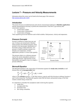
- 1. Measurements Course 4600:483-001 Lecture 7 – Pressure and Velocity Measurements Information about this course can be found at the home page of the instructor: http://gozips.uakron.edu/~dorfi/ Introduction This lecture focuses on standard pressure and velocity measurement techniques in fluid flow applications and the instrumentation necessary to perform the measurements. Fluid flow is governed by thee conservation equations: • Conservation of Mass • Conservation of Momentum • Conservation of Energy These equations govern the fluid flow and its field variables: fluid pressure, velocity and temperature. Pressure Concepts Pressure is defined as contact force per unit area. It always acts inward and is therefore always positive (for absolute pressure). Since Gage pressure is the macroscopic manifestation of Pressure the kinetic energy of fluid molecules, zero Reference pressure is found in absolute vacuum or at Pressure Absolute absolute zero temperature. In fluid Standard System Atmospheric Pressure applications, pressure is a local scalar quantity. Pressure 101.3 KPa abs The pressure relative to a reference pressure 14.696 psia such as the current atmospheric pressure is Perfect called gage pressure. Gage pressure can be Vacuum both positive and negative, since it is simply a Pressure Scales pressure difference. Bernoulli Equation The Bernoulli Equation is the conservation of momentum equation for steady-state, inviscid (no wall friction) flow for an incompressible fluid p1 v12 p v2 + + gh1 = 2 + 2 + gh2 = const ρ 2 ρ 2 where p is the absolute pressure, v is the fluid velocity, g gravity and h the elevation at arbitrary locations 1 and 2 on the stream line. The Bernoulli equation states that the kinetic and potential energy of the fluid remains constant along a stream line. It is important to remember the assumptions made in deriving this equation: • steady flow • incompressible flow • frictionless flow • flow along a streamline Dr. Hans R. Dorfi 11/03/03 Page 1of 4
- 2. Measurements Course 4600:483-001 Manometer The manometer is an instrument, which converts p1 p1 p2 pressure differences into elevation differences (flow velocity is zero). If we define the specific gravity of a Specific x fluid as γ=ρ/g and set the velocity to zero, the Gravity of Bernoulli equation simplifies to Gas: γ p1 + γ h1 = p2 + γ h2 θ L=H /sinθ H Applying the Bernoulli equation to the U-tube Specific Gravity manometer as shown on the right gives the equation of Measurement p1 + γ ( x + H ) = p2 + γ x + γ m H Fluid: γm Solving for the pressure difference yields p1 − p2 = (γ m − γ ) H The pressure difference is directly proportional to the height difference H. The difference in specific weight θ of the measurement fluid and the gas is the proportionality factor. Usually the specific weight of U-tube Manometer (optionally with inclined tube) the measurement fluid is several orders of magnitude larger than the specific weight of the gas. In order to increase the sensitivity of the instrument, one of the arms of the manometers can be inclined by an angle θ. The pressure difference for an inclined manometer is then found from p1 − p2 = p = (γ m − γ ) L sin θ Uncertainty in inclined manometer measurements The above equation shows that the measurement of pressure differentials p with inclined manometers is affected by the uncertainty in the fluid specific weight (density/gravity), the ability to read the manometer (uncertainty in L) and the uncertainty for the inclination angle θ. The normalized uncertainty equation for the manometer is thus given by e p = eγ2m + eγ2 + eL + eθ2 2 Example: An inclined manometer with indicating leg at 30° is used at 20°C to measure a gas pressure of nominal magnitude of 100N/m2 relative to ambient. The specific weight of the measurement fluid is 9770 N/m3. The manometer resolution is 1mm and the specific gravity of the gas is 11.5 N/m3. The relative uncertainty in the specific gravities is assumed to be 1%. We can measure the angle of the inclined tube to within 1° resolution. What is the design state uncertainty for the pressure measurement with this manometer? From the uncertainty analysis we know that the relative uncertainty ei for parameter i is 1 dp ei = Ui p dxi Substitution of the relative uncertainty equation for the specific gravities yields 1 dp γ m Uγ m 9770 eγ m = Uγ m = = * .01 ≈ .01 p dγ m γ m − γ γ m 9770 − 11.5 1 dp Uγ γ Uγ 11.5 eγ = Uγ = = = * .01 ≈ 10 −5 p dγ γm −γ γm −γ γ 9770 − 11.5 Notice how the uncertainty due to the specific gravity of the gas is negligibly small. This is because the specific gravity of the measurement fluid is about 1000 times larger than the gas. Dr. Hans R. Dorfi 11/03/03 Page 2of 4
- 3. Measurements Course 4600:483-001 The relative uncertainty in the length is 1 dp U eL = UL = L p dL L In order to calculate the relative uncertainty, we need to calculate the Length L of the fluid column the manometer at the nominal pressure of 100N/m2. p 100 N / m2 L= = = 0.0205m = 20.5mm (γ m − γ ) sin θ (9770 − 11.5) sin 30o N / m3 The manometer resolution is 1mm, therefore the zero order uncertainty is 0.5mm. The relative uncertainty in length L is therefore UL 0.5mm eL = = = 0.024 L 20.5mm The resolution in the angle measurement is 1°. Therefore the zero order uncertainty is 0.5° or 0.0087 radians. The relative uncertainty in the angle is found from 1 dp Uθ 0.5o 0.0087 rad eθ = Uθ = = = = 0.015 p dθ tan θ tan 30 o 0.5774 Putting all uncertainties together yields e p = 10 −2 * 12 + 10 −3*2 + 2.4 2 + 1.52 = 10 −2 * 1 + 10 −6 + 5.76 + 2.25 = 0.03 = 3% The uncertainty in the length measurement L is the primary contributor to the uncertainty in the pressure measurement. For the nominal pressure of 100N/m2 the design stage uncertainty is 3% or 3N/m2. Pitot-Static Tubes The Bernoulli equation can also be used to measure the fluid velocity. Recall the equation : for zero elevation change p1 is sensed normal to p1v12 p2 v2 2 Point 1: flow direction + = + ρ 2 ρ 2 p1,v1 If we could slow down the fluid flow to zero at point 2, we can solve for the fluid velocity at point 1. = Point 2 2( p2 − p1 ) 2∆p p2,v2=0 v1 = = ρ ρ This is the basic idea of the Pitot-Static tube. The Pitot-Static (P-S) tube consists basically of two concentric tubes, with the end turned through a right angle so that the tip can be faced into the airstream after insertion through the duct wall. The modified ellipsoidal nose form has a single forward facing hole for sensing Total Pressure and a ring of side holes for sensing the Static Pressure. Both these inlets are individually connected to tapping outlets at the tail of the unit. p2 is called the stagnation or total pressure at the forward facing inlet to the Pitot-static probe where the velocity becomes zero, p1 or pstatic is Schematic of Pitot-Static Tube the static pressure along the sides of the Pitot- Dr. Hans R. Dorfi 11/03/03 Page 3of 4
- 4. Measurements Course 4600:483-001 static probe where the velocity is unchanged from the upstream duct velocity v. The pressure difference, ∆P, is called the dynamic pressure because it is related to the change in fluid velocity. We can calculate the duct velocity from the dynamic pressure as 2∆P v= ρ fluid Note that this expression is only accurate if the P-S tube points directly into v1 such that all of v1 is stagnated. If the P-S tube is misaligned, the measured velocity will be too low. Remember that this equation was derived based on the Bernoulli equation, which assumes laminar and incompressible fluid flow. For flow velocities greater than 30% of the sonic velocity, the fluid must be treated as compressible. Then the simplified equation for the P-S tube no longer holds. Textbook descriptions of Pitot-static probes usually describe their use in a laminar flow. What happens when Pitot-static probes are used in time-varying turbulent flows? The pressure difference associated with the fluctuation velocity must move a mass in the pressure sensor to measure the pressure change associated with a given velocity change. The measurement devices are thus second-order mechanical systems with their own natural frequency and damping ratio. If the frequency of the velocity fluctuation is much faster than the natural frequency of the measuring system, then it will display the average value of the fluctuating signal. This will only hold true for moderately turbulent flows (less than 10% turbulence intensity) because the velocity vector must remain approximately parallel to the Pitot-static probe. Duct flows typically have low enough turbulence intensities that the effect of turbulence can be neglected, but disturbed regions of flow near sharp edges or area changes can prevent good readings. Uncertainty in Pitot-Static Tubes See the example in the lecture on uncertainty. Dr. Hans R. Dorfi 11/03/03 Page 4of 4