INTEGRAL FORMS OFTHE
CONSERVATION EQUATIONS
FOR INVISCID FLOW
Chapter 2
2.
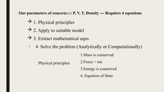
Our parameters ofconcern:::: P, V, T, Density --- Requires 4 equations
1. Physical principles
2. Apply to suitable model
3. Extract mathematical eqns
4. Solve the problem (Analytically or Computationally)
1.Mass is conserved
2.Force = ma
3.Energy is conserved
4. Equation of State
Physical principles:
3.
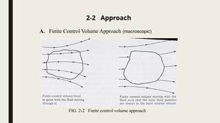
2-2 Approach
A. FiniteControl Volume Approach (macroscopic)
FIG. 2-2 Finite control volume approach
4.
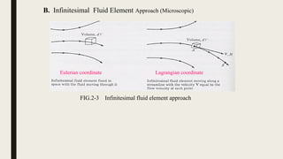
B. Infinitesimal FluidElement Approach (Microscopic)
Eulerian coordinate Lagrangian coordinate
FIG.2-3 Infinitesimal fluid element approach
5.
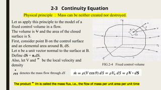
Let us applythis principle to the model of a
fixed control volume in a flow.
The volume is V and the area of the closed
surface is S.
First, consider point B on the control surface
and an elemental area around B, dS.
Let n be a unit vector normal to the surface at B.
Define dS = n.dS.
Also, let V and be the local velocity and
density
2-3 Continuity Equation
Physical principle : Mass can be neither created nor destroyed.
m
denotes the mass flow through dS
FIG.2-4 Fixed control volume
The product Vn is called the mass flux, i.e., the flow of mass per unit area per unit time
6.
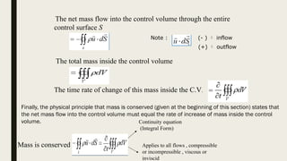
The net massflow into the control volume through the entire
control surface S
The total mass inside the control volume
S
d
u
The time rate of change of this mass inside the C.V.
Mass is conserved
Continuity equation
(Integral Form)
Note : (- ) inflow
(+) outflow
Applies to all flows , compressible
or incompressible , viscous or
inviscid
Finally, the physical principle that mass is conserved (given at the beginning of this section) states that
the net mass flow into the control volume must equal the rate of increase of mass inside the control
volume.
7.
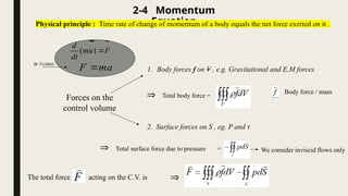
2-4 Momentum
Equation
Physical principle: Time rate of change of momentum of a body equals the net force exerted on it .
Forces on the
control volume
1. Body forces f on V , e.g. Gravitational and E.M forces
2. Surface forces on S , eg. P and τ
Total body force =
Total surface force due to pressure =
The total force acting on the C.V. is
( )
d
mu F
dt
F ma
Body force / mass
We consider inviscid flows only
.
m const
8.
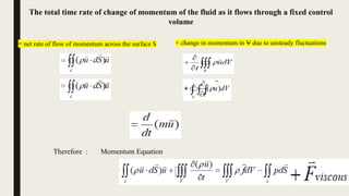
The total timerate of change of momentum of the fluid as it flows through a fixed control
volume
= net rate of flow of momentum across the surface S + change in momentum in V due to unsteady fluctuations
dV
u
t
V
)
(
Therefore : Momentum Equation
9.
Some Observation
■ Thecontinuity equation, Eq. (2.2), and the momentum equation, Eq. (2.1), despite their
complicated-looking integral forms, are powerful tools in the analysis and understanding of
fluid flows.
■ It is important to become familiar with these equations and with the energy equation to be
discussed next, and to understand fully the physical fundamentals they embody.
■ For a study of incompressible flow, the continuity and momentum equations are sufficient
tools to do the job. These equations govern the mechanical aspects of such flows.
■ However, for a compressible flow, the principle of the conservation of energy must be
considered in addition to the continuity and momentum equations.
■ The energy equation is where thermodynamics enters the game of compressible flow, and
this is our next item of business.
10.
2-5 Energy
Equation
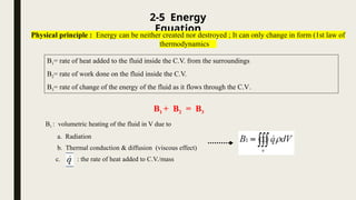
Physical principle: Energy can be neither created nor destroyed ; It can only change in form (1st law of
thermodynamics
B1= rate of heat added to the fluid inside the C.V. from the surroundings
B2= rate of work done on the fluid inside the C.V.
B3= rate of change of the energy of the fluid as it flows through the C.V.
B1 + B2 = B3
B1 : volumetric heating of the fluid in V due to
a. Radiation
b. Thermal conduction & diffusion (viscous effect)
c. : the rate of heat added to C.V./mass
11.
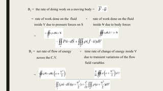
B2 = therate of doing work on a moving body =
= rate of work done on the fluid
inside V due to pressure forces on S
+ rate of work done on the fluid
inside V due to body forces
=
B3 = net rate of flow of energy
across the C.V.
+ time rate of change of energy inside V
due to transient variations of the flow
field variables
=
12.
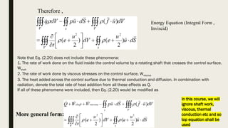
Therefore ,
Energy Equation(Integral Form ,
Inviscid)
More general form:
Note that Eq. (2.20) does not include these phenomena:
1. The rate of work done on the fluid inside the control volume by a rotating shaft that crosses the control surface.
Wshaft
2. The rate of work done by viscous stresses on the control surface, Wviscous
3. The heat added across the control surface due to thermal conduction and diffusion. In combination with
radiation, denote the total rate of heat addition from all these effects as Q.
If all of these phenomena were included, then Eq. (2.20) would be modified as
In this course, we will
ignore shaft work,
viscous, thermal
conduction etc and so
top equation shall be
used
13.
SOME COMMENTS
Remember 4Unknowns P,T, V,
Now 3 Equations: Mass, Momentum
And Energy
4th
Equation: Equation Of State
P=RT
So Now The System Is Solvable
14.
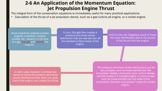
2-6 An Applicationof the Momentum Equation:
Jet Propulsion Engine Thrust
The integral form of the conservation equations is immediately useful for many practical applications.
• Calculation of the thrust of a jet propulsion device, such as a gas turbine jet engine, or a rocket engine.
All jet propulsion engines-turbojet
engines, turbofans, ramjets,
rockets, etc.- depend on the flow
of a gas through and around the
engines.
In turn, this gas flow creates a
pressure and shear stress
distribution that are exerted over all
the exposed surface areas of the
engine,
And it is the net integrated result of these
two local distributions that is the source
of the thrust from the engine.
The pressure and shear stress distributions can be
very complex, such as those exerted over the
compressor blades, combustor cans, turbine blades,
and the nozzle of a turbojet engine, or more simple
such as those exerted over the walls of the
combustion chamber and exhaust nozzle of a rocket
engine.
In each case, however, it is these two
hands of nature-the pressure and shear
stress distributions-that reach out, grab
hold of the engine, and create the thrust.
15.
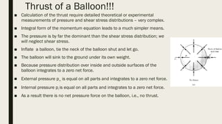
Thrust of aBalloon!!!
■ Calculation of the thrust require detailed theoretical or experimental
measurements of pressure and shear stress distributions – very complex.
■ Integral form of the momentum equation leads to a much simpler means.
■ The pressure is by far the dominant than the shear stress distribution; we
will neglect shear stress.
■ Inflate a balloon, tie the neck of the balloon shut and let go.
■ The balloon will sink to the ground under its own weight.
■ Because pressure distribution over inside and outside surfaces of the
balloon integrates to a zero net force.
■ External pressure p∞ is equal on all parts and integrates to a zero net force.
■ Internal pressure pi is equal on all parts and integrates to a zero net force.
■ As a result there is no net pressure force on the balloon, i.e., no thrust.
16.
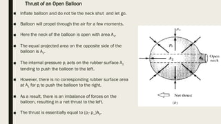
■ Inflate balloonand do not tie the neck shut and let go.
■ Balloon will propel through the air for a few moments.
■ Here the neck of the balloon is open with area A1.
■ The equal projected area on the opposite side of the
balloon is A2.
■ The internal pressure pi acts on the rubber surface A2
tending to push the balloon to the left.
■ However, there is no corresponding rubber surface area
at A1 for pi to push the balloon to the right.
■ As a result, there is an imbalance of forces on the
balloon, resulting in a net thrust to the left.
■ The thrust is essentially equal to (pi- p∞)A2.
Thrust of an Open Balloon
17.
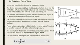
■ Let usnow consider the generic jet propulsion device
■ The device is represented by a duct through which air flows into the
inlet at the left, is pressurized, is burned with fuel inside the duct,
and is exhausted out the exit with an exit jet velocity, Ve
■ The internal pressure acting on the inside surface of the engine is
pi, which varies with location inside the engine.
■ The external pressure acting on the outside surface of the engine is
free-stream ambient pressure p∞, constant over the outside
surface.
■ For an actual engine, duct will be installed in some type of housing,
or nacelle, which will affect the external air pressure.
■ The assumption of constant p∞ on the outer surface yields a thrust
value that is defined as the uninstalled engine thrust.
■ The net force on the engine due to the pressure distribution
Jet Propulsion Engine Thrust
18.
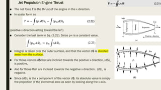
■ The netforce F is the thrust of the engine in the x direction.
■ In scalar form as
(positive x direction acting toward the left)
■ Consider the last term in Eq. (2.22). Since p∞ is a constant value,
■ Integral is taken over the outer surface, and that the vector dS is directed
away from the surface.
■ For those vectors dS that are inclined towards the positive x direction, (dS)x
is positive,
■ And for those that are inclined towards the negative x direction , (dS)x is
negative.
■ Since (dS)x is the x component of the vector dS, its absolute value is simply
the projection of the elemental area as seen by looking along the x axis.
Jet Propulsion Engine Thrust
19.
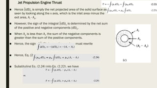
■ Hence ∫(dS)xis simply the net projected area of the solid surface as
seen by looking along the x axis, which is the inlet area minus the
exit area, Ai - Ae.
■ However, the sign of the integral ∫(dS)x is determined by the net sum
of the positive and negative components (dS)x.
■ When Ae is less than Ai, the sum of the negative components is
greater than the sum of the positive components.
■ Hence, the sign of ∫(dS)x is negative, and we must rewrite
■ Hence, Eq. (2.23) becomes
■ Substituting Eq. (2.24) into Eq. (2.22), we have
Jet Propulsion Engine Thrust
20.
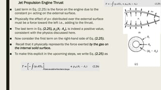
■ Last termin Eq. (2.25) is the force on the engine due to the
constant p∞ acting on the external surface.
■ Physically the effect of p∞ distributed over the external surface
must be a force toward the left i.e., adding to the thrust.
■ The last term in Eq. (2.25), p∞(Ai - Ae), is indeed a positive value,
consistent with the physics discussed here.
■ Now consider the first term on the right-hand side of Eq. (2.25).
■ Recall that it physically represents the force exerted by the gas on
the internal solid surface.
■ To make this explicit in the upcoming steps, we write Eq. (2.25) as
Jet Propulsion Engine Thrust
21.
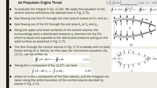
■ To evaluatethe integral in Eq. (2.26), We apply this equation to the
control volume defined by the dashed lines in Fig. 2.7b.
■ Gas flowing into the CV through the inlet area Ai enters at V∞ and p∞.
■ Gas flowing out of the CV through the exit area Ae at Ve and pe.
■ Along the upper and lower surfaces of the control volume, the
surroundings exert a distributed pressure pi directed into the CV;
which is equal and opposite to the distributed pressure acting on the
solid surface as sketched in Fig. 2.7b.
■ The flow through the control volume in Fig. 2.7d is steady with no body
forces acting on it. Hence, for this case the momentum equation, Eq.
(2.11), can be written as
■ Taking the x component of Eq. (2.27), we have
■ where Vx is the x component of the flow velocity, and the integrals are
taken along the entire boundary of the control volume denoted by
abcda in Fig. 2.7d.
Jet Propulsion Engine Thrust
22.
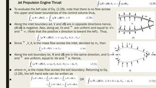
■ To evaluatethe left side of Eq. (2.28), note that there is no flow across
the upper and lower boundaries of the control volume thus,
■ Along the inlet boundary ad, V and dS are in opposite directions hence,
pV.dS is negative. Also, along ad, Vx and are uniform and equal to -V∞
and ∞. (Note that the positive x direction is toward the left). Thus,
■ Since ∞V∞Ai is the mass flow across the inlet, denoted by mi, then
■ Along the exit boundary bc, V and dS are in the same direction, and V,
and are uniform, equal to -Ve and e. Hence,
■ where me is the mass flow across the exit boundary. Returning to Eq.
(2.28), the left hand side can be written as
■ OR
Jet Propulsion Engine Thrust
23.
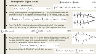
■ Hence, Eq.(2.28) becomes
■ Finally, the integral on the right side of Eq. (2.33) is also taken over the
entire boundary of the control surface in Fig. 2.7d. Hence, in Eq. (2.33),
■ From Fig. 2.7d, note that along ad, dS acts to the left (the positive
direction), and along bc, dS acts to the right (the negative direction),
■ Along the boundaries ab and cd, pi is the distributed pressure acting on
the gas due to the equal and opposite reaction on the solid interior
surface of the engine. Hence, we can write
■ Substituting Eqs. (2.35)-(2.37) into (2.34), we have
Jet Propulsion Engine Thrust
24.
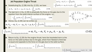
■ Substituting Eq.(2.38) into Eq. (2.33), we have
■ The last term in Eq. (2.39) is physically the force on the gas due to the
reaction from the solid interior surface of the engine, i.e.,
■ Hence, Eq. (2.39) can be written as
■ Or
■ Return to Eq. (2.26) for the engine thrust; here the bracketed term is the
force on the solid surface due to the gas, which from Newton's third law
is equal and opposite to the force on the gas due to the solid surface.
Jet Propulsion Engine Thrust
25.
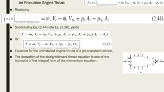
■ Replacing
■ SubstitutingEq. (2.44) into Eq. (2.26), yields
■ Or
■ Equation for the uninstalled engine thrust of a jet propulsion device.
■ The derivation of the straightforward thrust equation is one of the
triumphs of the integral form of the momentum equation.
Jet Propulsion Engine Thrust