BASIC LAWS
Basic Physicallaws of Fluid Mechanics and
Thermodynamics used in Turbomachines
are
:
(
1
)
the continuity of flow equation
(
2
)
the first law of thermodynamics and the
steady flow energy equation
(
3
)
the momentum equation
(
4
)
the second law of thermodynamics
3.
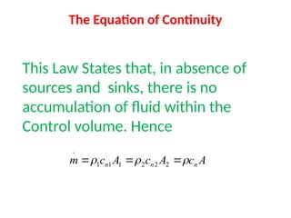
The Equation ofContinuity
This Law States that, in absence of
sources and sinks, there is no
accumulation of fluid within the
Control volume. Hence
A
c
A
c
A
c
m n
n
n
2
2
2
1
1
1
.
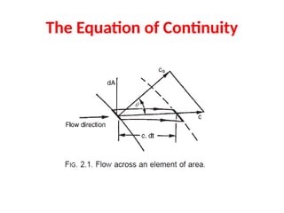
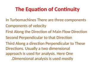
The Equation ofContinuity
In Turbomachines There are three components
Components of velocity
First Along the Direction of Main Flow Direction
Second Perpendicular to that Direction
Third Along a direction Perpendicular to These
Directions. Usually a two dimensional
approach is used for analysis. Here One
Dimensional analysis is used mostly
.
6.
The First Lawof Thermodynamics [Internal
Energy]
The first law of thermodynamics states that if a
system is taken through a complete cycle during
which heat is supplied and work is done, then
where represents the heat supplied to the
system during the cycle and the work done
by the system during the cycle. The units of
heat and work are taken to be the same.
0
W
Q
7.
The First Lawof Thermodynamics [Internal
Energy]
During a change of state from 1 to 2, there is a
change in the property internal energy and
the law is written as
For an infinitesimal change of state
dE= δQ – δW
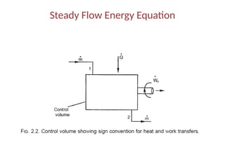
The Steady FlowEnergy Equation
First law of thermodynamics is applied to the
steady flow of fluid through a control volume
so that the steady flow energy equation is
obtained. Energy is transferred from the fluid
to the blades of the turbomachine, positive
work being done (via the shaft) at the rate W.
In the general case positive heat transfer takes
place from the surroundings to the control
volume
.
10.
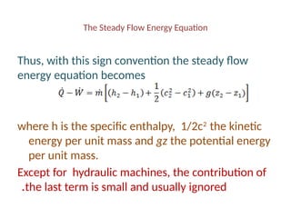
The Steady FlowEnergy Equation
Thus, with this sign convention the steady flow
energy equation becomes
where h is the specific enthalpy, 1/2c2
the kinetic
energy per unit mass and gz the potential energy
per unit mass.
Except for hydraulic machines, the contribution of
the last term is small and usually ignored
.
11.
The Steady FlowEnergy Equation
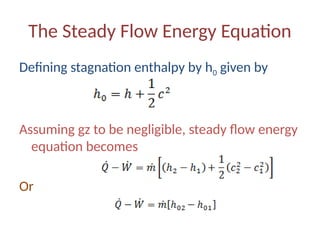
Defining stagnation enthalpy by h0 given by
Assuming gz to be negligible, steady flow energy
equation becomes
Or
12.
The Steady FlowEnergy Equation
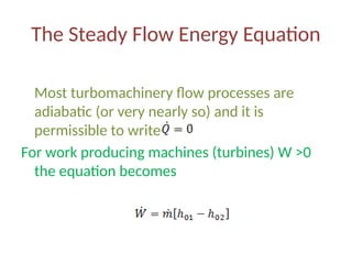
Most turbomachinery flow processes are
adiabatic (or very nearly so) and it is
permissible to write
For work producing machines (turbines) W ˃0
the equation becomes
13.
The Steady FlowEnergy Equation
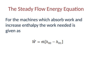
For the machines which absorb work and
increase enthalpy the work needed is
given as
14.
Momentum Equation
Newton’s SecondLaw of Motion
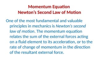
One of the most fundamental and valuable
principles in mechanics is Newton’s second
law of motion. The momentum equation
relates the sum of the external forces acting
on a fluid element to its acceleration, or to the
rate of change of momentum in the direction
of the resultant external force.
15.
Momentum Equation
Newton’s SecondLaw of Motion
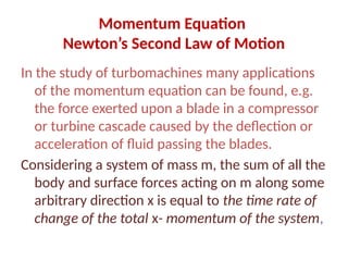
In the study of turbomachines many applications
of the momentum equation can be found, e.g.
the force exerted upon a blade in a compressor
or turbine cascade caused by the deflection or
acceleration of fluid passing the blades.
Considering a system of mass m, the sum of all the
body and surface forces acting on m along some
arbitrary direction x is equal to the time rate of
change of the total x- momentum of the system,
16.
Momentum Equation
Newton’s SecondLaw of Motio
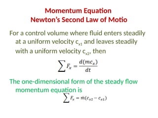
For a control volume where fluid enters steadily
at a uniform velocity cx1 and leaves steadily
with a uniform velocity cx2, then
The one-dimensional form of the steady flow
momentum equation is
17.
Euler’s Equation ofMotion
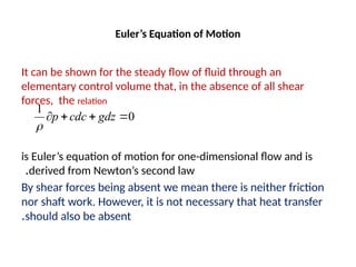
It can be shown for the steady flow of fluid through an
elementary control volume that, in the absence of all shear
forces, the relation
is Euler’s equation of motion for one-dimensional flow and is
derived from Newton’s second law
.
By shear forces being absent we mean there is neither friction
nor shaft work. However, it is not necessary that heat transfer
should also be absent
.
0
1
gdz
cdc
p
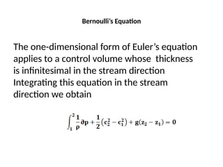
Bernoulli’s Equation
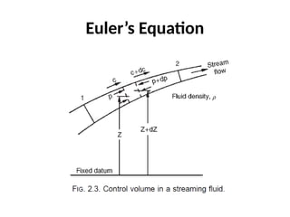
The one-dimensionalform of Euler’s equation
applies to a control volume whose thickness
is infinitesimal in the stream direction
Integrating this equation in the stream
direction we obtain
20.
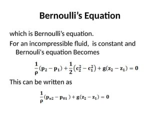
Bernoulli’s Equation
which isBernoulli’s equation.
For an incompressible fluid, is constant and
Bernouli's equation Becomes
This can be written as
21.
Bernoulli’s Equation
Where stagnationpressure p02 and p01 are the
stagnation pressures at 2 and 1 station
respectively. Stagnation pressures are given as
22.
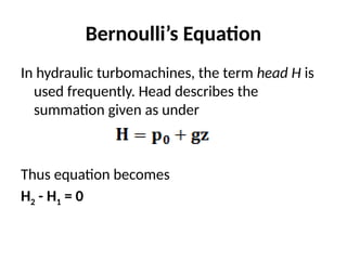
Bernoulli’s Equation
In hydraulicturbomachines, the term head H is
used frequently. Head describes the
summation given as under
Thus equation becomes
H2 - H1 = 0
23.
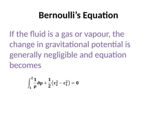
Bernoulli’s Equation
If thefluid is a gas or vapour, the
change in gravitational potential is
generally negligible and equation
becomes
24.
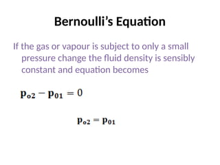
Bernoulli’s Equation
If thegas or vapour is subject to only a small
pressure change the fluid density is sensibly
constant and equation becomes
25.
Bernoulli’s Equation
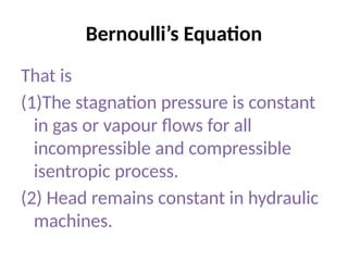
That is
(1)Thestagnation pressure is constant
in gas or vapour flows for all
incompressible and compressible
isentropic process.
(2) Head remains constant in hydraulic
machines.
26.
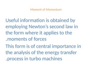
Moment of Momentum
Usefulinformation is obtained by
employing Newton’s second law in
the form where it applies to the
moments of forces
.
This form is of central importance in
the analysis of the energy transfer
process in turbo machines
.
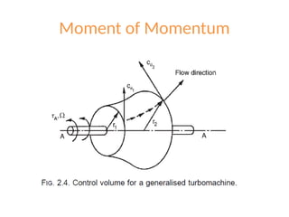
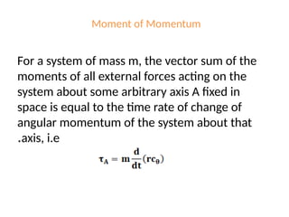
Moment of Momentum
Fora system of mass m, the vector sum of the
moments of all external forces acting on the
system about some arbitrary axis A fixed in
space is equal to the time rate of change of
angular momentum of the system about that
axis, i.e
.
29.
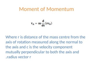
Moment of Momentum
Wherer is distance of the mass centre from the
axis of rotation measured along the normal to
the axis and c is the velocity component
mutually perpendicular to both the axis and
radius vector r
.
30.
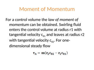
Moment of Momentum
Fora control volume the law of moment of
momentum can be obtained. Swirling fluid
enters the control volume at radius r1 with
tangential velocity cθ1 and leaves at radius r2
with tangential velocity cθ2. For one-
dimensional steady flow
31.
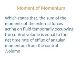
Moment of Momentum
Whichstates that, the sum of the
moments of the external forces
acting on fluid temporarily occupying
the control volume is equal to the
net time rate of efflux of angular
momentum from the control
volume
.
32.
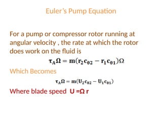
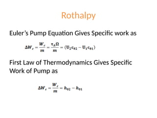
Euler’s Pump Equation
Fora pump or compressor rotor running at
angular velocity , the rate at which the rotor
does work on the fluid is
Which Becomes
Where blade speed U =Ω r
33.
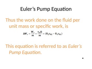
Euler’s Pump Equation
Thusthe work done on the fluid per
unit mass or specific work, is
This equation is referred to as Euler’s
Pump Equation.
•
34.
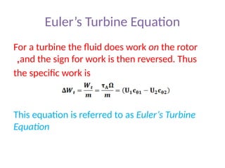
Euler’s Turbine Equation
Fora turbine the fluid does work on the rotor
and the sign for work is then reversed. Thus
,
the specific work is
This equation is referred to as Euler’s Turbine
Equation
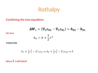
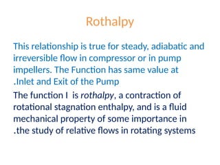
Rothalpy
This relationship istrue for steady, adiabatic and
irreversible flow in compressor or in pump
impellers. The Function has same value at
Inlet and Exit of the Pump
.
The function I is rothalpy, a contraction of
rotational stagnation enthalpy, and is a fluid
mechanical property of some importance in
the study of relative flows in rotating systems
.
38.
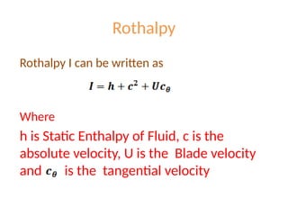
Rothalpy
Rothalpy I canbe written as
Where
h is Static Enthalpy of Fluid, c is the
absolute velocity, U is the Blade velocity
and is the tangential velocity
39.
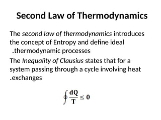
Second Law ofThermodynamics
The second law of thermodynamics introduces
the concept of Entropy and define ideal
thermodynamic processes
.
The Inequality of Clausius states that for a
system passing through a cycle involving heat
exchanges
.
40.
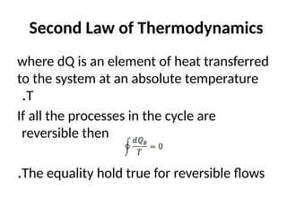
Second Law ofThermodynamics
where dQ is an element of heat transferred
to the system at an absolute temperature
T
.
If all the processes in the cycle are
reversible then
The equality hold true for reversible flows
.
41.
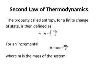
Second Law ofThermodynamics
The property called entropy, for a finite change
of state, is then defined as
For an incremental
where m is the mass of the system.
42.
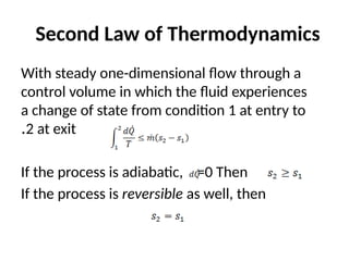
Second Law ofThermodynamics
With steady one-dimensional flow through a
control volume in which the fluid experiences
a change of state from condition 1 at entry to
2 at exit
.
If the process is adiabatic, =0 Then
If the process is reversible as well, then
43.
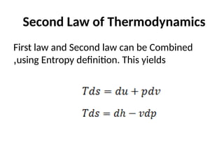
Second Law ofThermodynamics
First law and Second law can be Combined
using Entropy definition. This yields
,
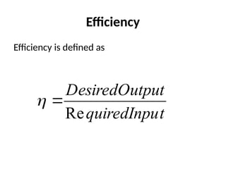
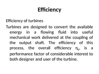
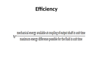
Efficiency
Efficiency of turbines
Turbinesare designed to convert the available
energy in a flowing fluid into useful
mechanical work delivered at the coupling of
the output shaft. The efficiency of this
process, the overall efficiency η0, is a
performance factor of considerable interest to
both designer and user of the turbine.
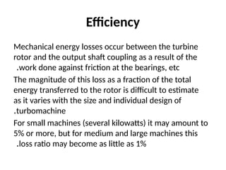
Efficiency
Mechanical energy lossesoccur between the turbine
rotor and the output shaft coupling as a result of the
work done against friction at the bearings, etc
.
The magnitude of this loss as a fraction of the total
energy transferred to the rotor is difficult to estimate
as it varies with the size and individual design of
turbomachine
.
For small machines (several kilowatts) it may amount to
5% or more, but for medium and large machines this
loss ratio may become as little as 1%
.
48.
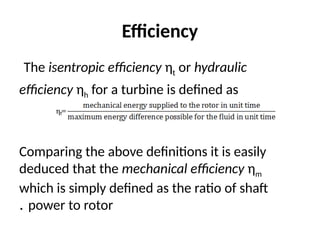
Efficiency
The isentropic efficiencyηt or hydraulic
efficiency ηh for a turbine is defined as
Comparing the above definitions it is easily
deduced that the mechanical efficiency ηm
which is simply defined as the ratio of shaft
power to rotor
.
49.
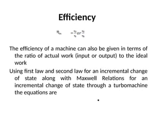
Efficiency
ηm
The efficiency ofa machine can also be given in terms of
the ratio of actual work (input or output) to the ideal
work
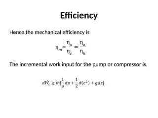
Using first law and second law for an incremental change
of state along with Maxwell Relations for an
incremental change of state through a turbomachine
the equations are
•
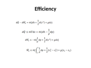
Efficiency
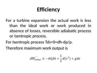
For a turbineexpansion the actual work is less
than the ideal work or work produced in
absence of losses, reversible adiabatic process
or isentropic process.
For Isentropic process Tds=0=dh-dp/ρ.
Therefore maximum work output is
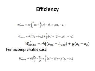
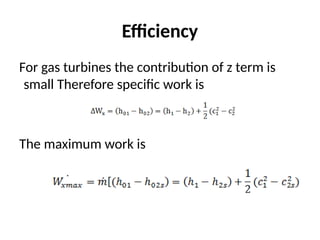
Efficiency
For gas turbinesthe contribution of z term is
small Therefore specific work is
The maximum work is
54.
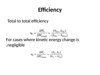
Efficiency
where the subscriptsdenotes that the change of state
between 1 and
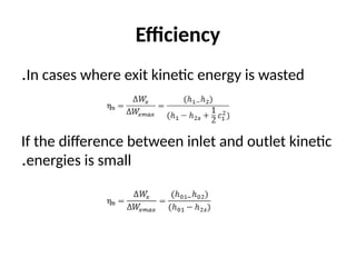
There are several ways of expressing efficiency, the
choice of definition depending largely upon whether
the exit kinetic energy is usefully employed or is
wasted. An example where the exhaust kinetic
energy is not wasted is from the last stage of an
aircraft gas turbine where it contributes to the jet
propulsive thrust. The total to total efficiency is
given as
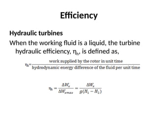
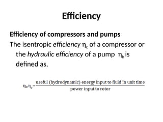
Efficiency
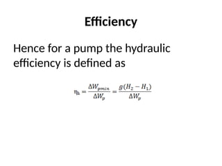
Efficiency of compressorsand pumps
The isentropic efficiency ηc of a compressor or
the hydraulic efficiency of a pump ηh is
defined as,
59.
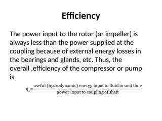
Efficiency
The power inputto the rotor (or impeller) is
always less than the power supplied at the
coupling because of external energy losses in
the bearings and glands, etc. Thus, the
overall ,efficiency of the compressor or pump
is
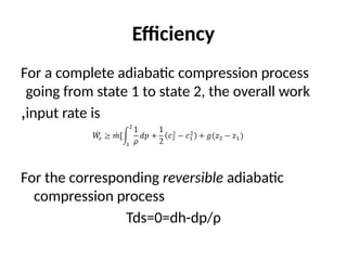
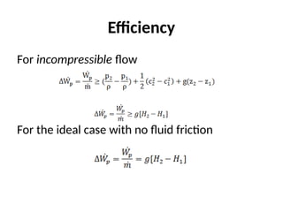
Efficiency
For a completeadiabatic compression process
going from state 1 to state 2, the overall work
input rate is
,
For the corresponding reversible adiabatic
compression process
Tds=0=dh-dp/ρ
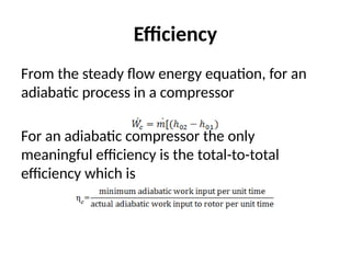
Efficiency
From the steadyflow energy equation, for an
adiabatic process in a compressor
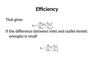
For an adiabatic compressor the only
meaningful efficiency is the total-to-total
efficiency which is
Small Stage orPolytropic Efficiency
The isentropic efficiency although fundamentally valid,
can be misleading if used for comparing the efficiencies
of turbomachines of differing pressure ratios.
Any turbomachine may be regarded as being composed
of a large number of very small stages irrespective of
the actual number of stages in the machine. If each
small stage has the same efficiency, then the isentropic
efficiency of the whole machine will be different from
the small stage efficiency, the difference depending
upon the pressure ratio of the machine.
68.
Small Stage orPolytropic Efficiency
Compression process
It is assumed that the compression process may
be divided up into a large number of small
stages of equal efficiency p. For each small
stage the actual work input is and the
corresponding ideal work in the isentropic
process is .
69.
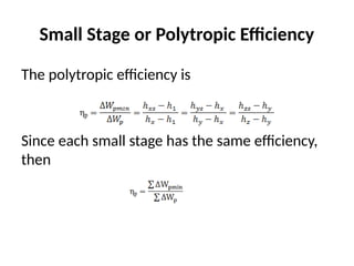
Small Stage orPolytropic Efficiency
The polytropic efficiency is
Since each small stage has the same efficiency,
then
70.
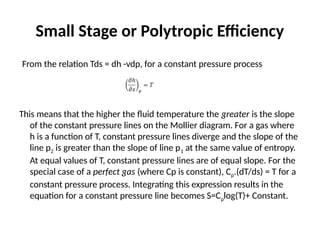
Small Stage orPolytropic Efficiency
From the relation Tds = dh -vdp, for a constant pressure process
This means that the higher the fluid temperature the greater is the slope
of the constant pressure lines on the Mollier diagram. For a gas where
h is a function of T, constant pressure lines diverge and the slope of the
line p2 is greater than the slope of line p1 at the same value of entropy.
At equal values of T, constant pressure lines are of equal slope. For the
special case of a perfect gas (where Cp is constant), Cp.(dT/ds) = T for a
constant pressure process. Integrating this expression results in the
equation for a constant pressure line becomes S=Cplog(T)+ Constant.
71.
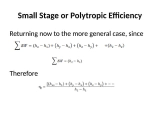
Small Stage orPolytropic Efficiency
Returning now to the more general case, since
Therefore
72.
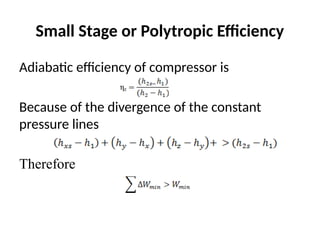
Small Stage orPolytropic Efficiency
Adiabatic efficiency of compressor is
Because of the divergence of the constant
pressure lines
Therefore
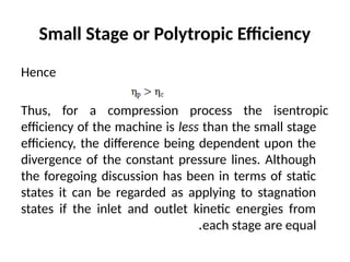
73.
Small Stage orPolytropic Efficiency
Hence
Thus, for a compression process the isentropic
efficiency of the machine is less than the small stage
efficiency, the difference being dependent upon the
divergence of the constant pressure lines. Although
the foregoing discussion has been in terms of static
states it can be regarded as applying to stagnation
states if the inlet and outlet kinetic energies from
each stage are equal
.
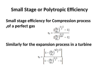
74.
Small Stage orPolytropic Efficiency
Small stage efficiency for Compression process
of a perfect gas
,
Similarly for the expansion process in a turbine
75.
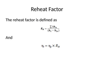
Reheat Factor
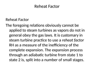
Reheat Factor
Theforegoing relations obviously cannot be
applied to steam turbines as vapors do not in
general obey the gas laws. It is customary in
steam turbine practice to use a reheat factor
RH as a measure of the inefficiency of the
complete expansion. The expansion process
through an adiabatic turbine from state 1 to
state 2 is, split into a number of small stages.
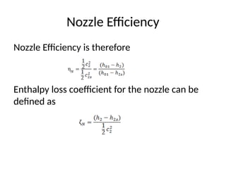
Nozzle Efficiency
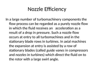
In alarge number of turbomachinery components the
flow process can be regarded as a purely nozzle flow
in which the fluid receives an acceleration as a
result of a drop in pressure. Such a nozzle flow
occurs at entry to all turbomachines and in the
stationary blade rows in turbines. In axial machines
the expansion at entry is assisted by a row of
stationary blades (called guide vanes in compressors
and nozzles in turbines) which direct the fluid on to
the rotor with a large swirl angle.
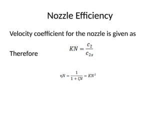
78.
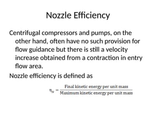
Nozzle Efficiency
Centrifugal compressorsand pumps, on the
other hand, often have no such provision for
flow guidance but there is still a velocity
increase obtained from a contraction in entry
flow area.
Nozzle efficiency is defined as
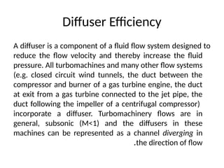
Diffuser Efficiency
A diffuseris a component of a fluid flow system designed to
reduce the flow velocity and thereby increase the fluid
pressure. All turbomachines and many other flow systems
(e.g. closed circuit wind tunnels, the duct between the
compressor and burner of a gas turbine engine, the duct
at exit from a gas turbine connected to the jet pipe, the
duct following the impeller of a centrifugal compressor)
incorporate a diffuser. Turbomachinery flows are in
general, subsonic (M<1) and the diffusers in these
machines can be represented as a channel diverging in
the direction of flow
.
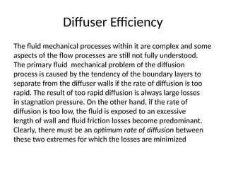
82.
Diffuser Efficiency
The fluidmechanical processes within it are complex and some
aspects of the flow processes are still not fully understood.
The primary fluid mechanical problem of the diffusion
process is caused by the tendency of the boundary layers to
separate from the diffuser walls if the rate of diffusion is too
rapid. The result of too rapid diffusion is always large losses
in stagnation pressure. On the other hand, if the rate of
diffusion is too low, the fluid is exposed to an excessive
length of wall and fluid friction losses become predominant.
Clearly, there must be an optimum rate of diffusion between
these two extremes for which the losses are minimized
83.
Diffuser Efficiency
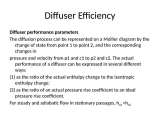
Diffuser performanceparameters
The diffusion process can be represented on a Mollier diagram by the
change of state from point 1 to point 2, and the corresponding
changes in
pressure and velocity from p1 and c1 to p2 and c2. The actual
performance of a diffuser can be expressed in several different
ways:
(1) as the ratio of the actual enthalpy change to the isentropic
enthalpy change;
(2) as the ratio of an actual pressure rise coefficient to an ideal
pressure rise coefficient.
For steady and adiabatic flow in stationary passages, h01 =h02
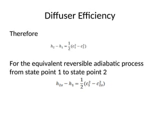
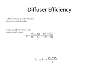
Diffuser Efficiency
A diffuserefficiency, also called the diffuser
effectiveness, can be defined as
,
In a low speed flow the density can be
considered nearly constantt
.
.
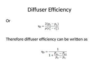
Diffuser Efficiency
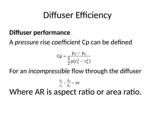
Diffuser performance
Apressure rise coefficient Cp can be defined
For an incompressible flow through the diffuser
Where AR is aspect ratio or area ratio.
88.
Diffuser Efficiency
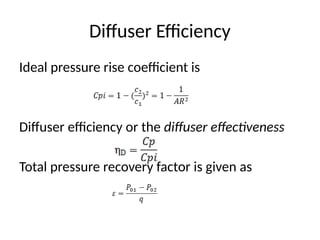
Ideal pressurerise coefficient is
Diffuser efficiency or the diffuser effectiveness
Total pressure recovery factor is given as

![The First Law of Thermodynamics [Internal
Energy]
The first law of thermodynamics states that if a
system is taken through a complete cycle during
which heat is supplied and work is done, then
where represents the heat supplied to the
system during the cycle and the work done
by the system during the cycle. The units of
heat and work are taken to be the same.
0
W
Q
](https://image.slidesharecdn.com/chapter2turbo588-250819084209-e77efbd2/85/ThermoFluid-Course-for-Mechanical-Engineers-pptx-6-320.jpg)
![The First Law of Thermodynamics [Internal
Energy]
During a change of state from 1 to 2, there is a
change in the property internal energy and
the law is written as
For an infinitesimal change of state
dE= δQ – δW](https://image.slidesharecdn.com/chapter2turbo588-250819084209-e77efbd2/85/ThermoFluid-Course-for-Mechanical-Engineers-pptx-7-320.jpg)


![FIRST LAW OF THERMODYNAMICS [Advanced Thermodynamics]](https://cdn.slidesharecdn.com/ss_thumbnails/firstlawofthermodynamics-250308050053-40285757-thumbnail.jpg?width=640&height=640&fit=bounds)


