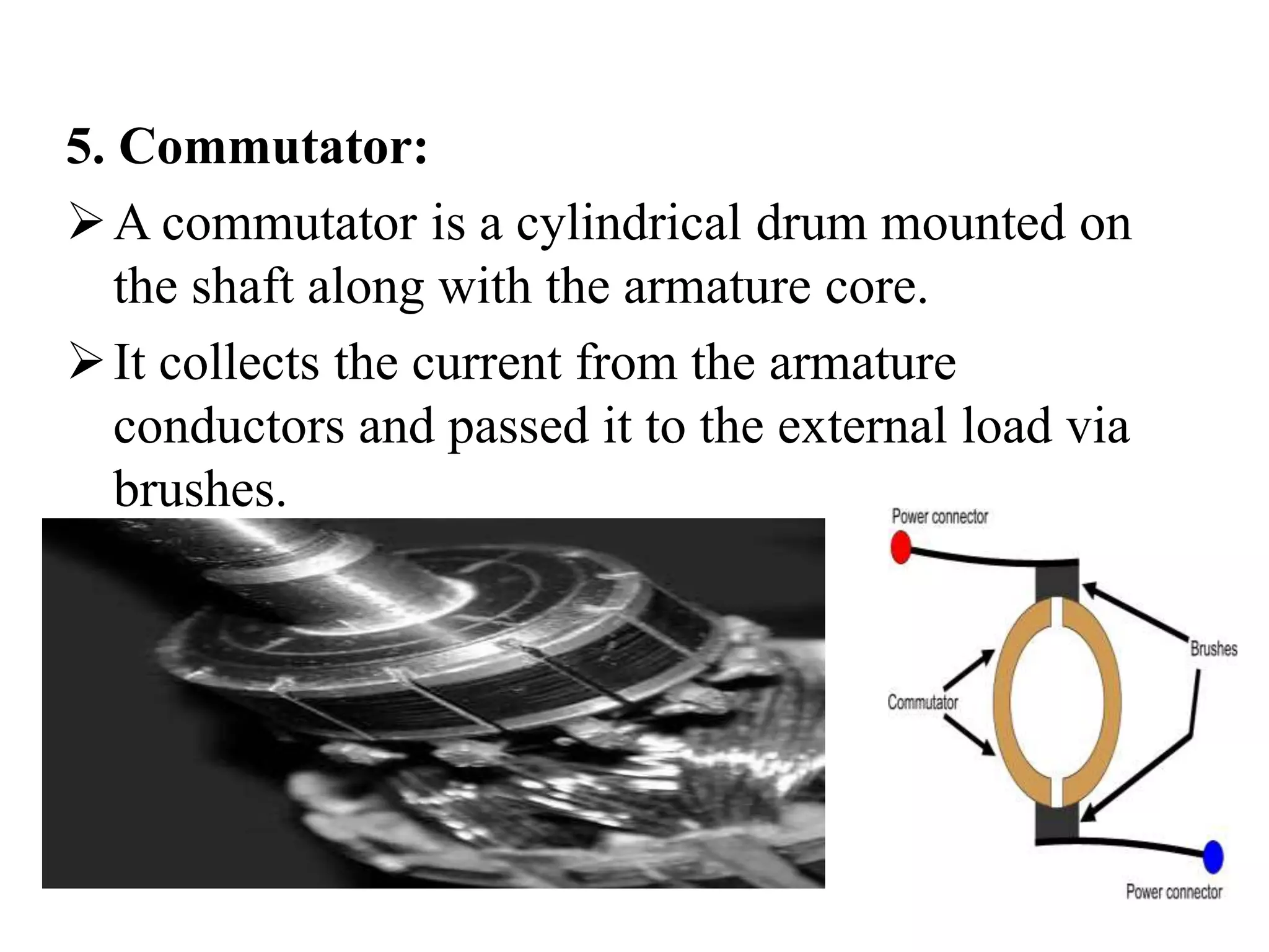
DC MACHINES
OBJECTIVES
1)BASIC FUNDAMENTAL OF MACHINE
2)APPLICATION OF MACHINE
Construction Of A DC Machine:
4-pole DC machine.
• Important parts of DC motor:
1. Yoke 4. Armature
2. Field winding 5. Commutator, brushes &
gear
3. poles 6. Brushes
1. Yoke:
 It acts as the outer support of a DC motor.
 It provides mechanical support for the poles.
2. Poles:
pole of a dc motor is an electromagnet.
The field winding is wound over the poles.
Poles produces magnetic flux when the filed
winding is excited.
3. Field winding:
 The coils wound around the pole are called
field coils and they are connected in series with
each other to form field winding.
 When current passing through the field
winding, magnetic flux produced in the air gap
between pole and armature.
Field winding
4. Armature:
Armature is a cylindrical drum mounted on shaft
in which number of slots are provided.
Armature conductors are placed in these slots.
Theses armature conductors are interconnected to
form the armature winding.
Armature winding
There are 2 types of winding
Lap and Wave winding
Lap winding
A = P
The armature
windings are
divided into
no. of sections
equal to the no
of poles
Wave winding
A = 2
It is used in low
current output
and high voltage.
2 brushes
5. Commutator:
A commutator is a cylindrical drum mounted on
the shaft along with the armature core.
It collects the current from the armature
conductors and passed it to the external load via
brushes.
6. Brushes:
 Commutator is rotating. So it is not possible to connect
the load directly to it.
 Hence current is conducted from the armature to the
external load by the carbon brushes which are held
against the surface of commutator by springs.
Carbon brushes are used in DC machines because they are
soft materials
It does not generate spikes when they contact commutator
Carbon is used for brushes because it has negative
temperature coefficient of resistance
Windings in DC Machine
• In any dc machines, there are two windings:
1. Field winding 2. Armature winding
• Out of these, the field winding is stationary
which does not move at all and armature
winding is mounted on a shaft. So it can rotate
freely.
• Connection of windings for operation as motor:
 To operate the dc machine as a motor, the field
winding and armature winding is connected
across a dc power supply.
Working principle
A motor works on the principles of Faraday’s law of
electromagnetic induction.
Whenever a conductor is moved in the magnetic field
, an emf is induced and the magnitude of the induced
emf is directly proportional to the rate of change of flux
linkage.
This emf causes a current flow if the conductor
circuit is closed .
Fleming’s Right hand rule
EMF equation
Let,
Ø= flux per pole in weber
Z = Total number of conductor
P = Number of poles
A = Number of parallel paths
N =armature speed in rpm
Eg = emf generated in any on of the
parallel path
EMF equation
Flux cut by 1 conductor
in 1 revolution = P * φ
Flux cut by 1 conductor in
60 sec = P φ N /60
Avg emf generated in 1
conductor = PφN/60
Number of conductors in
each parallel path = Z /A
Eg = PφNZ/60A
Torque
The turning or twisting force about an
axis is called torque .
P = T * 2 πN/ 60
Eb Ia = Ta * 2 πN/ 60
T ∞ φ I a
Ta ∞ I2a
DC Shunt Motor
• In DC shunt type motor, field and armature
winding are connected in parallel as shown in
fig. and this combination is connected across a
common dc power supply.
DC Series Motor
• In DC series motor, the armature and field
windings are connected in series with each
other.
∴ ø ∝ Ia
∴ ø ∝ Is
DC Compound Motor
Fig.(1): Long shunt compound dc motor fig.(2):Short shunt compound dc motor
Starters for DC motors
Needed to limit the starting current .
1. Two point starter
2. Three point starter
3. Four point starter
Applications:
Shunt Motor:
Blowers and fans
Centrifugal and reciprocating pumps
Lathe machines
Machine tools
Milling machines
Drilling machines
Series Motor:
Cranes
Hoists , Elevators
Trolleys
Conveyors
Electric locomotives
Applications:
Cumulative compound Motor:
Rolling mills
Punches
Shears
Heavy planers
Elevators
Applications:
Applications:
Shunt Motor:
Blowers and fans
Centrifugal and reciprocating pumps
Lathe machines
Machine tools
Milling machines
Drilling machines
Series Motor:
Cranes
Hoists , Elevators
Trolleys
Conveyors
Electric locomotives
Applications:
Cumulative compound Motor:
Rolling mills
Punches
Shears
Heavy planers
Elevators
Applications:
APPLICATION
Used for the loads which require a
gradual buildup of torque. Used for
the loads that require speed control.
The wound rotor induction
motors are used in conveyors, cranes,
pumps, elevators and compressors.
Synchronous Motor
It is used where high power at low speed
is required. Such as rolling mills, chippers,
mixers, pumps, pumps, compressor etc.

PPT of DC machine.pptx

  • 2.
  • 3.
    OBJECTIVES 1)BASIC FUNDAMENTAL OFMACHINE 2)APPLICATION OF MACHINE
  • 5.
    Construction Of ADC Machine: 4-pole DC machine.
  • 6.
    • Important partsof DC motor: 1. Yoke 4. Armature 2. Field winding 5. Commutator, brushes & gear 3. poles 6. Brushes 1. Yoke:  It acts as the outer support of a DC motor.  It provides mechanical support for the poles.
  • 7.
    2. Poles: pole ofa dc motor is an electromagnet. The field winding is wound over the poles. Poles produces magnetic flux when the filed winding is excited. 3. Field winding:  The coils wound around the pole are called field coils and they are connected in series with each other to form field winding.  When current passing through the field winding, magnetic flux produced in the air gap between pole and armature.
  • 8.
  • 9.
    4. Armature: Armature isa cylindrical drum mounted on shaft in which number of slots are provided. Armature conductors are placed in these slots. Theses armature conductors are interconnected to form the armature winding.
  • 10.
    Armature winding There are2 types of winding Lap and Wave winding Lap winding A = P The armature windings are divided into no. of sections equal to the no of poles Wave winding A = 2 It is used in low current output and high voltage. 2 brushes
  • 11.
    5. Commutator: A commutatoris a cylindrical drum mounted on the shaft along with the armature core. It collects the current from the armature conductors and passed it to the external load via brushes.
  • 12.
    6. Brushes:  Commutatoris rotating. So it is not possible to connect the load directly to it.  Hence current is conducted from the armature to the external load by the carbon brushes which are held against the surface of commutator by springs. Carbon brushes are used in DC machines because they are soft materials It does not generate spikes when they contact commutator Carbon is used for brushes because it has negative temperature coefficient of resistance
  • 14.
    Windings in DCMachine • In any dc machines, there are two windings: 1. Field winding 2. Armature winding • Out of these, the field winding is stationary which does not move at all and armature winding is mounted on a shaft. So it can rotate freely. • Connection of windings for operation as motor:  To operate the dc machine as a motor, the field winding and armature winding is connected across a dc power supply.
  • 15.
    Working principle A motorworks on the principles of Faraday’s law of electromagnetic induction. Whenever a conductor is moved in the magnetic field , an emf is induced and the magnitude of the induced emf is directly proportional to the rate of change of flux linkage. This emf causes a current flow if the conductor circuit is closed .
  • 17.
  • 19.
    EMF equation Let, Ø= fluxper pole in weber Z = Total number of conductor P = Number of poles A = Number of parallel paths N =armature speed in rpm Eg = emf generated in any on of the parallel path
  • 20.
    EMF equation Flux cutby 1 conductor in 1 revolution = P * φ Flux cut by 1 conductor in 60 sec = P φ N /60 Avg emf generated in 1 conductor = PφN/60 Number of conductors in each parallel path = Z /A Eg = PφNZ/60A
  • 21.
    Torque The turning ortwisting force about an axis is called torque . P = T * 2 πN/ 60 Eb Ia = Ta * 2 πN/ 60 T ∞ φ I a Ta ∞ I2a
  • 22.
    DC Shunt Motor •In DC shunt type motor, field and armature winding are connected in parallel as shown in fig. and this combination is connected across a common dc power supply.
  • 23.
    DC Series Motor •In DC series motor, the armature and field windings are connected in series with each other. ∴ ø ∝ Ia ∴ ø ∝ Is
  • 24.
    DC Compound Motor Fig.(1):Long shunt compound dc motor fig.(2):Short shunt compound dc motor
  • 26.
    Starters for DCmotors Needed to limit the starting current . 1. Two point starter 2. Three point starter 3. Four point starter
  • 27.
    Applications: Shunt Motor: Blowers andfans Centrifugal and reciprocating pumps Lathe machines Machine tools Milling machines Drilling machines
  • 28.
    Series Motor: Cranes Hoists ,Elevators Trolleys Conveyors Electric locomotives Applications:
  • 29.
    Cumulative compound Motor: Rollingmills Punches Shears Heavy planers Elevators Applications:
  • 30.
    Applications: Shunt Motor: Blowers andfans Centrifugal and reciprocating pumps Lathe machines Machine tools Milling machines Drilling machines
  • 31.
    Series Motor: Cranes Hoists ,Elevators Trolleys Conveyors Electric locomotives Applications:
  • 32.
    Cumulative compound Motor: Rollingmills Punches Shears Heavy planers Elevators Applications:
  • 43.
    APPLICATION Used for theloads which require a gradual buildup of torque. Used for the loads that require speed control. The wound rotor induction motors are used in conveyors, cranes, pumps, elevators and compressors.
  • 44.
  • 45.
    It is usedwhere high power at low speed is required. Such as rolling mills, chippers, mixers, pumps, pumps, compressor etc.