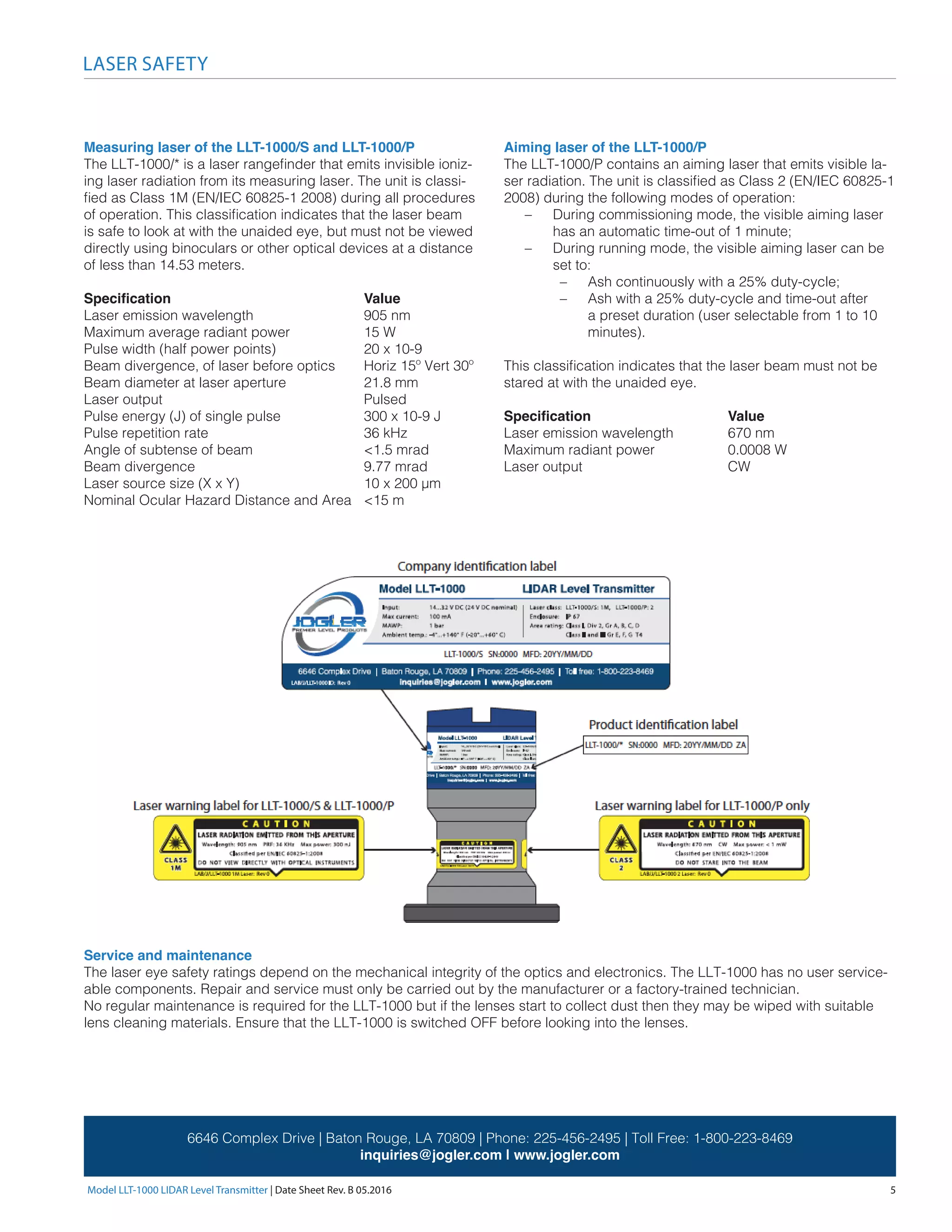
Download to read offline
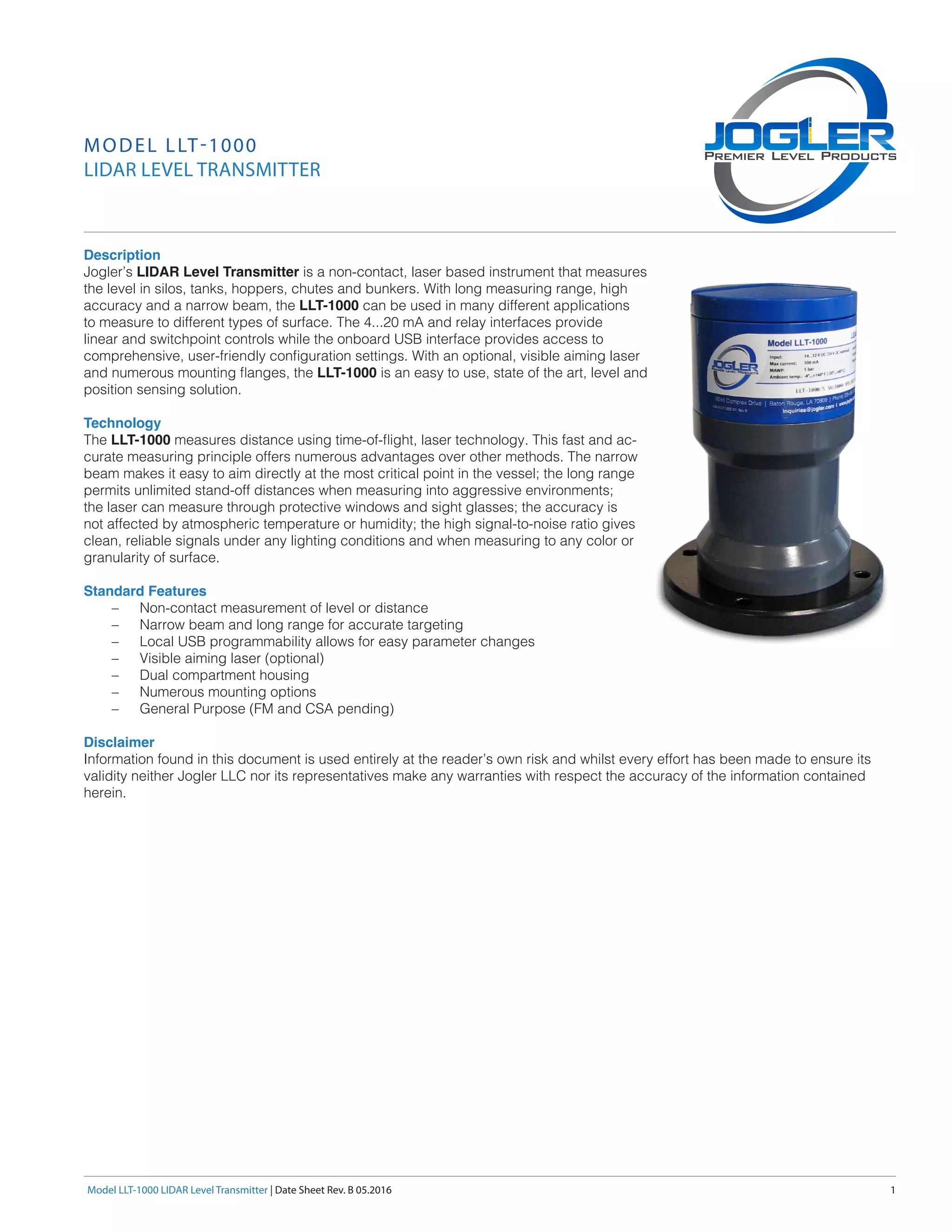
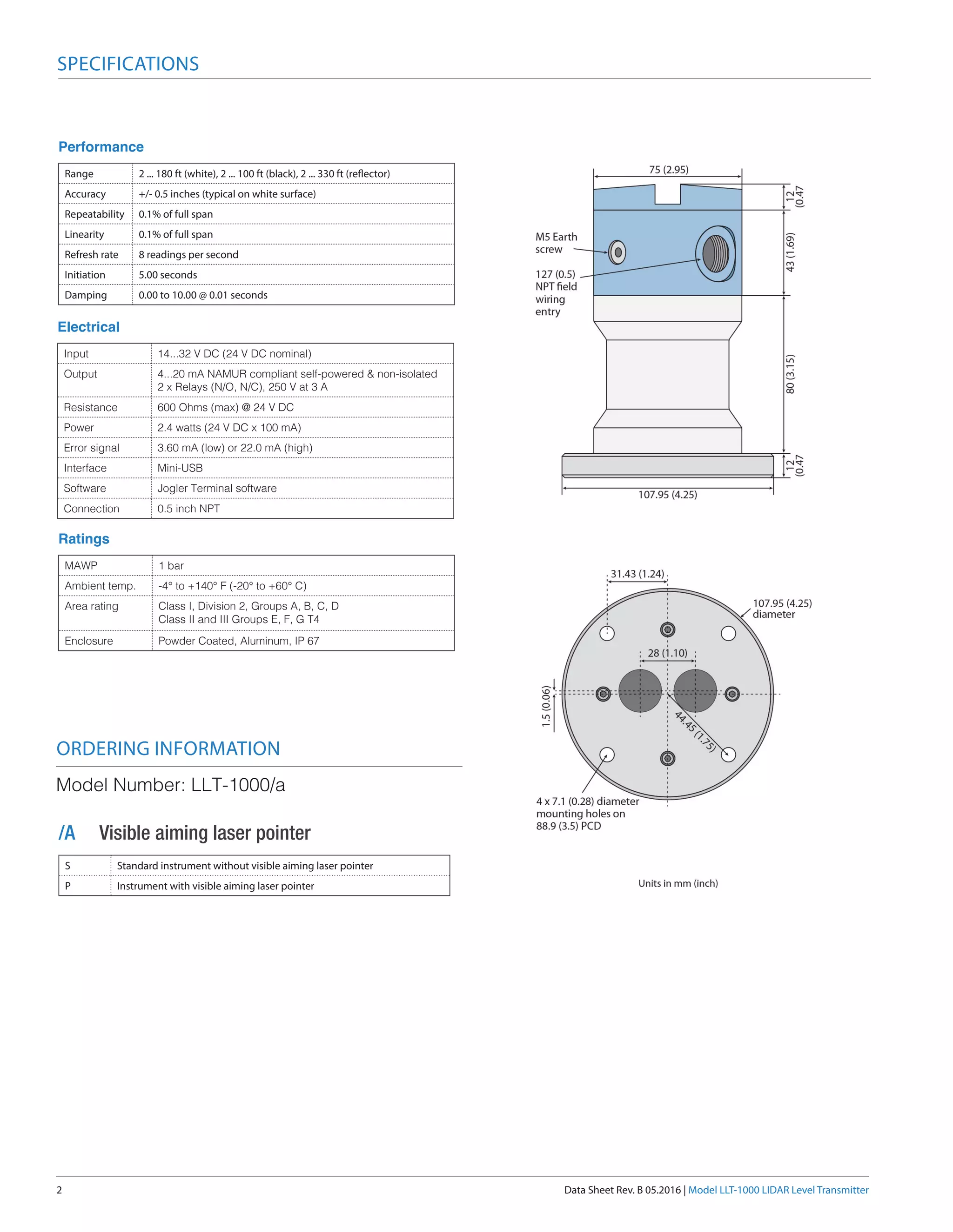
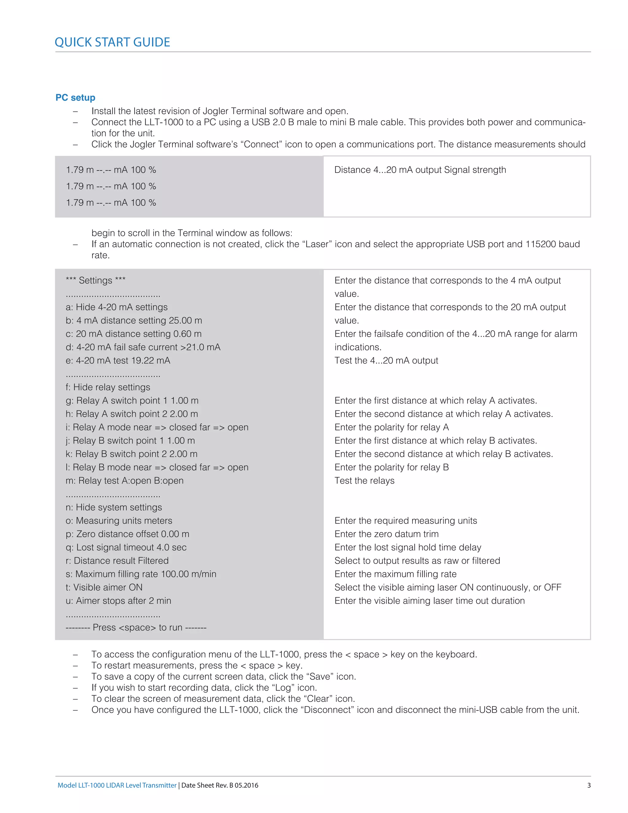
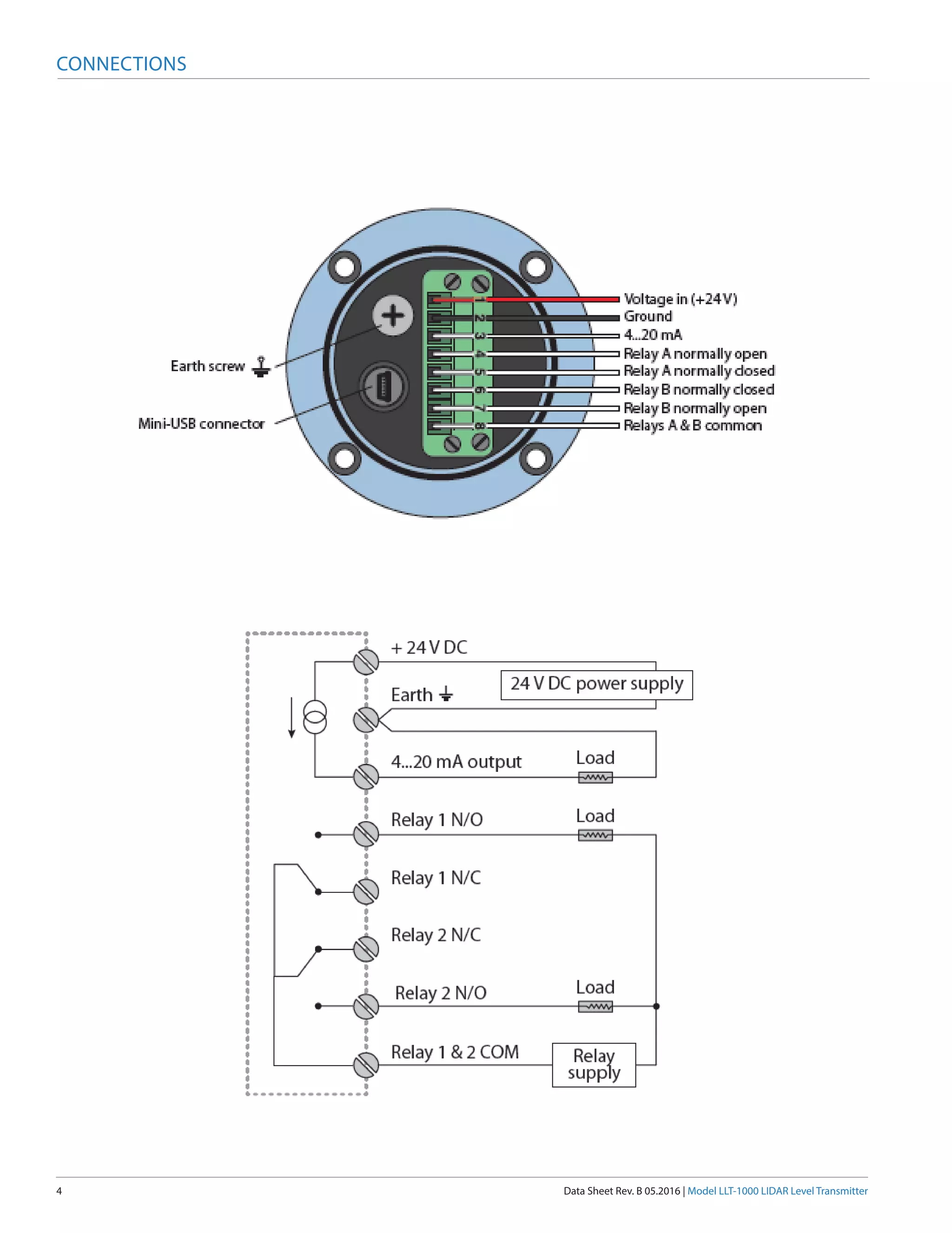

The LLT-1000 Lidar Level Transmitter is a non-contact, laser-based device designed for measuring levels in various applications with high accuracy and long measurement ranges. It features 4-20 mA and relay interfaces for control, a USB interface for configuration, and optional visible aiming laser capabilities. The transmitter operates using time-of-flight laser technology, providing reliable measurements irrespective of environmental conditions while maintaining ease of use through local programming options.


