Lab view study of electrical power distribution system
•
1 like•339 views

IJRET : International Journal of Research in Engineering and Technology is an international peer reviewed, online journal published by eSAT Publishing House for the enhancement of research in various disciplines of Engineering and Technology. The aim and scope of the journal is to provide an academic medium and an important reference for the advancement and dissemination of research results that support high-level learning, teaching and research in the fields of Engineering and Technology. We bring together Scientists, Academician, Field Engineers, Scholars and Students of related fields of Engineering and Technology

Recommended
Recommended
More Related Content
What's hot
What's hot (20)
Viewers also liked
Viewers also liked (20)
Similar to Lab view study of electrical power distribution system
Similar to Lab view study of electrical power distribution system (20)
More from eSAT Publishing House
More from eSAT Publishing House (20)
Recently uploaded
Recently uploaded (20)
Lab view study of electrical power distribution system
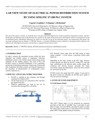
- 1. IJRET: International Journal of Research in Engineering and Technology eISSN: 2319-1163 | pISSN: 2321-7308 __________________________________________________________________________________________ Volume: 03 Issue: 04 | Apr-2014, Available @ http://www.ijret.org 142 LAB VIEW STUDY OF ELECTRICAL POWER DISTRIBUTION SYSTEM BY USING SIMATIC S7-300 PLC SYSTEM Yogesh.Y.Gajbhiye1 , P.Pjagtap2 , J.B.Helonde3 1 M.TECH IPS, Electrical Department, G.H.Raisoni college of Engineering 2 Assist.Prof in EE, Electrical Department, G.H.Raisoni college of Engineering 3 Principal of ITM college of Engineering, Nagpur, India Abstract The aim of this paper is, firstly, to recall the basic concepts of SCADA (Supervisory Control and Data Acquisition) systems, and how Scada plays an important role in the field of power system. for the study of electrical power distribution system we need general set-up of automated power distribution laboratory in which we need the set-up of one generator panel, one transmission line panel, one receiving end panel and one Simatic s7 300 PLC System. a versatile distribution system simulator is developed which replicates the behavior of a distribution network as viewed from a computer based control centre. Keywords: Simatic s7 300 PLC System, SCADA and electrical power distribution system ------------------------------------------------------------------------***---------------------------------------------------------------------- 1. INTRODUCTION In today’s scenario the automation system exhibit the most important and reliable system to implement. Electrical distribution system is the volatile system which always needs reliability for the stability purpose. The need of PLC and SCADA system to electrical distribution is for controlling, monitoring of distribution parameter. Supervisory Control and Data Acquisition (SCADA) systems are critically important to the procedure of Modernization of contemporary power systems, industries etc. 2. HOW PLC AND SCADA WORK TOGETHER o SCADA is installed in the computers and through serial port it is linked to PLC . o All the field devices are connected to PLC and they get signals from PLC. o Whatever applications we want to run can be executed either through PLC or SCADA. Block Diagram : 4 Field Equipments Transducer & Meters PLC SCADA To web server PLC basically senses input from the field (using its input cards), example: - a level sensor, a proximity switch, push button etc. Depending on the logic written in the PLC logic memory, Certain decision are taken by the PLC (using CPU card and logic card).Based on the decision taken, certain output, like contactors (for driving motors), solenoids (for linear movement), lamps (for indications), valves (for flow control) etc, are driven by the PLC. SCADA receive the signal from PLC output. if some part in the power system are unhealthy the SCADA gives signal to PLC for recovery of damage. 3. STUDY OF PANEL/EQUIPMENT 3.1 Grid Source Panel 440 VOLT 3phase input is to be connected on connector provided on left side of unit.HRC fuse is provided in each phase at input. Four pole MCB is provided on panel to isolate the system from mains Source A and Source B are two three phase 440V/5Amp supplies acting as Generator.
- 2. IJRET: International Journal of Research in Engineering and Technology eISSN: 2319-1163 | pISSN: 2321-7308 __________________________________________________________________________________________ Volume: 03 Issue: 04 | Apr-2014, Available @ http://www.ijret.org 143 Grid source panel displays Voltage Vry, Vyb and Vbr and three phase current Ir, Iy and Ib on respective meters for both source A and source B. Also for source A sending end power factor is displayed on power factor meter. voltage selector switch is to be used to display Vry,Vyb and Vbr voltage. Power line Sensors: For source A voltage sensors for Vry, Vyb and Vbr, three current sensors for Ir,Iy and Ib and one 3P/3E/4W-trms power factor sensor is provided on sending end. also for source B three current sensors is provided on sending end. 3.2 Busbar with Simulated Transmission Line Two parallel Bus Bar A and B with 5A rating. Each BusBar is having three sections. BUSBAR WITH SIMULATED TRANSMISSION LINE Section A: Simulated transmission line representing 50 KM long (one unit) Section B: Simulated transmission line representing 150 KM long (three unit) Section C: Simulated transmission line representing 200 KM long (four unit) 3.3 Contactor Connection When contactor Q1 is on, BusBar A is charged (section 1 only) for respective sections of BusBar A, corresponding contactor must be on. When contactor Q5 is on, BusBar B is charged. 3.4 Receiving End Panel Load 1 Receiving End panel displays Voltage Vry, Vyb and Vbr and three phase current Ir, Iy and Ib on respective meters. Voltage selector switch is to be used to display Vry, Vyb and Vbr voltage. SENTRON PACK 3200-Power analyzer is provided on panel at L1. Load 2 Receiving End panel displays Voltage Vry, Vyb and Vbr voltage. Load is to be connector provided on panel at L2. 3.5 Siemens Simatic S7 300 PLC Setup
- 3. IJRET: International Journal of Research in Engineering and Technology eISSN: 2319-1163 | pISSN: 2321-7308 __________________________________________________________________________________________ Volume: 03 Issue: 04 | Apr-2014, Available @ http://www.ijret.org 144 It is connected from engineering station (pc) with IP address 192.168.0.1 to CPU 314C-2PN DPALON WITH SENTRON PACK 3200 POWER ANALYSER. CPU AND POWER ANALYSER is connected with power modules. 4. PROGRAMMING FOR ELECTRICAL POWER DISTRIBUTION SCADA SYSTEM Network 2: Network 4: Network 5: Network 7:
- 4. IJRET: International Journal of Research in Engineering and Technology eISSN: 2319-1163 | pISSN: 2321-7308 __________________________________________________________________________________________ Volume: 03 Issue: 04 | Apr-2014, Available @ http://www.ijret.org 145 Network 10: Network 12: Network 14:
- 5. IJRET: International Journal of Research in Engineering and Technology eISSN: 2319-1163 | pISSN: 2321-7308 __________________________________________________________________________________________ Volume: 03 Issue: 04 | Apr-2014, Available @ http://www.ijret.org 146 Network 19: Network 21: Network 24:
- 6. IJRET: International Journal of Research in Engineering and Technology eISSN: 2319-1163 | pISSN: 2321-7308 __________________________________________________________________________________________ Volume: 03 Issue: 04 | Apr-2014, Available @ http://www.ijret.org 147 Network 29: Network 33:
- 7. IJRET: International Journal of Research in Engineering and Technology eISSN: 2319-1163 | pISSN: 2321-7308 __________________________________________________________________________________________ Volume: 03 Issue: 04 | Apr-2014, Available @ http://www.ijret.org 148 Network 35: 4. EXPERIMENTAL RESULT 4.1 4.2 To Study voltage regulation of transmission line Load type V ry V yb V br Ir Iy Ib R 427 423 425 2.25 2.14 2.07 R-L 429 424 427 2.97 2.75 2.59 R-L- C 428 423 424 2.30 2.24 2.19 Vry Vyb Vbr Ir Iy Ib 407 407 407 2.09 2.09 2.03 373 367 370 2.97 2.99 2.81 400 395 397 2.19 2.27 2.21 Sending end Receiving end CALCULATION • % VOLTAGE REGULATION ={ (Vs-Vr)/Vr} x 100 • For R load ={(427-407)/407} x 100 • = 4.914 • For R-L load ={(429-373)/373} x 100 • =15.01 • For R-L-C load ={(428-400)/400} x 100 • =7 4.3 Fault Create on Various Section of Busbar VIEW FAULT STATUS IN WINCC SCADA SOFTWARE
- 8. IJRET: International Journal of Research in Engineering and Technology eISSN: 2319-1163 | pISSN: 2321-7308 __________________________________________________________________________________________ Volume: 03 Issue: 04 | Apr-2014, Available @ http://www.ijret.org 149 For creating Fault on Section 2 by using LG Fault selector switch We can see the fault in section 2.Contactor Q2 and Q3 are off and Contactor Q6 and Q9 are on for Maintain continuity of supply of Power Distribution 5. APPLICATION OF SCADA TO ELECTRIC POWER DISTRIBUTION SYSTEMS A reliable power distribution system is an essential Component for the economic growth and development of a country. Therefore, a modern electric power network system must be capable of performing 365 days a year and 24 hours a day with a high quality of uninterrupted power supply, even during the peak hours, to improve the performance of services to the customers. In view of the extensive size of the distribution networks, this can be achieved only by proper computer-based monitoring and control system as well as by efficient distribution and metering. The "Monitoring and Control System" is the main part of a distribution automation network. This system was defined by IEEE as "A system that enables an electric company to remotely monitor, coordinate and operate distribution components in a real-time mode from remote location”. The location from where control decisions are initiated is generally called Distribution Control Center (DCC).Within this center, different kinds of application software are used, which cooperate among themselves to achieve the control task. In this discussion we would mainly focus on the customer service quality. Customer service requirements point to one key element: Information, i.e., the right amount of information to the right person or computer within the right amount of time. The flow of information requires data communication over extended networks of systems and users. In fact, utilities are becoming among the largest users of data and are the largest users of real-time information Hence, the implementation of power network automation system will provide better services to EDC customers and improve the power quality and reliability of the electric supply services, which would satisfy the following goals: Respond to customer service interruptions morequickly. More efficiency of the power system by maintaining acceptable power factors and reduced losses. More control and limit of peak power demand. Ability of EDC engineering staff to monitor andcontrol the power system during normal and abnormal conditions by providing more reliable and appropriate real time data Ability of EDC engineering staff to perform the power system analysis and planning by providing increased access to past and current operations data and associated software tools Ability of EDC engineering staff to manage the power system assets and system operations by providing increased access to better performance data and historical statistics 6. CONCLUSIONS In this paper, we present a computer based power distribution automation system is discussed. Moreover, we proved the importance on using computer based system for sustainable development in the automation of the power distribution network to improve the service and the reliability of the network. Also the paper outlines the general concepts and required equipments for the automation of such power networks. REFERENCES [1]. M.M Ahmed” Development Of Automated Fault Isolation System On Distribution Systems In Malaysia”, ICCCE 2012, 3-5 JULY 2012 Malaysia Kawla Lumpur [2]. M.M Ahmed and S.Lian ‘’Novel Automated Fault Isolation on Low Voltage Distribution Automation System’’, 2013 UkSim 15th International Conference on Computer Modeling and Simulation. bly” 978-1-4577-0547-2/12/$31.00 ©2012 IEEE [3]. I.N Fovino and M. Masera” An Experimental Platform for Assessing SCADA Vulnerabilities and Countermeasures in Power Plants” Rzeszow, poland may 13-15, 2010 [4]. J. Marcuse, B. Menz and J.R. Payne, Servers in SCADA applications, IEEE Trans. Ind. Appl" 9 -2, 1997, pp 12951334 [5]. E.K. Chan and H. Ebenhon, The implementation and Evolution of a SCADA System for a Large Distribution Network, "IEEE Transactions on Power systems", Vol.7, No.1, [6]. H.L. Poon, Applications of Data Acquisition Systems, "Computers in Industry" 13, 1989, pp 49-59. [7]. E. Ozdemir and M. Karacor, Mobile phone based SCADA for industrial automation, "ISA Transactions", vol.45, Num 1, January 2006, pp 67–75. [8]. J.H. Horng, SCADA system of DC motor with implementation of fuzzy logic controller on neural network, "Advances in Engineering Software. 1992, pp.320-326 [9]. S.MALI and P.Suresh”Automated power distribution simulator "Electrical and Computer Engineering, 1996. Canadian Conference [10]. Jinjun Zheng and Chuanxue Song”Experimental study on transmission efficiency of hybrid electric bus transmission with synthetic box assem BIOGRAPHIES Mr. Yogesh y. Gajbhiye was born on 23/03/1984 in Nagpur, India. He completed his B.E in Electrical from Government College of Engineering Chandrapur in 2009. Now currently pursuing his M.tech from G.H.RAISONI COLLEGE NAGPUR (AUTONOMOUS) and working as a Teaching Assistant in same college. His Research interest in power system
- 9. IJRET: International Journal of Research in Engineering and Technology eISSN: 2319-1163 | pISSN: 2321-7308 __________________________________________________________________________________________ Volume: 03 Issue: 04 | Apr-2014, Available @ http://www.ijret.org 150 Prof. Prashant.p.Jagtap working as a Assist.Prof in G.H.RAISONI COLLEGE NAGPUR(AUTONOMOUS).He pursuing his PHD from Nagpur University.His Research interest in the field of Power System, FACTS. Dr J.B.HELONDE working as a Principal of ITM college of Engineering Nagpur Maharashtra. His Research interest in the field of Power System and FACTS.