Lab Report 1
•Download as DOCX, PDF•
0 likes•205 views
This lab report summarizes an experiment to map electric field lines and equipotentials. Students set up an apparatus with a power supply, resistive paper, pins and alligator clips. They measured voltages at various points on the paper to find equipotentials and calculated the electric field from the voltage differences and distances. Their results showed symmetrical equipotential graphs and electric field lines perpendicular to equipotentials as expected. Calculated electric fields were in the expected range but some error was introduced by equipment limitations and measurement inaccuracies.
Report
Share
Report
Share

Recommended
2) Resistance and Ohm's Law
1) Current is the flow of electrons through a conductor and is measured in Amperes. It flows from the positive terminal to the negative terminal in a circuit with a potential difference.
2) Alternating current changes direction periodically while direct current flows in only one direction. AC is preferred for transmission due to lower energy losses while DC is used for applications like batteries.
3) A resistor limits current flow in a circuit. It offers resistance and converts voltage to heat energy. Resistors are used to control current and divide voltages in a circuit. Their values can be determined using color codes.
Determination of charge to mass ratio of an electron
The document describes an experiment to measure the charge-to-mass ratio (e/m) of electrons by observing their trajectories in a uniform magnetic field. It provides the objectives, a brief history of previous measurements, equipment needed including an e/m apparatus, safety considerations, procedures for data acquisition including varying the accelerating voltage and magnetic field strength and measuring the electron beam radius, and plans for analysis including calculating e/m from measurements and comparing to the accepted value.
1) Battery
This document provides information about batteries as an energy source for experiments. It discusses that batteries convert chemical energy to electrical energy and provide direct current (DC) power in a portable and low-cost form. It then gives specifications for a common 9V battery, explaining voltage as electrical force and potential difference between positive and negative terminals. It also describes how to measure the voltage of a battery using a digital multimeter by connecting the probes to the battery terminals and selecting the appropriate voltage range.
8) Circuit Combinations
- Electrical devices like air conditioners, fans, and refrigerators consume power to do useful work. They can be connected in either series or parallel configurations.
- In a series configuration, the current through each device is the same and the total voltage is divided among all devices. If one device is faulty, it creates an open circuit condition.
- In a parallel configuration, the voltage across each device is the same but the current can vary. If one device is faulty, the others will still work as long as the power source can handle the current drawn.
Phys 102 formal simple dc circuits lab report
In this lab experiment, the student built both series and parallel circuits containing three resistors each to investigate the relationships between resistance, potential difference, and current. For the series circuit, the student found that the current remains the same throughout while the potential difference varies across each resistor. For the parallel circuit, the current varies across each resistor while the potential difference remains the same. The student's measurements matched well with theoretical calculations, validating the circuit concepts.
3 e electronics 091210
1) The document describes setting up a circuit with a resistor and power supply to take voltage and current readings at different voltages.
2) It involves plotting a graph of voltage vs. current and determining the gradient, which represents resistance. Ohm's law that voltage equals current times resistance is also covered.
3) Resistors are used to control current and voltage in circuits. Their properties in series and parallel circuits are discussed.
10) Capacitors
Capacitors are energy storage devices that can temporarily store and release electric charge. They consist of two conductive plates separated by an insulating material. The capacitance, or ability to store charge, depends on the distance between plates, the area of the plates, and the material between them. There are two main types - electrolytic capacitors, which have a polarity, and ceramic capacitors, which do not. Capacitors can be charged by applying a voltage across their terminals and discharged by shorting the terminals.
An Experiment to Verify Ohm's Law
This document summarizes an experiment conducted by Vania Lundina to verify how the length of a conductor affects its resistance according to Ohm's Law. The experiment involved measuring the resistance of copper wires of varying lengths (10-35 cm) using a voltmeter, ammeter, and power supply. The results showed that resistance increased with increasing length, supporting the conclusion that resistance is directly proportional to length as predicted by Ohm's Law. Some variability between trials was attributed to inaccuracies in measuring wire length.
Ohms law
Dear student, Cheap Assignment Help, an online tutoring company, provides students with a wide range of online assignment help services for students studying in classes K-12, and College or university. The Expert team of professional online assignment help tutors at Cheap Assignment Help .COM provides a wide range of help with assignments through services such as college assignment help, university assignment help, homework assignment help, email assignment help and online assignment help. Our expert team consists of passionate and professional assignment help tutors, having masters and PhD degrees from the best universities of the world, from different countries like Australia, United Kingdom, United States, Canada, UAE and many more who give the best quality and plagiarism free answers of the assignment help questions submitted by students, on sharp deadline. Cheap Assignment Help .COM tutors are available 24x7 to provide assignment help in diverse fields - Math, Chemistry, Physics, Writing, Thesis, Essay, Accounting, Finance, Data Analysis, Case Studies, Term Papers, and Projects etc. We also provide assistance to the problems in programming languages such as C/C++, Java, Python, Matlab, .Net, Engineering assignment help and Finance assignment help. The expert team of certified online tutors in diverse fields at Cheap Assignment Help .COM available around the clock (24x7) to provide live help to students with their assignment and questions. We have also excelled in providing E-education with latest web technology. The Students can communicate with our online assignment tutors using voice, video and an interactive white board. We help students in solving their problems, assignments, tests and in study plans. You will feel like you are learning from a highly skilled online tutor in person just like in classroom teaching. You can see what the tutor is writing, and at the same time you can ask the questions which arise in your mind. You only need a PC with Internet connection or a Laptop with Wi-Fi Internet access. We provide live online tutoring which can be accessed at anytime and anywhere according to student’s convenience. We have tutors in every subject such as Math, Chemistry, Biology, Physics and English whatever be the school level. Our college and university level tutors provide engineering online tutoring in areas such as Computer Science, Electrical and Electronics engineering, Mechanical engineering and Chemical engineering. Regards http://www.cheapassignmenthelp.com/ http://www.cheapassignmenthelp.co.uk/
Lab 2
This document describes an experiment on Ohm's Law conducted by students at Palestine Polytechnic University. The objectives are to study the relationship between current (I) and potential difference (V) across a resistor and determine resistance using Ohm's Law. Equipment used includes a digital multimeter, ammeter, wires, power supply and circuit board. Calculations show the linear relationship between current, voltage and resistance. The experiment involves three exercises to determine circuit resistance, current and voltage using Ohm's Law. In conclusion, Ohm's Law states voltage is directly proportional to current if temperature remains constant, and the relationships can be verified using ohmmeters, color codes and ammeters/voltmeters.
Long report fizik
This document summarizes an experiment on Ohm's Law and finding the resistance of unknown resistors. In part A, the resistance was held constant at 100 ohms while the voltage was varied from 3V to 12V to measure current. Then voltage was held at 10V while resistance was varied to measure current. The measured values aligned well with theoretical calculations using Ohm's Law. In part B, resistors of varying values were used in series and the current and reciprocal of current were measured and graphed. The graph's slope provided the resistance and the y-intercept was zero, confirming Ohm's Law. Minor differences between measured and theoretical values were due to factors like resistor degradation over multiple uses.
6 d electronics 061210
This document discusses using a Wheatstone bridge circuit to measure resistance. It provides instructions on how to set up the circuit with 3 known resistors and 1 unknown resistor. When balanced, the voltmeter will read 0 and the resistance values can be used to calculate the unknown resistance. It notes that when slightly imbalanced, the voltmeter reading is directly proportional to the change in resistance, allowing it to be used as a measuring device near the balance point.
Resistors measurement in series and parallel circuits
This document discusses resistors in series and parallel circuits. It explains that to calculate current or voltage, the total resistance must first be determined. For resistors in series, the total resistance is equal to the sum of the individual resistances. For resistors in parallel, the total resistance is calculated by taking the reciprocal of the sum of the reciprocals of the individual resistances, which is always smaller than any single resistance. Sample problems are provided for calculating total resistance and current in both series and parallel circuits.
SERIES RESISTOR-CAPASITOR CIRCUIT experiment 7
1. The document describes an experiment on analyzing series resistor-capacitor circuits. The objective is to understand the relationship between voltage, current, and phase angle and to calculate the phase angle.
2. Key aspects of the series RC circuit are discussed, including how impedance is calculated as the sum of resistance and capacitive reactance. The voltage and current relationships show the current is in phase with voltage across the resistor but lags the voltage across the capacitor by 90 degrees.
3. The experiment involves measuring voltages and calculating phase angles for different capacitors in a series RC circuit. Results show the phase angle depends on the capacitor value, with smaller capacitors producing larger phase angles. Errors in measurements
Lab 07 voltage_current_divider
This document describes experiments on voltage and current dividers. Students will build divider circuits using resistors and a power supply. They will measure voltages and currents, record results, and calculate theoretical values to validate formulas for output voltage and current based on resistor values. Questions address what would happen if a resistor was replaced by a short or open circuit, and the accuracy of measurements.
Balances
1. Balances are instruments that measure mass using gravity to act on an object. There are two main types: mechanical balances using springs or sliding weights, and electronic balances using load cells or electromagnetic force.
2. Electronic balances operate using either a load cell that detects strain to measure weight, or an electromagnetic force restoration method that precisely measures current needed to balance a lever.
3. Routine maintenance of balances includes verifying level and zero settings, cleaning weighing surfaces, and annual calibration. Faults like unstable readings may result from the balance not being leveled or calibrated correctly.
1.7.4 Example 2
Two resistors are connected in series to an AC source. The RMS voltage across one resistor is 6.5V and across the other is 3.2V. To calculate the peak source voltage, the RMS voltages are summed and then converted to peak voltage by multiplying by 1.414. The calculated peak source voltage is 13.72V.
Qp
This document contains a physics test with multiple choice and long answer questions covering topics in electricity and electromagnetism. The test is divided into 5 parts (A-E) testing concepts such as Coulomb's law, electric fields, electric potential, capacitance, resistors, Kirchhoff's laws, and more. Students are asked to define terms, derive equations, sketch diagrams, and solve problems involving electric forces, fields, potential, capacitors, and circuits.
Wheatstone bridge
The Wheatstone bridge is a circuit invented in 1833 by Samuel Hunter Christie to measure an unknown electrical resistance. It uses a galvanometer to monitor a balanced state where no current flows through the galvanometer (ig=0). By adjusting variable resistors to reach this balanced state, the mathematical ratio of the arms can be used to calculate the fourth unknown resistance. The Wheatstone bridge found many applications in measuring strain, locating breaks in power lines, and indirectly measuring other variables that impact electrical resistance, such as temperature, force, and pressure.
Wheatstone Bridge in Lab
This is the Lab report on the subject of instrumentation where we have observed how to find the unknown resistance using the DYNA-1750 and hence help us to find more things.
17 resistance in series and parallel
The document discusses resistance in series and parallel circuits. For series circuits, the total resistance (Rs) is calculated by adding the individual resistances. For parallel circuits, the total resistance (Rp) is calculated by taking the reciprocal of the sum of the reciprocals of the individual resistances. An example is provided showing how to calculate the equivalent resistance of two light bulbs connected in parallel.
3 e electronics 301110
The document discusses resistance and Ohm's law. It describes setting up a circuit with a resistor and power supply to take voltage and current measurements. By plotting the measurements on a graph and calculating the gradient, resistance can be determined using the equation R=V/I. Resistance is measured in Ohms and represents an object's opposition to electric current. Ohm's law states that voltage equals current times resistance. Resistors are used to control current and voltage in circuits. Power dissipated in a resistor is calculated using P=IV or P=I^2R. Resistors in series increase total resistance while resistors in parallel decrease total resistance.
Wheatstone Bridge
This document describes the construction and application of a Wheatstone bridge circuit. It begins by introducing Wheatstone bridges and their inventor. It then discusses the key components of a Wheatstone bridge, including four resistors where one has an unknown value. The working principle is explained, where balancing the resistor ratios results in no current through the galvanometer. Example circuits are provided. Applications include measuring light, pressure, strain and more. Limitations include inaccuracies under unbalanced conditions and limited resistance ranges.
Wheatstone bridge
This practicum report describes experiments using a Wheatstone bridge circuit to determine unknown resistor values. The objectives are to determine resistor values indirectly and more accurately compared to using Ohm's law alone. Two experiments are conducted to find unknown resistor values paired with resistors of known values. The first experiment estimates the unknown resistor at 85.71 ohms and the second at 15.67 ohms. Some error is observed in the measurements. The report concludes by discussing sources of error and reviewing the application of Wheatstone bridge principles.
Capacitor and Capacitance
The document discusses capacitors and capacitance. It defines a capacitor as a device that stores electric potential energy and electric charge using two conductors separated by an insulator. It explains the concepts of capacitance, capacitors in series and parallel, and provides examples of calculating capacitance and stored energy for parallel plate capacitors.
Single diode circuits
This document discusses single diode circuits and the diode equation. It provides:
1) The diode equation that relates diode current (iD) to voltage (vD) through saturation current (IS), temperature, and other constants.
2) Typical values for the variables in the diode equation.
3) An example problem that demonstrates calculating diode voltage and current given circuit specifications by applying Kirchhoff's law and the diode equation.
Dc bridge types ,derivation and its application
The DC Bridge is used for measuring the unknown electrical resistance. This can be done by balancing the two legs of the bridge circuit. The value of one of the arm is known while the other of them is unknown
Lab questions
This lab report examines the electric field around a conductor using conductive paper. The student sketches the electric field lines and equipotential lines for two point charges and a parallel plate configuration. Most results support the predictions, though some lines are not perpendicular, possibly due to static charge on the paper or interference from the pencil. The density of equipotential lines, electric field lines, and electric field strength are related - as one increases, so do the others. Introducing a hand near the paper would ground it, altering measurements. The introduction outlines measuring electric fields and equipotentials, while the conclusion notes that objectives were met but with some mechanical errors.
Sinusoidal Response of RC & RL Circuits
This document describes an experiment on analyzing the sinusoidal responses of RC and RL circuits. RC and RL circuits were constructed using a breadboard, resistors, capacitors, inductors, function generator, oscilloscope and multimeter. Experimental measurements of output voltage, phase shift, and resistor current were taken at various frequencies and compared to theoretical calculations. The results showed close agreement between measured and calculated output voltages, but more discrepancy for RMS voltages, possibly due to experimental or calculation errors.
More Related Content
What's hot
An Experiment to Verify Ohm's Law
This document summarizes an experiment conducted by Vania Lundina to verify how the length of a conductor affects its resistance according to Ohm's Law. The experiment involved measuring the resistance of copper wires of varying lengths (10-35 cm) using a voltmeter, ammeter, and power supply. The results showed that resistance increased with increasing length, supporting the conclusion that resistance is directly proportional to length as predicted by Ohm's Law. Some variability between trials was attributed to inaccuracies in measuring wire length.
Ohms law
Dear student, Cheap Assignment Help, an online tutoring company, provides students with a wide range of online assignment help services for students studying in classes K-12, and College or university. The Expert team of professional online assignment help tutors at Cheap Assignment Help .COM provides a wide range of help with assignments through services such as college assignment help, university assignment help, homework assignment help, email assignment help and online assignment help. Our expert team consists of passionate and professional assignment help tutors, having masters and PhD degrees from the best universities of the world, from different countries like Australia, United Kingdom, United States, Canada, UAE and many more who give the best quality and plagiarism free answers of the assignment help questions submitted by students, on sharp deadline. Cheap Assignment Help .COM tutors are available 24x7 to provide assignment help in diverse fields - Math, Chemistry, Physics, Writing, Thesis, Essay, Accounting, Finance, Data Analysis, Case Studies, Term Papers, and Projects etc. We also provide assistance to the problems in programming languages such as C/C++, Java, Python, Matlab, .Net, Engineering assignment help and Finance assignment help. The expert team of certified online tutors in diverse fields at Cheap Assignment Help .COM available around the clock (24x7) to provide live help to students with their assignment and questions. We have also excelled in providing E-education with latest web technology. The Students can communicate with our online assignment tutors using voice, video and an interactive white board. We help students in solving their problems, assignments, tests and in study plans. You will feel like you are learning from a highly skilled online tutor in person just like in classroom teaching. You can see what the tutor is writing, and at the same time you can ask the questions which arise in your mind. You only need a PC with Internet connection or a Laptop with Wi-Fi Internet access. We provide live online tutoring which can be accessed at anytime and anywhere according to student’s convenience. We have tutors in every subject such as Math, Chemistry, Biology, Physics and English whatever be the school level. Our college and university level tutors provide engineering online tutoring in areas such as Computer Science, Electrical and Electronics engineering, Mechanical engineering and Chemical engineering. Regards http://www.cheapassignmenthelp.com/ http://www.cheapassignmenthelp.co.uk/
Lab 2
This document describes an experiment on Ohm's Law conducted by students at Palestine Polytechnic University. The objectives are to study the relationship between current (I) and potential difference (V) across a resistor and determine resistance using Ohm's Law. Equipment used includes a digital multimeter, ammeter, wires, power supply and circuit board. Calculations show the linear relationship between current, voltage and resistance. The experiment involves three exercises to determine circuit resistance, current and voltage using Ohm's Law. In conclusion, Ohm's Law states voltage is directly proportional to current if temperature remains constant, and the relationships can be verified using ohmmeters, color codes and ammeters/voltmeters.
Long report fizik
This document summarizes an experiment on Ohm's Law and finding the resistance of unknown resistors. In part A, the resistance was held constant at 100 ohms while the voltage was varied from 3V to 12V to measure current. Then voltage was held at 10V while resistance was varied to measure current. The measured values aligned well with theoretical calculations using Ohm's Law. In part B, resistors of varying values were used in series and the current and reciprocal of current were measured and graphed. The graph's slope provided the resistance and the y-intercept was zero, confirming Ohm's Law. Minor differences between measured and theoretical values were due to factors like resistor degradation over multiple uses.
6 d electronics 061210
This document discusses using a Wheatstone bridge circuit to measure resistance. It provides instructions on how to set up the circuit with 3 known resistors and 1 unknown resistor. When balanced, the voltmeter will read 0 and the resistance values can be used to calculate the unknown resistance. It notes that when slightly imbalanced, the voltmeter reading is directly proportional to the change in resistance, allowing it to be used as a measuring device near the balance point.
Resistors measurement in series and parallel circuits
This document discusses resistors in series and parallel circuits. It explains that to calculate current or voltage, the total resistance must first be determined. For resistors in series, the total resistance is equal to the sum of the individual resistances. For resistors in parallel, the total resistance is calculated by taking the reciprocal of the sum of the reciprocals of the individual resistances, which is always smaller than any single resistance. Sample problems are provided for calculating total resistance and current in both series and parallel circuits.
SERIES RESISTOR-CAPASITOR CIRCUIT experiment 7
1. The document describes an experiment on analyzing series resistor-capacitor circuits. The objective is to understand the relationship between voltage, current, and phase angle and to calculate the phase angle.
2. Key aspects of the series RC circuit are discussed, including how impedance is calculated as the sum of resistance and capacitive reactance. The voltage and current relationships show the current is in phase with voltage across the resistor but lags the voltage across the capacitor by 90 degrees.
3. The experiment involves measuring voltages and calculating phase angles for different capacitors in a series RC circuit. Results show the phase angle depends on the capacitor value, with smaller capacitors producing larger phase angles. Errors in measurements
Lab 07 voltage_current_divider
This document describes experiments on voltage and current dividers. Students will build divider circuits using resistors and a power supply. They will measure voltages and currents, record results, and calculate theoretical values to validate formulas for output voltage and current based on resistor values. Questions address what would happen if a resistor was replaced by a short or open circuit, and the accuracy of measurements.
Balances
1. Balances are instruments that measure mass using gravity to act on an object. There are two main types: mechanical balances using springs or sliding weights, and electronic balances using load cells or electromagnetic force.
2. Electronic balances operate using either a load cell that detects strain to measure weight, or an electromagnetic force restoration method that precisely measures current needed to balance a lever.
3. Routine maintenance of balances includes verifying level and zero settings, cleaning weighing surfaces, and annual calibration. Faults like unstable readings may result from the balance not being leveled or calibrated correctly.
1.7.4 Example 2
Two resistors are connected in series to an AC source. The RMS voltage across one resistor is 6.5V and across the other is 3.2V. To calculate the peak source voltage, the RMS voltages are summed and then converted to peak voltage by multiplying by 1.414. The calculated peak source voltage is 13.72V.
Qp
This document contains a physics test with multiple choice and long answer questions covering topics in electricity and electromagnetism. The test is divided into 5 parts (A-E) testing concepts such as Coulomb's law, electric fields, electric potential, capacitance, resistors, Kirchhoff's laws, and more. Students are asked to define terms, derive equations, sketch diagrams, and solve problems involving electric forces, fields, potential, capacitors, and circuits.
Wheatstone bridge
The Wheatstone bridge is a circuit invented in 1833 by Samuel Hunter Christie to measure an unknown electrical resistance. It uses a galvanometer to monitor a balanced state where no current flows through the galvanometer (ig=0). By adjusting variable resistors to reach this balanced state, the mathematical ratio of the arms can be used to calculate the fourth unknown resistance. The Wheatstone bridge found many applications in measuring strain, locating breaks in power lines, and indirectly measuring other variables that impact electrical resistance, such as temperature, force, and pressure.
Wheatstone Bridge in Lab
This is the Lab report on the subject of instrumentation where we have observed how to find the unknown resistance using the DYNA-1750 and hence help us to find more things.
17 resistance in series and parallel
The document discusses resistance in series and parallel circuits. For series circuits, the total resistance (Rs) is calculated by adding the individual resistances. For parallel circuits, the total resistance (Rp) is calculated by taking the reciprocal of the sum of the reciprocals of the individual resistances. An example is provided showing how to calculate the equivalent resistance of two light bulbs connected in parallel.
3 e electronics 301110
The document discusses resistance and Ohm's law. It describes setting up a circuit with a resistor and power supply to take voltage and current measurements. By plotting the measurements on a graph and calculating the gradient, resistance can be determined using the equation R=V/I. Resistance is measured in Ohms and represents an object's opposition to electric current. Ohm's law states that voltage equals current times resistance. Resistors are used to control current and voltage in circuits. Power dissipated in a resistor is calculated using P=IV or P=I^2R. Resistors in series increase total resistance while resistors in parallel decrease total resistance.
Wheatstone Bridge
This document describes the construction and application of a Wheatstone bridge circuit. It begins by introducing Wheatstone bridges and their inventor. It then discusses the key components of a Wheatstone bridge, including four resistors where one has an unknown value. The working principle is explained, where balancing the resistor ratios results in no current through the galvanometer. Example circuits are provided. Applications include measuring light, pressure, strain and more. Limitations include inaccuracies under unbalanced conditions and limited resistance ranges.
Wheatstone bridge
This practicum report describes experiments using a Wheatstone bridge circuit to determine unknown resistor values. The objectives are to determine resistor values indirectly and more accurately compared to using Ohm's law alone. Two experiments are conducted to find unknown resistor values paired with resistors of known values. The first experiment estimates the unknown resistor at 85.71 ohms and the second at 15.67 ohms. Some error is observed in the measurements. The report concludes by discussing sources of error and reviewing the application of Wheatstone bridge principles.
Capacitor and Capacitance
The document discusses capacitors and capacitance. It defines a capacitor as a device that stores electric potential energy and electric charge using two conductors separated by an insulator. It explains the concepts of capacitance, capacitors in series and parallel, and provides examples of calculating capacitance and stored energy for parallel plate capacitors.
Single diode circuits
This document discusses single diode circuits and the diode equation. It provides:
1) The diode equation that relates diode current (iD) to voltage (vD) through saturation current (IS), temperature, and other constants.
2) Typical values for the variables in the diode equation.
3) An example problem that demonstrates calculating diode voltage and current given circuit specifications by applying Kirchhoff's law and the diode equation.
Dc bridge types ,derivation and its application
The DC Bridge is used for measuring the unknown electrical resistance. This can be done by balancing the two legs of the bridge circuit. The value of one of the arm is known while the other of them is unknown
What's hot (20)
Resistors measurement in series and parallel circuits
Resistors measurement in series and parallel circuits
Similar to Lab Report 1
Lab questions
This lab report examines the electric field around a conductor using conductive paper. The student sketches the electric field lines and equipotential lines for two point charges and a parallel plate configuration. Most results support the predictions, though some lines are not perpendicular, possibly due to static charge on the paper or interference from the pencil. The density of equipotential lines, electric field lines, and electric field strength are related - as one increases, so do the others. Introducing a hand near the paper would ground it, altering measurements. The introduction outlines measuring electric fields and equipotentials, while the conclusion notes that objectives were met but with some mechanical errors.
Sinusoidal Response of RC & RL Circuits
This document describes an experiment on analyzing the sinusoidal responses of RC and RL circuits. RC and RL circuits were constructed using a breadboard, resistors, capacitors, inductors, function generator, oscilloscope and multimeter. Experimental measurements of output voltage, phase shift, and resistor current were taken at various frequencies and compared to theoretical calculations. The results showed close agreement between measured and calculated output voltages, but more discrepancy for RMS voltages, possibly due to experimental or calculation errors.
Gamma Ray Spectroscopy Report
The document summarizes a gamma ray spectroscopy lab experiment. Key findings include:
- Gamma rays from various radioactive samples were measured using a sodium iodide detector and spectrometer interface.
- A linear relationship was found between the gamma ray energies and their channel numbers on the spectrometer.
- All major gamma ray interactions (photoelectric effect, Compton scattering) were observed except pair production which requires higher energies.
- The unknown isotope was identified as Cesium-137 based on its measured energy of 655.5 keV, though the author initially disagreed with this assessment.
Hall effect Experiment
1. Edwin Hall discovered the Hall effect in 1879 while working on his doctoral degree at Johns Hopkins University. Through his measurements of a tiny effect produced using apparatus he designed, he published findings about a new interaction between magnets and electric currents eighteen years before the electron was discovered.
2. The Hall effect is the production of a voltage difference across an electrical conductor, perpendicular to both the current in the conductor and an applied magnetic field. This effect can be used to determine various properties of the conductor such as carrier concentration and Hall coefficient.
3. Applications of the Hall effect include speed detection, current sensing, magnetic field sensing as in magnetometers, and position sensing in devices like brushless DC motors.
(Classen) Electron/ mass ratio lab report
The document summarizes an experiment to determine the charge to mass ratio of an electron (e/m) using a Helmholtz coil apparatus. It provides background on the theory and setup of the experiment. Data was collected on the magnetic field and electron beam radius needed to hit targets of different distances. The average calculated e/m ratios were 2.24065 × 10¹¹ c/kg and 2.01474 × 10¹¹ c/kg for magnetic fields lined with and against the Earth's field, respectively. While these differed from the accepted value, the author notes factors like measurement precision that could have contributed to the error.
Project Stuff Real cool
This document summarizes a student project that used the finite difference method and the Laplace equation to model the electrostatic properties of a non-symmetrical surface. The student created an Excel model of an infinitely long magnetic strip surrounded by a conducting box. The model was used to calculate potential, electric field, surface charge density, and capacitance per unit length for different node amounts. The results showed higher potential and charge density near the strip, and flux lines directed towards the box edges rather than another plate. Overall, the model behaved similarly to a parallel-plate capacitor except for non-symmetrical flux lines.
The Photoelectric Effect lab report
Ethan conducted a photoelectric effect experiment to calculate Planck's constant. The experiment involved measuring the stopping potential of electrons emitted from a metal surface under monochromatic light of varying wavelengths. Plotting average stopping potential versus the reciprocal of wavelength produced a straight line, from which Planck's constant could be calculated using the slope. Ethan's calculated value of Planck's constant had a 36% error compared to the accepted value, which was within an acceptable range for the experiment.
Resonant Response of RLC Circuits
The document summarizes an experiment on analyzing series and parallel RLC circuits. It describes:
1) Calculating the theoretical resonance frequency of a series RLC circuit as 18.8 kHz, but measuring it experimentally as 16.73 kHz, a difference of 11.1%.
2) Plotting the output voltage versus frequency, which reaches a minimum at the theoretical resonance point.
3) Analyzing the phase relationship and impedance characteristics at resonance, finding the voltage and current are in phase.
Lab ii hall measurement
The document describes a lab experiment to measure the Hall effect using an Indium Arsenide sample. Students will apply a magnetic field perpendicular to the current flow and measure the resulting Hall voltage. This will allow them to determine properties like the Hall coefficient, carrier mobility, and doping density. Additionally, the Hall device can be used as a magnetic field sensor by measuring the Hall voltage produced by varying currents through an electromagnet.
Electromagnetic Field Theory
This document describes a laboratory experiment conducted by a student to plot electric and displacement fields using the curvilinear square method for different conductor configurations. In the first part, equipotential lines and flux lines were drawn between two conductors set to 0-60V. The electric field intensity was calculated. In the second part, the capacitance of a coaxial capacitor was calculated theoretically and by plotting field lines, yielding similar results within human and method errors. The purpose of plotting fields graphically and comparing calculations to theory was achieved.
REPORT2- electric and equipotentials
This report describes two experiments measuring equipotential lines and electric fields between parallel plate conductors and concentric cylindrical electrodes. In both experiments, equipotential lines were marked on conducting paper connected to an 8V power supply. The electric potential and estimated field were measured and plotted against the predictions of relevant equations. For parallel plates, the potential graph matched predictions linearly but the field graph was less accurate. For concentric cylinders, both graphs matched predictions closely except for points near the disc due to measurement limitations. The experiments supported the theoretical relationships between electric potential and field.
Physics 12
Experiments 2-7 describe several circuit experiments conducted by a student group. Experiment 2 tested magnetism using bar magnets, U-shaped magnets, iron filings and copper filings. Experiment 3 tested Ohm's Law using a voltmeter, ammeter, resistor and power supply. Experiment 4 again tested Ohm's Law using a resistance board, measuring voltage, current and resistance. Experiment 5 measured resistivity using resistance spools. Experiment 6 examined electrical circuit relationships for resistors in series and parallel. Experiment 7 combined series and parallel resistors. The experiments involved building circuits and recording voltage, current and resistance measurements.
Experiment #{Experiment Title}Date Performed .docx
Experiment #
{Experiment Title}
Date Performed:
Date Report Submitted:
Report Author:
Lab Partner[s]:
Instructor’s Name:
Section Number:
I. Introduction
Three sentences are fine for the introduction. State what you measured, what you calculated, and what you are comparing your results to. Avoid using first person in the report. This section is 5 points. Refer to Appendix B and your Lab 1 Report for full instructions.
II. Data
This section is worth 20 points.
All measurements must be included and have proper unites and significant figures.
Data needs to be neat and understandable with explanations or equations.
Put in-lab data sheets signed behind this page when submitting the paper copy of your report.
The “data” heading can stay on the same page as the introduction or be hand written on top of the data sheet.
Refer to Appendix B and your Lab 1 Report for full instructions and how to achieve full points.
III. Data Analysis
This section is worth 30 points. It contains the calculations, graphs, and sample calculations if one was performed repeatedly. Always calculate a percent difference between experimental and theoretical vales. There are directions on how to set up graphs in Appendix B.
You can use Word to type equations by clicking “Equation” on the “Insert” Tab or by clicking Alt and = simultaneously. Word lets you use Latex or Unicode to type equations. It also has buttons to press to insert symbols under the new “Design” tab if you do not know Latex or Unicode. If you hover over button, it will tell you how to type it using Latex or Unicode (whatever is selected)
The hypotenuse length can be found using the side lengths:
Refer to Appendix B and your Lab 1 Report for full instructions and how to achieve full points.
IV. Discussion
This section will contain a table of summary results and paragraphs discussing the accuracy of results, the sources of errors, and the physics or answers to questions. Below is a sample summary table. Please be sure to update it or replace it with a table for the correct information.
Table 1 : Summary of Results
Measured Diameter [m]
Error in Measured
Theoretical Diameter [m]
%Difference
It is important to discuss types of error and largest error in your experiment. Refer to Section D of Appendix B and the Discussion from Lab 1 for more information.
V. Conclusion
You only need two sentences minimum and this section is worth 5 points. Refer to Appendix B and your Lab 1 Report for full instructions and how to achieve full points.
2
Experiment 2
Electric Potential and Field Mapping
Introduction
In this experiment, you use a voltage probe and a computer data acquisition system to
measure the electric potential between two metal electrodes. The electrodes are placed in a tray,
which contains a shallow layer of water. The electrodes are connected to a D.C. power supply,
which maintains a constant potential difference. The water allows an electric current to flow
fr.
HALL EFFECT-Akshita.pptx
This document describes a simulation of an experiment to determine the Hall voltage and carrier concentration of a sample material. The simulation allows the user to measure the magnetic field generated by changing the current in a solenoid. It also allows measuring the Hall voltage of a selected material for different currents and thicknesses, and calculating the Hall coefficient and carrier concentration. Instructions are provided for performing the real experiment in a lab using similar equipment.
Physics investigatory project
This document describes a student project to verify Ohm's law by measuring the current (I) and potential difference (V) across resistors and plotting their relationship on a graph. The student expresses acknowledgement and thanks to teachers and parents for their support. The introduction explains Ohm's law and its mathematical equation relating current, voltage and resistance. The objective is to determine resistance by varying voltage across a resistor and recording current. Equipment, theory, procedure, observations and results are presented, verifying the direct proportionality between voltage and current as predicted by Ohm's law.
Bai thi nghiem_linear_circuit_cttt
This document provides instructions for an experiment involving Kirchhoff's Current and Voltage Laws. The objectives are to learn and apply Kirchhoff's Current Law and Kirchhoff's Voltage Law, obtain further practice with electrical measurements, and compare results with calculations and simulations. The experiment uses a circuit with four resistors to apply the two Kirchhoff's Laws and calculate voltages and currents at various points. Students are instructed to use the laws to derive equations relating node voltages, solve them through calculation and simulation, measure resistor values, and compare results.
To verify ohom's law
1. The document describes an experiment to verify Ohm's Law, which states that the current through a conductor is directly proportional to the voltage applied and inversely proportional to the resistance.
2. The experiment involves setting up a circuit with a resistor and voltage source, measuring the current and voltage at different resistances, and showing that a linear relationship exists between current and voltage.
3. The results show that the ratio of voltage to current remains nearly constant at different measurements, and a graph of current versus voltage produces a straight line as expected from Ohm's Law, verifying it experimentally.
Lecture Notes: EEEC6430312 Measurements And Instrumentation - Instrumentation
This document discusses thermistors and the Wheatstone bridge circuit. It begins by explaining that thermistors are temperature dependent resistors used for temperature sensing. It then discusses the Steinhart-Hart equation used to relate resistance and temperature for NTC thermistors. Finally, it explains how the Wheatstone bridge circuit can be used to measure unknown resistances by balancing the bridge.
IGCSE-CL10-CH 18-ELEC QTTIES.pptx
The document summarizes key concepts about electrical quantities including current, resistance, voltage, power and energy. It defines current as the flow of electric charge and explains that current is measured using an ammeter. Resistance is defined as the ratio of voltage to current and depends on the length and cross-sectional area of a conductor. Voltage or potential difference is the work required to move a unit charge between two points and is measured using a voltmeter. Power is the rate at which electrical energy is transferred and is calculated by multiplying current and voltage. Energy is calculated by multiplying power by time.
Similar to Lab Report 1 (20)
Experiment #{Experiment Title}Date Performed .docx
Experiment #{Experiment Title}Date Performed .docx
Experiment #{Experiment Title}Date Performed .docx
Experiment #{Experiment Title}Date Performed .docx
Lecture Notes: EEEC6430312 Measurements And Instrumentation - Instrumentation
Lecture Notes: EEEC6430312 Measurements And Instrumentation - Instrumentation
Lab Report 1
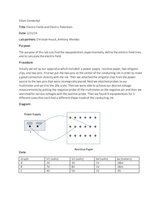
- 1. + - Ethan Vanderbyl Title: ElectricFields and Electric Potentials Date: 2/21/14 Lab partners: Christian Houck, Anthony Mendez Purpose: The purpose of this lab is to find the equipotentials experimentally, define the electric field lines, and to calculate the electric field. Procedure: Initially we set up our apparatus which included: a power supply, resistive paper, two alligator clips, and two pins. First we put the two pins at the center of the conducting ink in order to make a good connection directly with the ink. Then we attached the alligator clips from the power source to the two pins that were strategically placed. Next we attached probes to our multimeter and set it to the 20v scale. Then we were able to achieve our desired voltage measurements by putting the negative probe of the multimeter on the negative pin and then we searched for various voltages with the positive probe. Then we found 9 equipotentials for 3 different cases that each had a different shape made of the conducting ink. Diagram: + + + + + + + + + + + + + + + + + + Data: Graph: V1 (volts) V2 (volts) ∆V (volts) ∆x (meters) A 2V 3V 1V .08m B 7V 8V 1V .06m C 4V 5V 1V .05 Resistive Paper PowerSupply
- 2. Results: Graph: Electric Field (N/C) A: Irregular object near straight line 12.5 N/C B: Circle Between 2 parallel lines 16.7 N/C C: 2 Small Electrodes 20 N/C Calculations: 1. 𝐸 = − ∆𝑉 ∆𝑥 SampleCalculations: 1. 𝐸 = −(1𝑣−2𝑣) .08𝑚 = 12.5𝑁 𝐶 Questions: (None) Conclusion: Over the duration of this lab we successfully mapped the potential by drawing equipotential surfaces. In this lab we proved that field lines are directly related to equipotentials and we also revealed the validity and usefulness of the equation: = − ∆𝑉 ∆𝑥 . We used this equation to identify the electric field by calculating the difference in voltage and distance in two equipotentials. The graphs clearly represent the symmetrical qualities of the equipotential surfaces and they express the fact that the electric field lines are perpendicular to the equipotential surfaces. This lab successfully identifies and proves the purpose of the experiment because both our data and graphs were very accurate to what the intended readings should be. Our graphs express the correct symmetry throughout and our calculated E is very standard because the field strength should be low. Our E field calculations were from 12 to 20 N/C, which infers the validity of all three trials because the variance is very low. Over the course of this lab minor errors were experienced due to various issues such as: inaccurate equipment, discrepancy in measuring ∆x, and inaccurate voltage readings throughout the high resistance-paper. In particular we had a discrepancy issue with our multimeter which may have been caused by a faulty meter, a bad circuit, or a bad connection. In addition we also had issues measuring ∆x because of the limitations of a common ruler and the inaccuracy of the lines of symmetry. Finally we also experienced error while measuring each individual voltage, which was induced by the sensitivity of the multimeter and the fact that the paper was not infinite. This experiment could have been improved by using a more accurate mulitmeter, a better circuit with better connections, freshly applied silver conducting ink, an even larger sheet of resistant paper, a better ruler to measure ∆x, and various other things. The overall procedure could have incurred less error by using better equipment with more consistent readings and a more accurate circuit that introduced 0 resistance. Overall this experiment introduced various errors, but expressed the correct symmetry of the equipotential surfaces.