1. The document describes a KOBA ball bar, which is a portable calibration tool for large coordinate measuring machines (CMMs). It consists of ceramic spheres mounted on carbon fiber or stainless steel distance tubes at regular intervals.
2. To calibrate the ball bar, individual sphere-tube-sphere lengths are measured on a high-precision CMM. This establishes traceability of the ball bar's lengths to national standards.
3. A ball bar calibration certificate provides the measured lengths of combinations of spheres and tubes, ambient measurement conditions, stated measurement uncertainty, and other details ensuring the ball bar's lengths are accurately certified.
Verification of areas of indian standard i sections with multiple unit weightseSAT Journals
Abstract Indian Standard I-Sections consist of some sections of the same designation but of different unit weights. The only major change in geometry indicated in SP:6(1)-1964 in these sections is the web thickness. The areas of such sections have been calculated by applying the corrections to the flange widths, considering the details of manufacturing process of such rolled steel sections given in IS 808 -1989 (Reaffirmed 1989). It is found that the area of only one such I-Section, namely, ISWB600 @ 145.1 kg/m, of this category, is differing from the area given in SP:6(1)-1964. It has also been found that the area of this section perfectly matches with the area given in SP: 6(1)-1964, if the correction to flange width due to the manufacturing process is neglected. Index Terms: SP: 6(1)-1964, IS 808-1989, I – Sections with multiple unit weights, Correction to flange width. Cross Sectional Areas
IJRET : International Journal of Research in Engineering and Technology is an international peer reviewed, online journal published by eSAT Publishing House for the enhancement of research in various disciplines of Engineering and Technology. The aim and scope of the journal is to provide an academic medium and an important reference for the advancement and dissemination of research results that support high-level learning, teaching and research in the fields of Engineering and Technology. We bring together Scientists, Academician, Field Engineers, Scholars and Students of related fields of Engineering and Technology.
The document summarizes an experimental study that evaluated lap splices between headed reinforcing bars and hooked reinforcing bars in reinforced concrete beams. Seven beam specimens with different bar diameters, lap lengths, and confinement were tested. The test results showed that specimens with shorter lap lengths relative to code design equations had maximum loads ranging from 56-94% of nominal strength and failed in bond splitting or prying near the lap splice. Confinement over the lap zone improved stiffness and strength. The study concluded that code design equations need to specify longer lap lengths between headed and hooked bars to ensure the splice reaches nominal strength.
IJERA (International journal of Engineering Research and Applications) is International online, ... peer reviewed journal. For more detail or submit your article, please visit www.ijera.com
A Study of Reduced Beam Section Profiles using Finite Element AnalysisIOSR Journals
Abstract: Reduced beam section (RBS) is one of the several connection types, which is economical and
popular for use in new steel moment frame structures in seismic zone. To form RBS connection, some portion of
the beam flanges at a short distance from column face is purposefully trimmed so that the yielding and plastic
hinge occurs within this area of flanges. Use of RBS connection is found advantageous due to: a) the shear
force in the panel zone is reduced; b) the force demand in column continuity plates i.e. stiffeners are reduced;
and c) strong-column – weak-beam requirement is satisfied. Although, radius cut RBS is qualified by
ANSI/AISC, FEMA codes, various flange cut shapes like constant, tapered, radius cut, drilled holes are possible
to reduce the cross sectional area of beam flanges. The purpose of this study is to understand behavior of RBS
beam-to-column moment connections for various flange cut geometries. This document represents nonlinear
finite element analysis of the connection models performed using the computer program, ANSYS/Multiphysics
Keywords - Steel structures, steel connections, reduced beam section, RBS profiles
1) There are multiple methods for measuring distance in surveying, each with their own advantages and limitations depending on the environment, intended use of the data, and available equipment.
2) Common distance measuring methods include pacing, using an odometer wheel, chaining, stadia, and electronic distance measurement.
3) The most important factor in selecting the best distance measuring method is the intended use of the data being collected. Precision and limitations vary between methods.
This document describes calibration standards produced by KOBA for optical and tactile coordinate measuring instruments. It discusses stepped standards made of corrosion-resistant carbide, sphere standards with scratch-resistant measuring surfaces, and 3D calibration standards made of optically-cooperative ceramic materials that can be measured both optically and tactilely. These standards are used to calibrate instruments like triangulation laser scanners, laser focus measuring systems, fringe projection systems, video measuring systems, multi-sensor measuring instruments, and 3D coordinate measuring machines with optical probes.
The document lists various part numbers and specifications for ruby ball styli. It includes part numbers for styli with ruby balls and carbide shanks, as well as "R type" styli. Diameters, lengths, weights, and other specifications are provided for each part number. Reference spheres, centerline locators, and pins are also mentioned.
The document provides specifications for various ruby ball styli. It lists the order number, ball diameter (dk), shank diameter (ds), length (L), maximum length (ML), and weight (Wt.) for each styli item. It also includes descriptions of the materials used - ruby balls and carbide, stainless steel, ceramic or carbon fiber shanks. Additional information is provided on tungsten carbide, stainless steel, ceramic and carbon fiber materials.
The document lists various part numbers and specifications for ruby ball styli. It includes the following part numbers: M2, M3, M4!, M5, M6, 3/8-24, and Pins. It also references reference spheres, centerline locators, and provides information on ruby and ceramic ball styli, including specifications like ball material, shank material, ferrule material, order number, diameter and length.
The document contains specifications for metric centerline locators and thread positioning inserts including:
- Dimensions for centerline locators in millimeters for various thread sizes
- A metric to English conversion table for reference
- Details for stainless steel thread positioning inserts kits including contents and thread sizes
This document discusses gauge block calibration using a gauge block comparator. It describes the process of mechanical comparison where gauge blocks of similar nominal sizes are compared to determine the length difference using inductive probes. Key factors that influence the measurement include temperature, the gauge block geometry, and the calibration of the standard and comparator equipment. The document provides details on measurement traceability, reference conditions, measurement principles, uncertainty analysis, and strategies for decreasing uncertainty such as improving temperature control and understanding temperature influences.
This document summarizes research using electrochemical impedance spectroscopy (EIS) to evaluate the protective properties of paint coatings on two bridges. EIS measurements were taken in the laboratory and in situ on the bridges. The results showed:
1) EIS provided information about coating properties like resistance, capacitance, and barrier effectiveness.
2) Coatings on external bridge surfaces exhibited high impedance and barrier properties. Coatings on internal surfaces showed signs of water penetration over time.
3) In situ bridge coating measurements correlated well with laboratory coating measurements, indicating EIS can effectively evaluate coatings on structures.
The document discusses an Instron machine, which is a versatile instrument used to measure load from 2 grams to 100 kgs using a strain gauge principle. It consists of a load cell containing metal beams with strain gauges that measure the resistance change when a load is applied. This allows the machine to generate a load-elongation curve on a chart. The Instron machine can test properties of yarns, cords, fibers and other materials under tension, and has applications in measuring tensile, flexural, friction and tear properties. It operates over a wide range of speeds and loads with interchangeable load cells and grips.
This document describes a study comparing the performance of two eddy current sensor coil designs - a rectangular cross-section coil and a tilted cross-section coil - for non-destructive testing of conductive materials. Finite element modeling was used to simulate the magnetic flux density, eddy currents, and impedance changes detected by the coils in the presence of cracks in a test specimen. The simulations showed that the tilted coil design produced stronger magnetic fields near cracks, higher eddy current densities, and larger impedance changes compared to the rectangular coil. This indicates the tilted coil design may provide better sensitivity for crack detection in non-destructive testing applications.
Strain gauges measure deformation or strain in materials and structures caused by applied forces. There are different types of strain including axial, bending, shear, and torsional. Strain gauges work by measuring changes in electrical resistance caused by physical deformation. Common types include semiconductor, thin-film, and bonded resistance strain gauges. Strain gauges are widely used to monitor structures like bridges, buildings, and aircraft to detect deformation and prevent failures or accidents. They provide important safety and monitoring functions across many industries.
Chain surveying involves measuring distances between stations using a chain or tape. Only linear measurements are taken between stations to form a network of triangles. Key aspects include:
- Distances are directly measured between stations using a chain or tape, with no angular measurements
- The area is divided into a network of triangles connected by measured sides
- Instruments include chains, tapes, ranging rods, and cross staffs for laying out right angles
- Sources of error include chain/tape length errors from temperature/tension and mistakes in chaining must be minimized.
This presentation content various types of strain gauges, derivation of gauge factor.
Various course having subject as instrumentation, measuring devices, contenting strain measurement as a topic so introduction to strain gauge can help to understand the topic.
This document discusses advances in metrology, specifically laser metrology and interferometry. It begins by explaining the principles and components of lasers and how they are used for precision measurement. Examples of laser measuring machines described include laser telemetric systems, laser and LED distance measuring instruments, scanning laser gauges, and laser interferometers. Interferometry uses laser beams to perform highly accurate linear and angular measurements. Coordinate measuring machines and digital devices for computer-aided inspection are also summarized.
Slip gauges are rectangular blocks of hardened steel used to measure linear dimensions precisely. They are manufactured to high tolerances through processes like hardening, grinding, and lapping. Different grades have varying accuracies. Accessories like holders and measuring jaws aid slip gauge use. Angles can be measured using a sine bar and slip gauges based on trigonometric relationships between the height of slip gauges and the sine bar's fixed roller distance. Auto-collimators also precisely measure small angles using reflected light.
Modeling and Optimization of Cold Crucible Furnaces for Melting MetalsFluxtrol Inc.
http://fluxtrol.com
Cold Crucible Furnaces (CCFs), widely used in multiple special applications of
melting metals, oxides, glasses and other materials [1], are essentially 3D devices and their modeling is a complicated task. Multiple studies of CCFs have been made for their
optimization, but their electrical efficiency is still low; for metals approximately 25-30% andeven lower. Fluxtrol, Inc., made an extensive study of electromagnetic processes of CCFs using computer simulation and laboratory tests. This study showed that electrical efficiency of CCFs may be strongly improved by means of optimal design of the whole system with use of magnetic flux controllers. Theoretical results had been confirmed by laboratory tests on mockups and by industrial tests with real melting processes. The presentation contains a description of the computer modeling procedure and major findings. They form a basis for optimal design of electromagnetic systems of CCFs.
The document discusses advances in metrology, including laser interferometry and coordinate measuring machines (CMMs). It describes the principles and components of laser interferometry, including laser sources, optical elements, and measurement receivers. Coordinate measuring machines are discussed, including their construction, types of probes, accuracy considerations, and applications for precision inspection. Computer-aided inspection using machine vision systems is also summarized, outlining the key stages of image generation, processing, and analysis.
The document describes a new HVDC field probe developed by ABB to measure electric fields around HVDC equipment. It discusses the probe's design, which uses optical fibers and is less than 20mm in diameter to measure close to surfaces. The document also details calibration of the probe in a plane gap, measurements of fields around a HVDC bushing and cable termination, and findings that an RC model agrees with measurements at short times but deviations occur over longer times likely due to nonlinear conductivity effects. In conclusion, the probe provides robust field measurement data that helps design HVDC equipment and develop more accurate simulation models.
Comparator is an indirect precision instrument that compares the dimensions of a component to a standard rather than providing an actual measurement. It indicates how much the component differs from the standard dimension through magnification. Comparators require little skill to use, eliminate human error, and provide quick, consistent results. Some key types are mechanical, optical, mechanical-optical, electrical, pneumatic, and fluid displacement comparators. Pneumatic comparators use air pressure differences rather than physical contact to measure dimensions and have advantages like high magnification and independence from operator skill.
This document provides details about the design, manufacturing, and testing processes for power transformers. It discusses:
1) The design process, which begins with designing the core and windings based on specifications. Calculations are checked using computer programs.
2) Short circuit strength considerations, including calculating radial and axial forces on windings from leakage flux, and ensuring windings can withstand these forces.
3) Manufacturing of cores from grain-oriented steel, and winding manufacturing steps like paper wrapping conductors and different winding types.
4) Testing includes short circuit testing to prove designs can withstand forces, and ABB has extensively tested transformers.
APE_IM_Article_AppliedOptics_Vol47_No29_Oct10_2008_AsPublishedRainer Wilhelm
This document describes a dual-wavelength low-coherence instantaneous phase-shifting interferometer developed to measure the shape of a segmented mirror with 61 hexagonal segments with subnanometer precision. The interferometer measures the piston (translation along the optical axis) and tip/tilt angles of each segment relative to the central segment. It achieves a piston precision of 0.48 nm rms and a tip/tilt precision of 74 nrad rms. The instrument serves as a reference sensor for controlling the shape of the segmented mirror in closed-loop operation and for evaluating the performance of other phasing cameras being tested.
"Fatigue testing of reinforced concrete beam instrumented with distributed op...TRUSS ITN
The use of fiber optic sensors on civil engineering structural health monitoring (SHM) applications have become quite popular for the past two decades. Within this type of sensors however, the study and use of Optical Backscatter Reflectometry (OBR) based Distributed Optical Fiber Sensors (DOFS) is relatively new. In this way, there is still some uncertainty that would allow the use of this technology in a more systematic and standardized way. Some of this uncertainty is related with the long-term reliability behavior of these sensors when applied on the monitoring of a structure under a large number of load cycles. In this way, the authors conducted a laboratory experiment where a reinforced concrete beam was instrumented with a DOFS that was adhered in a way to allow the measuring of strain on four different longitudinal segments on its bottom surface. A fatigue test was then conducted on this element where the inputted load range was the one expected on a standard highway bridge between its self-weight and the additional traffic load. Furthermore, each longitudinal segment of the DOFS was adhered to the concrete using a different adhesive in order to assess the optimal one in these conditions. The obtained data is then compared with strain gauges that are also instrumented on the concrete beam.
Experimental stress analysis BE notes by mohammed imranMohammed Imran
7th semester, Experimental stress analysis notes as per VTU syllabus by Mohammed Imran, Asst. Prof., Department of Mechanical Engineering, Ghousia College of Engineering-Ramanagaram-562159
Metrology is the science of measurement. It includes theoretical and practical aspects of measurement and ensures accuracy and correctness of measurements. There are various standards used for measurement including line standards, end standards, and wavelength standards. Line standards use scribed lines on a bar to define units of length. End standards define length as the distance between two parallel end faces of blocks or bars. Wavelength standards now define the meter based on the wavelength of light. Slip gauges are commonly used end standards made of steel blocks with precise faces used to build up dimensions. Metrology aims to provide accurate measurements at minimum cost for various applications in manufacturing and quality control.
This document provides recommendations for measuring the dynamic modulus of elasticity of plain concrete specimens in a laboratory. It outlines the test method, which involves applying a variable frequency force to a prismatic concrete sample and measuring its resonant frequency. This frequency is then used in an equation to calculate the dynamic modulus of elasticity. The document specifies the required test apparatus, sample preparation procedures, measurement and calculation methods, and reporting requirements.
This document discusses KOBA-step step gages, which are used to check the accuracy of coordinate measuring machines. KOBA-step gages have multiple gage faces spaced along their body that allow for measuring various dimensions, including outside, inside, and positional lengths. They provide advantages over individual gage blocks by allowing measurements from many points along a single line. The document describes how to use KOBA-step gages to assess a CMM's length measurement uncertainty and check if it meets specifications.
The document lists various styli, ball, and adapter components. It includes ruby and ceramic ball styli with carbide, carbon fiber, or stainless steel shanks. It also lists extensions, adapters, and crossover components made of aluminum 7075 or stainless steel to connect styli of different thread sizes. Reference information is provided on ball grades and materials.
The document lists various reference spheres, pins, and locators available for purchase including:
- Reference spheres types A through D with various ball sizes and specifications
- Pins and reference spheres for locating components
- Centerline locators for positioning workpieces
It also provides ordering information and specifications for the different reference sphere models.
The document contains specifications for ruby ball styli with carbide shanks, including: dimensions for various styli models listed by order number (M2); materials used for balls, shanks and ferrules (M3); and references to tools and solutions for assembling styli configurations (M6).
The document lists various pin styli products including:
- Pin styli with ruby balls and stainless steel or carbide shanks in various sizes identified by diameter (dk), stem diameter (ds), length (L), and weight
- The pin styli can be used with adapters on other pages to allow for modularity and interchangeability
- Additional information is provided on ordering numbers, dimensions, and materials of the pin styli
American Modular Tooling provides modular tooling kits for assembly fixtures. Their kits include clamps, clevises, net blocks, and other components that allow customers to easily assemble customized fixtures. Using these standardized parts is like working with an Erector set, and allows companies to inexpensively build high value fixtures, such as one that holds 21 vehicle panels using only AMT components. AMT also offers storage cabinets to help customers organize their kit components.
Industrial Tech SW: Category Renewal and CreationChristian Dahlen
Every industrial revolution has created a new set of categories and a new set of players.
Multiple new technologies have emerged, but Samsara and C3.ai are only two companies which have gone public so far.
Manufacturing startups constitute the largest pipeline share of unicorns and IPO candidates in the SF Bay Area, and software startups dominate in Germany.
At Techbox Square, in Singapore, we're not just creative web designers and developers, we're the driving force behind your brand identity. Contact us today.
Implicitly or explicitly all competing businesses employ a strategy to select a mix
of marketing resources. Formulating such competitive strategies fundamentally
involves recognizing relationships between elements of the marketing mix (e.g.,
price and product quality), as well as assessing competitive and market conditions
(i.e., industry structure in the language of economics).
B2B payments are rapidly changing. Find out the 5 key questions you need to be asking yourself to be sure you are mastering B2B payments today. Learn more at www.BlueSnap.com.
Discover timeless style with the 2022 Vintage Roman Numerals Men's Ring. Crafted from premium stainless steel, this 6mm wide ring embodies elegance and durability. Perfect as a gift, it seamlessly blends classic Roman numeral detailing with modern sophistication, making it an ideal accessory for any occasion.
https://rb.gy/usj1a2
Unveiling the Dynamic Personalities, Key Dates, and Horoscope Insights: Gemin...my Pandit
Explore the fascinating world of the Gemini Zodiac Sign. Discover the unique personality traits, key dates, and horoscope insights of Gemini individuals. Learn how their sociable, communicative nature and boundless curiosity make them the dynamic explorers of the zodiac. Dive into the duality of the Gemini sign and understand their intellectual and adventurous spirit.
At Techbox Square, in Singapore, we're not just creative web designers and developers, we're the driving force behind your brand identity. Contact us today.
Tata Group Dials Taiwan for Its Chipmaking Ambition in Gujarat’s DholeraAvirahi City Dholera
The Tata Group, a titan of Indian industry, is making waves with its advanced talks with Taiwanese chipmakers Powerchip Semiconductor Manufacturing Corporation (PSMC) and UMC Group. The goal? Establishing a cutting-edge semiconductor fabrication unit (fab) in Dholera, Gujarat. This isn’t just any project; it’s a potential game changer for India’s chipmaking aspirations and a boon for investors seeking promising residential projects in dholera sir.
Visit : https://www.avirahi.com/blog/tata-group-dials-taiwan-for-its-chipmaking-ambition-in-gujarats-dholera/
How MJ Global Leads the Packaging Industry.pdfMJ Global
MJ Global's success in staying ahead of the curve in the packaging industry is a testament to its dedication to innovation, sustainability, and customer-centricity. By embracing technological advancements, leading in eco-friendly solutions, collaborating with industry leaders, and adapting to evolving consumer preferences, MJ Global continues to set new standards in the packaging sector.
Understanding User Needs and Satisfying ThemAggregage
https://www.productmanagementtoday.com/frs/26903918/understanding-user-needs-and-satisfying-them
We know we want to create products which our customers find to be valuable. Whether we label it as customer-centric or product-led depends on how long we've been doing product management. There are three challenges we face when doing this. The obvious challenge is figuring out what our users need; the non-obvious challenges are in creating a shared understanding of those needs and in sensing if what we're doing is meeting those needs.
In this webinar, we won't focus on the research methods for discovering user-needs. We will focus on synthesis of the needs we discover, communication and alignment tools, and how we operationalize addressing those needs.
Industry expert Scott Sehlhorst will:
• Introduce a taxonomy for user goals with real world examples
• Present the Onion Diagram, a tool for contextualizing task-level goals
• Illustrate how customer journey maps capture activity-level and task-level goals
• Demonstrate the best approach to selection and prioritization of user-goals to address
• Highlight the crucial benchmarks, observable changes, in ensuring fulfillment of customer needs
Storytelling is an incredibly valuable tool to share data and information. To get the most impact from stories there are a number of key ingredients. These are based on science and human nature. Using these elements in a story you can deliver information impactfully, ensure action and drive change.
Recruiting in the Digital Age: A Social Media MasterclassLuanWise
In this masterclass, presented at the Global HR Summit on 5th June 2024, Luan Wise explored the essential features of social media platforms that support talent acquisition, including LinkedIn, Facebook, Instagram, X (formerly Twitter) and TikTok.
Anny Serafina Love - Letter of Recommendation by Kellen Harkins, MS.AnnySerafinaLove
This letter, written by Kellen Harkins, Course Director at Full Sail University, commends Anny Love's exemplary performance in the Video Sharing Platforms class. It highlights her dedication, willingness to challenge herself, and exceptional skills in production, editing, and marketing across various video platforms like YouTube, TikTok, and Instagram.
Structural Design Process: Step-by-Step Guide for BuildingsChandresh Chudasama
The structural design process is explained: Follow our step-by-step guide to understand building design intricacies and ensure structural integrity. Learn how to build wonderful buildings with the help of our detailed information. Learn how to create structures with durability and reliability and also gain insights on ways of managing structures.
Structural Design Process: Step-by-Step Guide for Buildings
KOBA Ball Bar
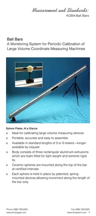
1. Measurement and Standards:
KOBA-Ball Bars
Ball Bars
A Monitoring System for Periodic Calibration of
Large Volume Coordinate Measuring Machines
Sphere Plates, At a Glance
⊕ Ideal for calibrating large volume measuring devices
⊕ Portable, accurate and easy to assemble
⊕ Available in standard lengths of 3 or 5 meters —longer
available by request
⊕ Body consists of three rectangular aluminum extrusions
which are foam filled for light weight and extreme rigid-
ity.
⊕ Ceramic spheres are mounted along the top of the bar
at certified intervals
⊕ Each sphere is held in place by patented, spring-
mounted devices allowing movement along the length of
the bar only.
Phone (586) 759-2400 Fax (586) 759-2423
www.pmargage.com www.shoppwm.com 1
2. Measurement and Standards:
KOBA-Ball Bars
KOBA-
Significant Features of the KOBA-Ball Bar
⊕ Repeatability of measuring lengths by means of a
3-point contact on the joint of the ball-distance tube.
⊕ Carbide contact points provide long-term stability
⊕ Simple calibration
⊕ Short set-up and take-down times
⊕ Easy handling due to light weight and maximum
element lengths of 1800mm
⊕ Variable lengths and divisions
⊕ Constant axial force on the joint of the ball distance tube
⊕ Ceramic balls and special steel distance tubes are
corrosion resistant
⊕ Carbon fiber distance tubes offer coefficient of thermal expansion
close to 0 (zero)
Construction and Handling
The carrying body is a CFC-GFC
aluminum box filled with foam, the
most significant features of which
are high rigidity, good vibration
dampening and low weight. The
number of individual elements de-
pends on the total length. These
elements are securely held together
by fastening elements.
The fixing elements are ceramic
balls connected over spring ele-
ments which have retainers in their bases. The spring element provides
freedom of movement in axial direction which is essential for perfect bond-
ing between the ball and the distance tube. Stress is applied to the rods
and the balls which are lined up by means of a clamping unit with repro-
ducible force in the axial direction and which support themselves upon a
fixed skewback (springer) at the opposite end, thereby avoiding changes
in the length occurring due to varied pre-stress forces.
Phone (586) 759-2400 Fax (586) 759-2423
2 www.pmargage..com www.shoppwm.com
3. Measurement and Standards:
KOBA-Ball Bars
The tube elements are designed to enable self-centering of the skewbacks
and the clamping units. The distance tubes are mode of stainless steel or
CFC and have a carbide 3point contact at the ends for the ceramic balls.
This form of contact ensures the best repeatability of measured lengths.
Why are distance tubes available in two materials?
⊕ Stainless Steel: measuring
results from distance tubes of
stainless steel, with a coefficient of
thermal expansion of 16 x 10-6 K-1,
reflect environmental influences.
This means that fluctuations in
temperature are reproduced in
length deviations and present the
actual uncertainty of measurement.
⊕ Carbon Fiber: distance tubes
of CFC, with a coefficient of thermal
expansion of 0 (zero), do not react
to fluctuations in temperature and
merely show the uncertainty of
measurement of the measuring
instrument with no influence from
environmental conditions.
The KOBA-Ball Bar is mounted by means of a step bearing and a stable,
adjustable height support or two supports can be used for horizontal
mounting.
Because of its well-planned design, a completely dismounted test body
can be set up within 20 minutes, by one person. Changing the position of
the test body within the measuring volume can be made in minutes.
Ball Bar Application and Evaluation
The ball bar is adjusted and measured in various positions within the
measuring volume according to specific requirements. The arrangement
can be carried out in the direction of individual axes, of diagonals in the
measuring planes or of the space diagonals in the measuring volume of
the CMM to be examined. The recorded measuring values can be evalu-
ated in our GUK-KS software, which is independent of the CMM manufac-
turer and can administer up to 100 coordinate measuring machines.
Technical Data:
Attainable Lengths: 2,000mm t0 8,000mm
Divisions 200mm, 300mm, 400mm, 500mm,
(distance between balls): special distance on request
Useable vertical range 250mm to 3,000mm, depending
of height: on length
Probing elements: Ceramic balls, 30mm diameter
Distance tubes: Stainless steel or CFC tubes with carbide
3-point contacts
Weight: Approximately 8kg/m
Length of individual elements: Maximum 1,800mm
Phone (586) 759-2400 Fax (586) 759-2423
www.pmargage.com www.shoppwm.com 3
4. Measurement and Standards:
KOBA-Ball Bars
Ball Bar Calibration
Calibration of individual measuring
lengths can be carried out by the user
on an exact coordinate measuring
machine of normal construction size,
consequently the cost of calibration
is greatly reduced. For the purpose
of calibration, only the first supporting
body element is used. On this ele-
ments a small number of measuring
lengths, corresponding to the size of
the measuring machine, are mounted
using the clamping unit; the respective
pairs (i.e., ball 1 → rod 1 → ball 2 / ball
2 → rod 2 → ball 3, etc.) are meas-
ured and the values of the distances
of center points of balls are noted in a
calibration document.
1. Calibration Object: The calibration object is an artifact (ball bar)
which can be dismantles and is used for the calibration and interim
checking of coordinate measuring machines. The artifact consists of
10 distance tubes and 11 ceramic spheres.
2. Calibration procedure: The ball bar is calibrated using a “calibration
device for linear comparison standards” (DK Nr. 0372). The measur-
ing system of the de-
vice consists of a plane
mirror laser interfer-
ometer with a mobile
probing component
(Zeiss probe system)
and a permanently
mounted plane mirror.
A stabilized, dual-
frequency He-Ne laser
is used whose wave
length is corrected by
the refractive index of
air determined in ac-
cordance with the
Edlen formula
(parameter method).
Traceability to the unit
length “meter” is estab-
lished by calibration of the overall measuring system, using parallel
gage blocks of the nominal size 50mm (official label 0274 PTB 98), of
the nominal size 500mm (official label 111 PTB 96) and of the nominal
size 1,000mm (official label 110 OTB 96).
The respective sphere mid-point distances of the different combina-
tions , e.g. sphere 1 → bar 1 → sphere2, sphere2 → bar 2 → sphere
3, etc. were measured.
3. Ambient Conditions: the temperature, air pressure and humidity
during measurement have been recorded on a data carrier in the
calibration lab and can be communicated if necessary.
Phone (586) 759-2400 Fax (586) 759-2423
4 www.pmargage..com www.shoppwm.com
5. Measurement and Standards:
KOBA-Ball Bars
4. Measurement Results: the calibration results indicate the sphere
mid-point distances of combinations:
The lengths are specified relative to the reference temperature of
20° C and to the metrological condition of the ball during calibration.
A linear thermal expansion coefficient of 11.5—10-6 K1 was used to
reduce the results of 20° C.
5. Measuring Uncertainty: the measuring uncertainty for the sphere
mid-point distance is U=0.4µm + 2 x 10-6=L, L=the length of the bar.
The specification indicates the upgraded measuring uncertainty
Combination Sphere mid-point T1 (°C)
distance (mm)
Sphere 0 → Bar 1-2 → Sphere 1 500.09970 20.05
Sphere 1 Bar 1-2 Sphere 2 200.20707 20.03
Sphere 2 Bar 2-3 Sphere 3 500.26838 20.04
Sphere 3 Bar 3-4 Sphere 4 500.46535 20.04
Sphere 4 Bar 4-5 Sphere 5 500.30931 20.05
Sphere 5 Bar 5-6 Sphere 6 500.39038 20.04
Sphere 6 Bar 6-7 Sphere 7 500.05702 20.03
Sphere 7 Bar 7-8 Sphere 8 500.44678 20.06
Sphere 8 Bar 8-9 Sphere 9 500.00810 20.09
Sphere 9 Bar 9-10 Sphere 10 500.5244 20.08
1. Temperature of ball bar during measurement (uncertainty=0.03k)
resulting from the multiplication of the standard measuring uncer-
tainty by the factor k=2. It was determined in conformity with DKD-3.
The values of the measuring parameter lie within the specified range
with probability of 95%.
Phone (586) 759-2400 Fax (586) 759-2423
www.pmargage.com www.shoppwm.com 5