Mechanical Measurements and Metrology
INTRODUCTION TO
METROLOGY
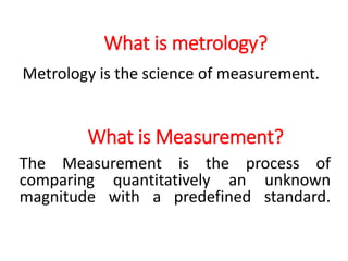
What is metrology?
What is Measurement?
The Measurement is the process of
comparing quantitatively an unknown
magnitude with a predefined standard.
Metrology is the science of measurement.
4
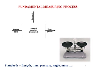
FUNDAMENTAL MEASURING PROCESS
Standards – Length, time, pressure, angle, mass ….
5
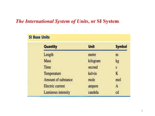
The International System of Units, or SI System.
6
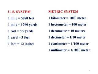
U. S. SYSTEM
1 mile = 5280 feet
1 mile = 1760 yards
1 rod = 5.5 yards
1 yard = 3 feet
1 foot = 12 inches
METRIC SYSTEM
1 kilometer = 1000 meter
1 hectometer = 100 meter
1 decameter = 10 meters
1 decimeter = 1/10 meter
1 centimeter = 1/100 meter
1 millimeter = 1/1000 meter
Metrology (from Ancient Greek metron (measure) and
logos (study of)) is the science of measurement.
Metrology includes all theoretical and practical aspects of
measurement.
A quantity measured is incomplete without units
Measurements play a vital role in every field of R & D
and the present day progress has enhanced its importance.
It is the science of measurements and associated with the
correctness, the evaluation of uncertainty of measurement
and also the validation of the results by specifying its
limitations.
Objectives of Metrology:
The basic objective of metrology is to determine whether a component
has been manufactured to the required specification. The advances in
metrology have made possible the mass production of modern ultra-
precise apparatus. Metrology is an essential past of the development of
technology.
The basic objectives of metrology are as follows:
1. To provide required accuracy at minimum cost
2. Thorough evaluation of newly developed products, to ensure that
components are within the specified dimensions.
3. To reduce the cost of rejections and rework by applying statistical
quality control techniques.
Continued…
4. To reduce the cost of inspections by effective and efficient
utilization of available facilities.
5. To maintain accuracies of measurement through periodical
calibration of the measuring instruments.
6. To prepare designs for gauges and special inspection fixtures.
7. To standardize measuring methods by proper inspection methods
at the development stage itself.
8. To asses the measuring instrument capabilities and ensure that
they are adequate for their specific measurements.
10
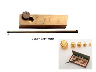
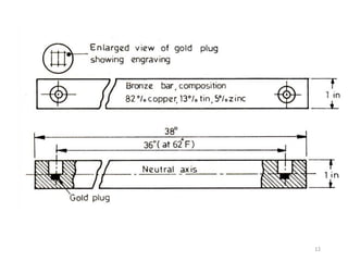
† The imperial standard yard is a bronze bar of one inch
square cross section and 38 inches long.
† A round recess, one inch away from two ends up to central
plane of the bar.
† A gold plug 0.1 inch diameter having three lines engraved
transversely and two lines longitudinally is inserted into these
holes so that the lines are in neutral plane.
† Yard is then defined as the distance between the two central
transverse lines of the plug at 62oF.
† The purpose of keeping the gold plug lines in neutral axis is
due to bending of beam, the neutral axis remains unaffected
IMPERIAL STANDARD YARD
11
1 yard = 0.9144 meter
12
13
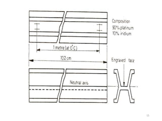
INTERNATIONAL PROTOTYPE METER
† This is the distance between the center portions of the two
lines engraved on the polished surface of a bar of pure
platinum(90%)- iridium (10%) alloy which is non oxidizable
and retain good polished surface.
† The bar is kept at 0oC and under normal atmospheric
pressure
† It is supported by two rollers at least 1cm diameter
symmetrically situated in the same horizontal plane at a
distance of 571mm, so as to give minimum deflection.
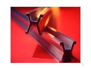
† It has a shape of winged section (tresca cross section) having a
web whose surface lines are on the neutral axis.
† The shape gives the maximum rigidity
14
† The overall width and depth are 16mm each
† This standard is kept in BIPM in Paris (Bureau of
International prototype Meter)
† Thus one yard was equal to 0.91439841m. As
American yard was longer by four parts in one
million, international yard was adopted as 0.9144m
15
16
17
† Because of the problems of variation in length of
material length standards, the possibility of using light
as a basic unit to define primary standard has been
considered.
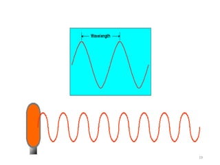
† The wavelength of the selected radiation was measured
and used as the basic unit of length.
† Since wavelength standard is not a physical one, it need
not be preserved.
† Further, it is easily reproducible and the error of
reproduction is in the order of one part in 100 million.
WAVELENGTH STANDARD (1960)
18
Definitions according to wavelength standard
† The Meter is defined as 16,50,763.73 wavelengths of
the orange radiation in vacuum of the krypton-86
isotope.
† The Yard is defined as 15,09,458.35 wavelengths of
the orange radiation in vacuum of the krypton-86
isotope.
† The yard is also defined as 0.9144 meter.
† The substance krypton-86 is used because it produces
sharply defined interference lines and its wavelength
was the most uniform known at that time.
19
20
Advantages of using Wavelength (light) Standard
1. Length does not changes.
2. It can be reproduced easily if destroyed.
3. This primary unit can be accessible to any physical
laboratories.
4. It can be used for making comparative measurements.
5. much higher accuracy compare to material standards.
6. Wavelength standard can be reproduced consistently at any
time and at any place.
21
STANDARDS OF MEASUREMENTS
† There are two standard measurement systems being used
throughout the world, i.e. English and Metric (Yard and
meter).
† Due to advantages of metric system most of the countries
are adopting metric standard with meter as the
fundamental unit of linear measurement.
Length can be measured by
1. Line standard
2. End standard
3. Wavelength standard
22
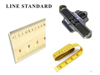
LINE STANDARD
According to this standard yard or meter is
defined as the distance between scribed lines on a
bar of metal under certain conditions of
temperature and support.
23
LINE STANDARD
24
CHARACTERISTICS OF LINE STANDARDS
1. Scales can be accurately engraved.
Example: A steel rule can be read to about ± 0.2 mm of true
dimension.
2. A scale is quick and easy to use over a wide range of
measurements.
3. The scale markings are not subjected to wear although
significant wear on leading ends results in
"UNDERSIZING".
4. Scales are subjected to parallax effect, which is a source of
both positive and negative reading errors.
5. Scales are not convenient for close tolerance length
measurements.
25
END STANDARDS
† When the length being measured is expressed as the
distance between two parallel end faces then it is
called "End-standard".
† End standards can be made to a very high degree of
accuracy.
† They consists of standard blocks or bars used to build
up the required length.
† Examples: Slip gauges, gap gauges, end of micrometer
anvils etc.
26
CHARACTERISTICS OF END STANDARDS
1. End standards are highly accurate and are well suited to
measurements of close tolerances.
2. They are time consuming in use and prove only one dimension
at a time.
3. Dimensional tolerance as small as 0.0005 mm can be obtained.
4. End standards are subjected to wear on their measuring faces.
5. They are not subjected to the parallax effect since their use
depends on "feel".
6. Groups of blocks are "wringing" together to build up any
length, faulty wringing leads to damage.
7. The accuracy of both End and Line standards are affected by
temperature change.
27
SUBDIVISION OF STANDARDS
† The imperial standard yard and international prototype
meter, defined previously are master standards and cannot be
used for ordinary purposes.
† Thus, depending upon the importance of accuracy required,
the standards are sub-divided into four grades.
1. Primary Standards
2. Secondary Standards
3. Tertiary Standards
4. Working standards
28
PRIMARY STANDARDS
† The standard unit of length, Yard or meter does not
change its value and it is strictly followed and precisely
defined that there should be one and only material
standard preserved under most careful condition. This is
called primary standard.
† This has no direct application.
† They are used only at rare intervals of 10 or 20 years
solely for comparison with secondary standards.
29
SECONDARY STANDARDS
† These are close copies of primary standards with respect
to design, material and length.
† These are made, as far as possible exactly similar to
primary standards.
† Any error existing in these standards is recorded by
comparison with primary standards after long intervals.
† They are kept at number of places under great
supervision and are used for comparison with tertiary
standards whenever desired.
† This also acts as safeguard against the loss or destruction
of primary standard.
30
TERTIARY STANDARDS
† The primary or secondary standards exists as the
ultimate controls for reference at rare intervals.
† Tertiary standards are reference standards employed by
National Physical Laboratory (N.P.L) and are the first
standards to be used for reference in laboratories and
workshops.
† They are also made as true copy of secondary standards
and are kept as reference for comparison with working
standards
31
WORKING STANDARDS
† These standards are similar in design to primary,
secondary and tertiary standards, but being less in cost
and are made of low grade materials.
† They are used for general applications in metrology
laboratories.
† Sometimes standards can also be classified as
† Reference standards (used for reference purposes)
† Calibration standards (used for calibration of inspection
and working standards)
† Inspection standards (used by inspectors)
† Working standards (used by operators)
32
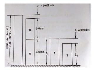
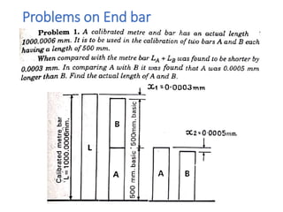
PROBLEM 1
A calibrated meter end bar has an actual length of 1000.0003 mm.
It is to be used in the calibration of two bars A and B, each having
a basic length of 500 mm.
When compared with the meter bar LA + LB was found to be
shorter by 0.0002 mm. In comparing A with B it was found that A
was 0.0004 mm longer than B. Find the actual length of A and B.
33
34
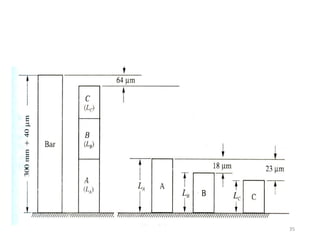
PROBLEM 2
Three 100 mm end bars are measured on a level
comparator by first wringing them together and
comparing with a 300 mm bar. The 300 mm bar has a
known error of + 40 μm and the three bars together
measure 64 μm less than the 300 mm bar. Bar A is 18
μm longer than bar B and 23 μm longer than bar C.
Find the actual length of each bar.
35
36
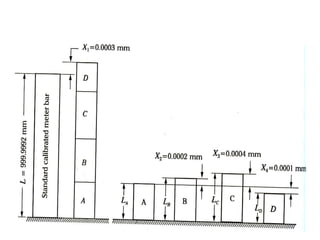
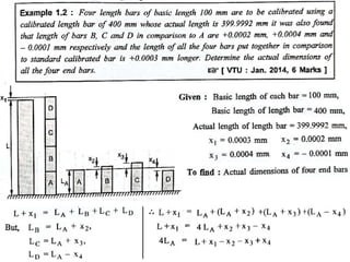
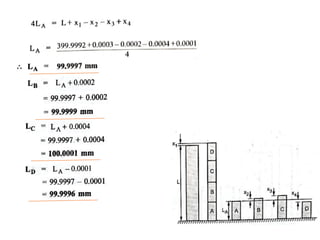
PROBLEM 3
Four length bars A, B, C, D of approximately 250 mm
each are to be calibrated with standard calibrated meter
bar which is actually 0.0008 mm less than a meter. It is
also found that, bar B is 0.0002 mm longer than bar A,
bar C is 0.0004 mm longer than bar A and bar D is
0.0001 mm shorter than bar A. The length of all four
bars put together is 0.0003 mm longer than the
calibrated standard meter. Determine the actual
dimensions of each bar. (VTU Jan 2005)
37
38
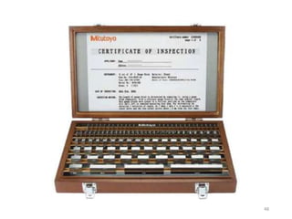
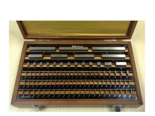
SLIP GAUGES
† Also known as Johannsen Gauges or Gauge Blocks
† They are rectangular blocks of steel having a cross-
section of 30 mm long and 10 mm wide, and are most
commonly used end standards in engineering
practice.
† The size of a slip gauge is defined as the distance
between two plane measuring faces.
† They are made up of high grade steels with a range
of sizes in a set enabling dimensions to build up to
0.005 mm, 0.001 mm or 0.0005 mm according to the
set chosen.
39
† Slip gauges are also manufactured from tungsten
carbide, which is an extremely hard and wear resistant
material.
† The slip gauges are first hardened to resist wear and
carefully stabilized so that they are independent of any
subsequent variation in size or shape.
† After being hardened, blocks are carefully finished on
the measuring faces to such a fine degree of finish,
flatness and accuracy that any two such faces when
perfectly clean may be "wrung" together.
40
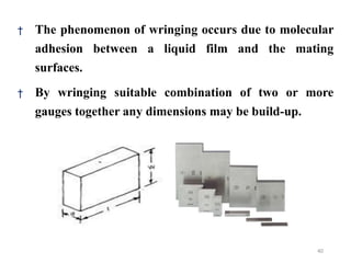
† The phenomenon of wringing occurs due to molecular
adhesion between a liquid film and the mating
surfaces.
† By wringing suitable combination of two or more
gauges together any dimensions may be build-up.
41
WRINGING PHENOMENON
† The term ‘Wringing’ refers to the conditions of intimate
and complete contact and permanent adhesion between
measuring faces which is brought about by wringing
together the surfaces without application of pressure,
assuming that the surfaces have been thoroughly
cleaned and exhibit a good standard of flatness and
smoothness
† The phenomenon of wringing occurs due to molecular
adhesion between a liquid film and the mating surfaces
of the flat surfaces
42
† The precision of the slip gauges depends on the
successful wringing
† The gap between the two pieces is observed to be
0.00635 microns which is negligible
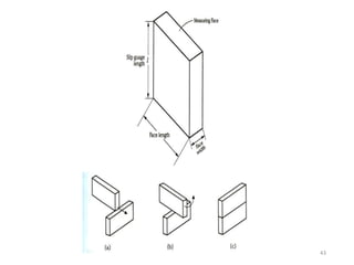
† One gauge is placed perpendicularly on the other gauge
and it is slide first followed by the twisting motion
which fits the gauges together
† The overall thickness of the wrung gauges is equal to
the sum of individual gauges
43
44
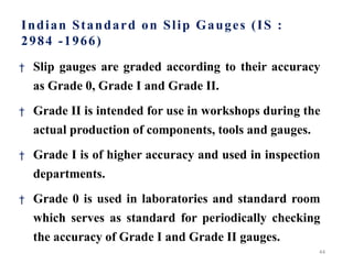
Indian Standard on Slip Gauges (IS :
2984 -1966)
† Slip gauges are graded according to their accuracy
as Grade 0, Grade I and Grade II.
† Grade II is intended for use in workshops during the
actual production of components, tools and gauges.
† Grade I is of higher accuracy and used in inspection
departments.
† Grade 0 is used in laboratories and standard room
which serves as standard for periodically checking
the accuracy of Grade I and Grade II gauges.
45
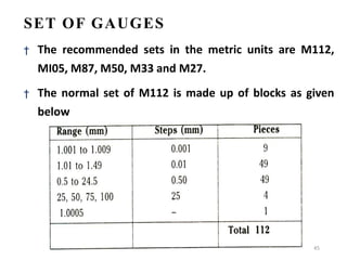
SET OF GAUGES
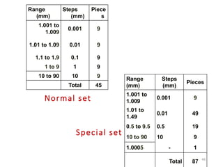
† The recommended sets in the metric units are M112,
MI05, M87, M50, M33 and M27.
† The normal set of M112 is made up of blocks as given
below
46
Range
(mm)
Steps
(mm)
Piece
s
1.001 to
1.009
0.001 9
1.01 to 1.09 0.01 9
1.1 to 1.9 0.1 9
1 to 9 1 9
10 to 90 10 9
Total 45
Range
(mm)
Steps
(mm)
Pieces
1.001 to
1.009
0.001 9
1.01 to
1.49
0.01 49
0.5 to 9.5 0.5 19
10 to 90 10 9
1.0005 - 1
Total 87
Normal set
Special set
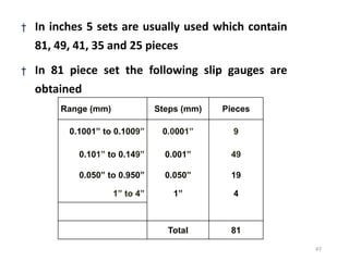
Range (mm) Steps (mm) Pieces
0.1001” to 0.1009” 0.0001” 9
0.101” to 0.149” 0.001” 49
0.050” to 0.950” 0.050” 19
1” to 4” 1” 4
Total 81
47
† In inches 5 sets are usually used which contain
81, 49, 41, 35 and 25 pieces
† In 81 piece set the following slip gauges are
obtained
48
49
50
Numerical Problems on Building of Slip Gauges
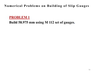
PROBLEM 1
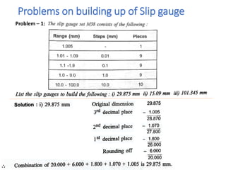
Build 58.975 mm using M 112 set of gauges.
51
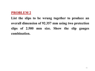
PROBLEM 2
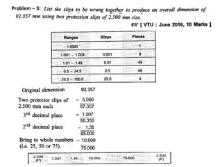
List the slips to be wrung together to produce an
overall dimension of 92.357 mm using two protection
slips of 2.500 mm size. Show the slip gauges
combination.
52
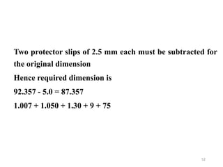
Two protector slips of 2.5 mm each must be subtracted for
the original dimension
Hence required dimension is
92.357 - 5.0 = 87.357
1.007 + 1.050 + 1.30 + 9 + 75
53
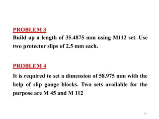
PROBLEM 3
Build up a length of 35.4875 mm using M112 set. Use
two protector slips of 2.5 mm each.
PROBLEM 4
It is required to set a dimension of 58.975 mm with the
help of slip gauge blocks. Two sets available for the
purpose are M 45 and M 112
Angular Measurements
• The angle is defined as the opening between two lines
which meet at a point. If one line is moved around a point
in an arc, a complete circle can be formed and it is from
this circle the units of angle are derived. If a circle is
divided into 360 parts, then each part is called a degree
(O).
• An angle is one which requires no absolute standard, and
it is the precision with which a circle can be divided to get
the correct measure of angle.
• Each degree is further divided into sixty parts called
minutes (') and each minute is further subdivided into 60
parts called seconds (").
• Angular measurement is generally concerned with the measurement of
individual angles on gauges, tools as well as small angular changes and
deflections etc.
• An alternative method of defining angle is based on the relationship
between the radius and arc of a circle.
• This unit is called radian and is defined as the angle subtended by an
arc of a circle of length equal to the radius.
• The following instruments are used to measure the angles of the parts:
1. Bevel protractor
2. Sine bar
3. Sine center
4. Angle gauges
5. Clinometers
Angle Gauges
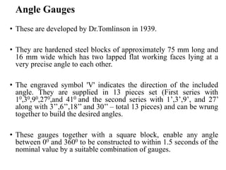
• These are developed by Dr.Tomlinson in 1939.
• They are hardened steel blocks of approximately 75 mm long and
16 mm wide which has two lapped flat working faces lying at a
very precise angle to each other.
• The engraved symbol 'V' indicates the direction of the included
angle. They are supplied in 13 pieces set (First series with
10,30,90,270,and 410 and the second series with 1’,3’,9’, and 27’
along with 3’’,6’’,18’’ and 30’’ – total 13 pieces) and can be wrung
together to build the desired angles.
• These gauges together with a square block, enable any angle
between 00 and 3600 to be constructed to within 1.5 seconds of the
nominal value by a suitable combination of gauges.
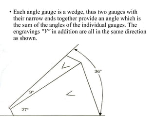
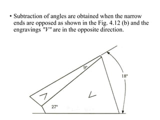
• Each angle gauge is a wedge, thus two gauges with
their narrow ends together provide an angle which is
the sum of the angles of the individual gauges. The
engravings "V" in addition are all in the same direction
as shown.
• Subtraction of angles are obtained when the narrow
ends are opposed as shown in the Fig. 4.12 (b) and the
engravings "V" are in the opposite direction.
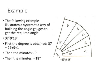
Example
• The following example
illustrates a systematic way of
building the angle gauges to
get the required angle.
• 3709’18’’
• First the degree is obtained: 37
= 27+9+1
• Then the minutes:- 9’
• Then the minutes :- 18’’
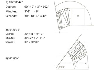
2) 102° 8' 42"
Degree: 90° + 9° + 3° = 102°
Minutes: 9’-1’ = 8’
Seconds: 30’’+18’’-6’’ = 42’’
3) 35° 32' 36"
Degree: 35° = 41 ° - 9° + 3°
Minutes: 32' = 27' + 9' - 3' - l'
Seconds: 36’’ = 30’’+6’’
4) 57° 38’ 9’’
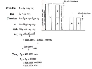
Problems on End bar
= 1000.0006 – 0.0003 – 0.0005
2
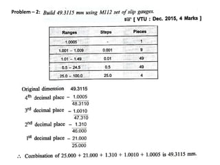
Problems on building up of Slip gauge
Problem – 1:
Problem – 2:
Problem – 3:
Sine Bar
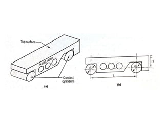
• Sine bars are made from high carbon, high chromium,
corrosion resistant steels which can be hardened, ground and
stabilized.
• Two cylinders of equal diameter are attached at the ends.
• The axes of these two cylinders are mutually parallel to each
other and also parallel to and at equal distance from the
upper surface of the sine bar.
• The distance between the axes of the two cylinders will be
100, 200 & 300 mm in metric system.
• Depending on the accuracy of the centre distance, sine bars
are graded as A grade (accurate up to 0.01 mm/m of length)
and B grade (accurate up to 0.02 mm/m)
Principle of Sine-bar
• The sine bar is designed basically for the precise setting out of
angles and is generally used in conjunction with slip gauges and
surface plate. The principle of operation of the sine bar relies upon
the application of trigonometry.
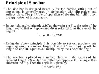
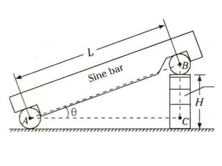
• In the right angled triangle ABC as shown in the Fig, the ratio of the
length BC to that of hypotenuse AB is referred to as the sine of the
angle θ.
i.e. sin θ = BC/AB
• Using the above principle it is possible to set out precisely any
angle by using a standard length of side AB and marking off the
length of side BC equal to AB multiplied by the sine of the angle.
• The sine bar is placed on a surface plate with slip gauges of the
required height (H) under one roller and opposite to the angle θ as
shown in the Fig. Then the angle θ is given by
θ = Sin-l (H/L)
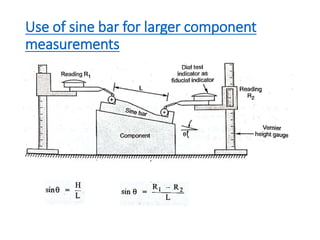
Use of sine bar for larger component
measurements
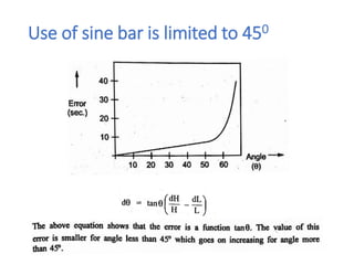
Use of sine bar is limited to 450
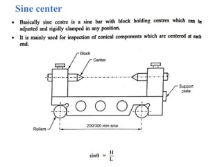
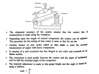
Sine center
Auto-collimator
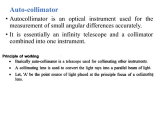
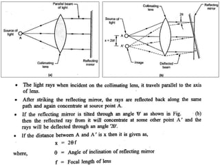
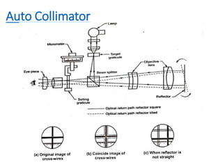
• Autocollimator is an optical instrument used for the
measurement of small angular differences accurately.
• It is essentially an infinity telescope and a collimator
combined into one instrument.
Auto Collimator