SWITCHING SECURITY
ISG Series
ISG2000
ISG1000
SSGSeries
SSG550M
SSG520M
SSG350M
SSG320M
SSG140
QFX Series
QFX10000
QFX5200
QFX5110
QFX5100
QFX3600
QFX3500
QFabric
(QFX3000-G/M)
EX Series
EX9200
EX4600
EX4550
EX4300
EX4200
EX3400
EX3300
EX2300
EX2200
EX2300-C
EX2200-C
SRX Series
SRX5800
SRX5600
SRX5400
SRX4200
SRX4100
SRX3600
SRX3400
SRX1400
SRX1500
SRX550
SRX345
SRX340
SRX320
SRX300
vSRX
ROUTING
PTX Series
PTX5000
PTX3000
PTX1000
ACX Series
ACX5000
ACX4000
ACX2100
ACX2000
ACX1100
ACX1000
ACX500
MX Series
MX2020
MX2010
MX960
MX480
MX240
MX104
MX80
MX40
MX10
MX5
vMX
NetScreen Series
NetScreen-5200
NetScreen-5400
プロダクト・ポートフォリオ(カテゴリ別)
Network Director
Security Director
11.
Datacenter Fabric Switch
QFXseries
Datacenter Service Gateway
SRX series
Universal Edge Router
MX series
JUNOS: THE POWER OF ONE
Integrated Architecture
12.
Campus Ethernet Switch
EXseries
Branch Service Gateway
SRX series
JUNOS: THE POWER OF ONE
Integrated Architecture
JUNOS: THE POWEROF ONE
EX4300 Series
EX3400 Series
EX2300 Series
EX4600
MX Series
PTX Series
SRX3000 Series
SRX5000 Series
SRX320
SRX550
SRX300
SRX340
SRX1400
QFX5100 Series
QFX10000 Series
One OS
branch core
One Release Track
Frequent Releases
14.1 14.2 15.1
One Architecture
–API–
Module
x
vSRX
Operationalモード
• Operationalモードではステータスの確認やシステム操作などに
用いるコマンドを提供しています。
clear Clearinformation in the system
configure Manipulate software configuration information
file Perform file operations
help Provide help information
monitor Show real-time debugging information
mtrace Trace multicast path from source to receiver
op Invoke an operation script
ping Ping remote target
quit Exit the management session
request Make system-level requests
restart Restart software process
set Set CLI properties, date/time, craft interface message
show Show system information
ssh Start secure shell on another host
start Start shell
telnet Telnet to another host
test Perform diagnostic debugging
traceroute Trace route to remote host
43.
Operationalモード
• コマンドは階層構造になっています
• 例:経路情報(簡易版)を確認
root> show route terse
inet.0: 3 destinations, 3 routes (3 active, 0 holddown, 0 hidden)
+ = Active Route, - = Last Active, * = Both
A V Destination P Prf Metric 1 Metric 2 Next hop AS path
* 0.0.0.0/0 S 5 >172.27.112.1
* 172.27.112.0/22 D 0 >ge-0/0/0.0
* 172.27.113.19/32 L 0 Local
clear configure monitor set show
brief exact protocol table terse
bgp chassis interfaces isis ospf route version
大項目
小項目
確認コマンド
経路情報
簡易版
44.
Configurationモード
• Operationalモードにてconfigureと投入することでConfigurationモード
へ移行します
root@lab> configure
Enteringconfiguration mode
[edit]
root@lab#
root@lab> configure
Entering configuration mode
Current configuration users:
fbrooks terminal d0 on since 1999-10-14 07:11:29 UTC,
idle 00:00:49 [edit protocols ospf]
The configuration has been changed but not committed
[edit]
root@lab#
• 他のユーザがconfigurationモードに入っていれば、以下の様に表示されます
45.
Configurationモード:オプション
mike@jnpr1> configure private
warning:uncommitted changes will be discarded on exit
Entering configuration mode
Active
Config
Candidate 1
Candidate 2
user 1
user 2
• configure private コマンドを使用すると、ログインユーザー専用のcandidate
configurationが用意される
• configure exclusive コマンドを使用すると、ログインユーザーが設定変更を
行っている最中に他のログインユーザーが設定変更を行うことを禁止すること
が可能
mike@jnpr1> configure exclusive
warning: uncommitted changes will be discarded on exit
Entering configuration mode user 1
user 2
X
Candidate
Commit 不可
Active
Config
show コマンド
• showコマンド:システム、ステータスに関する情報を表示します
> show arp :ARPテーブルを確認する
> show chassis environment :温度、ファンなどの環境状態を確認する
> show chassis hardware :ハードウェア情報(シリアルナンバー等)を確認する
> show chassis routing-engine :ルーティングエンジン(CPUやMemory)の状態を確認する
> show configuration :稼働中の設定を確認する
> show interfaces :Interfaceの状態を確認する
> show route :経路情報を確認する
> show system uptime :稼働時間を確認する
> show system users :ユーザのログイン状況を確認する
> show system alarms :システムアラームの有無を確認する
> show version :JUNOSソフトウェアバージョンを確認する
show コマンド: オプション
>show interfaces ge-0/0/0 extensive
> show interfaces ge-0/0/0 extensive
Physical interface: ge-0/0/0, Enabled, Physical link is Up
Interface index: 139, SNMP ifIndex: 504, Generation: 142
Link-level type: Ethernet, MTU: 1514, Speed: Auto, Duplex: Auto, BPDU Error: None, MAC-
REWRITE Error: None, Loopback: Disabled, Source filtering: Disabled, Flow control: Enabled,
Auto-negotiation: Enabled,
Remote fault: Online, Media type: Copper, IEEE 802.3az Energy Efficient Ethernet:
Disabled
Device flags : Present Running
Interface flags: SNMP-Traps Internal: 0x4000
Link flags : None
CoS queues : 8 supported, 8 maximum usable queues
Hold-times : Up 0 ms, Down 0 ms
Current address: 5c:5e:ab:7e:75:c3, Hardware address: 5c:5e:ab:7e:75:c3
Last flapped : 2016-02-16 18:44:29 JST (8w1d 17:40 ago)
Statistics last cleared: Never
Traffic statistics:
Input bytes : 995586 0 bps
Output bytes : 1473366 0 bps
Input packets: 10870 0 pps
Output packets: 15732 0 pps
IPv6 transit statistics:
Input bytes : 0
Output bytes : 0
Input packets: 0
Output packets: 0
Input errors:
Errors: 0, Drops: 0, Framing errors: 0, Runts: 0, Policed discards: 0, L3 incompletes:
0, L2 channel errors: 0, L2 mismatch timeouts: 0, FIFO errors: 0, Resource errors: 0
Output errors:
Carrier transitions: 3, Errors: 0, Drops: 0, Collisions: 0, Aged packets: 0, FIFO
errors: 0, HS link CRC errors: 0, MTU errors: 0, Resource errors: 0
Egress queues: 8 supported, 4 in use
Queue counters: Queued packets Transmitted packets Dropped packets
0 best-effort 0 9262 0
1 assured-forw 0 0 0
5 expedited-fo 0 0 0
7 network-cont 0 6470 0
Queue number: Mapped forwarding classes
0 best-effort
1 assured-forwarding
5 expedited-forwarding
7 network-control
Active alarms : None
Active defects : None
MAC statistics: Receive Transmit
Total octets 995586 1473366
Total packets 10870 15732
Unicast packets 8989 9262
Broadcast packets 1876 1872
Multicast packets 5 4598
CRC/Align errors 0 0
FIFO errors 0 0
MAC control frames 0 0
MAC pause frames 0 0
Oversized frames 0
Jabber frames 0
Fragment frames 0
Code violations 0
Autonegotiation information:
Negotiation status: Complete
Link partner:
Link mode: Full-duplex, Flow control: Symmetric, Remote fault: OK,
Link partner Speed: 1000 Mbps
Local resolution:
Flow control: Symmetric, Remote fault: Link OK
Packet Forwarding Engine configuration:
Destination slot: 0 (0x00)
CoS information:
Direction : Output
CoS transmit queue Bandwidth Buffer Priority
Limit
% bps % usec
0 best-effort 95 950000000 95 NA low
none
7 network-control 5 50000000 5 NA low
none
Interface transmit statistics: Disabled
53.
コンソール画面出力に関する操作
• 画面に ---(more)---promptが表示されているときは
以下のキーで操作します
Space: 次画面に進む
b: 前画面に戻る
d: ½画面進む
Enter: 1行進む
/string: 検索
n: 再検索
q: プロンプトに戻る(出力のAbort)
h: これらキーヘルプの表示
> show configuration
## Last commit: 2016-04-12 17:41:17 JST by lab
version 12.3X48-D20.4;
groups {
Japan_ENT_POC {
system {
host-name mino_srx240;
backup-router 172.27.112.1;
time-zone Asia/Tokyo;
dump-on-panic;
root-authentication {
encrypted-password
"$1$YrXW4H1t$0Ry0FagjB/wMKbVM1izGf/"; ## SECRET-DATA
}
name-server {
208.67.222.222;
208.67.220.220;
}
login {
user lab {
uid 2000;
class super-user;
authentication {
---(more)---
54.
コンソール画面出力に関する操作 | no-more
•通常、出力はCLIのスクリーンサイズを考慮して行われます。出力内容が多い場合、CLI画面
に---(more)---を表示し、出力を一時停止します。ログ取得時などは“ | no-more” オプ
ションを使用し、全て一度に表示することが可能です
[edit]
root@lab> show configuration | no-more
## Last commit: 2016-01-25 11:25:54 JST by root
version 10.4R7.5;
groups {
Japan_team {
system {
backup-router 172.16.1.1;
time-zone Asia/Tokyo;
dump-on-panic;
root-authentication {
encrypted-password "$1$YrXW4H1t$0Ry0FagjB/wMKbVM1izGf/";
## SECRET-DATA
}
login {
user lab {
uid 2000;
"$1$4TDfGIs7$.wTBpcNviWRCebbvcSLzv."; ## SECRET-DATA
:
55.
パイプ “|” オプションの利用
•Unix同様のパイプ ”|” をサポート。configやshowコマンド等で有効利用
• root@lab> show configuration | display set
• root@lab> show log messages | no-more
• root@lab> show route | find 192.168.1.0
• root@lab# show interface | save interface_config.txt
root@lab> show configuration | ?
Possible completions:
compare Compare configuration changes with prior version
count Count occurrences
display Show additional kinds of information
except Show only text that does not match a pattern
find Search for first occurrence of pattern
hold Hold text without exiting the --More-- prompt
last Display end of output only
match Show only text that matches a pattern
no-more Don't paginate output
request Make system-level requests
resolve Resolve IP addresses
save Save output text to file
trim Trim specified number of columns from start of line
56.
• Configurationの表示方法を変更する
• 階層表記に加え、行単位での表示も可能
root@EX2200C>show configuration protocols dot1x
traceoptions {
file 1x;
flag all;
}
authenticator {
authentication-profile-name dot-1x;
interface {
ge-0/0/0.0 {
supplicant single-secure;
reauthentication 3600;
}
ge-0/0/3.0 {
supplicant single-secure;
root@EX2200C> show configuration protocols dot1x |display set
set protocols dot1x traceoptions file 1x
set protocols dot1x traceoptions flag all
set protocols dot1x authenticator authentication-profile-name
dot-1x
set protocols dot1x authenticator interface ge-0/0/0.0
supplicant single-secure
set protocols dot1x authenticator interface ge-0/0/0.0
reauthentication 3600
set protocols dot1x authenticator interface ge-0/0/3.0
supplicant single-secure
set protocols dot1x authenticator interface
状況に応じ、お好みの表記方法を選択可能
パイプ “|” 使用例
57.
パイプ “|” 使用例
•Configurationの一部を保存する
• 稼働中のconfigurationの方法
Operationalモードにてshow configuration | save <出力先+ファイル名>
• 編集中のconfigurationの出力方法
Configurationモードにてsave <出力先+ファイル名>
> show configuration | save ftp://abc@172.xx.xxx.xx/Ex_config
Password for abc@172.xx.xxx.xx:
ftp://abc@172.xx.xxx.xx/mx_config 100% of 7928 B 30 MBps
Wrote 352 lines of output to 'ftp://abc@172.xx.xxx.xx/Ex_config'
# save /config/EDITING-CONFIG
Wrote 232 lines of configuration to '/config/EDITING-CONFIG'
※保存先を指定しない場合、userのhome directoryに出力されます
FTPサーバへ出力
/config/へ出力
編集中の設定確認(show | compare)
•show | compare コマンド:編集中の設定と稼動中の設定を比較します
• 過去のconfigと編集中の設定を比較することも可能
user@lab# set interfaces ge-0/0/0 unit 0 family inet address 192.168.1.1/24
user@lab# show | compare
[edit interfaces]
+ ge-0/0/0 {
+ unit 0 {
+ family inet {
+ address 192.168.1.1/24;
+ }
+ }
+ }
Active
Configuration
(rollback 0)
Candidate
Configuration
# show | compare
user@lab# show | compare rollback [1-49]
Active configと比較して、ge-0/0/0にIPアドレスが追加されている
+:追加
ー:削除
73.
設定ファイルの復旧(rollback)
• rollback コマンド:設定ファイルの復旧を行います
•変更した設定ファイルを破棄したい場合は、Rollbackコマンドを投入します。(rollbackはrollback 0の略)
• rollback n(0-49)でファイル番号を指定すると、過去の設定をCandidate Configにコピーすることが可能
で、容易に過去の状態に戻すことが可能です。(過去50世代分の設定ファイルを自動保存)
user@lab# rollback
user@lab# rollback ?
Possible completions: <[Enter]> Execute this command
0 2016-07-14 08:41:21 JST by root via cli
1 2016-07-13 16:01:54 JST by root via cli
2 2016-07-13 15:59:51 JST by root via cli
3 2016-07-13 15:57:33 JST by root via cli
4 2016-07-13 15:57:20 JST by root via cli commit confirmed, rollback in 2mins
5 2016-07-12 15:21:37 JST by lab via netconf
6 2016-07-08 16:35:39 JST by lab via cli
7 2016-06-22 19:30:53 JST by lab via cli
8 2016-06-22 19:28:39 JST by lab via cli
9 2016-06-22 19:28:18 JST by lab via cli
…(snip)
74.
commit オプション(commit confirmed/ at)
• commit confirmed コマンド:一時的に設定を反映します
• 変更を確定する場合は、時間内にcommitを実行します
• デフォルトでは10分(指定可能)
• 時間までにcommitされなければ、自動的にcommit前の状態に戻る
• commit at コマンド:日時を指定してcommitの実行を予約します
• hh:mm:[ss] または “yyyy-mm-dd hh:mm:[ss]”
user@lab# commit confirmed 5
configuration check succeeds
commit confirmed will be automatically rolled back in 5 minutes unless confirmed
commit complete
# commit confirmed will be rolled back in 5 minutes
user@lab# commit at "2016-04-20 00:00"
configuration check succeeds
commit at will be executed at 2016-04-20 00:00:00 JST
Exiting configuration mode
※予約をキャンセルしたいときは、Operationalモードからclear system commit コマンドを実行
75.
Configurationのロード(load)
• load コマンド:configurationファイルをロードします
•loadコマンドはいくつかのオプションがあります
• load factory-default 工場出荷時のconfigをロード
• load override <filename> ロードしたconfigによる置き換え
• load merge <filename> ロードしたconfigを追加
• configファイルは外部のFTPサーバや機器内ディレクトリからロードすることも可能
user@lab# load ?
Possible completions:
factory-default Override existing configuration with factory default
merge Merge contents with existing configuration
override Override existing configuration
patch Load patch file into configuration
replace Replace configuration data
set Execute set of commands on existing configuration
update Update existing configuration
user@lab# load merge /var/tmp/saved_config.txt
user@lab# load merge ftp://user:passwd@192.168.1.1/saved_config.txt
76.
user@lab# load setterminal
[Type ^D at a new line to end input]
set services security-intelligence profile feeds-cc-p1 category CC
set services security-intelligence profile feeds-cc-p1 default-rule then action permit
set services security-intelligence profile feeds-cc-p1 default-rule then log
set services security-intelligence profile Inf-hosts category Infected-Hosts
set services security-intelligence profile Inf-hosts default-rule then action permit
set services security-intelligence profile Inf-hosts default-rule then log
set services security-intelligence policy pol-cc CC feeds-cc-p1
set services security-intelligence policy pol-cc Infected-Hosts Inf-hosts
set services advanced-anti-malware policy skyatp_test match application HTTP
set services advanced-anti-malware policy skyatp_test match verdict-threshold 3
set services advanced-anti-malware policy skyatp_test then action permit
set services advanced-anti-malware policy skyatp_test then notification log
set services advanced-anti-malware policy skyatp_test inspection-profile test
set services advanced-anti-malware policy skyatp_test fallback-options action permit
set services advanced-anti-malware policy skyatp_test fallback-options notification log
set services advanced-anti-malware policy skyatp_test whitelist-notification log
set services advanced-anti-malware policy skyatp_test blacklist-notification log
load complete
Configurationのロード(load set terminal)
• load set terminal コマンド:CLIで追加のsetコンフィグを貼り付けるときに使用
• setコマンドの大量コピー&ペースト時にconfigのとりこぼしが防げます
CTRL+D
貼り付けたいconfigを
terminal上でペースト
し、最後に改行してか
らCTRL+Dを押して読
み込む
キャンセルしたい場合
はCTRL+Cで抜ける
77.
[edit]
user@lab# load mergeterminal
[Type ^D at a new line to end input]
protocols {
ospf {
export static-route;
area 0.0.0.0 {
interface ge-0/0/0.0;
interface ge-0/0/1.0;
interface ge-0/0/2.0;
interface lo0.0 {
passive;
}
}
}
}
policy-options {
policy-statement static-route {
from {
protocol static;
route-filter 10.1.1.0/24 longer;
}
then accept;
}
}
load complete
• load merge terminal コマンド:CLIで追加のconfigを貼り付けるときに使用
• 大量のコピー&ペースト時にもconfigのとりこぼしが防げます、最上位の階層から追加の
configを投入する階層までのパスが全部必要です
• relative オプションを付けると今いる階層に応じてconfigの階層もショートカットされます
Configurationのロード(load merge terminal)
interfaces, protocolsや
policy-optionsなど最上位
の構文から記述していく
[edit protocols ospf]
lab# load merge terminal relative
[Type ^D at a new line to end input]
area 0.0.0.0 {
interface xe-1/0/0.0;
}
area 0.0.0.1 {
stub default-metric 10 no-summaries;
area-range 192.168.16.0/20;
interface ge-0/0/3.0;
}
area 0.0.0.2 {
nssa {
default-lsa {
default-metric 20;
metric-type 1;
type-7;
}
no-summaries;
area-range 172.16.12.0/22;
}
area-range 192.168.48.0/20;
}
load complete
CTRL+D
protocols ospfの階層
に移動しareaのconfig
だけ追加
protocols { ospf { の
記述は不要
CTRL+D
システム設定
• ユーザ設定
• rootユーザのパスワードを設定
•rootユーザ以外のユーザアカウントを作成
• デフォルトでは3つのユーザクラスを選択可能
• read-only :view(show コマンドなど)
• operator :clear, network, reset, trace, view(デーモンの停止, ping/telnet, etc)
• super-user:all(すべて)
root# set system root-authentication plain-text-password
New password:
Retype new password:
root# set system login user TEST class super-user authentication plain-text-password
New password:
Retype new password:
85.
システム設定
• ホスト名の設定
• 時刻設定
•Time zoneを指定する
• NTPサーバを指定する
• DNS設定
root# set system host-name LAB
root# set system time-zone Asia/Tokyo
root# set system name-server 192.168.1.100
root# set system ntp server 10.10.10.100
86.
システム設定
• デバイスのサービス設定
• telnet,sshによるアクセスを有効にする
• FTP, netconfのサービスを有効にする
root# set system services ftp
root# set system services netconf ssh
root# set system services telnet
root# set system services ssh
root# set system services ssh root-login allow RootユーザとしてSSHでログインしたい場合に設定
87.
システム設定
• 管理インタフェース設定
• 例1:EXの管理インタフェース(me0)を設定
•例2:MX, SRXの管理インタフェース(fxp0)を設定
root# set interfaces me0 unit 0 family inet address 192.168.1.1/24
root# set interfaces fxp0 unit 0 family inet address 192.168.1.1/24
me0
EX3400 rear view SRX340 front view
fxp0
※管理ポートは、
MX/SRXは”fxp0”、EXは”me0”、QFXは”em0”、 EX/QFXのVCでは”vme(virtual me)”と命名されています。
Branch SRXのLow End(SRX300/320)など、Out of Bandの管理ポートが存在しないモデルもあります。
88.
システム設定
• ログの設定
• syslogサーバ、ファシリティ、ログレベルを指定
•例:すべてのレベルのログを10.10.10.1へ送信する
■Syslogレベルについて
高 emergency: ソフトウェアコンポーネントの機能停止を招く状況のメッセージ
alert: データベースなどのデータ破損など、直ちに修復が必要な状況のメッセージ
critical: 物理的なエラーなど重大な問題がある状況のメッセージ
error: 上記よりも深刻度の低いエラー状況のメッセージ
warning: モニタリングの必要性がある状況のメッセージ
notice: エラーではないが、特別な処理が必要となる可能性がある状況のメッセージ
info: 対象のイベントまたは非エラー状況のメッセージ
低 any: すべてのレベルのメッセージ
root# set system syslog host 10.10.10.1 any any
89.
システム設定
• SNMP設定
• SNMPコミュニティを作成する
•例:コミュニティ名をpublicに設定、読み込みのみ許可
• SNMPトラップを設定する
• 例:トラップの送信元をLoopback 0に、宛先を10.10.10.1に設定
root# set snmp community public authorization read-only
root# set snmp trap-options source-address lo0
root# set snmp trap-group <group-name> targets 10.10.10.1
物理/論理インタフェース設定例
ge-0/0/0 {
description TEST;
speed1g;
mtu 1400;
ether-options {
no-auto-negotiation;
link-mode full-duplex;
}
unit 0 {
description TEST2;
family inet {
address 10.10.10.1/24;
}
}
unit 100 {
description TEST3;
family inet6 {
address 1::1/64;
}
}
}
物理プロパティ
論理プロパティ
95.
Unit ナンバーとは
• ロジカルプロパティを設定する際には”unit”とよばれる単位で設定します
•一般的なネットワークOSであるサブインタフェースに相当するもの
• unit 0がメインインタフェースに相当
• 1つの物理インタフェースに複数作成することも可能
• インタフェースを動作させるために最低1つは必須
• 物理インタフェースge-0/0/0 の unit 0 は、”ge-0/0/0.0”と表記
• showコマンド等でunitナンバーを指定しない場合はunit 0として認識されます
ge-0/0/0
unit 0
family inet
ge-0/0/0
unit 0
family
ethernet-
switching
Data
L3設定
L2設定
IP
Data ETHIP
ETH
ge-0/0/0 {
unit 0 {
family inet {
address 192.168.1.1/24;
}
}
}
ge-0/0/0 {
unit 0 {
family ethernet-switching {
interface-mode access;
}
}
}
96.
複数unitの設定例
• 1つの物理インタフェースに複数のunitを使用するケース
• unitごとにvlan-idを設定して振り分け
•IPアドレスやFirewall Filterもunitごとに個別に設定可能
ge-0/0/0Packet
unit 10
vlan-id 10
unit 20
vlan-id 20
unit 30
vlan-id 30
ge-0/0/0 {
vlan-tagging;
unit 10 {
vlan-id 10;
family inet {
address 192.168.1.1/24;
}
}
unit 20 {
vlan-id 20;
family inet {
address 172.16.1.1/24;
}
}
unit 30 {
vlan-id 30;
family inet {
address 10.1.1.1/24;
}
}
}
Vlan 10
Vlan 20
Vlan 30Packet
Packet
97.
L3インタフェースの作り方
• EX/QFX/SRXでは、L3の設定を二通りの方法で行うことができます
• インタフェースに直接L3の設定を行う
(RoutedPort)
• ルーター寄りの設定
• “no switchport” のようなもの
• 1つのセグメントには1つのポートのみ
• VLANを受け、複数のセグメントを収容
したい場合はunitを複数作成する
(次ページ)
• VLANを作成し、VLANにL3の設定を
行った上で、インターフェイスとVLAN
を紐付ける (Switch Port)
• スイッチ寄りの設定
• 1つのセグメントに複数のポートが所属できる
• 1つのポートで複数のVLANを使いたい場合、
trunkに設定し、所属するVLANを増やす
set interfaces ge-0/0/0 unit 0 family inet address 192.168.1.1/24
set vlans v10 vlan-id 10
set vlans v10 l3-interface irb.10
set interfaces irb unit 10 family inet address 192.168.10.1/24
set interfaces ge-0/0/0 unit 0 family ethernet-switching vlan members v10
set interfaces ge-0/0/1 unit 0 family ethernet-switching vlan members v10
Routed Port
Switch Port
ge-0/0/0 ge-0/0/X
VLAN 10
ge-0/0/0
ge-0/0/1
VLAN xx
ge-0/0/x
ge-0/0/y
unit 0
family inet
192.168.1.1
unit 0
family inet
192.168.x.x
irb.10
192.168.10.1
irb.x
192.168.x.x
98.
管理者側から強制的にインタフェースを落とす方法
• Disableコマンドを使用してインタフェースを落とす
root# setinterfaces ge-0/0/2 disable
[edit]
root# commit
commit complete
Admin(オペレーター)モードの操作の確認
root# show interfaces
ge-0/0/2 {
disable;
unit 0 {
family inet {
address 140.0.0.12/24;
• Disableコマンドを消去してインタフェースをあげる
root# delete interfaces ge-0/0/2 disable
[edit]
root# commit
commit complete
root# run show interfaces terse
Interface Admin Link Proto Local
Remote
ge-0/0/0 up up
ge-0/0/1 up down
ge-0/0/2 down down
root# run show interfaces terse
Interface Admin Link Proto Local
Remote
ge-0/0/0 up up
ge-0/0/1 up down
ge-0/0/2 up up
admin(オペレータ)の強制的な
インタフェースのダウン
Firewall Filterの設定
term <second-term>
term<first-term>
thenfrom
match
match
test-filter
アクション:許可、不許可など
FW filter名
discard 各termに適合しなかった場合、discardします
※新しくtermを作成した際など、評価の順番を変更する際はinsertコマンドを利用して意図した順番にTermを入れ替えて下さい
適合条件:アドレスなど
thenfrom
• FWフィルタとは個々のパケットのフローを制御するためのステートレスなフィルタリング
ポリシーです(=ACL)
• FWフィルタではtermと呼ばれる条件付けのブロックを定義します
• フィルタ内のtermはtop→downの順番で精査されます
term名
no match
no match
105.
Firewall Filterの設定
例1: 10.10.10.0/24からの通信を許可しないFWフィルタを作成
root#set firewall family inet filter FW-FILTER term BLOCK from source-address 10.10.10.0/24
root# set firewall family inet filter FW-FILTER term BLOCK then discard
root# set firewall family inet filter FW-FILTER term PERMIT then accept
root# show firewall family inet filter FW-FILTER
term BLOCK {
from {
source-address {
10.10.10.0/24;
}
}
then {
discard;
}
}
term PERMIT {
then accept;
}
FW filter名
term名
適合条件:10.10.10.0/24からの通信
アクション:不許可
他のIPからの通信を許可
106.
root# set interfacesge-0/0/0 unit 0 family inet filter input FW-FILTER
Firewall Filterの設定
例1: 作成したFWフィルタをインタフェースへ適用
root# show interfaces ge-0/0/0
unit 0 {
family inet {
filter {
input FW-FILTER;
}
}
}
ge-0/0/0に入ってくる通信に対してFW-FILTERを適用
※FWフィルタの設定を有効にする際(commitする際)にcommit confirmを利用すると
万が一設定を誤ってしまった場合にも切り戻しが可能になります
107.
Firewall Filterの設定
例2: Termの順序入れ替え
root#set firewall family inet filter FW-FILTER term BLOCK from source-address 10.10.10.0/24
root# set firewall family inet filter FW-FILTER term BLOCK then discard
root# set firewall family inet filter FW-FILTER term PERMIT then accept
root# set firewall family inet filter FW-FILTER term BLOCK2 from protocol udp
root# set firewall family inet filter FW-FILTER term BLOCK2 then discard
Termは設定した順番で設定ファイルに書き込みが行われます。
一方で、意図したフィルターを掛けるためには適切な順序でTermを記載する必要があります
(上記例では、all PERMIT termの後にBLOCK2が書かれているので、Lookupがされないことに注意)
• insert コマンド:Firewall FilterやFirewall Policyのterm順序を変更する
root# insert firewall family inet filter FW-FILTER term BLOCK2 before term PERMIT
root# insert firewall family inet filter FW-FILTER term PERMIT after term BLOCK2
OR
All permitのあとにtermがあるので
この順序だとこのtermはLookupされない
108.
Firewall Filterの設定
例2: Termの順序入れ替え
意図した順番でtermが記載されていることを確認した上で、commitを行います
root#show firewall family inet
filter FW-FILTER {
term BLOCK {
from {
source-address {
10.10.10.0/24;
}
}
then {
discard;
}
}
term BLOCK2 {
from {
protocol udp;
}
then {
discard;
}
}
term PERMIT {
then accept;
}
}
insertコマンドによりterm BLOCK2がPERMITの前に移動している
109.
Packet Forwarding Engine
RoutingEngine
CPU
lo0
Firewall Filterの設定
例3: JUNOS製品へのマネージメント通信を制限する
1. FWフィルタを作成する
• 192.168.1.0/24のセグメントからSSHでの通信のみ許可
2. 作成したFWフィルタをlo0 (ループバックインタフェース)に適用する
root# show firewall family inet
filter MANAGEMENT {
term PERMIT {
from {
source-address {
192.168.1.0/24;
}
protocol tcp;
destination-port ssh;
}
then accept;
}
}
root# show interfaces
lo0 {
unit 0 {
family inet {
filter {
input MANAGEMENT;
}
address
10.10.10.1/24;
}
}
}
マネージメント通信はlo0を経由する
※EX, QFXシリーズ自身への通信を制御する場合、lo0および、me0(EX), em0(QFX)へFirewall Filterを適用する必要があります。
※SRX, MXシリーズ自身への通信を制御する場合、lo0のみにFirewall Filterを適用することで制御可能となります。(管理インタフェースfxp0への適用は不要)
各種EXシリーズにおけるVC機能の比較
EX2200-VC Lite EX2300-VCLite EX3300-VC EX3400-VC EX4200/4550-VC EX4300/4600-VC
Target Market
(Dominant)
Branch;
small campus
access
Branch;
small campus
access
Campus access Campus access
Campus access;
data center TOR
Campus access;
aggregation;
datacenter TOR
Marketing
Name
Virtual Chassis-Lite Virtual Chassis-Lite Virtual Chassis Virtual Chassis Virtual Chassis Virtual Chassis
Uplinks Up to 4x1GbE Up to 4x10GbE Up to 4x10GbE
2x40GbE or/and
4x10GbE
128G or 2x10GbE
4x40GbE and/or
Nx10GbE
Backplane
Speed
Up to 8 Gbps Up to 80 Gbps Up to 80 Gbps Up to 160 Gbps + 128 Gbps 320 Gbps +
HA Capability No Partial Yes Yes Yes Yes Yes
License for
Virtual Chassis
Base(12.3以降) 要License Base Base Base Base
LCD No No Yes No Yes Yes
Virtual Chassis
Members
Up to 4 Up to 4 Up to 10 Up to 10
Up to 10 mixed
Virtual Chassis with
EX4200/4500
Up to 10 mixed
Virtual Chassis with
EX4300/4600
120.
QFX-Series Multiple FabricArchitecture
for Datacenter ToR
Juniper
Architectures
Open
Architectures
MC-LAG
…
Virtual Chassis
Up to 10 members
Qfabric/
JUNOS Fusion
Up to 128 members
IP Fabric
w/ Overlay
L3 Fabric
Virtual Chassis Fabric
Up to 20 members
QFX5100
Operationalモードのshowコマンド実行
構成やバージョンなど基本情報の確認を実施します。
– Active configurationを表示
–ハードウェア情報を表示
– ソフトウェアバージョンの確認
– インタフェースのステータス一覧の表示
– ルーティングテーブル表示
– MACアドレステーブル表示
– サポートを受ける際に必要な機器情報(RSI)を一括取得
※出力が一画面に入らない場合、 | no-more オプションを追加すると最後まで表示されます
root> show version
root> show configuration
root> show chassis hardware
root> show interface terse
root> show route
root> show ethernet-switching table
root> request support information
管理インタフェース(me0)に対して管理用アドレスを付与します。
– アドレス192.168.1.xx/24(xx =Topologyで指定された第4オクテット)を付与する
show interfacesコマンドで、設定したme0インタフェースのconfigを確認します。
管理インタフェース(me0)へのアドレス付与(設定済)
me0
EX3400 rear view
# set interface me0 unit 0 family inet address 192.168.1.xx/24
{master:0}[edit]
root# show interfaces
サービスの起動とホスト名の設定
サービスの起動
– デフォルトでは各種サービスが起動していないため、追加で設定します。
(telnet, sshのみ事前に設定済み)
– ftp, httpで機器にアクセスできるようにします。
ホスト名の作成
– Topologyを参照して、各自がログインしている機器のホスト名を設定します。
変更したconfigの差分を確認
– Active configと比較して、設定が正しく追加されたことを確認しcommitします。
lab# set system services ftp
lab# set system services web-management http
lab# set system host-name Tokyo-1
lab# show | compare
lab# commit
Configurationの確認
ここまでで設定したconfiguration全体を確認します。
① Operationalモードから確認
稼働中のActive configを表示します。
②Configurationモードから確認
編集中のcandidate configを表示します。
commit後に設定変更をしていなければ、Active configと同じ内容が表示されます。
lab@Tokyo-1> show configuration
lab@Tokyo-1> show configuration | display set
lab@Tokyo-1> configure
Entering configuration mode
[edit]
lab@Tokyo-1# show
lab@Tokyo-1# show | display set
同じConfigを異なる形式で表示
同じConfigを異なる形式で表示
LAG(Link Aggregation Group)の作成①
LAG(Link Aggregation Group)を作成します。
– LAGの設定準備
– LAGの作成(ae0)
– LAGに参加させるメンバーIFのdefault protocol-family (ethernet-switching)を削除
– LAGへのinterface追加
*LAGの場合、論理インタフェースプロパティはaeインタフェースに対して設定します。
メンバーIFには設定しない(メンバーIFは論理IFを持たない)ことに留意してください。
# set chassis aggregated-devices ethernet device-count 1
# set interfaces ae0 unit 0 family ethernet-switching
# delete interfaces ge-0/0/0 unit 0
# delete interfaces ge-0/0/10 unit 0
# set interfaces ge-0/0/0 ether-options 802.3ad ae0
# set interfaces ge-0/0/10 ether-options 802.3ad ae0
140.
LAG(Link Aggregation Group)の作成②
LAGにLACPを設定します。
– LACPオプションの追加し、commitします。
LAGの正常性を確認します。
– LAGの状態を確認
• ae0がAdmin up, Link upのステータスであること
– LACPの状態を確認
• LACP protocolが以下の状態になっていること
– Receive State: Current
– Mux State: Collecting distributing
> show interfaces ae0
> show interface terse
# set interfaces ae0 aggregated-ether-options lacp active periodic fast
> show lacp interfaces ae0
141.
VLANを作成し、アクセスポートを設定
VLANを作成し、インタフェースへの適用を行います。
– VLAN作成
• Topologyを参照し、機器が所属するVLANを作成する
– インタフェースをaccess portに設定し、VLANに参加させる
lab@Tokyo# set vlans vlan10 vlan-id 10
lab@Tokyo# set vlans vlan20 vlan-id 20
lab@Tokyo# set vlans vlan100 vlan-id 100
lab@Tokyo# set interface ae0 unit 0 family ethernet-switching interface-mode access
lab@Tokyo# set interface ae0 unit 0 family ethernet-switching vlan members vlan10
lab@Tokyo# set interface ge-0/0/1 unit 0 family ethernet-switching interface-mode access
lab@Tokyo# set interface ge-0/0/1 unit 0 family ethernet-switching vlan members vlan20
lab@Tokyo# set interface ge-0/0/2 unit 0 family ethernet-switching interface-mode access
lab@Tokyo# set interface ge-0/0/2 unit 0 family ethernet-switching vlan members vlan100
142.
Vlan & Interface: Sample Configuration
set vlans vlan10 vlan-id 10
set vlans vlan20 vlan-id 20
set vlans vlan100 vlan-id 100
set interfaces ae0 unit 0 family ethernet-switching interface-mode access
set interfaces ae0 unit 0 family ethernet-switching vlan members vlan10
set interfaces ge-0/0/1 unit 0 family ethernet-switching interface-mode access
set interfaces ge-0/0/1 unit 0 family ethernet-switching vlan members vlan20
set interfaces ge-0/0/2 unit 0 family ethernet-switching interface-mode access
set interfaces ge-0/0/2 unit 0 family ethernet-switching vlan members vlan100
set vlans vlan20 vlan-id 20
set vlans vlan40 vlan-id 40
set vlans vlan200 vlan-id 200
set interfaces ge-0/0/1 unit 0 family ethernet-switching interface-mode access
set interfaces ge-0/0/1 unit 0 family ethernet-switching vlan members vlan20
set interfaces ae0 unit 0 family ethernet-switching interface-mode access
set interfaces ae0 unit 0 family ethernet-switching vlan members vlan40
set interfaces ge-0/0/2 unit 0 family ethernet-switching interface-mode access
set interfaces ge-0/0/2 unit 0 family ethernet-switching vlan members vlan200
Tokyo
Nagoya
143.
Vlan & Interface: Sample Configuration
set vlans vlan10 vlan-id 10
set vlans vlan30 vlan-id 30
set vlans vlan100 vlan-id 100
set interfaces ae0 unit 0 family ethernet-switching interface-mode access
set interfaces ae0 unit 0 family ethernet-switching vlan members vlan10
set interfaces ge-0/0/1 unit 0 family ethernet-switching interface-mode access
set interfaces ge-0/0/1 unit 0 family ethernet-switching vlan members vlan30
set interfaces ge-0/0/2 unit 0 family ethernet-switching interface-mode access
set interfaces ge-0/0/2 unit 0 family ethernet-switching vlan members vlan100
set vlans vlan30 vlan-id 30
set vlans vlan40 vlan-id 40
set vlans vlan200 vlan-id 200
set interfaces ge-0/0/1 unit 0 family ethernet-switching interface-mode access
set interfaces ge-0/0/1 unit 0 family ethernet-switching vlan members vlan30
set interfaces ae0 unit 0 family ethernet-switching interface-mode access
set interfaces ae0 unit 0 family ethernet-switching vlan members vlan40
set interfaces ge-0/0/2 unit 0 family ethernet-switching interface-mode access
set interfaces ge-0/0/2 unit 0 family ethernet-switching vlan members vlan200
Osaka
Fukuoka
144.
VLANにIRBインタフェースを追加
VLANにIRB(Integrated Routing andBridging=L3 vlan interface)を設定します。
VLANインタフェースにアドレスを追加
Topologyを参照し、該当するVLAN interfaceを作成してアドレスを設定する
VLANに対してL3インタフェースをひもづける
RSTPのdisable
デフォルトで動作しているRSTPは必要なくなったため、設定を削除する
lab@Tokyo# set interfaces irb unit 10 family inet address 10.1.1.x/24
lab@Tokyo# set interfaces irb unit 20 family inet address 10.2.1.x/24
lab@Tokyo# set interfaces irb unit 100 family inet address 172.16.1.x/24
lab@Tokyo# set vlans vlan10 l3-interface irb.10
lab@Tokyo# set vlans vlan20 l3-interface irb.20
lab@Tokyo# set vlans vlan100 l3-interface irb.100
lab@Tokyo# delete protocols rstp
145.
IRB : SampleConfiguration
set vlans vlan10 l3-interface irb.10
set vlans vlan20 l3-interface irb.20
set vlans vlan100 l3-interface irb.100
set interfaces irb unit 10 family inet address 10.1.1.1/24
set interfaces irb unit 20 family inet address 10.2.1.1/24
set interfaces irb unit 100 family inet address 172.16.1.1/24
delete protocols rstp
set vlans vlan20 l3-interface irb.20
set vlans vlan40 l3-interface irb.40
set vlans vlan200 l3-interface irb.200
set interfaces irb unit 20 family inet address 10.2.1.2/24
set interfaces irb unit 40 family inet address 10.4.1.2/24
set interfaces irb unit 200 family inet address 172.16.2.2/24
delete protocols rstp
Tokyo
Nagoya
146.
IRB : SampleConfiguration
set vlans vlan10 l3-interface irb.10
set vlans vlan30 l3-interface irb.30
set vlans vlan100 l3-interface irb.100
set interfaces irb unit 10 family inet address 10.1.1.3/24
set interfaces irb unit 30 family inet address 10.3.1.3/24
set interfaces irb unit 100 family inet address 172.16.1.3/24
delete protocols rstp
set vlans vlan30 l3-interface irb.30
set vlans vlan40 l3-interface irb.40
set vlans vlan200 l3-interface irb.200
set interfaces irb unit 30 family inet address 10.3.1.4/24
set interfaces irb unit 40 family inet address 10.4.1.4/24
set interfaces irb unit 200 family inet address 172.16.2.4/24
delete protocols rstp
Osaka
Fukuoka
※参考: VLANを作成し、トランクポートを設定する場合
VLANを作成し、インタフェースへの適用を行います。
– VLAN作成
•VLAN を作成する
– インタフェースをtrunk portに設定し、複数のVLANを参加させる
lab@Tokyo# set vlans vlan10 vlan-id 10
lab@Tokyo# set vlans vlan20 vlan-id 20
lab@Tokyo# set vlans vlan100 vlan-id 100
lab@Tokyo# set interface ae0 unit 0 family ethernet-switching interface-mode trunk
lab@Tokyo# set interface ae0 unit 0 family ethernet-switching vlan members vlan10
lab@Tokyo# set interface ae0 unit 0 family ethernet-switching vlan members vlan20
lab@Tokyo# set interface ae0 unit 0 family ethernet-switching vlan members vlan100
※本トレーニングコースのラボ構成にはTrunk Portの設定は出てきませんので、
ここでは参考までに設定の方法を記載しています。実機には投入しないでください。
149.
※参考: Legacy Layer2Switchingモデルの場合
Legacy L2 Switchingモデル(SRX100~650、EX2200~EX4550など)の場合、
一部、L2設定周りのCLIが異なり、以下のような設定方法となります。
set vlans vlan10 vlan-id 10
set vlans vlan20 vlan-id 20
set vlans vlan100 vlan-id 100
set interfaces ae0 unit 0 family ethernet-switching port-mode access
set interfaces ae0 unit 0 family ethernet-switching vlan members vlan10
set interfaces ge-0/0/1 unit 0 family ethernet-switching port-mode access
set interfaces ge-0/0/1 unit 0 family ethernet-switching vlan members vlan20
set interfaces ge-0/0/2 unit 0 family ethernet-switching port-mode access
set interfaces ge-0/0/2 unit 0 family ethernet-switching vlan members vlan100
set vlans vlan10 l3-interface vlan.10
set vlans vlan20 l3-interface vlan.20
set vlans vlan100 l3-interface vlan.100
set interfaces vlan unit 10 family inet address 10.1.1.1/24
set interfaces vlan unit 20 family inet address 10.2.1.1/24
set interfaces vlan unit 100 family inet address 172.16.1.1/24
delete protocols rstp
OSPFでのルーティング
OSPFの設定を行います。
– Loopbackアドレス(lo0)を設定する
– Router-idを設定する
–OSPFに参加させたいインタフェースを追加する
–
– Passiveインタフェースを設定する
lab@Tokyo# set interfaces lo0 unit 0 family inet address 1.1.1.1/32
lab@Tokyo# set routing-options router-id 1.1.1.1
lab@Tokyo# set protocols ospf area 0 interface lo0.0
lab@Tokyo# set protocols ospf area 0 interface irb.10
lab@Tokyo# set protocols ospf area 0 interface irb.20
lab@Tokyo# set protocols ospf area 0 interface irb.100 passive
153.
OSPF : SampleConfiguration
set interfaces lo0 unit 0 family inet address 1.1.1.1/32
set routing-options router-id 1.1.1.1
set protocols ospf area 0 interface lo0.0
set protocols ospf area 0 interface irb.10
set protocols ospf area 0 interface irb.20
set protocols ospf area 0 interface irb.100 passive
Tokyo
set interfaces lo0 unit 0 family inet address 2.2.2.2/32
set routing-options router-id 2.2.2.2
set protocols ospf area 0 interface lo0.0
set protocols ospf area 0 interface irb.20
set protocols ospf area 0 interface irb.40
set protocols ospf area 0 interface irb.200 passive
Nagoya
set interfaces lo0 unit 0 family inet address 3.3.3.3/32
set routing-options router-id 3.3.3.3
set protocols ospf area 0 interface lo0.0
set protocols ospf area 0 interface irb.10
set protocols ospf area 0 interface irb.30
set protocols ospf area 0 interface irb.100 passive
Osaka
set interfaces lo0 unit 0 family inet address 4.4.4.4/32
set routing-options router-id 4.4.4.4
set protocols ospf area 0 interface lo0.0
set protocols ospf area 0 interface irb.30
set protocols ospf area 0 interface irb.40
set protocols ospf area 0 interface irb.200 passive
Fukuoka
Firewall Filter設定
Port/VLAN-based FFRouter-based FF
パケットは、termの上位からルックアップされる
マッチしたtermのactionを実行してぬける
最後に暗黙のdeny(implicit-rule)が隠れている
firewall {
family ethernet-switching {
filter <filter-name> {
term <term-name> {
from {
<match conditions>; }
}
then <actions defined>;
}
term implicit-rule {
then discard;
}
}
}
}
firewall {
family inet {
filter <filter-name> {
term <term-name> {
from {
<match conditions>;
}
then <actions defined>;
}
term implicit-rule {
then discard;
}
}
}
}
161.
①Firewall Filterを使用してtelnetを制御
Firewall Filterを設定します。
Filterをae0インタフェースへ適用します。
Filterが有効なことを確認するため、telnetで隣接機器にアクセスします。
telnet以外の通信(ping,OSPF)は依然可能なことを確認します。
Filterでdiscardされたtelnetのカウンタを確認します。
set firewall family ethernet-switching filter deny_telnet term t10 from ip-protocol tcp
set firewall family ethernet-switching filter deny_telnet term t10 from destination-port telnet
set firewall family ethernet-switching filter deny_telnet term t10 then discard
set firewall family ethernet-switching filter deny_telnet term t10 then count telnet_count
set firewall family ethernet-switching filter deny_telnet term t20 then accept
set interfaces ae0 unit 0 family ethernet-switching filter input deny_telnet
lab@Tokyo> telnet 10.1.1.3
Trying 10.1.1.3...
[Ctrl+Cで停止]
> show firewall
162.
②Firewall Filterを使用して管理インタフェースを制御
Firewall Filterを設定する
Filterをインタフェースへ適用する
コマンドプロンプトからFTPで管理IPアドレスにアクセスできなくなったことを確認します。
Filterでdiscardされたtelnetのカウンタを確認します。
※EX,QFXシリーズ自身への通信を制御する場合、lo0およびme0(EX)・em0(QFX)へFFを適用する必要があります。
※SRX, MXシリーズ自身への通信を制御する場合、lo0のみにFirewall Filterを適用することで制御可能となります。
(管理インタフェースfxp0への適用は不要)
set firewall family inet filter deny_ftp term t10 from protocol tcp
set firewall family inet filter deny_ftp term t10 from destination-port ftp
set firewall family inet filter deny_ftp term t10 then discard
set firewall family inet filter deny_ftp term t10 then count ftp_count
set firewall family inet filter deny_ftp term t20 then accept
set interfaces lo0 unit 0 family inet filter input deny_ftp
set interfaces me0 unit 0 family inet filter input deny_ftp
> show firewall
DC
Interconnect
(MPLS)
The Internet
コアVCと10 memberBraid Ring VCによる2階層構成(コスト重視構成)
Virtual Chassisの使用例@DCネットワーク :その1
ネットワーク管理者
Switches to Manage
= 3 !!!
DC Edge Router
(MX)
Load-Balancer
Service Gateway
(SRX)
Core Switch
(QFX5100 VC)
Access Switch
( EX4300 VC)
Access Switch
( QFX5100 VC)
40GbE*N LAG
10 member Braid Ring VC
Per Row
40GbE*N LAG
異なるLCへの
NIC Teaming
異なるLCへの
LAG
10G Server1G Server
10 member Braid Ring VC
Per Row
10G POD1G POD
172.
DC
Interconnect
(MPLS)
The Internet
コアVCと2 memberVCによる2階層構成(パフォーマンス重視構成)
Virtual Chassisの使用例@DCネットワーク :その2
DC Edge Router
(MX)
Load-Balancer
Service Gateway
(SRX)
Core Switch
(QFX5100 VC)
Access Switch
( EX4300 VCs)
Access Switch
( QFX5100
VCs)
2~10 member VCs
per Rack
……
ネットワーク管理者
L2/L3冗長プロトコルの管理は必要なし!
e.g. xSTP,MC-LAG,TRILL,VRRP,OSPF,,,
2~10 member VCs
per Rack
10GbE*N LAG 40GbE*N LAG
異なるLCへの
NIC Teaming
1G Server
異なるLCへの
LAG
10G Server
10G POD1G POD
173.
Core Switch
(QFX5100 VC)
管理セグメントのシンプル化
VirtualChassisの使用例@DCネットワーク :その3
ネットワーク管理者
ZTPやオーケストレーションなど、
自動化の配備には管理セグメントの整備が重要!
Access Switch
( QFX5100 VCs)
10G POD
…
…
1GbB Management Network
Management Switch
( EX3400 VC)
10 member Braid Ring VC
Per Row
set virtual-chassis preprovisioned
setvirtual-chassis member 0 role routing-engine
set virtual-chassis member 0 serial-number 111111111111
set virtual-chassis member 1 role line-card
set virtual-chassis member 1 serial-number 222222222222
set virtual-chassis member 2 role line-card
set virtual-chassis member 2 serial-number 333333333333
set virtual-chassis member 3 role routing-engine
set virtual-chassis member 3 serial-number 444444444444
Virtual Chassisの構成方法について-3
より高いSLAが求められるネットワークへのデプロイ時には“Preprovisioned mode”でのVC構成
を推奨されます。
“Preprovisioned mode”では設定によりシリアルでのハードウェアとRole管理によるより安定し
た運用と、OSアップグレード時にミニマムなダウンタイムでの実施完了を期待できるNSSU
(Non Stop Software Upgrade)サービスが提供されます。
Preprovisioned modeを宣言
各筐体毎のシリアルNo.を投入
任意の筐体2台でRouting-Engine Roleを宣言、
その他の筐体のRoleはすべてLinecard
187.
root@Juniper> show virtual-chassis?
Possible completions:
<[Enter]> Execute this command
active-topology Virtual chassis active topology
device-topology PFE device topology
login
mode Virtual chassis mode information
protocol Show virtual chassis protocol information
status Virtual chassis information
vc-path Show virtual-chassis packet path
vc-port Virtual chassis port information
| Pipe through a command
{master:0}
Virtual Chassisの確認方法について-1
lab@lab> show virtual-chassis?
188.
root> show virtual-chassisstatus
Virtual Chassis ID: 0019.e255.3740
Mastership Neighbor List
Member ID Status Serial No Model priority Role ID Interface
0 (FPC 0) Prsnt BM0208124253 ex4200-24t 128 Master* 1 vcp-0
2 vcp-1
1 (FPC 1) Prsnt BM0208124327 ex4200-24t 128 Backup 2 vcp-0
0 vcp-1
2 (FPC 2) Prsnt BM0208124235 ex4200-24t 128 Linecard 0 vcp-0
1 vcp-1
Member ID for next new member: 3 (FPC 3)
Virtual Chassisの確認方法について-2
“show virtual-chassis status”コマンドにて構成されたVCの状態を確認することが可能です。
root> show virtual-chassis status
Preprovisioned Virtual Chassis
Virtual Chassis ID: 0019.e255.3740
Mastership Neighbor List
Member ID Status Serial No Model priority Role ID Interface
0 (FPC 0) Prsnt BM0208124253 ex4200-24t 129 Master* 1 vcp-0
2 vcp-1
1 (FPC 1) Prsnt BM0208124327 ex4200-24t 129 Backup 2 vcp-0
0 vcp-1
2 (FPC 2) Prsnt BM0208124235 ex4200-24t 0 Linecard 0 vcp-0
1 vcp-1
Non-Preprovisioned Modeの場合、Defaultではすべ
てのメンバーのMastership Priorityは128となる(RE
はマニュアルで255に変更することを推奨)
Preprovisioned Modeの場合、REのMastership
Priorityが129となり、
LinecardのMastership Priorityは0となる
189.
root@Juniper> show virtual-chassisvc-port
fpc0:
--------------------------------------------------------------------------
Interface Type Trunk Status Speed Neighbor
or ID (mbps) ID Interface
PIC / Port
vcp-0 Dedicated 2 Up 32000 1 vcp-1
vcp-1 Dedicated 1 Up 32000 9 vcp-0
1/0 Configured -1 Up 1000 1 vcp-255/1/1
1/1 Configured -1 Up 1000 3 vcp-255/1/0
fpc1:
--------------------------------------------------------------------------
Interface Type Trunk Status Speed Neighbor
or ID (mbps) ID Interface
PIC / Port
vcp-0 Dedicated 2 Up 32000 2 vcp-1
vcp-1 Dedicated 1 Up 32000 0 vcp-0
1/0 Configured -1 Up 1000
1/1 Configured -1 Up 1000 0 vcp-255/1/0
fpc2:
--------------------------------------------------------------------------
…
Virtual Chassisの確認方法について-3
“show virtual-chassis vc-port”コマンドにてVCバックプレーンの状態を確認することが可能です。
Virtual Chassisへのアクセスについて -2
・ネットワークアクセス
仮想管理アドレスであるVME(VirtualManagement Ethernet)にIPアドレスを付与することで
Master REがVMEアドレスへのアクセス要求に返答を行います。これによりひとつのIPアドレス
で仮想シャーシへのネットワークアクセスが提供されます。
ケーブリングはMaster REになりうる2つの筐体でのみリンクアップさせておけば他は不要です。
ネットワーク管理者
Member2 :LC 2
Member3 :LC 3
Member4 :LC 4
SSH,Telnet,FTP,etc…
Master RE
Backup RE
mgmt
mgmt
管理セグメント
set interface vme unit 0 family inet address <address/mask>
193.
set chassis redundancygraceful-switchover
set routing-options nonstop-routing
set ethernet-switching-options nonstop-bridging
set system commit synchronize
set chassis redundancy graceful-switchover
set routing-options nonstop-routing
set protocols layer2-control nonstop-bridging
set system commit synchronize
Virtual ChassisのHA機能について
Routing Engine(RE)の障害時に出来る限り高速な切り替わりを提供するためには、以下の4行
の設定投入をしておく必要があります。
VCの初期構成時点で使用しているL2/L3プロトコルの種類に限らずこの4行の設定は無条件に投入
しておくことをおすすめします。
EX3400/4300/EX4600/QFX5100シリーズ
EX3300シリーズ
KernelやInterface、L2/L3テーブルをRE間で同期
L3のプロトコルステータスをRE間で同期
L2のプロトコルステータスをRE間で同期
おまじない
VC事前確認①
VCを構成する前に、単体のEXで以下のことを事前確認してください。
• Member-idが”0”であること
• MemberID for next new memberが”1” であること
• Mixed modeが”N”または”NA”となっていること
• Master priorityが”128”であること
• Config上にvirtual-chassisに関連する設定が何も入っていないこと
EXのJunos SWバージョンが他のメンバーと同一であること
> show virtual-chassis
Virtual Chassis ID: 2d90.26d8.22f2
Virtual Chassis Mode: Enabled
Mstr Mixed Neighbor List
Member ID Status Serial No Model prio Role Mode ID Interface
0 (FPC 0) Prsnt BR0208392392 ex4200-24t 128 Master* N
Member ID for next new member: 1 (FPC 1)
# show virtual-chassis
200.
VC事前確認② EX3400
VCに使用するポートの設定を確認します。
• 2つのポート2/2,2/3がVC Portに設定されていること
• TypeがConfiguredと表示されていること
• StatusがAbsent, またはDownであること
{master:0}
lab@EX3400> show virtual-chassis vc-port
fpc0:
--------------------------------------------------------------------------
Interface Type Trunk Status Speed Neighbor
or ID (mbps) ID Interface
PIC / Port
2/3 Configured Absent
2/2 Configured Absent
1/0 Configured Absent
1/1 Configured Absent
201.
①VC Basic Setup(non pre-provisioned)
・Tokyo以外のスイッチで、電源をOFFにします。
・(Tokyoのみ)VC管理用インタフェースとしてme0の設定をvmeに移しておきます。
・TokyoとNagoyaのVC Portを接続し、Nagoyaの電源をONにします。
TokyoがMasterに選定されますので、TokyoのIPアドレスに接続しなおします。
・同様に、Osaka、Fukuokaをそれぞれ順に接続し、電源を起動します。
root> request system halt at now
# rename interfaces me0 to vme
# commit
④Pre-provisioning configuration
• VCをPreprovisionConfigurationで構成する
• Master REに以下の設定を投入後、各メンバーの
VCポートを接続
シリアル番号は適宜修正をしてください。
root# set virtual-chassis preprovisioned
root# set virtual-chassis member 0 role routing-engine
root# set virtual-chassis member 0 serial-number xxxxxxxxxxxx
root# set virtual-chassis member 1 role line-card
root# set virtual-chassis member 1 serial-number xxxxxxxxxxxx
root# set virtual-chassis member 2 role line-card
root# set virtual-chassis member 2 serial-number xxxxxxxxxxxx
root# set virtual-chassis member 3 role routing-engine
root# set virtual-chassis member 3 serial-number xxxxxxxxxxxx
Role = Routing Engine
Role = Routing Engine
0
1
2
3
207.
⑤Virtual Chassis HA
•RE間のテーブルやプロトコルの同期設定を行うことで、RE障害のダウンタイムを軽減する
Role = Routing Engine
Role = Routing Engine
0
1
2
3
root# set chassis redundancy graceful-switchover
root# set routing-options nonstop-routing
root# set protocols layer2-control nonstop-bridging
root# set system commit synchronize
208.
⑤Virtual Chassis HA
•OSPFの設定をVC-1・VC-2に投入した後に、Master REをHaltしてNSRの効果を確認する
Role = Routing Engine
Role = Routing Engine
0
1
2
3
Role = Routing Engine
Role = Routing Engine
0
1
2
3
VC-1 (192.168.1.1) VC-2 (192.168.1.5)
ae0(ge-1/0/23)
ae0(ge-2/0/23)
ae0(ge-1/0/23)
ae0(ge-2/0/23)
ae0 10.1.1.x/24
Lo0: 1.1.1.1/32 Lo0: 2.2.2.2/32
209.
set chassis aggregated-devicesethernet device-count 1
set interfaces ge-1/0/23 ether-options 802.3ad ae0
set interfaces ge-2/0/23 ether-options 802.3ad ae0
set interfaces ae0 unit 0 family inet address 10.1.1.1/24
set interfaces lo0 unit 0 family inet address 1.1.1.1/32
set routing-options router-id 1.1.1.1
set protocols ospf area 0.0.0.0 interface ae0.0
set protocols ospf area 0.0.0.0 interface lo0.0
⑤Virtual Chassis HA
• 設定サンプル
set chassis aggregated-devices ethernet device-count 1
set interfaces ge-1/0/23 ether-options 802.3ad ae0
set interfaces ge-2/0/23 ether-options 802.3ad ae0
set interfaces ae0 unit 0 family inet address 10.1.1.2/24
set interfaces lo0 unit 0 family inet address 2.2.2.2/32
set routing-options router-id 2.2.2.2
set protocols ospf area 0.0.0.0 interface ae0.0
set protocols ospf area 0.0.0.0 interface lo0.0
VC-1 (192.168.1.1)
VC-2 (192.168.1.5)
210.
{master:0}[edit]
root@Tokyo-1# run requestsystem reboot member 0 at now
Reboot the system at now? [yes,no] (no) yes
⑤Virtual Chassis HA
• 確認方法
(VC-1のMaster REをRebootしたときに、対向のVC-2側のOSPF neighborが切れないことを確認)
{master:0}[edit]
root@Tokyo-2# run show ospf neighbor detail
Address Interface State ID Pri Dead
10.1.1.1 ae0.0 Full 1.1.1.1 128 38
Area 0.0.0.0, opt 0x52, DR 10.1.1.2, BDR 10.1.1.1
Up 00:03:24, adjacent 00:03:24
VC-1 (192.168.1.1)
VC-2 (192.168.1.5)
俳句の表示
検証作業やトラブルシュートに疲れたときには、JUNOSに前向きな気持ちの言葉を
表示させ、管理者の気持ちを和らげることが可能です
root> show versionand haiku
※コマンドを打つ度、異なった前向きなポエムが表示される
root> show version and haiku
Model: ex2200-c-12p-2g
Junos: 14.1X53-D25.2
JUNOS EX Software Suite [14.1X53-D25.2]
JUNOS FIPS mode utilities [14.1X53-D25.2]
JUNOS Online Documentation [14.1X53-D25.2]
JUNOS EX 2200 Software Suite [14.1X53-D25.2]
JUNOS Web Management Platform Package
[14.1X53-D25.2]
Look, mama, no hands!
Only one finger typing.
Easy: commit scripts.
root> show version and haiku
Model: ex2200-c-12p-2g
Junos: 14.1X53-D25.2
JUNOS EX Software Suite [14.1X53-D25.2]
JUNOS FIPS mode utilities [14.1X53-D25.2]
JUNOS Online Documentation [14.1X53-D25.2]
JUNOS EX 2200 Software Suite [14.1X53-D25.2]
JUNOS Web Management Platform Package
[14.1X53-D25.2]
Juniper babies
The next generation starts
Gotta get more sleep
root> show version and haiku
Model: ex2200-c-12p-2g
Junos: 14.1X53-D25.2
JUNOS EX Software Suite [14.1X53-D25.2]
JUNOS FIPS mode utilities [14.1X53-D25.2]
JUNOS Online Documentation [14.1X53-D25.2]
JUNOS EX 2200 Software Suite [14.1X53-D25.2]
JUNOS Web Management Platform Package
[14.1X53-D25.2]
Weeks of studying,
Days of lab exercises:
JNCIE.
215.
設定のコピー
• copy コマンドにより特定の設定をコピーすることが可能
root#show interfaces
ge-0/0/1 {
unit 0 {
family inet {
address
192.168.1.1/26;
root# copy interfaces ge-0/0/1 to ge-0/0/0
root# show interfaces
ge-0/0/0 {
unit 0 {
family inet {
address
192.168.1.1/26;
ge-0/0/1 {
unit 0 {
family inet {
address
192.168.1.1/26;
ge-0/0/1の設定をge-0/0/0へコピー
216.
設定の書き換え
• rename コマンドにより設定したvariableやエレメントを書き換えることも可能
ge-0/0/0のaddressを192.168.2.1/26へ変更
root# rename interfaces ge-0/0/0 unit 0 family inet address 192.168.1.1/26 to address 192.168.2.1/26
root# show interfaces
ge-0/0/0 {
unit 0 {
family inet {
address
192.168.1.1/26;
ge-0/0/1 {
unit 0 {
family inet {
address
192.168.1.1/26;
root# show interfaces
ge-0/0/0 {
unit 0 {
family inet {
address
192.168.2.1/26;
ge-0/0/1 {
unit 0 {
family inet {
address
192.168.1.1/26;
217.
設定の項目の置換
• replace コマンドにより設定内の文字列を置換することも可能
ge-0/0/0のaddressを192.168.2.1/26へ変更
root#replace pattern /26 with /24
root# show interfaces
ge-0/0/0 {
unit 0 {
family inet {
address
192.168.2.1/26;
ge-0/0/1 {
unit 0 {
family inet {
address
192.168.1.1/26;
root# show interfaces
ge-0/0/0 {
unit 0 {
family inet {
address
192.168.2.1/24;
ge-0/0/1 {
unit 0 {
family inet {
address
192.168.1.1/24;
218.
activate/deactivate
• deactivateコマンドを使うことで、設定の一部を削除することなく無効にするこ
とが可能なので、障害時の切り分けなどに便利
192.168.1.2/24を無効化
root# deactivateinterfaces ge-0/0/1 unit 0 family inet address 192.168.1.2/24
root# show interfaces
ge-0/0/1 {
unit 0 {
family inet {
address 192.168.1.1/24;
address 192.168.1.2/24;
root# show interfaces
ge-0/0/1 {
unit 0 {
family inet {
address 192.168.1.1/24;
inactive: address 192.168.1.2/24;
192.168.1.2/24の無効化を解除(有効化)
root# activate interfaces ge-0/0/1 unit 0 family inet address 192.168.1.2/24
219.
wildcard range set/delete-1
• wildcard rangeコマンドを使用することで、インタフェースなど複数の対象に
対して同じ設定内容を適用することが簡単に可能
root# show interfaces
root#
root# wildcard range set interfaces ge-0/0/[0-3,5,!2] mtu 9000
root# show interfaces
ge-0/0/0 { mtu 9000; }
ge-0/0/1 { mtu 9000; }
ge-0/0/3 { mtu 9000; }
ge-0/0/5 { mtu 9000; }
ge-0/0/0-1,3,5のMTU設定が一括で投入されている
[0-3, 5, !2] ⇒ 0~3と5、ただし2は除く
220.
wildcard range set/delete-2
• 同様にDeleteも可能
root# wildcard range delete interfaces ge-0/0/[0-1] mtu
root# show interfaces
ge-0/0/0 { mtu 9000; }
ge-0/0/1 { mtu 9000; }
ge-0/0/3 { mtu 9000; }
ge-0/0/5 { mtu 9000; }
root# show interfaces
ge-0/0/3 { mtu 9000; }
ge-0/0/5 { mtu 9000; }
interface-range -2
• Range内の個別インタフェース毎に特有の設定を追加することも可能
root#set interfaces ge-0/0/0 unit 0 family inet address 10.0.0.1/24
root# show interfaces
interface-range CLIENTS {
member ge-0/0/3;
member-range ge-0/0/0 to ge-0/0/1;
mtu 9000;
}
CLIENTSというメンバー共通でない
設定をIF単体に設定設定
root# show interfaces
interface-range clients {
member ge-0/0/3;
member-range ge-0/0/0 to ge-0/0/1;
mtu 9000;
}
ge-0/0/0 {
unit 0 {
family inet {
address 10.0.0.1/24;
}
}
}
223.
階層間の移動 -1
同じ階層の設定を複数作成する際は階層を移動することで作成する構文を省略する
ことが可能です
例1: FWフィルタの設定(topの階層から設定)
[edit]
setfirewall family inet filter FW-FILTER term BLOCK from source-address 10.10.10.0/24
set firewall family inet filter FW-FILTER term BLOCK from destination-address 192.168.1.0/24
set firewall family inet filter FW-FILTER term BLOCK from dscp cs5
set firewall family inet filter FW-FILTER term BLOCK from port https
set firewall family inet filter FW-FILTER term BLOCK from port http
# show firewall
family inet{
filter FW-FILTER{
term BLOCK{
from{
source-address{
10.10.10.0/24;
}
destination-address{
192.168.1.0/24;
}
dscp cs5;
port[ https http ];
}
}
}
}
※設定を投入する際は繰り返しset firewall family…fromと入力する必要がある
224.
# show firewall
familyinet {
filter FW-FILTER {
term BLOCK {
from {
source-address {
10.10.10.0/24;
}
destination-address {
192.168.1.0/24;
}
dscp cs5;
port [ https http ];
}
}
}
}
[edit firewall family inet filter FW-FILTER term BLOCK from]
set source-address 10.10.10.0/24
set destination-address 192.168.1.0/24
set dscp cs5
set port https
set from port http
階層間の移動 -2
例2: FWフィルタの設定(firewall filter FW-FILTER term BLOCK fromの階層から設定)
※設定を投入する際はfirewall family…fromまでを省略して入力することができる
※コマンド入力時、set や delete、show の前に top や up <階層数> を入れると
今いる階層から移動せずに今いる階層を無視して入力・表示することができる
225.
階層間の移動 -3
• 階層間は、editコマンドで移動することができます
•exit:直前にいたレベルに戻ります
• TOPでEXITを実行すると、Operationalモードに戻ります
• OperationalモードでEXITを実行すると、システムからLogoutします
• Shellモードから`cli`でOperationalモードに移動した場合は、Shellモードに戻ります
• up:一つ上のレベルに移動します
• top:最上位のレベルに移動します
# show firewall
family inet{
filter FW-FILTER{
term BLOCK{
from{
source-address{
10.10.10.0/24;
}
destination-address{
192.168.1.0/24;
}
dscp cs5;
port[ https http ];
}
}
}
}
Top
Down
Editで階層を指定
Topで最上位へ
upで一つ上へ
※top edit や up <階層数> edit と入れると1回の入力で
今いる階層から任意の階層に移動することができる
226.
Automatic Configuration Archival
•Automatic Configuration Archival機能を使用することで、自動的に最新のコ
ンフィグをリモートのFTP/SCPサーバにバックアップすることが可能
• アップロードのタイミングは、コミットの度もしくは一定時間毎のいずれか、
あるいは両方を選択可能
1. コミットの度にリモートのサーバにコンフィグをバックアップする設定:
user@Junos# set system archival configuration transfer-on-commit
user@Junos# set system archival configuration archive-sites ftp:// loginname:loginpassword@FTP-
server-ip/directory
2. 一定時間おきにリモートのサーバにコンフィグをバックアップする設定:
(例: 1440分 = 24時間おき)
[
user@Junos# set system archival configuration transfer-interval 1440
user@Junos# set system archival configuration archive-sites ftp:// loginname:loginpassword@FTP-
server-ip/directory
コントロールパケットのキャプチャ
以下のコマンドを使用することにより、コントロールパケット(REが受信するパケット)をキャ
プチャする事が可能
• このコマンドでキャプチャできるパケットは、PFEで処理されずREで処理されるパケットに限られる
• ICMPEcho(ping)等、PFEによってオフロード処理されるパケットは表示されないので注意
• パケット内容の詳細まで確認したい場合は extensive オプションなどを使用する
root> monitor traffic interface xe-1/2/0.0
verbose output suppressed, use <detail> or <extensive> for full protocol decode
Address resolution is ON. Use <no-resolve> to avoid any reverse lookup delay.
Address resolution timeout is 4s.
Listening on xe-1/2/0.0, capture size 96 bytes
11:39:06.772930 Out IP truncated-ip - 11 bytes missing! 192.168.1.1.bgp > 192.168.1.2.32794: P
635171747:635171766(19) ack 995070346 win 16384 <nop,nop,timestamp 3971359530 2610569>: BGP,
length: 19
11:39:06.803191 In IP 192.168.1.2.32794 > 192.168.1.1.bgp: . ack 19 win 5360 <nop,nop,timestamp
2637232 3971359530>
…
…
230.
groups/apply-groups
設定の一部をgroupという形で切り出し、apply-groupsで任意の階層に適用する事が可能
• 例: 全てのOSPFインタフェースのHello-IntervalとDead-Intervalを変更
root#show groups
OSPF_COMMON {
protocols {
ospf {
area <*> {
interface <st*> {
hello-interval 5;
dead-interval 20;
}
}
}
}
}
root# show protocols ospf
apply-groups OSPF_COMMON;
area 0.0.0.0 {
interface st0.1;
interface st0.2;
interface lo0.0 {
passive;
}
}
# show protocols ospf | display inheritance
area 0.0.0.0 {
interface st0.1 {
##
## '5' was inherited from group 'OSPF_COMMON'
##
hello-interval 5;
##
## '20' was inherited from group 'OSPF_COMMON'
##
dead-interval 20;
}
interface st0.2 {
##
## '5' was inherited from group 'OSPF_COMMON'
##
hello-interval 5;
##
## '20' was inherited from group 'OSPF_COMMON'
##
dead-interval 20;
}
interface lo0.0 {
passive;
}
}
自動的に共通設定が適用される
※CommitしてもConfigはきちんとグループ化されたままとなる
実際に適用される設定を確認したい場合は、 show configuration | display inheritance コマンドを使用する
インタフェース名やエリア名、IPアドレス
等のユーザが自由入力する値は<*>とする
と全てに適用される
特定のインタフェースのみに適用したい場合
などは、<st*> といったように一部の文字
列を指定することも可能
231.
prefix-list / apply-path
設定に含まれるIPアドレスから自動的にリストを生成し、FirewallFilterに適用することが可能
root# show protocols bgp
group GROUP-A {
neighbor 1.1.1.1;
neighbor 2.2.2.2;
}
root# show interfaces
ge-0/0/0 { unit 0 { family inet {
address 1.1.1.0/30;
} } }
ge-0/0/1 { unit 0 { family inet {
address 2.2.2.0/30;
} } }
fxp0 { unit 0 { family inet {
address 192.168.1.10/24;
} } }
root# show policy-options
prefix-list BGP-PEERS {
apply-path "protocols bgp group <*> neighbor <*>";
}
prefix-list LOCALNETS {
apply-path "interfaces <ge-*> unit <*> family inet
address <*>";
}
root# show policy-options | display inheritance
prefix-list BGP-PEERS {
##
## apply-path was expanded to:
## 1.1.1.1/32;
## 2.2.2.2/32;
##
apply-path "protocols bgp group <*> neighbor
<*>";
}
prefix-list LOCALNETS {
##
## apply-path was expanded to:
## 1.1.1.0/30;
## 2.2.2.0/30;
##
apply-path "interfaces <ge-*> unit <*>
family inet address <*>";
}
※実際に適用される設定を確認したい場合は、 show configuration | display inheritance コマンドを使用する
IPアドレスが
自動的コピーされる
232.
show configuration groupsjunos-defaults
暗黙の初期コンフィグを確認することが可能
user@host> show configuration groups junos-defaults
#
# Defines the default for dynamic-profiles
#
dynamic-profiles {
<*> {
variables {
junos-interface-unit {
internal;
valid-path "interface_unit_number|unit-number unit interface interface-set";
}
junos-interface-ifd-name {
internal;
valid-path "interface_name|interface-name interface interface-set|underlying-
interface";
}
junos-underlying-interface-unit {
internal;
valid-path "interface_unit_number|unit-number unit interface interface-set";
}
junos-underlying-interface {
internal;
valid-path underlying-interface;
}
junos-subscriber-ip-address {
internal;
valid-path "source address inet|address demux-source inet|address source-address
from term fast-update-filter inet|address destination-address from term fast-update-filter
inet|destination route";
}
(snip)
233.
mike@juniper1> help topicinterfaces address
Configuring the Interface Address
You assign an address to an interface by specifying the address when configuring the
protocol family. For the inet family, you configure the interface's IP address. For the
iso family, you configure one or more addresses for the loopback interface. For the ccc,
tcc, mpls, tnp, and vpls families, you never configure an address.
オンライン・マニュアル
• 豊富な機能の help コマンド
• help topic : プロトコルや機能の一般的な説明を表示
• help reference : プロトコルや機能の設定方法を表示(コマンド・レファレンス)
• help syslog : syslog メッセージの説明
234.
JUNOS : helptopic
コマンドの概要を確認することが可能
user@host> help topic ospf dead-interval
Modifying the Router Dead Interval
If a router does not receive a hello packet from a neighbor within a fixed
amount of time, the router modifies its topological database to indicate
that the neighbor is nonoperational. The time that the router waits is
called the router dead interval. By default, this interval is 40 seconds
(four times the default hello interval).
To modify the router dead interval, include the dead-interval statement.
This interval must be the same for all routers on a shared network.
dead-interval seconds;
For a list of hierarchy levels at which you can include this statement,
see the statement summary section for this statement.
235.
JUNOS : helpreference
• コマンドのオンラインマニュアルを参照することが可能
user@host> help reference oam action
action (OAM)
Syntax
action {
syslog (OAM Action);
link-down;
send-critical-event;
}
Hierarchy Level
[edit protocols oam ethernet link-fault-management action-profile]
Release Information
Statement introduced in JUNOS Release 8.5.
…
Description
Define the action or actions to be taken when the OAM fault event occurs.
Usage Guidelines
See Specifying the Actions to Be Taken for Link-Fault Management Events.
236.
JUNOS : helpapropos
• 確実に覚えていないコマンド(うろ覚えの場合など)を文字列で検索することが可能
user@host# help apropos vstp
set logical-systems <name> protocols vstp
VLAN Spanning Tree Protocol options
set logical-systems <name> protocols vstp disable
Disable VSTP
set protocols vstp
VLAN Spanning Tree Protocol options
set protocols vstp disable
Disable VSTP
user@host# > help apropos vstp
help topic stp vstp
VLAN Spanning Tree Protocol instance configuration
help topic stp vstp-requirements
Requirements, limitations for VLAN Spanning Tree Protocol
help reference stp vstp
VLAN Spanning Tree Protocol configuration
help reference stp vlan-vstp
VLAN configuration for VLAN Spanning Tree Protocol
Configuration mode
Operation mode
237.
lab@Router# set protocolsospf traceoptions flag ?
Possible completions:
all Trace everything
database-description Trace database description packets
error Trace errored packets
event Trace OSPF state machine events
flooding Trace LSA flooding
general Trace general events
hello Trace hello packets
lsa-ack Trace LSA acknowledgement packets
lsa-request Trace LSA request packets
lsa-update Trace LSA update packets
normal Trace normal events
packet-dump Dump the contents of selected packet types
packets Trace all OSPF packets
policy Trace policy processing
route Trace routing information
spf Trace SPF calculations
state Trace state transitions
task Trace routing protocol task processing
timer Trace routing protocol timer processing
例: OSPF Trace-option
注目したいパケットタイプを細かく指定することが可能
CLI:Trace/充実したdebug機能
• JUNOSでは,プロトコル別に
Trace-optionsを非常に細かく
設定可能です。
• このTraceの出力先はファイル
出力、あるいはmonitorコマ
ンドでReal-timeに画面にてモ
ニタ表示
• トラブルシューティングに役
立つ情報を的確に抜き出すこ
とができます
238.
10.0b2 Seconds: 13Time: 14:50:48
Interface Link Input packets (pps) Output packets (pps)
ge-0/0/0 Up 54175 (4) 4126 (0)
ge-0/0/1 Down 399 (0) 37 (0)
ge-0/0/2 Up 5110 (1) 4224 (0)
ge-0/0/3 Down 0 (0) 0 (0)
ge-0/0/4 Down 0 (0) 0 (0)
ge-0/0/5 Down 0 (0) 0 (0)
ge-0/0/6 Down 0 (0) 0 (0)
Bytes=b, Clear=c, Delta=d, Packets=p, Quit=q or ESC, Rate=r, Up=^U, Down=^D
CLI:monitor/リアルタイムにトラフィックを監視
• monitorコマンドで現在のI/F別トラフィック状況を見ることが出来ます
• 表示はAUTOリフレッシュされるため、継続的なモニタリングが可能
• トラフィックの傾向や障害箇所の特定に役立ちます
DC
Interconnect
(MPLS)
The Internet
4x spine,16x leaf による1G & 10G Mixed VCF構成 (Max 16 racks per VCF)
Virtual Chassis Fabricの使用例(1)@DCネットワーク
ネットワーク管理者
Switches to Manage
= 1 !!! For ~28 Racks
DC Edge Router
(MX)
Load-Balancer
Service Gateway
(SRX)
Spine Switch
(QFX5100-24Q x4)
Access Switch
( EX4300-48T x8) Access Switch
( QFX5100-48T x8)
異なるLCへの
NIC Teaming
異なるLCへの
LAG
10G Server1G Server
10G POD1G POD
250.
DC
Interconnect
(MPLS)
The Internet
奇数ラック、偶数ラックでのVCF分割による高可用設計 (Max60 racks per 2x VCFs)
Virtual Chassis Fabricの使用例(2)@DCネットワーク
ネットワーク管理者
Switches to Manage
= 3 !!! For ~60 racks
DC Edge Router
(MX)
Load-Balancer
Service Gateway
(SRX)
Spine Switch for Even VCF
(QFX5100-24Q x2)
Access Switch
( EX4300-48T x10) Access Switch
( QFX5100-48T x10)
異なるVCFへの
Teaming
Important
Server
Cluster
Server
VCFまたぎの
Clustering
Spine Switch for Odd VCF
(QFX5100-24Q x2)
`
Core VC Switch
(QFX5100-24Q x2)
# set virtual-chassispreprovisioned
# set virtual-chassis member 0 role routing-engine
# set virtual-chassis member 0 serial-number 111111111111
# set virtual-chassis member 1 role routing-engine
# set virtual-chassis member 1 serial-number 222222222222
# set virtual-chassis member 2 role line-card
# set virtual-chassis member 2 serial-number 333333333333
# set virtual-chassis member 3 role line-card
# set virtual-chassis member 3 serial-number 444444444444
…
Virtual Chassis Fabricの構成方法について -2
VCFを構成する際には、
Plug-and-PlayでのVCF構成を提供する“Non-Preprovisioned mode”と、
Spineについての設定のみを投入する”Auto-Provisioned mode”、
最低限の設定投入によりVCを構成する“Preprovisioned mode”から選択が可能です。
一般的により高いSLAが求められるデータセンターへのデプロイ時には“Preprovisioned mode”
でのVCF構成を推奨します。これによりシリアルでのハードウェア管理による、より安定した運用
と、OSアップグレード時におけるNSSUサービスが提供されます。
Preprovisioned modeを宣言
Spineとして動作させる2~4台の筐体をRouting-Engineとする
その他の筐体のRoleはすべてLine-card
各筐体毎のシリアルNo.を投入
設定方法;
• 接続が間違えていなければ次のようにみえるはずです。
• よくあるうっかりミス:そもそもLAG(ae0)がUpしていない。
▶最初に使用するLAGの数を登録する必要があります。
10とするとae0~ae9までI/Fが作られます。
•基本設定の確認
et-0/0/0 et-0/0/0
et-0/0/22
et-0/0/23
ae0
Node1 Node2ICCP
lab@node1# run show iccp
Redundancy Group Information for peer 192.168.254.27
TCP Connection : Established
Liveliness Detection : Up
Backup liveness peer status: Up
Client Application: MCSNOOPD
Client Application: l2ald_iccpd_client
Client Application: lacpd
set chassis aggregated-devices ethernet device-count 10
266.
設定方法;
• 次にTORスイッチを収容する
LAGを設定します。
• MC-Linksの設定
et-0/0/0et-0/0/0
et-0/0/22
et-0/0/23
Node1 Node2
ae1
設定項目 Node1 Node2 備考
LAG I/F名 ae1 ae1
LACP system-id 00:00:ae:00:00:01 00:00:ae:00:00:01 同じ値を設定します。LAG毎に変
更します。
LACP admin-key 1001 1001 同じ値を設定します。
LAG毎に変更します。
mc-ae mc-ae-id 1001 1001 同じ値を設定します。
LAG毎に変更します。
mc-ae chassis-id 0 1 Node毎に変えます。
mc-ae status-control Active standby
mc-ae init-delay-time 60 60 I/FがUpとなってからLACPが
distributingになるまでの時間です。
電源投入時など、ProtocolがUpす
るまでの時間待たせることができ
ます。
set interfaces et-0/0/0 ether-options 802.3ad ae1
set interfaces ae1 aggregated-ether-options lacp active periodic fast
set interfaces ae1 aggregated-ether-options lacp system-id 00:00:ae:00:00:01
set interfaces ae1 aggregated-ether-options lacp admin-key 1001
set interfaces ae1 aggregated-ether-options mc-ae mc-ae-id 1001
set interfaces ae1 aggregated-ether-options mc-ae chassis-id 0
set interfaces ae1 aggregated-ether-options mc-ae mode active-active
set interfaces ae1 aggregated-ether-options mc-ae status-control active
set interfaces ae1 aggregated-ether-options mc-ae init-delay-time 60
※Node1の設定例
267.
設定方法;
• MC-Linksの確認
et-0/0/0 et-0/0/0
et-0/0/22
et-0/0/23
Node1Node2
ae1
対向との設定が合っていて、正しく接続されていれば、次の様に表示されます。
lab@node1# run show interfaces mc-ae id 1001
Member Link : ae1
Current State Machine's State: mcae active state
Local Status : active
Local State : up
Peer Status : active
Peer State : up
Logical Interface : ae1.0
Topology Type : bridge
Local State : up
Peer State : up
Peer Ip/MCP/State : 192.168.254.27 ae0.0 up
268.
設定方法;
• VLAN1001をae1に追加します。ICL(ae0)にも追加するのを忘れないでください。
• Mc-linksへのVlanの組み込み
et-0/0/0et-0/0/0
et-0/0/22
et-0/0/23
Node1 Node2
ae1
設定項目 Node1 Node2 備考
Vlan名 V1001 V1001
Vlan-id 1001 1001ae0
set vlans v1001 vlan-id 1001
set interfaces ae1 unit 0 family ethernet-switching interface-mode trunk
set interfaces ae1 unit 0 family ethernet-switching vlan members v1001
set interfaces ae1 unit 0 family ethernet-switching storm-control default
set interfaces ae0 unit 0 family ethernet-switching vlan members v1001
※Node1の設定例
269.
設定方法;
• Vlan1001にサーバのデフォルトゲートウェイとなるアドレスを設定します。
• [Option]L3Routing(Default Gateway)の設定
et-0/0/0 et-0/0/0
et-0/0/22
et-0/0/23
Node1 Node2
ae1
実IP 192.168.1.253/24
仮想IP 192.168.1.254
実IP 192.168.1.252/24
設定項目 Node1 Node2 備考
I/F名 irb unit 1001 irb unit 1001
実IP 192.168.1.253/24 192.168.1.252/24
仮想IP 192.168.1.254 192.168.1.254
Priority 200 100
Accept-data 設定する 設定する
set vlans v1001 l3-interface irb.1001
set interfaces irb unit 1001 family inet address 192.168.1.253/24 vrrp-group 1 virtual-address 192.168.1.254
set interfaces irb unit 1001 family inet address 192.168.1.253/24 vrrp-group 1 priority 100
set interfaces irb unit 1001 family inet address 192.168.1.253/24 vrrp-group 1 accept-data
※Node1の設定例
270.
設定方法;
• Default Gatewayアドレスが冗長されているか確認します。
•下記の様になっていない場合
– ICL(ae0)にVLAN1001が設定されているか確認して下さい。
• L3 Routing(Default Gateway)の確認
et-0/0/0 et-0/0/0
et-0/0/22
et-0/0/23
Node1 Node2
ae1
実IP 192.168.1.253/24
仮想IP 192.168.1.254
実IP 192.168.1.252/24
Node1
Node2
ae0
{master:0}[edit]
lab@node1# run show vrrp
Interface State Group VR state VR Mode Timer Type Address
irb.1001 up 1 master Active A 0.359 lcl 192.168.1.253
vip 192.168.1.254
lab@node2# run show vrrp
Interface State Group VR state VR Mode Timer Type Address
irb.1001 up 1 backup Active D 2.718 lcl 192.168.1.252
vip 192.168.1.254
mas 192.168.1.253


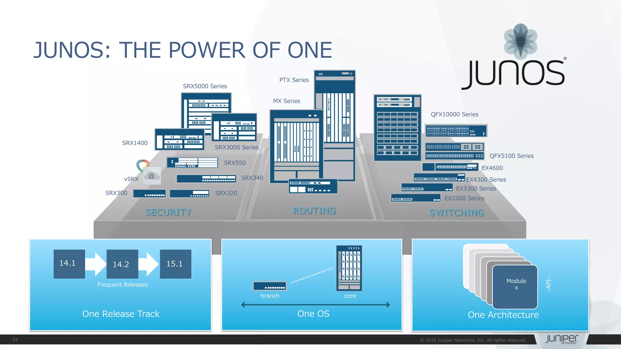


![JUNOS:commit at time オプション
• 設定反映の時間指定(メンテナンスタイムにおける設定反映)
• commit at xx:xx:xx (time) コマンドでcommitすると、指定した時間に設定
ファイルをActivateすることが可能となります
[edit]
mike@jnpr1# commit at 02:00:00
commit check succeeds
commit will be executed at 2016-02-02 02:00:00 UTC
Exiting configuration mode
mike@jnpr1>
xxxxx
xxxxx
xxxxx
...
メンテナンスタイムにCommitが自動的に実施されるため、
管理者が該当の時間に操作する必要はなし](https://image.slidesharecdn.com/junoshandsontrainingex-160720155953/75/EX-QFX-JUNOS-EX-QFX-30-2048.jpg)
![JUNOS:commit confirmed オプション
• 設定の自動復旧機能(ヒューマンエラーによるトラブル防止のため)
• commit confirmed コマンドでcommitすると、再度commitしない限り
default10分で元のconfigにrollbackします
– 指定した時間あるいはdefaultの10分以内に2度目のcommitを入れることで、
configは完全に格納されます
[edit]
root@lab# commit confirmed 5
commit confirmed will be automatically rolled back in 5 minutes unless
confirmed
commit complete
Remote
WAN
誤ったアクセスコントロール設定
xxxxx
xxxxx
xxxxx
...
[edit]
root@lab# commit confirmed 5
commit confirmed will be automatically rolled back in 5 minutes unless
confirmed
commit complete
設定間違いのままcommitしてしまいSSHなどが繋がらなくなってしまった後も、
一定時間のあと1つ前のconfigに自動復旧するため、リモートデバイスのポリシー変更時などに便利](https://image.slidesharecdn.com/junoshandsontrainingex-160720155953/75/EX-QFX-JUNOS-EX-QFX-31-2048.jpg)


![Configurationモード
• Operationalモードにてconfigureと投入することでConfigurationモード
へ移行します
root@lab> configure
Entering configuration mode
[edit]
root@lab#
root@lab> configure
Entering configuration mode
Current configuration users:
fbrooks terminal d0 on since 1999-10-14 07:11:29 UTC,
idle 00:00:49 [edit protocols ospf]
The configuration has been changed but not committed
[edit]
root@lab#
• 他のユーザがconfigurationモードに入っていれば、以下の様に表示されます](https://image.slidesharecdn.com/junoshandsontrainingex-160720155953/75/EX-QFX-JUNOS-EX-QFX-44-2048.jpg)


![コンソール画面出力に関する操作 | no-more
• 通常、出力はCLIのスクリーンサイズを考慮して行われます。出力内容が多い場合、CLI画面
に---(more)---を表示し、出力を一時停止します。ログ取得時などは“ | no-more” オプ
ションを使用し、全て一度に表示することが可能です
[edit]
root@lab> show configuration | no-more
## Last commit: 2016-01-25 11:25:54 JST by root
version 10.4R7.5;
groups {
Japan_team {
system {
backup-router 172.16.1.1;
time-zone Asia/Tokyo;
dump-on-panic;
root-authentication {
encrypted-password "$1$YrXW4H1t$0Ry0FagjB/wMKbVM1izGf/";
## SECRET-DATA
}
login {
user lab {
uid 2000;
"$1$4TDfGIs7$.wTBpcNviWRCebbvcSLzv."; ## SECRET-DATA
:](https://image.slidesharecdn.com/junoshandsontrainingex-160720155953/75/EX-QFX-JUNOS-EX-QFX-54-2048.jpg)


![JUNOS運用管理コマンド
Telnet / SSH : ネットワークに接続された機器を操作する
>telnet アドレス + オプション
例: 172.27.112.161: port 23へtelnetを実施
> traceroute 8.8.8.8 interface ge-0/0/0
traceroute to 8.8.8.8 (8.8.8.8), 30 hops max, 40 byte packets
1 172.27.112.2 (172.27.112.2) 4.394 ms 1.814 ms 2.209 ms
(snip)
13 google-public-dns-a.google.com (8.8.8.8) 4.276 ms 4.286 ms 4.063 ms
Traceroute : ネットワークの経路確認をする
>traceroute アドレス + オプション
例: 8.8.8.8へge-0/0/0からtrace routeを実施
> telnet 172.27.112.161 port 23
Trying 172.27.112.161...
Connected to 172.27.112.161.
Escape character is '^]'.
srx300beta (ttyp0)
login:](https://image.slidesharecdn.com/junoshandsontrainingex-160720155953/75/EX-QFX-JUNOS-EX-QFX-61-2048.jpg)


![編集中の設定確認(show | compare)
• show | compare コマンド:編集中の設定と稼動中の設定を比較します
• 過去のconfigと編集中の設定を比較することも可能
user@lab# set interfaces ge-0/0/0 unit 0 family inet address 192.168.1.1/24
user@lab# show | compare
[edit interfaces]
+ ge-0/0/0 {
+ unit 0 {
+ family inet {
+ address 192.168.1.1/24;
+ }
+ }
+ }
Active
Configuration
(rollback 0)
Candidate
Configuration
# show | compare
user@lab# show | compare rollback [1-49]
Active configと比較して、ge-0/0/0にIPアドレスが追加されている
+:追加
ー:削除](https://image.slidesharecdn.com/junoshandsontrainingex-160720155953/75/EX-QFX-JUNOS-EX-QFX-72-2048.jpg)
![設定ファイルの復旧(rollback)
• rollback コマンド:設定ファイルの復旧を行います
• 変更した設定ファイルを破棄したい場合は、Rollbackコマンドを投入します。(rollbackはrollback 0の略)
• rollback n(0-49)でファイル番号を指定すると、過去の設定をCandidate Configにコピーすることが可能
で、容易に過去の状態に戻すことが可能です。(過去50世代分の設定ファイルを自動保存)
user@lab# rollback
user@lab# rollback ?
Possible completions: <[Enter]> Execute this command
0 2016-07-14 08:41:21 JST by root via cli
1 2016-07-13 16:01:54 JST by root via cli
2 2016-07-13 15:59:51 JST by root via cli
3 2016-07-13 15:57:33 JST by root via cli
4 2016-07-13 15:57:20 JST by root via cli commit confirmed, rollback in 2mins
5 2016-07-12 15:21:37 JST by lab via netconf
6 2016-07-08 16:35:39 JST by lab via cli
7 2016-06-22 19:30:53 JST by lab via cli
8 2016-06-22 19:28:39 JST by lab via cli
9 2016-06-22 19:28:18 JST by lab via cli
…(snip)](https://image.slidesharecdn.com/junoshandsontrainingex-160720155953/75/EX-QFX-JUNOS-EX-QFX-73-2048.jpg)
![commit オプション(commit confirmed / at)
• commit confirmed コマンド:一時的に設定を反映します
• 変更を確定する場合は、時間内にcommitを実行します
• デフォルトでは10分(指定可能)
• 時間までにcommitされなければ、自動的にcommit前の状態に戻る
• commit at コマンド:日時を指定してcommitの実行を予約します
• hh:mm:[ss] または “yyyy-mm-dd hh:mm:[ss]”
user@lab# commit confirmed 5
configuration check succeeds
commit confirmed will be automatically rolled back in 5 minutes unless confirmed
commit complete
# commit confirmed will be rolled back in 5 minutes
user@lab# commit at "2016-04-20 00:00"
configuration check succeeds
commit at will be executed at 2016-04-20 00:00:00 JST
Exiting configuration mode
※予約をキャンセルしたいときは、Operationalモードからclear system commit コマンドを実行](https://image.slidesharecdn.com/junoshandsontrainingex-160720155953/75/EX-QFX-JUNOS-EX-QFX-74-2048.jpg)

![user@lab# load set terminal
[Type ^D at a new line to end input]
set services security-intelligence profile feeds-cc-p1 category CC
set services security-intelligence profile feeds-cc-p1 default-rule then action permit
set services security-intelligence profile feeds-cc-p1 default-rule then log
set services security-intelligence profile Inf-hosts category Infected-Hosts
set services security-intelligence profile Inf-hosts default-rule then action permit
set services security-intelligence profile Inf-hosts default-rule then log
set services security-intelligence policy pol-cc CC feeds-cc-p1
set services security-intelligence policy pol-cc Infected-Hosts Inf-hosts
set services advanced-anti-malware policy skyatp_test match application HTTP
set services advanced-anti-malware policy skyatp_test match verdict-threshold 3
set services advanced-anti-malware policy skyatp_test then action permit
set services advanced-anti-malware policy skyatp_test then notification log
set services advanced-anti-malware policy skyatp_test inspection-profile test
set services advanced-anti-malware policy skyatp_test fallback-options action permit
set services advanced-anti-malware policy skyatp_test fallback-options notification log
set services advanced-anti-malware policy skyatp_test whitelist-notification log
set services advanced-anti-malware policy skyatp_test blacklist-notification log
load complete
Configurationのロード(load set terminal)
• load set terminal コマンド:CLIで追加のsetコンフィグを貼り付けるときに使用
• setコマンドの大量コピー&ペースト時にconfigのとりこぼしが防げます
CTRL+D
貼り付けたいconfigを
terminal上でペースト
し、最後に改行してか
らCTRL+Dを押して読
み込む
キャンセルしたい場合
はCTRL+Cで抜ける](https://image.slidesharecdn.com/junoshandsontrainingex-160720155953/75/EX-QFX-JUNOS-EX-QFX-76-2048.jpg)
![[edit]
user@lab# load merge terminal
[Type ^D at a new line to end input]
protocols {
ospf {
export static-route;
area 0.0.0.0 {
interface ge-0/0/0.0;
interface ge-0/0/1.0;
interface ge-0/0/2.0;
interface lo0.0 {
passive;
}
}
}
}
policy-options {
policy-statement static-route {
from {
protocol static;
route-filter 10.1.1.0/24 longer;
}
then accept;
}
}
load complete
• load merge terminal コマンド:CLIで追加のconfigを貼り付けるときに使用
• 大量のコピー&ペースト時にもconfigのとりこぼしが防げます、最上位の階層から追加の
configを投入する階層までのパスが全部必要です
• relative オプションを付けると今いる階層に応じてconfigの階層もショートカットされます
Configurationのロード(load merge terminal)
interfaces, protocolsや
policy-optionsなど最上位
の構文から記述していく
[edit protocols ospf]
lab# load merge terminal relative
[Type ^D at a new line to end input]
area 0.0.0.0 {
interface xe-1/0/0.0;
}
area 0.0.0.1 {
stub default-metric 10 no-summaries;
area-range 192.168.16.0/20;
interface ge-0/0/3.0;
}
area 0.0.0.2 {
nssa {
default-lsa {
default-metric 20;
metric-type 1;
type-7;
}
no-summaries;
area-range 172.16.12.0/22;
}
area-range 192.168.48.0/20;
}
load complete
CTRL+D
protocols ospfの階層
に移動しareaのconfig
だけ追加
protocols { ospf { の
記述は不要
CTRL+D](https://image.slidesharecdn.com/junoshandsontrainingex-160720155953/75/EX-QFX-JUNOS-EX-QFX-77-2048.jpg)


![コマンド補完と構文エラー
• コマンド補完機能
• Spaceキー/ Tabキー:固定値を補完
• Tabキーはユーザが定義したpolicy名やFilter名の補完も可能
• 構文エラーの通知
• 構文に誤りがあるとsyntax errorと表示される
• ^ マークはエラーとなる項目を示す
user@lab# set interfaces ge-0/0/0 unit 0 family inet filter input ?
Possible completions:
TEST [firewall family inet filter]
user@lab# set interfaces ge-0/0/0 unit 0 family inet filter input T[tab]
user@lab# load replase
^
syntax error, expecting <command>.](https://image.slidesharecdn.com/junoshandsontrainingex-160720155953/75/EX-QFX-JUNOS-EX-QFX-80-2048.jpg)


![インタフェース設定
• インタフェースの設定は物理プロパティの設定と論理プロパティの設定に分か
れます
• 物理プロパティの設定
• データリンクプロトコル
• リンクスピード、半/全2重通信
• MTU
• 論理プロパティの設定
• プロトコルファミリー
• inet (IPv4の設定)
• inet6 (IPv6の設定)
• mpls
• ethernet-switching
interfaces {
interface-name {
physical-properties;
[…]
unit unit-number {
logical-properties;
[…]
}
}
}
インタフェース名配下に
物理プロパティを設定
Unit#配下に
論理プロパティを設定](https://image.slidesharecdn.com/junoshandsontrainingex-160720155953/75/EX-QFX-JUNOS-EX-QFX-93-2048.jpg)


![管理者側から強制的にインタフェースを落とす方法
• Disableコマンドを使用してインタフェースを落とす
root# set interfaces ge-0/0/2 disable
[edit]
root# commit
commit complete
Admin(オペレーター)モードの操作の確認
root# show interfaces
ge-0/0/2 {
disable;
unit 0 {
family inet {
address 140.0.0.12/24;
• Disableコマンドを消去してインタフェースをあげる
root# delete interfaces ge-0/0/2 disable
[edit]
root# commit
commit complete
root# run show interfaces terse
Interface Admin Link Proto Local
Remote
ge-0/0/0 up up
ge-0/0/1 up down
ge-0/0/2 down down
root# run show interfaces terse
Interface Admin Link Proto Local
Remote
ge-0/0/0 up up
ge-0/0/1 up down
ge-0/0/2 up up
admin(オペレータ)の強制的な
インタフェースのダウン](https://image.slidesharecdn.com/junoshandsontrainingex-160720155953/75/EX-QFX-JUNOS-EX-QFX-98-2048.jpg)

![Static Routeの設定
設定例
[edit routing-options]
root# show
static {
route 0.0.0.0/0 next-hop 172.30.25.1;
route 172.28.102.0/24 {
next-hop 10.210.11.190;
no-readvertise;
}
}
IPv4デフォルトルートの設定
経路を広報させないための設定
マネージメント用の経路などに利用
# set routing-options static route <あて先アドレス>next-hop <ネクストホップアドレス>
# set routing-options static route <あて先アドレス>オプション設定
• Static route設定](https://image.slidesharecdn.com/junoshandsontrainingex-160720155953/75/EX-QFX-JUNOS-EX-QFX-100-2048.jpg)
![• 同じあて先にstatic routeを設定する場合はqualified-next-hopの
オプションを利用しpreference(優先)の設定を施します
[edit routing-options]
root# show
static {
route 0.0.0.0/0 {
next-hop 172.30.25.1;
qualified-next-hop 172.30.25.5 {
preference 7;
}
}
}
制限付きネクストホップの設定
Network A
172.29.100.0/24 .1
.1.2
172.30.25.0/30
ge-0/0/1
172.30.25.4/30
.5.6
ge-1/0/0
primary
secondary
Internet
Primary route
※Juniperのstatic routeのpreferenceは5
例: インターネット接続のためのデフォルトルートの設定
Secondary route
※preferenceを7に設定することで優先度を下げる](https://image.slidesharecdn.com/junoshandsontrainingex-160720155953/75/EX-QFX-JUNOS-EX-QFX-101-2048.jpg)
![• showコマンドでstatic routeを確認する
root> show route protocol static
inet.0: 4 destinations, 4 routes (4 active, 0 holddown, 0 hidden)
+ = Active Route, - = Last Active, * = Both
0.0.0.0/0 *[Static/5] 00:41:59
> to 172.30.25.1 via ge-0/0/1.0
… デフォルトルート
プロトコルとpreference
ネクストホップのアドレスとインタフェース
Static Routeの確認](https://image.slidesharecdn.com/junoshandsontrainingex-160720155953/75/EX-QFX-JUNOS-EX-QFX-102-2048.jpg)


![管理インタフェース(me0)に対して管理用アドレスを付与します。
– アドレス192.168.1.xx/24(xx = Topologyで指定された第4オクテット)を付与する
show interfacesコマンドで、設定したme0インタフェースのconfigを確認します。
管理インタフェース(me0)へのアドレス付与(設定済)
me0
EX3400 rear view
# set interface me0 unit 0 family inet address 192.168.1.xx/24
{master:0}[edit]
root# show interfaces](https://image.slidesharecdn.com/junoshandsontrainingex-160720155953/75/EX-QFX-JUNOS-EX-QFX-128-2048.jpg)


![Configurationの確認
ここまでで設定したconfiguration全体を確認します。
① Operationalモードから確認
稼働中のActive configを表示します。
② Configurationモードから確認
編集中のcandidate configを表示します。
commit後に設定変更をしていなければ、Active configと同じ内容が表示されます。
lab@Tokyo-1> show configuration
lab@Tokyo-1> show configuration | display set
lab@Tokyo-1> configure
Entering configuration mode
[edit]
lab@Tokyo-1# show
lab@Tokyo-1# show | display set
同じConfigを異なる形式で表示
同じConfigを異なる形式で表示](https://image.slidesharecdn.com/junoshandsontrainingex-160720155953/75/EX-QFX-JUNOS-EX-QFX-132-2048.jpg)


![Configurationをファイルに保存
次のLabを始める前に、saveコマンドでconfiguration fileをsaveします。
file listコマンドで正常にsaveできたことを確認します。
lab@Tokyo-1# save lab1-end_YYMMDD
Wrote 213 lines of configuration to 'lab1-end_YYMMDD'
{master:0}[edit]
lab@Tokyo-1# exit
Exiting configuration mode
lab@Tokyo-1> file list
/var/home/lab/:
.ssh/
lab1-end_YYMMDD](https://image.slidesharecdn.com/junoshandsontrainingex-160720155953/75/EX-QFX-JUNOS-EX-QFX-136-2048.jpg)


![インタフェース/VLAN/LACP動作確認
インタフェース, VLAN, LACPの確認コマンドで正常性を確認します。
隣接機器に対してpingを実施し、応答があることを確認します。
• ping [隣接機器のIRB IPアドレス]
– Ctrl+Cで停止
> show interfaces (terse)
> show ethernet-switching interfaces
> show vlans (detail)
> show lacp interfaces](https://image.slidesharecdn.com/junoshandsontrainingex-160720155953/75/EX-QFX-JUNOS-EX-QFX-147-2048.jpg)


![①Firewall Filterを使用してtelnetを制御
Firewall Filterを設定します。
Filterをae0インタフェースへ適用します。
Filterが有効なことを確認するため、telnetで隣接機器にアクセスします。
telnet以外の通信(ping, OSPF)は依然可能なことを確認します。
Filterでdiscardされたtelnetのカウンタを確認します。
set firewall family ethernet-switching filter deny_telnet term t10 from ip-protocol tcp
set firewall family ethernet-switching filter deny_telnet term t10 from destination-port telnet
set firewall family ethernet-switching filter deny_telnet term t10 then discard
set firewall family ethernet-switching filter deny_telnet term t10 then count telnet_count
set firewall family ethernet-switching filter deny_telnet term t20 then accept
set interfaces ae0 unit 0 family ethernet-switching filter input deny_telnet
lab@Tokyo> telnet 10.1.1.3
Trying 10.1.1.3...
[Ctrl+Cで停止]
> show firewall](https://image.slidesharecdn.com/junoshandsontrainingex-160720155953/75/EX-QFX-JUNOS-EX-QFX-161-2048.jpg)


![root@Juniper> show virtual-chassis ?
Possible completions:
<[Enter]> Execute this command
active-topology Virtual chassis active topology
device-topology PFE device topology
login
mode Virtual chassis mode information
protocol Show virtual chassis protocol information
status Virtual chassis information
vc-path Show virtual-chassis packet path
vc-port Virtual chassis port information
| Pipe through a command
{master:0}
Virtual Chassisの確認方法について-1
lab@lab> show virtual-chassis?](https://image.slidesharecdn.com/junoshandsontrainingex-160720155953/75/EX-QFX-JUNOS-EX-QFX-187-2048.jpg)


![{master:0}[edit]
root@Tokyo-1# run request system reboot member 0 at now
Reboot the system at now? [yes,no] (no) yes
⑤Virtual Chassis HA
• 確認方法
(VC-1のMaster REをRebootしたときに、対向のVC-2側のOSPF neighborが切れないことを確認)
{master:0}[edit]
root@Tokyo-2# run show ospf neighbor detail
Address Interface State ID Pri Dead
10.1.1.1 ae0.0 Full 1.1.1.1 128 38
Area 0.0.0.0, opt 0x52, DR 10.1.1.2, BDR 10.1.1.1
Up 00:03:24, adjacent 00:03:24
VC-1 (192.168.1.1)
VC-2 (192.168.1.5)](https://image.slidesharecdn.com/junoshandsontrainingex-160720155953/75/EX-QFX-JUNOS-EX-QFX-210-2048.jpg)


![俳句の表示
検証作業やトラブルシュートに疲れたときには、JUNOSに前向きな気持ちの言葉を
表示させ、管理者の気持ちを和らげることが可能です
root> show version and haiku
※コマンドを打つ度、異なった前向きなポエムが表示される
root> show version and haiku
Model: ex2200-c-12p-2g
Junos: 14.1X53-D25.2
JUNOS EX Software Suite [14.1X53-D25.2]
JUNOS FIPS mode utilities [14.1X53-D25.2]
JUNOS Online Documentation [14.1X53-D25.2]
JUNOS EX 2200 Software Suite [14.1X53-D25.2]
JUNOS Web Management Platform Package
[14.1X53-D25.2]
Look, mama, no hands!
Only one finger typing.
Easy: commit scripts.
root> show version and haiku
Model: ex2200-c-12p-2g
Junos: 14.1X53-D25.2
JUNOS EX Software Suite [14.1X53-D25.2]
JUNOS FIPS mode utilities [14.1X53-D25.2]
JUNOS Online Documentation [14.1X53-D25.2]
JUNOS EX 2200 Software Suite [14.1X53-D25.2]
JUNOS Web Management Platform Package
[14.1X53-D25.2]
Juniper babies
The next generation starts
Gotta get more sleep
root> show version and haiku
Model: ex2200-c-12p-2g
Junos: 14.1X53-D25.2
JUNOS EX Software Suite [14.1X53-D25.2]
JUNOS FIPS mode utilities [14.1X53-D25.2]
JUNOS Online Documentation [14.1X53-D25.2]
JUNOS EX 2200 Software Suite [14.1X53-D25.2]
JUNOS Web Management Platform Package
[14.1X53-D25.2]
Weeks of studying,
Days of lab exercises:
JNCIE.](https://image.slidesharecdn.com/junoshandsontrainingex-160720155953/75/EX-QFX-JUNOS-EX-QFX-214-2048.jpg)


![wildcard range set/delete -1
• wildcard rangeコマンドを使用することで、インタフェースなど複数の対象に
対して同じ設定内容を適用することが簡単に可能
root# show interfaces
root#
root# wildcard range set interfaces ge-0/0/[0-3,5,!2] mtu 9000
root# show interfaces
ge-0/0/0 { mtu 9000; }
ge-0/0/1 { mtu 9000; }
ge-0/0/3 { mtu 9000; }
ge-0/0/5 { mtu 9000; }
ge-0/0/0-1,3,5のMTU設定が一括で投入されている
[0-3, 5, !2] ⇒ 0~3と5、ただし2は除く](https://image.slidesharecdn.com/junoshandsontrainingex-160720155953/75/EX-QFX-JUNOS-EX-QFX-219-2048.jpg)
![wildcard range set/delete -2
• 同様にDeleteも可能
root# wildcard range delete interfaces ge-0/0/[0-1] mtu
root# show interfaces
ge-0/0/0 { mtu 9000; }
ge-0/0/1 { mtu 9000; }
ge-0/0/3 { mtu 9000; }
ge-0/0/5 { mtu 9000; }
root# show interfaces
ge-0/0/3 { mtu 9000; }
ge-0/0/5 { mtu 9000; }](https://image.slidesharecdn.com/junoshandsontrainingex-160720155953/75/EX-QFX-JUNOS-EX-QFX-220-2048.jpg)


![階層間の移動 -1
同じ階層の設定を複数作成する際は階層を移動することで作成する構文を省略する
ことが可能です
例1: FWフィルタの設定(topの階層から設定)
[edit]
set firewall family inet filter FW-FILTER term BLOCK from source-address 10.10.10.0/24
set firewall family inet filter FW-FILTER term BLOCK from destination-address 192.168.1.0/24
set firewall family inet filter FW-FILTER term BLOCK from dscp cs5
set firewall family inet filter FW-FILTER term BLOCK from port https
set firewall family inet filter FW-FILTER term BLOCK from port http
# show firewall
family inet{
filter FW-FILTER{
term BLOCK{
from{
source-address{
10.10.10.0/24;
}
destination-address{
192.168.1.0/24;
}
dscp cs5;
port[ https http ];
}
}
}
}
※設定を投入する際は繰り返しset firewall family…fromと入力する必要がある](https://image.slidesharecdn.com/junoshandsontrainingex-160720155953/75/EX-QFX-JUNOS-EX-QFX-223-2048.jpg)
![# show firewall
family inet {
filter FW-FILTER {
term BLOCK {
from {
source-address {
10.10.10.0/24;
}
destination-address {
192.168.1.0/24;
}
dscp cs5;
port [ https http ];
}
}
}
}
[edit firewall family inet filter FW-FILTER term BLOCK from]
set source-address 10.10.10.0/24
set destination-address 192.168.1.0/24
set dscp cs5
set port https
set from port http
階層間の移動 -2
例2: FWフィルタの設定(firewall filter FW-FILTER term BLOCK fromの階層から設定)
※設定を投入する際はfirewall family…fromまでを省略して入力することができる
※コマンド入力時、set や delete、show の前に top や up <階層数> を入れると
今いる階層から移動せずに今いる階層を無視して入力・表示することができる](https://image.slidesharecdn.com/junoshandsontrainingex-160720155953/75/EX-QFX-JUNOS-EX-QFX-224-2048.jpg)
![階層間の移動 -3
• 階層間は、editコマンドで移動することができます
• exit:直前にいたレベルに戻ります
• TOPでEXITを実行すると、Operationalモードに戻ります
• OperationalモードでEXITを実行すると、システムからLogoutします
• Shellモードから`cli`でOperationalモードに移動した場合は、Shellモードに戻ります
• up:一つ上のレベルに移動します
• top:最上位のレベルに移動します
# show firewall
family inet{
filter FW-FILTER{
term BLOCK{
from{
source-address{
10.10.10.0/24;
}
destination-address{
192.168.1.0/24;
}
dscp cs5;
port[ https http ];
}
}
}
}
Top
Down
Editで階層を指定
Topで最上位へ
upで一つ上へ
※top edit や up <階層数> edit と入れると1回の入力で
今いる階層から任意の階層に移動することができる](https://image.slidesharecdn.com/junoshandsontrainingex-160720155953/75/EX-QFX-JUNOS-EX-QFX-225-2048.jpg)

![annotate
• annotateコマンドを使うと、自由に注釈をつけることが可能、
テスト時・運用時などに便利
今いる階層の直下にあるコンフィグアイテムが対象、注釈内容はコンフィグアイテムの上部に/* XXXX */と書かれる
root# annotate interfaces ge-0/0/0 “borrowed the cable directory from Yoshida-san”
[edit]
lab# edit routing-instances
[edit routing-instances]
lab# annotate cust-1 "L3VPN test"
[edit routing-instances]
lab# edit cust-1
[edit routing-instances cust-1]
lab# annotate protocols
Don'tForgetInjectDirectRoute
[edit routing-instances cust-1]
lab# up
[edit routing-instances]
lab# show
/* L3VPN test */
cust-1 {
instance-type vrf;
interface ge-0/0/0.101;
interface ge-0/0/1.101;
route-distinguisher 192.168.1.1:1001;
vrf-target target:64512:1001;
vrf-table-label;
/* Don'tForgetInjectDirectRoute */
protocols {
bgp {
group cust-1 {
description "Receive-Routes 1000"
(snip)
※コメント内容にスペース(空白)が含まれるときはコメント両端を引用符(" ")でくくる
※コメントを消すときは annotate xxxx "" というように引用符("")で上書きする
※show configuration | display set では表示されない
※コンフィグを張り付けるときに直接 /* xxxx */ 構文を挿入できる](https://image.slidesharecdn.com/junoshandsontrainingex-160720155953/75/EX-QFX-JUNOS-EX-QFX-227-2048.jpg)


![JUNOS : help reference
• コマンドのオンラインマニュアルを参照することが可能
user@host> help reference oam action
action (OAM)
Syntax
action {
syslog (OAM Action);
link-down;
send-critical-event;
}
Hierarchy Level
[edit protocols oam ethernet link-fault-management action-profile]
Release Information
Statement introduced in JUNOS Release 8.5.
…
Description
Define the action or actions to be taken when the OAM fault event occurs.
Usage Guidelines
See Specifying the Actions to Be Taken for Link-Fault Management Events.](https://image.slidesharecdn.com/junoshandsontrainingex-160720155953/75/EX-QFX-JUNOS-EX-QFX-235-2048.jpg)


![設定方法;
• Vlan1001にサーバのデフォルトゲートウェイとなるアドレスを設定します。
• [Option]L3 Routing(Default Gateway)の設定
et-0/0/0 et-0/0/0
et-0/0/22
et-0/0/23
Node1 Node2
ae1
実IP 192.168.1.253/24
仮想IP 192.168.1.254
実IP 192.168.1.252/24
設定項目 Node1 Node2 備考
I/F名 irb unit 1001 irb unit 1001
実IP 192.168.1.253/24 192.168.1.252/24
仮想IP 192.168.1.254 192.168.1.254
Priority 200 100
Accept-data 設定する 設定する
set vlans v1001 l3-interface irb.1001
set interfaces irb unit 1001 family inet address 192.168.1.253/24 vrrp-group 1 virtual-address 192.168.1.254
set interfaces irb unit 1001 family inet address 192.168.1.253/24 vrrp-group 1 priority 100
set interfaces irb unit 1001 family inet address 192.168.1.253/24 vrrp-group 1 accept-data
※Node1の設定例](https://image.slidesharecdn.com/junoshandsontrainingex-160720155953/75/EX-QFX-JUNOS-EX-QFX-269-2048.jpg)
![設定方法;
• Default Gatewayアドレスが冗長されているか確認します。
• 下記の様になっていない場合
– ICL(ae0)にVLAN1001が設定されているか確認して下さい。
• L3 Routing(Default Gateway)の確認
et-0/0/0 et-0/0/0
et-0/0/22
et-0/0/23
Node1 Node2
ae1
実IP 192.168.1.253/24
仮想IP 192.168.1.254
実IP 192.168.1.252/24
Node1
Node2
ae0
{master:0}[edit]
lab@node1# run show vrrp
Interface State Group VR state VR Mode Timer Type Address
irb.1001 up 1 master Active A 0.359 lcl 192.168.1.253
vip 192.168.1.254
lab@node2# run show vrrp
Interface State Group VR state VR Mode Timer Type Address
irb.1001 up 1 backup Active D 2.718 lcl 192.168.1.252
vip 192.168.1.254
mas 192.168.1.253](https://image.slidesharecdn.com/junoshandsontrainingex-160720155953/75/EX-QFX-JUNOS-EX-QFX-270-2048.jpg)


![[G-Tech2014講演資料] シスコのSDN最新動向とITインフラエンジニアに求められるスキル - シスコシステムズ合同会社](https://cdn.slidesharecdn.com/ss_thumbnails/d-2sdnit-141020222301-conversion-gate01-thumbnail.jpg?width=640&height=640&fit=bounds)


