Risk Assessment For Installation of Drainage Pipes.pdf
Iso Knowledge Sharing_NK1250_NK1220.pptx
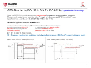
1. GPS Standards (ISO 1101 / DIN EN ISO 8015) – Applies to all Hauni drawings.
Since the 01.01.2012, the following applies internationally for drawings without drawing indication:
Measurements are performed according to the Principle of Independence (GPS Geometrical Product
Specification) in accordance with DIN EN ISO 8015 (or ISO 8015).
The following applies for drawings in the BA Tobacco:
------>---------->---------->---------->----------> I---------->---------->---------->--------->---------->---------
>
Drawings created before 30.06.2014
DIN 7167 without drawing indication
(Old drawing revision)
For drawings created on or after 01.07.2014
Indication of DIN EN ISO 8015 or
DIN EN ISO 14405 Ⓔ in title block
DIN EN ISO 8015 (NK1250-t0):
Ⓔ = Envelope requirement restriction for individual dimensions / ISO fits. (Precision holes and shaft)
1
Old drawing (without drawing indication) New drawing (with drawing indication)
2. Reference:
NK1220, Part 2 , Page 5 to 8 – 4 Geometry and position (Applied to all drawings without drawing indication).
2
3. Drawing Entries (NK1250-t2):
What we need to measure / measuring result? :
Example: (Refer to NK1250-t2, page 10 to 15 for details)
Flatness
Flatness
Flatness
Flatness
Flatness / straightness
Flatness / straightness
+ Parallelism between two surface
3
4. DIN EN ISO 8015 (NK1250-t3):
Statistical size
Size that is obtained from a homogeneous set of localised or calculated sizes, using
statistical methods.
Refer to NK1250, Part 3 – Page 3 of 8 for details.
4
5. DIN EN ISO 8015 (NK1250-t3):
Statistical size (Hole & shaft)
- Details of measuring point:
P1
P2
P3
Note: Point to measure : 3 point (P1, P2 & P3 - Based on the length of the shaft / depth of the hole)
● P1 – 1mm to 5mm from the top surface (Based on CMM probing size and hole chamfer size).
● P2 – At the middle / half of the hole depth.
● P3 – 1mm to 5mm from the bottom surface (Based on CMM probing size and hole chamfer size)
● Roundness to be applied according to NK1220, Part 2 (4.1.2 Roundness).
● Straightness to be applied according to NK1220, Part 2 (4.1.1 Straightness and flatness) – Especially for
the shaft.
5
6. What we need to measure / measuring result? :
Precision holes / shaft result must have (CMM program):
1.
2.
Diameter.
Roundness – Generate graphic (to review result).
Tolerance: Half of the shaft / hole spec. (Tolerance ÷ 2) – Refer to NK1220 for details.
2 point diameter (to review “Statistical size”).
3.
Select Ⓔ = Envelope / ISO fits.
4.
Tolerance:
According to
shaft / hole spec.
2 point diameter measuring result:
SX
CMM measuring result
SN
Info:
SX (Maximum diameter) = Actual fitting size for shaft.
SN (Minimum diameter) = Actual fitting size for hole.
CMM measuring result (Nominal diameter) = Average
between SX and SN.
Note: Supplier need to submit the measurement result with
the part during delivery (Print out the CMM measuring result).
Minimum requirement: Diameter + roundness.
6
7. Sample of the CMM measuring result – Graphic generate for roundness:
Tolerance (Max)
Tolerance (Min)
Nominal diameter
Actual hole / shaft condition
(Scanning)
SN
(Actual Minimum diameter)
SX
(Actual Maximum diameter)
7
8. ISO 1101:2017 (E)
Geometrical Product Specification (GPS) Standard.
Focus Concepts:
1. Tolerance Zone – Space limited by and including one or two ideal lines or surface, and
characterized by one or more linear dimensions, called a tolerance.
Intersection Plane – Established from an extracted feature of the workpiece, identifying a line
on an extracted surface (integral or median) or a point on an extracted line.
Orientation Plane – Established from an extracted feature of the workpiece, identifying the
orientation of the tolerance zone.
Direction Feature – Established from an extraction feature of the workpiece, identifying the
direction of local deviations.
Compound Continuous Feature – Single feature composed of more than one single feature
joined together without gaps.
Collection Plane – Established from a feature on the workpiece, defining a closed compound
continuous feature.
Theoretically Exact Dimension (TED) – Linear or angular dimension used in GPS operations
to define theoretically exact geometry, extents, locations and orientations of features.
Theoretically Exact Feature (TEF) – Nominal feature with ideal shape, size, orientation and
location, as applicable.
United Feature – Compound integral feature which may or may not be continuous, considered
as a single feature.
2.
3.
4.
5.
6.
7.
8.
9.
8