Download to read offline
![Jayalakshmi et al Int. Journal of Engineering Research and Applications www.ijera.com
ISSN : 2248-9622, Vol. 4, Issue 3( Version 4), March 2014, pp.26-29
www.ijera.com 26 | P a g e
Investigation of Effect of Operating Parameters of A CNC
Cylindrical Grinding Machine on Geometric Dimensioning and
Tolerancing
Jayalakshmi1
, Prof. S.P Joshi2
, Dr. P.M George3
Student, M.E (Machine Design) Mechanical Engg. Department B.V.M Engineering College Vallabh Vidyanagar
Associate Professor Mechanical Engg. Department B.V.M Engineering College Vallabh Vidyanagar
Professor & Head Mechanical Engg. Department B.V.M Engineering College Vallabh Vidyanagar
Abstract
Machining processes are met with dimensional and geometrical variations in a product during machining
operation. The amount of variation needs to be more strictly defined for accurately machined parts. Geometric
dimensioning and tolerancing (GD&T) definition provides the precision required for allowing manufacturing of
most economical parts. Crankshaft flange is required to be machined with higher degree of precision. If
geometrical accuracies are not met the crankshaft-flywheel assembly will cause wear, unbalance and vibration,
leading to poor functionality. The face of crankshaft flange is evaluated for geometric tolerances- flatness and
runout. A two level three factor factorial model is designed and analyzed on Minitab 16 software to identify the
most affecting machining parameter among speed, feed and depth of cut on face flatness and face runout.
Keywords— Crankshaft, Cylindrical grinding, Geometric tolerances, Design of experiments, Flatness, Runout
I. INTRODUCTION
Crankshaft is the mounting structure for the
engine’s flywheel and is considered the most critical
feature. Crankshaft flange is machined first on a CNC
turning machine where its diameter and face are
turned nearly to size and then brought to size on a
CNC cylindrical grinding machine. High product
quality can be achieved through careful selection of
machine tools, their operating parameters and proper
process control.[1]
The operating parameters of grinding process
play the most important role, when the cylindrical
parts are made close to tolerance. Thus, in order to
achieve desirable part quality, the operating
conditions such as job speed, feed rate and depth of
cut, must be carefully decided and optimized for
use.[2]
Flatness and runout are the most common
measurements for identifying the geometrical
accuracy of face of crankshaft flange.
Flatness is a surface form control. A
perfectly flat surface is defined as having all its
elements in the same plane. Flatness feature control
frames create a tolerance zone which consists of the
distance between two parallel lines. This control is
useful in achieving surfaces capable of resting on
mating planer surfaces without significant rocking. It
is also used to limit pitting, bumping of a surface.
Runout is a two dimensional control capable
of maintaining within a specified tolerance the
circularity and coaxiality of a feature to a datum axis.
If used on a surface that is 90˚ to the datum axis, it is
capable of controlling wobble of that surface.[3]
The
better geometric control of finished product ensures
proper seating of flywheel preventing unbalance and
wear between mating surfaces.
Design of experiments (DOE) is an efficient
tool and effective way to design the level of
parameters that obtain optimality, since it can
significantly reduce number of experiments while
yielding acceptable results [4]
. The parameter design
for this study is two levels on each factor, job speed,
depth of cut and feed rate. The study herein, has
proposed a predictive empirical model for GD&T
requirements to be used by designers while designing
the crankshaft flange.
II. EXPERIMENTAL WORK
The scope of the study is confined to the
cylindrical grinding machine Cinetic Landis 3SE
CNC 389 series used for machining the crankshaft
flange in Tata’s Nano plant. Fig.1 represents the
dimensional and geometrical tolerances requirements
of the crankshaft flange. The face of the flange is to be
machined within flatness and runout tolerance of
0.05mm and 0.03mm respectively.
Forged microalloyed steel 38MnSiVS5 is
used for making the crankshaft for its better
machinability and weldability.
RESEARCH ARTICLE OPEN ACCESS](https://image.slidesharecdn.com/e43042629-140419005213-phpapp02/85/E43042629-1-320.jpg)
![Jayalakshmi et al Int. Journal of Engineering Research and Applications www.ijera.com
ISSN : 2248-9622, Vol. 4, Issue 3( Version 4), March 2014, pp.26-29
www.ijera.com 27 | P a g e
Fig. 1. Crankshaft flange
A. 2^3DESIGN
The three factors chosen for this experiment
are wheel speed (A), feed rate (B) and depth of cut
(C), each at two levels are of interest. The design is
called 2^3factorial design and the eight treatment
combination are represented in the table1.[5]
In running a two-level factorial experiment
we usually anticipate fitting the first-order model, but
we should be alert to the possibility that the second-
order model is more appropriate. There is a method of
replicating certain points in a 2k
factorial that will
provide protection against curvature from second
order effects as well as allow an independent estimate
of error to be obtained. The method replicate consists
of adding center points to the 2k
design. One important
reason for adding the run at the design center points is
that they do not affect the usual effect estimates in a
23
design.[6]
TABLE1.
23
DESIGN WITH CENTER POINTS
Run A B C Labels
1 - - - (1)
2 + - - a
3 - + - b
4 + + - ab
5 - - + c
6 + - + ac
7 - + + bc
8 + + + abc
9 0 0 0 -
10 0 0 0 -
11 0 0 0 -
12 0 0 0 -
TABLE2.
OPERATING RANGE OF THE VARIABLE PARAMETERS
Machining parameters
defined
Levels
Low (-) High (+)
Job speed (rpm) 110 150
Feed (mm/s) 0.012 0.02
Depth of cut (mm) 0.04 0.10
B. EXPERIMENTAL RESULTS
As per the experimental plan and range
shown in Table2 and 3, the experiments are run at
random. The responses are generated by measuring
the feature in Adcole gage. In Adcole gage, the part is
loaded between centers and is rotated by headstock
spindle, which has an optical angle encoder accurate
to 0.001 degree. The part is measured by a follower
which houses the laser system that takes radial
measurements. Readout of the follower’s position is
made at every 1/10 degree of rotation of the part.
TABLE3.
EXPERIMENTAL RESULTS FOR 23
DESIGN
Sr.
No.
Factors Response
Speed
(rpm)
Feed
(mm/s)
Depth
of Cut
(mm)
Face
flatness
(mm)
Face
runout
(mm)
1 110 0.012 0.04 0.001 0.012
2 150 0.012 0.04 0.003 0.016
3 110 0.020 0.04 0.002 0.015
4 150 0.020 0.04 0.003 0.018
5 110 0.012 0.10 0.003 0.017
6 150 0.012 0.10 0.001 0.021
7 110 0.020 0.10 0.002 0.019
8 150 0.020 0.10 0.004 0.023
9 130 0.016 0.07 0.001 0.017
10 130 0.016 0.07 0.002 0.016
11 130 0.016 0.07 0.002 0.015
12 130 0.016 0.07 0.003 0.013
The results, hence obtained are fed into the
Design Expert software (Minitab) for further analysis.](https://image.slidesharecdn.com/e43042629-140419005213-phpapp02/85/E43042629-2-320.jpg)
![Jayalakshmi et al Int. Journal of Engineering Research and Applications www.ijera.com
ISSN : 2248-9622, Vol. 4, Issue 3( Version 4), March 2014, pp.26-29
www.ijera.com 29 | P a g e
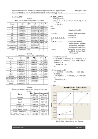
Fig. 3. Main effects plot for face runout
III. CONCLUSIONS
A CNC cylindrical grinding machine is a
precision grinding machine. The investigation herein
has derived relationship of grinding parameters and
geometric tolerances.
Face flatness and face runout errors are least
at 110 rpm, 0.012mm/s feed and 0.04mm depth of cut.
The analysis of variance for face flatness
indicates that since the p-values of all the source of
variations are greater than 5%, it is difficult to state
which parameter significantly affects the face flatness
error. The model hence developed is inadequate.
However it could be used as a means to understand
the most significant parameter that influences the
geometry of the part. The most significant parameters
that influence face flatness are speed and feed,
followed by depth of cut. Interaction is also observed
between speed & feed and speed & depth of cut. In
order to develop an adequate empirical model further
investigation is required with selection of wider range
of variation for parameters.
The analysis of variance for face runout
indicates that since the p-values for speed and depth
of cut are almost equal and less than 5%, they are
most significant parameters. Further investigation is
required to understand the significance of feed with
selection of wider range.
Main effects plot for both geometric
tolerance errors indicate that the errors are minimum
at lower values of the parameters. Face flatness and
face runout errors increase with increase in the speed,
feed and depth of cut.
Adherence to the predicted empirical models
given by, Eqs. (2) and (3), will ensure control of face
flatness and face runout so that economic and efficient
parts are manufactured.
REFERENCES
[1] R K Jain, Production Technology, 17th
Edn,
Khanna Publishers 2009.
[2] Study Performance of Cylindrical Grinding
On Straightness’ by MOHD Affendy Bin
Samdin, Faculty of Manufacturing
Engineering, Universiti Teknikal Malaysia
Melaka; ‘Prediction of surface roughness
and roundness error in cylindrical grinding
by ANN’ by C.K. Dhinakarraj, M.E,
P.Mangaiyarkarasi
[3] James D Meadows, Geometric
Dimensioning and Tolerancing .Vol.2
Marcel Dekker, Inc.
[4] Montgomery D.C, Design and Analysis of
Experiments, 5th Edn, John Wiley & Sons,
2005
[5] Montgomery D.C, Design and Analysis of
Experiments, 5th Edn, John Wiley & Sons,
2005
[6] Montgomery D.C, Design and Analysis of
Experiments, 5th Edn, John Wiley & Sons,
2005
Websites
http://en.wikipedia.org/
http://sciencedirect.com/
http://www.ieee.com/
http://www.google.com/
http://www.emachineshop.com/machine-shop/GD-
T- -Definition/page618.html
http://www.cineticlandis.com/](https://image.slidesharecdn.com/e43042629-140419005213-phpapp02/85/E43042629-4-320.jpg)

This document investigates the effect of operating parameters on the geometric dimensioning and tolerancing (GD&T) of a CNC cylindrical grinding machine, specifically focusing on the crankshaft flange. A factorial design experiment was conducted to analyze the influence of speed, feed rate, and depth of cut on face flatness and runout, with results indicating optimal settings for minimal geometric errors. The study concludes that while the derived predictive models have limitations, they highlight the significance of certain parameters in achieving precise machining results.