Download to read offline
![International Research Journal of Engineering and Technology (IRJET) e-ISSN: 2395-0056
Volume: 07 Issue: 03 | Mar 2020 www.irjet.net p-ISSN: 2395-0072
© 2020, IRJET | Impact Factor value: 7.34 | ISO 9001:2008 Certified Journal | Page 1665
Fig-5: LCD display
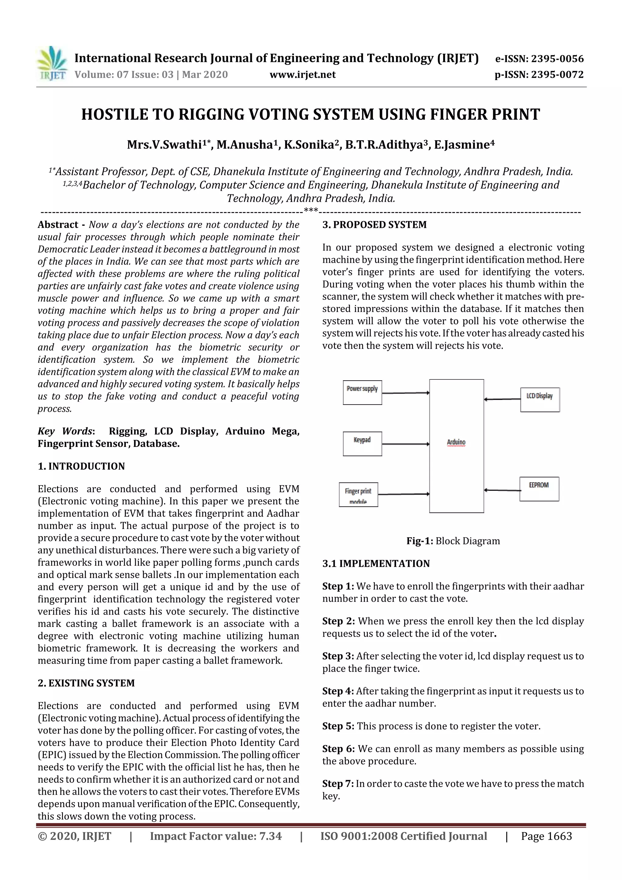
3.5 Fingerprint Scanner:
A fingerprint scanner generally works by first recording
fingerprint scans of all authorized individuals for a specific
system. These scans are saved within a database. The user
who needs access puts their finger on a finger print scanner,
which scans and copies the input from the individual and
appears for any similarity within the already-stored finger
prints. If there's a positive match, the individual is granted
access. Fingerprint scanners most ordinarily use a person's
thumbprint as identification.
Fig-6: Finger print Scanner
4. RESULTS
First we connect the Arduino to our pc with USB. Ourproject
consists of two phases (a) Enrollment (b) Voting process.
A. Enrollment:
The enrollment phase starts by pressingtheenroll button. In
the enrollment process voters aadhar number and
fingerprint will be considered for authentication.
B. Voting Process:
In order to start the voting process we have to press the
match key. It requests us to place the finger for
authentication. It then checks the validity of the voter. If
valid it requests to caste the vote by displaying his details
like aadhar number or else denies voting. If he had already
voted it displays that he had already voted.
5. CONCLUSION
This project is often used for voting since it overcome all the
draw backs of ordinary mechanical device also provide
additional security. Its main advantage is that since
fingerprints of each person is exclusive and hence this
technique completely reduces the prospect of invalid votes.
The system are often manufactured simply also as cheap.
ACKNOWLEDGEMENT
I would like to thank my guide Mrs.V.Swathi (Associate
Professor, Department of Computer Science & Engineering)
for the key guidance, adequate support, time and constant
encouragement towards the project. And also I wouldliketo
thank all co-guides for their constructive suggestions.
REFERENCES
[1] Umang Shah, Trupt Shah, Marteen Kansagara,
Saagar Daxini, Biometric SecuredVotingMachineto
Avoid Bogus Voting Based on AADHAR CARD in
International Journal of Innovative Research in
Computer and Communication Engineering, Vol. 3,
Issue 3, March 2015.
[2] B. Madan Mohan Reddy, D. Srihari, RFID Based
Biometric Voting Machine Linked To Aadhaar For
Safe And Secure Voting in International Journal of
Science, Engineering and Technology Research
(IJSETR) Volume 4, Issue 4, April 2015.](https://image.slidesharecdn.com/irjet-v7i3311-201214140158/85/IRJET-Hostile-to-Rigging-Voting-System-using-Finger-Print-3-320.jpg)
![International Research Journal of Engineering and Technology (IRJET) e-ISSN: 2395-0056
Volume: 07 Issue: 03 | Mar 2020 www.irjet.net p-ISSN: 2395-0072
© 2020, IRJET | Impact Factor value: 7.34 | ISO 9001:2008 Certified Journal | Page 1666
[3] Aanjana Devi.S, Dr.Palanisamy.V, Anandha Jothi.R,
Confidential E-Voting System Using Face Detection
and Recognition in international Journal of
Engineering and Techniques - Volume 3 Issue 4,
July-Aug 2017.
[4] Mahendheran M., V.B.Ajith Rahavan,I. VasuDevan,
T.S. Kiruba Shankar and S.Raja,2016.OnlinePolling
System to This Digital Era with Thumb Press and
Image Capture, Middle-East Journal of Scientific
Research, 24(3): 645-649.
[5] Balaji, Speech of Shri V S Sampath, CEC for Defence
Estates Day Lecture 2014.](https://image.slidesharecdn.com/irjet-v7i3311-201214140158/85/IRJET-Hostile-to-Rigging-Voting-System-using-Finger-Print-4-320.jpg)

This document describes a proposed hostile to rigging voting system using fingerprint identification. The system aims to provide a more secure and fair voting process. It would use fingerprint identification to verify voters' identities instead of relying on manual verification of identification cards. Registered voters' fingerprints and Aadhar numbers would be stored in a database. At voting, the system would check if a voter's fingerprint matches those stored to authenticate them before allowing them to cast a vote. This is intended to reduce the potential for fake or duplicate votes by positively identifying each voter through their biometrics. The system was designed using an Arduino Mega microcontroller, fingerprint sensor, LCD display, and other components.


![EVM_PPT[1].pptx bsjhbsgjygasuygxvashgfxvbgxvytSGXCVhgafsxchAFSDafcdxg](https://cdn.slidesharecdn.com/ss_thumbnails/evmppt1-240720105003-37ced177-thumbnail.jpg?width=640&height=640&fit=bounds)


