Download to read offline


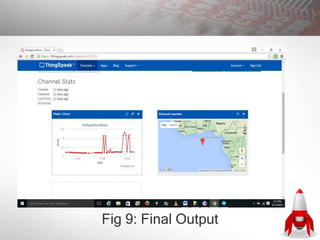
![YunClient client;
#else
#ifdef USE_WIFI_SHIELD
#include <SPI.h>
// ESP8266 USERS -- YOU MUST COMMENT OUT THE LINE BELOW. There's a
bug in the Arduino IDE that causes it to not respect #ifdef when it comes to #includes
// If you get "multiple definition of `WiFi'" -- comment out the line below.
#include <WiFi.h>
char ssid[] = "<YOURNETWORK>"; // your network SSID (name)
char pass[] = "<YOURPASSWORD>"; // your network password
int status = WL_IDLE_STATUS;
WiFiClient client;
#else
// Use wired ethernet shield
#include <SPI.h>
#include <Ethernet.h>
byte mac[] = { 0xDE, 0xAD, 0xBE, 0xEF, 0xFE, 0xED};
EthernetClient client;
#endif
#endif
// On Arduino: 0 - 1023 maps to 0 - 5 volts
#define VOLTAGE_MAX 5.0](https://image.slidesharecdn.com/practicals-200720102534/85/IoT-Platform-23-320.jpg)
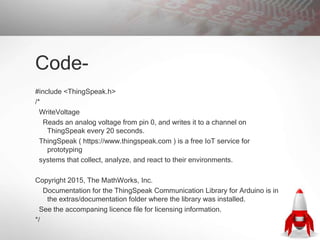
![#define VOLTAGE_MAXCOUNTS 1023.0
#endif
#ifdef ARDUINO_ARCH_ESP8266
#include <ESP8266WiFi.h>
char ssid[] = "<YOURNETWORK>"; // your network SSID (name)
char pass[] = "<YOURPASSWORD>"; // your network password
int status = WL_IDLE_STATUS;
WiFiClient client;
// On ESP8266: 0 - 1023 maps to 0 - 1 volts
#define VOLTAGE_MAX 1.0
#define VOLTAGE_MAXCOUNTS 1023.0
#endif
#ifdef SPARK
TCPClient client;
// On Particle: 0 - 4095 maps to 0 - 3.3 volts
#define VOLTAGE_MAX 3.3
#define VOLTAGE_MAXCOUNTS 4095.0
#endif
/*
*****************************************************************************************](https://image.slidesharecdn.com/practicals-200720102534/85/IoT-Platform-24-320.jpg)
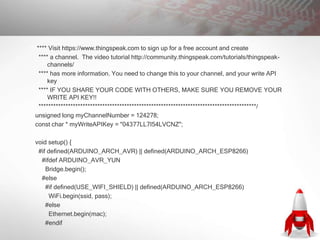
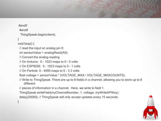
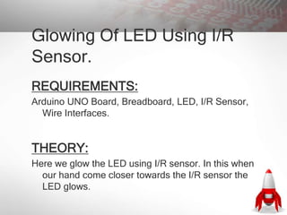
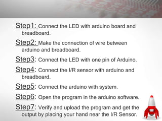
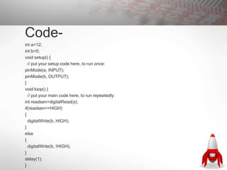


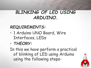
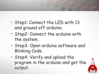
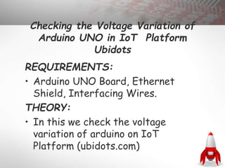
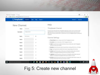
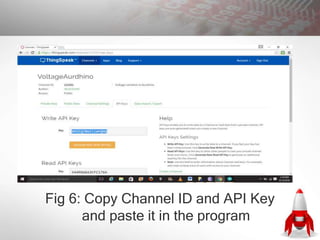
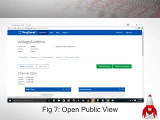
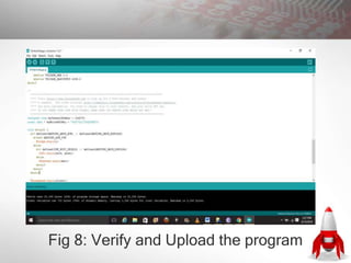
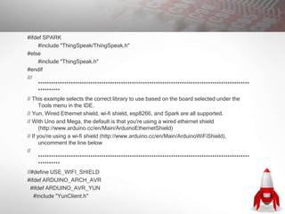
This document contains instructions for several Arduino projects: 1. Blinking an LED using Arduino by connecting the LED to pins on the Arduino board and uploading a blinking code. 2. Checking voltage variations of an Arduino Uno on the IoT platforms Ubidots and ThingSpeak by connecting sensors to read voltage and uploading programs to send data to the platforms. 3. Making an LED glow using an IR sensor connected to an Arduino, with the LED turning on when a hand approaches the sensor.