Download as PDF, PPTX

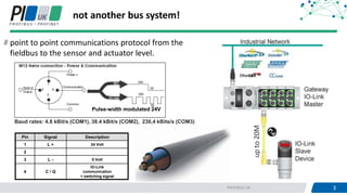
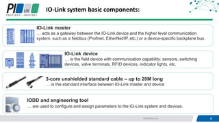
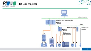

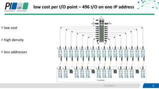
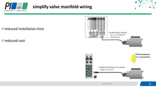
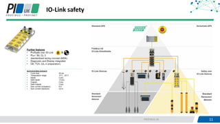

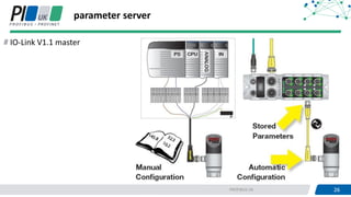
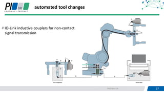
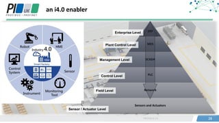
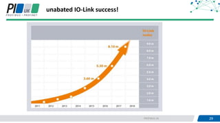

IO-Link is a point-to-point communications protocol for sensors and actuators, offering a standardized interface that enhances industrial automation. It provides low-cost, high-density I/O options while simplifying wiring and installation, leading to improved diagnostics and reduced maintenance. The system comprises IO-Link masters, devices, and configuration tools that facilitate efficient management and integration within various communication networks.


