Download as PDF, PPTX
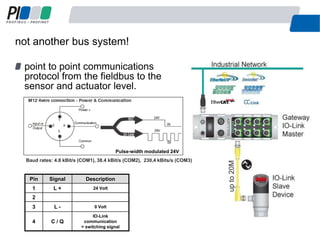
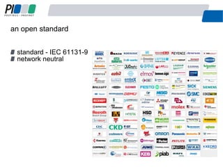
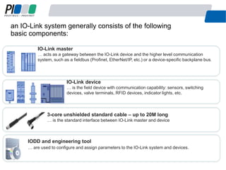
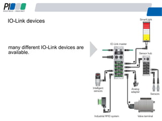
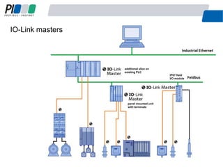
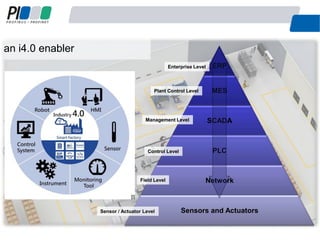


This document introduces IO-Link, a point-to-point communication protocol designed for connecting sensors and actuators to higher-level communication systems. It details the architecture of IO-Link systems, including components such as IO-Link devices and masters, and highlights benefits like easier device handling, reduced costs, and extensive diagnostics. The document emphasizes the importance of IO-Link in modern industrial automation and its role as an enabler for Industry 4.0.


