This paper investigates the design and simulation of UTRA FDD control channels in the presence of noise and various channel models using MATLAB. It tests the performance of different channel models, particularly under AWGN and fading conditions, and compares results via Monte Carlo simulations. The study highlights the complexities and advantages of FDD and TDD in cellular networks, focusing on their implementation and operational characteristics.
![International Journal of Next-Generation Networks (IJNGN) Vol.4, No.3,September 2012
DOI : 10.5121/ijngn.2012.4304 45
INVESTIGATION OF UTRA FDD DATA AND
CONTROL CHANNELS IN THE PRESENCE OF NOISE
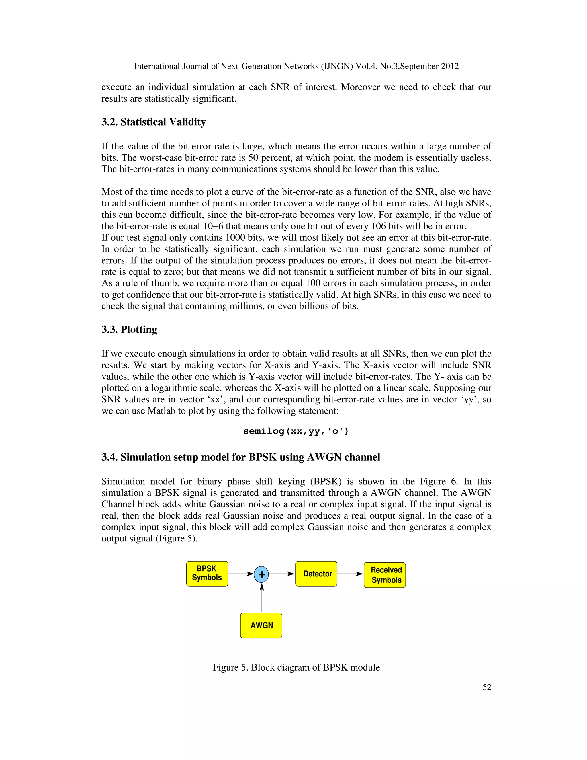
AND STANDARD DEFINED CHANNEL MODELS
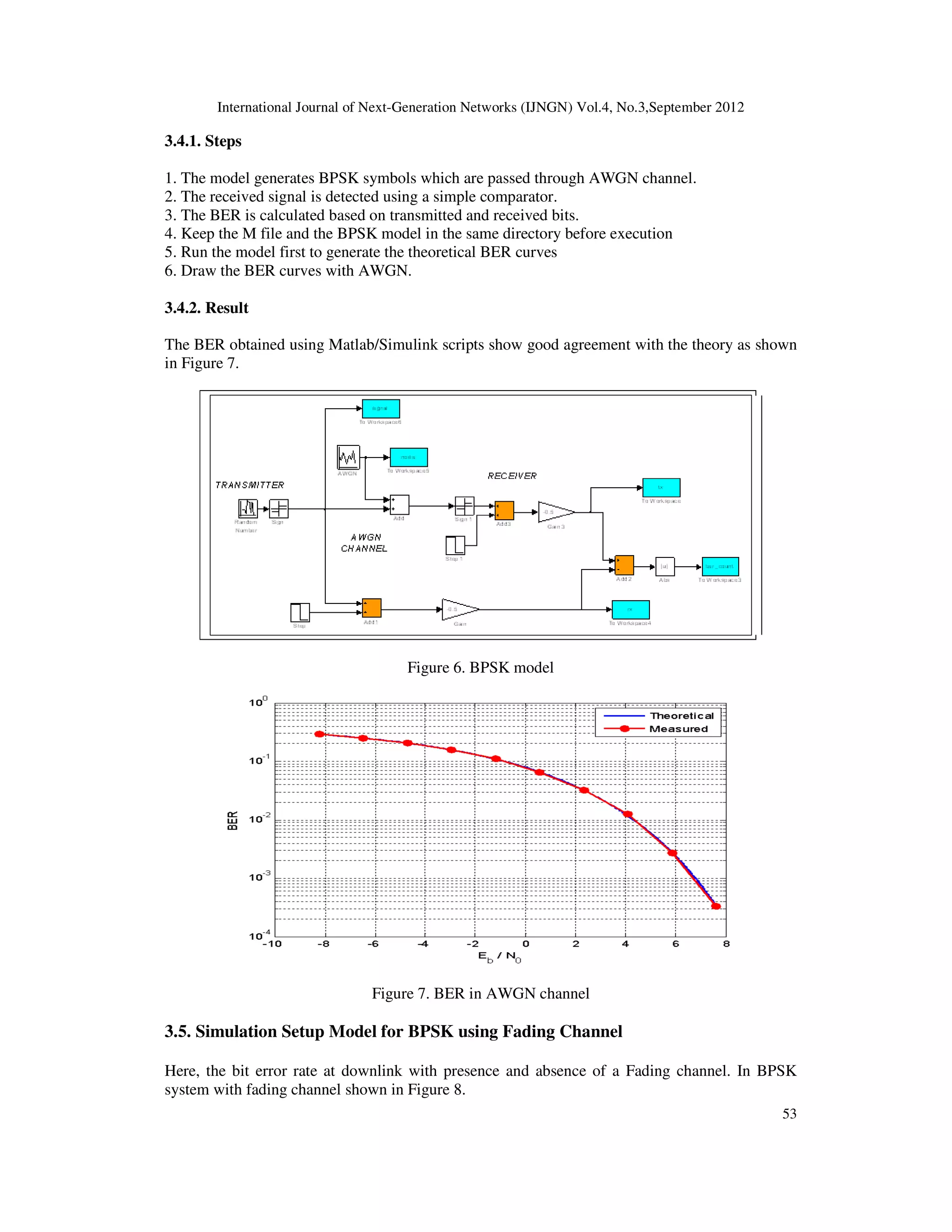
Ibrahim Aref
Computer Engineering Department, University of Tripoli, Tripoli, Libya
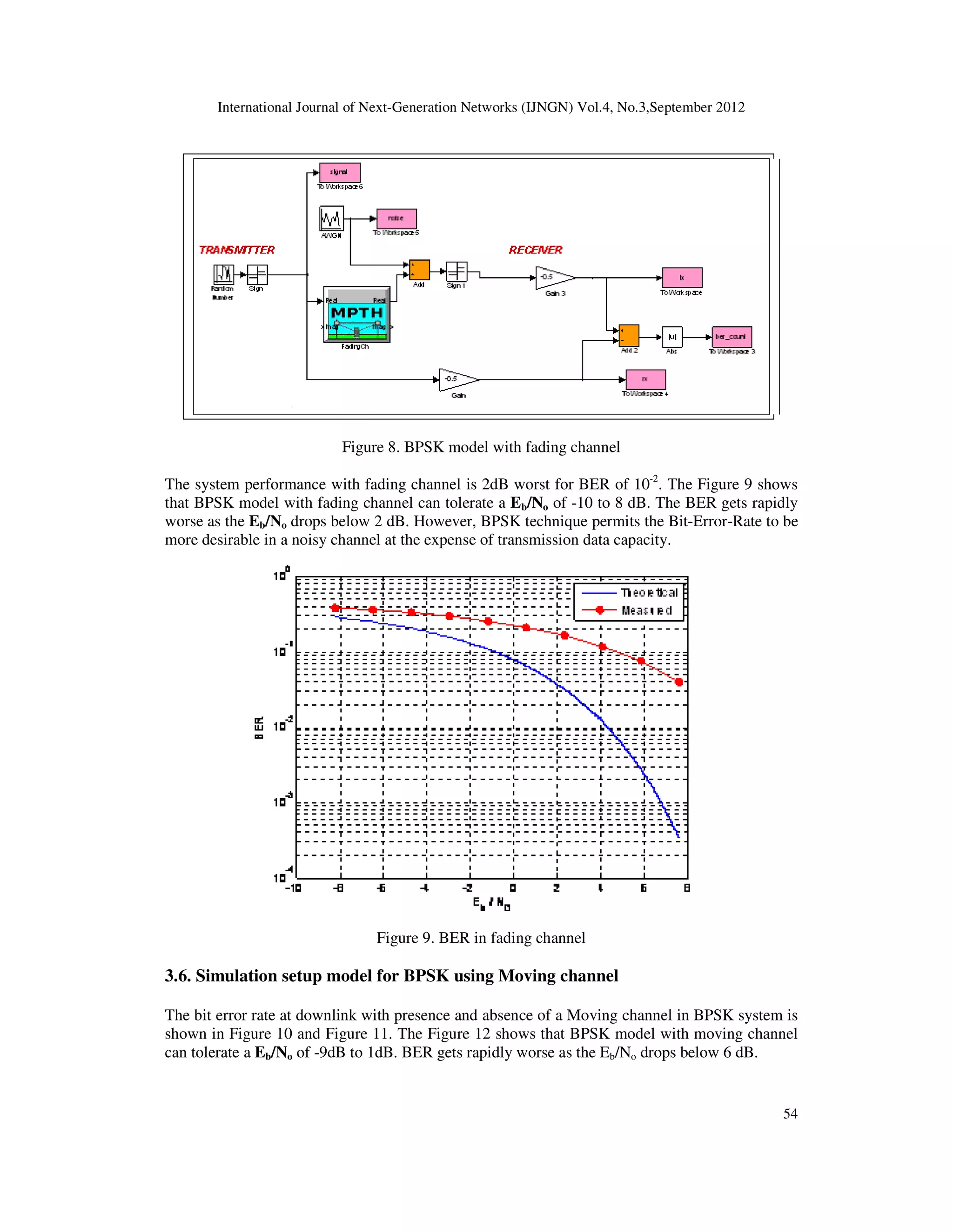
iaref@tripoliuniv.edu.ly
ABSTRACT
In this paper, the main aim is to design and simulate UTRA FDD control channel in the presence of noise
and wireless channel by using FDD library/Matlab box set that can be used to design and implement some
systems. Moreover, a test and verification of the library is achieved with different channel models such as
Additive White Gaussian Noise (AWGN), fading and moving channel models. FDD library are employed to
design whole transmitter and receiver. Then we had tested AWGN channel and some other channel models.
Also we illustrated what are control channels DCCH and the other one as understanding the whole system.
Moreover, the standards have been covered as well as implemented the whole transmit and receive chain
plus the generation of DPCH, DPCCH channel. we had tested the performance against the AWGN noise.
Then we have studied different channel models that are defined in the standard, used the few of them like
the fading channel and moving channel. We have tried to compare the performance in terms of Monte
Carlo simulation by producing the BER curves. We have also change some channel parameters like phase,
number of multipaths and we have tried to see the performance of the model in the presence of actual
channel model.
KEYWORDS
Modelling, Simulation, UTRA, FDD, Channel
1. INTRODUCTION
The cellular wireless communications industry has been one of the fastest growing technologies
in the past decade. Up to now, there are over four billion wireless subscribers worldwide. From
first generation (1G) till third generation (3G), the communication systems performance is
improved with the appearance of new technologies. At the present time, wireless communication
becomes a very important technology and has appeared in the market since it provides a set of
good features to the network users such as network mobility, scalability and connectivity.
Wireless networks are completely different from wired networks. In wired networks the signal
propagates through fixed time invariant medium such as cables, fibre optics etc. In case of
wireless communication the signal propagates through time varying channel i.e. the characteristic
of the propagation medium changes due to user mobility and terrain conditions. In the cellular
communication system, a large number of transmitters but with low power value are employed to
form cells. The cell represents the small geographic service region of the cellular system. The
basic and main requirement of the cellular system is the high capacity that can be performed by
confining the coverage of the all stations (base stations) to the cell size [1]. This is different from
traditional radio transmitter which would cover the entire city and whole city was one cell. So in](https://image.slidesharecdn.com/1-180315095015/75/INVESTIGATION-OF-UTRA-FDD-DATA-AND-CONTROL-CHANNELS-IN-THE-PRESENCE-OF-NOISE-AND-STANDARD-DEFINED-CHANNEL-MODELS-1-2048.jpg)
![International Journal of Next-Generation Networks (IJNGN) Vol.4, No.3,September 2012
46
order to achieve higher capacity that is to support a large number of user, the city must be divided
into a smaller cells and each cell must have a transmitter tower called base station (BS). The
customer can move around the cells regions (to go from one cell location to another), and then the
call will not be interrupted, because it is enabled by a switching techniques called hand-off [1, 2].
In this work, the focus will be on cellular mobile communications that introduced around 1980
based on the radio system technology and known as cell phones. At that time, the first generation
(1G) of wireless communications systems are presented and supported voice communications
with limited roaming [2]. A set of wireless standard introduced such as Advanced Mobile Phone
System (AMPS) [3]. AMPS is a 1G analogue mobile phone system standard that is expanded and
improved by Bell Labs and introduced in America in 1983, with differing such as Total Access
Communication System (TACS) available in Europe and Japanese Total Access Communication
(JTAC) available in Japan [4]. Most of these standards are based on frequency division
multiplexing (FDM) scheme which allocate each mobile user with different carrier frequency. In
FDM, data from different transmitters are sent at the same time but over multiple frequencies.
Each one of the sub-carriers frequencies is modulated by different data stream. In order to avoid
adjacent channel interference, there is a guard band between sub-carriers [5]. The main aim of
this work is to understand and simulate UTRA FDD control channel in the presence of noise and
wireless channel.
This paper is organised in four sections. In section one, an introduction and an overview of the 3G
technologies. Section two gives an idea about UTRA FDD Physical Layer. The simulation
models of FDD and results are illustrated in section three. Finally, conclusions are presented in
section four.
2. UTRA FDD PHYSICAL LAYER
3GPP introduced the first release of universal terrestrial radio access (UTRA) FDD air interface
in 1999. The UTRA radio access is based on wideband code division multiple access (WCDMA)
and hybrid time-division (TDCDMA). This release is specified with two antenna open-loop and
closed-loop transmits diversity modes. In this section, we will cover the UTRA physical layer [6].
2.1. UTRA Physical Layer
UTRA physical layer offer two ways of the implementations. The first one can be achieved by
using FDD and the other one by using TDD. Each approach satisfies different needs and
requirements. Briefly in this section, we will give an overview for each one.
2.1.1. FDD
FDD specifies two frequency bands that can be used for uplink and downlink. So its main
advantage is to be able to send and receive at the same time. Moreover, the cell size is not
depended by propagation delays because FDD didn't have a guard periods and time slots. Also for
this reason the timing synchronisation between base station and mobiles users less critical than
TDD. In other hand, FDD is more complicated that TDD because FDD radio units require
duplexers that can be employed to separate the incoming and outgoing signals at the antenna and
then FDD can send and receive at the same time [7]. Duplexers are created of filters, so this is the
reason to increase complexity and hardware components cost. Moreover, there is a disadvantage
which is the bandwidth couldn't be allocated in efficient way, because there is some service types
required more throughput on the downlink such as Internet access and other service required
more throughput on the uplink. Of course, it may possible to use just the required data rate by
adjusting the spreading factor, but it is still impossible to trade uplink BW for downlink BW [8].](https://image.slidesharecdn.com/1-180315095015/75/INVESTIGATION-OF-UTRA-FDD-DATA-AND-CONTROL-CHANNELS-IN-THE-PRESENCE-OF-NOISE-AND-STANDARD-DEFINED-CHANNEL-MODELS-2-2048.jpg)
![International Journal of Next-Generation Networks (IJNGN) Vol.4, No.3,September 2012
47
2.1.2. TDD
TDD is the Time Division Duplex mode. Here downlink and uplink employ the same frequency
band but they used different time slots. The time that specified for Dl or UL is divided into frames
and also each frame is divided into a group short durations known as time slot. All the time slots
could be allocated to DL or to the UL. So for the link that needs more throughputs, TDD allocates
more time slots for this link. Here the big advantage is the duplexer is not required, which means
that TDD becomes less complexity that TDD. But in the other side, TDD needs more
synchronization between its terminals that FDD that is based on time division concept (the base
station doesn't have the capabilities to send data at the same time as the mobile) [8].
2.2. UTRA Framework
In wideband code division multiple access, narrowband user data is distributed over a wide
bandwidth. This can be achieved by modulating user data sequence through very slow rate with a
channelization code in high rate. The spreading codes range starting from 4 up to 512 chips. In
case of uplink, the maximum number of chips (code length) is 256 chips. The rate of transferring
chips (rate of the chip) is 3.84 Mcps (Mega chips per second). This can be covered a bandwidth
of 5 MHz. Moreover, both Variable spreading factors and multi-code transmission can be
employed to support different data rates [6].
Length 38400 chips from scrambling codes are used on top of channelization codes. In the
downlink, the channelization code is employed to divide various intra-cell users. This separation
is based on various scrambling codes. On the other hand (uplink), the scrambling codes separate
different users. Also, channelization codes divide various physical data and control channels of a
user. This variation in the case of downlink and uplink is necessary:
• The orthogonal channelization codes number is restricted, os it makes a strict upper
bound to the achievable downlink capacity.
• In case of uplink, the restriction is not precise, because for example, a user can be used all
channelization codes and the scrambling codes set includes some million codes.
The data rates that can be supported by UTRA FDD basic mode is closed to 2.3 Mbps which
included both cases (uplink and downlink). In the downlink, the sending data with maximum rate
requires the employ of three parallel channelization codes and spreading factor equal 4, that
means, it assigns up to 75% of code resources to just a one user. In uplink case, sending data with
the peak rate is seen as a distortion or noise source in the communication network, but present
code of other intra-cell users are not changed.
2.2.1. UTRA FDD Downlink
The frame structure of the downlink channel is contained of 15 time slots; each with a length of
10 ms. Figure 1 shows a downlink frame structure of the physical channel. The radio frame
provides the following channels [6]:
1. Dedicated physical channel (DPCH): It is divided into dedicated physical data channel
(DPDCH) and dedicated physical control channel (DPCCH).
2. control channel : It contains the following :
• Transmit power control (TPC) bits that can be used for fast power control.
• Transport format combination indicator (TFCI) bits that used to tell the receiver
about transport channels states, which channel is active or not.](https://image.slidesharecdn.com/1-180315095015/75/INVESTIGATION-OF-UTRA-FDD-DATA-AND-CONTROL-CHANNELS-IN-THE-PRESENCE-OF-NOISE-AND-STANDARD-DEFINED-CHANNEL-MODELS-3-2048.jpg)
![International Journal of Next-Generation Networks (IJNGN) Vol.4, No.3,September 2012
48
• Pilot bits enabling the channel and signal to interference and noise ration (SINR)
estimation from DPCH.
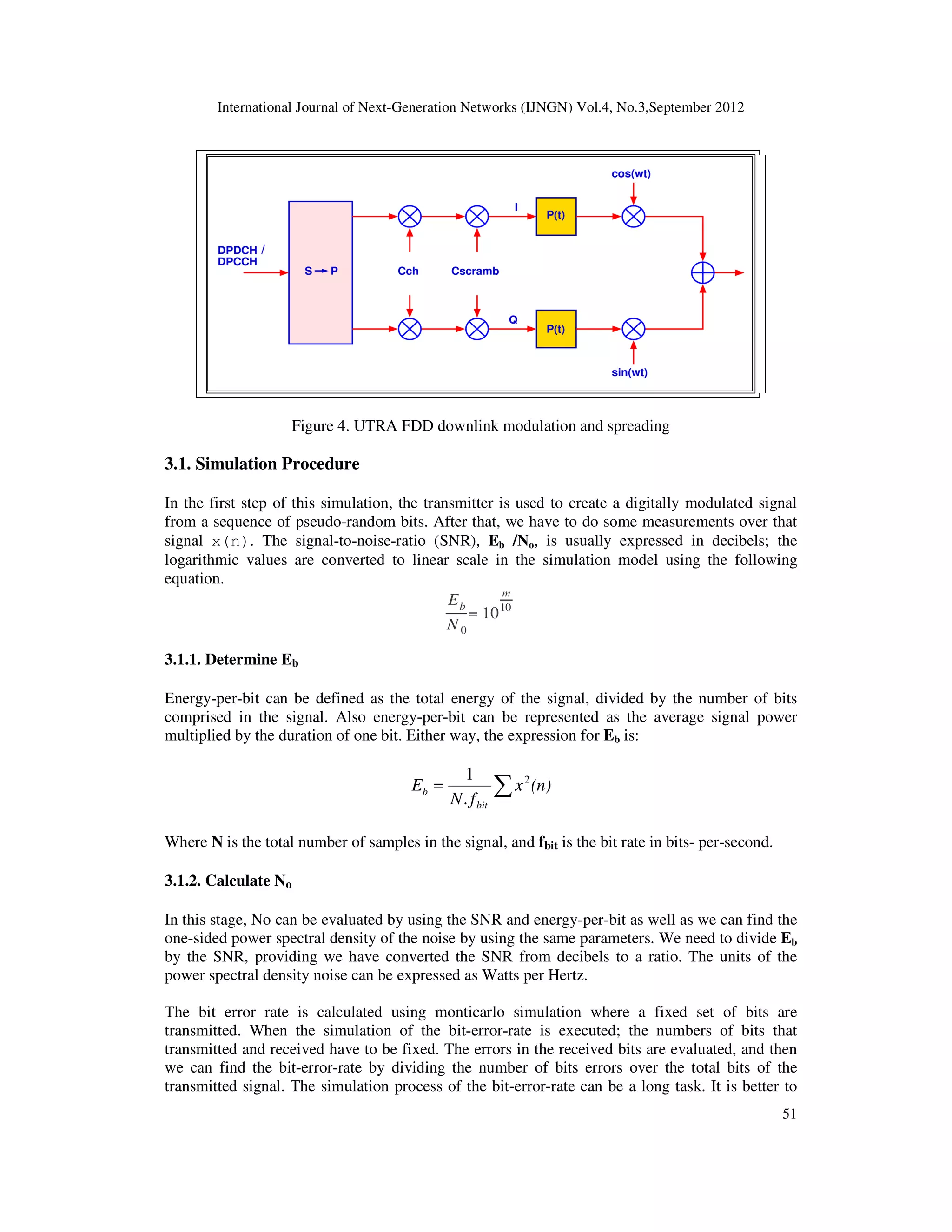
Figure 1. Downlink frame structure for dedicated physical channel
The primary common pilot channel (P-CPICH) and the secondary common pilot channel (S-
CPICH) are shown in Figure 1. The numbers in parentheses state that one sector in downlink
contain 1-2 parallel P-CPICHs and 0-15 parallel S-CPICHs.
Based on the specification of the UTRA FDD, there is just two P-CPICHs are ready to use at
maximum. Also multiple S-CPICHs can be presented, for example as beamforming purposes.
This presents a serious order compatibility problem in case of designing MIMO algorithms. If the
power in P-CPICH is constant (not subject to change) and it is distributed between two or more
transmit antennas, so the channel estimation in legacy mobile terminals is decayed. If the power
of P-CPICH is increased, interference to network increases as well [8, 9].
2.2.2. UTRA FDD Uplink
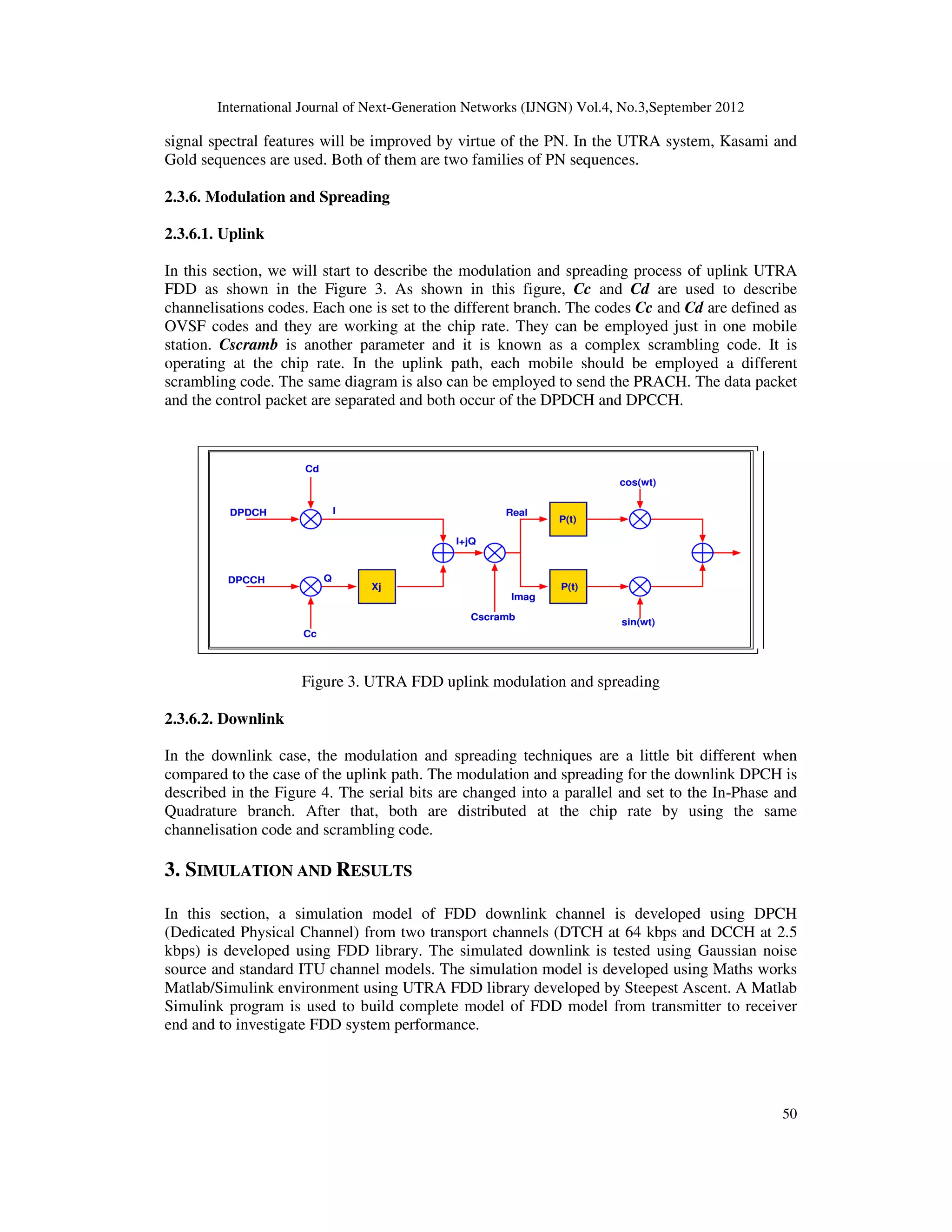
The uplink frame and time slot of the DPDCH and DPCCH are created as illustrated in the Figure
2. In the case of the uplink, control information and user data are constructed as I/Q code
multiplexed and some of DPDCHs could be integrated to a single DPCCH. Besides pilot bits, a
feedback information bits (FBI) are included with the TFCI and TPC uplink DPCCH slot. These
bits can be used to carry the state of the partial channel information. This can be done in case of
UTRA two-antenna closed-loop transmits diversity modes. In the uplink, only the user-specific
dedicated pilot channels are available in uplink. The users in the uplink are not synchronised.
Also the multi-user interference is not avoided, because user's channelization codes are non-
orthogonality[6,8].
2.3. UTRA FDD Physical Layer
2.3.1. Channels
The main function of the FDD Physical Layer is to transfer data and information to the other
protocol layers. This can be achieved by using channel. Here, there are two channels, the first one
is Transport Channels and the other one is Physical Channels.
1. Transport Channels are responsible to represent the characteristics of the data that will be
transmitted through the radio interface. The characteristics such as:](https://image.slidesharecdn.com/1-180315095015/75/INVESTIGATION-OF-UTRA-FDD-DATA-AND-CONTROL-CHANNELS-IN-THE-PRESENCE-OF-NOISE-AND-STANDARD-DEFINED-CHANNEL-MODELS-4-2048.jpg)
![International Journal of Next-Generation Networks (IJNGN) Vol.4, No.3,September 2012
49
• Format: Bit rate, encoding (convolution, turbo codes), interleaving.
• Framing / Multiplexing: This means how we can multiplex data if it created from
different sources (more than one).
• General Features: Power control features , collision possibility , Technique the used to
defined mobile station, Beam forming chance, Data rate changing , Broadcast region
(whole cell or just specific sector), Uplink or Downlink.
3. Physical Channel is responsible to describe the spectrum and code that employed by the
radio channel. Also in uplink case, it can state the relative phase, if it is In-Phase or
Quadrature.
Figure 2. Uplink frame structure for DPDCH/DPCCH
2.3.2. Transport Channels
Here we will state the channel types. Transport channels have two types. The first one is known
as Dedicated Transport Channels and the other one is known as Common Transport Channels.
2.3.3. Physical Channels
The physical channels are the representation of the transport channel, because we need to transmit
data through the air by using channel. In the uplink path, the physical channel is represented by
the following parameters [6]:
• Frequency, which means the carrier frequency.
• Channelisation code.
• Relative phase, if it is (0) means in-Phase or if it is (PI/2) which means Quadrature
component.
2.3.4. Channelisation Codes
In CDMA system, there are codes that can be employed in the channels separation process. These
channels may use a fixed frequency. It is important to select the suitable channelisation codes that
are orthogonal. So the system can support a different data rates and SF. UTRA employs
Orthogonal Variable Spreading Factor (OVSF) codes. There is a various values of the
channelisation codes. It is depended on the number of the physical channel and data rate. As
indicated in RTT manual, the voice channel number per carrier equal 250, which means,
orthogonal codes (256) take away some control channels.
2.3.5. Scrambling Codes
Scrambling operation is defined as spread chips multiple PN sequence. Using this operation, the](https://image.slidesharecdn.com/1-180315095015/75/INVESTIGATION-OF-UTRA-FDD-DATA-AND-CONTROL-CHANNELS-IN-THE-PRESENCE-OF-NOISE-AND-STANDARD-DEFINED-CHANNEL-MODELS-5-2048.jpg)
![International Journal of Next-Generation Networks (IJNGN) Vol.4, No.3,September 2012
62
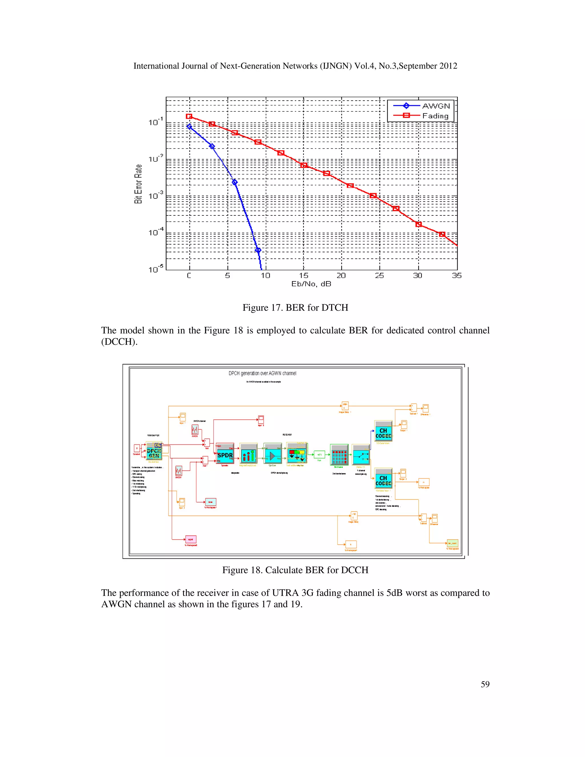
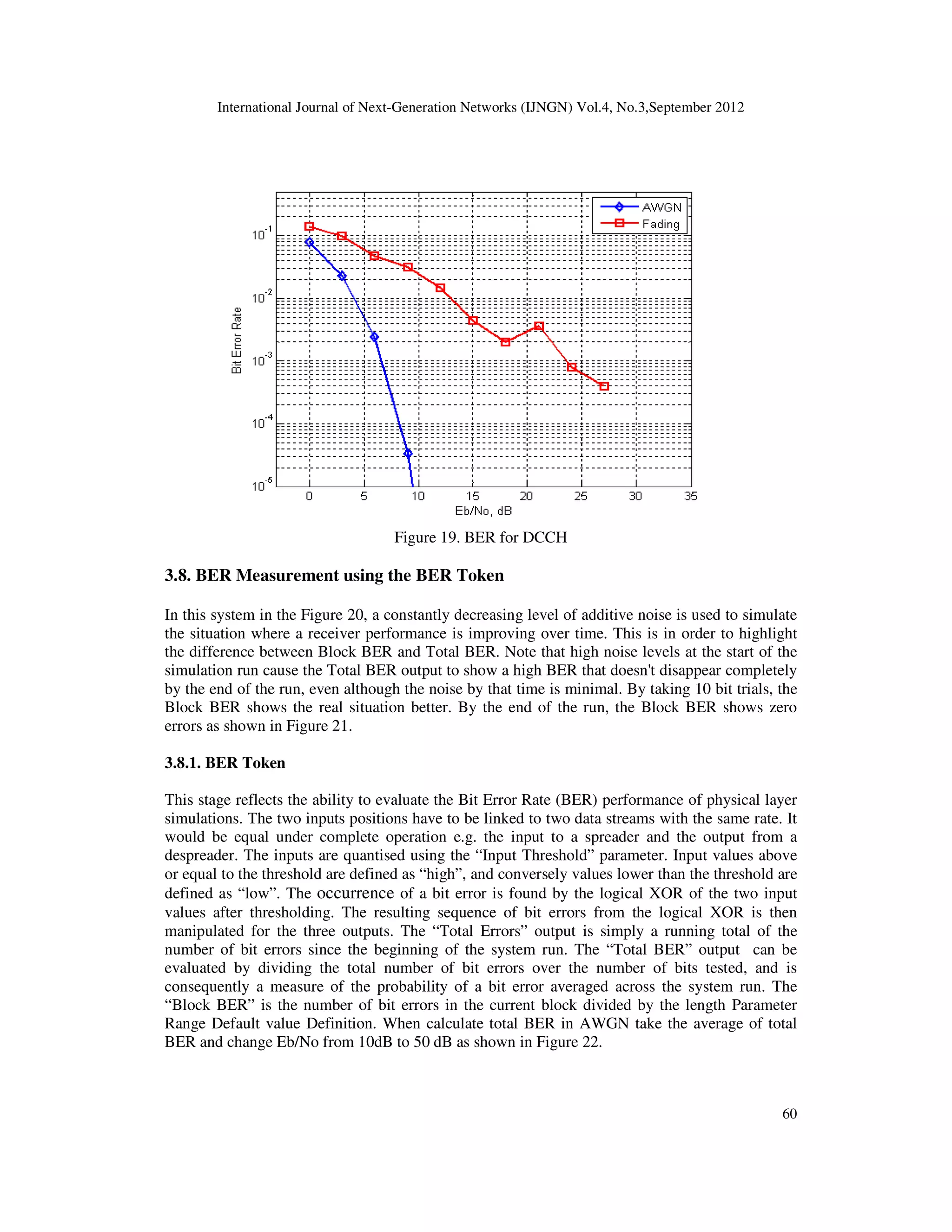
4. CONCLUSIONS
At the end of this work, we conclude that the benefits of using the FDD library for rapid
prototyping, system modelling and practical training have been presented. The performance of the
receiver in case of UTRA 3G fading channel is 5dB worst as compared to AWGN channel. The
performance gets worst with increasing number of multipaths and phase difference (between
different multipaths). Also the UTRA FDD library can be employed with many blocks from other
Simulink libraries, such as the DSP and Communications block sets, so that more complex,
proprietary models can be realised.
REFERENCES
[1] I. E. Consortium, Cellular communications, Web Proforum Tutorials - http://www.iec.org , 2004.
[2] G. Williams, Cellular communication networks, Lehigh Unversity , 1995.
[3] GeekInterview, What is 1g - rst generation, http://www.geekinterview.com ,2005.
[4] C. N. Perspectives, The amps family of wireless standards, http://www.cnp-wireless.com , 2007.
[5] F. Khan, LTE for 4G Mobile Broadband- Air Interface Technologies and Performance . rst ed., 2009.
[6] G. Tsoulos, MIMO System Technology for Wireless Communications . 2006.
[7] 4GWirelessEvolution, Nokia siemens networks demonstrates lte interoperability on qualcomm
platform, http://4g-wirelessevolution.tmcnet.com
[8] 3GPP, Third generation partnership project, http://www.3gpp.org , 2008.
[9] 3GPP, 3gpp ts 25.104 v3.5.0(2000-12), 3rd Generation Partnership Project, 2000.
Author: IBRAHIM AREF
ACADEMIC QUALIFICATIONS
• Doctor of Philosophy (PhD) in System Design and Modeling, Electronic and
Electrical Engineering, University of Glasgow, February 2011.
• Master of Science (MSc) in Computer Systems Engineering, University Putra
Malaysia (UPM), Faculty of Engineering, Computer and Communication Systems
Engineering Department, March 2004.
• B.Sc. in Computer Engineering, Al-Fateh University, Faculty of Engineering,
Computer Engineering Department, July 1993.
CURRENT POSITION
Lecturer in Computer Engineering Department, University of Tripoli-Libya.](https://image.slidesharecdn.com/1-180315095015/75/INVESTIGATION-OF-UTRA-FDD-DATA-AND-CONTROL-CHANNELS-IN-THE-PRESENCE-OF-NOISE-AND-STANDARD-DEFINED-CHANNEL-MODELS-18-2048.jpg)