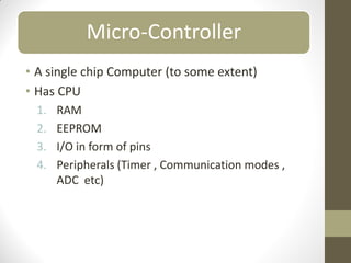
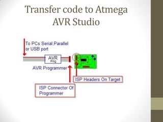
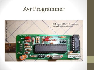
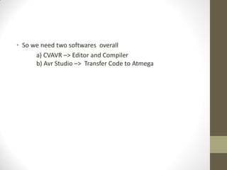
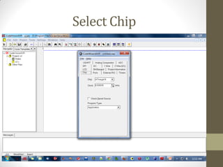
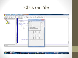
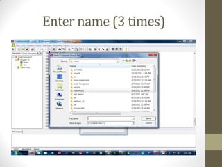
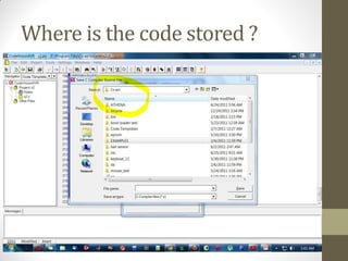
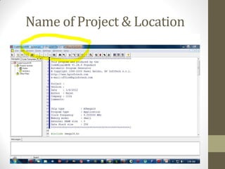
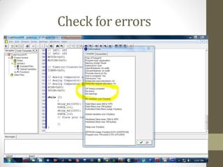
Introduction to
Microcontrollers
Rajat Arora
Micro-Controller
• A single chip Computer (to some extent)
• Has CPU
1. RAM
2. EEPROM
3. I/O in form of pins
4. Peripherals (Timer , Communication modes ,
ADC etc)
Flash Back (Takneek)
• Line Following Robots
• Wireless keyboards
• They were made using Microcontrollers
• Suppose we want to make a Line following Robot
• What do we do ?
• Use a computer with 2.4Ghz Intel core I7 with
4 Gb RAM , 500 Gb Hard disk , 1 Gb Graphics
Card ??
Why not a Computer ?
• PC is a general purpose computer.
• Can run thousand of softwares
• Microsoft ppt in which you are seeing this presentation
• Games (NFS , AOE , Call of Duty)
• Highly expensive
Why MCU
• Small reflected by the word “MICRO”
• Inexpensive
• Ideal for doing repetitive tasks
• Easy to use
• Highly Efficient and fast
Selecting a MCU
• Two family of MCU extremely popular
a) AVR
b) PIC
• We use AVR series of MCU from Atmel
• The instructions are fed once in the form of a Hex file
Tools Required -> CVAVR
Compiler -> CVAVR
• The code is written in C language so we need to convert it into
the format that Atmega understands
Transfer code to Atmega
AVR Studio
Avr Programmer
• So we need two softwares overall
a) CVAVR –> Editor and Compiler
b) Avr Studio –> Transfer Code to Atmega
Atmega 16
Basics of C language
• If else block
• If(condition)
{
… …
}
else
{
… …
}
While & For
• While (conditon)
{
… ...
}
• for(initialisation; condition; increment)
{
… …
}
•Lets Begin by blinking
a simple LED
Circuit Diagram
Getting Started with CVAVR
Open
CVAVR
Go to
File
New Project
Open CVAVR
Go to File
Click on New
Select Project- > Click OK
Click YES
Select Chip
Introduction
to I/O
• Atmega has total of 40 pins out of which 32 pins can be used
as Input or Output
• These 32 pins are divided into 4 groups of 8 pins
PORTA, PORTB , PORTC , PORTD
Data Direction register (DDR)
• This sets direction for all pins (32)
• Direction for these pins can be Input or Output
• To blink an LED we need to set pin as “OUTPUT” but “HOW“ ?
• DDRA = 0b00000001 ;
• DDRA = 0x01 ;
• 1 Stands for Output & 0 stands for Input
What Next ?
• We have set the Pin as Output
• What else do we need to light the LED ??
• Supply of 5 Volts !!! This is given by PORT Register
PORT Register
• Only after you have set the Pin to Output you can control
them through this Register
• It is a 8 bit register . It corresponds to the pin in same manner
as that of DDR Register
• Used to set output value ( 0 or 1 ) only if the corresponding
Pin has been set as output by DDR Register
• PORTA= 0b 00000001;
or
• PORTA= 0x01 ;
• 1 stands for 5V
• 0 stands for 0V
L L L L L L L H
MSB LSB
Simple Questions
• DDRA= 0b 00101100
• DDRD = 0xf4
• DDRC = 0b 01111110
• DDRB = 0x3b
Assume all 32 pins set as output
• PORTA = 0b00001100;
• PORTD = 0b11110000;
• PORTB.4=1;
• PORTC.2=1;
Setting I/O
Go to Ports
• Click on In to make that pin Output
• Can do so for all four ports
Click on File
Generate Save and Exit
Enter name (3 times)
Where is the code stored ?
Then Click Save
Name of Project & Location
Writing the Code
• NOTE : We write our code in While block
• While (1)
{
PORTA.1=1; // sets the Pin to 5 volts
PORTA.1=0; // sets the Pin to 0 volts
}
• This makes the LED to blink but we cannot see blinking !!!
• This is because Atmega runs at a frequency of 8000000 Hz
• We need to introduce delay so as to see blinking
• Use header file delay.h
• Function to be used  delay_ms(time in millis);
While (1)
{
delay_ms(1000);
PORTA.1=1;
delay_ms(1000);
PORTA.1=0;
}
How to compile
• Code is written in C language but Atmega understands
Hex file
so we need to convert the C file to Hex file
Compiling
Make the Project
Check for errors
Hex File
• You can find the Hex file in Bin folder or the EXE folder
of the directory where You installed CVAVR
• So we Have our Code ready
• Feed this code to Atmega using Programmer (we will see this
in workshop )
• Lets see the code in action
Lets add an Input
• Most Common Input  Button
• Since we have already made A0 as Input we connect a
button to that pin
• If button is pressed light the LED else turn it off
• First draw the Circuit Diagram
Circuit Diagram
• Never leave any Input pin unconnected / floating
at any point of time while your circuit is working
• In Last Circuit A0 is floating when button is not pressed
so our Circuit Diagram is wrong
• What is the Voltage at the Floating PIN ?
• Not 5 V
• Not 0V
• Its UNDEFINED
• So never leave an input pin unconnected
• Use the Concept of Pull up / Pull down
• In Layman terms
• PULL DOWN : Gives 0V when unconnected
• PULL UP : Gives 5V when unconnected
• Connect the PIN to Ground through a resistance for pulling
down
• Connect the PIN to 5V through a resistance for Pulling up
Correct Circuit Diagram
PIN Register
• It is a 8 bit register . It corresponds to the pin in same manner
as that of DDR Register
• It is used to read voltage at a pin
• To be used only after the pin has been set as input by DDR
register
Using Pin Register
int a; // Define the variable a to store the value of voltage
a=PINA.0; // read value at pin A.0 (make sure it is input)
If (a==1) // if voltage is 5V
{
PORTA.1=1; // Light the LED
}
else
{
PORTA.1=0; // Turn off the LED
}
Code in Action
Thank You

intro_mcu.pdf

  • 1.
  • 2.
    Micro-Controller • A singlechip Computer (to some extent) • Has CPU 1. RAM 2. EEPROM 3. I/O in form of pins 4. Peripherals (Timer , Communication modes , ADC etc)
  • 3.
    Flash Back (Takneek) •Line Following Robots • Wireless keyboards • They were made using Microcontrollers
  • 4.
    • Suppose wewant to make a Line following Robot • What do we do ? • Use a computer with 2.4Ghz Intel core I7 with 4 Gb RAM , 500 Gb Hard disk , 1 Gb Graphics Card ??
  • 5.
    Why not aComputer ? • PC is a general purpose computer. • Can run thousand of softwares • Microsoft ppt in which you are seeing this presentation • Games (NFS , AOE , Call of Duty) • Highly expensive
  • 6.
    Why MCU • Smallreflected by the word “MICRO” • Inexpensive • Ideal for doing repetitive tasks • Easy to use • Highly Efficient and fast
  • 7.
    Selecting a MCU •Two family of MCU extremely popular a) AVR b) PIC • We use AVR series of MCU from Atmel • The instructions are fed once in the form of a Hex file
  • 8.
  • 9.
    Compiler -> CVAVR •The code is written in C language so we need to convert it into the format that Atmega understands
  • 10.
    Transfer code toAtmega AVR Studio
  • 11.
  • 12.
    • So weneed two softwares overall a) CVAVR –> Editor and Compiler b) Avr Studio –> Transfer Code to Atmega
  • 13.
  • 14.
    Basics of Clanguage • If else block • If(condition) { … … } else { … … }
  • 15.
    While & For •While (conditon) { … ... } • for(initialisation; condition; increment) { … … }
  • 17.
    •Lets Begin byblinking a simple LED
  • 18.
  • 19.
  • 20.
  • 21.
  • 22.
  • 23.
  • 24.
  • 25.
  • 26.
  • 27.
  • 28.
    • Atmega hastotal of 40 pins out of which 32 pins can be used as Input or Output • These 32 pins are divided into 4 groups of 8 pins PORTA, PORTB , PORTC , PORTD
  • 29.
    Data Direction register(DDR) • This sets direction for all pins (32) • Direction for these pins can be Input or Output • To blink an LED we need to set pin as “OUTPUT” but “HOW“ ? • DDRA = 0b00000001 ; • DDRA = 0x01 ; • 1 Stands for Output & 0 stands for Input
  • 31.
    What Next ? •We have set the Pin as Output • What else do we need to light the LED ?? • Supply of 5 Volts !!! This is given by PORT Register
  • 32.
    PORT Register • Onlyafter you have set the Pin to Output you can control them through this Register • It is a 8 bit register . It corresponds to the pin in same manner as that of DDR Register • Used to set output value ( 0 or 1 ) only if the corresponding Pin has been set as output by DDR Register • PORTA= 0b 00000001; or • PORTA= 0x01 ; • 1 stands for 5V • 0 stands for 0V L L L L L L L H MSB LSB
  • 33.
    Simple Questions • DDRA=0b 00101100 • DDRD = 0xf4 • DDRC = 0b 01111110 • DDRB = 0x3b Assume all 32 pins set as output • PORTA = 0b00001100; • PORTD = 0b11110000; • PORTB.4=1; • PORTC.2=1;
  • 34.
  • 35.
  • 36.
    • Click onIn to make that pin Output • Can do so for all four ports
  • 37.
  • 38.
  • 39.
  • 40.
    Where is thecode stored ?
  • 41.
  • 42.
    Name of Project& Location
  • 43.
  • 44.
    • NOTE :We write our code in While block • While (1) { PORTA.1=1; // sets the Pin to 5 volts PORTA.1=0; // sets the Pin to 0 volts } • This makes the LED to blink but we cannot see blinking !!!
  • 45.
    • This isbecause Atmega runs at a frequency of 8000000 Hz • We need to introduce delay so as to see blinking • Use header file delay.h • Function to be used  delay_ms(time in millis); While (1) { delay_ms(1000); PORTA.1=1; delay_ms(1000); PORTA.1=0; }
  • 46.
    How to compile •Code is written in C language but Atmega understands Hex file so we need to convert the C file to Hex file
  • 47.
  • 48.
  • 49.
  • 50.
    Hex File • Youcan find the Hex file in Bin folder or the EXE folder of the directory where You installed CVAVR
  • 51.
    • So weHave our Code ready • Feed this code to Atmega using Programmer (we will see this in workshop ) • Lets see the code in action
  • 53.
    Lets add anInput • Most Common Input  Button • Since we have already made A0 as Input we connect a button to that pin • If button is pressed light the LED else turn it off • First draw the Circuit Diagram
  • 54.
  • 55.
    • Never leaveany Input pin unconnected / floating at any point of time while your circuit is working • In Last Circuit A0 is floating when button is not pressed so our Circuit Diagram is wrong
  • 56.
    • What isthe Voltage at the Floating PIN ? • Not 5 V • Not 0V • Its UNDEFINED • So never leave an input pin unconnected • Use the Concept of Pull up / Pull down
  • 57.
    • In Laymanterms • PULL DOWN : Gives 0V when unconnected • PULL UP : Gives 5V when unconnected • Connect the PIN to Ground through a resistance for pulling down • Connect the PIN to 5V through a resistance for Pulling up
  • 58.
  • 59.
    PIN Register • Itis a 8 bit register . It corresponds to the pin in same manner as that of DDR Register • It is used to read voltage at a pin • To be used only after the pin has been set as input by DDR register
  • 60.
    Using Pin Register inta; // Define the variable a to store the value of voltage a=PINA.0; // read value at pin A.0 (make sure it is input) If (a==1) // if voltage is 5V { PORTA.1=1; // Light the LED } else { PORTA.1=0; // Turn off the LED }
  • 61.
  • 62.