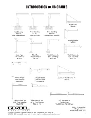
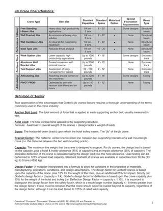
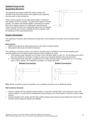
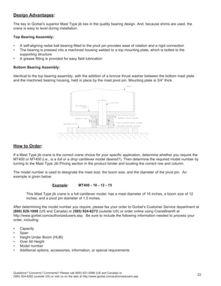
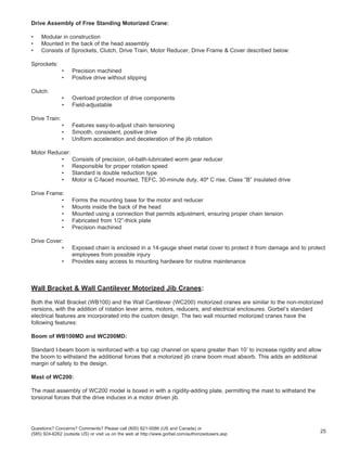
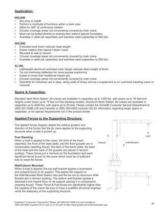
SlideShare a Scribd company logo
1 of 36
Download to read offline
INTRODUCTION to JIB CRANES
Free Standing
FS300
Base Plate Mounted
Free Standing
FS350
Insert Mounted
Free Standing
FS350S
Sleeve Insert Mounted
Questions? Concerns? Comments? Please call (800) 821-0086 (US and Canada) or
(585) 924-6262 (outside US) or visit us on the web at http://www.gorbel.com/authorizedusers.asp
1
© 2012 by Gorbel, Inc.
All rights reserved.
Printed in the U.S.A. 1/12
Wall Bracket
WB100
Wall Cantilever
WC200
Mast Type
Full Cantilever
MT400
Mast Type
Drop Cantilever
MT450
Tool Solutions Jib
Wall Mounted
TSJ50-WM & TSJ150-WM
Tool Solutions Jib
50 lb. Free Standing
TSJ50-FS
Tool Solutions Jib
150 lb. Free Standing
TSJ150-FS
U.S.A.
GORBEL INC.
Aluminum Wall Bracket Jib
AL100
Work Station Jib
Free Standing
WSJ360
Work Station Jib
Wall Mounted
WSJ200
PIVOT PRO®
Free Standing
PPRO-FS
PIVOT PRO®
Wall Mounted
PPRO-WM
Description:
Jib cranes are not created equally. Gorbel offers the most comprehensive features and design criteria in the
industry.
Properly applied Gorbel® jib cranes:
• Cover circular (or semi-circular) work areas
• Are versatile enough to perform a wide variety of local handling and spotting functions
• Are economical enough to be dedicated to individual work stations
• Can increase worker satisfaction and encourage safe work practices
• Provide a rapid return on investment
• Can be a useful addition to an overhead handling system, providing coverage in areas not efficiently serviced by
a main crane
• Can relieve a main crane of many handling operations where the greater capacity and energy consumption of
the larger unit would be wasted
• Can be effectively applied in the absence of a main crane, especially where load handling is localized
• Are an economical choice for outdoor installations
Gorbel manufactures three basic categories of jib cranes:
1. I-beam jib cranes (models FS300, FS350, FS350S, WB100, WC200, MT400 & MT450)
2. Enclosed track jib cranes (models WSJ200, WSJ360, TSJ50 & TSJ150)
3. Articulating jib cranes (models AJ360-F, AJ360-C, AJ200 & PPRO)
Each category of crane possesses specific advantages and characteristics to cover all types of applications. All
of Gorbel’s cranes are designed for deflection, as well as for stress, which minimizes bounce, deflection, and the
effort required to move a trolley. Several manufacturers design only for stress. Gorbel’s standard, pre-engineered jib
cranes are available in capacities from 50 pounds (23 kg) to 5 tons (4536 kg); please consult Gorbel if higher
capacities or non-standard designs are required.
Applications:
The following are just a few of the infinite number of uses for a Gorbel® jib crane:
• In work cells to provide localized material handling
• To supplement a large overhead crane system
• Where overhead cranes are not possible (due to lack of adequate building supports, etc.)
• To transfer materials from one work cell to another
• For suspension of tools
• For economical application outdoors
Warning: Equipment described herein is not designed for, and should not be used for, lifting, supporting, or
transporting humans. Failure to comply with any one of the limitations noted herein can result in serious bodily
injury, death, and/or property damage.
Considerations for Selecting a Jib Crane:
A careful analysis must be performed to determine how the crane will affect the efficiency of the work area and how
it will be used in daily operation. The following are the most important considerations when selecting a crane:
• The type and extent of the structural support available
• Current and anticipated requirements for powered operation of the hoist or crane
• The characteristics and design of each crane type
• The overall height and height under boom offered
• The relative cost of each jib crane type
• The overall cost of installation
Questions? Concerns? Comments? Please call (800) 821-0086 (US and Canada) or
(585) 924-6262 (outside US) or visit us on the web at http://www.gorbel.com/authorizedusers.asp
2
Jib Crane Characteristics:
Crane Type Best Use
Standard
Capacities
Standard
Spans
Motorized
Option
Special
Foundation
Requirements
Beam
Type
Performance
(I-Beam)
Free Standing
I-Beam Jibs
Heavy duty, high productivity
applications
1/4 ton -
5 tons
8’ - 20’ • Some designs Structural
beam
Wall Bracket Jibs An economical heavy duty
solution
1/4 ton -
5 tons
8’ - 30’ • None Structural
beam
Wall Cantilever Jibs An ideal jib for maximizing
headroom
1/4 ton -
5 tons
8’ - 20’ • None Structural
beam
Mast Type Jibs Reduced thrust and pull 1/4 ton -
5 tons
10’ - 20’ • None Structural
beam
Enclosed
Track
Work Station Jibs Lower capacity, high
productivity applications
Up to 1000
pounds
4’ - 16’ Some designs Enclosed
track
Aluminum Wall
Bracket Jibs
Easiest movement with
minimal bounce
Up to 2000
pounds
4’ - 20’ None Enclosed
track
Tool Support Jibs Suspension of tools,
management of cables
50 - 150
pounds
4’ - 12’ None Enclosed
track
Articulating
Articulating Jibs Reaching around corners or
into machines
Up to 2000
pounds
8’ - 16’ Some designs Tubing
PIVOT PRO® Optimized to pair with
vacuum tube lifters and air
hoists
Up to 150
pounds
8’ - 12’ None Tubing
Definition of Terms:
True appreciation of the advantages that Gorbel’s jib cranes feature requires a thorough understanding of the terms
commonly used in the crane industry:
Anchor Bolt Load: The total amount of force that is applied to each supporting anchor bolt; usually measured in
kips.
Axial Load: The total vertical force applied to the supporting structure.
Formula: Axial load = (overall weight of the crane) + (design factor x weight of load).
Boom: The horizontal beam (track) upon which the hoist trolley travels. The “jib” of the jib crane.
Bracket Center: The distance, center line to center line, between two supporting brackets of a wall mounted jib
crane (i.e. the distance between the two wall mounting points).
Capacity: The maximum live weight that the crane is designed to support. For jib cranes, the design load is based
on the capacity, plus a hoist & trolley allowance (15% of capacity) and an impact allowance (25% of capacity). The
allowable deflection of the crane is calculated using the design load plus the hoist allowance. Load testing can be
performed to 125% of rated load capacity. Standard Gorbel® jib cranes are available in capacities from 50 lbs (23
kg) to 5 tons (4536 kg).
Design Factor: A multiplier incorporated into a formula to allow for variations in the properties of materials,
manufacturing, operations, conditions, and design assumptions. The design factor for Gorbel® cranes is based
upon the capacity of the crane, plus 15% for the weight of the hoist, plus an additional 25% for impact. Simply put,
Gorbel’s design factor = (capacity x 1.4). Gorbel’s design factor for deflection is based upon the crane capacity plus
15% for the weight of the hoist and trolley (i.e. Deflection Design Factor = (capacity x 1.15)). It is important to
distinguish the design factor from the safety factor, which is a much larger number (typically 4 - 8 times greater than
the design factor). It also must be stressed that the crane should never be loaded beyond its capacity, regardless of
the design factor, although it can be load tested to 125% of rated load capacity.
Questions? Concerns? Comments? Please call (800) 821-0086 (US and Canada) or
(585) 924-6262 (outside US) or visit us on the web at http://www.gorbel.com/authorizedusers.asp
3
Deflection: The difference in elevation at the tip of the boom between an unloaded crane and a fully loaded crane;
usually measured in inches. Gorbel tends to have stricter deflection criteria than others in the industry. Typical
deflection of Gorbel® designs (where L = span of the crane in inches):
FS300, FS350, FS350S: L/150 (due to configuration restrictions some models may not meet these guidelines)
WC200, MT400, AJ360, AJ200, TSJ50, TSJ150, PPRO: L/150
WSJ360: L/200
WSJ200: L/320
WB100, AL100: L/450
Foundation: Many free standing jib cranes do not require a special foundation; they can be used with a standard
6-inch reinforced concrete floor. However, some jib cranes require a special foundation of concrete and steel, a few
feet wide and deep. Foundation recommendations can be found in the price pages and in the installation manual.
Height Under Boom (HUB): The distance from the floor to the underside of the crane’s boom. The minimum height
under boom equals the height of the load, plus the maximum distance the load is to be lifted, plus the headroom
required for the hoist, trolley, and attachments.
Kip: Kilopound. A unit of force equal to 1000 pounds (453.6 kg).
Mast: The vertical steel component of the jib crane which supports the crane. Free Standing jib cranes (including
Work Station Jibs, Pivot Pro®, Articulating Jibs and 150 lb. Tool Support Jibs) have a circular pipe for a mast, 50
lb. Tool Support jibs have a square pipe for a mast, Wall Cantilever cranes have standard I-beams, and Mast Type
cranes have wide flange beams. Wall Bracket cranes (including Work Station Jibs, Pivot Pro®, Articulating Jibs and
Tool Support Jibs) do not have a mast.
Overall Height: The distance to the highest point on the jib crane (should include hardware). A minimal clearance
(nominally 3 inches) is required from any obstructions above the boom or tie rod assembly throughout the entire
rotation of the crane.
Overturning Moment (OTM): The crane’s “moment” is the rotational force applied to the supporting structure,
created by hanging a load from the boom and the boom itself, causing a crane to want to tip over and the boom
deflect downward. The maximum moment occurs when the load is positioned furthest away from the mast or wall, at
the very tip of the cantilevered boom.
Portable Base: For smaller capacity jib cranes, digging up a floor for an adequate foundation is not always desired.
In many cases, a portable base/foundation is available. Please consult Gorbel for the product brochure regarding
portable bases.
Span: For a jib crane, span is the distance from the center of the pivot point to the end of the boom. Note that
“span” is greater than actual “working span” or “hook coverage”.
Supporting Structure: For a free standing jib crane (FS300, FS350, FS350S, WSJ360, AJ360-F, TSJ50-FS,
TSJ150-FS, PPRO-FS) the supporting structure is the foundation which the crane is bolted to or implanted in. For a
wall mounted jib crane (WB100, WC200, AL100, WSJ200, AJ200, TSJ50-WM, TSJ150-WM, PPRO-WM), the
supporting structure is the wall or column to which the crane is bolted. Mast type jib cranes (MT400, MT450) have a
supporting structure at both the ceiling and the floor. For a ceiling mounted articulating jib (AJ360-C) the supporting
structure is the overhead support the crane is mounted to.
Thrust & Pull: Forces exerted by a crane on its supporting structure. Thrust is the pushing (or compressive) force
exerted on the structure, while Pull is the tensile force. Thrust and Pull are thus equal (but opposite in direction) to
each other. The maximum thrust & pull occurs when the crane is loaded at full capacity.
Working Span: The working span (or hook coverage) is less than the span of the crane. It is a function of the
maximum hook reach and the ability to get the trolley close to the mast.
working span = (distance between trolley stops) - (hoist trolley length)
Questions? Concerns? Comments? Please call (800) 821-0086 (US and Canada) or
(585) 924-6262 (outside US) or visit us on the web at http://www.gorbel.com/authorizedusers.asp
4 Rev.
Painting and Special Finishes:
Gorbel offers several finishes to our cranes to suit all types of needs and environments. Some finishes may require
sandblasting.
With the STANDARD finish:
• A high pressure wand is used to spray and wash the entire piece
• One coat of self-priming paint is applied then the piece is ready for the baking process
• Structural (I-beam) jib cranes are painted yellow. Enclosed track and articulating jib cranes are painted blue
• Although we take great care in packing your crane systems for shipment, scratching or chipping of the paint may
occur in transit. This is not the responsibility of Gorbel
• At least one spray can of enamel paint is included with each crane order for field touch-ups. Additional touch-up
paint can be purchased through Gorbel
Several manufacturers currently match Gorbel’s standard colors (in different paint formulations) so that basic
touch-up paint can be purchased at a local hardware store, if desired:
			 Sherwin-Williams:				 Yellow: Gorbel Yellow
			 (both to be formulated in metal latex)		 Blue: Gorbel Blue
			 Dupont “Dulux” Semi-gloss:			 Yellow: F.S. 33434
			 DUP 4N31P					 Blue: F.S. 25102
			 Strathmore:					 Yellow: Y13-0030
		 (alkyd enamel)					 Blue: L13-0065
			 Valspar:					 Yellow: B289
		 (available as industrial enamel or epoxy) Blue: A58
Note: Air dry paint will typically have more gloss than our in-house baked paint.
The 304 Stainless Steel Work Station Jib Cranes are not painted, so that the food-grade, contamination-free quality
of the stainless steel system is maximized. Aluminum Wall Bracket Jib Cranes are not painted for this reason also.
Galvanizing is an alternate finish available from Gorbel. This process includes hot-dip zinc galvanizing performed
on the crane to increase corrosion resistance.
Sandblasting is another option commonly performed on Gorbel® cranes, especially if an epoxy or urethane paint is
to be used. Sandblasting is typically performed to SSPC-SP-10 or -6 (white or near white) specifications.
Customized paint colors and other finishing options are available upon request.
Additional costs and lead times for special finishes vary. Please contact a Gorbel® Customer Service Representative
at (800) 821-0086 (US and Canada) or (585) 924-6262 (outside US) for additional information.
Questions? Concerns? Comments? Please call (800) 821-0086 (US and Canada) or
(585) 924-6262 (outside US) or visit us on the web at http://www.gorbel.com/authorizedusers.asp
5
Quick Comparison Between Types of Gorbel® Jib Cranes:
The following is meant to provide you with a brief overview of the differences between the Free Standing Series
(FS300, FS350, FS350S), the Wall Bracket Series (WB100), the Wall Cantilever Series (WC200), the Mast Type
Series (MT400 & MT450), the Work Station Jib Series (WSJ360, WSJ200), the Articulating Series (AJ360-F,
AJ360-C, AJ200), the PIVOT PRO® Series (PPRO) and the Tool Support Jib Series (TSJ). This page does not
explain the full detail and advantages of each type; therefore, a thorough reading of each jib crane section is
strongly recommended.
Ability to be Relocated: The mast of the FS350 is permanently embedded into its foundation, and thus is not able
to be easily relocated after installation. The FS350S has only a permanently embedded sleeve. The other types of
jib cranes can be easily relocated, since they just bolt to their supporting structures.
Installation Costs & Time: The Free Standing Series and some Free Standing Work Station Jibs require a
steel-reinforced foundation with concrete pours, and thus typically have the most expensive installation costs and the
longest overall installation time. The FS350 and FS350S require two concrete pours.
Material Costs: The wall mounted tie rod jib cranes are typically the least expensive jib crane types, because they
require only a tie rod instead of a full mast for support. (Less steel = less cost.)
Maximum HUB: The Wall Cantilever, Free Standing, and Mast Type full cantilever jib cranes all offer a maximum
Height Under Boom. The Wall Bracket jib offers the least amount of HUB due to the location of its tie rod. (The tie
rod takes up significant space above the boom). Enclosed track and articulating jibs do not offer HUBs as great as
the structural jibs.
Thrust & Pull: Free Standing jibs exert force only on their foundation (floor), since they are not connected to any
other structure. The Mast Type jib exerts the least amount of thrust & pull on its structure compared to the wall
mounted jib cranes, since most of its forces are supported vertically by the mast. The wall mounted jibs exert very
significant thrust and pull forces on their supporting structures. Specific thrust & pull calculations can be found in the
pricing section for each crane type or in CraneBrain®.
Note: A qualified engineer or architect should be consulted to determine structural adequacy before
installation of any jib crane. Responsibility for determining if a structurally adequate wall, column,
or truss is available rests entirely on the customer.
Work Area Around the Mast: The FS350, FS350S, Mast Type and Tool Support Jib cranes offer maximum work
area space around the mast. The FS300, WSJ360, AJ360-F and Free Standing PIVOT PRO® have gussets around
their masts that may interfere with work area space (especially with larger capacities). The wall mounted cranes lack
a mast, but need to be mounted to a wall or column that may or may not interfere with the work area space.
Construction for Seismic Zones:
For those customers in seismic construction zones, the design criteria of cranes may change, depending on the
Zone Rating. Please contact Gorbel for seismic details.
Questions? Concerns? Comments? Please call (800) 821-0086 (US and Canada) or
(585) 924-6262 (outside US) or visit us on the web at http://www.gorbel.com/authorizedusers.asp
6
FREE STANDING JIB CRANES
Description:
• Available as Base Plate Mounted (FS300), Insert Mounted (FS350), and Sleeve Insert Mounted (FS350S)
• All three types use a similar mast pipe, head assembly, and I-beam boom
• Difference in the models is found in the mounting arrangement
• Provide for 360º of continuous rotation
• All models have a round mast pipe that remains stationary throughout rotation
FS300
Questions? Concerns? Comments? Please call (800) 821-0086 (US and Canada) or
(585) 924-6262 (outside US) or visit us on the web at http://www.gorbel.com/authorizedusers.asp
7
STANDARD BEAM DATA
Beam
Size
S6 @ 12.5#/ft.
W8 @ 18.4#/ft.
S10 @ 25.4#/ft.
S12 @ 31.8#/ft.
W16 @ 45#/ft.
W18 @ 50#/ft.
W21 @ 62#/ft.
W24 @ 84#/ft.
Flange
Size
3-3/8”
5-1/4”
4-5/8”
5”
7”
7-1/2”
8-1/4”
9”
Overall
Diameter
8”
12”
14”
16”
18”
20”
24”
30”
Wall
Thickness
1/4”
1/4”
3/8”
3/8”
3/8”
1/2”
1/2”
1/2”
Weight
per Foot
22.37#
33.4#
54.6#
62.6#
70.6#
104.1#
125.5#
158.0#
STANDARD MAST DATA
FS350 FS350S
FS300
(Base Plate Mounted):
• Mast is just bolted to the foundation, therefore can be easily relocated in the future
• Only one concrete pour is required
• A hexagonal base plate is welded to the base of the mast pipe, and is reinforced with six gusset plates equally
spaced around the circumference of the mast
• The base plate is secured via anchor bolts to a structurally adequate, reinforced foundation
• Utilizes full gussets in continual contact with the base plate. Other manufacturers typically utilize open gussets,
which can cause an undesirable, warped effect:
One of two bolt patterns is used for anchoring an FS300 jib crane: a six bolt pattern is utilized on cranes with a mast
diameter of 14” or less, and a twelve bolt pattern is used on cranes with a mast diameter of 16” or more:
FS350
(Insert Mounted):
• Mast is secured into the foundation (permanently embedded)
• Takes up no floor space around the mast (so it is suitable for installation where a base plate and gussets would
cause interference to the work area)
• Has a square base plate, 3” larger on all 4 sides than the mast diameter, welded to the mast
• Base is secured with anchor bolts to the first concrete pour, made below floor level
• The second pour, made to floor level, provides support for the mast pipe
• Usually the trickiest to install of the three types of FS cranes
FS350S
(Sleeve Insert Mounted):
• Mast of the FS350S is secured into the foundation via a sleeve
• Has no gussets or base plate to take up floor space, but, unlike the FS350, can be easily relocated at a later
date. (The sleeve, however, is permanently embedded in the foundation.)
• Permits easier leveling during installation than the FS350
• Sleeve is secured with anchor bolts to the first concrete pour, made below floor level
• Second pour, made to floor level, provides support for the sleeve and mast pipe
• Steel wedges are utilized in plumbing of the mast
Gorbel® Base Other’s Base
(exaggerated to show warped effect)
Six-Bolt Pattern Twelve-Bolt Pattern
Questions? Concerns? Comments? Please call (800) 821-0086 (US and Canada) or
(585) 924-6262 (outside US) or visit us on the web at http://www.gorbel.com/authorizedusers.asp
8
Application:
Free Standing series jib cranes:
• Are easy to install
• Perform a multitude of functions within a work area
• Allow for 360º of continuous rotation even when using electric- or air-powered hoists and trolleys
• Cantilever-style boom allows for maximum hoist lift
• Puts no stress on its building’s support structure (all the force of the crane is supported by its foundation).
FS series jibs are an ideal way to handle and transfer materials, and can be used to:
• Service an open area without being tied to a building structure
• Supplement a bridge crane
• Service an area where a bridge crane is not available or feasible
• Take the place of a wall or column mounted crane when less than 360º of rotation is sufficient, but no other
structure is available for support
Two key requirements must be met before selecting a Free Standing Series jib crane:
1. The jib crane, in all cases, must be supported by a structurally adequate foundation.
2. There must be sufficient clearance above the boom (nominally 3 inches) throughout its arc.
Spans & Capacities:
Standard (pre-engineered) Free Standing series jib cranes are available in 1/4-, 1/2-, 1-1/2, 1-, 2-, 3-, and 5-ton
capacities, with spans and heights under boom ranging from 8 to 20 feet. Please contact the Gorbel® Customer
Service Department at (800) 821-0086 for information regarding larger spans, capacities, or heights under boom, or
for special requirements not found in the product binder.
Note: Longer spans and heights under boom available through CraneBrain® on the web
Applied Forces to the
Supporting Structure:
The applied forces drawing details the relative position
and the direction of forces that an FS300 series jib crane
applies to the foundation that supports it.
When a load is applied to the crane, the front of the head
assembly, the front of the base plate, and the front
gussets are in compression (exerting thrust); the back
boom plate, the back of the head and the back of the
gussets are placed in tension (pulling).
These forces put a moment on the foundation and exert
significant thrust & pull on the crane, which must be of
sufficient size to resist the forces. Similar forces and moments are applied to models FS350 and FS350S.
Questions? Concerns? Comments? Please call (800) 821-0086 (US and Canada) or
(585) 924-6262 (outside US) or visit us on the web at http://www.gorbel.com/authorizedusers.asp
9
Design Advantages:
The features incorporated into the design of a Gorbel® Free Standing jib make it the most unique in the industry.
Head Assembly:
• Consists of two side plates, safety channel, back head plate, top head channel, upper front channel, weight
bearing frame assembly, front head channel, trunnion roller support bracket, and a trunnion roller kit
• Is joined with bolts to the boom, and transfers the boom loading directly to the top pivot bearing and the trunnion
roller assemblies
• Permits installation of the head prior to the boom
• Decreases the required installation clearances
• Allows for maximum hoist lift
• Permits in-head bottom entry electrification
• Utilizes a retaining pin to protect against dislodgment (this feature is exclusive to Gorbel)
• Large head size eliminates crushing of the trunnion rollers. Other manufacturers utilize a smaller head that can
disfigure and damage the crane components, leading to difficulty with the crane operation.
Retaining Pin:
• Increases safety by resisting dislodgment of the head
• Retaining pin is placed through the pivot pin above the weight bearing channel
• Is a feature exclusive to Gorbel
• Proven to be especially beneficial when a free standing jib is used in conjunction with an overhead crane. The
overhead crane’s hoist hook, if too low, can accidentally latch on to the jib’s boom and lift the assembly. Gorbel’s
design prevents against dislodgment if this situation arises.
Questions? Concerns? Comments? Please call (800) 821-0086 (US and Canada) or
(585) 924-6262 (outside US) or visit us on the web at http://www.gorbel.com/authorizedusers.asp
10
Top Pivot Bearing Assembly:
• Reduces the clearance needed for installation
• Allows for total enclosure of the bottom entry collector assembly within the head
• Connects the head assembly to the mast pipe
• Transfers the loading forces from the boom to the head and mast
• Incorporates a weight bearing channel connecting the two sides of the head assembly
• The weight-bearing channel supports a bearing housing that contains the outer face of a tapered roller bearing,
allowing for ease of rotation
Trunnion Roller Assembly:
• Unique design of the trunnion rollers (with tapered roller bearings and a large surface area) prevents cutting
into the mast, thus eliminating the need for a wear band. Other manufacturers utilize smaller trunnion rollers or
cams that may actually carve into the pipe during rotation
• Simplifies the leveling of the boom during installation and provides great ease of rotation
• Provides the second bearing point within the head assembly to transmit the moment exerted on the boom to the
mast pipe
• Trunnion roller is designed to rotate around the mast with full face contact
• Rotation is made possible via two roller bearings, held in the trunnion roller channel by a 1-inch bolt. Two types
of trunnion roller assemblies are utilized in the FS Series jib cranes:
		 Type 1: Free standing jib cranes with
			 a mast diameter of 16” or less
			 have a trunnion roller assembly
			 consisting of a single formed
			 channel and two rollers.
		 Type 2: With mast diameters of 18” or
			 more, four rollers are used.
Leveling of the boom is accomplished in one of two
ways:
		 Type 1: With mast diameters of 20” or less,
				 shims can be placed where the boom
				 meets the head assembly.
		 Type 2: With mast diameters of 24” or more,
				 the trunnion roller assembly can be
				 adjusted.
Questions? Concerns? Comments? Please call (800) 821-0086 (US and Canada) or
(585) 924-6262 (outside US) or visit us on the web at http://www.gorbel.com/authorizedusers.asp
11
TYPE 1
TYPE 2
Independent Boom:
• Allows the head assembly to be installed separately from the boom for easier handling
• Lowers installation costs
• Reduces required clearances
Collector Assemblies:
• Provides for 360º continuous rotation in instances where power is fed to the crane and full rotation is desired
• Available initially, or as a simple field modification
• Two types of collector assemblies are used on the FS Series jib cranes:
1. When power is fed from the ceiling, a top entry collector is utilized*.
2. When power is fed from below, a bottom entry collector is used.
*Note: An additional 11-1/2” clearance above the boom is required to install a top entry collector.
Bottom Entry Collector:
Top Entry Collector:
Questions? Concerns? Comments? Please call (800) 821-0086 (US and Canada) or
(585) 924-6262 (outside US) or visit us on the web at http://www.gorbel.com/authorizedusers.asp
12
How to Order a Free Standing Jib Crane:
We at Gorbel hope to make the ordering process as simple and convenient as possible for you. When ordering an
FS series jib crane, please include the following information:
• Mounting Style (i.e., base plate: FS300, insert mounted: FS350, or sleeve insert: FS350S)
• Capacity
• Span (pivot point to end of boom)
• Height Under Boom (HUB) or Over All Height (OAH)
• Model Number
• Desired Accessories (tagline, anchor bolts, plywood base plate template, bottom or top entry collector, etc.)
• Any other critical information (i.e., outdoor application, motorized rotation, etc.)
• Reference the quote if one was provided to you
An example is used below to help explain the model number, pricing, and ordering process:
		 Example: A customer needs a free standing, floor mounted jib crane with a 1-ton capacity,
				 15-foot span, and 10-foot height under boom.
		 First determine whether an FS300, FS350, or FS350S is required. In this case, an FS300 is required since
		 the crane is to be floor mounted with a base plate. Then, to specify and price such a crane, find the
		 appropriate model number by turning to the Free Standing Jib Pricing section in the product binder. On the
		 1-ton page, the span would be “15 feet”, and the Height Under Boom would be “10 feet”. Find the box
		 where these two columns intersect to get the model number (14-12), the weight in pounds, and the price.
		 The complete model number for this FS series jib crane would thus be:
			 FS300 - 14 - 12
		 Note: The middle number (mast diameter) of the FS series model designation (14” in this instance),
			 determines the other pertinent information about the crane, including bolt circle diameter, bolt
			 pattern, number of bolts, and the size of the bolts. The Installation & Maintenance Manual provides
			 this information, as well as foundation requirements and installation instructions. The size of the
			 I-beam (12” in this case) will help determine the trolley.
Please fax in your order to Gorbel’s Customer Service Department at (800) 828-1808 (US and Canada) or
(585) 924-6273 (outside US), with your order information or order online using CraneBrain® at
http://www.gorbel.com/authorizedusers.asp.
Questions? Concern? Comments? Please call (800) 821-0086 (US and Canada) or
(585) 924-6262 (outside US) or visit us on the web at http://www.gorbel.com/authorizedusers.asp
13
WALL BRACKET JIB CRANES
WB100
Description:
• Combines simplicity of design, heavy duty construction,
ease of installation, and low cost
• Places emphasis on ease of rotation and quality
• Consists of a standard I-Beam for the boom, a tie rod
(right-hand-threaded at each end), a top and a bottom
bracket, a beam bracket, and trolley stops
• Offers a wide variety of practical uses within its
approximate 200º rotational area
Application:
• Especially desirable for individual use in bays, along walls
of shops, and as a supplement to an overhead traveling crane or monorail
• Provides a versatile and cost-effective solution to crane needs where adequate headroom and structural support
exist
• Covers approximately 200º of rotation
• Is the most economical solution as compared to other jib cranes because the tie rod suspension eliminates the
need for a mast member, and permits the use of a smaller section boom than the cantilever-style suspensions of
other jib cranes (less steel = less cost)
Two key requirements must be met before selecting the Wall Bracket series jib crane:
1. There must be a structurally adequate wall, column, or truss to support the crane.
Note: Responsibility for determining if the support is adequate rests entirely on the customer.
				 Information on the loading of the support by the crane can be found in the WB100 pricing
				 section under the column labeled “Thrust & Pull.”
2. There must be sufficient clearance (nominally 3”) above the tie rod throughout its arc.
Spans & Capacities:
Standard (pre-engineered) Wall Bracket jib cranes are available in 1/2-, 1-, 2-, 3-, and 5-ton capacities, with
standard boom spans ranging from 8 to 30 feet. Please contact the Gorbel® Customer Service department at
(800) 821-0086 or (585) 924-6262 for information regarding larger spans and capacities, or for special requirements
not found in the product binder.
Applied Forces to the
Supporting Structure:
The applied forces diagram details the relative position and
direction of the forces that a Wall Bracket jib crane applies to the
structure that supports it when a load is picked up.
When a load is applied, the top wall bracket applies an overall
downward and outward force (pull) on its support. The tie rod is in
tension. The bottom wall bracket applies a downward and inward
force (thrust) on its support. These Thrust & Pull forces are
significantly higher than the capacity of the crane! Be sure to have
a qualified structural engineer verify the adequacy of the
supporting structure.
Questions? Concerns? Comments? Please call (800) 821-0086 (US and Canada) or
(585) 924-6262 (outside US) or visit us on the web at http://www.gorbel.com/authorizedusers.asp
14
Design Advantages:
The key to Gorbel’s superior Wall Bracket jib crane lies in the design and manufacture of the bracket system, and in
the fact that cap channels are added to longer spans for lateral stability.
Top Bracket Construction:
• Absorbs the pull of the tie rod while still maintaining great ease of rotation
• All bolted connections are in double shear
• The bracket does not rely on any tension welds
• The bronze bushing/thrust washer combination provides ease of rotation, long life, and low maintenance
requirements
• Resists drift once rotation has been stopped
• The top bracket consists of three parts:
1. A formed steel channel which is bolted to the supporting structure (mounting bolts not provided).
2. A clevis bracket, consisting of a steel tube with two bronze bushings pressed into it, and a wrap-around
channel. A grease fitting is provided for field lubrication. This clevis bracket rests on a bronze, oil-
impregnated thrust washer, and is retained in the formed wall channel by means of a pivot bolt
assembly in double shear. The thrust washer prevents a steel-on-steel situation, and eases rotation.
3. A formed rod clevis, attached to the top end of the tie rod with an adjusting nut and lock washer; and
retained in the clevis bracket by means of a bolt or pin in double shear.
Beam Bracket Construction:
• Connects tie rod to beam near end of span
• Consists of a formed clevis fastened to the tie rod, and bolted to the formed beam channel
• Design does not rely on any tension welds
• Pivot bolt is in double shear
Bottom Bracket Construction:
• Accepts the downward and compressive forces which the crane applies, yet provides optional ease of rotation
and resistance to drift for the boom
• Has a formed channel which bolts to the supporting structure
• Has two beam-connecting plates welded to a steel tube, which contains two bronze bushings
• The bolts connecting the plates to the beam are in double shear, with a minimum dependency on a weld to carry
the load
• The beam bracket assembly rests on an oil-impregnated bronze thrust washer and is held in the formed wall
channel by means of a pivot bolt assembly in double shear
• A grease fitting is provided for field lubrication
Questions? Concerns? Comments? Please call (800) 821-0086 (US and Canada) or
(585) 924-6262 (outside US) or visit us on the web at http://www.gorbel.com/authorizedusers.asp
15
Wall Channel (Formed Channel) Thickness:
		 WB-G1		 1/2”
		 WB-G2		 5/8”
		 WB-G3		 3/4”
		 WB-G5		 1.0”
Tie Rod:
• A single tie rod (ASTM A36), right-hand threaded at each end, is utilized
• Offers ease of leveling
• Assures that the bottom bracket and I-beam will be loaded evenly
• Design is superior to a double tie rod arrangement that depends on even adjustment of the two rods, which can
increase installation time and costs
How to Order:
If a Wall Bracket series jib crane is the right crane for your specific application, determine the model number
required and the list price by turning to the Wall Bracket Jib Pricing section in the product binder, and locating the
correct row and column. These charts also provide information regarding the bracket center dimensions, thrust
and pull exerted, and shipping weights for each standard crane model. The model number is used to designate the
bracket fitting size, the span, and the depth of the boom. An example is given below:
					 Example:		 WB100 - G2 - 16 - 10
In this example, the wall bracket jib crane has a “G2” size fitting, the span is 16 feet, and the depth of boom is 10
inches.
Please fax your order to Gorbel’s Customer Service department at (800) 828-1808 (US and Canada) or
(585) 924-6273 (outside US) or order online using CraneBrain® at http://www.gorbel.com/authorizedusers.asp.
Be sure to include the following information:
• Capacity
• Model number
• Span
• Bracket center distance
• Bracket fitting size
• Desired accessories
• Any additional critical information
Wall Bracket Fittings Kit:
Customers can make their own WB100 series jib crane by using Gorbel’s high-quality components. The customer
buys an I-beam locally, and is responsible for assembly.
• Kits are available for capacities up to 5 tons, for spans ranging from 8 to 30 feet
• Kit consists of a top wall bracket, a bottom wall bracket, and a beam bracket (these parts are the same as those
used for Gorbel’s standard WB100 jib cranes)
• A tie rod is used with the kit, and can be purchased either locally or from Gorbel (tie rod is not included in the
standard kit price)
An additional hardware kit is also available, and consists of the hardware required to connect the lower bracket and
the beam bracket to the I-beam, and the hex nuts and washers needed to attach the tie rod to the clevis assemblies.
Bracket center dimensions must be held to those given in the WB100 series chart. Gorbel is not responsible for
deviation from above capacity and span recommendation, variance from the recommended limitations between
brackets, overloading, or incorrect installation of crane.
Questions? Concerns? Comments? Please call (800) 821-0086 (US and Canada) or
(585) 924-6262 (outside US) or visit us on the web at http://www.gorbel.com/authorizedusers.asp
16
WALL CANTILEVER JIB CRANES
WC200
Description:
• Combines high quality, safety, stringent design criteria, ease of installation, and ease of rotation
• Consists of an I-Beam for the mast and boom, two fabricated rotating brackets that bolt to the structural support,
and trolley stops
• Mounts to a wall or column
• Provides approx. 200º of rotation
The WC200 series provides a versatile and cost-effective solutions to your crane needs. All fittings are made of
structural steel and are manufactured to avoid reliance upon castings. Mast/boom connections are designed for
maximum shipping economy and ease of installation.
Application:
• Similar in use to the wall bracket jib crane, but has the advantage of allowing maximum hoist lift
• Can be installed close to the underside of the lowest overhead obstruction (nominally a minimum of 3 inches)
• Especially desirable for individual use in bays, along walls, and sides of shops, or as a supplement to a traveling
overhead crane or monorail
Two key requirements must be met before selecting a Wall Cantilever series jib crane:
1. There must be a structurally adequate wall, column, or truss to support the crane.
			 Note: Responsibility for determining if the support is adequate rests entirely on the customer.
				 Information on the loading of the support by the crane can be found in the WC200 pricing
				 section under the column labeled “Thrust & Pull.”
2. There must be sufficient clearance above the boom (nominally a minimum of 3 inches) throughout its
arc.
Spans & Capacities:
The Wall Cantilever jib cranes are available in capacities up to 5 tons, with standard boom spans up to 30 feet.
Please contact the Gorbel® Customer Service Department at (800) 821-0086 (US and Canada) or (585) 924-6262
(outside US) for information regarding larger spans or capacities, or for special requirements not in the product
binder.
Questions? Concerns? Comments? Please call (800) 821-0086 (US and Canada) or
(585) 924-6262 (outside US) or visit us on the web at http://www.gorbel.com/authorizedusers.asp
17
Applied Forces to the
Supporting Structure:
The applied forces diagram details the relative position and
direction of the forces that this jib crane applies to the supporting
structure when a load is picked up.
When a load is applied, the top wall bracket applies a downward
and outward force on its support. This places the support in tension
(pulling). The bottom wall bracket applies a downward and inward
force on its support, placing it in compression (exerting thrust).
These Thrust & Pull forces are significantly higher than the capacity
of the crane! Be sure to have a qualified structural engineer verify
the adequacy of the supporting structure.
Design Advantages:
The superiority of Gorbel’s Wall Cantilever jib cranes lies in the mast/boom connection and the bracket system
design.
Mast & Boom:
• Stiffeners are placed at critical stress points in the mast for torsional rigidity
• Removable trolley stops are bolted to the boom
The mast/boom connection comes in two styles to maximize ease of installation and minimize shipping costs.
General guidelines are as follows (please note that some exceptions do exist):
1. If the bracket center dimension is 6-1/2 feet or less, the beam depth is under 18”, and the fitting size is B3 or
less, the mast/boom connection is made by using a top mast plate welded to the mast and boom.
2. If the bracket center dimension is greater than 6-1/2 feet, the beam depth is greater than 18”, or the fitting
size is a B5 or greater, the mast/boom connection is a bolted connection.
Note: Bolted connections may be requested in lieu of welded connections for an additional charge.
Wall Cantilever Brackets:
• Feature a design that has excellent torsional rigidity, a pivot bolt in double shear, and resistance to boom drift
• Ease of rotation is insured with oil-impregnated bronze bushings and a thrust-washer to prevent a steel-on-steel
situation
• Inherent strength of the I-shape and the large welding surface area of the butt weld between the mast and the
brackets adds exceptional strength and reliability
Questions? Concerns? Comments? Please call (800) 821-0086 (US and Canada) or
(585) 924-6262 (outside US) or visit us on the web at http://www.gorbel.com/authorizedusers.asp
18
Welded Connection Bolted Connection
The top and bottom brackets utilize identical fittings, each consisting of two parts:
1. A formed channel which is bolted to the structural support (mounting
bolts not provided).
2. A fabricated I-shaped bracket comprised of three plates, two of which
have a hole for a steel tube. The third plate forms the web of the “I” and
is welded to the other plates and the steel tube. Two bronze bushings
are pressed in each end of the tube, and a grease fitting is provided for
field lubrication. The bracket is butt welded to the back of the mast. The
I-shaped bracket rests on a thrust washer, and is held on the wall by a
pivot bolt assembly.
How to Order:
If the Wall Cantilever is the right crane for your specific application, determine the model number required by turning
to the Wall Cantilever Jib Pricing section in the product binder, and locating the correct row and column. The
pricing section also shows list price, bracket fitting size, bracket center dimensions, wall-to-bracket dimensions,
beam size, shipping weight, and thrust/pull information for standard cranes. Please contact the Gorbel® Customer
Service Department for additional information not found in the sales binder.
The Model Number is used to designate the bracket fitting size, the span, and the boom depth. An example is given
below:
				 Example: WC200 - B3 - 10 - 16
This Wall Cantilever jib crane has “B3” size brackets, a 10-foot span, and a boom depth of 16 inches.
After determining the required model number and list price, please fax your order to the Gorbel® Customer Service
department at (800) 828-1808 (US and Canada) or (585) 924-6273 (outside US) or order online using CraneBrain®
at http://www.gorbel.com/authorizedusers.asp.
Please include all of the following information:
• Capacity
• Model number
• Span
• Bracket fitting size
• Bracket center distance
• Beam depth
• Desired accessories or options
• Any additional information or special instructions
Wall Cantilever Fittings Kit:
Customers can make their own WC200 series jib crane by using Gorbel’s high-quality components. The customer
buys the I-beam mast and boom locally, and fabricates the mast stiffeners, top connection plate, corner brace, and
trolley stops.
• Kit consists of the top and bottom wall brackets and eight A325 bolts used to connect wall brackets to jib (by
others)
• Includes a formed mounting channel, pivot bolts with lock washer and hex nut, fabricated pivot assembly, and
thrust washer
• Standard kits are available for capacities up to 3 tons, for spans ranging from 8 ft. up to 20 ft.
Bracket center dimensions must be held to those given in the WC200 series chart. Gorbel is not responsible
for deviation from the listed capacity and span recommendations, variance between the recommended limitations
between brackets, overloading, or incorrect installation of crane.
Questions? Concerns? Comments? Please call (800) 821-0086 (US and Canada) or
(585) 924-6262 (outside US) or visit us on the web at http://www.gorbel.com/authorizedusers.asp
19
Wall Channel (Formed Channel) Thickness:
		 WC-B1		 1/2”
		 WC-B2		 5/8”
		 WC-B3		 3/4”
		 WC-B5		 1.0”
MAST TYPE JIB CRANES
Description:
The Mast Type Series Jib Crane:
• Consists of top and bottom bearing assemblies, a wide-flange mast, and an I-beam boom with removable trolley
stops
• Mast rotates along with the boom
• Exerts the least amount of force on its supporting structure of any jib crane series
• Is floor-supported and top-stabilized
• Capable of 360º rotation via a top and bottom bearing assembly
• Allows full utilization of the working area (providing there are no obstructions)
• Provides the most economical solution where maximum lift is required
• Special foundation preparation is typically not required
• Is frequently installed under a crane rail or near a wall, therefore not utilizing the full 360º of continuous rotation
• Many different types and shapes of support structures are adequate
There Are Two Styles of Mast Type Jibs:
MT400 - Full cantilever model
• Mast/boom connection is made by using a plate welded to the top of the mast and bolted to the boom, and a
plate welded to the inside end of the boom which is bolted to the mast
• Provides maximum hoist lift where full use of available clearance is desired
MT450 - Drop cantilever model
• Mast/boom connection is made with a plate and gusset welded to the top inside end of the boom and is bolted
to the mast through the end of beam plate
• Allows the option of placing the boom at any level on the mast in situations where the top mast support is
located above overhead obstructions such as lighting fixtures, heat ducts, steam pipes, etc.
Questions? Concerns? Comments? Please call (800) 821-0086 (US and Canada) or
(585) 924-6262 (outside US) or visit us on the web at http://www.gorbel.com/authorizedusers.asp
20
MT400 MT450
Application:
• Provides a versatile and economical solution where 360º rotation is desired
• Often used when the thrust and pull exerted by other crane types is too great
Two key requirements must be met before selecting an MT400 or MT450 series jib crane:
1. An adequate structural support must be available to
stabilize the crane at the top.
			 Note: Responsibility for determining if a support is
				 adequate rests entirely on the customer.
2. A minimum clearance (*) is required for the dimension
from the top of the boom to the top of the crane, for
both the MT400 and MT450. This minimum clearance
is dependent upon the pivot assembly, and ranges from
3.75” to 5.25”, depending upon the crane capacity and
span. This dimension for an MT450 may be dropped to
any desirable height below the minimum clearance, but
note that the (*) dimension must be at least 14-3/4” for an
MT450.
Span & Capacities:
The Mast Type jib crane is available in 1/4-, 1/2-, 1-, 1-1/2, 2-, 3-, and 5-ton capacities, with standard spans and
heights under boom ranging from 8 to 20 feet. Please contact Gorbel’s Customer Service Department at (800) 821-
0086 or (585) 924-6262 for information regarding larger spans or heights under the boom, or for special require-
ments not found in the product binder.
Applied Forces to the
Supporting Structure:
The applied forces diagram details the relative position and the
direction of forces that this jib crane applies to the structure that
supports it when a load is picked up.
When a load is applied to the MT series jib crane, the top connection
plate between the mast and the boom is in tension (pulling), and the
back boom plate is in compression (exerting thrust). The top pivot
assembly places an outward force upon its support while the bottom
pivot assembly places a downward and inward force upon its support.
A qualified structural engineer should be consulted to assure that the
crane’s support is able to withstand the thrust and pull forces. Thrust
and pull information is available in the Installation and Maintenance
Manual.
Questions? Concerns? Comments? Please call (800) 821-0086 (US and Canada) or
(585) 924-6262 (outside US) or visit us on the web at http://www.gorbel.com/authorizedusers.asp
21
Design Advantages:
The key to Gorbel’s superior Mast Type jib lies in the quality bearing design. And, because shims are used, the
crane is easy to level during installation.
Top Bearing Assembly:
• A self-aligning radial ball bearing fitted to the pivot pin provides ease of rotation and a rigid connection
• The bearing is pressed into a machined housing welded to a top mounting plate, which is bolted to the
supporting structure
• A grease fitting is provided for easy field lubrication
Bottom Bearing Assembly:
Identical to the top bearing assembly, with the addition of a bronze thrust washer between the bottom mast plate
and the machined bearing housing, held in place by the mast pivot pin. Mounting plate is 3/4” thick.
How to Order:
If a Mast Type jib crane is the correct crane choice for your specific application, determine whether you require the
MT400 or MT450 (i.e., is a full or a drop cantilever model desired?). Then determine the required model number by
turning to the Mast Type Jib Pricing section in the product binder and locating the correct row and column.
The model number is used to designate the mast size, the boom size, and the diameter of the pivot pin. An
example is given below:
				 Example: MT400 - 16 - 12 - 15
		 This Mast Type jib crane is a full cantilever model, has a mast diameter of 16 inches, a boom size of 12
		 inches, and a pivot pin diameter of 1.5 inches.
After determining the model number you require, please fax your order to Gorbel’s Customer Service department at
(800) 828-1808 (US and Canada) or (585) 924-6273 (outside US) or order online using CraneBrain® at
http://www.gorbel.com/authorizedusers.asp. Be sure to include the following information needed to process your
order, including:
• Capacity
• Span
• Height Under Boom (HUB)
• Over All Height
• Model number
• Additional options, accessories, information, or special requirements
Questions? Concerns? Comments? Please call (800) 821-0086 (US and Canada) or
(585) 924-6262 (outside US) or visit us on the web at http://www.gorbel.com/authorizedusers.asp
22
MOTORIZED JIB CRANES
Motorization of a crane refers to powered rotation. Standard (non-motorized) cranes rotate by means of the human
operator (manual rotation), while motorized cranes rotate by means of electrical or air (pneumatic) power.
Description:
• Available for all Gorbel® structural (I-beam) jib crane types
• Exceptionally smooth acceleration & deceleration
• Precise control
• Years of dependable service
• Retrofit kit can upgrade almost any brand of box head-style free standing jib
• The motorized rotation package is available in two styles:
1. The Standard Drive Package is used with new Gorbel® Free Standing, Wall Bracket, Wall Cantilever,
and Mast Type motorized jib cranes. The approximate maximum limits for a Gorbel® motorized jib crane
are 10-ton capacity, 30’ span, and 30’ height.
2. The Retrofit Traction Drive Kit is used to upgrade and motorize an existing Free Standing jib crane.
This kit fits most free standing jib brands with box style head assembly and a round pipe mast. (Indoor
use only, typically up to only 5 ton capacities and 20’ spans.) Retrofits are not recommended for crane
types other than Free Standing jibs; if motorization is required for a Wall Bracket, Wall Cantilever, or
Mast Type crane, it is recommended that a new motorized crane be purchased.
Application:
Motorized Rotation is Especially Desirable When:
• Weight of the load is particularly high
• Frequency of operation makes manual operation impractical or inefficient
• Spotting accuracy and/or reduced load sway is important
• Size or shape of the load is cumbersome or difficult to handle safely
• Operator must control or position the loads without access to the area covered by the span (i.e., over tanks, pits,
bodies or water, drop-offs, etc.)
Special Considerations for Motorized Cranes:
Many variables must be considered to select the correct motorized jib crane. Some of these include:
• Environment:
Is the crane to be used indoors or outdoors? If outdoors, what is the maximum wind speed that the crane will be
used in? Is the indoor area excessively dirty or dusty? Is spark resistance required? Is the environment
particularly corrosive or caustic?
• Size and shape of load:
The size and surface area of the load can greatly affect the size of drive that is required with breezy, outdoor
applications.
• Cycle times, lift speeds, and rotation speeds required
• Warning devices, lights or alarms that may be needed
• Festooning arrangement desired
• Desired options such as collectors, limit switches, fusible disconnect switch, NEMA rating, etc.
Questions? Concerns? Comments? Please call (800) 821-0086 (US and Canada) or
(585) 924-6262 (outside US) or visit us on the web at http://www.gorbel.com/authorizedusers.asp
23
Design Advantages of the Standard Drive Package:
Gorbel® motorized series cranes have the following outstanding features:
Soft Start/Stop Controls:
• Controls the starting acceleration and stopping deceleration
• Eliminates the jerky starts and stops that many lower-quality motorized jib cranes experience
• Ensures greater accuracy, ease of operation, and durability
• Design incorporates exceptional structural rigidity to withstand the increased torsional forces imposed by
motorized rotation
Electrical Features of Standard Gorbel® Motorized Cranes:
The following features increase convenience and safety, and are included with the Standard Package:
• Mainline contactor (120 volt or 24 volt)
• Thermal overload protection in all three phases to protect the rotation motor from overload while running
• Control voltage transformer in the control panel to provide either 110 or 240 volt control power
• Control panel pre-wired to a labeled terminal strip for fast final wiring in the field. All wires are conveniently
numbered
• Fused control circuit to further protect the crane operator
• NEMA 12, 3R, 4, 4X enclosure
• Standard drives configured for 208-460 volt 3-phase power (575 volt optional)
• 1 HP, 1800 RPM motor
• Tagline and wire rope trolleys to support festooning of controls
• Variable Speed Drive Controller with soft start and soft stop
• Optional variable speed controls
Free Standing Motorized Jib Cranes:
The diagram below represents a typical motorized design. All motorized cranes have a mast diameter
of at least 14”.
Boom of Free Standing Motorized Crane:
Standard I-Beam boom is reinforced with a top cap channel on spans greater than 10 feet. This cap channel
increases the boom’s rigidity and allows the boom to withstand the additional forces a motorized jib crane boom
must absorb. The channel adds an additional margin of safety and extra durability to the design.
Head Assembly of Free Standing Motorized Crane:
• Features boxed construction
• The drive assembly and collector rings are totally enclosed in the head, for safe operation and better protection
from atmospheric contaminants
Questions? Concerns? Comments? Please call (800) 821-0086 (US and Canada) or
(585) 924-6262 (outside US) or visit us on the web at http://www.gorbel.com/authorizedusers.asp
24
Drive Assembly of Free Standing Motorized Crane:
• Modular in construction
• Mounted in the back of the head assembly
• Consists of Sprockets, Clutch, Drive Train, Motor Reducer, Drive Frame & Cover described below:
Sprockets:
• Precision machined
• Positive drive without slipping
Clutch:
• Overload protection of drive components
• Field-adjustable
Drive Train:
• Features easy-to-adjust chain tensioning
• Smooth, consistent, positive drive
• Uniform acceleration and deceleration of the jib rotation
Motor Reducer:
• Consists of precision, oil-bath-lubricated worm gear reducer
• Responsible for proper rotation speed
• Standard is double reduction type
• Motor is C-faced mounted, TEFC, 30-minute duty, 40º C rise, Class “B” insulated drive
Drive Frame:
• Forms the mounting base for the motor and reducer
• Mounts inside the back of the head
• Mounted using a connection that permits adjustment, ensuring proper chain tension
• Fabricated from 1/2”-thick plate
• Precision machined
Drive Cover:
• Exposed chain is enclosed in a 14-gauge sheet metal cover to protect it from damage and to protect
employees from possible injury
• Provides easy access to mounting hardware for routine maintenance
Wall Bracket & Wall Cantilever Motorized Jib Cranes:
Both the Wall Bracket (WB100) and the Wall Cantilever (WC200) motorized cranes are similar to the non-motorized
versions, with the addition of rotation lever arms, motors, reducers, and electrical enclosures. Gorbel’s standard
electrical features are incorporated into the custom design. The two wall mounted motorized cranes have the
following features:
Boom of WB100MD and WC200MD:
Standard I-beam boom is reinforced with a top cap channel on spans greater than 10’ to increase rigidity and allow
the boom to withstand the additional forces that a motorized jib crane boom must absorb. This adds an additional
margin of safety to the design.
Mast of WC200:
The mast assembly of WC200 model is boxed in with a rigidity-adding plate, permitting the mast to withstand the
torsional forces that the drive induces in a motor driven jib.
Questions? Concerns? Comments? Please call (800) 821-0086 (US and Canada) or
(585) 924-6262 (outside US) or visit us on the web at http://www.gorbel.com/authorizedusers.asp
25
Drive Assembly of WB100MD and WC200MD:
• Responsible for rotation of crane
• Modular in construction
• Mounts on a back support plate which is mounted to the wall or column
• Consists of a Rotation Lever Arm Drive and a Motor Reducer:
		 Rotation Lever Arm Drive:
• Precision machined and formed
• Unique design results in smooth consistent driving, and uniform acceleration and deceleration of the
jib rotation
• Is sandwiched between a torque limiter, which protects the components from overload
		 Motor Reducer:
• Responsible for proper rotation speed
• Precision, oil-bath-lubricated, worm-gear reducer
• Motor is C-faced mounted, TEFC, 30 minute duty, 40º C rise, Class “B” insulated drive
• Electrical limit switches are supplied to limit the rotation of the jib crane
Mast Type Motorized Jib Cranes:
In addition to the drive motor, reducer, and clutch, the mast of a motorized mast type crane is boxed in for extra
rigidity to withstand the forces of motorization. Gorbel’s standard electrical features are incorporated into the custom
design.
Questions? Concerns? Comments? Please call (800) 821-0086 (US and Canada) or
(585) 924-6262 (outside US) or visit us on the web at http://www.gorbel.com/authorizedusers.asp
26
Retrofit Traction Drive:
• Upgrades an existing, non-motorized free standing jib crane to motorized power
• Fits most brands of free standing jibs with box style head assemblies and round pipe masts
• For capacities up to 5 tons and spans up to 20 feet
• Provides motorized power at a fraction of the cost of a new motorized jib
• Indoor applications only
The Retrofit Kit comes in two models:
1. Retrofit I:
• For capacities from 1/4 to 2 tons and spans up to 20 feet
• Contains one heavy-walled traction roller mounted in the drive assembly
2. Retrofit II:
• For capacities from 3 to 5 tons and spans up to 20 feet
• Contains two heavy-walled traction rollers mounted in the drive assembly
Drive Assembly of Retrofit I & II:
• Structurally-reinforced and modular
• Bolts to the back of the box-style head assembly
• Traction drive powers a large, heavy-walled roller (or rollers)
• Specially-designed roller surface grips the mast to drive the jib with exceptional smoothness
• Drive roller has a spring-loaded tension adjustment to insure a constant driving force
• Worm gear reducer with oil-bath lubrication is used for reliable operation and low maintenance
• TENV, Class B, 40º C ambient continuous, C-faced motor meets the most rigorous demands
• Standard rotation speed is nominally 1/2 rpm
Drawing of a Retrofit I:				 Drawing of a Retrofit II:
Electrical Features of Retrofit I & II:
• The Retrofit Drives utilize the same electrical features as our standard motorized drive
• A mainline contactor is standard on a Retrofit II, but is available as an option for Retrofit I
• Variable frequency drives are available as an option for both Retrofit I and II
How to Order Any Gorbel® Motorized Jib Crane:
Motorized Free Standing Jib Cranes and standard Retrofit packages can be ordered in CraneBrain® at
http://www.gorbel.com/authorizedusers.asp. For all other motorized cranes a formal quotation is required from the
Gorbel® Customer Service Department. Please contact the Customer Service Department at (800) 821-0086 (US
and Canada) or (585) 924-6262 (outside US) with any questions or concerns.
Questions? Concerns? Comments? Please call (800) 821-0086 (US and Canada) or
(585) 924-6262 (outside US) or visit us on the web at http://www.gorbel.com/authorizedusers.asp
27
WORK STATION JIB CRANES
Description:
• Enclosed track design
• Available in Free Standing, Wall Cantilever and Aluminum
Wall Bracket models
• Easier rotation, less weight than I-beam cranes
• Tapered trolley wheels to match the track flange
WSJ360 (Free Standing):
• Features 360° rotation
• Mast is bolted directly to floor without adding special foundations
• Easy installation and adjustment
WSJ200 (Wall Cantilever):
• Features 200° rotation
• Mounted directly to wall or column
• Allows for maximum headroom
• Tapered roller bearings at pivot points for easy rotation
AL100 (Aluminum Wall Bracket):
• Features 200° rotation
• Mounted directly to wall or column
• Lightweight, high strength extruded aluminum enclosed track boom
• Tie rod suspension
Questions? Concerns? Comments? Please call (800) 821-0086 (US and Canada) or
(585) 924-6262 (outside US) or visit us on the web at http://www.gorbel.com/authorizedusers.asp
28
U.S.A.
GORBEL INC.
TIE ROD
WALL OR
COLUMN
TOP WALL
BRACKET
BOTTOM WALL
BRACKET
BOOM
BRACKET
BOOM
TROLLEY
WSJ360 WSJ200
AL100
Application:
WSJ360:
• Are easy to install
• Perform a multitude of functions within a work area
• Allow for 360° of continuous rotation
• Circular coverage areas not conveniently covered by main crane
• Most can be bolted directly to existing floor without special foundation
• Available in steel (all capacities) and stainless steel (capacities to 500 lbs)
WSJ200:
• Enclosed track boom reduces dead weight
• Easier rotation than typical I-beam crane
• Mounted to wall or column
• Circular coverage areas not conveniently covered by main crane
• Available in steel (all capacities) and stainless steel (capacities to 500 lbs)
AL100:
• Lightweight aluminum enclosed track design reduces dead weight of boom
• Tie rod minimizes deflection for more precise positioning
• Easier to move than traditional I-beam jibs
• Circular coverage areas not conveniently covered by main crane
• Desirable for individual use in bays, along walls of shops and as a supplement to an overhead traveling crane or
monorail
Spans & Capacities:
Standard steel Work Station Jib cranes are available in capacities up to 1000 lbs. with spans up to 16 feet and
heights under boom up to 14 feet on free standing models. Aluminum Work Station Jib cranes are available in
capacities up to 2000 lbs. with spans up to 20 feet. Please contact the Gorbel® Customer Service Department at
(800) 821-0086 (US and Canada) or (585) 924-6262 (outside US) for information regarding larger spans or
capacities, or for special requirements not in the product binder.
Applied Forces to the Supporting Structure:
The applied forces diagram details the relative position and
direction of the forces that the jib crane applies to the supporting
structure when a load is picked up.
Free Standing:
When a load is applied to the crane, the front of the head
assembly, the front of the base plate, and the front gussets are in
compression (exerting thrust); the back of the boom plate, the back
of the head and the back of the gussets are placed in tension
(pulling). These forces put a moment on the foundation and exert
significant thrust & pull on the crane which must be of sufficient
size to resist the forces.
Wall/Column Mounted:
When a load is applied, the top wall bracket applies a downward
and outward force on its support. This places the support on
the Wall Mounted Work Station Jibs and the tie rod on Aluminum Wall
Bracket jibs in tension (pulling). The bottom wall bracket applies a
downward and inward force on its support, placing it in compression
(exerting thrust). These Thrust & Pull forces are significantly higher than
the capacity of the crane! Be sure to have a qualified structural engineer
verify the adequacy of the supporting structure.
Questions? Concerns? Comments? Please call (800) 821-0086 (US and Canada) or
(585) 924-6262 (outside US) or visit us on the web at http://www.gorbel.com/authorizedusers.asp
29
TENSION COMPRESSION
LOAD
Design Advantages:
• Easy Movement: The cold-formed, high-strength enclosed track design keeps rolling surfaces clean,
contributing to easier movement and longer life. The track’s low weight-per-foot reduces the dead weight of the
boom. The enclosed track profile features a 2° taper in the lower running flange which helps center the trolley in
the track increasing wheel life and allowing smooth rolling of the trolleys.
• Unsurpassed Ease of Rotation: The steel enclosed track work station jibs weigh less and rotate easier than
traditional I-beam cranes. The aluminum wall mounted jibs feature extruded aluminum enclosed track that is
lighter in weight for even easier movement of the boom.
• Precise Load Positioning: A hoist trolley with low rolling resistance and lubricated-for-life sealed bearings
combined with easy rotation of the boom help to precisely position and spot loads.
• Duracomp 4® Wheels: Gorbel® trolley wheels are made of Duracomp 4® - a food grade material that
outperforms steel wheels in endurance and destructive testing. Wheels are tapered to match the track flange’s
2° taper, which enhances wheel life and keeps the trolley running smoothly.
How to Order a Work Station Jib Crane:
If a Work Station Jib crane is the right crane for your specific application, determine the model number required by
turning to the Work Station Jib Crane Pricing section in the product binder, and locating the correct row and
column. The pricing section also shows list price and shipping weight for standard cranes. Please contact the
Gorbel® Customer Service Department for additional information not found in the sales binder.
After determining the required model number and list price, please fax your order to the Gorbel® Customer Service
Department at (800) 828-1808 (US and Canada) or (585) 924-6273 (outside US) or order online using CraneBrain®
at http://www.gorbel.com/authorizedusers.asp.
Please include all of the following information:
• Capacity
• Model Number
• Span
• Height Under Boom (if Free Standing)
• Desired accessories or other options
• Any additional information or special instructions
Questions? Concerns? Comments? Please call (800) 821-0086 (US and Canada) or
(585) 924-6262 (outside Canada) or visit us on the web at http://www.gorbel.com/authorizedusers.asp
30
TOOL SUPPORT JIB CRANES
Description:
• Enclosed track design
• Available in Free Standing and Wall/Column Mounted models
• 180° to 200° rotation
• Simple 4-bolt installation for easy adjustment of HUB
• Small bracket centers for reduced headroom
• Tapered roller bearings for easy operation
Application:
• Designed to be smaller, lighter and more cost effective for applications with suspended tools
• Circular coverage areas not sufficiently covered by main crane
• Used for supporting tool balancers, hoists, vacuum lifters and welding wire feeders
• Lightweight for easy movement
• No foundation required for Free Standing models
Spans & Capacities:
The Tool Solutions Jib cranes are available in capacities up to 150 lbs. with standard spans up to 12 feet and
heights under boom from 8 feet to 10 feet on Free Standing models. Please contact the Gorbel® Customer Service
Department at (800) 821-0086 (US and Canada) or (585) 924-6262 (outside US) for information regarding larger
spans or capacities, or for special requirements not in the product binder.
Questions? Concerns? Comments? Please call (800) 821-0086 (US and Canada) or
(585) 924-6262 (outside US) or visit us on the web at http://www.gorbel.com/authorizedusers.asp
31
BOOM
MAST
TSJ50-FS
TSJ50-WM TSJ150-WM
TSJ150-FS
Applied Forces to the Supporting Structure:
The applied forces diagram details the relative position and
direction of the forces that this jib crane applies to the
supporting structure when a load is picked up.
Free Standing
When a load is applied to the crane, the front of the head
assembly, the front of the base plate, and the front gussets
are in compression (exerting thrust); the back boom plate,
the back of the head and the back of the gussets are placed
in tension (pulling). These forces put a moment on the
foundation and exert significant thrust & pull on the crane
which must be of sufficient size to resist the forces.
Wall/Column Mounted
When a load is applied, the top wall bracket applies a
downward and outward force on its support. This places the
support in tension (pulling). The bottom wall bracket applies
a downward and inward force on its support, placing it in
compression (exerting thrust). These Thrust & Pull forces
are significantly higher than the capacity of the crane! Be
sure to have a qualified structural engineer verify the
adequacy of the supporting structure.
Design Advantages:
• Easy Movement: The cold-formed, high-strength enclosed track design keeps rolling surfaces clean,
contributing to easier movement and longer life. The
track’s low weight-per-foot reduces the dead weight of
the boom. The enclosed track profile features a 2° taper in the lower running flange which helps center the
trolley in the track increasing wheel life and allowing smooth rolling of the trolleys.
• Unsurpassed Ease of Rotation: The enclosed track tool support jibs weigh less and rotate easier than
traditional I-beam cranes.
• Precise Load Positioning: A hoist trolley with low rolling resistance and lubricated-for-life sealed bearings
combined with easy rotation of the boom help to precisely position and spot loads.
• Duracomp 4® Wheels: Gorbel® trolley wheels are made of Duracomp 4® - a food grade material that
outperforms steel wheels in endurance and destructive testing. Wheels are tapered to match the track flange’s
2° taper, which enhances wheel life and keeps the trolley running smoothly.
How to Order a Tool Support Jib Crane:
If the Tool Support Jib is the right crane for your specific application, determine the model number required by
turning to the Work Station Jib Cranes Pricing section in the product binder, and locating the correct row and
column. The pricing section also shows list price and shipping weight for standard cranes. Please contact the
Gorbel® Customer Service Department for additional information not found in the sales binder.
After determining the required model number and list price, please fax your order to the Gorbel® Customer Service
Department at (800) 828-1808 (US and Canada) or (585) 924-6273 (outside US) or order online using CraneBrain®
at http://www.gorbel.com/authorizedusers.asp.
Please include all of the following information:
• Capacity
• Model Number
• Span
• Height Under Boom (if Free Standing)
• Desired accessories or other options
• Any additional information or special instructions
Questions? Concerns? Comments? Please call (800) 821-0086 (US and Canada) or
(585) 924-6262 (outside US) or visit us on the web at http://www.gorbel.com/authorizedusers.asp
32
TENSION COMPRESSION
LOAD
ARTICULATING JIB CRANES
Description:
• Available in Free Standing, Ceiling Mounted and Wall Mounted designs
• Effortless rotation and easy movement throughout the coverage area
AJ360-F (Free Standing Articulating Jib):
• Mast is bolted to the foundation (special foundation may be required)
• 360° rotation at each pivot point
• Easy installation and effortless rotation
AJ360-C (Ceiling Mounted Articulating Jib):
• Can be mounted to platform supported from bridge crane to swing outside normal coverage area of bridge crane
• Mounted overhead so there is no disruption to work flow
• Compact design requires minimal overhead clearance for installation
• 360° rotation at each pivot point
AJ200 (Wall/Column Mounted Articulating Jib):
• Provides a clear work area with no floor obstructions
• Requires a minimum overhead clearance for installation
• 200° rotation on primary boom and 360° rotation on secondary boom
Application:
• Ideal for moving loads around corners or through doorways
• Use for reaching loads into machines or swinging loads under obstructions
• Can be used with hook mounted lifting devices
• Circular coverage areas
Questions? Concerns? Comments? Please call (800) 821-0086 (US and Canada) or
(585) 924-6262 (outside US) or visit us on the web at http://www.gorbel.com/authorizedusers.asp
33
AJ360-F AJ360-C
AJ200
Spans & Capacities:
Articulating Jib cranes are available in capacities up to 2000 lbs., with standard spans up to 16 feet and
standard heights under boom up to 14 feet on free standing models. Please contact the Gorbel® Customer Service
Department at (800) 821-0086 (US and Canada) or (585) 924-6262 (outside US) for information regarding larger
spans or capacities, or for special requirements not in the product binder.
Applied Forces to the Supporting Structure:
The applied forces diagram details the relative position and
direction of the forces that this jib crane applies to the
supporting structure when a load is picked up.
Free Standing
When a load is applied to the crane, the front of the head
assembly, the front of the base plate, and the front gussets
are in compression (exerting thrust); the back of boom plate,
the back of the head and the back of the gussets are placed in
tension (pulling). These forces put a moment on the foundation
and exert significant thrust & pull on the crane, which must be
of sufficient size to resist the forces.
Wall/Column Mounted
When a load is applied, the top wall bracket applies a
downward and outward force on its support. This places the
support in tension (pulling). The bottom wall bracket applies a down-
ward and inward force on its support, placing it in compression (exert-
ing thrust). These Thrust & Pull forces are significantly higher than the
capacity of the crane! Be sure to have a qualified structural engineer
verify the adequacy of the supporting structure.
Design Advantages:
• Easy Movement: Traditional jib cranes can be difficult to rotate when the load is in the inner half of the boom.
The articulating jibs are easier to rotate in close to the free standing mast or building column.
• Precise Load Positioning: Gorbel® Articulating Jib cranes are A Class Above™ when it comes to positioning
and spotting loads around an obstruction, through an open doorway or rotating in close to the free standing mast
or building column.
• Wide Variety of Spans and Capacities: Gorbel® Articulating Jib cranes are available as standard products in
capacities up to 2000 lbs. and spans up to 16 feet without the extra lead time and costs associated with
customization.
How to Order an Articulating Jib Crane:
If the Articulating Jib is the right crane for your specific application, determine the model number required by
turning to the Articulating Jib Cranes Pricing section in the product binder, and locating the correct row and
column. The pricing section also shows list price and shipping weight for standard cranes. Please contact the
Gorbel® Customer Service Department for additional information not found in the sales binder.
After determining the required model number and list price, please fax your order to the Gorbel® Customer Service
Department at (800) 828-1808 (US and Canada) or (585) 924-6273 (outside US) or order online using CraneBrain®
at http://www.gorbel.com/authorizedusers.asp.
Please include all of the following information:
• Capacity
• Model Number
• Span
• Height Under Boom (if Free Standing)
• Desired accessories or other options
• Any additional information or special instructions
Questions? Concerns? Comments? Please call (800) 821-0086 (US and Canada) or
(585) 924-6262 (outside US) or visit us on the web at http://www.gorbel.com/authorizedusers.asp
34
PIVOT PRO®
Description:
• Smaller, less bulky design that standard Articulating Jibs
• Designed to fit equipment from all major vacuum manufacturers
• Sealed tube eliminates the need for festooning
• Available if Free Standing and Wall Mounted models
• Free Standing model features 360° rotation on primary arm and 300° rotation on secondary arm
• Wall Mounted model features 200° rotation on primary arm and 300° rotation on secondary arm
• No foundation required for Free Standing models
Application:
• Allows for precise positioning by eliminating the “whip” of the boom that is experienced with repetitive and high
cycle applications
• Greatly reduces wear and tear on vacuum tube lifters
• Circular coverage areas not sufficiently covered by the main crane
• Supporting air balancers, tool balancers, hoists, vacuum lifters and welding wire feeders
Spans & Capacities:
The PIVOT PRO® Jib cranes are available in capacities up to 150 lbs., with standard spans up to 12 feet and
standard heights under boom up to 12 feet on free standing models. Please contact the Gorbel® Customer Service
Department at (800) 821-0086 (US and Canada) or (585) 924-6262 (outside US) for information regarding larger
spans or capacities, or for special requirements not in the product binder.
Questions? Concerns? Comments? Please call (800) 821-0086 (US and Canada) or
(585) 924-6262 (outside US) or visit us on the web at http://www.gorbel.com/authorizedusers.asp
35
PPRO-FS PPRO-WM
Applied Forces to the Supporting Structure:
The applied forces diagram details the relative position and
direction of the forces that this jib crane applies to the
supporting structure when a load is picked up.
Free Standing
When a load is applied to the crane, the front of the head
assembly, the front of the base plate, and the front gussets
are in compression (exerting thrust); the back boom plate,
the back of the head and the back of the gussets are placed
in tension (pulling). These forces put a moment on the
foundation and exert significant thrust & pull on the crane
which must be of sufficient size to resist the forces.
Wall/Column Mounted
When a load is applied, the top wall bracket applies a
downward and outward force on its support. This places the
support in tension (pulling). The bottom wall bracket applies
a downward and inward force on its support, placing it in
compression (exerting thrust). These Thrust & Pull forces
are significantly higher than the capacity of the crane! Be
sure to have a qualified structural engineer verify the
adequacy of the supporting structure.
Design Advantages:
• Ergonomic Design: The PIVOT PRO® can help you position loads in places you cannot reach with traditional
jib cranes. It provides easy rotation and consistent responsiveness when positioning loads throughout the cranes
coverage area. The Free Standing PIVOT PRO® is capable of 360° non-continuous coverage around the mast,
with the secondary arm covering 300°. The Wall Mounted model is capable of 200° rotation on the primary arm
and 300° rotation with the secondary arm.
• Easy Movement: Traditional jib cranes can be difficult to rotate when the load is on the inner half of the boom.
The PIVOT PRO® is easier to rotate in close to the free standing mast or building column.
• Rapid Return on Investment: The PIVOT PRO® provides a rapid return on investment through increased pro-
ductivity, reduced injuries and improved safety. Increases in production result from the easy rotation of the boom
and quick, precise load positioning. It is up to three times easier to start and stop the boom of a PIVOT PRO®
compared to Work Station Jib cranes. The result is reduced injury and improved safety.
How to Order a PIVOT PRO®:
If the PIVOT PRO® is the right crane for your specific application, determine the model number required by turning
to the Articulating Jib Cranes Pricing section in the product binder, and locating the correct row and column. The
pricing section also shows list price and shipping weight for standard cranes. Please contact the Gorbel® Customer
Service Department for additional information not found in the sales binder.
After determining the required model number and list price, please fax your order to the Gorbel® Customer Service
Department at (800) 828-1808 (US and Canada) or (585) 924-6273 (outside US) or order online using CraneBrain®
at http://www.gorbel.com/authorizedusers.asp.
Please include all of the following information:
• Capacity
• Model Number
• Span
• Height Under Boom (if Free Standing)
• Vacuum hose to boom connection location
• Desired accessories or other options
• Any additional information or special instructions
Questions? Concerns? Comments? Please call (800) 821-0086 (US and Canada) or
(585) 924-6262 (outside US) or visit us on the web at http://www.gorbel.com/authorizedusers.asp
36
Facebook
Facebook.com/gorbelinc
Twitter
twitter.com/gorbelinc
linkedin.com/company/gorbel youtube.com/gorbelmarketing gorbel.com/blog

More Related Content

What's hot

Application of the trusses
Application of the trussesApplication of the trusses
Application of the trussesumar642642
 
Kinematic diagram
Kinematic diagramKinematic diagram
Kinematic diagramphysics101
 
Unsymmetrical welded jonts ppt
Unsymmetrical welded jonts ppt Unsymmetrical welded jonts ppt
Unsymmetrical welded jonts ppt PankajPatil263
 
Part-II: Seismic Analysis/Design of Multi-storied RC Buildings using STAAD.Pr...
Part-II: Seismic Analysis/Design of Multi-storied RC Buildings using STAAD.Pr...Part-II: Seismic Analysis/Design of Multi-storied RC Buildings using STAAD.Pr...
Part-II: Seismic Analysis/Design of Multi-storied RC Buildings using STAAD.Pr...Rahul Leslie
 
Connections
ConnectionsConnections
Connectionssky hawk
 
Overview of foundation design for the burj dubai
Overview of foundation design for the burj dubaiOverview of foundation design for the burj dubai
Overview of foundation design for the burj dubaiHamed Zarei
 
Column design biaxial 10.01.03.048
Column design biaxial 10.01.03.048Column design biaxial 10.01.03.048
Column design biaxial 10.01.03.048Imtiaz Ahmed Tilok
 
Buckling restrained braced frames
Buckling restrained braced framesBuckling restrained braced frames
Buckling restrained braced framesashlinvilson
 
The High Velocity Hurricane Zone Roof Drainage Requirements
The High Velocity Hurricane Zone Roof Drainage Requirements The High Velocity Hurricane Zone Roof Drainage Requirements
The High Velocity Hurricane Zone Roof Drainage Requirements Morris Group International
 
Single Degree of Freedom Systems
Single Degree of Freedom SystemsSingle Degree of Freedom Systems
Single Degree of Freedom SystemsMohammad Tawfik
 
CE 72.52 - Lecture 5 - Column Design
CE 72.52 - Lecture 5 - Column DesignCE 72.52 - Lecture 5 - Column Design
CE 72.52 - Lecture 5 - Column DesignFawad Najam
 
Solution manual for the finite element method in engineering, fifth edition ...
Solution manual for the finite element method in engineering, fifth edition  ...Solution manual for the finite element method in engineering, fifth edition  ...
Solution manual for the finite element method in engineering, fifth edition ...physicsbook
 
Torsional response of assymetric multy story building thesis
Torsional response of assymetric multy story building thesisTorsional response of assymetric multy story building thesis
Torsional response of assymetric multy story building thesispolojunc
 

What's hot (20)

Beam and slab design
Beam and slab designBeam and slab design
Beam and slab design
 
Application of the trusses
Application of the trussesApplication of the trusses
Application of the trusses
 
Kinematic diagram
Kinematic diagramKinematic diagram
Kinematic diagram
 
Unsymmetrical welded jonts ppt
Unsymmetrical welded jonts ppt Unsymmetrical welded jonts ppt
Unsymmetrical welded jonts ppt
 
Part-II: Seismic Analysis/Design of Multi-storied RC Buildings using STAAD.Pr...
Part-II: Seismic Analysis/Design of Multi-storied RC Buildings using STAAD.Pr...Part-II: Seismic Analysis/Design of Multi-storied RC Buildings using STAAD.Pr...
Part-II: Seismic Analysis/Design of Multi-storied RC Buildings using STAAD.Pr...
 
Design notes for seismic design of building accordance to Eurocode 8
Design notes for seismic design of building accordance to Eurocode 8 Design notes for seismic design of building accordance to Eurocode 8
Design notes for seismic design of building accordance to Eurocode 8
 
Types of loads
Types of loadsTypes of loads
Types of loads
 
Connections
ConnectionsConnections
Connections
 
Overview of foundation design for the burj dubai
Overview of foundation design for the burj dubaiOverview of foundation design for the burj dubai
Overview of foundation design for the burj dubai
 
Column design biaxial 10.01.03.048
Column design biaxial 10.01.03.048Column design biaxial 10.01.03.048
Column design biaxial 10.01.03.048
 
Buckling restrained braced frames
Buckling restrained braced framesBuckling restrained braced frames
Buckling restrained braced frames
 
Chapter 12
Chapter 12Chapter 12
Chapter 12
 
The High Velocity Hurricane Zone Roof Drainage Requirements
The High Velocity Hurricane Zone Roof Drainage Requirements The High Velocity Hurricane Zone Roof Drainage Requirements
The High Velocity Hurricane Zone Roof Drainage Requirements
 
Is 875 wind load
Is 875   wind loadIs 875   wind load
Is 875 wind load
 
Single Degree of Freedom Systems
Single Degree of Freedom SystemsSingle Degree of Freedom Systems
Single Degree of Freedom Systems
 
CE 72.52 - Lecture 5 - Column Design
CE 72.52 - Lecture 5 - Column DesignCE 72.52 - Lecture 5 - Column Design
CE 72.52 - Lecture 5 - Column Design
 
Solution manual for the finite element method in engineering, fifth edition ...
Solution manual for the finite element method in engineering, fifth edition  ...Solution manual for the finite element method in engineering, fifth edition  ...
Solution manual for the finite element method in engineering, fifth edition ...
 
Deflection in simply supported beam
Deflection in simply supported beamDeflection in simply supported beam
Deflection in simply supported beam
 
Column math
Column mathColumn math
Column math
 
Torsional response of assymetric multy story building thesis
Torsional response of assymetric multy story building thesisTorsional response of assymetric multy story building thesis
Torsional response of assymetric multy story building thesis
 

Similar to Introduction-to-Jib-Cranes.pdf

Similar to Introduction-to-Jib-Cranes.pdf (20)

GORBEL-Jib-and-Gantry-Brochure.pdf
GORBEL-Jib-and-Gantry-Brochure.pdfGORBEL-Jib-and-Gantry-Brochure.pdf
GORBEL-Jib-and-Gantry-Brochure.pdf
 
Design-and-Behavior-of-Jib-Cranes
Design-and-Behavior-of-Jib-CranesDesign-and-Behavior-of-Jib-Cranes
Design-and-Behavior-of-Jib-Cranes
 
Workstation Bridge Cranes - O'Brien MET-TRACK
Workstation Bridge Cranes - O'Brien MET-TRACKWorkstation Bridge Cranes - O'Brien MET-TRACK
Workstation Bridge Cranes - O'Brien MET-TRACK
 
Cranes v2.53_Lite
Cranes v2.53_LiteCranes v2.53_Lite
Cranes v2.53_Lite
 
Tow Bar PPT ATLAS COPCO final
Tow Bar PPT ATLAS COPCO finalTow Bar PPT ATLAS COPCO final
Tow Bar PPT ATLAS COPCO final
 
Demag-Jib-Cranes
Demag-Jib-CranesDemag-Jib-Cranes
Demag-Jib-Cranes
 
Tower crane
Tower craneTower crane
Tower crane
 
O'Brien Jib Crane Brochure
O'Brien Jib Crane BrochureO'Brien Jib Crane Brochure
O'Brien Jib Crane Brochure
 
Road making machines in mines
Road making machines in minesRoad making machines in mines
Road making machines in mines
 
Bullock bidirectional testing
Bullock bidirectional testingBullock bidirectional testing
Bullock bidirectional testing
 
Vht vb-en
Vht vb-enVht vb-en
Vht vb-en
 
Glass handling with forklift attachment
Glass handling with forklift attachmentGlass handling with forklift attachment
Glass handling with forklift attachment
 
Cranoistengineers
CranoistengineersCranoistengineers
Cranoistengineers
 
Cranoistengineers
CranoistengineersCranoistengineers
Cranoistengineers
 
Beta Max products
Beta Max products Beta Max products
Beta Max products
 
Introducing Bumper Cranes
Introducing Bumper CranesIntroducing Bumper Cranes
Introducing Bumper Cranes
 
Taking a Closer Look at Gantry Crane Types and Applications.pdf
Taking a Closer Look at Gantry Crane Types and Applications.pdfTaking a Closer Look at Gantry Crane Types and Applications.pdf
Taking a Closer Look at Gantry Crane Types and Applications.pdf
 
RUDDER TRUNK MISMATCH
RUDDER TRUNK MISMATCHRUDDER TRUNK MISMATCH
RUDDER TRUNK MISMATCH
 
Ivt forking out on safe positions
Ivt forking out on safe positionsIvt forking out on safe positions
Ivt forking out on safe positions
 
Century Heavy Duty Integrated
Century Heavy Duty IntegratedCentury Heavy Duty Integrated
Century Heavy Duty Integrated
 

More from romuloac

bridge crane design.pdf
bridge crane design.pdfbridge crane design.pdf
bridge crane design.pdfromuloac
 
applsci-12-10319.pdf
applsci-12-10319.pdfapplsci-12-10319.pdf
applsci-12-10319.pdfromuloac
 
ajme-3-4-2.pdf
ajme-3-4-2.pdfajme-3-4-2.pdf
ajme-3-4-2.pdfromuloac
 
bridge crane design2.pdf
bridge crane design2.pdfbridge crane design2.pdf
bridge crane design2.pdfromuloac
 
pdfslide.net_ponte-rolante-56ac4bdf471cb.pptx
pdfslide.net_ponte-rolante-56ac4bdf471cb.pptxpdfslide.net_ponte-rolante-56ac4bdf471cb.pptx
pdfslide.net_ponte-rolante-56ac4bdf471cb.pptxromuloac
 
Nocoes_processos.pdf
Nocoes_processos.pdfNocoes_processos.pdf
Nocoes_processos.pdfromuloac
 
PSI-130-30-0002-RC-R1_Agitators.pdf
PSI-130-30-0002-RC-R1_Agitators.pdfPSI-130-30-0002-RC-R1_Agitators.pdf
PSI-130-30-0002-RC-R1_Agitators.pdfromuloac
 
521530424-Manual-Guindaste.pdf
521530424-Manual-Guindaste.pdf521530424-Manual-Guindaste.pdf
521530424-Manual-Guindaste.pdfromuloac
 
Memorial-de-Calculo-Braco-Desparafinacao.docx
Memorial-de-Calculo-Braco-Desparafinacao.docxMemorial-de-Calculo-Braco-Desparafinacao.docx
Memorial-de-Calculo-Braco-Desparafinacao.docxromuloac
 

More from romuloac (9)

bridge crane design.pdf
bridge crane design.pdfbridge crane design.pdf
bridge crane design.pdf
 
applsci-12-10319.pdf
applsci-12-10319.pdfapplsci-12-10319.pdf
applsci-12-10319.pdf
 
ajme-3-4-2.pdf
ajme-3-4-2.pdfajme-3-4-2.pdf
ajme-3-4-2.pdf
 
bridge crane design2.pdf
bridge crane design2.pdfbridge crane design2.pdf
bridge crane design2.pdf
 
pdfslide.net_ponte-rolante-56ac4bdf471cb.pptx
pdfslide.net_ponte-rolante-56ac4bdf471cb.pptxpdfslide.net_ponte-rolante-56ac4bdf471cb.pptx
pdfslide.net_ponte-rolante-56ac4bdf471cb.pptx
 
Nocoes_processos.pdf
Nocoes_processos.pdfNocoes_processos.pdf
Nocoes_processos.pdf
 
PSI-130-30-0002-RC-R1_Agitators.pdf
PSI-130-30-0002-RC-R1_Agitators.pdfPSI-130-30-0002-RC-R1_Agitators.pdf
PSI-130-30-0002-RC-R1_Agitators.pdf
 
521530424-Manual-Guindaste.pdf
521530424-Manual-Guindaste.pdf521530424-Manual-Guindaste.pdf
521530424-Manual-Guindaste.pdf
 
Memorial-de-Calculo-Braco-Desparafinacao.docx
Memorial-de-Calculo-Braco-Desparafinacao.docxMemorial-de-Calculo-Braco-Desparafinacao.docx
Memorial-de-Calculo-Braco-Desparafinacao.docx
 

Recently uploaded

Kurla Call Girls Pooja Nehwal📞 9892124323 ✅ Vashi Call Service Available Nea...
Kurla Call Girls Pooja Nehwal📞 9892124323 ✅  Vashi Call Service Available Nea...Kurla Call Girls Pooja Nehwal📞 9892124323 ✅  Vashi Call Service Available Nea...
Kurla Call Girls Pooja Nehwal📞 9892124323 ✅ Vashi Call Service Available Nea...Pooja Nehwal
 
VIP Call Girls Service Kukatpally Hyderabad Call +91-8250192130
VIP Call Girls Service Kukatpally Hyderabad Call +91-8250192130VIP Call Girls Service Kukatpally Hyderabad Call +91-8250192130
VIP Call Girls Service Kukatpally Hyderabad Call +91-8250192130Suhani Kapoor
 
The history of music videos a level presentation
The history of music videos a level presentationThe history of music videos a level presentation
The history of music videos a level presentationamedia6
 
(AISHA) Ambegaon Khurd Call Girls Just Call 7001035870 [ Cash on Delivery ] P...
(AISHA) Ambegaon Khurd Call Girls Just Call 7001035870 [ Cash on Delivery ] P...(AISHA) Ambegaon Khurd Call Girls Just Call 7001035870 [ Cash on Delivery ] P...
(AISHA) Ambegaon Khurd Call Girls Just Call 7001035870 [ Cash on Delivery ] P...ranjana rawat
 
DragonBall PowerPoint Template for demo.pptx
DragonBall PowerPoint Template for demo.pptxDragonBall PowerPoint Template for demo.pptx
DragonBall PowerPoint Template for demo.pptxmirandajeremy200221
 
The_Canvas_of_Creative_Mastery_Newsletter_April_2024_Version.pdf
The_Canvas_of_Creative_Mastery_Newsletter_April_2024_Version.pdfThe_Canvas_of_Creative_Mastery_Newsletter_April_2024_Version.pdf
The_Canvas_of_Creative_Mastery_Newsletter_April_2024_Version.pdfAmirYakdi
 
Nepali Escort Girl Gomti Nagar \ 9548273370 Indian Call Girls Service Lucknow...
Nepali Escort Girl Gomti Nagar \ 9548273370 Indian Call Girls Service Lucknow...Nepali Escort Girl Gomti Nagar \ 9548273370 Indian Call Girls Service Lucknow...
Nepali Escort Girl Gomti Nagar \ 9548273370 Indian Call Girls Service Lucknow...nagunakhan
 
Chapter 19_DDA_TOD Policy_First Draft 2012.pdf
Chapter 19_DDA_TOD Policy_First Draft 2012.pdfChapter 19_DDA_TOD Policy_First Draft 2012.pdf
Chapter 19_DDA_TOD Policy_First Draft 2012.pdfParomita Roy
 
Punjabi Housewife Call Girls Service Gomti Nagar \ 9548273370 Indian Call Gir...
Punjabi Housewife Call Girls Service Gomti Nagar \ 9548273370 Indian Call Gir...Punjabi Housewife Call Girls Service Gomti Nagar \ 9548273370 Indian Call Gir...
Punjabi Housewife Call Girls Service Gomti Nagar \ 9548273370 Indian Call Gir...nagunakhan
 
VIP College Call Girls Gorakhpur Bhavna 8250192130 Independent Escort Service...
VIP College Call Girls Gorakhpur Bhavna 8250192130 Independent Escort Service...VIP College Call Girls Gorakhpur Bhavna 8250192130 Independent Escort Service...
VIP College Call Girls Gorakhpur Bhavna 8250192130 Independent Escort Service...Suhani Kapoor
 
Recommendable # 971589162217 # philippine Young Call Girls in Dubai By Marina...
Recommendable # 971589162217 # philippine Young Call Girls in Dubai By Marina...Recommendable # 971589162217 # philippine Young Call Girls in Dubai By Marina...
Recommendable # 971589162217 # philippine Young Call Girls in Dubai By Marina...home
 
Top Rated Pune Call Girls Koregaon Park ⟟ 6297143586 ⟟ Call Me For Genuine S...
Top Rated  Pune Call Girls Koregaon Park ⟟ 6297143586 ⟟ Call Me For Genuine S...Top Rated  Pune Call Girls Koregaon Park ⟟ 6297143586 ⟟ Call Me For Genuine S...
Top Rated Pune Call Girls Koregaon Park ⟟ 6297143586 ⟟ Call Me For Genuine S...Call Girls in Nagpur High Profile
 
Call Girls in Kalkaji Delhi 8264348440 call girls ❤️
Call Girls in Kalkaji Delhi 8264348440 call girls ❤️Call Girls in Kalkaji Delhi 8264348440 call girls ❤️
Call Girls in Kalkaji Delhi 8264348440 call girls ❤️soniya singh
 
Booking open Available Pune Call Girls Nanded City 6297143586 Call Hot India...
Booking open Available Pune Call Girls Nanded City  6297143586 Call Hot India...Booking open Available Pune Call Girls Nanded City  6297143586 Call Hot India...
Booking open Available Pune Call Girls Nanded City 6297143586 Call Hot India...Call Girls in Nagpur High Profile
 
CALL ON ➥8923113531 🔝Call Girls Kalyanpur Lucknow best Female service 🧵
CALL ON ➥8923113531 🔝Call Girls Kalyanpur Lucknow best Female service  🧵CALL ON ➥8923113531 🔝Call Girls Kalyanpur Lucknow best Female service  🧵
CALL ON ➥8923113531 🔝Call Girls Kalyanpur Lucknow best Female service 🧵anilsa9823
 
Petrosains Drama Competition (PSDC).pptx
Petrosains Drama Competition (PSDC).pptxPetrosains Drama Competition (PSDC).pptx
Petrosains Drama Competition (PSDC).pptxIgnatiusAbrahamBalin
 
Escorts Service Basapura ☎ 7737669865☎ Book Your One night Stand (Bangalore)
Escorts Service Basapura ☎ 7737669865☎ Book Your One night Stand (Bangalore)Escorts Service Basapura ☎ 7737669865☎ Book Your One night Stand (Bangalore)
Escorts Service Basapura ☎ 7737669865☎ Book Your One night Stand (Bangalore)amitlee9823
 
VIP Call Girl Amravati Aashi 8250192130 Independent Escort Service Amravati
VIP Call Girl Amravati Aashi 8250192130 Independent Escort Service AmravatiVIP Call Girl Amravati Aashi 8250192130 Independent Escort Service Amravati
VIP Call Girl Amravati Aashi 8250192130 Independent Escort Service AmravatiSuhani Kapoor
 

Recently uploaded (20)

Kurla Call Girls Pooja Nehwal📞 9892124323 ✅ Vashi Call Service Available Nea...
Kurla Call Girls Pooja Nehwal📞 9892124323 ✅  Vashi Call Service Available Nea...Kurla Call Girls Pooja Nehwal📞 9892124323 ✅  Vashi Call Service Available Nea...
Kurla Call Girls Pooja Nehwal📞 9892124323 ✅ Vashi Call Service Available Nea...
 
VIP Call Girls Service Kukatpally Hyderabad Call +91-8250192130
VIP Call Girls Service Kukatpally Hyderabad Call +91-8250192130VIP Call Girls Service Kukatpally Hyderabad Call +91-8250192130
VIP Call Girls Service Kukatpally Hyderabad Call +91-8250192130
 
The history of music videos a level presentation
The history of music videos a level presentationThe history of music videos a level presentation
The history of music videos a level presentation
 
(AISHA) Ambegaon Khurd Call Girls Just Call 7001035870 [ Cash on Delivery ] P...
(AISHA) Ambegaon Khurd Call Girls Just Call 7001035870 [ Cash on Delivery ] P...(AISHA) Ambegaon Khurd Call Girls Just Call 7001035870 [ Cash on Delivery ] P...
(AISHA) Ambegaon Khurd Call Girls Just Call 7001035870 [ Cash on Delivery ] P...
 
DragonBall PowerPoint Template for demo.pptx
DragonBall PowerPoint Template for demo.pptxDragonBall PowerPoint Template for demo.pptx
DragonBall PowerPoint Template for demo.pptx
 
The_Canvas_of_Creative_Mastery_Newsletter_April_2024_Version.pdf
The_Canvas_of_Creative_Mastery_Newsletter_April_2024_Version.pdfThe_Canvas_of_Creative_Mastery_Newsletter_April_2024_Version.pdf
The_Canvas_of_Creative_Mastery_Newsletter_April_2024_Version.pdf
 
Nepali Escort Girl Gomti Nagar \ 9548273370 Indian Call Girls Service Lucknow...
Nepali Escort Girl Gomti Nagar \ 9548273370 Indian Call Girls Service Lucknow...Nepali Escort Girl Gomti Nagar \ 9548273370 Indian Call Girls Service Lucknow...
Nepali Escort Girl Gomti Nagar \ 9548273370 Indian Call Girls Service Lucknow...
 
Chapter 19_DDA_TOD Policy_First Draft 2012.pdf
Chapter 19_DDA_TOD Policy_First Draft 2012.pdfChapter 19_DDA_TOD Policy_First Draft 2012.pdf
Chapter 19_DDA_TOD Policy_First Draft 2012.pdf
 
Punjabi Housewife Call Girls Service Gomti Nagar \ 9548273370 Indian Call Gir...
Punjabi Housewife Call Girls Service Gomti Nagar \ 9548273370 Indian Call Gir...Punjabi Housewife Call Girls Service Gomti Nagar \ 9548273370 Indian Call Gir...
Punjabi Housewife Call Girls Service Gomti Nagar \ 9548273370 Indian Call Gir...
 
VIP College Call Girls Gorakhpur Bhavna 8250192130 Independent Escort Service...
VIP College Call Girls Gorakhpur Bhavna 8250192130 Independent Escort Service...VIP College Call Girls Gorakhpur Bhavna 8250192130 Independent Escort Service...
VIP College Call Girls Gorakhpur Bhavna 8250192130 Independent Escort Service...
 
Recommendable # 971589162217 # philippine Young Call Girls in Dubai By Marina...
Recommendable # 971589162217 # philippine Young Call Girls in Dubai By Marina...Recommendable # 971589162217 # philippine Young Call Girls in Dubai By Marina...
Recommendable # 971589162217 # philippine Young Call Girls in Dubai By Marina...
 
Top Rated Pune Call Girls Koregaon Park ⟟ 6297143586 ⟟ Call Me For Genuine S...
Top Rated  Pune Call Girls Koregaon Park ⟟ 6297143586 ⟟ Call Me For Genuine S...Top Rated  Pune Call Girls Koregaon Park ⟟ 6297143586 ⟟ Call Me For Genuine S...
Top Rated Pune Call Girls Koregaon Park ⟟ 6297143586 ⟟ Call Me For Genuine S...
 
Call Girls in Kalkaji Delhi 8264348440 call girls ❤️
Call Girls in Kalkaji Delhi 8264348440 call girls ❤️Call Girls in Kalkaji Delhi 8264348440 call girls ❤️
Call Girls in Kalkaji Delhi 8264348440 call girls ❤️
 
Booking open Available Pune Call Girls Nanded City 6297143586 Call Hot India...
Booking open Available Pune Call Girls Nanded City  6297143586 Call Hot India...Booking open Available Pune Call Girls Nanded City  6297143586 Call Hot India...
Booking open Available Pune Call Girls Nanded City 6297143586 Call Hot India...
 
CALL ON ➥8923113531 🔝Call Girls Kalyanpur Lucknow best Female service 🧵
CALL ON ➥8923113531 🔝Call Girls Kalyanpur Lucknow best Female service  🧵CALL ON ➥8923113531 🔝Call Girls Kalyanpur Lucknow best Female service  🧵
CALL ON ➥8923113531 🔝Call Girls Kalyanpur Lucknow best Female service 🧵
 
Petrosains Drama Competition (PSDC).pptx
Petrosains Drama Competition (PSDC).pptxPetrosains Drama Competition (PSDC).pptx
Petrosains Drama Competition (PSDC).pptx
 
Call Girls Service Mukherjee Nagar @9999965857 Delhi 🫦 No Advance VVIP 🍎 SER...
Call Girls Service Mukherjee Nagar @9999965857 Delhi 🫦 No Advance  VVIP 🍎 SER...Call Girls Service Mukherjee Nagar @9999965857 Delhi 🫦 No Advance  VVIP 🍎 SER...
Call Girls Service Mukherjee Nagar @9999965857 Delhi 🫦 No Advance VVIP 🍎 SER...
 
B. Smith. (Architectural Portfolio.).pdf
B. Smith. (Architectural Portfolio.).pdfB. Smith. (Architectural Portfolio.).pdf
B. Smith. (Architectural Portfolio.).pdf
 
Escorts Service Basapura ☎ 7737669865☎ Book Your One night Stand (Bangalore)
Escorts Service Basapura ☎ 7737669865☎ Book Your One night Stand (Bangalore)Escorts Service Basapura ☎ 7737669865☎ Book Your One night Stand (Bangalore)
Escorts Service Basapura ☎ 7737669865☎ Book Your One night Stand (Bangalore)
 
VIP Call Girl Amravati Aashi 8250192130 Independent Escort Service Amravati
VIP Call Girl Amravati Aashi 8250192130 Independent Escort Service AmravatiVIP Call Girl Amravati Aashi 8250192130 Independent Escort Service Amravati
VIP Call Girl Amravati Aashi 8250192130 Independent Escort Service Amravati
 

Introduction-to-Jib-Cranes.pdf

  • 1. INTRODUCTION to JIB CRANES Free Standing FS300 Base Plate Mounted Free Standing FS350 Insert Mounted Free Standing FS350S Sleeve Insert Mounted Questions? Concerns? Comments? Please call (800) 821-0086 (US and Canada) or (585) 924-6262 (outside US) or visit us on the web at http://www.gorbel.com/authorizedusers.asp 1 © 2012 by Gorbel, Inc. All rights reserved. Printed in the U.S.A. 1/12 Wall Bracket WB100 Wall Cantilever WC200 Mast Type Full Cantilever MT400 Mast Type Drop Cantilever MT450 Tool Solutions Jib Wall Mounted TSJ50-WM & TSJ150-WM Tool Solutions Jib 50 lb. Free Standing TSJ50-FS Tool Solutions Jib 150 lb. Free Standing TSJ150-FS U.S.A. GORBEL INC. Aluminum Wall Bracket Jib AL100 Work Station Jib Free Standing WSJ360 Work Station Jib Wall Mounted WSJ200 PIVOT PRO® Free Standing PPRO-FS PIVOT PRO® Wall Mounted PPRO-WM
  • 2. Description: Jib cranes are not created equally. Gorbel offers the most comprehensive features and design criteria in the industry. Properly applied Gorbel® jib cranes: • Cover circular (or semi-circular) work areas • Are versatile enough to perform a wide variety of local handling and spotting functions • Are economical enough to be dedicated to individual work stations • Can increase worker satisfaction and encourage safe work practices • Provide a rapid return on investment • Can be a useful addition to an overhead handling system, providing coverage in areas not efficiently serviced by a main crane • Can relieve a main crane of many handling operations where the greater capacity and energy consumption of the larger unit would be wasted • Can be effectively applied in the absence of a main crane, especially where load handling is localized • Are an economical choice for outdoor installations Gorbel manufactures three basic categories of jib cranes: 1. I-beam jib cranes (models FS300, FS350, FS350S, WB100, WC200, MT400 & MT450) 2. Enclosed track jib cranes (models WSJ200, WSJ360, TSJ50 & TSJ150) 3. Articulating jib cranes (models AJ360-F, AJ360-C, AJ200 & PPRO) Each category of crane possesses specific advantages and characteristics to cover all types of applications. All of Gorbel’s cranes are designed for deflection, as well as for stress, which minimizes bounce, deflection, and the effort required to move a trolley. Several manufacturers design only for stress. Gorbel’s standard, pre-engineered jib cranes are available in capacities from 50 pounds (23 kg) to 5 tons (4536 kg); please consult Gorbel if higher capacities or non-standard designs are required. Applications: The following are just a few of the infinite number of uses for a Gorbel® jib crane: • In work cells to provide localized material handling • To supplement a large overhead crane system • Where overhead cranes are not possible (due to lack of adequate building supports, etc.) • To transfer materials from one work cell to another • For suspension of tools • For economical application outdoors Warning: Equipment described herein is not designed for, and should not be used for, lifting, supporting, or transporting humans. Failure to comply with any one of the limitations noted herein can result in serious bodily injury, death, and/or property damage. Considerations for Selecting a Jib Crane: A careful analysis must be performed to determine how the crane will affect the efficiency of the work area and how it will be used in daily operation. The following are the most important considerations when selecting a crane: • The type and extent of the structural support available • Current and anticipated requirements for powered operation of the hoist or crane • The characteristics and design of each crane type • The overall height and height under boom offered • The relative cost of each jib crane type • The overall cost of installation Questions? Concerns? Comments? Please call (800) 821-0086 (US and Canada) or (585) 924-6262 (outside US) or visit us on the web at http://www.gorbel.com/authorizedusers.asp 2
  • 3. Jib Crane Characteristics: Crane Type Best Use Standard Capacities Standard Spans Motorized Option Special Foundation Requirements Beam Type Performance (I-Beam) Free Standing I-Beam Jibs Heavy duty, high productivity applications 1/4 ton - 5 tons 8’ - 20’ • Some designs Structural beam Wall Bracket Jibs An economical heavy duty solution 1/4 ton - 5 tons 8’ - 30’ • None Structural beam Wall Cantilever Jibs An ideal jib for maximizing headroom 1/4 ton - 5 tons 8’ - 20’ • None Structural beam Mast Type Jibs Reduced thrust and pull 1/4 ton - 5 tons 10’ - 20’ • None Structural beam Enclosed Track Work Station Jibs Lower capacity, high productivity applications Up to 1000 pounds 4’ - 16’ Some designs Enclosed track Aluminum Wall Bracket Jibs Easiest movement with minimal bounce Up to 2000 pounds 4’ - 20’ None Enclosed track Tool Support Jibs Suspension of tools, management of cables 50 - 150 pounds 4’ - 12’ None Enclosed track Articulating Articulating Jibs Reaching around corners or into machines Up to 2000 pounds 8’ - 16’ Some designs Tubing PIVOT PRO® Optimized to pair with vacuum tube lifters and air hoists Up to 150 pounds 8’ - 12’ None Tubing Definition of Terms: True appreciation of the advantages that Gorbel’s jib cranes feature requires a thorough understanding of the terms commonly used in the crane industry: Anchor Bolt Load: The total amount of force that is applied to each supporting anchor bolt; usually measured in kips. Axial Load: The total vertical force applied to the supporting structure. Formula: Axial load = (overall weight of the crane) + (design factor x weight of load). Boom: The horizontal beam (track) upon which the hoist trolley travels. The “jib” of the jib crane. Bracket Center: The distance, center line to center line, between two supporting brackets of a wall mounted jib crane (i.e. the distance between the two wall mounting points). Capacity: The maximum live weight that the crane is designed to support. For jib cranes, the design load is based on the capacity, plus a hoist & trolley allowance (15% of capacity) and an impact allowance (25% of capacity). The allowable deflection of the crane is calculated using the design load plus the hoist allowance. Load testing can be performed to 125% of rated load capacity. Standard Gorbel® jib cranes are available in capacities from 50 lbs (23 kg) to 5 tons (4536 kg). Design Factor: A multiplier incorporated into a formula to allow for variations in the properties of materials, manufacturing, operations, conditions, and design assumptions. The design factor for Gorbel® cranes is based upon the capacity of the crane, plus 15% for the weight of the hoist, plus an additional 25% for impact. Simply put, Gorbel’s design factor = (capacity x 1.4). Gorbel’s design factor for deflection is based upon the crane capacity plus 15% for the weight of the hoist and trolley (i.e. Deflection Design Factor = (capacity x 1.15)). It is important to distinguish the design factor from the safety factor, which is a much larger number (typically 4 - 8 times greater than the design factor). It also must be stressed that the crane should never be loaded beyond its capacity, regardless of the design factor, although it can be load tested to 125% of rated load capacity. Questions? Concerns? Comments? Please call (800) 821-0086 (US and Canada) or (585) 924-6262 (outside US) or visit us on the web at http://www.gorbel.com/authorizedusers.asp 3
  • 4. Deflection: The difference in elevation at the tip of the boom between an unloaded crane and a fully loaded crane; usually measured in inches. Gorbel tends to have stricter deflection criteria than others in the industry. Typical deflection of Gorbel® designs (where L = span of the crane in inches): FS300, FS350, FS350S: L/150 (due to configuration restrictions some models may not meet these guidelines) WC200, MT400, AJ360, AJ200, TSJ50, TSJ150, PPRO: L/150 WSJ360: L/200 WSJ200: L/320 WB100, AL100: L/450 Foundation: Many free standing jib cranes do not require a special foundation; they can be used with a standard 6-inch reinforced concrete floor. However, some jib cranes require a special foundation of concrete and steel, a few feet wide and deep. Foundation recommendations can be found in the price pages and in the installation manual. Height Under Boom (HUB): The distance from the floor to the underside of the crane’s boom. The minimum height under boom equals the height of the load, plus the maximum distance the load is to be lifted, plus the headroom required for the hoist, trolley, and attachments. Kip: Kilopound. A unit of force equal to 1000 pounds (453.6 kg). Mast: The vertical steel component of the jib crane which supports the crane. Free Standing jib cranes (including Work Station Jibs, Pivot Pro®, Articulating Jibs and 150 lb. Tool Support Jibs) have a circular pipe for a mast, 50 lb. Tool Support jibs have a square pipe for a mast, Wall Cantilever cranes have standard I-beams, and Mast Type cranes have wide flange beams. Wall Bracket cranes (including Work Station Jibs, Pivot Pro®, Articulating Jibs and Tool Support Jibs) do not have a mast. Overall Height: The distance to the highest point on the jib crane (should include hardware). A minimal clearance (nominally 3 inches) is required from any obstructions above the boom or tie rod assembly throughout the entire rotation of the crane. Overturning Moment (OTM): The crane’s “moment” is the rotational force applied to the supporting structure, created by hanging a load from the boom and the boom itself, causing a crane to want to tip over and the boom deflect downward. The maximum moment occurs when the load is positioned furthest away from the mast or wall, at the very tip of the cantilevered boom. Portable Base: For smaller capacity jib cranes, digging up a floor for an adequate foundation is not always desired. In many cases, a portable base/foundation is available. Please consult Gorbel for the product brochure regarding portable bases. Span: For a jib crane, span is the distance from the center of the pivot point to the end of the boom. Note that “span” is greater than actual “working span” or “hook coverage”. Supporting Structure: For a free standing jib crane (FS300, FS350, FS350S, WSJ360, AJ360-F, TSJ50-FS, TSJ150-FS, PPRO-FS) the supporting structure is the foundation which the crane is bolted to or implanted in. For a wall mounted jib crane (WB100, WC200, AL100, WSJ200, AJ200, TSJ50-WM, TSJ150-WM, PPRO-WM), the supporting structure is the wall or column to which the crane is bolted. Mast type jib cranes (MT400, MT450) have a supporting structure at both the ceiling and the floor. For a ceiling mounted articulating jib (AJ360-C) the supporting structure is the overhead support the crane is mounted to. Thrust & Pull: Forces exerted by a crane on its supporting structure. Thrust is the pushing (or compressive) force exerted on the structure, while Pull is the tensile force. Thrust and Pull are thus equal (but opposite in direction) to each other. The maximum thrust & pull occurs when the crane is loaded at full capacity. Working Span: The working span (or hook coverage) is less than the span of the crane. It is a function of the maximum hook reach and the ability to get the trolley close to the mast. working span = (distance between trolley stops) - (hoist trolley length) Questions? Concerns? Comments? Please call (800) 821-0086 (US and Canada) or (585) 924-6262 (outside US) or visit us on the web at http://www.gorbel.com/authorizedusers.asp 4 Rev.
  • 5. Painting and Special Finishes: Gorbel offers several finishes to our cranes to suit all types of needs and environments. Some finishes may require sandblasting. With the STANDARD finish: • A high pressure wand is used to spray and wash the entire piece • One coat of self-priming paint is applied then the piece is ready for the baking process • Structural (I-beam) jib cranes are painted yellow. Enclosed track and articulating jib cranes are painted blue • Although we take great care in packing your crane systems for shipment, scratching or chipping of the paint may occur in transit. This is not the responsibility of Gorbel • At least one spray can of enamel paint is included with each crane order for field touch-ups. Additional touch-up paint can be purchased through Gorbel Several manufacturers currently match Gorbel’s standard colors (in different paint formulations) so that basic touch-up paint can be purchased at a local hardware store, if desired: Sherwin-Williams: Yellow: Gorbel Yellow (both to be formulated in metal latex) Blue: Gorbel Blue Dupont “Dulux” Semi-gloss: Yellow: F.S. 33434 DUP 4N31P Blue: F.S. 25102 Strathmore: Yellow: Y13-0030 (alkyd enamel) Blue: L13-0065 Valspar: Yellow: B289 (available as industrial enamel or epoxy) Blue: A58 Note: Air dry paint will typically have more gloss than our in-house baked paint. The 304 Stainless Steel Work Station Jib Cranes are not painted, so that the food-grade, contamination-free quality of the stainless steel system is maximized. Aluminum Wall Bracket Jib Cranes are not painted for this reason also. Galvanizing is an alternate finish available from Gorbel. This process includes hot-dip zinc galvanizing performed on the crane to increase corrosion resistance. Sandblasting is another option commonly performed on Gorbel® cranes, especially if an epoxy or urethane paint is to be used. Sandblasting is typically performed to SSPC-SP-10 or -6 (white or near white) specifications. Customized paint colors and other finishing options are available upon request. Additional costs and lead times for special finishes vary. Please contact a Gorbel® Customer Service Representative at (800) 821-0086 (US and Canada) or (585) 924-6262 (outside US) for additional information. Questions? Concerns? Comments? Please call (800) 821-0086 (US and Canada) or (585) 924-6262 (outside US) or visit us on the web at http://www.gorbel.com/authorizedusers.asp 5
  • 6. Quick Comparison Between Types of Gorbel® Jib Cranes: The following is meant to provide you with a brief overview of the differences between the Free Standing Series (FS300, FS350, FS350S), the Wall Bracket Series (WB100), the Wall Cantilever Series (WC200), the Mast Type Series (MT400 & MT450), the Work Station Jib Series (WSJ360, WSJ200), the Articulating Series (AJ360-F, AJ360-C, AJ200), the PIVOT PRO® Series (PPRO) and the Tool Support Jib Series (TSJ). This page does not explain the full detail and advantages of each type; therefore, a thorough reading of each jib crane section is strongly recommended. Ability to be Relocated: The mast of the FS350 is permanently embedded into its foundation, and thus is not able to be easily relocated after installation. The FS350S has only a permanently embedded sleeve. The other types of jib cranes can be easily relocated, since they just bolt to their supporting structures. Installation Costs & Time: The Free Standing Series and some Free Standing Work Station Jibs require a steel-reinforced foundation with concrete pours, and thus typically have the most expensive installation costs and the longest overall installation time. The FS350 and FS350S require two concrete pours. Material Costs: The wall mounted tie rod jib cranes are typically the least expensive jib crane types, because they require only a tie rod instead of a full mast for support. (Less steel = less cost.) Maximum HUB: The Wall Cantilever, Free Standing, and Mast Type full cantilever jib cranes all offer a maximum Height Under Boom. The Wall Bracket jib offers the least amount of HUB due to the location of its tie rod. (The tie rod takes up significant space above the boom). Enclosed track and articulating jibs do not offer HUBs as great as the structural jibs. Thrust & Pull: Free Standing jibs exert force only on their foundation (floor), since they are not connected to any other structure. The Mast Type jib exerts the least amount of thrust & pull on its structure compared to the wall mounted jib cranes, since most of its forces are supported vertically by the mast. The wall mounted jibs exert very significant thrust and pull forces on their supporting structures. Specific thrust & pull calculations can be found in the pricing section for each crane type or in CraneBrain®. Note: A qualified engineer or architect should be consulted to determine structural adequacy before installation of any jib crane. Responsibility for determining if a structurally adequate wall, column, or truss is available rests entirely on the customer. Work Area Around the Mast: The FS350, FS350S, Mast Type and Tool Support Jib cranes offer maximum work area space around the mast. The FS300, WSJ360, AJ360-F and Free Standing PIVOT PRO® have gussets around their masts that may interfere with work area space (especially with larger capacities). The wall mounted cranes lack a mast, but need to be mounted to a wall or column that may or may not interfere with the work area space. Construction for Seismic Zones: For those customers in seismic construction zones, the design criteria of cranes may change, depending on the Zone Rating. Please contact Gorbel for seismic details. Questions? Concerns? Comments? Please call (800) 821-0086 (US and Canada) or (585) 924-6262 (outside US) or visit us on the web at http://www.gorbel.com/authorizedusers.asp 6
  • 7. FREE STANDING JIB CRANES Description: • Available as Base Plate Mounted (FS300), Insert Mounted (FS350), and Sleeve Insert Mounted (FS350S) • All three types use a similar mast pipe, head assembly, and I-beam boom • Difference in the models is found in the mounting arrangement • Provide for 360º of continuous rotation • All models have a round mast pipe that remains stationary throughout rotation FS300 Questions? Concerns? Comments? Please call (800) 821-0086 (US and Canada) or (585) 924-6262 (outside US) or visit us on the web at http://www.gorbel.com/authorizedusers.asp 7 STANDARD BEAM DATA Beam Size S6 @ 12.5#/ft. W8 @ 18.4#/ft. S10 @ 25.4#/ft. S12 @ 31.8#/ft. W16 @ 45#/ft. W18 @ 50#/ft. W21 @ 62#/ft. W24 @ 84#/ft. Flange Size 3-3/8” 5-1/4” 4-5/8” 5” 7” 7-1/2” 8-1/4” 9” Overall Diameter 8” 12” 14” 16” 18” 20” 24” 30” Wall Thickness 1/4” 1/4” 3/8” 3/8” 3/8” 1/2” 1/2” 1/2” Weight per Foot 22.37# 33.4# 54.6# 62.6# 70.6# 104.1# 125.5# 158.0# STANDARD MAST DATA FS350 FS350S
  • 8. FS300 (Base Plate Mounted): • Mast is just bolted to the foundation, therefore can be easily relocated in the future • Only one concrete pour is required • A hexagonal base plate is welded to the base of the mast pipe, and is reinforced with six gusset plates equally spaced around the circumference of the mast • The base plate is secured via anchor bolts to a structurally adequate, reinforced foundation • Utilizes full gussets in continual contact with the base plate. Other manufacturers typically utilize open gussets, which can cause an undesirable, warped effect: One of two bolt patterns is used for anchoring an FS300 jib crane: a six bolt pattern is utilized on cranes with a mast diameter of 14” or less, and a twelve bolt pattern is used on cranes with a mast diameter of 16” or more: FS350 (Insert Mounted): • Mast is secured into the foundation (permanently embedded) • Takes up no floor space around the mast (so it is suitable for installation where a base plate and gussets would cause interference to the work area) • Has a square base plate, 3” larger on all 4 sides than the mast diameter, welded to the mast • Base is secured with anchor bolts to the first concrete pour, made below floor level • The second pour, made to floor level, provides support for the mast pipe • Usually the trickiest to install of the three types of FS cranes FS350S (Sleeve Insert Mounted): • Mast of the FS350S is secured into the foundation via a sleeve • Has no gussets or base plate to take up floor space, but, unlike the FS350, can be easily relocated at a later date. (The sleeve, however, is permanently embedded in the foundation.) • Permits easier leveling during installation than the FS350 • Sleeve is secured with anchor bolts to the first concrete pour, made below floor level • Second pour, made to floor level, provides support for the sleeve and mast pipe • Steel wedges are utilized in plumbing of the mast Gorbel® Base Other’s Base (exaggerated to show warped effect) Six-Bolt Pattern Twelve-Bolt Pattern Questions? Concerns? Comments? Please call (800) 821-0086 (US and Canada) or (585) 924-6262 (outside US) or visit us on the web at http://www.gorbel.com/authorizedusers.asp 8
  • 9. Application: Free Standing series jib cranes: • Are easy to install • Perform a multitude of functions within a work area • Allow for 360º of continuous rotation even when using electric- or air-powered hoists and trolleys • Cantilever-style boom allows for maximum hoist lift • Puts no stress on its building’s support structure (all the force of the crane is supported by its foundation). FS series jibs are an ideal way to handle and transfer materials, and can be used to: • Service an open area without being tied to a building structure • Supplement a bridge crane • Service an area where a bridge crane is not available or feasible • Take the place of a wall or column mounted crane when less than 360º of rotation is sufficient, but no other structure is available for support Two key requirements must be met before selecting a Free Standing Series jib crane: 1. The jib crane, in all cases, must be supported by a structurally adequate foundation. 2. There must be sufficient clearance above the boom (nominally 3 inches) throughout its arc. Spans & Capacities: Standard (pre-engineered) Free Standing series jib cranes are available in 1/4-, 1/2-, 1-1/2, 1-, 2-, 3-, and 5-ton capacities, with spans and heights under boom ranging from 8 to 20 feet. Please contact the Gorbel® Customer Service Department at (800) 821-0086 for information regarding larger spans, capacities, or heights under boom, or for special requirements not found in the product binder. Note: Longer spans and heights under boom available through CraneBrain® on the web Applied Forces to the Supporting Structure: The applied forces drawing details the relative position and the direction of forces that an FS300 series jib crane applies to the foundation that supports it. When a load is applied to the crane, the front of the head assembly, the front of the base plate, and the front gussets are in compression (exerting thrust); the back boom plate, the back of the head and the back of the gussets are placed in tension (pulling). These forces put a moment on the foundation and exert significant thrust & pull on the crane, which must be of sufficient size to resist the forces. Similar forces and moments are applied to models FS350 and FS350S. Questions? Concerns? Comments? Please call (800) 821-0086 (US and Canada) or (585) 924-6262 (outside US) or visit us on the web at http://www.gorbel.com/authorizedusers.asp 9
  • 10. Design Advantages: The features incorporated into the design of a Gorbel® Free Standing jib make it the most unique in the industry. Head Assembly: • Consists of two side plates, safety channel, back head plate, top head channel, upper front channel, weight bearing frame assembly, front head channel, trunnion roller support bracket, and a trunnion roller kit • Is joined with bolts to the boom, and transfers the boom loading directly to the top pivot bearing and the trunnion roller assemblies • Permits installation of the head prior to the boom • Decreases the required installation clearances • Allows for maximum hoist lift • Permits in-head bottom entry electrification • Utilizes a retaining pin to protect against dislodgment (this feature is exclusive to Gorbel) • Large head size eliminates crushing of the trunnion rollers. Other manufacturers utilize a smaller head that can disfigure and damage the crane components, leading to difficulty with the crane operation. Retaining Pin: • Increases safety by resisting dislodgment of the head • Retaining pin is placed through the pivot pin above the weight bearing channel • Is a feature exclusive to Gorbel • Proven to be especially beneficial when a free standing jib is used in conjunction with an overhead crane. The overhead crane’s hoist hook, if too low, can accidentally latch on to the jib’s boom and lift the assembly. Gorbel’s design prevents against dislodgment if this situation arises. Questions? Concerns? Comments? Please call (800) 821-0086 (US and Canada) or (585) 924-6262 (outside US) or visit us on the web at http://www.gorbel.com/authorizedusers.asp 10
  • 11. Top Pivot Bearing Assembly: • Reduces the clearance needed for installation • Allows for total enclosure of the bottom entry collector assembly within the head • Connects the head assembly to the mast pipe • Transfers the loading forces from the boom to the head and mast • Incorporates a weight bearing channel connecting the two sides of the head assembly • The weight-bearing channel supports a bearing housing that contains the outer face of a tapered roller bearing, allowing for ease of rotation Trunnion Roller Assembly: • Unique design of the trunnion rollers (with tapered roller bearings and a large surface area) prevents cutting into the mast, thus eliminating the need for a wear band. Other manufacturers utilize smaller trunnion rollers or cams that may actually carve into the pipe during rotation • Simplifies the leveling of the boom during installation and provides great ease of rotation • Provides the second bearing point within the head assembly to transmit the moment exerted on the boom to the mast pipe • Trunnion roller is designed to rotate around the mast with full face contact • Rotation is made possible via two roller bearings, held in the trunnion roller channel by a 1-inch bolt. Two types of trunnion roller assemblies are utilized in the FS Series jib cranes: Type 1: Free standing jib cranes with a mast diameter of 16” or less have a trunnion roller assembly consisting of a single formed channel and two rollers. Type 2: With mast diameters of 18” or more, four rollers are used. Leveling of the boom is accomplished in one of two ways: Type 1: With mast diameters of 20” or less, shims can be placed where the boom meets the head assembly. Type 2: With mast diameters of 24” or more, the trunnion roller assembly can be adjusted. Questions? Concerns? Comments? Please call (800) 821-0086 (US and Canada) or (585) 924-6262 (outside US) or visit us on the web at http://www.gorbel.com/authorizedusers.asp 11 TYPE 1 TYPE 2
  • 12. Independent Boom: • Allows the head assembly to be installed separately from the boom for easier handling • Lowers installation costs • Reduces required clearances Collector Assemblies: • Provides for 360º continuous rotation in instances where power is fed to the crane and full rotation is desired • Available initially, or as a simple field modification • Two types of collector assemblies are used on the FS Series jib cranes: 1. When power is fed from the ceiling, a top entry collector is utilized*. 2. When power is fed from below, a bottom entry collector is used. *Note: An additional 11-1/2” clearance above the boom is required to install a top entry collector. Bottom Entry Collector: Top Entry Collector: Questions? Concerns? Comments? Please call (800) 821-0086 (US and Canada) or (585) 924-6262 (outside US) or visit us on the web at http://www.gorbel.com/authorizedusers.asp 12
  • 13. How to Order a Free Standing Jib Crane: We at Gorbel hope to make the ordering process as simple and convenient as possible for you. When ordering an FS series jib crane, please include the following information: • Mounting Style (i.e., base plate: FS300, insert mounted: FS350, or sleeve insert: FS350S) • Capacity • Span (pivot point to end of boom) • Height Under Boom (HUB) or Over All Height (OAH) • Model Number • Desired Accessories (tagline, anchor bolts, plywood base plate template, bottom or top entry collector, etc.) • Any other critical information (i.e., outdoor application, motorized rotation, etc.) • Reference the quote if one was provided to you An example is used below to help explain the model number, pricing, and ordering process: Example: A customer needs a free standing, floor mounted jib crane with a 1-ton capacity, 15-foot span, and 10-foot height under boom. First determine whether an FS300, FS350, or FS350S is required. In this case, an FS300 is required since the crane is to be floor mounted with a base plate. Then, to specify and price such a crane, find the appropriate model number by turning to the Free Standing Jib Pricing section in the product binder. On the 1-ton page, the span would be “15 feet”, and the Height Under Boom would be “10 feet”. Find the box where these two columns intersect to get the model number (14-12), the weight in pounds, and the price. The complete model number for this FS series jib crane would thus be: FS300 - 14 - 12 Note: The middle number (mast diameter) of the FS series model designation (14” in this instance), determines the other pertinent information about the crane, including bolt circle diameter, bolt pattern, number of bolts, and the size of the bolts. The Installation & Maintenance Manual provides this information, as well as foundation requirements and installation instructions. The size of the I-beam (12” in this case) will help determine the trolley. Please fax in your order to Gorbel’s Customer Service Department at (800) 828-1808 (US and Canada) or (585) 924-6273 (outside US), with your order information or order online using CraneBrain® at http://www.gorbel.com/authorizedusers.asp. Questions? Concern? Comments? Please call (800) 821-0086 (US and Canada) or (585) 924-6262 (outside US) or visit us on the web at http://www.gorbel.com/authorizedusers.asp 13
  • 14. WALL BRACKET JIB CRANES WB100 Description: • Combines simplicity of design, heavy duty construction, ease of installation, and low cost • Places emphasis on ease of rotation and quality • Consists of a standard I-Beam for the boom, a tie rod (right-hand-threaded at each end), a top and a bottom bracket, a beam bracket, and trolley stops • Offers a wide variety of practical uses within its approximate 200º rotational area Application: • Especially desirable for individual use in bays, along walls of shops, and as a supplement to an overhead traveling crane or monorail • Provides a versatile and cost-effective solution to crane needs where adequate headroom and structural support exist • Covers approximately 200º of rotation • Is the most economical solution as compared to other jib cranes because the tie rod suspension eliminates the need for a mast member, and permits the use of a smaller section boom than the cantilever-style suspensions of other jib cranes (less steel = less cost) Two key requirements must be met before selecting the Wall Bracket series jib crane: 1. There must be a structurally adequate wall, column, or truss to support the crane. Note: Responsibility for determining if the support is adequate rests entirely on the customer. Information on the loading of the support by the crane can be found in the WB100 pricing section under the column labeled “Thrust & Pull.” 2. There must be sufficient clearance (nominally 3”) above the tie rod throughout its arc. Spans & Capacities: Standard (pre-engineered) Wall Bracket jib cranes are available in 1/2-, 1-, 2-, 3-, and 5-ton capacities, with standard boom spans ranging from 8 to 30 feet. Please contact the Gorbel® Customer Service department at (800) 821-0086 or (585) 924-6262 for information regarding larger spans and capacities, or for special requirements not found in the product binder. Applied Forces to the Supporting Structure: The applied forces diagram details the relative position and direction of the forces that a Wall Bracket jib crane applies to the structure that supports it when a load is picked up. When a load is applied, the top wall bracket applies an overall downward and outward force (pull) on its support. The tie rod is in tension. The bottom wall bracket applies a downward and inward force (thrust) on its support. These Thrust & Pull forces are significantly higher than the capacity of the crane! Be sure to have a qualified structural engineer verify the adequacy of the supporting structure. Questions? Concerns? Comments? Please call (800) 821-0086 (US and Canada) or (585) 924-6262 (outside US) or visit us on the web at http://www.gorbel.com/authorizedusers.asp 14
  • 15. Design Advantages: The key to Gorbel’s superior Wall Bracket jib crane lies in the design and manufacture of the bracket system, and in the fact that cap channels are added to longer spans for lateral stability. Top Bracket Construction: • Absorbs the pull of the tie rod while still maintaining great ease of rotation • All bolted connections are in double shear • The bracket does not rely on any tension welds • The bronze bushing/thrust washer combination provides ease of rotation, long life, and low maintenance requirements • Resists drift once rotation has been stopped • The top bracket consists of three parts: 1. A formed steel channel which is bolted to the supporting structure (mounting bolts not provided). 2. A clevis bracket, consisting of a steel tube with two bronze bushings pressed into it, and a wrap-around channel. A grease fitting is provided for field lubrication. This clevis bracket rests on a bronze, oil- impregnated thrust washer, and is retained in the formed wall channel by means of a pivot bolt assembly in double shear. The thrust washer prevents a steel-on-steel situation, and eases rotation. 3. A formed rod clevis, attached to the top end of the tie rod with an adjusting nut and lock washer; and retained in the clevis bracket by means of a bolt or pin in double shear. Beam Bracket Construction: • Connects tie rod to beam near end of span • Consists of a formed clevis fastened to the tie rod, and bolted to the formed beam channel • Design does not rely on any tension welds • Pivot bolt is in double shear Bottom Bracket Construction: • Accepts the downward and compressive forces which the crane applies, yet provides optional ease of rotation and resistance to drift for the boom • Has a formed channel which bolts to the supporting structure • Has two beam-connecting plates welded to a steel tube, which contains two bronze bushings • The bolts connecting the plates to the beam are in double shear, with a minimum dependency on a weld to carry the load • The beam bracket assembly rests on an oil-impregnated bronze thrust washer and is held in the formed wall channel by means of a pivot bolt assembly in double shear • A grease fitting is provided for field lubrication Questions? Concerns? Comments? Please call (800) 821-0086 (US and Canada) or (585) 924-6262 (outside US) or visit us on the web at http://www.gorbel.com/authorizedusers.asp 15 Wall Channel (Formed Channel) Thickness: WB-G1 1/2” WB-G2 5/8” WB-G3 3/4” WB-G5 1.0”
  • 16. Tie Rod: • A single tie rod (ASTM A36), right-hand threaded at each end, is utilized • Offers ease of leveling • Assures that the bottom bracket and I-beam will be loaded evenly • Design is superior to a double tie rod arrangement that depends on even adjustment of the two rods, which can increase installation time and costs How to Order: If a Wall Bracket series jib crane is the right crane for your specific application, determine the model number required and the list price by turning to the Wall Bracket Jib Pricing section in the product binder, and locating the correct row and column. These charts also provide information regarding the bracket center dimensions, thrust and pull exerted, and shipping weights for each standard crane model. The model number is used to designate the bracket fitting size, the span, and the depth of the boom. An example is given below: Example: WB100 - G2 - 16 - 10 In this example, the wall bracket jib crane has a “G2” size fitting, the span is 16 feet, and the depth of boom is 10 inches. Please fax your order to Gorbel’s Customer Service department at (800) 828-1808 (US and Canada) or (585) 924-6273 (outside US) or order online using CraneBrain® at http://www.gorbel.com/authorizedusers.asp. Be sure to include the following information: • Capacity • Model number • Span • Bracket center distance • Bracket fitting size • Desired accessories • Any additional critical information Wall Bracket Fittings Kit: Customers can make their own WB100 series jib crane by using Gorbel’s high-quality components. The customer buys an I-beam locally, and is responsible for assembly. • Kits are available for capacities up to 5 tons, for spans ranging from 8 to 30 feet • Kit consists of a top wall bracket, a bottom wall bracket, and a beam bracket (these parts are the same as those used for Gorbel’s standard WB100 jib cranes) • A tie rod is used with the kit, and can be purchased either locally or from Gorbel (tie rod is not included in the standard kit price) An additional hardware kit is also available, and consists of the hardware required to connect the lower bracket and the beam bracket to the I-beam, and the hex nuts and washers needed to attach the tie rod to the clevis assemblies. Bracket center dimensions must be held to those given in the WB100 series chart. Gorbel is not responsible for deviation from above capacity and span recommendation, variance from the recommended limitations between brackets, overloading, or incorrect installation of crane. Questions? Concerns? Comments? Please call (800) 821-0086 (US and Canada) or (585) 924-6262 (outside US) or visit us on the web at http://www.gorbel.com/authorizedusers.asp 16
  • 17. WALL CANTILEVER JIB CRANES WC200 Description: • Combines high quality, safety, stringent design criteria, ease of installation, and ease of rotation • Consists of an I-Beam for the mast and boom, two fabricated rotating brackets that bolt to the structural support, and trolley stops • Mounts to a wall or column • Provides approx. 200º of rotation The WC200 series provides a versatile and cost-effective solutions to your crane needs. All fittings are made of structural steel and are manufactured to avoid reliance upon castings. Mast/boom connections are designed for maximum shipping economy and ease of installation. Application: • Similar in use to the wall bracket jib crane, but has the advantage of allowing maximum hoist lift • Can be installed close to the underside of the lowest overhead obstruction (nominally a minimum of 3 inches) • Especially desirable for individual use in bays, along walls, and sides of shops, or as a supplement to a traveling overhead crane or monorail Two key requirements must be met before selecting a Wall Cantilever series jib crane: 1. There must be a structurally adequate wall, column, or truss to support the crane. Note: Responsibility for determining if the support is adequate rests entirely on the customer. Information on the loading of the support by the crane can be found in the WC200 pricing section under the column labeled “Thrust & Pull.” 2. There must be sufficient clearance above the boom (nominally a minimum of 3 inches) throughout its arc. Spans & Capacities: The Wall Cantilever jib cranes are available in capacities up to 5 tons, with standard boom spans up to 30 feet. Please contact the Gorbel® Customer Service Department at (800) 821-0086 (US and Canada) or (585) 924-6262 (outside US) for information regarding larger spans or capacities, or for special requirements not in the product binder. Questions? Concerns? Comments? Please call (800) 821-0086 (US and Canada) or (585) 924-6262 (outside US) or visit us on the web at http://www.gorbel.com/authorizedusers.asp 17
  • 18. Applied Forces to the Supporting Structure: The applied forces diagram details the relative position and direction of the forces that this jib crane applies to the supporting structure when a load is picked up. When a load is applied, the top wall bracket applies a downward and outward force on its support. This places the support in tension (pulling). The bottom wall bracket applies a downward and inward force on its support, placing it in compression (exerting thrust). These Thrust & Pull forces are significantly higher than the capacity of the crane! Be sure to have a qualified structural engineer verify the adequacy of the supporting structure. Design Advantages: The superiority of Gorbel’s Wall Cantilever jib cranes lies in the mast/boom connection and the bracket system design. Mast & Boom: • Stiffeners are placed at critical stress points in the mast for torsional rigidity • Removable trolley stops are bolted to the boom The mast/boom connection comes in two styles to maximize ease of installation and minimize shipping costs. General guidelines are as follows (please note that some exceptions do exist): 1. If the bracket center dimension is 6-1/2 feet or less, the beam depth is under 18”, and the fitting size is B3 or less, the mast/boom connection is made by using a top mast plate welded to the mast and boom. 2. If the bracket center dimension is greater than 6-1/2 feet, the beam depth is greater than 18”, or the fitting size is a B5 or greater, the mast/boom connection is a bolted connection. Note: Bolted connections may be requested in lieu of welded connections for an additional charge. Wall Cantilever Brackets: • Feature a design that has excellent torsional rigidity, a pivot bolt in double shear, and resistance to boom drift • Ease of rotation is insured with oil-impregnated bronze bushings and a thrust-washer to prevent a steel-on-steel situation • Inherent strength of the I-shape and the large welding surface area of the butt weld between the mast and the brackets adds exceptional strength and reliability Questions? Concerns? Comments? Please call (800) 821-0086 (US and Canada) or (585) 924-6262 (outside US) or visit us on the web at http://www.gorbel.com/authorizedusers.asp 18 Welded Connection Bolted Connection
  • 19. The top and bottom brackets utilize identical fittings, each consisting of two parts: 1. A formed channel which is bolted to the structural support (mounting bolts not provided). 2. A fabricated I-shaped bracket comprised of three plates, two of which have a hole for a steel tube. The third plate forms the web of the “I” and is welded to the other plates and the steel tube. Two bronze bushings are pressed in each end of the tube, and a grease fitting is provided for field lubrication. The bracket is butt welded to the back of the mast. The I-shaped bracket rests on a thrust washer, and is held on the wall by a pivot bolt assembly. How to Order: If the Wall Cantilever is the right crane for your specific application, determine the model number required by turning to the Wall Cantilever Jib Pricing section in the product binder, and locating the correct row and column. The pricing section also shows list price, bracket fitting size, bracket center dimensions, wall-to-bracket dimensions, beam size, shipping weight, and thrust/pull information for standard cranes. Please contact the Gorbel® Customer Service Department for additional information not found in the sales binder. The Model Number is used to designate the bracket fitting size, the span, and the boom depth. An example is given below: Example: WC200 - B3 - 10 - 16 This Wall Cantilever jib crane has “B3” size brackets, a 10-foot span, and a boom depth of 16 inches. After determining the required model number and list price, please fax your order to the Gorbel® Customer Service department at (800) 828-1808 (US and Canada) or (585) 924-6273 (outside US) or order online using CraneBrain® at http://www.gorbel.com/authorizedusers.asp. Please include all of the following information: • Capacity • Model number • Span • Bracket fitting size • Bracket center distance • Beam depth • Desired accessories or options • Any additional information or special instructions Wall Cantilever Fittings Kit: Customers can make their own WC200 series jib crane by using Gorbel’s high-quality components. The customer buys the I-beam mast and boom locally, and fabricates the mast stiffeners, top connection plate, corner brace, and trolley stops. • Kit consists of the top and bottom wall brackets and eight A325 bolts used to connect wall brackets to jib (by others) • Includes a formed mounting channel, pivot bolts with lock washer and hex nut, fabricated pivot assembly, and thrust washer • Standard kits are available for capacities up to 3 tons, for spans ranging from 8 ft. up to 20 ft. Bracket center dimensions must be held to those given in the WC200 series chart. Gorbel is not responsible for deviation from the listed capacity and span recommendations, variance between the recommended limitations between brackets, overloading, or incorrect installation of crane. Questions? Concerns? Comments? Please call (800) 821-0086 (US and Canada) or (585) 924-6262 (outside US) or visit us on the web at http://www.gorbel.com/authorizedusers.asp 19 Wall Channel (Formed Channel) Thickness: WC-B1 1/2” WC-B2 5/8” WC-B3 3/4” WC-B5 1.0”
  • 20. MAST TYPE JIB CRANES Description: The Mast Type Series Jib Crane: • Consists of top and bottom bearing assemblies, a wide-flange mast, and an I-beam boom with removable trolley stops • Mast rotates along with the boom • Exerts the least amount of force on its supporting structure of any jib crane series • Is floor-supported and top-stabilized • Capable of 360º rotation via a top and bottom bearing assembly • Allows full utilization of the working area (providing there are no obstructions) • Provides the most economical solution where maximum lift is required • Special foundation preparation is typically not required • Is frequently installed under a crane rail or near a wall, therefore not utilizing the full 360º of continuous rotation • Many different types and shapes of support structures are adequate There Are Two Styles of Mast Type Jibs: MT400 - Full cantilever model • Mast/boom connection is made by using a plate welded to the top of the mast and bolted to the boom, and a plate welded to the inside end of the boom which is bolted to the mast • Provides maximum hoist lift where full use of available clearance is desired MT450 - Drop cantilever model • Mast/boom connection is made with a plate and gusset welded to the top inside end of the boom and is bolted to the mast through the end of beam plate • Allows the option of placing the boom at any level on the mast in situations where the top mast support is located above overhead obstructions such as lighting fixtures, heat ducts, steam pipes, etc. Questions? Concerns? Comments? Please call (800) 821-0086 (US and Canada) or (585) 924-6262 (outside US) or visit us on the web at http://www.gorbel.com/authorizedusers.asp 20 MT400 MT450
  • 21. Application: • Provides a versatile and economical solution where 360º rotation is desired • Often used when the thrust and pull exerted by other crane types is too great Two key requirements must be met before selecting an MT400 or MT450 series jib crane: 1. An adequate structural support must be available to stabilize the crane at the top. Note: Responsibility for determining if a support is adequate rests entirely on the customer. 2. A minimum clearance (*) is required for the dimension from the top of the boom to the top of the crane, for both the MT400 and MT450. This minimum clearance is dependent upon the pivot assembly, and ranges from 3.75” to 5.25”, depending upon the crane capacity and span. This dimension for an MT450 may be dropped to any desirable height below the minimum clearance, but note that the (*) dimension must be at least 14-3/4” for an MT450. Span & Capacities: The Mast Type jib crane is available in 1/4-, 1/2-, 1-, 1-1/2, 2-, 3-, and 5-ton capacities, with standard spans and heights under boom ranging from 8 to 20 feet. Please contact Gorbel’s Customer Service Department at (800) 821- 0086 or (585) 924-6262 for information regarding larger spans or heights under the boom, or for special require- ments not found in the product binder. Applied Forces to the Supporting Structure: The applied forces diagram details the relative position and the direction of forces that this jib crane applies to the structure that supports it when a load is picked up. When a load is applied to the MT series jib crane, the top connection plate between the mast and the boom is in tension (pulling), and the back boom plate is in compression (exerting thrust). The top pivot assembly places an outward force upon its support while the bottom pivot assembly places a downward and inward force upon its support. A qualified structural engineer should be consulted to assure that the crane’s support is able to withstand the thrust and pull forces. Thrust and pull information is available in the Installation and Maintenance Manual. Questions? Concerns? Comments? Please call (800) 821-0086 (US and Canada) or (585) 924-6262 (outside US) or visit us on the web at http://www.gorbel.com/authorizedusers.asp 21
  • 22. Design Advantages: The key to Gorbel’s superior Mast Type jib lies in the quality bearing design. And, because shims are used, the crane is easy to level during installation. Top Bearing Assembly: • A self-aligning radial ball bearing fitted to the pivot pin provides ease of rotation and a rigid connection • The bearing is pressed into a machined housing welded to a top mounting plate, which is bolted to the supporting structure • A grease fitting is provided for easy field lubrication Bottom Bearing Assembly: Identical to the top bearing assembly, with the addition of a bronze thrust washer between the bottom mast plate and the machined bearing housing, held in place by the mast pivot pin. Mounting plate is 3/4” thick. How to Order: If a Mast Type jib crane is the correct crane choice for your specific application, determine whether you require the MT400 or MT450 (i.e., is a full or a drop cantilever model desired?). Then determine the required model number by turning to the Mast Type Jib Pricing section in the product binder and locating the correct row and column. The model number is used to designate the mast size, the boom size, and the diameter of the pivot pin. An example is given below: Example: MT400 - 16 - 12 - 15 This Mast Type jib crane is a full cantilever model, has a mast diameter of 16 inches, a boom size of 12 inches, and a pivot pin diameter of 1.5 inches. After determining the model number you require, please fax your order to Gorbel’s Customer Service department at (800) 828-1808 (US and Canada) or (585) 924-6273 (outside US) or order online using CraneBrain® at http://www.gorbel.com/authorizedusers.asp. Be sure to include the following information needed to process your order, including: • Capacity • Span • Height Under Boom (HUB) • Over All Height • Model number • Additional options, accessories, information, or special requirements Questions? Concerns? Comments? Please call (800) 821-0086 (US and Canada) or (585) 924-6262 (outside US) or visit us on the web at http://www.gorbel.com/authorizedusers.asp 22
  • 23. MOTORIZED JIB CRANES Motorization of a crane refers to powered rotation. Standard (non-motorized) cranes rotate by means of the human operator (manual rotation), while motorized cranes rotate by means of electrical or air (pneumatic) power. Description: • Available for all Gorbel® structural (I-beam) jib crane types • Exceptionally smooth acceleration & deceleration • Precise control • Years of dependable service • Retrofit kit can upgrade almost any brand of box head-style free standing jib • The motorized rotation package is available in two styles: 1. The Standard Drive Package is used with new Gorbel® Free Standing, Wall Bracket, Wall Cantilever, and Mast Type motorized jib cranes. The approximate maximum limits for a Gorbel® motorized jib crane are 10-ton capacity, 30’ span, and 30’ height. 2. The Retrofit Traction Drive Kit is used to upgrade and motorize an existing Free Standing jib crane. This kit fits most free standing jib brands with box style head assembly and a round pipe mast. (Indoor use only, typically up to only 5 ton capacities and 20’ spans.) Retrofits are not recommended for crane types other than Free Standing jibs; if motorization is required for a Wall Bracket, Wall Cantilever, or Mast Type crane, it is recommended that a new motorized crane be purchased. Application: Motorized Rotation is Especially Desirable When: • Weight of the load is particularly high • Frequency of operation makes manual operation impractical or inefficient • Spotting accuracy and/or reduced load sway is important • Size or shape of the load is cumbersome or difficult to handle safely • Operator must control or position the loads without access to the area covered by the span (i.e., over tanks, pits, bodies or water, drop-offs, etc.) Special Considerations for Motorized Cranes: Many variables must be considered to select the correct motorized jib crane. Some of these include: • Environment: Is the crane to be used indoors or outdoors? If outdoors, what is the maximum wind speed that the crane will be used in? Is the indoor area excessively dirty or dusty? Is spark resistance required? Is the environment particularly corrosive or caustic? • Size and shape of load: The size and surface area of the load can greatly affect the size of drive that is required with breezy, outdoor applications. • Cycle times, lift speeds, and rotation speeds required • Warning devices, lights or alarms that may be needed • Festooning arrangement desired • Desired options such as collectors, limit switches, fusible disconnect switch, NEMA rating, etc. Questions? Concerns? Comments? Please call (800) 821-0086 (US and Canada) or (585) 924-6262 (outside US) or visit us on the web at http://www.gorbel.com/authorizedusers.asp 23
  • 24. Design Advantages of the Standard Drive Package: Gorbel® motorized series cranes have the following outstanding features: Soft Start/Stop Controls: • Controls the starting acceleration and stopping deceleration • Eliminates the jerky starts and stops that many lower-quality motorized jib cranes experience • Ensures greater accuracy, ease of operation, and durability • Design incorporates exceptional structural rigidity to withstand the increased torsional forces imposed by motorized rotation Electrical Features of Standard Gorbel® Motorized Cranes: The following features increase convenience and safety, and are included with the Standard Package: • Mainline contactor (120 volt or 24 volt) • Thermal overload protection in all three phases to protect the rotation motor from overload while running • Control voltage transformer in the control panel to provide either 110 or 240 volt control power • Control panel pre-wired to a labeled terminal strip for fast final wiring in the field. All wires are conveniently numbered • Fused control circuit to further protect the crane operator • NEMA 12, 3R, 4, 4X enclosure • Standard drives configured for 208-460 volt 3-phase power (575 volt optional) • 1 HP, 1800 RPM motor • Tagline and wire rope trolleys to support festooning of controls • Variable Speed Drive Controller with soft start and soft stop • Optional variable speed controls Free Standing Motorized Jib Cranes: The diagram below represents a typical motorized design. All motorized cranes have a mast diameter of at least 14”. Boom of Free Standing Motorized Crane: Standard I-Beam boom is reinforced with a top cap channel on spans greater than 10 feet. This cap channel increases the boom’s rigidity and allows the boom to withstand the additional forces a motorized jib crane boom must absorb. The channel adds an additional margin of safety and extra durability to the design. Head Assembly of Free Standing Motorized Crane: • Features boxed construction • The drive assembly and collector rings are totally enclosed in the head, for safe operation and better protection from atmospheric contaminants Questions? Concerns? Comments? Please call (800) 821-0086 (US and Canada) or (585) 924-6262 (outside US) or visit us on the web at http://www.gorbel.com/authorizedusers.asp 24
  • 25. Drive Assembly of Free Standing Motorized Crane: • Modular in construction • Mounted in the back of the head assembly • Consists of Sprockets, Clutch, Drive Train, Motor Reducer, Drive Frame & Cover described below: Sprockets: • Precision machined • Positive drive without slipping Clutch: • Overload protection of drive components • Field-adjustable Drive Train: • Features easy-to-adjust chain tensioning • Smooth, consistent, positive drive • Uniform acceleration and deceleration of the jib rotation Motor Reducer: • Consists of precision, oil-bath-lubricated worm gear reducer • Responsible for proper rotation speed • Standard is double reduction type • Motor is C-faced mounted, TEFC, 30-minute duty, 40º C rise, Class “B” insulated drive Drive Frame: • Forms the mounting base for the motor and reducer • Mounts inside the back of the head • Mounted using a connection that permits adjustment, ensuring proper chain tension • Fabricated from 1/2”-thick plate • Precision machined Drive Cover: • Exposed chain is enclosed in a 14-gauge sheet metal cover to protect it from damage and to protect employees from possible injury • Provides easy access to mounting hardware for routine maintenance Wall Bracket & Wall Cantilever Motorized Jib Cranes: Both the Wall Bracket (WB100) and the Wall Cantilever (WC200) motorized cranes are similar to the non-motorized versions, with the addition of rotation lever arms, motors, reducers, and electrical enclosures. Gorbel’s standard electrical features are incorporated into the custom design. The two wall mounted motorized cranes have the following features: Boom of WB100MD and WC200MD: Standard I-beam boom is reinforced with a top cap channel on spans greater than 10’ to increase rigidity and allow the boom to withstand the additional forces that a motorized jib crane boom must absorb. This adds an additional margin of safety to the design. Mast of WC200: The mast assembly of WC200 model is boxed in with a rigidity-adding plate, permitting the mast to withstand the torsional forces that the drive induces in a motor driven jib. Questions? Concerns? Comments? Please call (800) 821-0086 (US and Canada) or (585) 924-6262 (outside US) or visit us on the web at http://www.gorbel.com/authorizedusers.asp 25
  • 26. Drive Assembly of WB100MD and WC200MD: • Responsible for rotation of crane • Modular in construction • Mounts on a back support plate which is mounted to the wall or column • Consists of a Rotation Lever Arm Drive and a Motor Reducer: Rotation Lever Arm Drive: • Precision machined and formed • Unique design results in smooth consistent driving, and uniform acceleration and deceleration of the jib rotation • Is sandwiched between a torque limiter, which protects the components from overload Motor Reducer: • Responsible for proper rotation speed • Precision, oil-bath-lubricated, worm-gear reducer • Motor is C-faced mounted, TEFC, 30 minute duty, 40º C rise, Class “B” insulated drive • Electrical limit switches are supplied to limit the rotation of the jib crane Mast Type Motorized Jib Cranes: In addition to the drive motor, reducer, and clutch, the mast of a motorized mast type crane is boxed in for extra rigidity to withstand the forces of motorization. Gorbel’s standard electrical features are incorporated into the custom design. Questions? Concerns? Comments? Please call (800) 821-0086 (US and Canada) or (585) 924-6262 (outside US) or visit us on the web at http://www.gorbel.com/authorizedusers.asp 26
  • 27. Retrofit Traction Drive: • Upgrades an existing, non-motorized free standing jib crane to motorized power • Fits most brands of free standing jibs with box style head assemblies and round pipe masts • For capacities up to 5 tons and spans up to 20 feet • Provides motorized power at a fraction of the cost of a new motorized jib • Indoor applications only The Retrofit Kit comes in two models: 1. Retrofit I: • For capacities from 1/4 to 2 tons and spans up to 20 feet • Contains one heavy-walled traction roller mounted in the drive assembly 2. Retrofit II: • For capacities from 3 to 5 tons and spans up to 20 feet • Contains two heavy-walled traction rollers mounted in the drive assembly Drive Assembly of Retrofit I & II: • Structurally-reinforced and modular • Bolts to the back of the box-style head assembly • Traction drive powers a large, heavy-walled roller (or rollers) • Specially-designed roller surface grips the mast to drive the jib with exceptional smoothness • Drive roller has a spring-loaded tension adjustment to insure a constant driving force • Worm gear reducer with oil-bath lubrication is used for reliable operation and low maintenance • TENV, Class B, 40º C ambient continuous, C-faced motor meets the most rigorous demands • Standard rotation speed is nominally 1/2 rpm Drawing of a Retrofit I: Drawing of a Retrofit II: Electrical Features of Retrofit I & II: • The Retrofit Drives utilize the same electrical features as our standard motorized drive • A mainline contactor is standard on a Retrofit II, but is available as an option for Retrofit I • Variable frequency drives are available as an option for both Retrofit I and II How to Order Any Gorbel® Motorized Jib Crane: Motorized Free Standing Jib Cranes and standard Retrofit packages can be ordered in CraneBrain® at http://www.gorbel.com/authorizedusers.asp. For all other motorized cranes a formal quotation is required from the Gorbel® Customer Service Department. Please contact the Customer Service Department at (800) 821-0086 (US and Canada) or (585) 924-6262 (outside US) with any questions or concerns. Questions? Concerns? Comments? Please call (800) 821-0086 (US and Canada) or (585) 924-6262 (outside US) or visit us on the web at http://www.gorbel.com/authorizedusers.asp 27
  • 28. WORK STATION JIB CRANES Description: • Enclosed track design • Available in Free Standing, Wall Cantilever and Aluminum Wall Bracket models • Easier rotation, less weight than I-beam cranes • Tapered trolley wheels to match the track flange WSJ360 (Free Standing): • Features 360° rotation • Mast is bolted directly to floor without adding special foundations • Easy installation and adjustment WSJ200 (Wall Cantilever): • Features 200° rotation • Mounted directly to wall or column • Allows for maximum headroom • Tapered roller bearings at pivot points for easy rotation AL100 (Aluminum Wall Bracket): • Features 200° rotation • Mounted directly to wall or column • Lightweight, high strength extruded aluminum enclosed track boom • Tie rod suspension Questions? Concerns? Comments? Please call (800) 821-0086 (US and Canada) or (585) 924-6262 (outside US) or visit us on the web at http://www.gorbel.com/authorizedusers.asp 28 U.S.A. GORBEL INC. TIE ROD WALL OR COLUMN TOP WALL BRACKET BOTTOM WALL BRACKET BOOM BRACKET BOOM TROLLEY WSJ360 WSJ200 AL100
  • 29. Application: WSJ360: • Are easy to install • Perform a multitude of functions within a work area • Allow for 360° of continuous rotation • Circular coverage areas not conveniently covered by main crane • Most can be bolted directly to existing floor without special foundation • Available in steel (all capacities) and stainless steel (capacities to 500 lbs) WSJ200: • Enclosed track boom reduces dead weight • Easier rotation than typical I-beam crane • Mounted to wall or column • Circular coverage areas not conveniently covered by main crane • Available in steel (all capacities) and stainless steel (capacities to 500 lbs) AL100: • Lightweight aluminum enclosed track design reduces dead weight of boom • Tie rod minimizes deflection for more precise positioning • Easier to move than traditional I-beam jibs • Circular coverage areas not conveniently covered by main crane • Desirable for individual use in bays, along walls of shops and as a supplement to an overhead traveling crane or monorail Spans & Capacities: Standard steel Work Station Jib cranes are available in capacities up to 1000 lbs. with spans up to 16 feet and heights under boom up to 14 feet on free standing models. Aluminum Work Station Jib cranes are available in capacities up to 2000 lbs. with spans up to 20 feet. Please contact the Gorbel® Customer Service Department at (800) 821-0086 (US and Canada) or (585) 924-6262 (outside US) for information regarding larger spans or capacities, or for special requirements not in the product binder. Applied Forces to the Supporting Structure: The applied forces diagram details the relative position and direction of the forces that the jib crane applies to the supporting structure when a load is picked up. Free Standing: When a load is applied to the crane, the front of the head assembly, the front of the base plate, and the front gussets are in compression (exerting thrust); the back of the boom plate, the back of the head and the back of the gussets are placed in tension (pulling). These forces put a moment on the foundation and exert significant thrust & pull on the crane which must be of sufficient size to resist the forces. Wall/Column Mounted: When a load is applied, the top wall bracket applies a downward and outward force on its support. This places the support on the Wall Mounted Work Station Jibs and the tie rod on Aluminum Wall Bracket jibs in tension (pulling). The bottom wall bracket applies a downward and inward force on its support, placing it in compression (exerting thrust). These Thrust & Pull forces are significantly higher than the capacity of the crane! Be sure to have a qualified structural engineer verify the adequacy of the supporting structure. Questions? Concerns? Comments? Please call (800) 821-0086 (US and Canada) or (585) 924-6262 (outside US) or visit us on the web at http://www.gorbel.com/authorizedusers.asp 29 TENSION COMPRESSION LOAD
  • 30. Design Advantages: • Easy Movement: The cold-formed, high-strength enclosed track design keeps rolling surfaces clean, contributing to easier movement and longer life. The track’s low weight-per-foot reduces the dead weight of the boom. The enclosed track profile features a 2° taper in the lower running flange which helps center the trolley in the track increasing wheel life and allowing smooth rolling of the trolleys. • Unsurpassed Ease of Rotation: The steel enclosed track work station jibs weigh less and rotate easier than traditional I-beam cranes. The aluminum wall mounted jibs feature extruded aluminum enclosed track that is lighter in weight for even easier movement of the boom. • Precise Load Positioning: A hoist trolley with low rolling resistance and lubricated-for-life sealed bearings combined with easy rotation of the boom help to precisely position and spot loads. • Duracomp 4® Wheels: Gorbel® trolley wheels are made of Duracomp 4® - a food grade material that outperforms steel wheels in endurance and destructive testing. Wheels are tapered to match the track flange’s 2° taper, which enhances wheel life and keeps the trolley running smoothly. How to Order a Work Station Jib Crane: If a Work Station Jib crane is the right crane for your specific application, determine the model number required by turning to the Work Station Jib Crane Pricing section in the product binder, and locating the correct row and column. The pricing section also shows list price and shipping weight for standard cranes. Please contact the Gorbel® Customer Service Department for additional information not found in the sales binder. After determining the required model number and list price, please fax your order to the Gorbel® Customer Service Department at (800) 828-1808 (US and Canada) or (585) 924-6273 (outside US) or order online using CraneBrain® at http://www.gorbel.com/authorizedusers.asp. Please include all of the following information: • Capacity • Model Number • Span • Height Under Boom (if Free Standing) • Desired accessories or other options • Any additional information or special instructions Questions? Concerns? Comments? Please call (800) 821-0086 (US and Canada) or (585) 924-6262 (outside Canada) or visit us on the web at http://www.gorbel.com/authorizedusers.asp 30
  • 31. TOOL SUPPORT JIB CRANES Description: • Enclosed track design • Available in Free Standing and Wall/Column Mounted models • 180° to 200° rotation • Simple 4-bolt installation for easy adjustment of HUB • Small bracket centers for reduced headroom • Tapered roller bearings for easy operation Application: • Designed to be smaller, lighter and more cost effective for applications with suspended tools • Circular coverage areas not sufficiently covered by main crane • Used for supporting tool balancers, hoists, vacuum lifters and welding wire feeders • Lightweight for easy movement • No foundation required for Free Standing models Spans & Capacities: The Tool Solutions Jib cranes are available in capacities up to 150 lbs. with standard spans up to 12 feet and heights under boom from 8 feet to 10 feet on Free Standing models. Please contact the Gorbel® Customer Service Department at (800) 821-0086 (US and Canada) or (585) 924-6262 (outside US) for information regarding larger spans or capacities, or for special requirements not in the product binder. Questions? Concerns? Comments? Please call (800) 821-0086 (US and Canada) or (585) 924-6262 (outside US) or visit us on the web at http://www.gorbel.com/authorizedusers.asp 31 BOOM MAST TSJ50-FS TSJ50-WM TSJ150-WM TSJ150-FS
  • 32. Applied Forces to the Supporting Structure: The applied forces diagram details the relative position and direction of the forces that this jib crane applies to the supporting structure when a load is picked up. Free Standing When a load is applied to the crane, the front of the head assembly, the front of the base plate, and the front gussets are in compression (exerting thrust); the back boom plate, the back of the head and the back of the gussets are placed in tension (pulling). These forces put a moment on the foundation and exert significant thrust & pull on the crane which must be of sufficient size to resist the forces. Wall/Column Mounted When a load is applied, the top wall bracket applies a downward and outward force on its support. This places the support in tension (pulling). The bottom wall bracket applies a downward and inward force on its support, placing it in compression (exerting thrust). These Thrust & Pull forces are significantly higher than the capacity of the crane! Be sure to have a qualified structural engineer verify the adequacy of the supporting structure. Design Advantages: • Easy Movement: The cold-formed, high-strength enclosed track design keeps rolling surfaces clean, contributing to easier movement and longer life. The track’s low weight-per-foot reduces the dead weight of the boom. The enclosed track profile features a 2° taper in the lower running flange which helps center the trolley in the track increasing wheel life and allowing smooth rolling of the trolleys. • Unsurpassed Ease of Rotation: The enclosed track tool support jibs weigh less and rotate easier than traditional I-beam cranes. • Precise Load Positioning: A hoist trolley with low rolling resistance and lubricated-for-life sealed bearings combined with easy rotation of the boom help to precisely position and spot loads. • Duracomp 4® Wheels: Gorbel® trolley wheels are made of Duracomp 4® - a food grade material that outperforms steel wheels in endurance and destructive testing. Wheels are tapered to match the track flange’s 2° taper, which enhances wheel life and keeps the trolley running smoothly. How to Order a Tool Support Jib Crane: If the Tool Support Jib is the right crane for your specific application, determine the model number required by turning to the Work Station Jib Cranes Pricing section in the product binder, and locating the correct row and column. The pricing section also shows list price and shipping weight for standard cranes. Please contact the Gorbel® Customer Service Department for additional information not found in the sales binder. After determining the required model number and list price, please fax your order to the Gorbel® Customer Service Department at (800) 828-1808 (US and Canada) or (585) 924-6273 (outside US) or order online using CraneBrain® at http://www.gorbel.com/authorizedusers.asp. Please include all of the following information: • Capacity • Model Number • Span • Height Under Boom (if Free Standing) • Desired accessories or other options • Any additional information or special instructions Questions? Concerns? Comments? Please call (800) 821-0086 (US and Canada) or (585) 924-6262 (outside US) or visit us on the web at http://www.gorbel.com/authorizedusers.asp 32 TENSION COMPRESSION LOAD
  • 33. ARTICULATING JIB CRANES Description: • Available in Free Standing, Ceiling Mounted and Wall Mounted designs • Effortless rotation and easy movement throughout the coverage area AJ360-F (Free Standing Articulating Jib): • Mast is bolted to the foundation (special foundation may be required) • 360° rotation at each pivot point • Easy installation and effortless rotation AJ360-C (Ceiling Mounted Articulating Jib): • Can be mounted to platform supported from bridge crane to swing outside normal coverage area of bridge crane • Mounted overhead so there is no disruption to work flow • Compact design requires minimal overhead clearance for installation • 360° rotation at each pivot point AJ200 (Wall/Column Mounted Articulating Jib): • Provides a clear work area with no floor obstructions • Requires a minimum overhead clearance for installation • 200° rotation on primary boom and 360° rotation on secondary boom Application: • Ideal for moving loads around corners or through doorways • Use for reaching loads into machines or swinging loads under obstructions • Can be used with hook mounted lifting devices • Circular coverage areas Questions? Concerns? Comments? Please call (800) 821-0086 (US and Canada) or (585) 924-6262 (outside US) or visit us on the web at http://www.gorbel.com/authorizedusers.asp 33 AJ360-F AJ360-C AJ200
  • 34. Spans & Capacities: Articulating Jib cranes are available in capacities up to 2000 lbs., with standard spans up to 16 feet and standard heights under boom up to 14 feet on free standing models. Please contact the Gorbel® Customer Service Department at (800) 821-0086 (US and Canada) or (585) 924-6262 (outside US) for information regarding larger spans or capacities, or for special requirements not in the product binder. Applied Forces to the Supporting Structure: The applied forces diagram details the relative position and direction of the forces that this jib crane applies to the supporting structure when a load is picked up. Free Standing When a load is applied to the crane, the front of the head assembly, the front of the base plate, and the front gussets are in compression (exerting thrust); the back of boom plate, the back of the head and the back of the gussets are placed in tension (pulling). These forces put a moment on the foundation and exert significant thrust & pull on the crane, which must be of sufficient size to resist the forces. Wall/Column Mounted When a load is applied, the top wall bracket applies a downward and outward force on its support. This places the support in tension (pulling). The bottom wall bracket applies a down- ward and inward force on its support, placing it in compression (exert- ing thrust). These Thrust & Pull forces are significantly higher than the capacity of the crane! Be sure to have a qualified structural engineer verify the adequacy of the supporting structure. Design Advantages: • Easy Movement: Traditional jib cranes can be difficult to rotate when the load is in the inner half of the boom. The articulating jibs are easier to rotate in close to the free standing mast or building column. • Precise Load Positioning: Gorbel® Articulating Jib cranes are A Class Above™ when it comes to positioning and spotting loads around an obstruction, through an open doorway or rotating in close to the free standing mast or building column. • Wide Variety of Spans and Capacities: Gorbel® Articulating Jib cranes are available as standard products in capacities up to 2000 lbs. and spans up to 16 feet without the extra lead time and costs associated with customization. How to Order an Articulating Jib Crane: If the Articulating Jib is the right crane for your specific application, determine the model number required by turning to the Articulating Jib Cranes Pricing section in the product binder, and locating the correct row and column. The pricing section also shows list price and shipping weight for standard cranes. Please contact the Gorbel® Customer Service Department for additional information not found in the sales binder. After determining the required model number and list price, please fax your order to the Gorbel® Customer Service Department at (800) 828-1808 (US and Canada) or (585) 924-6273 (outside US) or order online using CraneBrain® at http://www.gorbel.com/authorizedusers.asp. Please include all of the following information: • Capacity • Model Number • Span • Height Under Boom (if Free Standing) • Desired accessories or other options • Any additional information or special instructions Questions? Concerns? Comments? Please call (800) 821-0086 (US and Canada) or (585) 924-6262 (outside US) or visit us on the web at http://www.gorbel.com/authorizedusers.asp 34
  • 35. PIVOT PRO® Description: • Smaller, less bulky design that standard Articulating Jibs • Designed to fit equipment from all major vacuum manufacturers • Sealed tube eliminates the need for festooning • Available if Free Standing and Wall Mounted models • Free Standing model features 360° rotation on primary arm and 300° rotation on secondary arm • Wall Mounted model features 200° rotation on primary arm and 300° rotation on secondary arm • No foundation required for Free Standing models Application: • Allows for precise positioning by eliminating the “whip” of the boom that is experienced with repetitive and high cycle applications • Greatly reduces wear and tear on vacuum tube lifters • Circular coverage areas not sufficiently covered by the main crane • Supporting air balancers, tool balancers, hoists, vacuum lifters and welding wire feeders Spans & Capacities: The PIVOT PRO® Jib cranes are available in capacities up to 150 lbs., with standard spans up to 12 feet and standard heights under boom up to 12 feet on free standing models. Please contact the Gorbel® Customer Service Department at (800) 821-0086 (US and Canada) or (585) 924-6262 (outside US) for information regarding larger spans or capacities, or for special requirements not in the product binder. Questions? Concerns? Comments? Please call (800) 821-0086 (US and Canada) or (585) 924-6262 (outside US) or visit us on the web at http://www.gorbel.com/authorizedusers.asp 35 PPRO-FS PPRO-WM
  • 36. Applied Forces to the Supporting Structure: The applied forces diagram details the relative position and direction of the forces that this jib crane applies to the supporting structure when a load is picked up. Free Standing When a load is applied to the crane, the front of the head assembly, the front of the base plate, and the front gussets are in compression (exerting thrust); the back boom plate, the back of the head and the back of the gussets are placed in tension (pulling). These forces put a moment on the foundation and exert significant thrust & pull on the crane which must be of sufficient size to resist the forces. Wall/Column Mounted When a load is applied, the top wall bracket applies a downward and outward force on its support. This places the support in tension (pulling). The bottom wall bracket applies a downward and inward force on its support, placing it in compression (exerting thrust). These Thrust & Pull forces are significantly higher than the capacity of the crane! Be sure to have a qualified structural engineer verify the adequacy of the supporting structure. Design Advantages: • Ergonomic Design: The PIVOT PRO® can help you position loads in places you cannot reach with traditional jib cranes. It provides easy rotation and consistent responsiveness when positioning loads throughout the cranes coverage area. The Free Standing PIVOT PRO® is capable of 360° non-continuous coverage around the mast, with the secondary arm covering 300°. The Wall Mounted model is capable of 200° rotation on the primary arm and 300° rotation with the secondary arm. • Easy Movement: Traditional jib cranes can be difficult to rotate when the load is on the inner half of the boom. The PIVOT PRO® is easier to rotate in close to the free standing mast or building column. • Rapid Return on Investment: The PIVOT PRO® provides a rapid return on investment through increased pro- ductivity, reduced injuries and improved safety. Increases in production result from the easy rotation of the boom and quick, precise load positioning. It is up to three times easier to start and stop the boom of a PIVOT PRO® compared to Work Station Jib cranes. The result is reduced injury and improved safety. How to Order a PIVOT PRO®: If the PIVOT PRO® is the right crane for your specific application, determine the model number required by turning to the Articulating Jib Cranes Pricing section in the product binder, and locating the correct row and column. The pricing section also shows list price and shipping weight for standard cranes. Please contact the Gorbel® Customer Service Department for additional information not found in the sales binder. After determining the required model number and list price, please fax your order to the Gorbel® Customer Service Department at (800) 828-1808 (US and Canada) or (585) 924-6273 (outside US) or order online using CraneBrain® at http://www.gorbel.com/authorizedusers.asp. Please include all of the following information: • Capacity • Model Number • Span • Height Under Boom (if Free Standing) • Vacuum hose to boom connection location • Desired accessories or other options • Any additional information or special instructions Questions? Concerns? Comments? Please call (800) 821-0086 (US and Canada) or (585) 924-6262 (outside US) or visit us on the web at http://www.gorbel.com/authorizedusers.asp 36 Facebook Facebook.com/gorbelinc Twitter twitter.com/gorbelinc linkedin.com/company/gorbel youtube.com/gorbelmarketing gorbel.com/blog