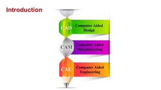
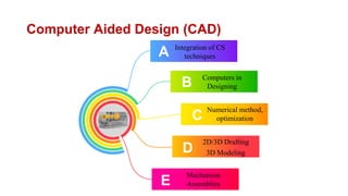
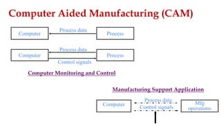
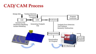
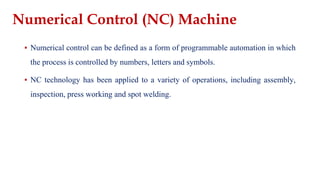
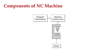
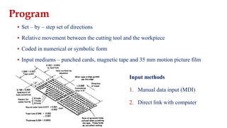
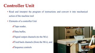
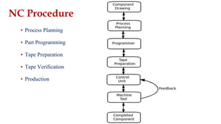
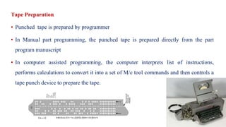
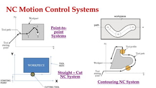
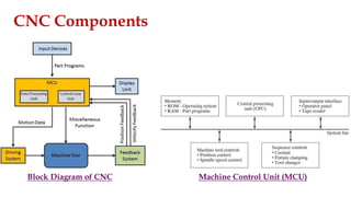
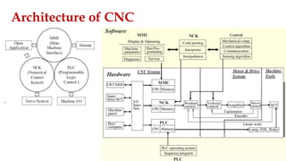
CNC Programming
▪ To increase the productivity
▪ To increase the quality
▪ To improve the communication
▪ To create a database
Implementation
Computer Aided
Design
CAD
CAM
CAE
Introduction
Computer Aided
Manufacturing
Computer Aided
Engineering
Computer Aided Design (CAD)
Integration of CS
techniques
A
B
C
D
E
Computers in
Designing
Numerical method,
optimization
2D/3D Drafting
3D Modeling
Mechanism
Assemblies
Computer Aided Manufacturing (CAM)
Computer Process
Process data
Control signals
Computer Process
Process data
Control signals
Computer Mfg
operations
Process data
Computer Monitoring and Control
Manufacturing Support Application
CAD/ CAM Process
NUMERICAL CONTROL
(NC)
MACHINE
▪ Numerical control can be defined as a form of programmable automation in which
the process is controlled by numbers, letters and symbols.
▪ NC technology has been applied to a variety of operations, including assembly,
inspection, press working and spot welding.
Numerical Control (NC) Machine
Machine
Control Unit
Power
Program
Instructions
Components of NC Machine
▪ Set – by – step set of directions
▪ Relative movement between the cutting tool and the workpiece
▪ Coded in numerical or symbolic form
▪ Input mediums – punched cards, magnetic tape and 35 mm motion picture film
Program
Input methods
1. Manual data input (MDI)
2. Direct link with computer
▪ Read and interpret the program of instructions and convert it into mechanical
action of the machine tool
▪ Elements of a controller Unit
✔Tape reader,
✔Data buffer,
✔Signal output channels (to the M/c)
✔Feed back channels (from the M/c), and
✔Sequence controls
Controller Unit
Tape Reader
▪ Electromechanical device for winding and reading the punched tape
▪ Data are read into the data buffer
Data Buffer
▪ To store the input instructions in logical blocks of information
▪ A block of information represents one complete step in the sequence of processing elements
Signal Output Channels
▪ Connected to the servomotors and other controls of the machine tool
▪ The instructions are sent through these channels to the M/c tool
Feedback Channels
▪ To make the certain instructions have been properly executed by the machine, feedback data
are sent back to the controller through the feedback channels
▪ The function of this closed loop is to assure that the table and work have been properly
located with respect to the tool
Sequence Controls
▪ It coordinates the activities of the other elements of the controller unit
▪ Reading
▪ Storing
▪ Signal output and so on.
▪ It is the part of NC system which performs useful work
▪ It consists of the worktable and spindle and controls to drive them
▪ It also includes cutting tools, work fixtures and other auxiliary equipment needed for
M/c’ing operations
Machine Tool
▪ Process Planning
▪ Part Programming
▪ Tape Preparation
▪ Tape Verification
▪ Production
NC Procedure
Process Planning
▪ Drawing interpretation
▪ Preparation of route sheet
▪ Sequence of operations to be performed
▪ Machines through which part must be routed
Part Programming
▪ Part programmers plans the process for the job and sequence of machining
▪ Manual Part Programming
- part program manuscript
▪ Computer Assisted Part Programming
- complex work geometries
Tape Preparation
▪ Punched tape is prepared by programmer
▪ In Manual part programming, the punched tape is prepared directly from the part
program manuscript
▪ In computer assisted programming, the computer interprets list of instructions,
performs calculations to convert it into a set of M/c tool commands and then controls a
tape punch device to prepare the tape.
Tape Verification
▪ The tape is given for checking the accuracy of the tape. (to discover the Error)
▪ Tape is checked by running it which plots the various tool movements on paper.
▪ Acid test – it involves trying to run it in the M/c tool to make a part
NC Motion Control Systems
Point-to-
point
Systems
Straight – Cut
NC System
Contouring NC System
▪ Linear Interpolation
▪ Circular Interpolation
▪ Helical Interpolation
▪ Parabolic Interpolation
▪ Cubic Interpolation
Interpolation
Absolute Versus Incremental Positioning
Architecture of NC machine tools
COMPUTER NUMERICAL
CONTROL (CNC)
Computer Numerical Control M/c
CNC Components
Block Diagram of CNC Machine Control Unit (MCU)
Drives
Electrical drives - Direct Current (DC) or Alternating Current (AC) servo motors
Hydraulic drives
▪ Large power to size ratio and provide stepless motion with great accuracy
▪ Hydraulic elements need special treatment to protect them against corrosion
Pneumatic drives
▪ Simple in construction and are cheaper
▪ Generate low power, have less positioning accuracy and are noisy
Feed Drive
Servo Driving Mechanism
▪ Operate with constant torque
▪ Maximum speed of around 2000 rpm and at a
minimum speed of 0.1 rpm
▪ Must run smoothly
▪ Extremely small positioning resolution
▪ High torque to weight ratio, low rotor inertia
▪ Quick response in case of contouring operation
Spindle Drive
Spindle Driving Mechanism ▪ Maintains the speed accurately
▪ Speed ranges can be from 10 to 20,000 rpm.
▪ High overload capacity is for unintended overloads
▪ Compact drive with highly smooth operation.
Electrical Drives
Electrical
motors
Servo Motor
DC Servo Motor Synchronous-type
AC Servo Motor
Induction-type
AC Servo Motor
Servo Motor
Recirculating Ball Screw
Encoder Resolver Encoder Vs
Resolver
CNC Control loop
▪ To minimize the velocity error or the position error
▪ Three independent control loops
▪ Position-control loop is located in a servo driving device
▪ Feedback control of velocity is applied to maintain a regular rotation speed in the spindle system
▪ Tacho-generator and optical encoder
CNC Control loop
CNC
Semi-
Closed
Closed Hybrid Open
Open Control loop
▪ No feedback
▪ Accuracy of control is not high and a stepping motor is used
▪ Does not need a detector and a feedback circuit
▪ The structure is very simple
▪ Accuracy of the driving system is directly influenced by the
accuracy of the stepping motor, ball screw, and transmission.
Semi-Closed loop
▪ Position detector is attached to the shaft of a servo motor
▪ The position accuracy of the axis has a great influence on the accuracy of the ball screw
▪ Precision ball screw, the problem with accuracy has practically been overcome
▪ To increase the positional accuracy pitch-error compensation and backlash compensation
▪ The pitch-error compensation method is that, the specific pitch, the instructions to the servo
driver system are modified to remove the accumulation of positional error.
▪ The backlash compensation method is that, whenever the moving direction is changed, additional
pulses corresponding to the amount of backlash are sent to the servo driver system.
▪ Usage of the hi-lead-type ball screw with large pitch for high-speed machining has increased.
Closed loop
▪ The amount of backlash can be varied according to the weight of the workpiece and location
▪ Accumulation pitch error of the ball screw is varied according to the temperature.
▪ The length of the ball screw is limited
▪ Rack and pinion driving system is used in large-scale machine tools, the accuracy is limited
▪ The location of the position detector
Closed loop
▪ The position detector is attached to the machine table and the actual position error is fed back to
the control system.
▪ The position accuracy of closed loop is very high.
▪ The resonance frequency of the machine body, stick slip, and lost motion have an influence on
the servo characteristics because the machine body is included in the position control loop.
▪ Following error, the difference between the command position and the detected position,
occurs and the servo is rotated at a speed proportional to this following error in order to
decrease it.
▪ The decreasing speed of the following error is related to the gain of the position control loop.
Closed loop
▪ Gain is an factor defines the property of the servo system
▪ The gain increases, the response speed and dynamic accuracy increase
▪ High gain makes the servo system unstable. Unstable means hunting, which is impossible to stop
at the command position due to repetitive overshooting and returning.
▪ In the closed loop, if the resonance frequency of the machine driving system is not sufficiently
higher than the gain, the control loop system becomes unstable.
▪ Stick slip and lost motion are the factors that give rise to hunting. So, It is necessary to increase
the resonance frequency and, for this, it is necessary to increase the rigidity of the machine,
decrease the friction coefficient of the perturbation surface, and remove the cause of lost motion.
Hybrid loop
▪ In closed loop, it is necessary to lower the gain in the case when it is difficult to increase the
rigidity in proportion to the weight of the moving element or decrease lost motion as in a
heavy machine.
▪ If the gain is very low, the performance becomes poor with respect to positioning time and
accuracy.
Hybrid loop
▪ In the hybrid loop; semi-closed loop, where the position is detected from the shaft of a
motor, and closed loop, which is based on a linear scale.
▪ In the semi-closed loop, it is possible to control with high gain because the machine is not
included in the control system.
▪ The closed loop increases accuracy by compensating the error that the semi-closed loop
cannot control. Because the closed loop is used for compensating only positional error, it is
well behaved in spite of low gain.
▪ By combining the closed loop and the semi-closed loop, it is possible to obtain high accuracy
with high gain in an ill-conditioned machine.
Architecture of CNC
▪ CNC machine tools consist of CNC, motor drive system, and machine tools.
▪ The output of the position control, is sent to the motor drive system, the motor drive system
operates a servo motor by velocity control and torque control
▪ In the CNC system, the processor modules that process the functions of the MMI unit, NCK
unit, and the PLC unit consist of a main processor, a system ROM and a RAM
▪ The process module is connected with an interface that is equipped with key input, display
control, external input and system bus.
▪ An Analog/Digital input/output device for direct communication with external machines and
a interface for linking an external motor driving device with an input/output module.
Architecture of CNC
Architecture of CNC
▪ Velocity commands in analog format were used for transmitting signals to the motor driving
system.
▪ Because noise occurs while transmitting analog signals, not only are digital signals used for
velocity command but also digital communication is used for communication between the
CNC system and the motor driving system.
▪ In digital communication there is a possibility to exchange a variety of data and remove
noise by using optical cables, increases accuracy by removing noise.
▪ The connection between a CNC system and a variety of sensor and mechanical devices is
done via only one communication line
Architecture of CNC
▪ The CNC system consists of MMI functions that support user operation and program editing
and display machine status
▪ NCK functions that execute interpretation, interpolation and control
▪ PLC functions that carry out sequential logic programs.
MMI Function
▪ Operation functions
▪ Parameter-setting functions
▪ Program-editing functions
▪ Monitoring and alarm functions
▪ Service/utility functions
Operation functions
▪ Support operation of the machine and the display that
shows the machine status
▪ The position, distance-to-go, and feed of each axis,
spindle speed, the block that is being executed, and
override status
▪ To help machine operation such as jog, MDI,
program search, program editor, and tool
management
Parameter-setting functions
▪ Machine parameters that are used for setting machine
regulation, servo/spindle driving system, tool offset,
work coordinate, and safety boundary
▪ Program parameters that should be set during editing
of the part program
▪ Customization parameters that are used to adapt the
machine to user requirements.
▪ To provide the interface for setting, storing, and
searching parameters.
Program-editing functions
▪ To edit and modify the part program
▪ To know G/M-codes and carry out mathematical
calculations in order to generate the G-code part
program.
▪ Because mathematical calculation makes it difficult
to edit part programs, CNC has recently begun to
employ conversational programming systems.
▪ By interaction with the GUI a user can quickly
generate a part program for drilling without
memorizing the input attributes for G-code cycles.
Monitoring and Alarm functions
▪ The CNC system always informs a user of the
machine status by monitoring and, execute the
necessary tasks and inform the user of the result.
▪ Essential when machine tools are executing at
high speed.
▪ Provides monitoring information such as the
alarm status, emergency recovery method, PLC
status, and ladder diagram under execution.
NCK Functions
NCK Functions
▪ Interpreter
▪ Interpolator
▪ Acceleration/ Deceleration control
▪ Position Control
Interpreter
▪ Interpreting the ASCII blocks in the part program
▪ Storing interpreted data in internal memory for the interpolator.
▪ Reads and interprets the next block while the command is being performed.
▪ If the time to interpret the block is longer than the time to finish the command, the machine
should wait for the completion of interpretation of the next block so that a machine stop
cannot be avoided.
▪ Buffer that temporarily stores the interpreted data is used, always keeps a sufficient number
of interpreted data and all interpreted data are stored in the buffer.
Coordinate System
Interpolator
▪ Reading the data from the internal data buffer, calculating the position and velocity per unit
time of each axis, and storing the result for the acceleration/deceleration controller.
▪ A linear interpolator and a circular interpolator are typically used in an NC system and a
parabola interpolator and a spline interpolator are used for part of an NC system.
▪ The interpolator generates a pulse corresponding to the path data according to the type of
path (e.g. line, circle, parabola, and spline) and sends the pulse to the FIFO buffer.
▪ The number of pulses is decided based on the length of path and the frequency of the pulses
is based on the velocity.
Interpolator
▪ The displacement per pulse determines the accuracy
▪ Axis moves 0.002 mm per pulse, the accuracy of the NC system is 0.002 mm.
▪ The NC system should generate 25000 pulses for the moving part to move as much as 50
mm and 8333 pulses per second to move at a speed of 1m per minute.
▪ The data in the FIFO buffer is transmitted to the next function via a fine interpolator, which
interpolates precisely the interpolated data and, if not necessary, does not have to be
implemented.
Acceleration/ Deceleration Control
▪ Large mechanical vibration and shock occur whenever part movement starts and stops.
▪ To prevent mechanical vibration and shock, the filtering for Acceleration/ Deceleration
Control is executed
▪ Acceleration/ Deceleration After Interpolation (ADAI)
▪ Acceleration/ Deceleration Before Interpolation (ADBI)
Position Control
▪ The data from an acceleration/deceleration controller is sent to a position controller
▪ Position control is carried out based on the transmitted data in a constant time interval.
▪ A position control typically means a PID controller and issues velocity commands to the
motor driving system
▪ In order to minimize the position difference between the commanded position and the
actual position found from the encoder.
Programmable Logic Controller (PLC)
▪ The logic controller is used to execute sequential control in a machine and an industry.
▪ Earlier, logic control was executed by using hardware that consisted of relays, counters,
timers, and circuits. (hardware-based logic controller)
▪ Recent PLC systems consist of a few electrical devices including microprocessors and
memory, able to carry out logical operations, a counter function, a timer function and
arithmetic operations. (software-based logic controller)
PLC advantages
▪ Flexibility
▪ Scalability
▪ Economic efficiency
▪ Miniaturization
▪ Reliability
▪ Performance
PLC Architecture
PLC Function
▪ User creates the application program used in the PLC unit by using an external PLC program editor and inputs the
application program to the PLC unit.
▪ At this stage, a specific device is used for helping the user to edit the program and is called a programmer or loader.
▪ The programmer consists of the editor that creates a program and the compiler that converts the program into the PLC-
interpretable language.
▪ The reason why a compiler is used is that a compiled program is more efficient and hence the PLC can run the
program quickly. The compiled PLC program is transmitted to the CPU module.
▪ The status of the PLC that is being executed in the CPU module is sent to the PLC program for a user to monitor the
activity status.
▪ The module that reads the program edited by the Loader and executes sequential logic operations is the Executer,
which is the core of a PLC kernel. The Executer is repeated successively, reading the input points, doing logic
operations of the program, and sending the results to the output points via the output module.
PLC Function
▪ Auxiliary controller that assists with part of the functions of the NCK unit.
▪ Circuit dedicated to communicating with NCK.
▪ Dual-port RAM for supporting high-speed communication.
▪ Memory for the exchanged data during high-speed communication with NCK.
▪ High-speed input module for high-speed control such as turret control.

Introduction.pptx

  • 1.
  • 2.
    ▪ To increasethe productivity ▪ To increase the quality ▪ To improve the communication ▪ To create a database Implementation
  • 3.
  • 4.
    Computer Aided Design(CAD) Integration of CS techniques A B C D E Computers in Designing Numerical method, optimization 2D/3D Drafting 3D Modeling Mechanism Assemblies
  • 5.
    Computer Aided Manufacturing(CAM) Computer Process Process data Control signals Computer Process Process data Control signals Computer Mfg operations Process data Computer Monitoring and Control Manufacturing Support Application
  • 6.
  • 7.
  • 8.
    ▪ Numerical controlcan be defined as a form of programmable automation in which the process is controlled by numbers, letters and symbols. ▪ NC technology has been applied to a variety of operations, including assembly, inspection, press working and spot welding. Numerical Control (NC) Machine
  • 9.
  • 10.
    ▪ Set –by – step set of directions ▪ Relative movement between the cutting tool and the workpiece ▪ Coded in numerical or symbolic form ▪ Input mediums – punched cards, magnetic tape and 35 mm motion picture film Program Input methods 1. Manual data input (MDI) 2. Direct link with computer
  • 11.
    ▪ Read andinterpret the program of instructions and convert it into mechanical action of the machine tool ▪ Elements of a controller Unit ✔Tape reader, ✔Data buffer, ✔Signal output channels (to the M/c) ✔Feed back channels (from the M/c), and ✔Sequence controls Controller Unit
  • 12.
    Tape Reader ▪ Electromechanicaldevice for winding and reading the punched tape ▪ Data are read into the data buffer Data Buffer ▪ To store the input instructions in logical blocks of information ▪ A block of information represents one complete step in the sequence of processing elements Signal Output Channels ▪ Connected to the servomotors and other controls of the machine tool ▪ The instructions are sent through these channels to the M/c tool
  • 13.
    Feedback Channels ▪ Tomake the certain instructions have been properly executed by the machine, feedback data are sent back to the controller through the feedback channels ▪ The function of this closed loop is to assure that the table and work have been properly located with respect to the tool Sequence Controls ▪ It coordinates the activities of the other elements of the controller unit ▪ Reading ▪ Storing ▪ Signal output and so on.
  • 14.
    ▪ It isthe part of NC system which performs useful work ▪ It consists of the worktable and spindle and controls to drive them ▪ It also includes cutting tools, work fixtures and other auxiliary equipment needed for M/c’ing operations Machine Tool
  • 15.
    ▪ Process Planning ▪Part Programming ▪ Tape Preparation ▪ Tape Verification ▪ Production NC Procedure
  • 16.
    Process Planning ▪ Drawinginterpretation ▪ Preparation of route sheet ▪ Sequence of operations to be performed ▪ Machines through which part must be routed Part Programming ▪ Part programmers plans the process for the job and sequence of machining ▪ Manual Part Programming - part program manuscript ▪ Computer Assisted Part Programming - complex work geometries
  • 17.
    Tape Preparation ▪ Punchedtape is prepared by programmer ▪ In Manual part programming, the punched tape is prepared directly from the part program manuscript ▪ In computer assisted programming, the computer interprets list of instructions, performs calculations to convert it into a set of M/c tool commands and then controls a tape punch device to prepare the tape.
  • 18.
    Tape Verification ▪ Thetape is given for checking the accuracy of the tape. (to discover the Error) ▪ Tape is checked by running it which plots the various tool movements on paper. ▪ Acid test – it involves trying to run it in the M/c tool to make a part
  • 19.
    NC Motion ControlSystems Point-to- point Systems Straight – Cut NC System Contouring NC System
  • 20.
    ▪ Linear Interpolation ▪Circular Interpolation ▪ Helical Interpolation ▪ Parabolic Interpolation ▪ Cubic Interpolation Interpolation
  • 21.
  • 22.
    Architecture of NCmachine tools
  • 23.
  • 24.
  • 25.
    CNC Components Block Diagramof CNC Machine Control Unit (MCU)
  • 26.
    Drives Electrical drives -Direct Current (DC) or Alternating Current (AC) servo motors Hydraulic drives ▪ Large power to size ratio and provide stepless motion with great accuracy ▪ Hydraulic elements need special treatment to protect them against corrosion Pneumatic drives ▪ Simple in construction and are cheaper ▪ Generate low power, have less positioning accuracy and are noisy
  • 27.
    Feed Drive Servo DrivingMechanism ▪ Operate with constant torque ▪ Maximum speed of around 2000 rpm and at a minimum speed of 0.1 rpm ▪ Must run smoothly ▪ Extremely small positioning resolution ▪ High torque to weight ratio, low rotor inertia ▪ Quick response in case of contouring operation
  • 28.
    Spindle Drive Spindle DrivingMechanism ▪ Maintains the speed accurately ▪ Speed ranges can be from 10 to 20,000 rpm. ▪ High overload capacity is for unintended overloads ▪ Compact drive with highly smooth operation.
  • 29.
  • 30.
    Servo Motor DC ServoMotor Synchronous-type AC Servo Motor Induction-type AC Servo Motor
  • 31.
  • 32.
  • 33.
  • 34.
    CNC Control loop ▪To minimize the velocity error or the position error ▪ Three independent control loops ▪ Position-control loop is located in a servo driving device ▪ Feedback control of velocity is applied to maintain a regular rotation speed in the spindle system ▪ Tacho-generator and optical encoder
  • 35.
  • 36.
    Open Control loop ▪No feedback ▪ Accuracy of control is not high and a stepping motor is used ▪ Does not need a detector and a feedback circuit ▪ The structure is very simple ▪ Accuracy of the driving system is directly influenced by the accuracy of the stepping motor, ball screw, and transmission.
  • 37.
    Semi-Closed loop ▪ Positiondetector is attached to the shaft of a servo motor ▪ The position accuracy of the axis has a great influence on the accuracy of the ball screw ▪ Precision ball screw, the problem with accuracy has practically been overcome ▪ To increase the positional accuracy pitch-error compensation and backlash compensation ▪ The pitch-error compensation method is that, the specific pitch, the instructions to the servo driver system are modified to remove the accumulation of positional error. ▪ The backlash compensation method is that, whenever the moving direction is changed, additional pulses corresponding to the amount of backlash are sent to the servo driver system. ▪ Usage of the hi-lead-type ball screw with large pitch for high-speed machining has increased.
  • 38.
    Closed loop ▪ Theamount of backlash can be varied according to the weight of the workpiece and location ▪ Accumulation pitch error of the ball screw is varied according to the temperature. ▪ The length of the ball screw is limited ▪ Rack and pinion driving system is used in large-scale machine tools, the accuracy is limited ▪ The location of the position detector
  • 39.
    Closed loop ▪ Theposition detector is attached to the machine table and the actual position error is fed back to the control system. ▪ The position accuracy of closed loop is very high. ▪ The resonance frequency of the machine body, stick slip, and lost motion have an influence on the servo characteristics because the machine body is included in the position control loop. ▪ Following error, the difference between the command position and the detected position, occurs and the servo is rotated at a speed proportional to this following error in order to decrease it. ▪ The decreasing speed of the following error is related to the gain of the position control loop.
  • 40.
    Closed loop ▪ Gainis an factor defines the property of the servo system ▪ The gain increases, the response speed and dynamic accuracy increase ▪ High gain makes the servo system unstable. Unstable means hunting, which is impossible to stop at the command position due to repetitive overshooting and returning. ▪ In the closed loop, if the resonance frequency of the machine driving system is not sufficiently higher than the gain, the control loop system becomes unstable. ▪ Stick slip and lost motion are the factors that give rise to hunting. So, It is necessary to increase the resonance frequency and, for this, it is necessary to increase the rigidity of the machine, decrease the friction coefficient of the perturbation surface, and remove the cause of lost motion.
  • 41.
    Hybrid loop ▪ Inclosed loop, it is necessary to lower the gain in the case when it is difficult to increase the rigidity in proportion to the weight of the moving element or decrease lost motion as in a heavy machine. ▪ If the gain is very low, the performance becomes poor with respect to positioning time and accuracy.
  • 42.
    Hybrid loop ▪ Inthe hybrid loop; semi-closed loop, where the position is detected from the shaft of a motor, and closed loop, which is based on a linear scale. ▪ In the semi-closed loop, it is possible to control with high gain because the machine is not included in the control system. ▪ The closed loop increases accuracy by compensating the error that the semi-closed loop cannot control. Because the closed loop is used for compensating only positional error, it is well behaved in spite of low gain. ▪ By combining the closed loop and the semi-closed loop, it is possible to obtain high accuracy with high gain in an ill-conditioned machine.
  • 43.
  • 44.
    ▪ CNC machinetools consist of CNC, motor drive system, and machine tools. ▪ The output of the position control, is sent to the motor drive system, the motor drive system operates a servo motor by velocity control and torque control ▪ In the CNC system, the processor modules that process the functions of the MMI unit, NCK unit, and the PLC unit consist of a main processor, a system ROM and a RAM ▪ The process module is connected with an interface that is equipped with key input, display control, external input and system bus. ▪ An Analog/Digital input/output device for direct communication with external machines and a interface for linking an external motor driving device with an input/output module. Architecture of CNC
  • 45.
    Architecture of CNC ▪Velocity commands in analog format were used for transmitting signals to the motor driving system. ▪ Because noise occurs while transmitting analog signals, not only are digital signals used for velocity command but also digital communication is used for communication between the CNC system and the motor driving system. ▪ In digital communication there is a possibility to exchange a variety of data and remove noise by using optical cables, increases accuracy by removing noise. ▪ The connection between a CNC system and a variety of sensor and mechanical devices is done via only one communication line
  • 46.
    Architecture of CNC ▪The CNC system consists of MMI functions that support user operation and program editing and display machine status ▪ NCK functions that execute interpretation, interpolation and control ▪ PLC functions that carry out sequential logic programs.
  • 47.
    MMI Function ▪ Operationfunctions ▪ Parameter-setting functions ▪ Program-editing functions ▪ Monitoring and alarm functions ▪ Service/utility functions
  • 48.
    Operation functions ▪ Supportoperation of the machine and the display that shows the machine status ▪ The position, distance-to-go, and feed of each axis, spindle speed, the block that is being executed, and override status ▪ To help machine operation such as jog, MDI, program search, program editor, and tool management
  • 49.
    Parameter-setting functions ▪ Machineparameters that are used for setting machine regulation, servo/spindle driving system, tool offset, work coordinate, and safety boundary ▪ Program parameters that should be set during editing of the part program ▪ Customization parameters that are used to adapt the machine to user requirements. ▪ To provide the interface for setting, storing, and searching parameters.
  • 50.
    Program-editing functions ▪ Toedit and modify the part program ▪ To know G/M-codes and carry out mathematical calculations in order to generate the G-code part program. ▪ Because mathematical calculation makes it difficult to edit part programs, CNC has recently begun to employ conversational programming systems. ▪ By interaction with the GUI a user can quickly generate a part program for drilling without memorizing the input attributes for G-code cycles.
  • 51.
    Monitoring and Alarmfunctions ▪ The CNC system always informs a user of the machine status by monitoring and, execute the necessary tasks and inform the user of the result. ▪ Essential when machine tools are executing at high speed. ▪ Provides monitoring information such as the alarm status, emergency recovery method, PLC status, and ladder diagram under execution.
  • 52.
  • 53.
    NCK Functions ▪ Interpreter ▪Interpolator ▪ Acceleration/ Deceleration control ▪ Position Control
  • 54.
    Interpreter ▪ Interpreting theASCII blocks in the part program ▪ Storing interpreted data in internal memory for the interpolator. ▪ Reads and interprets the next block while the command is being performed. ▪ If the time to interpret the block is longer than the time to finish the command, the machine should wait for the completion of interpretation of the next block so that a machine stop cannot be avoided. ▪ Buffer that temporarily stores the interpreted data is used, always keeps a sufficient number of interpreted data and all interpreted data are stored in the buffer.
  • 55.
  • 56.
    Interpolator ▪ Reading thedata from the internal data buffer, calculating the position and velocity per unit time of each axis, and storing the result for the acceleration/deceleration controller. ▪ A linear interpolator and a circular interpolator are typically used in an NC system and a parabola interpolator and a spline interpolator are used for part of an NC system. ▪ The interpolator generates a pulse corresponding to the path data according to the type of path (e.g. line, circle, parabola, and spline) and sends the pulse to the FIFO buffer. ▪ The number of pulses is decided based on the length of path and the frequency of the pulses is based on the velocity.
  • 57.
    Interpolator ▪ The displacementper pulse determines the accuracy ▪ Axis moves 0.002 mm per pulse, the accuracy of the NC system is 0.002 mm. ▪ The NC system should generate 25000 pulses for the moving part to move as much as 50 mm and 8333 pulses per second to move at a speed of 1m per minute. ▪ The data in the FIFO buffer is transmitted to the next function via a fine interpolator, which interpolates precisely the interpolated data and, if not necessary, does not have to be implemented.
  • 58.
    Acceleration/ Deceleration Control ▪Large mechanical vibration and shock occur whenever part movement starts and stops. ▪ To prevent mechanical vibration and shock, the filtering for Acceleration/ Deceleration Control is executed ▪ Acceleration/ Deceleration After Interpolation (ADAI) ▪ Acceleration/ Deceleration Before Interpolation (ADBI)
  • 59.
    Position Control ▪ Thedata from an acceleration/deceleration controller is sent to a position controller ▪ Position control is carried out based on the transmitted data in a constant time interval. ▪ A position control typically means a PID controller and issues velocity commands to the motor driving system ▪ In order to minimize the position difference between the commanded position and the actual position found from the encoder.
  • 60.
    Programmable Logic Controller(PLC) ▪ The logic controller is used to execute sequential control in a machine and an industry. ▪ Earlier, logic control was executed by using hardware that consisted of relays, counters, timers, and circuits. (hardware-based logic controller) ▪ Recent PLC systems consist of a few electrical devices including microprocessors and memory, able to carry out logical operations, a counter function, a timer function and arithmetic operations. (software-based logic controller)
  • 61.
    PLC advantages ▪ Flexibility ▪Scalability ▪ Economic efficiency ▪ Miniaturization ▪ Reliability ▪ Performance
  • 62.
  • 63.
    PLC Function ▪ Usercreates the application program used in the PLC unit by using an external PLC program editor and inputs the application program to the PLC unit. ▪ At this stage, a specific device is used for helping the user to edit the program and is called a programmer or loader. ▪ The programmer consists of the editor that creates a program and the compiler that converts the program into the PLC- interpretable language. ▪ The reason why a compiler is used is that a compiled program is more efficient and hence the PLC can run the program quickly. The compiled PLC program is transmitted to the CPU module. ▪ The status of the PLC that is being executed in the CPU module is sent to the PLC program for a user to monitor the activity status. ▪ The module that reads the program edited by the Loader and executes sequential logic operations is the Executer, which is the core of a PLC kernel. The Executer is repeated successively, reading the input points, doing logic operations of the program, and sending the results to the output points via the output module.
  • 64.
    PLC Function ▪ Auxiliarycontroller that assists with part of the functions of the NCK unit. ▪ Circuit dedicated to communicating with NCK. ▪ Dual-port RAM for supporting high-speed communication. ▪ Memory for the exchanged data during high-speed communication with NCK. ▪ High-speed input module for high-speed control such as turret control.
  • 65.
    PLC Function ▪ Auxiliarycontroller that assists with part of the functions of the NCK unit. ▪ Circuit dedicated to communicating with NCK. ▪ Dual-port RAM for supporting high-speed communication. ▪ Memory for the exchanged data during high-speed communication with NCK. ▪ High-speed input module for high-speed control such as turret control.