introduction to computer architecture Chapter_03.pptx
1.
Department of ComputerEngineering
Chapter 3: Top Level View of Computer
Function and Interconnection
Computer Architecture
and Organization
2.
2
Top Level Viewof Computer System
Computer Architecture and Organization
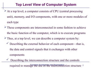
At a top level, a computer consists of CPU (central processing
unit), memory, and I/O components, with one or more modules of
each type
These components are interconnected in some fashion to achieve
the basic function of the computer, which is to execute programs
Thus, at a top level, we can describe a computer system by:
Describing the external behavior of each component—that is,
the data and control signals that it exchanges with other
components
Describing the interconnection structure and the controls
required to manage the use of the interconnection structure
3.
3
Hardwired Program Concept
ComputerArchitecture and Organization
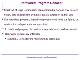
Small set of logic Components can combined in various way to store
binary data and perform arithmetic logical operation on that data
For hardwired program, logical components need to be configured or
rewired for each particular computation
In hardwired program, the system accepts data and produces results
Hardwired systems are inflexible
· Solution , Use Software Programming techniques
4.
4
Software Program Concept
ComputerArchitecture and Organization
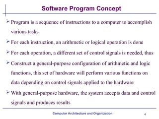
Program is a sequence of instructions to a computer to accomplish
various tasks
For each instruction, an arithmetic or logical operation is done
For each operation, a different set of control signals is needed, thus
Construct a general-purpose configuration of arithmetic and logic
functions, this set of hardware will perform various functions on
data depending on control signals applied to the hardware
With general-purpose hardware, the system accepts data and control
signals and produces results
5.
5
Software Program Concept
ComputerArchitecture and Organization
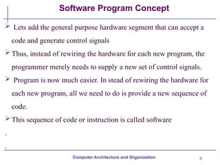
Lets add the general purpose hardware segment that can accept a
code and generate control signals
Thus, instead of rewiring the hardware for each new program, the
programmer merely needs to supply a new set of control signals.
Program is now much easier. In stead of rewiring the hardware for
each new program, all we need to do is provide a new sequence of
code.
This sequence of code or instruction is called software
.
.
6.
6
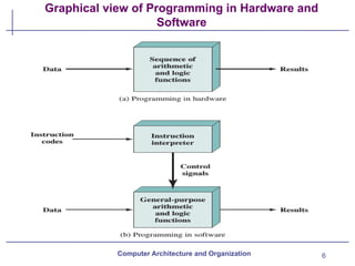
Graphical view ofProgramming in Hardware and
Software
Computer Architecture and Organization
7.
7
Function of ControlUnit
For each operation a unique code is provided to control unit of the
processor
E.g. ADD, MOVE
A hardware segment accepts the code and issues the control signals
for various modules in the computer
Computer Architecture and Organization
8.
8
Computer components
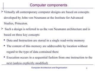
Virtually allcontemporary computer designs are based on concepts
developed by John von Neumann at the Institute for Advanced
Studies, Princeton.
Such a design is referred to as the von Neumann architecture and is
based on three key concepts
· Data and Instruction are stored in a single read-write memory
· The content of this memory are addressable by location without
regard to the type of data contained there
· Execution occurs in a sequential fashion from one instruction to the
next (unless explicitly modified)
Computer Architecture and Organization
9.
9
Computer Components
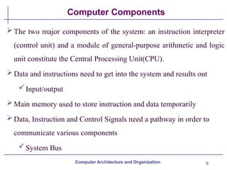
The twomajor components of the system: an instruction interpreter
(control unit) and a module of general-purpose arithmetic and logic
unit constitute the Central Processing Unit(CPU).
Data and instructions need to get into the system and results out
Input/output
Main memory used to store instruction and data temporarily
Data, Instruction and Control Signals need a pathway in order to
communicate various components
System Bus
Computer Architecture and Organization
11
Computer Components
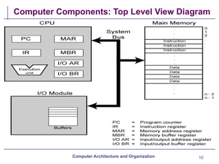
The CPUexchanges data with memory, for this purpose, it
typically makes use of two internal (to the CPU) registers
A memory address register (MAR), which specifies the
address in memory for the next read or write, and a
memory buffer register (MBR), which contains the data to be
written into memory or receives the data read from memory
The CPU exchanges data with I/O, for this purpose there is two
registers
I/O address register (I/OAR), specifies a particular I/O device.
Computer Architecture and Organization
12.
12
Computer Components
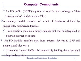
An I/Obuffer (I/OBR) register is used for the exchange of data
between an I/O module and the CPU
A memory module consists of a set of locations, defined by
sequentially numbered addresses.
Each location contains a binary number that can be interpreted as
either an instruction or data
An I/O module transfers data from external devices to CPU and
memory, and vice versa
It contains internal buffers for temporarily holding these data until
they can be sent on.
Computer Architecture and Organization
13.
13
Computer Functions
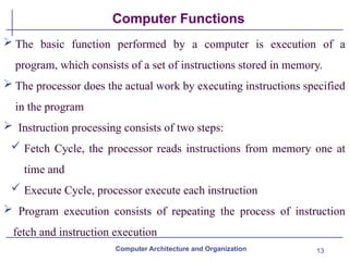
Thebasic function performed by a computer is execution of a
program, which consists of a set of instructions stored in memory.
The processor does the actual work by executing instructions specified
in the program
Instruction processing consists of two steps:
Fetch Cycle, the processor reads instructions from memory one at
time and
Execute Cycle, processor execute each instruction
Program execution consists of repeating the process of instruction
fetch and instruction execution
Computer Architecture and Organization
14.
14
Instruction cycle
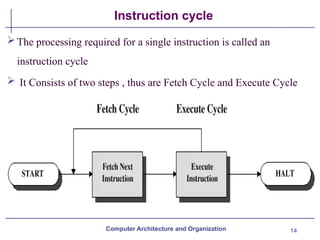
The processingrequired for a single instruction is called an
instruction cycle
It Consists of two steps , thus are Fetch Cycle and Execute Cycle
Computer Architecture and Organization
15.
15
Fetch cycle
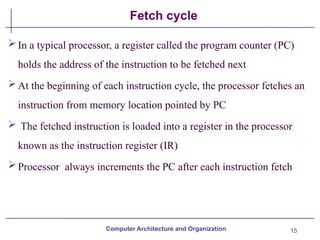
In atypical processor, a register called the program counter (PC)
holds the address of the instruction to be fetched next
At the beginning of each instruction cycle, the processor fetches an
instruction from memory location pointed by PC
The fetched instruction is loaded into a register in the processor
known as the instruction register (IR)
Processor always increments the PC after each instruction fetch
Computer Architecture and Organization
16.
16
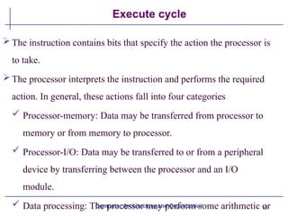
Execute cycle
The instructioncontains bits that specify the action the processor is
to take.
The processor interprets the instruction and performs the required
action. In general, these actions fall into four categories
Processor-memory: Data may be transferred from processor to
memory or from memory to processor.
Processor-I/O: Data may be transferred to or from a peripheral
device by transferring between the processor and an I/O
module.
Data processing: The processor may perform some arithmetic or
Computer Architecture and Organization
17.
17
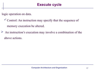
Execute cycle
logic operationon data.
Control: An instruction may specify that the sequence of
memory execution be altered.
An instruction’s execution may involve a combination of the
above actions.
Computer Architecture and Organization
18.
18
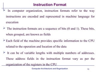
Instruction Format
Incomputer organization, instruction formats refer to the way
instructions are encoded and represented in machine language for
execution
The instruction formats are a sequence of bits (0 and 1). These bits,
when grouped, are known as fields
Each field of the machine provides specific information to the CPU
related to the operation and location of the data
It can be of variable lengths with multiple numbers of addresses.
These address fields in the instruction format vary as per the
organization of the registers in the CPU
Computer Architecture and Organization
19.
19
Instruction Format
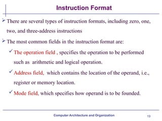
There areseveral types of instruction formats, including zero, one,
two, and three-address instructions
The most common fields in the instruction format are:
The operation field , specifies the operation to be performed
such as arithmetic and logical operation.
Address field, which contains the location of the operand, i.e.,
register or memory location.
Mode field, which specifies how operand is to be founded.
Computer Architecture and Organization
20.
20
Instruction Format
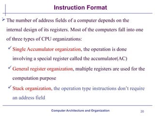
The numberof address fields of a computer depends on the
internal design of its registers. Most of the computers fall into one
of three types of CPU organizations:
Single Accumulator organization, the operation is done
involving a special register called the accumulator(AC)
General register organization, multiple registers are used for the
computation purpose
Stack organization, the operation type instructions don’t require
an address field
Computer Architecture and Organization
21.
21
Instruction Format Example
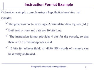
Considera simple example using a hypothetical machine that
includes
The processor contains a single Accumulator data register (AC)
Both instructions and data are 16 bits long
The instruction format provides 4 bits for the opcode, so that
there are 16 different opcodes, and
12 bits for address field, so 4096 (4K) words of memory can
be directly addressed.
Computer Architecture and Organization
22.
22
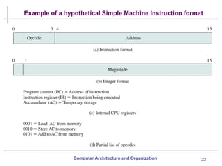
Example of ahypothetical Simple Machine Instruction format
Computer Architecture and Organization
25
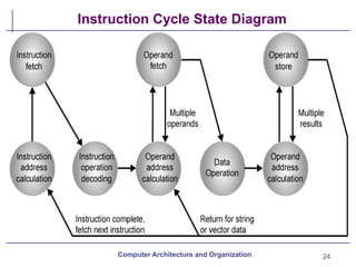
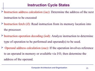
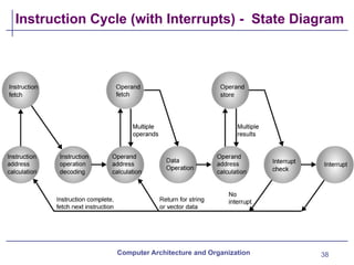
Instruction Cycle States
ComputerArchitecture and Organization
Instruction address calculation (iac): Determine the address of the next
instruction to be executed
Instruction fetch (if): Read instruction from its memory location into
the processor.
Instruction operation decoding (iod): Analyze instruction to determine
type of operation to be performed and operand(s) to be used.
Operand address calculation (oac): If the operation involves reference
to an operand in memory or available via I/O, then determine the
address of the operand.
26.
26
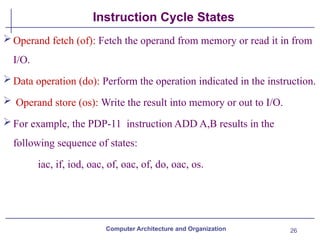
Instruction Cycle States
ComputerArchitecture and Organization
Operand fetch (of): Fetch the operand from memory or read it in from
I/O.
Data operation (do): Perform the operation indicated in the instruction.
Operand store (os): Write the result into memory or out to I/O.
For example, the PDP-11 instruction ADD A,B results in the
following sequence of states:
iac, if, iod, oac, of, oac, of, do, oac, os.
27.
27
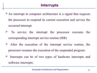
Interrupts
Computer Architecture andOrganization
An interrupt in computer architecture is a signal that requests
the processor to suspend its current execution and service the
occurred interrupt
To service the interrupt the processor executes the
corresponding interrupt service routine (ISR)
After the execution of the interrupt service routine, the
processor resumes the execution of the suspended program.
Interrupts can be of two types of hardware interrupts and
software interrupts.
29
Interrupts
Computer Architecture andOrganization
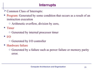
Common Class of Interrupts:
· Program: Generated by some condition that occurs as a result of an
instruction execution
o Arithmetic overflow, division by zero,
· Timer
o Generated by internal processor timer
· I/O
o Generated by I/O controller
· Hardware failure
o Generated by a failure such as power failure or memory parity
error.
30.
30
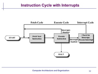
Interrupt Cycle
Computer Architectureand Organization
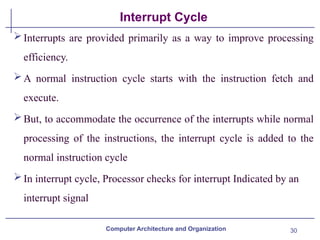
Interrupts are provided primarily as a way to improve processing
efficiency.
A normal instruction cycle starts with the instruction fetch and
execute.
But, to accommodate the occurrence of the interrupts while normal
processing of the instructions, the interrupt cycle is added to the
normal instruction cycle
In interrupt cycle, Processor checks for interrupt Indicated by an
interrupt signal
31.
31
Interrupt Cycle
Computer Architectureand Organization
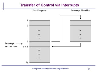
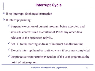
If no interrupt, fetch next instruction
If interrupt pending:
Suspend execution of current program being executed and
saves its context such as content of PC & any other data
relevant to the processor activity.
Set PC to the starting address of interrupt handler routine
Execute interrupt handler routine, when it becomes completed
the processor can resume execution of the user program at the
point of interruption
33
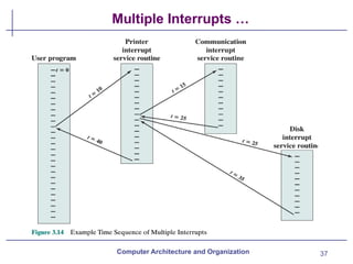
Multiple Interrupts
Computer Architectureand Organization
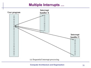
Two approaches can be taken to dealing with multiple interrupts.
The first is to disable interrupts while an interrupt is being
processed.
A disabled interrupt simply means that the processor can and will
ignore that interrupt request signal. If an interrupt occurs during this
time, it generally remains pending and will be checked by the
processor after the processor has enabled interrupts.
After the interrupt handler routine completes, interrupts are enabled
before resuming the user program
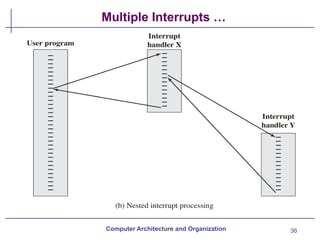
34.
34
Multiple Interrupts
Computer Architectureand Organization
The drawback to the preceding approach is that it does not take
into account relative priority or time-critical needs
A second approach is to define priorities for interrupts and to
allow an interrupt of higher priority to cause a lower-priority
interrupt handler to be itself interrupted
39
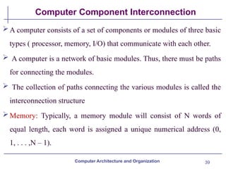
Computer Component Interconnection
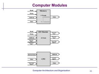
Acomputer consists of a set of components or modules of three basic
types ( processor, memory, I/O) that communicate with each other.
A computer is a network of basic modules. Thus, there must be paths
for connecting the modules.
The collection of paths connecting the various modules is called the
interconnection structure
Memory: Typically, a memory module will consist of N words of
equal length, each word is assigned a unique numerical address (0,
1, . . . ,N – 1).
Computer Architecture and Organization
40.
40
Computer Component Interconnection
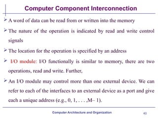
Aword of data can be read from or written into the memory
The nature of the operation is indicated by read and write control
signals
The location for the operation is specified by an address
I/O module: I/O functionally is similar to memory, there are two
operations, read and write. Further,
An I/O module may control more than one external device. We can
refer to each of the interfaces to an external device as a port and give
each a unique address (e.g., 0, 1, . . . ,M– 1).
Computer Architecture and Organization
41.
41
Computer Component Interconnection
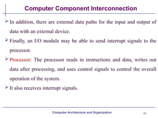
Inaddition, there are external data paths for the input and output of
data with an external device.
Finally, an I/O module may be able to send interrupt signals to the
processor.
Processor: The processor reads in instructions and data, writes out
data after processing, and uses control signals to control the overall
operation of the system.
It also receives interrupt signals.
Computer Architecture and Organization
42.
42
Computer Component Interconnection
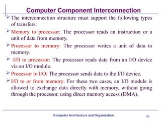
Theinterconnection structure must support the following types
of transfers:
Memory to processor: The processor reads an instruction or a
unit of data from memory.
Processor to memory: The processor writes a unit of data to
memory.
I/O to processor: The processor reads data from an I/O device
via an I/O module.
Processor to I/O: The processor sends data to the I/O device.
I/O to or from memory: For these two cases, an I/O module is
allowed to exchange data directly with memory, without going
through the processor, using direct memory access (DMA).
Computer Architecture and Organization
44
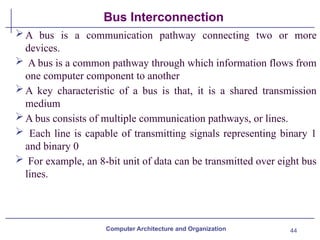
Bus Interconnection
A busis a communication pathway connecting two or more
devices.
A bus is a common pathway through which information flows from
one computer component to another
A key characteristic of a bus is that, it is a shared transmission
medium
A bus consists of multiple communication pathways, or lines.
Each line is capable of transmitting signals representing binary 1
and binary 0
For example, an 8-bit unit of data can be transmitted over eight bus
lines.
Computer Architecture and Organization
45.
45
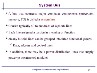
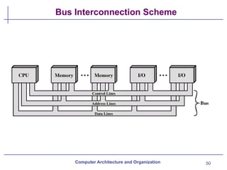
System Bus
A busthat connects major computer components (processor,
memory, I/O) is called a system bus
Consist typically 50 to hundreds of separate lines
Each line assigned a particular meaning or function
on any bus the lines can be grouped into three functional groups:
Data, address and control lines
In addition, there may be a power distribution lines that supply
power to the attached modules
Computer Architecture and Organization
46.
46
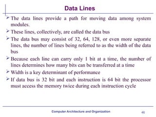
Data Lines
The datalines provide a path for moving data among system
modules.
These lines, collectively, are called the data bus
The data bus may consist of 32, 64, 128, or even more separate
lines, the number of lines being referred to as the width of the data
bus
Because each line can carry only 1 bit at a time, the number of
lines determines how many bits can be transferred at a time
Width is a key determinant of performance
If data bus is 32 bit and each instruction is 64 bit the processor
must access the memory twice during each instruction cycle
Computer Architecture and Organization
47.
47
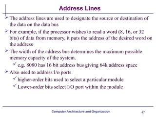
Address Lines
The addresslines are used to designate the source or destination of
the data on the data bus
For example, if the processor wishes to read a word (8, 16, or 32
bits) of data from memory, it puts the address of the desired word on
the address
The width of the address bus determines the maximum possible
memory capacity of the system.
e.g. 8080 has 16 bit address bus giving 64k address space
Also used to address I/o ports
higher-order bits used to select a particular module
Lower-order bits select I/O port within the module
Computer Architecture and Organization
48.
48
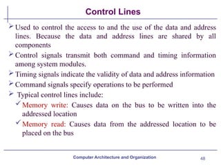
Control Lines
Used tocontrol the access to and the use of the data and address
lines. Because the data and address lines are shared by all
components
Control signals transmit both command and timing information
among system modules.
Timing signals indicate the validity of data and address information
Command signals specify operations to be performed
Typical control lines include:
Memory write: Causes data on the bus to be written into the
addressed location
Memory read: Causes data from the addressed location to be
placed on the bus
Computer Architecture and Organization
49.
49
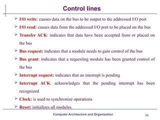
Control lines
I/Owrite: causes data on the bus to be output to the addressed I/O port
I/O read: causes data from the addressed I/O port to be placed on the bus
Transfer ACK: indicates that data have been accepted from or placed on
the bus
Bus request: indicates that a module needs to gain control of the bus
Bus grant: indicates that a requesting module has been granted control of
the bus
Interrupt request: indicates that an interrupt is pending
Interrupt ACK: acknowledges that the pending interrupt has been
recognized
Clock: is used to synchronize operations
Reset: initializes all modules.
Computer Architecture and Organization
52
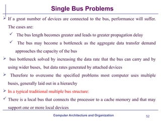
Single Bus Problems
If a great number of devices are connected to the bus, performance will suffer.
The cases are:
The bus length becomes greater and leads to greater propagation delay
The bus may become a bottleneck as the aggregate data transfer demand
approaches the capacity of the bus
bus bottleneck solved by increasing the data rate that the bus can carry and by
using wider buses, but data rates generated by attached devices
Therefore to overcome the specified problems most computer uses multiple
buses, generally laid out in a hierarchy
In a typical traditional multiple bus structure:
There is a local bus that connects the processor to a cache memory and that may
support one or more local devices
Computer Architecture and Organization
53.
53
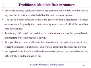
Traditional Multiple Busstructure
The cache memory controller connects the cache not only to this local bus, but to
a system bus to which are attached all of the main memory modules
The use of a cache structure insulates the processor from a requirement to access
main memory frequently thus, main memory can be moved off of the local bus
onto a system bus
In this way, I/O transfers to and from the main memory across the system bus do
not interfere with the processor’s activity
It is possible to connect I/O controllers directly onto the system bus but, A more
efficient solution is to make use of one or more expansion buses for this purpose
An expansion bus interface buffers data transfers between the system bus and the
I/O controllers on the expansion bus
Computer Architecture and Organization
54.
54
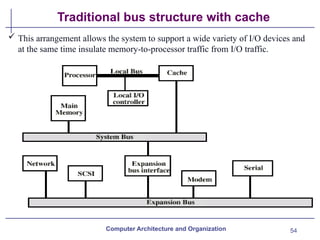
Traditional bus structurewith cache
Computer Architecture and Organization
This arrangement allows the system to support a wide variety of I/O devices and
at the same time insulate memory-to-processor traffic from I/O traffic.
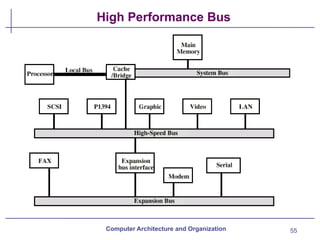
56
Bus Types
Computer Architectureand Organization
Dedicated Bus:A dedicated bus line is permanently assigned either
to one function or to a physical subset of computer components.
Has separate data & address lines
Common on many buses
The Advantages of Dedicated Bus is high throughput, because
there is less bus contention whereas it’s disadvantage is the
increased size and cost of the system.
However, dedicated bus is not essential because address and data
information may be transmitted over the same set of lines using an
Address Valid control line
57.
57
Bus Types
Computer Architectureand Organization
Mutiplexed Bus: A bus used as both address and data bus through
time multiplexing technique
The Advantages of multiplexed bus is use of fewer lines, which
saves space and, usually, cost.
Where as it’s disadvantages is more complex circuitry is needed
within each module and also causes a potential reduction in
performance
58.
58
Bus Arbitration
In allbut the simplest systems, more than one module may need
control of the bus
For example, an I/O module may need to read or write directly to
memory, without sending the data to the processor
some method of arbitration is needed because only one unit at a
time can successfully transmit over the bus
The various methods can be roughly classified as being either
centralized or distributed
Computer Architecture and Organization
59.
59
Centralised and Distributedbus Arbitration
In a centralized scheme, a single hardware device, referred to as a bus
controller or arbiter, is responsible for allocating time on the bus
The device may be a separate module or part of the processor
In a distributed scheme, there is no central controller. Rather, each
module contains access control logic and the modules act together to
share the bus
With both methods of arbitration, the purpose is to designate one
device, either the processor or an I/O module, as master
The master may then initiate a data transfer (e.g., read or write) with
some other device,
Computer Architecture and Organization
60.
Department of ComputerEngineering
End of Chapter 3
Computer Architecture
and Organization


![Lec4,5[1 of my believed jpuney that yu [w].ppt](https://cdn.slidesharecdn.com/ss_thumbnails/lec451-250412123010-403bbcb5-thumbnail.jpg?width=640&height=640&fit=bounds)