Logic gates are electronic components that perform basic logical operations like AND, OR, and NOT using binary inputs (0 and 1) to produce a single output.
Introduction To LogicGates
Logics Gates are the building blocks of digital circuit.
They performed basic logical function on binary inputs
(0 and 1).
4.
Basic Logic Gates
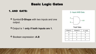
1.AND GATE:
Symbol:D-Shape with two inputs and one
output.
Output is 1 only if both inputs are 1.
Boolean expression :A.B
5.
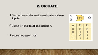
2. OR GATE
Symbol:curved shape with two inputs and one
inputs
Output is 1 if at least one input is 1.
Boolean expression : A.B
6.
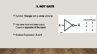
3. NOT GATE
Symbol: Triangle with a circle at the tip.
Has one input and one output.
Output is opposite of the input.
Boolean Expression: AorA`
7.
Universal Gates
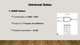
1. NANDGates:
Combination of AND + NOT
Output is 1 if inputs are different.
Boolean Expression: ~(A.B)
8.
2. NOR Gate
Combination of OR +NOT.
Output is 1 if both are 0.
Boolean Expression: ~(A+B)
9.
Exclusive Gate
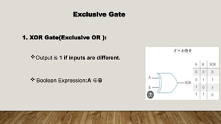
1. XORGate(Exclusive OR ):
Output is 1 if inputs are different.
Boolean Expression:A B
⊕
10.
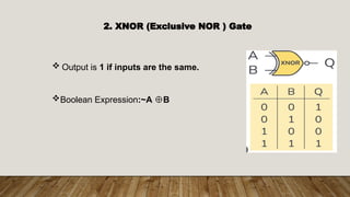
2. XNOR (ExclusiveNOR ) Gate
Output is 1 if inputs are the same.
Boolean Expression:~A B
⊕
11.
Applications of logicsgates
Uses.
Arithimatic logics unit.
Digital Electronics.
Computers.
Embedded Systems.
12.
Conclusion
Logic gates arethey basic building blocks of
digital circuits.They process binary inputs to
produce specific outputs ,helping run
devices like computers and calculators.