SlideShare a Scribd company logo
1 of 11
Download to read offline
International Journal of Engineering Science Invention
ISSN (Online): 2319 – 6734, ISSN (Print): 2319 – 6726
www.ijesi.org Volume 2 Issue 11ǁ November 2013 ǁ PP.20-30

Sequence Stratigraphic Interpretation of Kafe-1 Field, Offshore
Western Niger Delta, Nigeria
S. O. Obaje
Nigerian Geological Survey Agency, P.M.B. 1423, Fate, Ilorin, Kwara State, Nigeria

ABSTRACT: The area of study is located in Kafe-1 Field of the offshore western Niger Delta, Nigeria. The
principal aim of the paper is to present a sequence stratigraphic interpretation utilizing data sets from
biostratigraphic, well logs and seismic. Standard laboratory procedures were used for data treatment, while
computer software such as StrataBugs and GeoGraphix were used for data processing, integration and
interpretation. There are five wells studied in the area with the following distributions of sequences: Kafe-1-1
well (5 sequences), Kafe-1-2 (6 sequences), while Kafe-1-4, Kafe-1-5 and Kafe-1-6 wells have 4 sequences,
respectively. The candidate maximum flooding surfaces delineated with interpreted gamma ray and resistivity
well logs and seismic data were established using biostratigraphic data. Sequence stratigraphic interpretation
and correlation of the five wells were performed and the chart produced is useful in further deepening the
knowledge of the subsurface geology of the Niger Delta area of Nigeria.

KEYWORDS: Sequence stratigraphy, Kafe-1 Field, western Niger Delta, systems tract, well correlation
I.
INTRODUCTION
The area of study is located in Kafe-1 Field of the offshore western Niger Delta, Nigeria (Figs. 1 and
4). The Niger Delta is situated in the Gulf of Guinea on the west coast of Central Africa. Niger Delta lies
between latitudes 4° and 6° N and longitudes 3° and 9° E in the south-south geo-political region of Nigeria (Ojo
et al., 2009). The Cenozoic Niger Delta is situated at the intersection of the Benue Trough and the South
Atlantic Ocean where a triple junction developed during the separation of South America and Africa in the Late
Jurassic (Whiteman, 1982).
The scope and objectives of the research study involved the following:
 Identification of foraminifera and calcareous nannofossils and their abundance in the strata penetrated in the
wells.
 Utilization of biostatigraphic data to delineate candidate chronostratigraphical surfaces.
 Determination of the ages of the studied wells intervals.
 Drawing of the correlation chart for the wells in study area.
 Interpretation of well log signatures.
 Interpretation, utilization and integration of seismic data.
1.1

Literature Review
Three depositional cycles and lithostratigraphic subdivision of upper sandy continental Benin
Formation, intervening unit of alternating sandstones and shales (Agbada Formation) and lower shaly Akata
Formation have been identified in the Niger Delta area (Short & Staüble, 1967; Avbovbo, 1978, etc.). The
structural geology, sedimentology and petroleum geochemistry of the Niger Delta have been published by
several workers (Tuttle, et al., 1999; Weber & Daukoru, 1975, etc.). In addition, the biostratigraphy and
sequence stratigraphy of the Niger Delta have been studied (Ozumba, 1999; Adeniran, 1997; Petters, 1982, etc.).
However, in the published and unpublished works, integrated approach is lacking.
1.2

Geological Setting
Three main formations have been recognized in the subsurface of the Niger Delta (Short and Staüble,
1967; Weber and Daukoru, 1975; Avbovbo, 1978; Knox and Omatsola, 1989; Tuttle et al., 1999). These are the
Benin, Agbada and Akata Formations. These formations were deposited in continental, transitional and marine
environments, respectively; together they form a thick, overall progradational passive-margin wedge (Esan,
2002). The Akata Formation is the basal unit composed mainly of marine shales believed to be the main source
rock within the basin. The Agbada Formation is made up of alternating sandstone, siltstone and shale sequences

www.ijesi.org

20 | Page
Sequence Stratigraphic Interpretation…
that constitute the petroleum reservoirs of the basin. On the other hand, the Benin Formation largely consists of
non-marine sands with a few shaly intercalations (Esan, 2002).

Fig. 1. Index map of Niger Delta and location of study area (after Doust and Omatsola, 1990)

II.

SEQUENCE STRATIGRAPHY: PRINCIPLES AND CONCEPTS

1.1

Introduction
Sequence Stratigraphy is the study of genetically related facies within a framework of
chronostratigraphically significant surfaces (van Wagoner et al., 1990). Sedimentary facies is defined as the sum
total of the lithological and paleontological aspects of a stratigraphic unit in a particular place. The parameters
of facies are geometry, lithology, paleontology (including ichnofossils), sedimentary structures and paleocurrent
patterns (Reijers, 1996). Vertical facies analysis must be done within conformable strata packages to accurately
interpret coeval, lateral facies relationships along a single depositional surface. Walther’s Law states that a
vertical succession of facies, a facies sequence, reflects a similar lateral succession of facies, facies belts,
provided that the facies transitions are gradual (Reijers, 1996; Emery and Myers, 1997).There are three main
schools of thought on sequences, namely: Exxon school (1977-1988) based on unconformity, Galloway school
(1989) based on maximum flooding surfaces and Emery school (1993) based on subaerial unconformity and
transgression surfaces (Hart, 2005). Conversely, Hunt and Tucker model and Nummedal et al. model are
modifications of the above three models. Exxon School (1977-1988): The depositional sequence of the Exxon
model is based on highstand and lowstand systems tracts. It is bounded by subaerial unconformity, followed by
a regressive surface of marine erosion, and then a correlative conformity (which is often difficult to recognize).
The sequence begins with each highstand or progradation onto the shelf. The Exxon model has wide
acceptability and application in the hydrocarbon industry (Hart, 2005). Galloway School (1989): The Galloway
model of genetic stratigraphic sequences is based on sequences bounded by maximum flooding surfaces often
referred to as regressive-transgressive sequences (R-T). According to Hart (2005), the advantage of the genetic
stratigraphic model is that only one type of surface is defined, and this maximum flooding surface is easy to
identify. However, Hart (2005) warned that in the genetic sequence model, an interpreter should note the
possibility of unconformities lying within the sequences. Emery School (1993): The Emery school is also
referred to as the Emery and Johannessen model of transgressive-regressive (T-R) sequences. In this model,
sequences are bounded by subaerial unconformities and maximum regressive surfaces. There are two systems
tracts in the T-R sequence model. The transgressive systems tract lies between the sequence boundary at the
base and the maximum flooding surface at the top. The regressive systems tract lies between the maximum
flooding surface at the base and the sequence boundary at the top. The T-R is newest concept and it is simple to
apply, but not widely used (Hart, 2005).
Depositional sequence is the basic stratigraphic unit of sequence stratigraphy. A sequence is defined as
a relatively conformable succession of genetically related strata bounded by unconformities or their correlative
conformities (Vail et al., 1977; van Wagoner et al., 1990, etc.). Sequences can be subdivided into systems tracts,
which are linkages of contemporaneous depositional systems (van Wagoner et al., 1990; Hart, 2005, etc.). These
include lowstand, transgressive, highstand and shelf margin systems tracts, respectively. Each systems tract is
deposited at a predictable position in an interpreted eustatic cycle, and has recognizable signatures in well logs
and seismic data (Vail et al., 1977; van Wagoner et al., 1990, etc.).

www.ijesi.org

21 | Page
Sequence Stratigraphic Interpretation…
Sequences and systems tracts can be defined on the basis of strata geometry and physical relationships.
Fundamental recognition criteria for sequences include definition of sequence boundaries (unconformities or
their correlative conformities) and vertical relationships and facies of systems tracts within the sequences.

III.

MATERIALS AND METHODS

The five wells in the study area are Kafe-1-1, Kafe-1-2, Kafe1-4, Kafe-1-5 and Kafe-1-6. Ditch
cuttings sampled at 18.29 meter intervals were given for the five wells in Kafe-1 Field. The standard
micropaleontological preparation technique for foraminiferal samples and calcareous nannofosils were used in
the Laboratory. The statistical data of the specimens were recorded and StrataBugs software was used for data
processing and integration with the well logs data, which were given in LAS format. Other materials for the
study are seismic section, well logs, base map and check shot data for five wells in the study area. The 3D
seismic volume data supplied in SEG-Y format were loaded on Landmark Workstation. The database was
created on the GeoGraphix Discovery R2007.1 platform (Windows) version. The study was performed using
SeisVision 3Dimensional (3D) seismic interpretation modules. The following method and workflow plan was
adopted: loading of seismic and well data, review of seismic and log data after loading, integration of
biostratigraphic data and their calibration with seismic data, identification of candidate sequence boundaries,
and the posting of the dominant faults on the transect. The time-depth relationship was determined using the
check shot data available for Kafe-1-1 well (Fig. 2). The two-way time (TWT) is given in milliseconds (msec.)
on the x-axis, while the true vertical well depth is given on the y-axis in feet (and the conversion value is 1 foot
equals 0.304804 meter). The data sets for this study were given by ChevronTexacco Nigeria Limited and the
author is deeply grateful.

Fig. 2. The Plot of Check Shot Chart for Kafe-1-1 Well (Conversion: 1 foot = 0.304804 metre)

IV.

SEQUENCE STRATIGRAPHIC INTERPRETATION OF KAFE-1 FIELD

The absolute ages of the foraminiferal and calcareous nannofossil biozones, sequence boundaries and
the third order maximum flooding surfaces were based on correlation zones and cycles of several authors such
as Blow (1969, 1979), Martini (1971), Borsetti et al. (1979), Iaccarino and Salvatorino (1982), Iaccarino (1985),
Berggren et al. (1985), Bolli et al. (1987), Adeniran (1997), Ozumba (1999).The sequence stratigraphic
approach of Vail and Wornardt (1990) was employed in this study. The following procedures were used;
(a)
High-resolution biostratigraphy and paleoecologic zonations using foraminifera and calcareous
nannofossils. The foraminiferal and calcareous nannofossil biozonations were correlated to the
magnetobiostratigraphic schemes of Berggren et al. (1985) and Martini (1971).
(b)
Interpretation of well log responses (gamma-ray and resistivity logs) was confirmed with ditch cutting
characteristics of sediments assessed using stereo-binocular microscopy. The well log patterns were
used to delineate the sequences to different kinds of systems tracts (Fig. 4). The identified sequence
boundaries were found at inflection of progradation to retrogradation of parasequences in a shallowing
upward sand unit, and also at the inflection of the lowstand prograding complexes (lowstand systems
tract). The higher gamma ray and lowest resistivity readings were used to identify maximum flooding
surfaces (Vail and Wornardt, 1990).
(c)
From the faunal and floral abundance/diversity peaks (using the first and last down-hole occurrences),
four maximum flooding surfaces dated 12.8 Ma, 11.5 Ma, 10.4 Ma and 9.5 Ma, and five sequence
boundaries dated 13.1 Ma, 12.1 Ma, 10.6 Ma, 10.35 Ma and 8.5 Ma, respectively, were recognized. The
fluctuation in specimens abundances have been established to reflect specimens’ migration that has been
linked to eustatic changes in sea level (Adegoke, 2002; Vail and Wornardt, 1990).

www.ijesi.org

22 | Page
Sequence Stratigraphic Interpretation…
4.1

KAFE-1-1 WELL
Five sequences have been recognized in this well (Fig. 4).

Sequence I (3,313.48 – 3,791.71 m)
In this sequence, the lowstand systems tract was not penetrated. The transgressive systems tract (TST:
3,446.37 - 3,791.71 m) is made up of retrogradational stacking pattern of interbedded clay, shale, mudstone,
silty mudstone, argillaceous siltstone and single unit of 7.62 m thick sandstone (fine - medium grained texture)
at 3,589.02 m. The transgressive systems tract thinned into a major condensed section (MFS, 12.8 Ma) indicated
by the abundance peaks of FDO: Cassidulina neocarinata (THALMANN) at depth of 3,446.37 m. The
highstand systems tract (HST: 3,313.48 – 3,446.37 m) is made up of shale/mudstone prograding to argillaceous
siltstone that changed to aggradational unit of sandy mudstone interbedded by thinly bedded fine - medium
grained sandstone of about 3.81 m thickness. The highstand systems tract is terminated at the top by sequence
boundary (SB: 12.1 Ma) at 3,313.48 m depth, which is defined at the point of inflection in the stacking pattern
from net coarsening upwards to net fining upwards. The noticed abrupt change in the gamma ray log signature
indicated an erosional truncation that defined the aforementioned sequence boundary.
4.1.1

4.1.2

Sequence II (3,046.17 - 3,313.48 m)
This sequence is mainly made up of transgressive systems tract and highstand systems tract. The
transgressive systems tract (TST: 3,150.41 - 3,313.48 m) is made up of two lithological units of lower
argillaceous sandstone underlying sandy mudstone. The stacking pattern is retrogradational with upward fining
units with low blocky to serrated well log patterns. The abrupt change of the well log signature coupled with
major faunal/floral abundance peaks are indicative of maximum flooding surface (MFS: 11.5 Ma) at 3,150.41
m. The MFS is dated by the FDO: Globorotalia obesa (BOLLI) marker fossil. The highstand systems tract
(HST: 3,046.17 – 3,150.41 m) is made up of aggradational stacking pattern of two sandy units. At the sequence
boundary (SB: 10.6 Ma) at 3,046.17 m, the sandy mudstone unit changed from aggradational to retrogradational
stacking pattern.
4.1.3

Sequence III (2,639.57 - 3,046.17 m)
This sequence is made up of transgressive systems tract and highstand systems tract. At the sequence
boundary (SB: 10.6 Ma at 3,046.17 m) indicated by the abrupt change of the well signature and faunal/floral
abundance/diversity minor peaks, the sandy unit of the highstand systems tract of the previous sequence
abruptly changed from aggradational to retrogradational stacking pattern. The transgressive systems tract (TST:
2,731.31 - 3,046.17 m) is made up of units of sandstones interbedded by thinly bedded shales. The sandstone
units are individually aggradational with fining upward stacking pattern towards the maximum flooding surface
(MFS: 10.4 Ma) at 2,731.31 m depth. The highstand systems tract (HST: 2,639.57 - 2,731.31 m) is made up of
two sandy units interbedded by thinly bedded shale intercalations. The HST is dominantly made up of
aggradational stacking pattern of two sandy units. The net fining upward pattern is noticed and the wireline log
signature and seismic section signify an erosional truncation that defined the sequence boundary (SB: 10.35 Ma)
at 2,639.57 m depth.
4.1.4

Sequence IV (2,268.93 - 2,639.57 m)
This sequence is made up of three systems tracts, namely: transgressive systems tract, highstand
systems tract, and lowstand systems tract (lowstand prograding complex). The transgressive systems tract (TST:
2,431.39 - 2,639.57 m) is made up of fining upward retrogradational stacking pattern of sandy units interbedded
by thinly bedded shales. The maximum flooding surface (MFS: 9.5 Ma) is defined at the top of the transgressive
systems tract at depth of 2,431.39 m with shaly condensed section defined by FDO: Uvigerina sparsicostata
(CUSHMAN & LAIMING) and Discoaster hamatus (MARTINI & BRAMLETTE). The highstand systems
tract (HST: 2,268.93 - 2,431.39 m) is made up of two units of sand interbedded by shale and argillaceous
siltstone. The HST is dominantly made up of aggradational stacking pattern of two sandy units which fines to
the top into an erosional truncation that defined the sequence boundary (SB: 8.5 Ma) at depth of 2,268.93 m.
The highstand systems tract argillaceous siltstone with fining upward stacking pattern changed to coarsening
upward pattern of the sandstone unit of the overlying lowstand prograding complex.
4.1.5

Sequence V (1,527.05 - 2,268.93 m)
This sequence is made up only of the lowstand prograding complex. It is dominantly made up of
continental sandstone interbedded by sequences of mixed sandstones (70% coarse grained), siltstones,
mudstones, shales and clays. The lithofacies is referred to as the Benin Formation. The interval (1,527.05 -

www.ijesi.org

23 | Page
Sequence Stratigraphic Interpretation…
2,268.93 m) is barren of fossils. The well log signature pattern is serrated shaped with coarsening upward
stacking pattern.
4.2

Kafe-1-2 Well
This well has six sequences (Fig. 4).

Sequence I (3,441.80 – 3,781.71 m)
In this sequence only the highstand systems tract was penetrated via drilling. The wireline log readings
are suppressed, thus the stacking pattern is not obvious. The point of change in the stacking pattern delineates
the sequence boundary (SB: 13.1 Ma) at 3,441.80 m depth. The 13.1 Ma SB is dated with R. pseudoumbilicus (>
7µm) (GARTNER) and Cyclicargolithus floridanus (ROTH & HAY).
4.2.1

4.2.2

Sequence II (3,386.94 - 3,441.80 m)
The sequence is made up of transgressive systems tract and highstand systems tract. The transgressive
systems tract (TST: 3,404.92 - 3,441.80 m) has retrogradational stacking pattern and it is capped by MFS, 12.8
Ma at depth of 3,404.92 m. The MFS is defined by marker fossil, Globigerinoides subquadratus
(BRÖNNIMANN). The highstand systems tract (HST: 3,386.94 - 3,404.92 m) is made up of a single unit of
sandy mudstone with aggradational stacking pattern. The point of transition of aggradational to progradational
was used to define the sequence boundary (SB: 12.1 Ma) dated with FDO: Calcidiscus premacintyrei
(THEODORIDIS) and H. stalis (THEODORIDIS) at depth of 3,386.94 m.
4.2.3

Sequence III (3,157.12 - 3,386.94 m)
The sequence is made up of transgressive systems tract and highstand systems tract. The transgressive
systems tract (TST: 3,218.08 - 3,386.94 m) is made up of four sandy units, which are retrogradational. The
transgressive systems tract is capped by MFS, 11.5 Ma dated with FDO: Discoaster bellus (BUKRY &
PERCIVAL), S. moriformis (BRÖNNIMANN & STRADNER), LDO of Catinaster coalitus (MARTINI &
BRAMLETTE), FDO: Spirosigmoilina oligoceanica (CUSHMAN), Globorotalia obesa (BOLLI), LDO:
Globorotalia continuosa (BLOW) and Globorotalia mayeri (CUSHMAN & ELLISOR). The highstand systems
tract (HST: 3,157.12 - 3,218.08 m) is made up of a single sandy unit that has aggradational stacking pattern. At
the top of the HST, the sandy unit fines into shaly unit and there is an abrupt change of the gamma ray log
signature indicating erosional truncation, which defines the sequence boundary (SB: 10.6 Ma) at depth of
3,157.12 m.
4.2.4

Sequence IV (2,855.06 - 3,157.12 m)
This sequence is made up of 3 systems tracts, namely: lowstand systems tract (lowstand prograding
complex), transgressive systems tract and highstand systems tract. The lowstand prograding complex (PGC:
2,907.79 - 3,157.12 m) lies immediately above the 10.6 Ma SB. It is made up of five sandy units interbedded by
thin shale intercalations. The PGC has coarsening upward stacking pattern. The transgressive systems tract
(TST: 2,882.80 - 2,907.79 m) has retrogradational stacking pattern. The thin sandy unit (7.62 m thickness) in the
TST fines upward and changed into shaly condensed section defining the maximum flooding surface (MFS:
10.4 Ma) at depth of 2,882.80 m. The highstand systems tract (HST: 2,855.06 - 2,882.80 m) is made up of
aggradational stacking pattern that fines upward to the sequence boundary (SB: 10.35 Ma) at depth of 2,855.06
m. The 10.35 Ma sequence boundary was characterised by the LDO of D. hamatus (MARTINI &
BRAMLETTE) and the associated markers are Catinaster calyculus (MARTINI & BRAMLETTE), R. haqii
(BACKMAN), R. pseudoumbilicus (medium, 3-5 µm) (GARTNER).
4.2.5

Sequence V (2,420.11 - 2,855.06 m)
The sequence is made up of 3 systems tracts, viz: lowstand systems tract (PGC), transgressive systems
tract and highstand systems tract. The lowstand prograding complex (PGC: 2,471.32 - 2,420.11 m) has nine
sandy units separated by thinly bedded shales. The PGC has coarsening upward stacking pattern. The upper
sandy units fine upward into a shaly unit that forms a condensed section defining the transgressive surface. The
transgressive systems tract (TST: 2,431.39 - 2,471.32 m) has a single unit of fining upward retrogradational
stacking pattern that is capped by maximum flooding surfaces (MFS: 9.5 Ma) at depth of 2,431.39 m. The 9.5
Ma MFS is dated with the FDO of D. hamatus (MARTINI & BRAMLETTE) and ACME: Sphenolithus abies
(DEFLANDRE) and LDO Globigerinoides extremus (BOLLI & BERMUDEZ). The associated markers are
Catinaster mexicanus (BUKRY), D. pentaradiatus (TAN), H. carteri (WALLICH), Uvigerina sparsicostata
(CUSHMAN & LAIMING) and Globorotalia obesa (BOLLI). The highstand systems tract (HST: 2,420.11 2,431.39 m) is made up of a single unit of sandy mudstone with an overall aggradational stacking pattern. It

www.ijesi.org

24 | Page
Sequence Stratigraphic Interpretation…
fines upward to a sequence boundary (SB: 8.5 Ma) at 2,420.11 m depth. The 8.5 Ma sequence boundary is dated
with the LDO: D. quinqueramus (GARTNER) and the associated marker species are R. haqii (BACKMAN), D.
braarudii (BUKRY), Coccolithus pelagicus (WALLICH), D. pentaradiatus (TAN), S. abies (DEFLANDRE),
H. carteri (WALLICH), U. jafari (MÜLLER) and U. rotula (KAMPTNER).
4.2.6

Sequence VI (1,527.05 - 2,420.11 m)
This sequence is made up of only lowstand systems tract (PGC). The lowstand prograding complex is
characterised by serrated “saw-shaped” gamma ray log signature, which is indicative of sandstones interbedded
by thinly bedded shale intercalations. The sequence is barren in fossils and it is called the Benin Formation.
There is a fault between Kafe-1-1 and Kafe-1-2 wells. The down-thrown side of the recognized growth fault is
located at Kafe-1-2 well area, while the up-thrown side is at the Kafe-1-1 area.
4.3

Kafe-1-4 Well
This well has four sequences (Fig. 4).
4.3.1
Sequence I (3,404.62 – 3,493.01 m)
This sequence is relatively short and it is dominantly made up of shales with sandy intercalation. The
net composition of the ratio of sandstones to shales is about 10%:90%. The sequence is incomplete because the
drilling in the well penetrated only the transgressive systems tract at the given depth. It has retrogradational
stacking pattern, which is capped by sequence boundary (SB: 12.1 Ma) at depth of 3,404.62 m. The 12.1 Ma
sequence boundary is dated with the FDO: Calcidiscus premacintyeri (THEODORIDIS) and the associated
fossil marker is H. stalis (THEODORIDIS). On the other hand, it may be inferred that the highstand systems
tract in this sequence may have been completely eroded leaving behind an erosional truncation that defined the
aforementioned sequence boundary at 2,535 to 2,752 microseconds in the seismic sections.
4.3.2

Sequence II (3,157.42 - 3,404.62 m)
This sequence is made up of two systems tracts, namely: the transgressive systems tract and the
highstand systems tract. The transgressive systems tract (TST: 3,219.00 - 3,404.62 m) is made up of two sandy
units interbedded by argillaceous siltstone and shales. The transgressive systems tract has an overall
retrogradational stacking pattern. The lower sandy unit coarsens upward, while the upper sandy unit though
initially coarsened, it latter fines upward into a condensed section of shale unit forming the maximum flooding
surface (MFS: 11.5 Ma) at depth of 3,219.00 m. The 11.5 Ma MFS is dated with the FDO: Spirosigmoilina
oligoceanica (CUSHMAN). The highstand systems tract (HST: 3,157.42 - 3,219.00 m) is made up of a single
unit of argillaceous sandstone bounded at top and base by shales. The well log signature shows a fining upward
stacking pattern. There is an abrupt change at the point of inflection that defines the sequence boundary (SB:
10.6 Ma) at depth of 3,157.42 m.
4.3.3

Sequence III (2,433.22 - 3,157.42 m)
This sequence has three systems tracts, namely: lowstand systems tract, transgressive systems tract and
highstand systems tract. The lowstand systems tract is present as lowstand prograding complex (PGC). The
PGC is found at the depth interval of 2,727.96 – 3,157.42 m. It has an inverted Christmas tree-shaped well log
signature. It is made up of four sandy units in which the lower sandy body fines upward while the middle sandy
body coarsens upward. On the other hand, the upper sandy bodies fine into shaly condensed unit, which defines
the transgressive surface. The transgressive systems tract (TST: 2,433.22 - 2,727.96 m) is composed of seven
sandy units that are separated by thinly bedded shale intercalations. The transgressive systems tract has
retrogradational stacking pattern, however, three sandy units within it have individually coarsening upward
aggradational units. The upper sandy body fines upward into a major condensed shale unit, which defines the
maximum flooding surface (MFS: 10.4 Ma) at depth of 2,433.22 m. The 10.4 Ma MFS is dated with the ACME
of D. hamatus (MARTINI & BRAMLETTE) and the associated marker fossils are R. haqii (BACKMAN), R.
pseudoumbilicus (medium 3-5 µm) (GARTNER) and the LDO of Catinaster calyculus (MARTINI &
BRAMLETTE).
The highstand systems tract (HST: 2,273.81 - 2,433.22 m) is made up of two sandy units of about
45.72 – 76.20 m thickness and they are interbedded by thinly bedded shales. The earlier sandy unit has
aggradational stacking pattern, while the latter unit has progradational stacking pattern. The top of the HST fines
upward into a shaly unit, which defines the sequence boundary (SB: 10.35 Ma) at depth of 2,273.81 m. The
10.35 Ma sequence boundary is dated with the LDO of Discoaster hamatus (MARTINI & BRAMLETTE).

www.ijesi.org

25 | Page
Sequence Stratigraphic Interpretation…
4.3.4

Sequence IV (731.52 - 2,273.81 m)
This sequence is made up mainly of lowstand systems tract (PGC). The lowstand prograding complex
(PGC: 731.52 - 2,273.81 m) is composed of thirteen units of medium to coarse grained sandstones that are
interbedded by argillaceous siltstones, siltstones, clays, mudstones, shales, etc. This PGC is non-marine and it is
barren of fossils. It constitutes the set of lithofacies that form the Benin Formation. It is of continental fluviatile
environment of deposition. There is fault between Kafe-1-2 and Kafe-1-4 wells. The down-thrown side of the
recognized growth fault is located at the Kafe-1-4 well area, while the up-thrown side is at the Kafe-1-2 well
area (Fig.3).
4.4

Kafe-1-5 Well
Four sequences were recognized in this well (Fig. 4).
4.4.1
Sequence I (3,387.24 - 3,535.68 m)
Two systems tracts were penetrated in this well; they are the transgressive systems tract and the highstand
systems tract. The transgressive systems tract (TST: 3,466.80 - 3,535.68 m) is composed mainly of shales,
which fines upward in a retrogradational stacking pattern. The transgressive systems tract is capped by
maximum flooding surface (MFS: 12.8 Ma) at depth of 3,466.80 m. The 12.8 Ma MFS is dated with the FDO of
Globigerinoides subquadratus (BRÖNNIMANN). The highstand systems tract (HST: 3,387.24 - 3,466.80 m) is
composed mainly of sandy mudstone interbedded by thin argillaceous siltstone of about 7.62 m thickness. The
highstand systems tract has fining upward stacking pattern. It is truncated at the top by an erosional surface,
which defines the sequence boundary (SB: 12.1 Ma) at depth of 3,387.24 m. At the point of inflection, there is
an abrupt change in the stacking pattern from net fining upward to a net coarsening upward stacking pattern.
0

500

1,000

Msec
1,500

Growth faults

SB 8.5 Ma
MFS 9.5 Ma
SB 10.35 Ma
MFS 10.4 Ma
SB 10.6 Ma
MFS 11.5 Ma
SB 12.1 Ma
MFS 12.8 Ma

2,000

2,500

3,000

3,500

Fig. 3. Structures with growth faults along cross-line (strike) 1,600 [Scale: vertical: 100 msec.; horizontal: 10
strike lines]
4.4.2
Sequence II (2,909.93 – 3,387.24 m)
This sequence has three systems tracts, namely: lowstand prograding complex, transgressive and
highstand systems tracts, respectively. The lowstand prograding complex (PGC: 2,956.56 - 3,387.24 m) is made
up of six fine to medium grained sandy units that range in thickness from about 15.24 - 106.68 m. Thin beds of
shales and argillaceous siltstones of about 15.24 - 48.77 m thickness separate the sandstone units, respectively.
The lower sandstone units are downlap, progradational, while the upper units are toplap with aggradational
stacking pattern. These sandy units coarsen upward but at the top, they fine upward into shaly unit, which
defines the transgressive surface at depth of 2,956.56 m. The transgressive systems tract (TST: 2,933.10 2,956.56 m) is composed of a set of backstepping parasequences of shales. It begins with the transgressive
surface, which is the first and minor marine flooding surface above the lowstand prograding complex. The
transgressive systems tract backsteps until the point of maximum marine transgression was reached. It is capped
by a major marine flooding surface (MFS: 11.5 Ma) at depth of 2,933.10 m. The 11.5 Ma MFS is dated with the
FDO: Globorotalia obesa (BOLLI) and Globorotalia foshi lobata (BERMUDEZ). The highstand systems tract

www.ijesi.org

26 | Page
Sequence Stratigraphic Interpretation…
(HST: 2,909.93 - 2,933.10 m) is composed of shales with fining upward stacking pattern. There is an abrupt
change in the gamma ray log signature indicating an erosional truncation that defines the sequence boundary
(SB: 10.6 Ma) at depth of 2,909.93 m.
4.4.3

Sequence III (2,417.98 - 2,909.93 m)
This sequence has three systems tracts, namely: lowstand prograding complex, transgressive and
highstand systems tracts, respectively. The lowstand prograding complex (PGC: 2,575.56 - 2,909.93 m) is made
up of four sandy units separated by shaly intercalations. The lower unit is composed of coarse grained
sandstones with 83.82 m thickness and overlain by shales with 114.30 m thickness serving as very good
reservoir seal. Shales of 7.62 m to 30.48 m thickness interbed the other sandy units, which have thicknesses in
range of 30.48 - 91.44 m, respectively. The PGC has net coarsening upward stacking pattern that looks like
“inverted Christmas tree” shape in the gamma ray log. There is an abrupt change in the gamma ray log signature
signifying transgressive surface at depth of 2,575.56 m.
The transgressive systems tract (TST: 2,443.89 - 2,575.56 m) is composed of four units of sands
(7.62 - 30.48 m thickness) overlain by shales, which may form good stratigraphic seal over the reservoir sands.
Though the overall stacking pattern is retrogradational, the gamma ray log signature indicates that the lower
sandy units have individual coarsening upward stacking pattern, while the upper sandy units fine upward into a
shaly unit, which defines the major marine flooding surface (MFS: 10.4 Ma) at depth of 2,443.89 m. The 10.4
Ma MFS is dated by the ACME of D. hamatus (MARTINI & BRAMLETTE) and the associated marker fossils
are R. pseudoumbilicus (medium 3-5 µm) (GARTNER) and the LDO of Catinaster calyculus (MARTINI &
BRAMLETTE). The highstand systems tract (HST: 2,417.98 - 2,443.89 m) is composed of marine shales with
fining upward retrogradational stacking pattern. It fines into sandy siltstone at an inflection point marking the
sequence boundary (SB: 10.35 Ma) at depth of 2,417.98 m. The 10.35 Ma SB is dated by the LDO of D.
hamatus (MARTINI & BRAMLETTE) and the associated marker fossils are Catinaster calyculus (MARTINI &
BRAMLETTE), Reticulofenestra haqii (BACKMAN), R. pseudoumbilicus (medium 3-5 µm) (GARTNER).
4.4.4

Sequence IV (1,219.20 - 2,417.98 m)
This sequence is principally composed of the lowstand prograding complex (PGC). The PGC is made
up of ten sandy units, which are separated to two distinct lithological units on the basis of their environments of
deposition. The lower part is made up of two sandy units of 30.48 m thick sandstones interbedded by sandy
siltstone at the base and shales at the top. This lower part forms the upper part of the fossiliferous Agbada
Formation at depths of 2,273.81 - 2,417.98 m. On the other hand, the upper part is made up of eight sandy units
that are medium to coarse grained in texture. These sandy units have 30.48 - 228.60 m thickness and separated
by thinly bedded argillaceous siltstones, mudstones, clays and shales. It is non-marine, barren in fossils, and
forms the upper part that constitutes the Benin Formation at depths of 1,219.20 - 2,273.81 m.
4.5

Kafe-1-6 Well
Four sequences were recognized in Kafe-1-6 well (Fig. 4).

4.5.1

Sequence I (3,845.05 - 3,962.40 m)
In this sequence, two systems tracts were penetrated in this well. The systems tracts are the
transgressive and highstand systems tracts. The transgressive systems tract (TST: 3,907.23 - 3,962.40 m) is
composed of two sandy units of 7.72 - 30.48 m thickness separated by 3.05 - 21.34 m thick shale intercalations.
The units have an overall retrogradational stacking pattern. The upper argillaceous sandstone unit fines into a
condensed section of shaly unit, which defines the maximum flooding surface (MFS: 12.8 Ma) at depth of
3,907.23 m. The 12.8 Ma MFS is dated with Rectoglandulina comatula (LOEBLICH & TAPPAN) fossil
marker.
The highstand systems tract (HST: 3,845.05 - 3,907.23 m) is mainly composed of hemi-pelagic
shales/mudstones. The overall stacking pattern is aggradational and fines upward with an abrupt change of the
gamma ray log signature signifying an erosional truncation that defines the sequence boundary (SB: 12.1 Ma) at
depth of 3,845.05 m. The 12.1 Ma sequence boundary is dated with FDO of Calcidiscus premacintyrei
(THEODORIDIS) and the associated fossil marker is H. stalis (THEODORIDIS).
4.5.2

Sequence II (3,592.37 - 3,845.05 m)
This sequence has two systems tracts, namely: transgressive and highstand systems tracts. The
transgressive systems tract (TST: 3,622.55 - 3,845.05 m) is composed of two units of an underlying argillaceous
sandstone that is overlain by shales. The gamma ray log signature shows a retrogradational stacking pattern. The

www.ijesi.org

27 | Page
Sequence Stratigraphic Interpretation…
argillaceous sandy unit fines upwardly into shaly condensed section that defines a maximum flooding surface
(MFS: 11.5 Ma) at depth of 3,622.55 m. The 11.5 Ma MFS is dated with the FDO of Globorotalia mayeri
(CUSHMAN & ELLISOR) and the associated fossil marker is LDO: Globorotalia continuosa (BLOW).
The highstand systems tract (HST: 3,592.37 - 3,622.55 m) is composed mainly of shales that fines upwardly and
progrades into an erosional truncation that defines a sequence boundary (SB: 10.6 Ma) at depth of 3,592.37 m.
The 10.6 Ma sequence boundary is dated with the LDO of D. hamatus (MARTINI & BRAMLETTE) and the
FDO of Catinaster coalitus (MARTINI & BRAMLETTE) and the associated fossil markers are D. bellus
(BUKRY & PERCIVAL), U. jafari (KAMPTNER) and D. bollii (MARTINI & BRAMLETTE).
Sequence III (2,948.33 – 3,592.37 m)
Three systems tracts were recognized in this sequence. These are the lowstand prograding complex,
transgressive and highstand systems tracts. The lowstand prograding complex (PGC: 3,314.70 - 3,592.37 m) is
composed of six sandy units, which are individually interbedded by shales. The overall stacking pattern is
aggradational, and coarsens upward. A shaly condensed section that defines the transgressive surface caps the
upper sandy unit. The gamma ray log signature also indicates abrupt change from very low value of 20 API to
very high value of 125 API, signifying the presence of transgressive surface at depth of 3,314.70 m. The
transgressive systems tract (TST: 3,258.01 - 3,314.70 m) is made up of marine shales with retrogradational
stacking pattern and fines upwardly to a maximum flooding surface (MFS: 10.4 Ma) at depth of 3,258.01 m.
The 10.4 Ma MFS is dated with the ACME of D. hamatus (MARTINI & BRAMLETTE) and the associated
marker fossils are R. haqii (BACKMAN), R. pseudoumbilicus (medium 3 - 5µm) (GARTNER) and the FDO of
Catinaster calyculus (MARTINI & BRAMLETTE). The shales of the transgressive systems tract may form
good seal for the reservoir sands of the underlying PGC. The highstand systems tract (HST: 2,948.33 - 3,258.01
m) is composed of six sandy units. The lower earlier units, at depths of 3,133.34 - 3,238.50 m, have
aggradational stacking pattern and coarsen upward. On the other hand, the upper later units have progradational
stacking pattern and capped by shaly unit that fines into the erosional truncation, which defines the sequence
boundary (SB: 10.35 Ma) at depth of 2,948.33 m. The 10.35 Ma sequence boundary was dated with the LDO of
D. hamatus (MARTINI & BRAMLETTE) and the associated marker fossils are Catinaster calyculus
(MARTINI & BRAMLETTE), Reticulofenestra haqii (GARTNER) and R. pseudoumbilicus (medium 3-5 µm)
(GARTNER).
4.5.3

4.5.4

Sequence IV (1,222.25 - 2,948.33 m)
This sequence is made up of lowstand prograding complex. The PGC has two units, namely: marine
and non-marine units, respectively. The marine unit, found at depths of 2,301.24 - 2,948.33 m, is made up of
sandy units separated by argillaceous siltstones, mudstones, clays and shales that contain fossils. This constitutes
the upper part of the Agbada Formation. On the other hand, the non-marine unit is made up of medium to very
coarse-grained, thickly bedded sandstones with 15.24 - 152.40 m thickness that are interbedded by thinly
bedded argillaceous siltstones, mudstones, clays and shales. This unit (at depth of 1,222.25 - 2,301.24 m) barren
of fossils, is of the continental, fluviatile depositional environment and it constitutes the Benin Formation.
V.
CONCLUSION
The aim and objectives of the study were achieved. Several workers have carried out researches into
many aspects of the geology, sedimentology, geochemistry, biostratigraphy, seismic stratigraphy and sequence
stratigraphy of the Niger Delta area of Nigeria; however, most of the published and unpublished works lack
integrated approach to the sequence stratigraphic interpretation.
Moreover, the principles and concepts of sequence stratigraphy and the prevailing schools of thought
on the subject were discussed. Nevertheless, the discussion on the merit or demerit of the various approaches to
sequence stratigraphy was avoided because it is outside the scope of this paper. The interpretation of well log
responses (gamma-ray and resistivity logs) was confirmed with ditch cutting characteristics of sediments
assessed using stereo-binocular microscopy. The well log patterns were used to delineate the sequences to
different kinds of systems tracts. The identified sequence boundaries were found at the inflection of
progradation to retrogradation of parasequences in a shallowing upward sand unit, and also at the inflection of
the lowstand prograding complexes (lowstand systems tract). The higher gamma ray and lowest resistivity
readings were used to identify maximum flooding surfaces, which were further established with biostratigraphic
data. There are five wells studied in the area. From the faunal and floral abundance/diversity peaks (using the
first and last down-hole occurrences), four maximum flooding surfaces dated 12.8 Ma, 11.5 Ma, 10.4 Ma and
9.5 Ma, and five sequence boundaries dated 13.1 Ma, 12.1 Ma, 10.6 Ma, 10.35 Ma and 8.5 Ma, respectively,
were recognized. The fluctuation in specimens abundances have been established to reflect specimens’
migration that has been linked to eustatic changes in sea level. There is a fault between Kafe-1-1 and Kafe-1-2

www.ijesi.org

28 | Page
Sequence Stratigraphic Interpretation…
wells. The down-thrown side of the recognized growth fault is located at Kafe-1-2 well area, while the upthrown side is at the Kafe-1-1 well area. In addition, there is another growth fault between Kafe-1-2 and Kafe-14 wells. The down-thrown side of this growth fault is located at the Kafe-1-4 well area, while the up-thrown side
is at the Kafe-1-2 well area. Erosional truncation and downlap surfaces were prominent structures mapped in
the seismic sections for sequence stratigraphic interpretation of the studied wells. The wells were drilled to the
depths of 3,782.57 m (Kafe-1-1), 3,791.71 m (Kafe-1-2), 3,489.96 m (Kafe-1-4), 3,535.68 m (Kafe-1-5) and
3,962.40 m (Kafe-1-6).

REFERENCES
[1].
[2].
[3].
[4].

[5].
[6].
[7].
[8].
[9].
[10].
[11].
[12].

[13].
[14].
[15].

[16].
[17].
[18].
[19].
[20].
[21].
[22].
[23].

[24].

[25].

[26].
[27].

Adegoke, O.S. (2002): High resolution biostratigraphy, sequence stratigraphy, 3-D modeling: indispensable tools for E & P
activities in the new millennium. NAPE Bulletin vol. 16, no. 1, pp. 46 – 65.
Adeniran, B.V., 1997. Quantitative Neogene planktonic foraminiferal biostratigraphy of western Niger Delta, Nigeria. NAPE
Bull. vol. 12, no. 1, pp. 54 – 69.
Avbovbo, A.A., 1978. Tertiary lithostratigraphy of Niger Delta, AAPG Geol. Notes, pp. 296 – 300.
Berggren, W.A., Kent, D.V. and Avan Couvering, J.A., 1985. The Neogene: Part 2, Neogene geochronology and
chronostratigraphy, in Snelling, N.J. (ed.), The Chronology of Geological Record, Geological Society Memoir, vol. 10, pp. 211260.
Blow, W.H., 1969. Late Miocene to Recent planktonic foraminifera Biostratigraphy, in Brönnimann, P. and Renz, H.H. (eds.),
Proceedings First Int. Conf. on planktonic microfossils, Geneva, 1967, vol. 1, pp. 199-422.
Blow, W.H., 1979. The Cainozoic globigerinida. Leiden, E.J. Brill., 3 vol., 1413 pp.
Bolli, H.M., Saunders, J.B. and Perch-Nielsen, K., 1987. Planktonic stratigraphy. (Cambridge Earth Sciences Series), Cambridge
University Press, 599 p.
Borseti, A.M., Cati, F., Colalongo, M.L. & Sartoni, S., 1979. Biostratigraphy & absolute ages of the Italian Neogene. Ann. Geol.
Hellen., 7th Internat. Congr. Meditt. Neogene, Athens, pp. 183-197.
Doust, H. and Omatsola, E., 1990. Niger Delta, in Edwards, J.D and Santogrossi, P.A. (eds.), Divergent/passive margin basins,
American Association of Petroleum Geologists Memoir 48, pp. 201-239.
Emery, D. and Myers, K., 1997. Sequence stratigraphy. Blackwell Science, Australia, 297 pp.
Esan, A.O., 2002. High resolution sequence stratigraphic and reservoir characterization studies of D -07, D-08 and E-01 sands,
Block 2 Meren Field, Offshore, Niger Delta, Publ. M.S. Geology Thesis, Texas A & M University, Texas, USA, 115 pp.
Hart, B., 2005. Sequence stratigraphy basics and seismic geometries and patterns of reflector terminations, in Mancini, E.A.
(ed.), Sequence stratigraphy for explorationists, Petroleum Technology Transfer Council (PTTC), Eastern Gulf Region, Jackson,
Mississippi, 541 p.
Iaccarino, S., 1985. Mediterranean Miocene and Pliocene planktonic foraminifera, in Bolli, H.M., Saunders, J.B. and PerchNielsen, K. (eds.), Planktonic Stratigraphy. Cambridge Press, pp. 115-125.
Iaccarino, S. and Salvatorini, G., 1982. A framework of planktonic foraminiferal biostratigraphy for Early Miocene to Late
Pliocene Mediterranean area. Paleontol. Stratigr. Evol., vol. 2, pp. 115-125.
Knox, G.J. and Omatsola, E.M., 1989. Development of the Cenozoic Niger delta in terms of the “escalator regression” model
and impact on hydrocarbon distribution, in van der Linden, W.J.M. et al., eds., 1987, Proceedings, KNGMG Symposium on
Coastal Lowlands, Geology, Geotechnology: Dordrecht, Kluwer Academic Publishers, pp. 181-202.
Martini, E., 1971. Standard Tertiary and Quaternary calcareous nannoplankton zonation, in Farinacci, A. (ed.), Proceedings of
the Second Nannoplanktonic Conference, Roma, 1970, Edizioni Technoscienza, Rome, vol. 2, pp. 739-785.
Ojo, E.A., Fadiya, L.S. and Ehinola, O.A., 2009. Biozonation and correlation of BDX-1 and BDX-2 wells of deep offshore Niger
Delta using calcareous nannofossils. Search and Discovery Article (AAPG) no. 50194, 8 pp.
Ozumba, M.B., 1999. High-resolution foraminifera biostratigraphy and sequence stratigraphy of the Middle – Late Miocene of
the western Niger Delta, Nigeria. Unpubl. Ph.D. Thesis, Department of Geology, Univ. Port Harcourt, Nigeria, 273 pp.
Petters, S.W., 1982. Central West Africa Cretaceous-Tertiary benthic foraminifera and stratigraphy. Palaeontolographica Bd.
179, Abt. A, pp. 1-136.
Reijers, T.J.A., 1996. Selected chapters in geology: sedimentary geology and sequence stratigraphy in Nigeria and three case
studies and field guide, SPDC, Nigeria, 197 pp.
Short, K.C. and Stäuble, A.J., 1967. Outline of geology of Niger Delta. American Association of Petroleum Geologists Bulletin 5,
vol. 51, pp. 761-779.
Tuttle, L.W.M., Charpentier, R.R. and Brownfield, E.M., 1999. The Niger Delta Petroleum System: Niger Delta Province,
Nigeria Cameroon, and Equatorial Guinea, Africa. U.S. Geological Survey Open-File Report 99-50-H, Denver, Colorado, 70 pp.
van Wagoner, J.C., Mitchum, R.M., Campion, K.M. and Rahmanian, V.D., 1990. Siliciclastic sequence stratigraphy in well logs,
cores and outcrops: concepts of high-resolution correlation of time and facies: Am. Assoc. Petrol. Geol., Methods in Exploration
no. 7, pp. 1–55.
Vail. P.R., Mitchum, R.M. and Thompson, S. III., 1977. Seismic stratigraphy and global changes of sea level, part 3, relative
changes of sea level from coastal onlap, in: Payton, C.W. (ed.), Seismic stratigraphy applications to hydrocarbon exploration:
Am. Assoc. Petrol. Geol. Memoir 26, pp. 63–97.
Vail. P. R. and Wornardt, W. W., 1990. An integrated approach to exploration and development in the 1990’s: Well log seismic
sequence stratigraphy analyses, Trans. of the 41st Annual Convention of the Gulf Coast Assoc. of Geological Societies, Houston,
Texas, pp. 630–650.
Weber, K. J. and Daukoru, E., 1975. Petroleum geology of the Niger Delta: Proceedings of the 9th World Petroleum Congress,
Tokyo, vol. 2, pp. 202-221.
Whiteman, A. (1982): Nigeria- its petroleum geology, resources and potential: London, Graham and Trotman, p. 394.

www.ijesi.org

29 | Page
Sequence Stratigraphic Interpretation…

Fig. 4. Sequence stratigraphic and correlation chart of Kafe1 Field wells

www.ijesi.org

30 | Page

More Related Content

What's hot

Sedimentology and Paleoenvironment of Deposition of the Deba-Fulani Member of...
Sedimentology and Paleoenvironment of Deposition of the Deba-Fulani Member of...Sedimentology and Paleoenvironment of Deposition of the Deba-Fulani Member of...
Sedimentology and Paleoenvironment of Deposition of the Deba-Fulani Member of...AZOJETE UNIMAID
 
Geological mapping
Geological mappingGeological mapping
Geological mappingPramoda Raj
 
Geological fieldwork report
Geological fieldwork reportGeological fieldwork report
Geological fieldwork reportBhadra Thakuri
 
A large impact crater beneath Hiawatha Glacier in northwest Greenland
A large impact crater beneath Hiawatha Glacier in northwest GreenlandA large impact crater beneath Hiawatha Glacier in northwest Greenland
A large impact crater beneath Hiawatha Glacier in northwest GreenlandSérgio Sacani
 
From the Arctic to the Tropics: The U.S. UNCLOS Bathymetric Mapping Program
From the Arctic to the Tropics: The U.S. UNCLOS Bathymetric Mapping ProgramFrom the Arctic to the Tropics: The U.S. UNCLOS Bathymetric Mapping Program
From the Arctic to the Tropics: The U.S. UNCLOS Bathymetric Mapping ProgramLarry Mayer
 
Subsurface Mapping
Subsurface MappingSubsurface Mapping
Subsurface MappingMaliha Mehr
 
Relationship between landscape positions and selected soil properties at a Sa...
Relationship between landscape positions and selected soil properties at a Sa...Relationship between landscape positions and selected soil properties at a Sa...
Relationship between landscape positions and selected soil properties at a Sa...Eric Takyi Atakora , Ph.D (candidate)
 
Guidelines for lithological, structural and geomorphic interpretation
Guidelines for lithological, structural and geomorphic interpretationGuidelines for lithological, structural and geomorphic interpretation
Guidelines for lithological, structural and geomorphic interpretationNikhil Sherekar
 
Geophys. J. Int.-2016-Bodin-605-29
Geophys. J. Int.-2016-Bodin-605-29Geophys. J. Int.-2016-Bodin-605-29
Geophys. J. Int.-2016-Bodin-605-29Julie Leiva
 
stages of exploration
stages of explorationstages of exploration
stages of explorationNgatcha Bryan
 
Almeida 98
Almeida 98Almeida 98
Almeida 98cematege
 
Geological mapping in Exploration Geology( surface and subsurface)
Geological mapping in Exploration Geology( surface and subsurface)Geological mapping in Exploration Geology( surface and subsurface)
Geological mapping in Exploration Geology( surface and subsurface)HARITHA ANIL KUMAR
 
Structural Trends from Airborne Gravity Data of Delta State, Nigeria
Structural Trends from Airborne Gravity Data of Delta State, NigeriaStructural Trends from Airborne Gravity Data of Delta State, Nigeria
Structural Trends from Airborne Gravity Data of Delta State, NigeriaAssociate Professor in VSB Coimbatore
 
An introduction to geological structures and maps (5 th ed.)
An introduction to geological structures and maps (5 th ed.)An introduction to geological structures and maps (5 th ed.)
An introduction to geological structures and maps (5 th ed.)RUDY PEÑA ROJAS
 

What's hot (20)

Sedimentology and Paleoenvironment of Deposition of the Deba-Fulani Member of...
Sedimentology and Paleoenvironment of Deposition of the Deba-Fulani Member of...Sedimentology and Paleoenvironment of Deposition of the Deba-Fulani Member of...
Sedimentology and Paleoenvironment of Deposition of the Deba-Fulani Member of...
 
Geological mapping
Geological mappingGeological mapping
Geological mapping
 
Geological fieldwork report
Geological fieldwork reportGeological fieldwork report
Geological fieldwork report
 
A large impact crater beneath Hiawatha Glacier in northwest Greenland
A large impact crater beneath Hiawatha Glacier in northwest GreenlandA large impact crater beneath Hiawatha Glacier in northwest Greenland
A large impact crater beneath Hiawatha Glacier in northwest Greenland
 
From the Arctic to the Tropics: The U.S. UNCLOS Bathymetric Mapping Program
From the Arctic to the Tropics: The U.S. UNCLOS Bathymetric Mapping ProgramFrom the Arctic to the Tropics: The U.S. UNCLOS Bathymetric Mapping Program
From the Arctic to the Tropics: The U.S. UNCLOS Bathymetric Mapping Program
 
Subsurface Mapping
Subsurface MappingSubsurface Mapping
Subsurface Mapping
 
Relationship between landscape positions and selected soil properties at a Sa...
Relationship between landscape positions and selected soil properties at a Sa...Relationship between landscape positions and selected soil properties at a Sa...
Relationship between landscape positions and selected soil properties at a Sa...
 
Geological mapping
Geological mappingGeological mapping
Geological mapping
 
Guidelines for lithological, structural and geomorphic interpretation
Guidelines for lithological, structural and geomorphic interpretationGuidelines for lithological, structural and geomorphic interpretation
Guidelines for lithological, structural and geomorphic interpretation
 
Geophys. J. Int.-2016-Bodin-605-29
Geophys. J. Int.-2016-Bodin-605-29Geophys. J. Int.-2016-Bodin-605-29
Geophys. J. Int.-2016-Bodin-605-29
 
stages of exploration
stages of explorationstages of exploration
stages of exploration
 
Almeida 98
Almeida 98Almeida 98
Almeida 98
 
Geological mapping in Exploration Geology( surface and subsurface)
Geological mapping in Exploration Geology( surface and subsurface)Geological mapping in Exploration Geology( surface and subsurface)
Geological mapping in Exploration Geology( surface and subsurface)
 
Structural Trends from Airborne Gravity Data of Delta State, Nigeria
Structural Trends from Airborne Gravity Data of Delta State, NigeriaStructural Trends from Airborne Gravity Data of Delta State, Nigeria
Structural Trends from Airborne Gravity Data of Delta State, Nigeria
 
MSci Project Finished Version
MSci Project Finished VersionMSci Project Finished Version
MSci Project Finished Version
 
An introduction to geological structures and maps (5 th ed.)
An introduction to geological structures and maps (5 th ed.)An introduction to geological structures and maps (5 th ed.)
An introduction to geological structures and maps (5 th ed.)
 
Ana María Hernandez
Ana María HernandezAna María Hernandez
Ana María Hernandez
 
29
2929
29
 
Alvarenga et al. 2008
Alvarenga et al. 2008Alvarenga et al. 2008
Alvarenga et al. 2008
 
E05833135
E05833135E05833135
E05833135
 

Viewers also liked

Gesx chapter01 introduction
Gesx chapter01 introductionGesx chapter01 introduction
Gesx chapter01 introductionJorshAlbert
 
Some Fixed Point Theorems of Expansion Mapping In G-Metric Spaces
Some Fixed Point Theorems of Expansion Mapping In G-Metric SpacesSome Fixed Point Theorems of Expansion Mapping In G-Metric Spaces
Some Fixed Point Theorems of Expansion Mapping In G-Metric Spacesinventionjournals
 
International Journal of Engineering and Science Invention (IJESI)
International Journal of Engineering and Science Invention (IJESI)International Journal of Engineering and Science Invention (IJESI)
International Journal of Engineering and Science Invention (IJESI)inventionjournals
 
International Journal of Engineering and Science Invention (IJESI)
International Journal of Engineering and Science Invention (IJESI)International Journal of Engineering and Science Invention (IJESI)
International Journal of Engineering and Science Invention (IJESI)inventionjournals
 
International Journal of Engineering and Science Invention (IJESI)
International Journal of Engineering and Science Invention (IJESI)International Journal of Engineering and Science Invention (IJESI)
International Journal of Engineering and Science Invention (IJESI)inventionjournals
 
International Journal of Engineering and Science Invention (IJESI)
International Journal of Engineering and Science Invention (IJESI)International Journal of Engineering and Science Invention (IJESI)
International Journal of Engineering and Science Invention (IJESI)inventionjournals
 
International Journal of Engineering and Science Invention (IJESI)
International Journal of Engineering and Science Invention (IJESI)International Journal of Engineering and Science Invention (IJESI)
International Journal of Engineering and Science Invention (IJESI)inventionjournals
 
International Journal of Engineering and Science Invention (IJESI)
International Journal of Engineering and Science Invention (IJESI)International Journal of Engineering and Science Invention (IJESI)
International Journal of Engineering and Science Invention (IJESI)inventionjournals
 
International Journal of Engineering and Science Invention (IJESI)
International Journal of Engineering and Science Invention (IJESI)International Journal of Engineering and Science Invention (IJESI)
International Journal of Engineering and Science Invention (IJESI)inventionjournals
 
International Journal of Engineering and Science Invention (IJESI)
International Journal of Engineering and Science Invention (IJESI)International Journal of Engineering and Science Invention (IJESI)
International Journal of Engineering and Science Invention (IJESI)inventionjournals
 

Viewers also liked (16)

Gesx chapter01 introduction
Gesx chapter01 introductionGesx chapter01 introduction
Gesx chapter01 introduction
 
Some Fixed Point Theorems of Expansion Mapping In G-Metric Spaces
Some Fixed Point Theorems of Expansion Mapping In G-Metric SpacesSome Fixed Point Theorems of Expansion Mapping In G-Metric Spaces
Some Fixed Point Theorems of Expansion Mapping In G-Metric Spaces
 
International Journal of Engineering and Science Invention (IJESI)
International Journal of Engineering and Science Invention (IJESI)International Journal of Engineering and Science Invention (IJESI)
International Journal of Engineering and Science Invention (IJESI)
 
Moodboard
MoodboardMoodboard
Moodboard
 
Аренда недвижимости
Аренда недвижимостиАренда недвижимости
Аренда недвижимости
 
International Journal of Engineering and Science Invention (IJESI)
International Journal of Engineering and Science Invention (IJESI)International Journal of Engineering and Science Invention (IJESI)
International Journal of Engineering and Science Invention (IJESI)
 
Comparativo competencias m1
Comparativo competencias m1Comparativo competencias m1
Comparativo competencias m1
 
International Journal of Engineering and Science Invention (IJESI)
International Journal of Engineering and Science Invention (IJESI)International Journal of Engineering and Science Invention (IJESI)
International Journal of Engineering and Science Invention (IJESI)
 
International Journal of Engineering and Science Invention (IJESI)
International Journal of Engineering and Science Invention (IJESI)International Journal of Engineering and Science Invention (IJESI)
International Journal of Engineering and Science Invention (IJESI)
 
CivilServiceExamResults
CivilServiceExamResultsCivilServiceExamResults
CivilServiceExamResults
 
International Journal of Engineering and Science Invention (IJESI)
International Journal of Engineering and Science Invention (IJESI)International Journal of Engineering and Science Invention (IJESI)
International Journal of Engineering and Science Invention (IJESI)
 
Srinivasarao Addanki CV
Srinivasarao Addanki CVSrinivasarao Addanki CV
Srinivasarao Addanki CV
 
International Journal of Engineering and Science Invention (IJESI)
International Journal of Engineering and Science Invention (IJESI)International Journal of Engineering and Science Invention (IJESI)
International Journal of Engineering and Science Invention (IJESI)
 
International Journal of Engineering and Science Invention (IJESI)
International Journal of Engineering and Science Invention (IJESI)International Journal of Engineering and Science Invention (IJESI)
International Journal of Engineering and Science Invention (IJESI)
 
International Journal of Engineering and Science Invention (IJESI)
International Journal of Engineering and Science Invention (IJESI)International Journal of Engineering and Science Invention (IJESI)
International Journal of Engineering and Science Invention (IJESI)
 
Gost certificate 1101
Gost certificate 1101Gost certificate 1101
Gost certificate 1101
 

Similar to International Journal of Engineering and Science Invention (IJESI)

Evidence of Geological Control on Reservoir Petrophysical Properties of “Beta...
Evidence of Geological Control on Reservoir Petrophysical Properties of “Beta...Evidence of Geological Control on Reservoir Petrophysical Properties of “Beta...
Evidence of Geological Control on Reservoir Petrophysical Properties of “Beta...Premier Publishers
 
Sequence stratigraphy concepts and applications
Sequence stratigraphy concepts and applicationsSequence stratigraphy concepts and applications
Sequence stratigraphy concepts and applicationsAlexander Decker
 
Sequence stratigraphy concepts and applications
Sequence stratigraphy concepts and applicationsSequence stratigraphy concepts and applications
Sequence stratigraphy concepts and applicationsAlexander Decker
 
Foraminiferal Approach to Palaeoenvironmental Interpretations: Case Study of ...
Foraminiferal Approach to Palaeoenvironmental Interpretations: Case Study of ...Foraminiferal Approach to Palaeoenvironmental Interpretations: Case Study of ...
Foraminiferal Approach to Palaeoenvironmental Interpretations: Case Study of ...Premier Publishers
 
2 d seismic refraction tomography investigation of a sewage treatment site
2 d seismic refraction tomography investigation of a sewage treatment site2 d seismic refraction tomography investigation of a sewage treatment site
2 d seismic refraction tomography investigation of a sewage treatment siteAlexander Decker
 
FR01_01_GlezetalIGARSS2011.ppt
FR01_01_GlezetalIGARSS2011.pptFR01_01_GlezetalIGARSS2011.ppt
FR01_01_GlezetalIGARSS2011.pptgrssieee
 
FR01_01_GlezetalIGARSS2011.ppt
FR01_01_GlezetalIGARSS2011.pptFR01_01_GlezetalIGARSS2011.ppt
FR01_01_GlezetalIGARSS2011.pptgrssieee
 
Structural interpretation of abakiliki – ugep, using
Structural interpretation of abakiliki – ugep, usingStructural interpretation of abakiliki – ugep, using
Structural interpretation of abakiliki – ugep, usingAlexander Decker
 
E030102031037
E030102031037E030102031037
E030102031037theijes
 
Delineation of Hydrocarbon Bearing Reservoirs from Surface Seismic and Well L...
Delineation of Hydrocarbon Bearing Reservoirs from Surface Seismic and Well L...Delineation of Hydrocarbon Bearing Reservoirs from Surface Seismic and Well L...
Delineation of Hydrocarbon Bearing Reservoirs from Surface Seismic and Well L...IOSR Journals
 
TGS AP- Australia Stratigraphic Studies
TGS AP- Australia Stratigraphic StudiesTGS AP- Australia Stratigraphic Studies
TGS AP- Australia Stratigraphic StudiesTGS
 
Remote Sensing Technique as Exploration Tool for Ground water in Parts of the...
Remote Sensing Technique as Exploration Tool for Ground water in Parts of the...Remote Sensing Technique as Exploration Tool for Ground water in Parts of the...
Remote Sensing Technique as Exploration Tool for Ground water in Parts of the...theijes
 
Diffuse reflectance spectroscopy to estimate soil attributes of Brazilian wet...
Diffuse reflectance spectroscopy to estimate soil attributes of Brazilian wet...Diffuse reflectance spectroscopy to estimate soil attributes of Brazilian wet...
Diffuse reflectance spectroscopy to estimate soil attributes of Brazilian wet...Agriculture Journal IJOEAR
 
Engineering geophysical investigation around ungwan doka, shika area within t...
Engineering geophysical investigation around ungwan doka, shika area within t...Engineering geophysical investigation around ungwan doka, shika area within t...
Engineering geophysical investigation around ungwan doka, shika area within t...Alexander Decker
 
LATE QUATERNARY STRATIGRAPHIC EVOLUTION OF THE NORTHERN GULF OF MEXICO MARGIN
LATE QUATERNARY STRATIGRAPHIC EVOLUTION OF THE NORTHERN GULF OF MEXICO MARGINLATE QUATERNARY STRATIGRAPHIC EVOLUTION OF THE NORTHERN GULF OF MEXICO MARGIN
LATE QUATERNARY STRATIGRAPHIC EVOLUTION OF THE NORTHERN GULF OF MEXICO MARGINDaniel Matranga
 
Spatial variation in surface runoff at catchment scale, the case study of adi...
Spatial variation in surface runoff at catchment scale, the case study of adi...Spatial variation in surface runoff at catchment scale, the case study of adi...
Spatial variation in surface runoff at catchment scale, the case study of adi...Alexander Decker
 
paleoenvironmental reconstruction of the cental swamp depobelt niger delta ba...
paleoenvironmental reconstruction of the cental swamp depobelt niger delta ba...paleoenvironmental reconstruction of the cental swamp depobelt niger delta ba...
paleoenvironmental reconstruction of the cental swamp depobelt niger delta ba...AkpatiChidinmachuks
 

Similar to International Journal of Engineering and Science Invention (IJESI) (20)

Evidence of Geological Control on Reservoir Petrophysical Properties of “Beta...
Evidence of Geological Control on Reservoir Petrophysical Properties of “Beta...Evidence of Geological Control on Reservoir Petrophysical Properties of “Beta...
Evidence of Geological Control on Reservoir Petrophysical Properties of “Beta...
 
Sequence stratigraphy concepts and applications
Sequence stratigraphy concepts and applicationsSequence stratigraphy concepts and applications
Sequence stratigraphy concepts and applications
 
Sequence stratigraphy concepts and applications
Sequence stratigraphy concepts and applicationsSequence stratigraphy concepts and applications
Sequence stratigraphy concepts and applications
 
Foraminiferal Approach to Palaeoenvironmental Interpretations: Case Study of ...
Foraminiferal Approach to Palaeoenvironmental Interpretations: Case Study of ...Foraminiferal Approach to Palaeoenvironmental Interpretations: Case Study of ...
Foraminiferal Approach to Palaeoenvironmental Interpretations: Case Study of ...
 
2 d seismic refraction tomography investigation of a sewage treatment site
2 d seismic refraction tomography investigation of a sewage treatment site2 d seismic refraction tomography investigation of a sewage treatment site
2 d seismic refraction tomography investigation of a sewage treatment site
 
FR01_01_GlezetalIGARSS2011.ppt
FR01_01_GlezetalIGARSS2011.pptFR01_01_GlezetalIGARSS2011.ppt
FR01_01_GlezetalIGARSS2011.ppt
 
FR01_01_GlezetalIGARSS2011.ppt
FR01_01_GlezetalIGARSS2011.pptFR01_01_GlezetalIGARSS2011.ppt
FR01_01_GlezetalIGARSS2011.ppt
 
Structural interpretation of abakiliki – ugep, using
Structural interpretation of abakiliki – ugep, usingStructural interpretation of abakiliki – ugep, using
Structural interpretation of abakiliki – ugep, using
 
E030102031037
E030102031037E030102031037
E030102031037
 
Delineation of Hydrocarbon Bearing Reservoirs from Surface Seismic and Well L...
Delineation of Hydrocarbon Bearing Reservoirs from Surface Seismic and Well L...Delineation of Hydrocarbon Bearing Reservoirs from Surface Seismic and Well L...
Delineation of Hydrocarbon Bearing Reservoirs from Surface Seismic and Well L...
 
TGS AP- Australia Stratigraphic Studies
TGS AP- Australia Stratigraphic StudiesTGS AP- Australia Stratigraphic Studies
TGS AP- Australia Stratigraphic Studies
 
MGeol Paper
MGeol PaperMGeol Paper
MGeol Paper
 
Remote Sensing Technique as Exploration Tool for Ground water in Parts of the...
Remote Sensing Technique as Exploration Tool for Ground water in Parts of the...Remote Sensing Technique as Exploration Tool for Ground water in Parts of the...
Remote Sensing Technique as Exploration Tool for Ground water in Parts of the...
 
Diffuse reflectance spectroscopy to estimate soil attributes of Brazilian wet...
Diffuse reflectance spectroscopy to estimate soil attributes of Brazilian wet...Diffuse reflectance spectroscopy to estimate soil attributes of Brazilian wet...
Diffuse reflectance spectroscopy to estimate soil attributes of Brazilian wet...
 
Engineering geophysical investigation around ungwan doka, shika area within t...
Engineering geophysical investigation around ungwan doka, shika area within t...Engineering geophysical investigation around ungwan doka, shika area within t...
Engineering geophysical investigation around ungwan doka, shika area within t...
 
SPG_SEG_2016_Beijing_Seismic Expression of Polygonal Fault System
SPG_SEG_2016_Beijing_Seismic Expression of Polygonal Fault SystemSPG_SEG_2016_Beijing_Seismic Expression of Polygonal Fault System
SPG_SEG_2016_Beijing_Seismic Expression of Polygonal Fault System
 
LATE QUATERNARY STRATIGRAPHIC EVOLUTION OF THE NORTHERN GULF OF MEXICO MARGIN
LATE QUATERNARY STRATIGRAPHIC EVOLUTION OF THE NORTHERN GULF OF MEXICO MARGINLATE QUATERNARY STRATIGRAPHIC EVOLUTION OF THE NORTHERN GULF OF MEXICO MARGIN
LATE QUATERNARY STRATIGRAPHIC EVOLUTION OF THE NORTHERN GULF OF MEXICO MARGIN
 
Spatial variation in surface runoff at catchment scale, the case study of adi...
Spatial variation in surface runoff at catchment scale, the case study of adi...Spatial variation in surface runoff at catchment scale, the case study of adi...
Spatial variation in surface runoff at catchment scale, the case study of adi...
 
Civilini_ESG4_2011
Civilini_ESG4_2011Civilini_ESG4_2011
Civilini_ESG4_2011
 
paleoenvironmental reconstruction of the cental swamp depobelt niger delta ba...
paleoenvironmental reconstruction of the cental swamp depobelt niger delta ba...paleoenvironmental reconstruction of the cental swamp depobelt niger delta ba...
paleoenvironmental reconstruction of the cental swamp depobelt niger delta ba...
 

Recently uploaded

Integration and Automation in Practice: CI/CD in Mule Integration and Automat...
Integration and Automation in Practice: CI/CD in Mule Integration and Automat...Integration and Automation in Practice: CI/CD in Mule Integration and Automat...
Integration and Automation in Practice: CI/CD in Mule Integration and Automat...Patryk Bandurski
 
How to convert PDF to text with Nanonets
How to convert PDF to text with NanonetsHow to convert PDF to text with Nanonets
How to convert PDF to text with Nanonetsnaman860154
 
The Codex of Business Writing Software for Real-World Solutions 2.pptx
The Codex of Business Writing Software for Real-World Solutions 2.pptxThe Codex of Business Writing Software for Real-World Solutions 2.pptx
The Codex of Business Writing Software for Real-World Solutions 2.pptxMalak Abu Hammad
 
Enhancing Worker Digital Experience: A Hands-on Workshop for Partners
Enhancing Worker Digital Experience: A Hands-on Workshop for PartnersEnhancing Worker Digital Experience: A Hands-on Workshop for Partners
Enhancing Worker Digital Experience: A Hands-on Workshop for PartnersThousandEyes
 
SIEMENS: RAPUNZEL – A Tale About Knowledge Graph
SIEMENS: RAPUNZEL – A Tale About Knowledge GraphSIEMENS: RAPUNZEL – A Tale About Knowledge Graph
SIEMENS: RAPUNZEL – A Tale About Knowledge GraphNeo4j
 
CloudStudio User manual (basic edition):
CloudStudio User manual (basic edition):CloudStudio User manual (basic edition):
CloudStudio User manual (basic edition):comworks
 
Scanning the Internet for External Cloud Exposures via SSL Certs
Scanning the Internet for External Cloud Exposures via SSL CertsScanning the Internet for External Cloud Exposures via SSL Certs
Scanning the Internet for External Cloud Exposures via SSL CertsRizwan Syed
 
08448380779 Call Girls In Diplomatic Enclave Women Seeking Men
08448380779 Call Girls In Diplomatic Enclave Women Seeking Men08448380779 Call Girls In Diplomatic Enclave Women Seeking Men
08448380779 Call Girls In Diplomatic Enclave Women Seeking MenDelhi Call girls
 
Designing IA for AI - Information Architecture Conference 2024
Designing IA for AI - Information Architecture Conference 2024Designing IA for AI - Information Architecture Conference 2024
Designing IA for AI - Information Architecture Conference 2024Enterprise Knowledge
 
"Federated learning: out of reach no matter how close",Oleksandr Lapshyn
"Federated learning: out of reach no matter how close",Oleksandr Lapshyn"Federated learning: out of reach no matter how close",Oleksandr Lapshyn
"Federated learning: out of reach no matter how close",Oleksandr LapshynFwdays
 
Streamlining Python Development: A Guide to a Modern Project Setup
Streamlining Python Development: A Guide to a Modern Project SetupStreamlining Python Development: A Guide to a Modern Project Setup
Streamlining Python Development: A Guide to a Modern Project SetupFlorian Wilhelm
 
Swan(sea) Song – personal research during my six years at Swansea ... and bey...
Swan(sea) Song – personal research during my six years at Swansea ... and bey...Swan(sea) Song – personal research during my six years at Swansea ... and bey...
Swan(sea) Song – personal research during my six years at Swansea ... and bey...Alan Dix
 
Connect Wave/ connectwave Pitch Deck Presentation
Connect Wave/ connectwave Pitch Deck PresentationConnect Wave/ connectwave Pitch Deck Presentation
Connect Wave/ connectwave Pitch Deck PresentationSlibray Presentation
 
Making_way_through_DLL_hollowing_inspite_of_CFG_by_Debjeet Banerjee.pptx
Making_way_through_DLL_hollowing_inspite_of_CFG_by_Debjeet Banerjee.pptxMaking_way_through_DLL_hollowing_inspite_of_CFG_by_Debjeet Banerjee.pptx
Making_way_through_DLL_hollowing_inspite_of_CFG_by_Debjeet Banerjee.pptxnull - The Open Security Community
 
Benefits Of Flutter Compared To Other Frameworks
Benefits Of Flutter Compared To Other FrameworksBenefits Of Flutter Compared To Other Frameworks
Benefits Of Flutter Compared To Other FrameworksSoftradix Technologies
 
Unleash Your Potential - Namagunga Girls Coding Club
Unleash Your Potential - Namagunga Girls Coding ClubUnleash Your Potential - Namagunga Girls Coding Club
Unleash Your Potential - Namagunga Girls Coding ClubKalema Edgar
 
Advanced Test Driven-Development @ php[tek] 2024
Advanced Test Driven-Development @ php[tek] 2024Advanced Test Driven-Development @ php[tek] 2024
Advanced Test Driven-Development @ php[tek] 2024Scott Keck-Warren
 
Install Stable Diffusion in windows machine
Install Stable Diffusion in windows machineInstall Stable Diffusion in windows machine
Install Stable Diffusion in windows machinePadma Pradeep
 
Pigging Solutions in Pet Food Manufacturing
Pigging Solutions in Pet Food ManufacturingPigging Solutions in Pet Food Manufacturing
Pigging Solutions in Pet Food ManufacturingPigging Solutions
 

Recently uploaded (20)

E-Vehicle_Hacking_by_Parul Sharma_null_owasp.pptx
E-Vehicle_Hacking_by_Parul Sharma_null_owasp.pptxE-Vehicle_Hacking_by_Parul Sharma_null_owasp.pptx
E-Vehicle_Hacking_by_Parul Sharma_null_owasp.pptx
 
Integration and Automation in Practice: CI/CD in Mule Integration and Automat...
Integration and Automation in Practice: CI/CD in Mule Integration and Automat...Integration and Automation in Practice: CI/CD in Mule Integration and Automat...
Integration and Automation in Practice: CI/CD in Mule Integration and Automat...
 
How to convert PDF to text with Nanonets
How to convert PDF to text with NanonetsHow to convert PDF to text with Nanonets
How to convert PDF to text with Nanonets
 
The Codex of Business Writing Software for Real-World Solutions 2.pptx
The Codex of Business Writing Software for Real-World Solutions 2.pptxThe Codex of Business Writing Software for Real-World Solutions 2.pptx
The Codex of Business Writing Software for Real-World Solutions 2.pptx
 
Enhancing Worker Digital Experience: A Hands-on Workshop for Partners
Enhancing Worker Digital Experience: A Hands-on Workshop for PartnersEnhancing Worker Digital Experience: A Hands-on Workshop for Partners
Enhancing Worker Digital Experience: A Hands-on Workshop for Partners
 
SIEMENS: RAPUNZEL – A Tale About Knowledge Graph
SIEMENS: RAPUNZEL – A Tale About Knowledge GraphSIEMENS: RAPUNZEL – A Tale About Knowledge Graph
SIEMENS: RAPUNZEL – A Tale About Knowledge Graph
 
CloudStudio User manual (basic edition):
CloudStudio User manual (basic edition):CloudStudio User manual (basic edition):
CloudStudio User manual (basic edition):
 
Scanning the Internet for External Cloud Exposures via SSL Certs
Scanning the Internet for External Cloud Exposures via SSL CertsScanning the Internet for External Cloud Exposures via SSL Certs
Scanning the Internet for External Cloud Exposures via SSL Certs
 
08448380779 Call Girls In Diplomatic Enclave Women Seeking Men
08448380779 Call Girls In Diplomatic Enclave Women Seeking Men08448380779 Call Girls In Diplomatic Enclave Women Seeking Men
08448380779 Call Girls In Diplomatic Enclave Women Seeking Men
 
Designing IA for AI - Information Architecture Conference 2024
Designing IA for AI - Information Architecture Conference 2024Designing IA for AI - Information Architecture Conference 2024
Designing IA for AI - Information Architecture Conference 2024
 
"Federated learning: out of reach no matter how close",Oleksandr Lapshyn
"Federated learning: out of reach no matter how close",Oleksandr Lapshyn"Federated learning: out of reach no matter how close",Oleksandr Lapshyn
"Federated learning: out of reach no matter how close",Oleksandr Lapshyn
 
Streamlining Python Development: A Guide to a Modern Project Setup
Streamlining Python Development: A Guide to a Modern Project SetupStreamlining Python Development: A Guide to a Modern Project Setup
Streamlining Python Development: A Guide to a Modern Project Setup
 
Swan(sea) Song – personal research during my six years at Swansea ... and bey...
Swan(sea) Song – personal research during my six years at Swansea ... and bey...Swan(sea) Song – personal research during my six years at Swansea ... and bey...
Swan(sea) Song – personal research during my six years at Swansea ... and bey...
 
Connect Wave/ connectwave Pitch Deck Presentation
Connect Wave/ connectwave Pitch Deck PresentationConnect Wave/ connectwave Pitch Deck Presentation
Connect Wave/ connectwave Pitch Deck Presentation
 
Making_way_through_DLL_hollowing_inspite_of_CFG_by_Debjeet Banerjee.pptx
Making_way_through_DLL_hollowing_inspite_of_CFG_by_Debjeet Banerjee.pptxMaking_way_through_DLL_hollowing_inspite_of_CFG_by_Debjeet Banerjee.pptx
Making_way_through_DLL_hollowing_inspite_of_CFG_by_Debjeet Banerjee.pptx
 
Benefits Of Flutter Compared To Other Frameworks
Benefits Of Flutter Compared To Other FrameworksBenefits Of Flutter Compared To Other Frameworks
Benefits Of Flutter Compared To Other Frameworks
 
Unleash Your Potential - Namagunga Girls Coding Club
Unleash Your Potential - Namagunga Girls Coding ClubUnleash Your Potential - Namagunga Girls Coding Club
Unleash Your Potential - Namagunga Girls Coding Club
 
Advanced Test Driven-Development @ php[tek] 2024
Advanced Test Driven-Development @ php[tek] 2024Advanced Test Driven-Development @ php[tek] 2024
Advanced Test Driven-Development @ php[tek] 2024
 
Install Stable Diffusion in windows machine
Install Stable Diffusion in windows machineInstall Stable Diffusion in windows machine
Install Stable Diffusion in windows machine
 
Pigging Solutions in Pet Food Manufacturing
Pigging Solutions in Pet Food ManufacturingPigging Solutions in Pet Food Manufacturing
Pigging Solutions in Pet Food Manufacturing
 

International Journal of Engineering and Science Invention (IJESI)

  • 1. International Journal of Engineering Science Invention ISSN (Online): 2319 – 6734, ISSN (Print): 2319 – 6726 www.ijesi.org Volume 2 Issue 11ǁ November 2013 ǁ PP.20-30 Sequence Stratigraphic Interpretation of Kafe-1 Field, Offshore Western Niger Delta, Nigeria S. O. Obaje Nigerian Geological Survey Agency, P.M.B. 1423, Fate, Ilorin, Kwara State, Nigeria ABSTRACT: The area of study is located in Kafe-1 Field of the offshore western Niger Delta, Nigeria. The principal aim of the paper is to present a sequence stratigraphic interpretation utilizing data sets from biostratigraphic, well logs and seismic. Standard laboratory procedures were used for data treatment, while computer software such as StrataBugs and GeoGraphix were used for data processing, integration and interpretation. There are five wells studied in the area with the following distributions of sequences: Kafe-1-1 well (5 sequences), Kafe-1-2 (6 sequences), while Kafe-1-4, Kafe-1-5 and Kafe-1-6 wells have 4 sequences, respectively. The candidate maximum flooding surfaces delineated with interpreted gamma ray and resistivity well logs and seismic data were established using biostratigraphic data. Sequence stratigraphic interpretation and correlation of the five wells were performed and the chart produced is useful in further deepening the knowledge of the subsurface geology of the Niger Delta area of Nigeria. KEYWORDS: Sequence stratigraphy, Kafe-1 Field, western Niger Delta, systems tract, well correlation I. INTRODUCTION The area of study is located in Kafe-1 Field of the offshore western Niger Delta, Nigeria (Figs. 1 and 4). The Niger Delta is situated in the Gulf of Guinea on the west coast of Central Africa. Niger Delta lies between latitudes 4° and 6° N and longitudes 3° and 9° E in the south-south geo-political region of Nigeria (Ojo et al., 2009). The Cenozoic Niger Delta is situated at the intersection of the Benue Trough and the South Atlantic Ocean where a triple junction developed during the separation of South America and Africa in the Late Jurassic (Whiteman, 1982). The scope and objectives of the research study involved the following:  Identification of foraminifera and calcareous nannofossils and their abundance in the strata penetrated in the wells.  Utilization of biostatigraphic data to delineate candidate chronostratigraphical surfaces.  Determination of the ages of the studied wells intervals.  Drawing of the correlation chart for the wells in study area.  Interpretation of well log signatures.  Interpretation, utilization and integration of seismic data. 1.1 Literature Review Three depositional cycles and lithostratigraphic subdivision of upper sandy continental Benin Formation, intervening unit of alternating sandstones and shales (Agbada Formation) and lower shaly Akata Formation have been identified in the Niger Delta area (Short & Staüble, 1967; Avbovbo, 1978, etc.). The structural geology, sedimentology and petroleum geochemistry of the Niger Delta have been published by several workers (Tuttle, et al., 1999; Weber & Daukoru, 1975, etc.). In addition, the biostratigraphy and sequence stratigraphy of the Niger Delta have been studied (Ozumba, 1999; Adeniran, 1997; Petters, 1982, etc.). However, in the published and unpublished works, integrated approach is lacking. 1.2 Geological Setting Three main formations have been recognized in the subsurface of the Niger Delta (Short and Staüble, 1967; Weber and Daukoru, 1975; Avbovbo, 1978; Knox and Omatsola, 1989; Tuttle et al., 1999). These are the Benin, Agbada and Akata Formations. These formations were deposited in continental, transitional and marine environments, respectively; together they form a thick, overall progradational passive-margin wedge (Esan, 2002). The Akata Formation is the basal unit composed mainly of marine shales believed to be the main source rock within the basin. The Agbada Formation is made up of alternating sandstone, siltstone and shale sequences www.ijesi.org 20 | Page
  • 2. Sequence Stratigraphic Interpretation… that constitute the petroleum reservoirs of the basin. On the other hand, the Benin Formation largely consists of non-marine sands with a few shaly intercalations (Esan, 2002). Fig. 1. Index map of Niger Delta and location of study area (after Doust and Omatsola, 1990) II. SEQUENCE STRATIGRAPHY: PRINCIPLES AND CONCEPTS 1.1 Introduction Sequence Stratigraphy is the study of genetically related facies within a framework of chronostratigraphically significant surfaces (van Wagoner et al., 1990). Sedimentary facies is defined as the sum total of the lithological and paleontological aspects of a stratigraphic unit in a particular place. The parameters of facies are geometry, lithology, paleontology (including ichnofossils), sedimentary structures and paleocurrent patterns (Reijers, 1996). Vertical facies analysis must be done within conformable strata packages to accurately interpret coeval, lateral facies relationships along a single depositional surface. Walther’s Law states that a vertical succession of facies, a facies sequence, reflects a similar lateral succession of facies, facies belts, provided that the facies transitions are gradual (Reijers, 1996; Emery and Myers, 1997).There are three main schools of thought on sequences, namely: Exxon school (1977-1988) based on unconformity, Galloway school (1989) based on maximum flooding surfaces and Emery school (1993) based on subaerial unconformity and transgression surfaces (Hart, 2005). Conversely, Hunt and Tucker model and Nummedal et al. model are modifications of the above three models. Exxon School (1977-1988): The depositional sequence of the Exxon model is based on highstand and lowstand systems tracts. It is bounded by subaerial unconformity, followed by a regressive surface of marine erosion, and then a correlative conformity (which is often difficult to recognize). The sequence begins with each highstand or progradation onto the shelf. The Exxon model has wide acceptability and application in the hydrocarbon industry (Hart, 2005). Galloway School (1989): The Galloway model of genetic stratigraphic sequences is based on sequences bounded by maximum flooding surfaces often referred to as regressive-transgressive sequences (R-T). According to Hart (2005), the advantage of the genetic stratigraphic model is that only one type of surface is defined, and this maximum flooding surface is easy to identify. However, Hart (2005) warned that in the genetic sequence model, an interpreter should note the possibility of unconformities lying within the sequences. Emery School (1993): The Emery school is also referred to as the Emery and Johannessen model of transgressive-regressive (T-R) sequences. In this model, sequences are bounded by subaerial unconformities and maximum regressive surfaces. There are two systems tracts in the T-R sequence model. The transgressive systems tract lies between the sequence boundary at the base and the maximum flooding surface at the top. The regressive systems tract lies between the maximum flooding surface at the base and the sequence boundary at the top. The T-R is newest concept and it is simple to apply, but not widely used (Hart, 2005). Depositional sequence is the basic stratigraphic unit of sequence stratigraphy. A sequence is defined as a relatively conformable succession of genetically related strata bounded by unconformities or their correlative conformities (Vail et al., 1977; van Wagoner et al., 1990, etc.). Sequences can be subdivided into systems tracts, which are linkages of contemporaneous depositional systems (van Wagoner et al., 1990; Hart, 2005, etc.). These include lowstand, transgressive, highstand and shelf margin systems tracts, respectively. Each systems tract is deposited at a predictable position in an interpreted eustatic cycle, and has recognizable signatures in well logs and seismic data (Vail et al., 1977; van Wagoner et al., 1990, etc.). www.ijesi.org 21 | Page
  • 3. Sequence Stratigraphic Interpretation… Sequences and systems tracts can be defined on the basis of strata geometry and physical relationships. Fundamental recognition criteria for sequences include definition of sequence boundaries (unconformities or their correlative conformities) and vertical relationships and facies of systems tracts within the sequences. III. MATERIALS AND METHODS The five wells in the study area are Kafe-1-1, Kafe-1-2, Kafe1-4, Kafe-1-5 and Kafe-1-6. Ditch cuttings sampled at 18.29 meter intervals were given for the five wells in Kafe-1 Field. The standard micropaleontological preparation technique for foraminiferal samples and calcareous nannofosils were used in the Laboratory. The statistical data of the specimens were recorded and StrataBugs software was used for data processing and integration with the well logs data, which were given in LAS format. Other materials for the study are seismic section, well logs, base map and check shot data for five wells in the study area. The 3D seismic volume data supplied in SEG-Y format were loaded on Landmark Workstation. The database was created on the GeoGraphix Discovery R2007.1 platform (Windows) version. The study was performed using SeisVision 3Dimensional (3D) seismic interpretation modules. The following method and workflow plan was adopted: loading of seismic and well data, review of seismic and log data after loading, integration of biostratigraphic data and their calibration with seismic data, identification of candidate sequence boundaries, and the posting of the dominant faults on the transect. The time-depth relationship was determined using the check shot data available for Kafe-1-1 well (Fig. 2). The two-way time (TWT) is given in milliseconds (msec.) on the x-axis, while the true vertical well depth is given on the y-axis in feet (and the conversion value is 1 foot equals 0.304804 meter). The data sets for this study were given by ChevronTexacco Nigeria Limited and the author is deeply grateful. Fig. 2. The Plot of Check Shot Chart for Kafe-1-1 Well (Conversion: 1 foot = 0.304804 metre) IV. SEQUENCE STRATIGRAPHIC INTERPRETATION OF KAFE-1 FIELD The absolute ages of the foraminiferal and calcareous nannofossil biozones, sequence boundaries and the third order maximum flooding surfaces were based on correlation zones and cycles of several authors such as Blow (1969, 1979), Martini (1971), Borsetti et al. (1979), Iaccarino and Salvatorino (1982), Iaccarino (1985), Berggren et al. (1985), Bolli et al. (1987), Adeniran (1997), Ozumba (1999).The sequence stratigraphic approach of Vail and Wornardt (1990) was employed in this study. The following procedures were used; (a) High-resolution biostratigraphy and paleoecologic zonations using foraminifera and calcareous nannofossils. The foraminiferal and calcareous nannofossil biozonations were correlated to the magnetobiostratigraphic schemes of Berggren et al. (1985) and Martini (1971). (b) Interpretation of well log responses (gamma-ray and resistivity logs) was confirmed with ditch cutting characteristics of sediments assessed using stereo-binocular microscopy. The well log patterns were used to delineate the sequences to different kinds of systems tracts (Fig. 4). The identified sequence boundaries were found at inflection of progradation to retrogradation of parasequences in a shallowing upward sand unit, and also at the inflection of the lowstand prograding complexes (lowstand systems tract). The higher gamma ray and lowest resistivity readings were used to identify maximum flooding surfaces (Vail and Wornardt, 1990). (c) From the faunal and floral abundance/diversity peaks (using the first and last down-hole occurrences), four maximum flooding surfaces dated 12.8 Ma, 11.5 Ma, 10.4 Ma and 9.5 Ma, and five sequence boundaries dated 13.1 Ma, 12.1 Ma, 10.6 Ma, 10.35 Ma and 8.5 Ma, respectively, were recognized. The fluctuation in specimens abundances have been established to reflect specimens’ migration that has been linked to eustatic changes in sea level (Adegoke, 2002; Vail and Wornardt, 1990). www.ijesi.org 22 | Page
  • 4. Sequence Stratigraphic Interpretation… 4.1 KAFE-1-1 WELL Five sequences have been recognized in this well (Fig. 4). Sequence I (3,313.48 – 3,791.71 m) In this sequence, the lowstand systems tract was not penetrated. The transgressive systems tract (TST: 3,446.37 - 3,791.71 m) is made up of retrogradational stacking pattern of interbedded clay, shale, mudstone, silty mudstone, argillaceous siltstone and single unit of 7.62 m thick sandstone (fine - medium grained texture) at 3,589.02 m. The transgressive systems tract thinned into a major condensed section (MFS, 12.8 Ma) indicated by the abundance peaks of FDO: Cassidulina neocarinata (THALMANN) at depth of 3,446.37 m. The highstand systems tract (HST: 3,313.48 – 3,446.37 m) is made up of shale/mudstone prograding to argillaceous siltstone that changed to aggradational unit of sandy mudstone interbedded by thinly bedded fine - medium grained sandstone of about 3.81 m thickness. The highstand systems tract is terminated at the top by sequence boundary (SB: 12.1 Ma) at 3,313.48 m depth, which is defined at the point of inflection in the stacking pattern from net coarsening upwards to net fining upwards. The noticed abrupt change in the gamma ray log signature indicated an erosional truncation that defined the aforementioned sequence boundary. 4.1.1 4.1.2 Sequence II (3,046.17 - 3,313.48 m) This sequence is mainly made up of transgressive systems tract and highstand systems tract. The transgressive systems tract (TST: 3,150.41 - 3,313.48 m) is made up of two lithological units of lower argillaceous sandstone underlying sandy mudstone. The stacking pattern is retrogradational with upward fining units with low blocky to serrated well log patterns. The abrupt change of the well log signature coupled with major faunal/floral abundance peaks are indicative of maximum flooding surface (MFS: 11.5 Ma) at 3,150.41 m. The MFS is dated by the FDO: Globorotalia obesa (BOLLI) marker fossil. The highstand systems tract (HST: 3,046.17 – 3,150.41 m) is made up of aggradational stacking pattern of two sandy units. At the sequence boundary (SB: 10.6 Ma) at 3,046.17 m, the sandy mudstone unit changed from aggradational to retrogradational stacking pattern. 4.1.3 Sequence III (2,639.57 - 3,046.17 m) This sequence is made up of transgressive systems tract and highstand systems tract. At the sequence boundary (SB: 10.6 Ma at 3,046.17 m) indicated by the abrupt change of the well signature and faunal/floral abundance/diversity minor peaks, the sandy unit of the highstand systems tract of the previous sequence abruptly changed from aggradational to retrogradational stacking pattern. The transgressive systems tract (TST: 2,731.31 - 3,046.17 m) is made up of units of sandstones interbedded by thinly bedded shales. The sandstone units are individually aggradational with fining upward stacking pattern towards the maximum flooding surface (MFS: 10.4 Ma) at 2,731.31 m depth. The highstand systems tract (HST: 2,639.57 - 2,731.31 m) is made up of two sandy units interbedded by thinly bedded shale intercalations. The HST is dominantly made up of aggradational stacking pattern of two sandy units. The net fining upward pattern is noticed and the wireline log signature and seismic section signify an erosional truncation that defined the sequence boundary (SB: 10.35 Ma) at 2,639.57 m depth. 4.1.4 Sequence IV (2,268.93 - 2,639.57 m) This sequence is made up of three systems tracts, namely: transgressive systems tract, highstand systems tract, and lowstand systems tract (lowstand prograding complex). The transgressive systems tract (TST: 2,431.39 - 2,639.57 m) is made up of fining upward retrogradational stacking pattern of sandy units interbedded by thinly bedded shales. The maximum flooding surface (MFS: 9.5 Ma) is defined at the top of the transgressive systems tract at depth of 2,431.39 m with shaly condensed section defined by FDO: Uvigerina sparsicostata (CUSHMAN & LAIMING) and Discoaster hamatus (MARTINI & BRAMLETTE). The highstand systems tract (HST: 2,268.93 - 2,431.39 m) is made up of two units of sand interbedded by shale and argillaceous siltstone. The HST is dominantly made up of aggradational stacking pattern of two sandy units which fines to the top into an erosional truncation that defined the sequence boundary (SB: 8.5 Ma) at depth of 2,268.93 m. The highstand systems tract argillaceous siltstone with fining upward stacking pattern changed to coarsening upward pattern of the sandstone unit of the overlying lowstand prograding complex. 4.1.5 Sequence V (1,527.05 - 2,268.93 m) This sequence is made up only of the lowstand prograding complex. It is dominantly made up of continental sandstone interbedded by sequences of mixed sandstones (70% coarse grained), siltstones, mudstones, shales and clays. The lithofacies is referred to as the Benin Formation. The interval (1,527.05 - www.ijesi.org 23 | Page
  • 5. Sequence Stratigraphic Interpretation… 2,268.93 m) is barren of fossils. The well log signature pattern is serrated shaped with coarsening upward stacking pattern. 4.2 Kafe-1-2 Well This well has six sequences (Fig. 4). Sequence I (3,441.80 – 3,781.71 m) In this sequence only the highstand systems tract was penetrated via drilling. The wireline log readings are suppressed, thus the stacking pattern is not obvious. The point of change in the stacking pattern delineates the sequence boundary (SB: 13.1 Ma) at 3,441.80 m depth. The 13.1 Ma SB is dated with R. pseudoumbilicus (> 7µm) (GARTNER) and Cyclicargolithus floridanus (ROTH & HAY). 4.2.1 4.2.2 Sequence II (3,386.94 - 3,441.80 m) The sequence is made up of transgressive systems tract and highstand systems tract. The transgressive systems tract (TST: 3,404.92 - 3,441.80 m) has retrogradational stacking pattern and it is capped by MFS, 12.8 Ma at depth of 3,404.92 m. The MFS is defined by marker fossil, Globigerinoides subquadratus (BRÖNNIMANN). The highstand systems tract (HST: 3,386.94 - 3,404.92 m) is made up of a single unit of sandy mudstone with aggradational stacking pattern. The point of transition of aggradational to progradational was used to define the sequence boundary (SB: 12.1 Ma) dated with FDO: Calcidiscus premacintyrei (THEODORIDIS) and H. stalis (THEODORIDIS) at depth of 3,386.94 m. 4.2.3 Sequence III (3,157.12 - 3,386.94 m) The sequence is made up of transgressive systems tract and highstand systems tract. The transgressive systems tract (TST: 3,218.08 - 3,386.94 m) is made up of four sandy units, which are retrogradational. The transgressive systems tract is capped by MFS, 11.5 Ma dated with FDO: Discoaster bellus (BUKRY & PERCIVAL), S. moriformis (BRÖNNIMANN & STRADNER), LDO of Catinaster coalitus (MARTINI & BRAMLETTE), FDO: Spirosigmoilina oligoceanica (CUSHMAN), Globorotalia obesa (BOLLI), LDO: Globorotalia continuosa (BLOW) and Globorotalia mayeri (CUSHMAN & ELLISOR). The highstand systems tract (HST: 3,157.12 - 3,218.08 m) is made up of a single sandy unit that has aggradational stacking pattern. At the top of the HST, the sandy unit fines into shaly unit and there is an abrupt change of the gamma ray log signature indicating erosional truncation, which defines the sequence boundary (SB: 10.6 Ma) at depth of 3,157.12 m. 4.2.4 Sequence IV (2,855.06 - 3,157.12 m) This sequence is made up of 3 systems tracts, namely: lowstand systems tract (lowstand prograding complex), transgressive systems tract and highstand systems tract. The lowstand prograding complex (PGC: 2,907.79 - 3,157.12 m) lies immediately above the 10.6 Ma SB. It is made up of five sandy units interbedded by thin shale intercalations. The PGC has coarsening upward stacking pattern. The transgressive systems tract (TST: 2,882.80 - 2,907.79 m) has retrogradational stacking pattern. The thin sandy unit (7.62 m thickness) in the TST fines upward and changed into shaly condensed section defining the maximum flooding surface (MFS: 10.4 Ma) at depth of 2,882.80 m. The highstand systems tract (HST: 2,855.06 - 2,882.80 m) is made up of aggradational stacking pattern that fines upward to the sequence boundary (SB: 10.35 Ma) at depth of 2,855.06 m. The 10.35 Ma sequence boundary was characterised by the LDO of D. hamatus (MARTINI & BRAMLETTE) and the associated markers are Catinaster calyculus (MARTINI & BRAMLETTE), R. haqii (BACKMAN), R. pseudoumbilicus (medium, 3-5 µm) (GARTNER). 4.2.5 Sequence V (2,420.11 - 2,855.06 m) The sequence is made up of 3 systems tracts, viz: lowstand systems tract (PGC), transgressive systems tract and highstand systems tract. The lowstand prograding complex (PGC: 2,471.32 - 2,420.11 m) has nine sandy units separated by thinly bedded shales. The PGC has coarsening upward stacking pattern. The upper sandy units fine upward into a shaly unit that forms a condensed section defining the transgressive surface. The transgressive systems tract (TST: 2,431.39 - 2,471.32 m) has a single unit of fining upward retrogradational stacking pattern that is capped by maximum flooding surfaces (MFS: 9.5 Ma) at depth of 2,431.39 m. The 9.5 Ma MFS is dated with the FDO of D. hamatus (MARTINI & BRAMLETTE) and ACME: Sphenolithus abies (DEFLANDRE) and LDO Globigerinoides extremus (BOLLI & BERMUDEZ). The associated markers are Catinaster mexicanus (BUKRY), D. pentaradiatus (TAN), H. carteri (WALLICH), Uvigerina sparsicostata (CUSHMAN & LAIMING) and Globorotalia obesa (BOLLI). The highstand systems tract (HST: 2,420.11 2,431.39 m) is made up of a single unit of sandy mudstone with an overall aggradational stacking pattern. It www.ijesi.org 24 | Page
  • 6. Sequence Stratigraphic Interpretation… fines upward to a sequence boundary (SB: 8.5 Ma) at 2,420.11 m depth. The 8.5 Ma sequence boundary is dated with the LDO: D. quinqueramus (GARTNER) and the associated marker species are R. haqii (BACKMAN), D. braarudii (BUKRY), Coccolithus pelagicus (WALLICH), D. pentaradiatus (TAN), S. abies (DEFLANDRE), H. carteri (WALLICH), U. jafari (MÜLLER) and U. rotula (KAMPTNER). 4.2.6 Sequence VI (1,527.05 - 2,420.11 m) This sequence is made up of only lowstand systems tract (PGC). The lowstand prograding complex is characterised by serrated “saw-shaped” gamma ray log signature, which is indicative of sandstones interbedded by thinly bedded shale intercalations. The sequence is barren in fossils and it is called the Benin Formation. There is a fault between Kafe-1-1 and Kafe-1-2 wells. The down-thrown side of the recognized growth fault is located at Kafe-1-2 well area, while the up-thrown side is at the Kafe-1-1 area. 4.3 Kafe-1-4 Well This well has four sequences (Fig. 4). 4.3.1 Sequence I (3,404.62 – 3,493.01 m) This sequence is relatively short and it is dominantly made up of shales with sandy intercalation. The net composition of the ratio of sandstones to shales is about 10%:90%. The sequence is incomplete because the drilling in the well penetrated only the transgressive systems tract at the given depth. It has retrogradational stacking pattern, which is capped by sequence boundary (SB: 12.1 Ma) at depth of 3,404.62 m. The 12.1 Ma sequence boundary is dated with the FDO: Calcidiscus premacintyeri (THEODORIDIS) and the associated fossil marker is H. stalis (THEODORIDIS). On the other hand, it may be inferred that the highstand systems tract in this sequence may have been completely eroded leaving behind an erosional truncation that defined the aforementioned sequence boundary at 2,535 to 2,752 microseconds in the seismic sections. 4.3.2 Sequence II (3,157.42 - 3,404.62 m) This sequence is made up of two systems tracts, namely: the transgressive systems tract and the highstand systems tract. The transgressive systems tract (TST: 3,219.00 - 3,404.62 m) is made up of two sandy units interbedded by argillaceous siltstone and shales. The transgressive systems tract has an overall retrogradational stacking pattern. The lower sandy unit coarsens upward, while the upper sandy unit though initially coarsened, it latter fines upward into a condensed section of shale unit forming the maximum flooding surface (MFS: 11.5 Ma) at depth of 3,219.00 m. The 11.5 Ma MFS is dated with the FDO: Spirosigmoilina oligoceanica (CUSHMAN). The highstand systems tract (HST: 3,157.42 - 3,219.00 m) is made up of a single unit of argillaceous sandstone bounded at top and base by shales. The well log signature shows a fining upward stacking pattern. There is an abrupt change at the point of inflection that defines the sequence boundary (SB: 10.6 Ma) at depth of 3,157.42 m. 4.3.3 Sequence III (2,433.22 - 3,157.42 m) This sequence has three systems tracts, namely: lowstand systems tract, transgressive systems tract and highstand systems tract. The lowstand systems tract is present as lowstand prograding complex (PGC). The PGC is found at the depth interval of 2,727.96 – 3,157.42 m. It has an inverted Christmas tree-shaped well log signature. It is made up of four sandy units in which the lower sandy body fines upward while the middle sandy body coarsens upward. On the other hand, the upper sandy bodies fine into shaly condensed unit, which defines the transgressive surface. The transgressive systems tract (TST: 2,433.22 - 2,727.96 m) is composed of seven sandy units that are separated by thinly bedded shale intercalations. The transgressive systems tract has retrogradational stacking pattern, however, three sandy units within it have individually coarsening upward aggradational units. The upper sandy body fines upward into a major condensed shale unit, which defines the maximum flooding surface (MFS: 10.4 Ma) at depth of 2,433.22 m. The 10.4 Ma MFS is dated with the ACME of D. hamatus (MARTINI & BRAMLETTE) and the associated marker fossils are R. haqii (BACKMAN), R. pseudoumbilicus (medium 3-5 µm) (GARTNER) and the LDO of Catinaster calyculus (MARTINI & BRAMLETTE). The highstand systems tract (HST: 2,273.81 - 2,433.22 m) is made up of two sandy units of about 45.72 – 76.20 m thickness and they are interbedded by thinly bedded shales. The earlier sandy unit has aggradational stacking pattern, while the latter unit has progradational stacking pattern. The top of the HST fines upward into a shaly unit, which defines the sequence boundary (SB: 10.35 Ma) at depth of 2,273.81 m. The 10.35 Ma sequence boundary is dated with the LDO of Discoaster hamatus (MARTINI & BRAMLETTE). www.ijesi.org 25 | Page
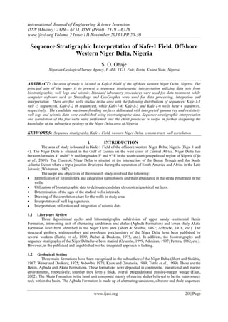
  • 7. Sequence Stratigraphic Interpretation… 4.3.4 Sequence IV (731.52 - 2,273.81 m) This sequence is made up mainly of lowstand systems tract (PGC). The lowstand prograding complex (PGC: 731.52 - 2,273.81 m) is composed of thirteen units of medium to coarse grained sandstones that are interbedded by argillaceous siltstones, siltstones, clays, mudstones, shales, etc. This PGC is non-marine and it is barren of fossils. It constitutes the set of lithofacies that form the Benin Formation. It is of continental fluviatile environment of deposition. There is fault between Kafe-1-2 and Kafe-1-4 wells. The down-thrown side of the recognized growth fault is located at the Kafe-1-4 well area, while the up-thrown side is at the Kafe-1-2 well area (Fig.3). 4.4 Kafe-1-5 Well Four sequences were recognized in this well (Fig. 4). 4.4.1 Sequence I (3,387.24 - 3,535.68 m) Two systems tracts were penetrated in this well; they are the transgressive systems tract and the highstand systems tract. The transgressive systems tract (TST: 3,466.80 - 3,535.68 m) is composed mainly of shales, which fines upward in a retrogradational stacking pattern. The transgressive systems tract is capped by maximum flooding surface (MFS: 12.8 Ma) at depth of 3,466.80 m. The 12.8 Ma MFS is dated with the FDO of Globigerinoides subquadratus (BRÖNNIMANN). The highstand systems tract (HST: 3,387.24 - 3,466.80 m) is composed mainly of sandy mudstone interbedded by thin argillaceous siltstone of about 7.62 m thickness. The highstand systems tract has fining upward stacking pattern. It is truncated at the top by an erosional surface, which defines the sequence boundary (SB: 12.1 Ma) at depth of 3,387.24 m. At the point of inflection, there is an abrupt change in the stacking pattern from net fining upward to a net coarsening upward stacking pattern. 0 500 1,000 Msec 1,500 Growth faults SB 8.5 Ma MFS 9.5 Ma SB 10.35 Ma MFS 10.4 Ma SB 10.6 Ma MFS 11.5 Ma SB 12.1 Ma MFS 12.8 Ma 2,000 2,500 3,000 3,500 Fig. 3. Structures with growth faults along cross-line (strike) 1,600 [Scale: vertical: 100 msec.; horizontal: 10 strike lines] 4.4.2 Sequence II (2,909.93 – 3,387.24 m) This sequence has three systems tracts, namely: lowstand prograding complex, transgressive and highstand systems tracts, respectively. The lowstand prograding complex (PGC: 2,956.56 - 3,387.24 m) is made up of six fine to medium grained sandy units that range in thickness from about 15.24 - 106.68 m. Thin beds of shales and argillaceous siltstones of about 15.24 - 48.77 m thickness separate the sandstone units, respectively. The lower sandstone units are downlap, progradational, while the upper units are toplap with aggradational stacking pattern. These sandy units coarsen upward but at the top, they fine upward into shaly unit, which defines the transgressive surface at depth of 2,956.56 m. The transgressive systems tract (TST: 2,933.10 2,956.56 m) is composed of a set of backstepping parasequences of shales. It begins with the transgressive surface, which is the first and minor marine flooding surface above the lowstand prograding complex. The transgressive systems tract backsteps until the point of maximum marine transgression was reached. It is capped by a major marine flooding surface (MFS: 11.5 Ma) at depth of 2,933.10 m. The 11.5 Ma MFS is dated with the FDO: Globorotalia obesa (BOLLI) and Globorotalia foshi lobata (BERMUDEZ). The highstand systems tract www.ijesi.org 26 | Page
  • 8. Sequence Stratigraphic Interpretation… (HST: 2,909.93 - 2,933.10 m) is composed of shales with fining upward stacking pattern. There is an abrupt change in the gamma ray log signature indicating an erosional truncation that defines the sequence boundary (SB: 10.6 Ma) at depth of 2,909.93 m. 4.4.3 Sequence III (2,417.98 - 2,909.93 m) This sequence has three systems tracts, namely: lowstand prograding complex, transgressive and highstand systems tracts, respectively. The lowstand prograding complex (PGC: 2,575.56 - 2,909.93 m) is made up of four sandy units separated by shaly intercalations. The lower unit is composed of coarse grained sandstones with 83.82 m thickness and overlain by shales with 114.30 m thickness serving as very good reservoir seal. Shales of 7.62 m to 30.48 m thickness interbed the other sandy units, which have thicknesses in range of 30.48 - 91.44 m, respectively. The PGC has net coarsening upward stacking pattern that looks like “inverted Christmas tree” shape in the gamma ray log. There is an abrupt change in the gamma ray log signature signifying transgressive surface at depth of 2,575.56 m. The transgressive systems tract (TST: 2,443.89 - 2,575.56 m) is composed of four units of sands (7.62 - 30.48 m thickness) overlain by shales, which may form good stratigraphic seal over the reservoir sands. Though the overall stacking pattern is retrogradational, the gamma ray log signature indicates that the lower sandy units have individual coarsening upward stacking pattern, while the upper sandy units fine upward into a shaly unit, which defines the major marine flooding surface (MFS: 10.4 Ma) at depth of 2,443.89 m. The 10.4 Ma MFS is dated by the ACME of D. hamatus (MARTINI & BRAMLETTE) and the associated marker fossils are R. pseudoumbilicus (medium 3-5 µm) (GARTNER) and the LDO of Catinaster calyculus (MARTINI & BRAMLETTE). The highstand systems tract (HST: 2,417.98 - 2,443.89 m) is composed of marine shales with fining upward retrogradational stacking pattern. It fines into sandy siltstone at an inflection point marking the sequence boundary (SB: 10.35 Ma) at depth of 2,417.98 m. The 10.35 Ma SB is dated by the LDO of D. hamatus (MARTINI & BRAMLETTE) and the associated marker fossils are Catinaster calyculus (MARTINI & BRAMLETTE), Reticulofenestra haqii (BACKMAN), R. pseudoumbilicus (medium 3-5 µm) (GARTNER). 4.4.4 Sequence IV (1,219.20 - 2,417.98 m) This sequence is principally composed of the lowstand prograding complex (PGC). The PGC is made up of ten sandy units, which are separated to two distinct lithological units on the basis of their environments of deposition. The lower part is made up of two sandy units of 30.48 m thick sandstones interbedded by sandy siltstone at the base and shales at the top. This lower part forms the upper part of the fossiliferous Agbada Formation at depths of 2,273.81 - 2,417.98 m. On the other hand, the upper part is made up of eight sandy units that are medium to coarse grained in texture. These sandy units have 30.48 - 228.60 m thickness and separated by thinly bedded argillaceous siltstones, mudstones, clays and shales. It is non-marine, barren in fossils, and forms the upper part that constitutes the Benin Formation at depths of 1,219.20 - 2,273.81 m. 4.5 Kafe-1-6 Well Four sequences were recognized in Kafe-1-6 well (Fig. 4). 4.5.1 Sequence I (3,845.05 - 3,962.40 m) In this sequence, two systems tracts were penetrated in this well. The systems tracts are the transgressive and highstand systems tracts. The transgressive systems tract (TST: 3,907.23 - 3,962.40 m) is composed of two sandy units of 7.72 - 30.48 m thickness separated by 3.05 - 21.34 m thick shale intercalations. The units have an overall retrogradational stacking pattern. The upper argillaceous sandstone unit fines into a condensed section of shaly unit, which defines the maximum flooding surface (MFS: 12.8 Ma) at depth of 3,907.23 m. The 12.8 Ma MFS is dated with Rectoglandulina comatula (LOEBLICH & TAPPAN) fossil marker. The highstand systems tract (HST: 3,845.05 - 3,907.23 m) is mainly composed of hemi-pelagic shales/mudstones. The overall stacking pattern is aggradational and fines upward with an abrupt change of the gamma ray log signature signifying an erosional truncation that defines the sequence boundary (SB: 12.1 Ma) at depth of 3,845.05 m. The 12.1 Ma sequence boundary is dated with FDO of Calcidiscus premacintyrei (THEODORIDIS) and the associated fossil marker is H. stalis (THEODORIDIS). 4.5.2 Sequence II (3,592.37 - 3,845.05 m) This sequence has two systems tracts, namely: transgressive and highstand systems tracts. The transgressive systems tract (TST: 3,622.55 - 3,845.05 m) is composed of two units of an underlying argillaceous sandstone that is overlain by shales. The gamma ray log signature shows a retrogradational stacking pattern. The www.ijesi.org 27 | Page
  • 9. Sequence Stratigraphic Interpretation… argillaceous sandy unit fines upwardly into shaly condensed section that defines a maximum flooding surface (MFS: 11.5 Ma) at depth of 3,622.55 m. The 11.5 Ma MFS is dated with the FDO of Globorotalia mayeri (CUSHMAN & ELLISOR) and the associated fossil marker is LDO: Globorotalia continuosa (BLOW). The highstand systems tract (HST: 3,592.37 - 3,622.55 m) is composed mainly of shales that fines upwardly and progrades into an erosional truncation that defines a sequence boundary (SB: 10.6 Ma) at depth of 3,592.37 m. The 10.6 Ma sequence boundary is dated with the LDO of D. hamatus (MARTINI & BRAMLETTE) and the FDO of Catinaster coalitus (MARTINI & BRAMLETTE) and the associated fossil markers are D. bellus (BUKRY & PERCIVAL), U. jafari (KAMPTNER) and D. bollii (MARTINI & BRAMLETTE). Sequence III (2,948.33 – 3,592.37 m) Three systems tracts were recognized in this sequence. These are the lowstand prograding complex, transgressive and highstand systems tracts. The lowstand prograding complex (PGC: 3,314.70 - 3,592.37 m) is composed of six sandy units, which are individually interbedded by shales. The overall stacking pattern is aggradational, and coarsens upward. A shaly condensed section that defines the transgressive surface caps the upper sandy unit. The gamma ray log signature also indicates abrupt change from very low value of 20 API to very high value of 125 API, signifying the presence of transgressive surface at depth of 3,314.70 m. The transgressive systems tract (TST: 3,258.01 - 3,314.70 m) is made up of marine shales with retrogradational stacking pattern and fines upwardly to a maximum flooding surface (MFS: 10.4 Ma) at depth of 3,258.01 m. The 10.4 Ma MFS is dated with the ACME of D. hamatus (MARTINI & BRAMLETTE) and the associated marker fossils are R. haqii (BACKMAN), R. pseudoumbilicus (medium 3 - 5µm) (GARTNER) and the FDO of Catinaster calyculus (MARTINI & BRAMLETTE). The shales of the transgressive systems tract may form good seal for the reservoir sands of the underlying PGC. The highstand systems tract (HST: 2,948.33 - 3,258.01 m) is composed of six sandy units. The lower earlier units, at depths of 3,133.34 - 3,238.50 m, have aggradational stacking pattern and coarsen upward. On the other hand, the upper later units have progradational stacking pattern and capped by shaly unit that fines into the erosional truncation, which defines the sequence boundary (SB: 10.35 Ma) at depth of 2,948.33 m. The 10.35 Ma sequence boundary was dated with the LDO of D. hamatus (MARTINI & BRAMLETTE) and the associated marker fossils are Catinaster calyculus (MARTINI & BRAMLETTE), Reticulofenestra haqii (GARTNER) and R. pseudoumbilicus (medium 3-5 µm) (GARTNER). 4.5.3 4.5.4 Sequence IV (1,222.25 - 2,948.33 m) This sequence is made up of lowstand prograding complex. The PGC has two units, namely: marine and non-marine units, respectively. The marine unit, found at depths of 2,301.24 - 2,948.33 m, is made up of sandy units separated by argillaceous siltstones, mudstones, clays and shales that contain fossils. This constitutes the upper part of the Agbada Formation. On the other hand, the non-marine unit is made up of medium to very coarse-grained, thickly bedded sandstones with 15.24 - 152.40 m thickness that are interbedded by thinly bedded argillaceous siltstones, mudstones, clays and shales. This unit (at depth of 1,222.25 - 2,301.24 m) barren of fossils, is of the continental, fluviatile depositional environment and it constitutes the Benin Formation. V. CONCLUSION The aim and objectives of the study were achieved. Several workers have carried out researches into many aspects of the geology, sedimentology, geochemistry, biostratigraphy, seismic stratigraphy and sequence stratigraphy of the Niger Delta area of Nigeria; however, most of the published and unpublished works lack integrated approach to the sequence stratigraphic interpretation. Moreover, the principles and concepts of sequence stratigraphy and the prevailing schools of thought on the subject were discussed. Nevertheless, the discussion on the merit or demerit of the various approaches to sequence stratigraphy was avoided because it is outside the scope of this paper. The interpretation of well log responses (gamma-ray and resistivity logs) was confirmed with ditch cutting characteristics of sediments assessed using stereo-binocular microscopy. The well log patterns were used to delineate the sequences to different kinds of systems tracts. The identified sequence boundaries were found at the inflection of progradation to retrogradation of parasequences in a shallowing upward sand unit, and also at the inflection of the lowstand prograding complexes (lowstand systems tract). The higher gamma ray and lowest resistivity readings were used to identify maximum flooding surfaces, which were further established with biostratigraphic data. There are five wells studied in the area. From the faunal and floral abundance/diversity peaks (using the first and last down-hole occurrences), four maximum flooding surfaces dated 12.8 Ma, 11.5 Ma, 10.4 Ma and 9.5 Ma, and five sequence boundaries dated 13.1 Ma, 12.1 Ma, 10.6 Ma, 10.35 Ma and 8.5 Ma, respectively, were recognized. The fluctuation in specimens abundances have been established to reflect specimens’ migration that has been linked to eustatic changes in sea level. There is a fault between Kafe-1-1 and Kafe-1-2 www.ijesi.org 28 | Page
  • 10. Sequence Stratigraphic Interpretation… wells. The down-thrown side of the recognized growth fault is located at Kafe-1-2 well area, while the upthrown side is at the Kafe-1-1 well area. In addition, there is another growth fault between Kafe-1-2 and Kafe-14 wells. The down-thrown side of this growth fault is located at the Kafe-1-4 well area, while the up-thrown side is at the Kafe-1-2 well area. Erosional truncation and downlap surfaces were prominent structures mapped in the seismic sections for sequence stratigraphic interpretation of the studied wells. The wells were drilled to the depths of 3,782.57 m (Kafe-1-1), 3,791.71 m (Kafe-1-2), 3,489.96 m (Kafe-1-4), 3,535.68 m (Kafe-1-5) and 3,962.40 m (Kafe-1-6). REFERENCES [1]. [2]. [3]. [4]. [5]. [6]. [7]. [8]. [9]. [10]. [11]. [12]. [13]. [14]. [15]. [16]. [17]. [18]. [19]. [20]. [21]. [22]. [23]. [24]. [25]. [26]. [27]. Adegoke, O.S. (2002): High resolution biostratigraphy, sequence stratigraphy, 3-D modeling: indispensable tools for E & P activities in the new millennium. NAPE Bulletin vol. 16, no. 1, pp. 46 – 65. Adeniran, B.V., 1997. Quantitative Neogene planktonic foraminiferal biostratigraphy of western Niger Delta, Nigeria. NAPE Bull. vol. 12, no. 1, pp. 54 – 69. Avbovbo, A.A., 1978. Tertiary lithostratigraphy of Niger Delta, AAPG Geol. Notes, pp. 296 – 300. Berggren, W.A., Kent, D.V. and Avan Couvering, J.A., 1985. The Neogene: Part 2, Neogene geochronology and chronostratigraphy, in Snelling, N.J. (ed.), The Chronology of Geological Record, Geological Society Memoir, vol. 10, pp. 211260. Blow, W.H., 1969. Late Miocene to Recent planktonic foraminifera Biostratigraphy, in Brönnimann, P. and Renz, H.H. (eds.), Proceedings First Int. Conf. on planktonic microfossils, Geneva, 1967, vol. 1, pp. 199-422. Blow, W.H., 1979. The Cainozoic globigerinida. Leiden, E.J. Brill., 3 vol., 1413 pp. Bolli, H.M., Saunders, J.B. and Perch-Nielsen, K., 1987. Planktonic stratigraphy. (Cambridge Earth Sciences Series), Cambridge University Press, 599 p. Borseti, A.M., Cati, F., Colalongo, M.L. & Sartoni, S., 1979. Biostratigraphy & absolute ages of the Italian Neogene. Ann. Geol. Hellen., 7th Internat. Congr. Meditt. Neogene, Athens, pp. 183-197. Doust, H. and Omatsola, E., 1990. Niger Delta, in Edwards, J.D and Santogrossi, P.A. (eds.), Divergent/passive margin basins, American Association of Petroleum Geologists Memoir 48, pp. 201-239. Emery, D. and Myers, K., 1997. Sequence stratigraphy. Blackwell Science, Australia, 297 pp. Esan, A.O., 2002. High resolution sequence stratigraphic and reservoir characterization studies of D -07, D-08 and E-01 sands, Block 2 Meren Field, Offshore, Niger Delta, Publ. M.S. Geology Thesis, Texas A & M University, Texas, USA, 115 pp. Hart, B., 2005. Sequence stratigraphy basics and seismic geometries and patterns of reflector terminations, in Mancini, E.A. (ed.), Sequence stratigraphy for explorationists, Petroleum Technology Transfer Council (PTTC), Eastern Gulf Region, Jackson, Mississippi, 541 p. Iaccarino, S., 1985. Mediterranean Miocene and Pliocene planktonic foraminifera, in Bolli, H.M., Saunders, J.B. and PerchNielsen, K. (eds.), Planktonic Stratigraphy. Cambridge Press, pp. 115-125. Iaccarino, S. and Salvatorini, G., 1982. A framework of planktonic foraminiferal biostratigraphy for Early Miocene to Late Pliocene Mediterranean area. Paleontol. Stratigr. Evol., vol. 2, pp. 115-125. Knox, G.J. and Omatsola, E.M., 1989. Development of the Cenozoic Niger delta in terms of the “escalator regression” model and impact on hydrocarbon distribution, in van der Linden, W.J.M. et al., eds., 1987, Proceedings, KNGMG Symposium on Coastal Lowlands, Geology, Geotechnology: Dordrecht, Kluwer Academic Publishers, pp. 181-202. Martini, E., 1971. Standard Tertiary and Quaternary calcareous nannoplankton zonation, in Farinacci, A. (ed.), Proceedings of the Second Nannoplanktonic Conference, Roma, 1970, Edizioni Technoscienza, Rome, vol. 2, pp. 739-785. Ojo, E.A., Fadiya, L.S. and Ehinola, O.A., 2009. Biozonation and correlation of BDX-1 and BDX-2 wells of deep offshore Niger Delta using calcareous nannofossils. Search and Discovery Article (AAPG) no. 50194, 8 pp. Ozumba, M.B., 1999. High-resolution foraminifera biostratigraphy and sequence stratigraphy of the Middle – Late Miocene of the western Niger Delta, Nigeria. Unpubl. Ph.D. Thesis, Department of Geology, Univ. Port Harcourt, Nigeria, 273 pp. Petters, S.W., 1982. Central West Africa Cretaceous-Tertiary benthic foraminifera and stratigraphy. Palaeontolographica Bd. 179, Abt. A, pp. 1-136. Reijers, T.J.A., 1996. Selected chapters in geology: sedimentary geology and sequence stratigraphy in Nigeria and three case studies and field guide, SPDC, Nigeria, 197 pp. Short, K.C. and Stäuble, A.J., 1967. Outline of geology of Niger Delta. American Association of Petroleum Geologists Bulletin 5, vol. 51, pp. 761-779. Tuttle, L.W.M., Charpentier, R.R. and Brownfield, E.M., 1999. The Niger Delta Petroleum System: Niger Delta Province, Nigeria Cameroon, and Equatorial Guinea, Africa. U.S. Geological Survey Open-File Report 99-50-H, Denver, Colorado, 70 pp. van Wagoner, J.C., Mitchum, R.M., Campion, K.M. and Rahmanian, V.D., 1990. Siliciclastic sequence stratigraphy in well logs, cores and outcrops: concepts of high-resolution correlation of time and facies: Am. Assoc. Petrol. Geol., Methods in Exploration no. 7, pp. 1–55. Vail. P.R., Mitchum, R.M. and Thompson, S. III., 1977. Seismic stratigraphy and global changes of sea level, part 3, relative changes of sea level from coastal onlap, in: Payton, C.W. (ed.), Seismic stratigraphy applications to hydrocarbon exploration: Am. Assoc. Petrol. Geol. Memoir 26, pp. 63–97. Vail. P. R. and Wornardt, W. W., 1990. An integrated approach to exploration and development in the 1990’s: Well log seismic sequence stratigraphy analyses, Trans. of the 41st Annual Convention of the Gulf Coast Assoc. of Geological Societies, Houston, Texas, pp. 630–650. Weber, K. J. and Daukoru, E., 1975. Petroleum geology of the Niger Delta: Proceedings of the 9th World Petroleum Congress, Tokyo, vol. 2, pp. 202-221. Whiteman, A. (1982): Nigeria- its petroleum geology, resources and potential: London, Graham and Trotman, p. 394. www.ijesi.org 29 | Page
  • 11. Sequence Stratigraphic Interpretation… Fig. 4. Sequence stratigraphic and correlation chart of Kafe1 Field wells www.ijesi.org 30 | Page