Download to read offline
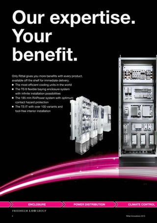
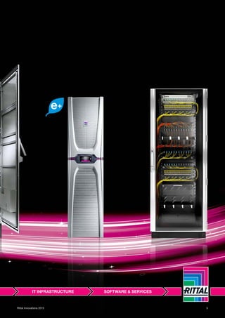
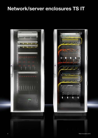
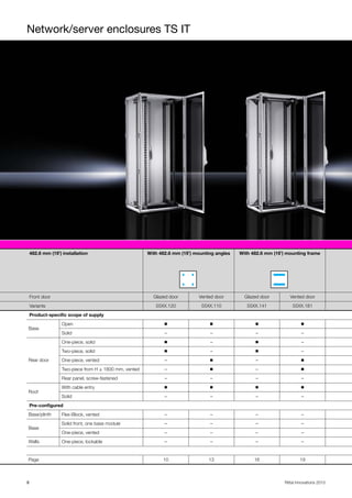
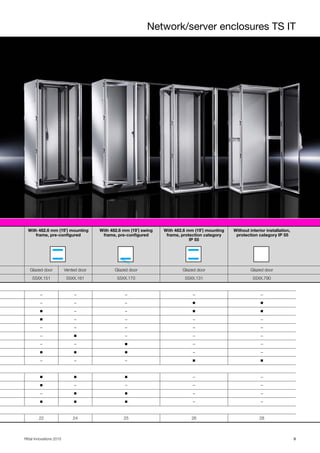
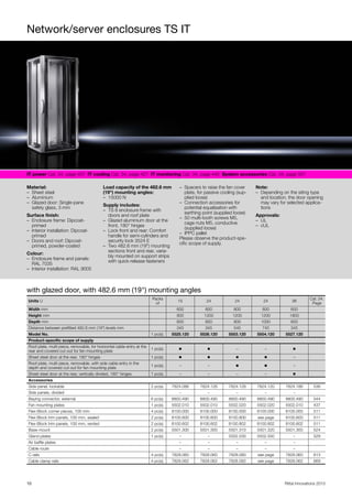

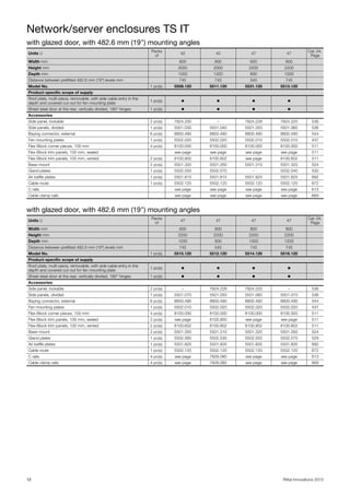


This document provides an overview of Rittal's TS IT network/server enclosures. It describes the key features and benefits of the enclosures, including their modularity, tool-free installation, cable management capabilities, and door concepts. It also lists over 100 pre-configured enclosure variants that are available for fast delivery, along with their specifications and included accessories. The document emphasizes that Rittal offers a complete "Rittal - The System" platform for industrial applications that combines innovative products with efficient service worldwide.


![Servermax Cabinets 61 Data Sheet[1]](https://cdn.slidesharecdn.com/ss_thumbnails/servermaxcabinets61datasheet1-091218161733-phpapp02-thumbnail.jpg?width=640&height=640&fit=bounds)


