Downloaded 26 times


![Enclosure and process cooling 23
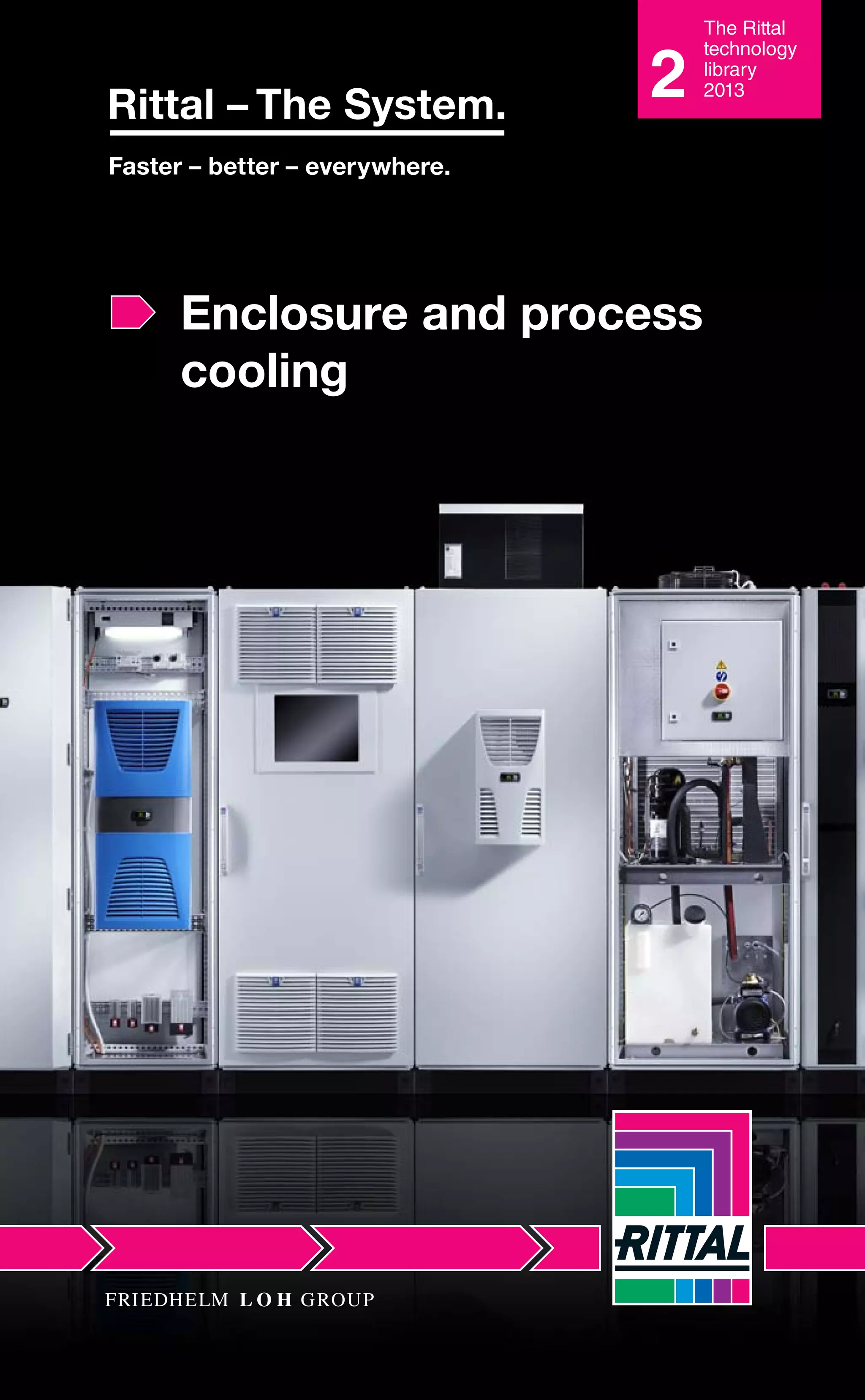
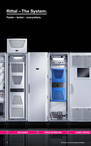
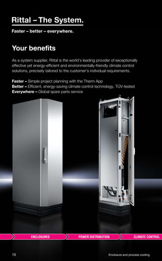
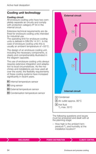
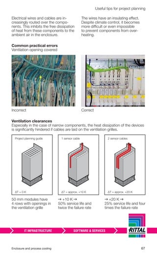
Fundamental principles
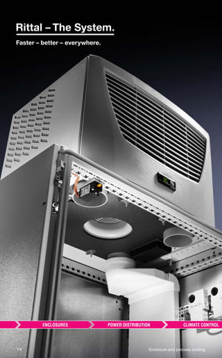
■ Physical calculation principles of heat
dissipation
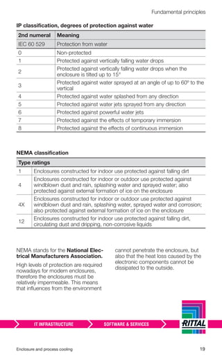
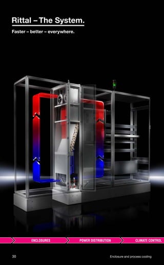
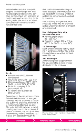
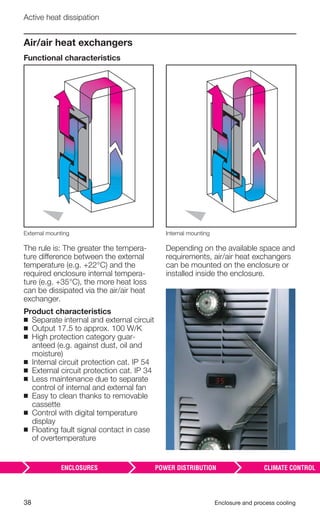
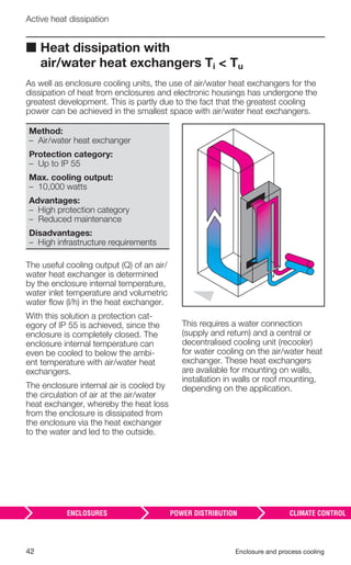
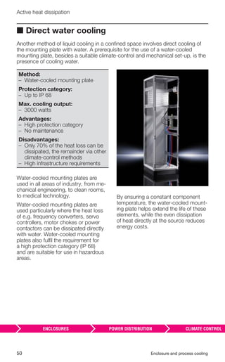
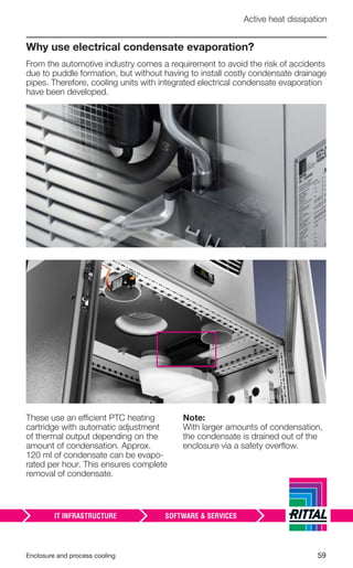
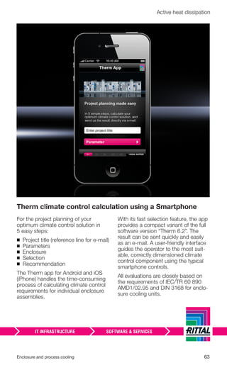
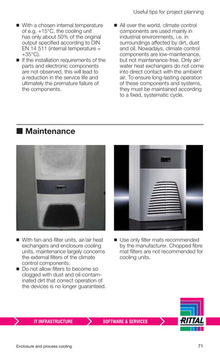
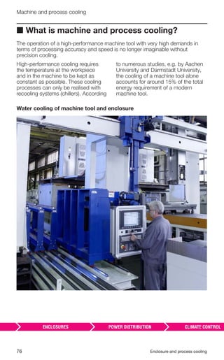
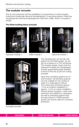
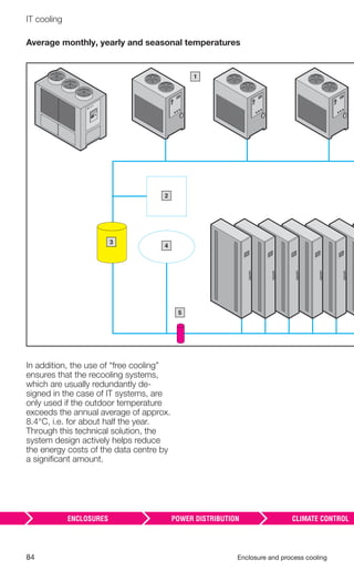
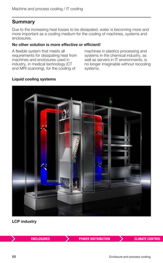
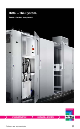
To determine the necessary climate control solution for an enclosure, it is
necessary to calculate the heat loss v in the enclosure. The following
parameters must also be calculated:
Parameter
V Heat loss installed in the enclosure [W]
S Thermal radiation via enclosure surface [W] S = k · A · ΔT
K Required useful cooling output [W]
ΔT
Temperature difference between inside and outside temperature [K]
ΔT = (Ti – Tu)
e
Required cooling output [W]
e = v – s
V
Required volumetric flow of a fan-and-filter unit [m3/h]
Approximate calculation: V =
3.1 · v
ΔT
1
5
2
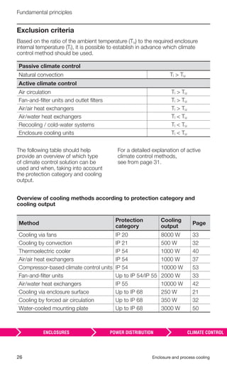
6
Tu
Maximum ambient tem-
perature
Ti
Maximum enclosure
internal temperature
A
Effective enclosure
surface area (VDE)
k Heat transfer coefficient
v Heat loss
s
Thermal radiation via
enclosure surface
IP XX Protection category
Installation method, see
page 24
1
2
3
4
5
6
3 4](https://image.slidesharecdn.com/soredrnmrsevosv7qa2g-signature-999dbf7c4f1a09f9892120e96b01481dfde46ea9d8eed49508eb59fba4be118b-poli-170224162706/85/Enclosure-and-process_cooling-24-320.jpg)
![24 Enclosure and process cooling
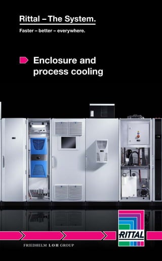
Fundamental principles
The maximum enclosure internal
temperature (Ti) must be determined
depending on the electrical and
electronic components used in the
enclosure.
According to IEC 60 204-1 “Safety of
Machinery”, the electrical equipment
of machines must be able to function
correctly at the envisaged ambient air
temperature. The minimum require-
ment is correct operation at ambient
temperatures of between +5°C and
+40°C. As far as the recommended
enclosure internal temperature is
concerned, an average value of +35°C
has become the norm. This internal
temperature also forms the basis for
all calculations for necessary climate
control solutions in enclosures.
In addition to the physical values de-
scribed above, the enclosure surface
area must also be determined accord-
ing to the installation type.
The corresponding requirements for
each installation type are laid down in
DIN VDE 0660 part 500/IEC 890.
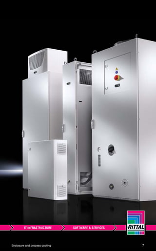
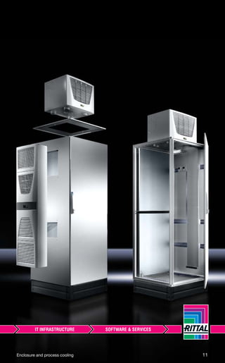
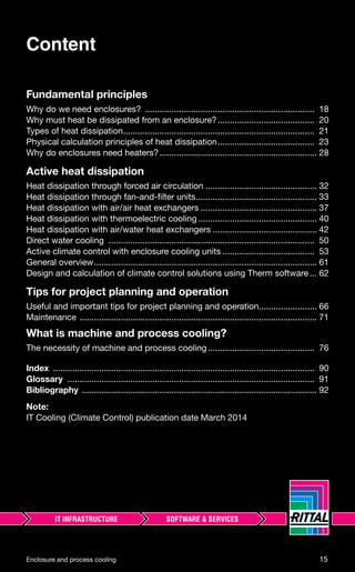
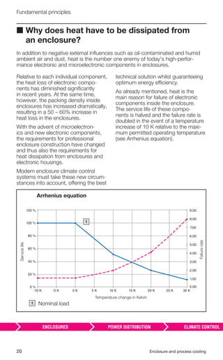
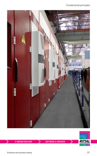
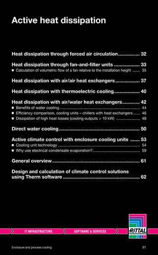
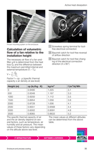
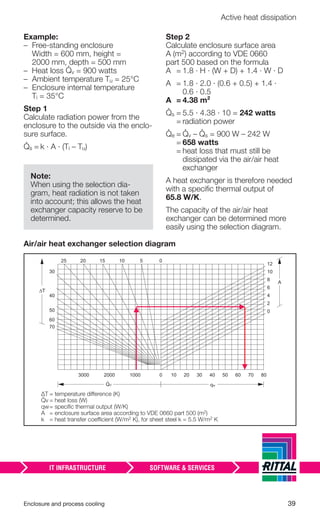
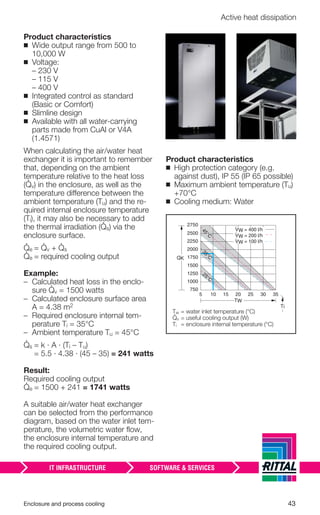
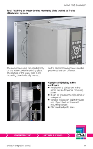
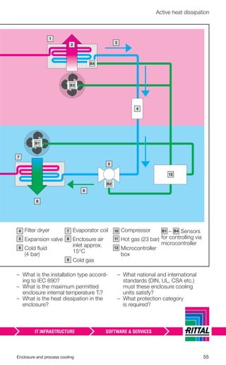
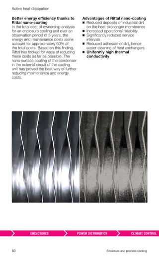
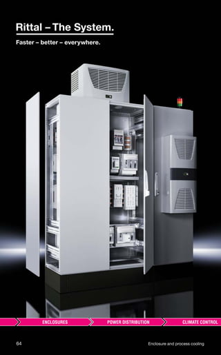
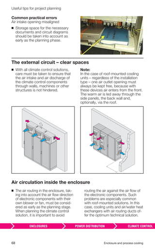
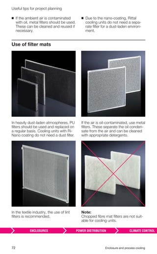
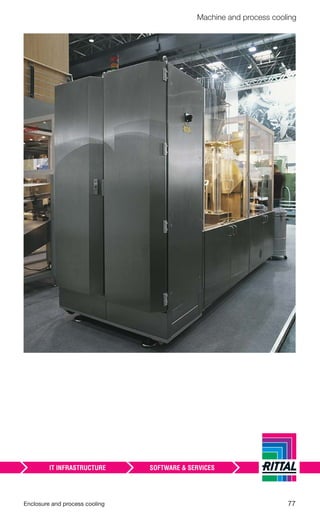
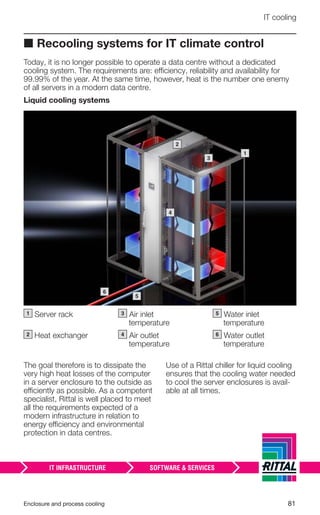
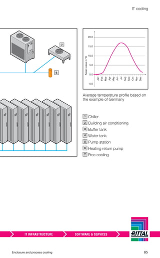
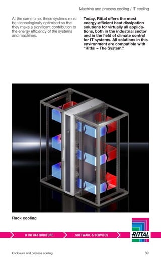
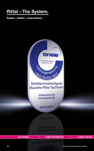
Enclosure installation type according to IEC 60 890
Single enclosure, free-standing on all sides
A = 1.8 · H · (W + D) + 1.4 · W · D
Single enclosure for wall mounting
A = 1.4 · W · (H + D) + 1.8 · H · D
First or last enclosure in a suite, free-standing
A = 1.4 · D · (W + H) + 1.8 · W · H
First or last enclosure in a suite, for wall mounting
A = 1.4 · H · (W + D) + 1.4 · W · D
Enclosure within a suite, free-standing
A = 1.8 · W · H + 1.4 · W · D + H · D
Enclosure within a suite, for wall mounting
A = 1.4 · W · (H + D) + H · D
Enclosure within a suite, for wall mounting, covered roof surfaces
A = 1.4 · W · H + 0.7 · W · D + H · D
A = Effective enclosure surface area [m2]
W = Enclosure width [m]
H = Enclosure height [m]
D = Enclosure depth [m]
The radiating power from the en-
closure to the environment or the
irradiating power from the environment
into the enclosure depends on the
enclosure installation method.
An enclosure that is free-standing on
all sides can dissipate a greater heat
loss to the environment via its surface
(with a positive temperature difference,
Ti > Tu between internal and external
temperature) than an enclosure sited
in a niche or integrated into a machine.](https://image.slidesharecdn.com/soredrnmrsevosv7qa2g-signature-999dbf7c4f1a09f9892120e96b01481dfde46ea9d8eed49508eb59fba4be118b-poli-170224162706/85/Enclosure-and-process_cooling-25-320.jpg)
![Enclosure and process cooling 25
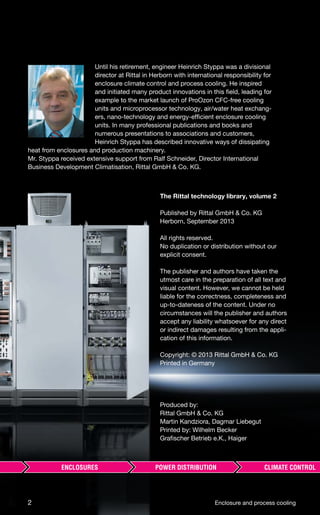
Fundamental principles
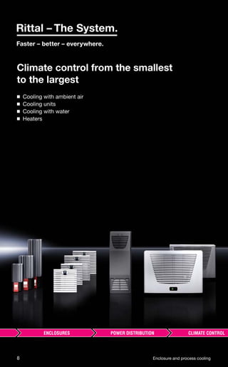
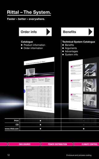
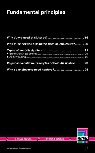
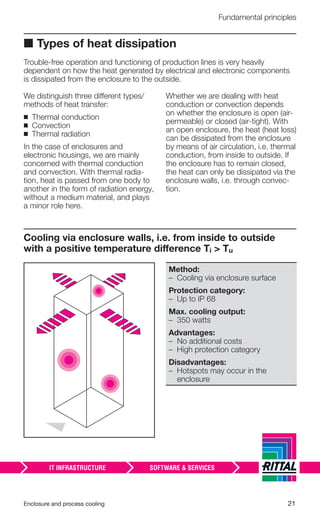
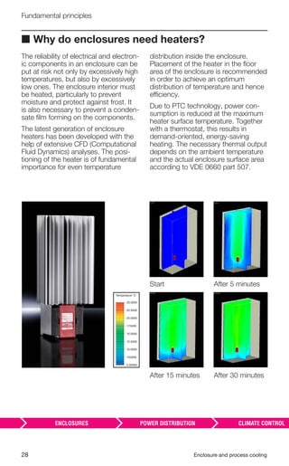
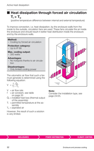
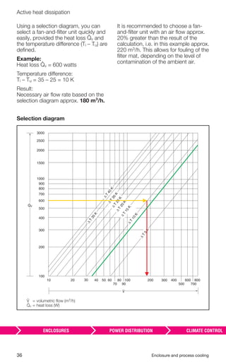
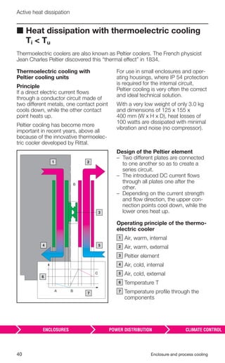
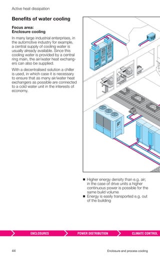
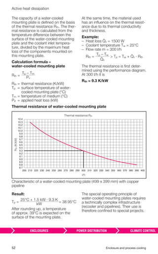
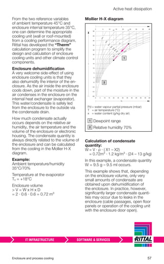
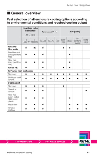
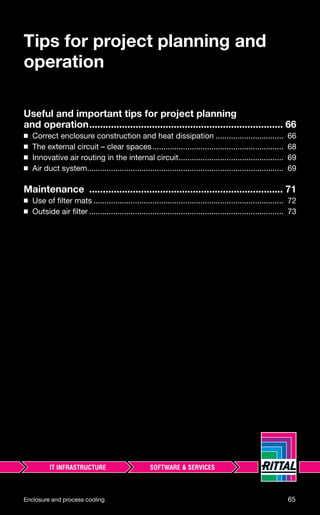
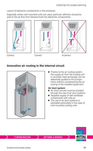
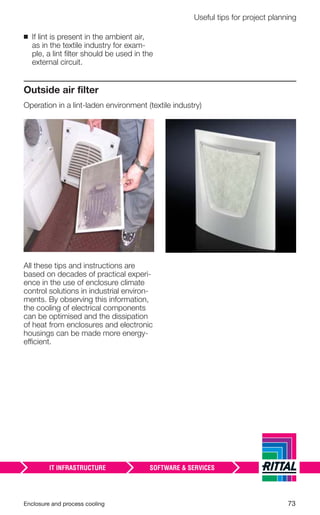
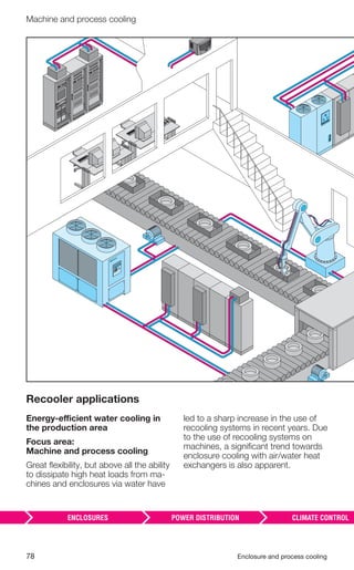
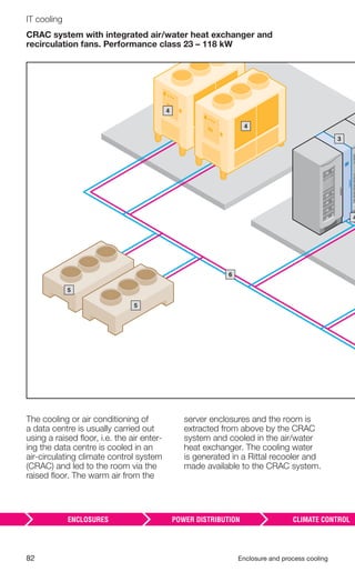
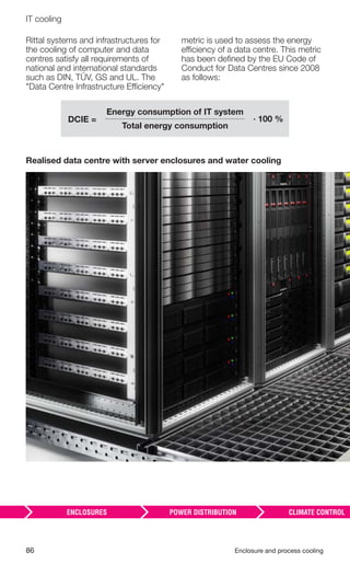
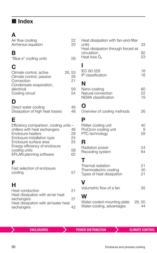
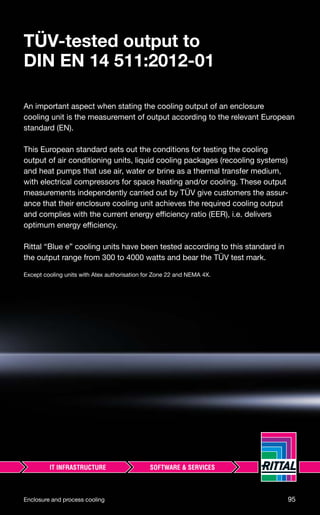
Effective enclosure surface area [m2 ] (VDE 0660 part 507)
The method of installation of the enclosure changes the effective surface area.
Single
enclosure, free-
standing on all
sides
Single enclosure
for wall mount-
ing
First or last
enclosure in
a suite, free-
standing
First or last
enclosure in a
suite, for wall
mounting
Enclosure
within a suite,
free-standing
Enclosure
within a suite,
for wall mount-
ing
Enclosure within
a suite, for wall
mounting, with
covered roof
surfaces](https://image.slidesharecdn.com/soredrnmrsevosv7qa2g-signature-999dbf7c4f1a09f9892120e96b01481dfde46ea9d8eed49508eb59fba4be118b-poli-170224162706/85/Enclosure-and-process_cooling-26-320.jpg)
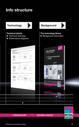
![56 Enclosure and process cooling
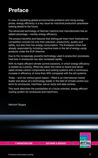
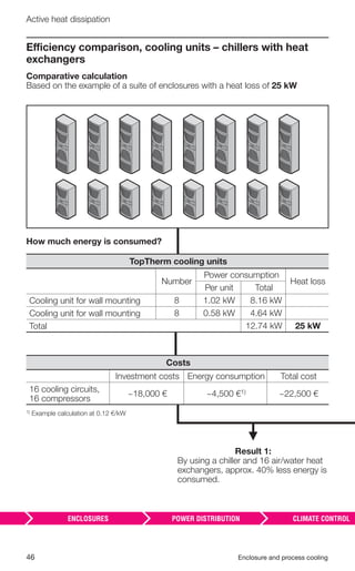
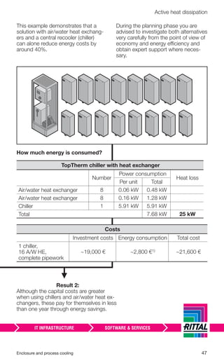
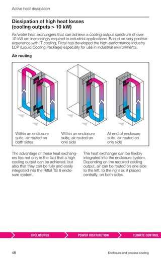
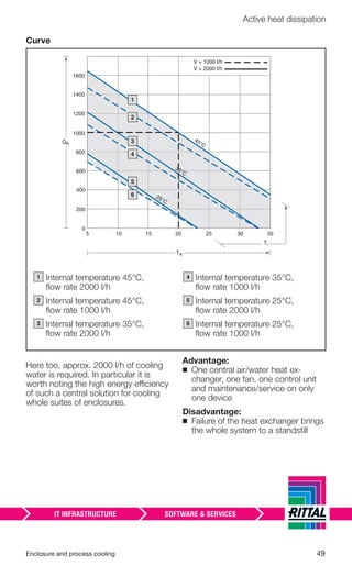
Active heat dissipation
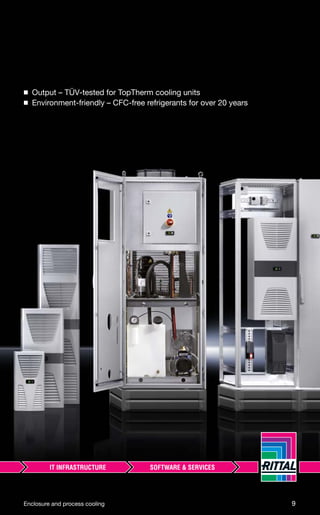
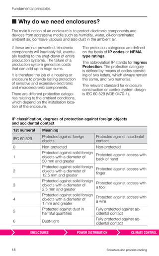
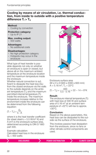
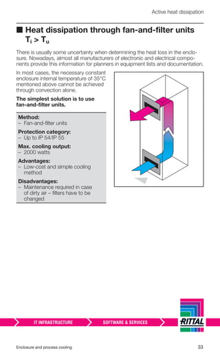
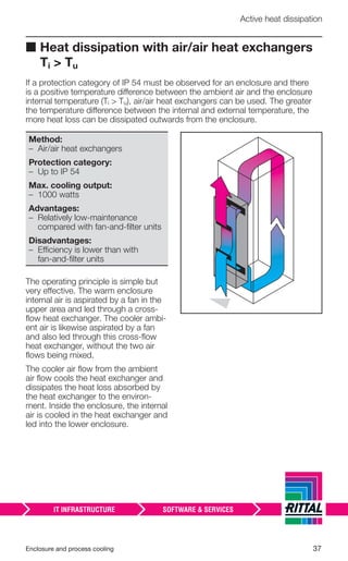
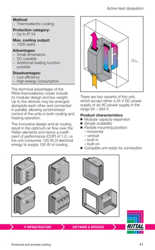
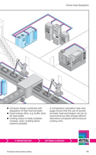
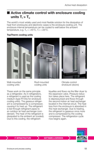
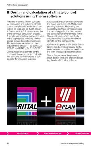
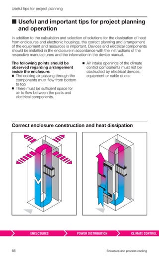
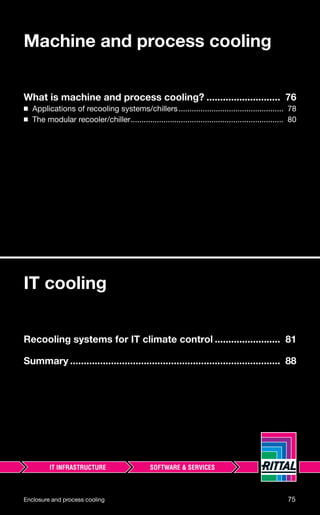
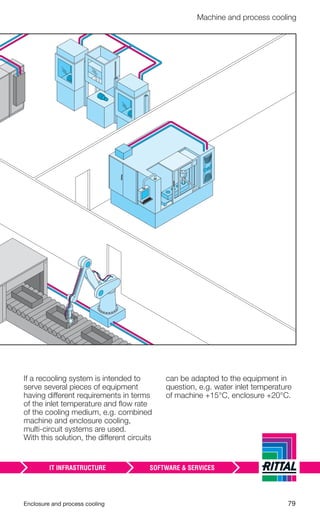
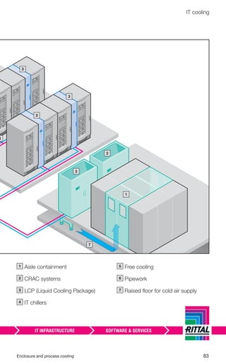
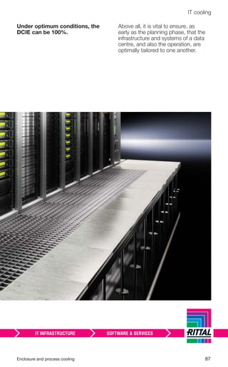
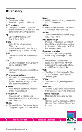
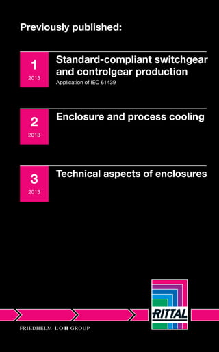
The calculation of an enclosure
cooling unit is described on the
basis of an example.
Heat loss in the enclosure
v = 2000 watts
Enclosure dimensions
(W x H x D) = 600 x 2000 x 500 mm,
free-standing
Ambient temperature
Tu = 45°C
Required internal temperature
Ti = 35°C
Step 1
Calculate enclosure surface area ac-
cording to VDE 0660 part 500:
A = 1.8 · H · (W + D) + 1.4 · W · D
A =
1.8 · 2.0 · (0.6 +0.5) + 1.4 · 0.6 · 0.5
A = 4.38 m²
Step 2
Calculate irradiation from the environ-
ment +45°C to the interior +35°C
(Ti < Tu)
s = k · A · (Ti – Tu)
s = 5.5 · 4.38 · (45 – 35)
s = 242 watts
e = v + s = 2000 + 242
e = 2242 watts
This heat loss must be dissipated to
the outside via the enclosure cooling
unit.
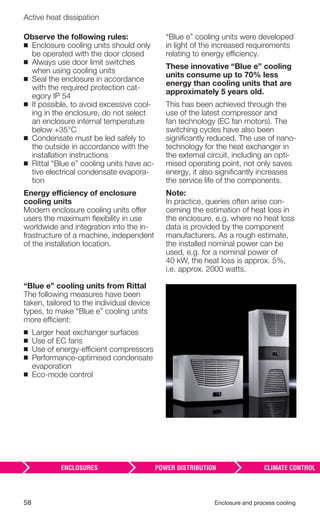
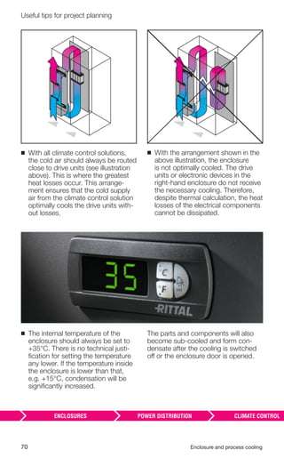
Step 3/Result
For an ambient temperature of +45°C
and an enclosure internal temperature
of +35°C, a cooling unit with a cooling
output of 2242 watts must be found.
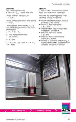
Selection diagram
155 25 35 45 55 65 75
4000
3800
3400
3600
3200
3000
2800
2600
2400
2200
2000
1800
1600
1200
1400
800
1000
4200
4400
65
60
55
50
40
45
30
35
Actualcoolingoutputofcoolingunit[W]
Ambient temperature °C
Internaltemperature[Ti]°C](https://image.slidesharecdn.com/soredrnmrsevosv7qa2g-signature-999dbf7c4f1a09f9892120e96b01481dfde46ea9d8eed49508eb59fba4be118b-poli-170224162706/85/Enclosure-and-process_cooling-57-320.jpg)

![92 Enclosure and process cooling
■ Bibliography
Bliesner, Jürgen: Wichtige Installationshinweise beim Schaltschrankauf-
bau [Important installation instructions for enclosure
design], Siemens AG, 2007.
Rittal GmbH & Co. KG: Praxis-Tipps zur Schaltschrank-Klimatisierung und
Maschinenkühlung [Practical tips for enclosure climate
control and machine cooling], Rittal GmbH & Co. KG,
2004.
Rittal GmbH & Co. KG: Rittal SK – System-Klimatisierung [Rittal SK – System
climate control], Rittal GmbH & Co. KG, 2006.
Siemens AG: Schaltschrankintegration, SINAMICS S120 Booksize/
SIMODRIVE – Systemhandbuch 09/2007
[Enclosure integration, SINAMICS S120 Book-size/
SIMODRIVE – System manual 09/2007], Siemens AG,
2007.
Styppa, Heinrich: Klimatisierung für Gehäuse, Maschinen und Anlagen –
Grundlagen, Komponenten, Anwendungen
[Air-conditioning for enclosures, machines and
plants – Fundamentals, Components, Applications].
Die Bibliothek der Technik, vol. 284,
sv corporate media, 2005.
Schneider, Ralf, et al.: Projektierungshandbuch Schaltschrank-Entwärmung
[Project Planning Manual: Enclosure Heat Dissipation],
2nd edition, December 2011, Süddeutscher Verlag
onpact GmbH, 81677 Munich.](https://image.slidesharecdn.com/soredrnmrsevosv7qa2g-signature-999dbf7c4f1a09f9892120e96b01481dfde46ea9d8eed49508eb59fba4be118b-poli-170224162706/85/Enclosure-and-process_cooling-93-320.jpg)


Here are the key steps to calculate the heat loss in an enclosure: 1. Determine the total heat loss (V) of all installed components in the enclosure: - Add up the heat loss of each individual component as specified in the component datasheets. 2. Calculate the heat dissipation via the enclosure surface (S): - S = k x A x ΔT Where: k = heat transfer coefficient of the enclosure material (typically 5.5 W/m2K for sheet steel) A = surface area of the enclosure ΔT = temperature difference between inside (Ti) and outside (To) of the enclosure 3. Subtract the surface heat dissipation (S)


