Download to read offline


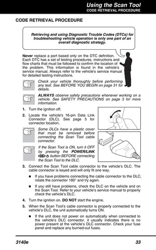


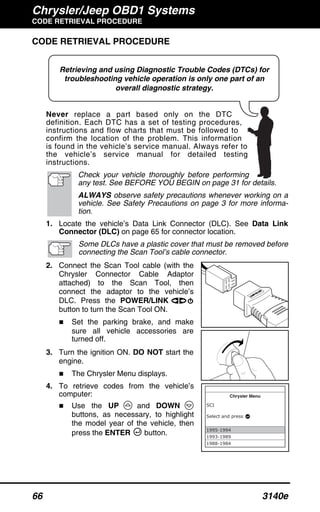


This document provides an overview and instructions for using an automotive scan tool. It describes what onboard diagnostics (OBD) is, which vehicles are OBD2 compliant, the purpose of the scan tool, safety precautions for use, basic scan tool controls and indicators, and sections on connecting to vehicles, retrieving codes, erasing codes, live data, and tests for various vehicle manufacturers. Procedures are provided for GM, Ford, Chrysler, Honda, Toyota and other vehicles, along with a glossary of terms.


![Toyota Dashboard Warning Lights [FULL]](https://cdn.slidesharecdn.com/ss_thumbnails/toyota-warning-lights-211126044903-thumbnail.jpg?width=640&height=640&fit=bounds)
![Mini Cooper Dashboard Warning Lights: Symbols and Meanings [FULL LIST]](https://cdn.slidesharecdn.com/ss_thumbnails/mini-cooper-warning-lights-221021084944-27b65ebd-thumbnail.jpg?width=640&height=640&fit=bounds)


![Mazda Dashboard Warning Lights: Symbols and Meanings [FULL LIST]](https://cdn.slidesharecdn.com/ss_thumbnails/mazda-warning-lights-221021085358-dcf733ba-thumbnail.jpg?width=640&height=640&fit=bounds)


