Inertia dynamics controls_d2650_specsheet
•
1 like•124 views

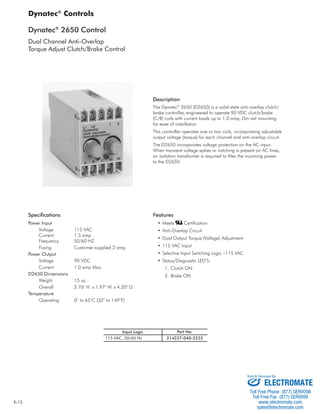
The document describes the Dynatec 2650 dual channel anti-overlap torque adjust clutch/brake control. It provides specifications for the power input and output of the controller. The controller operates one or two 90VDC clutch/brake coils with a maximum current of 1.0 amp. It incorporates adjustable output voltage for each channel and an anti-overlap circuit to prevent excessive wear on clutch/brake systems.

Recommended
More Related Content
What's hot
What's hot (15)
Similar to Inertia dynamics controls_d2650_specsheet
Similar to Inertia dynamics controls_d2650_specsheet (20)
More from Electromate
More from Electromate (20)
Recently uploaded
Recently uploaded (20)
Inertia dynamics controls_d2650_specsheet
- 1. K-12 Dynatec® 2650 Control Dual Channel Anti-Overlap Torque Adjust Clutch/Brake Control Specifi cations Power Input Voltage 115 VAC Current 1.5 amp Frequency 50/60 HZ Fusing Customer-supplied 2 amp Power Output Voltage 90 VDC Current 1.0 amp Max. D2650 Dimensions Weight 15 oz. Overall 2.76" H. x 1.97" W. x 4.30" D. Temperature Operating 0° to 65°C (32° to 149°F) Description The Dynatec® 2650 (D2650) is a solid-state anti-overlap clutch/ brake controller, engineered to operate 90 VDC clutch/brake (C/B) coils with current loads up to 1.0 amp; Din rail mounting for ease of installation. This controller operates one or two coils, incorporating adjustable output voltage (torque) for each channel and anti-overlap circuit. The D2650 incorporates voltage protection on the AC input. When transient voltage spikes or notching is present on AC lines, an isolation transformer is required to fi lter the incoming power to the D2650. Features • Meets Certifi cation • Anti-Overlap Circuit • Dual Output Torque (Voltage) Adjustment • 115 VAC Input • Selective Input Switching Logic –115 VAC • Status/Diagnostic LED’S: 1. Clutch ON 2. Brake ON Dynatec® Controls 115 VAC, 50/60 Hz Part No. 214237-040-2233 Input Logic Sold & Serviced By: ELECTROMATE Toll Free Phone (877) SERVO98 Toll Free Fax (877) SERV099 www.electromate.com sales@electromate.com
- 2. K-13 D2650 Anti-Overlap When using conventional controls where the output voltage is switched by a relay contact, overlap occurs when you see the arching across the contacts. This indicates that just for an instant the brake and clutch are both engaged. This graph represents overlap. The effect of this is excessive wear and heat to the clutch/brake system. The Dynatec® 2650 incorporates MOV’s and time delay logic that will prevent the effects of overlap. This graph illustrates the effects of anti-overlap. Notice the difference between the RPM curves. You have a shorter time to speed and time to zero, and the switching is more precise, creating less heat. These controls can actually operate the clutch/brake system at higher cycle rates, with better repeatability and less heat than conven-tional controls. Dynatec® Controls Brake Off Zero RPM Supply Voltage 90 V DC Clutch/Brake Shaft Rotation Clutch On Time to Speed Overlap Clutch Off Clutch On Brake On Time to Zero Clutch/Brake Shaft RPM Curve using Conventional Control Brake Off Zero RPM No Overlap Run RPM Clutch Off Run RPM Supply Voltage 90 V DC Clutch/Brake Shaft Rotation Clutch On Time to Speed Clutch On Brake On Time to Zero Clutch/Brake Shaft RPM Curve using Dynacorp® Control with Anti-Overlap D2650 Wiring Information L1 L2 1 2 D2650 L2 120 VAC 50/60 Hz L1 Contact 120 VAC Fuse 90 VDC Brake 90 VDC Clutch A B C Rt Rt Rt B Orange Wire Brake White Wire Clutch Orange Wire White Wire Clutch A C Dynacorp® Clutch/Brake Package Wiring 90 V DC Brake 90 V DC Clutch B A C Single Clutch and Brake Wiring Sold & Serviced By: ELECTROMATE Toll Free Phone (877) SERVO98 Toll Free Fax (877) SERV099 www.electromate.com sales@electromate.com