Download to read offline


![Power Dissipation
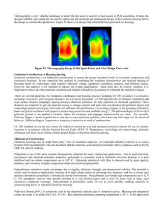
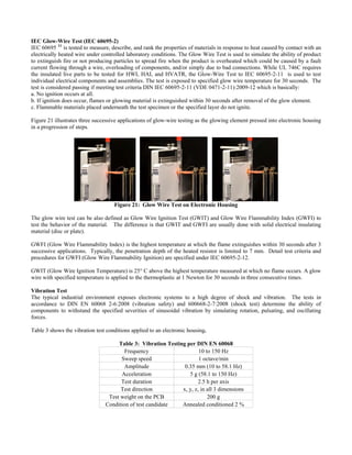
Table 2: Maximum Heat Dissipation:
How Vents and Spacing Change the Maximum Allowed Heating [i]
@ 20°C Ambient Temperature
Vents Present?
Yes No
No spacing between housings 4.4 W 4.3 W
20 mm between housings 8.4 W 7.1 W
[i] Data from Phoenix Contact ME 12,5 series of electronic housings](https://image.slidesharecdn.com/industrialhousingspaperandpresentationcombined-160905224020/85/Industrial-Housings-Paper-and-Presentation-45-320.jpg)
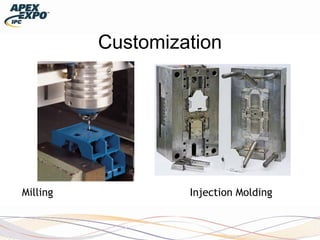
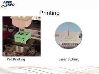
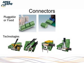


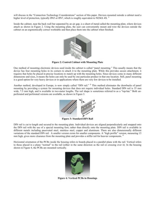
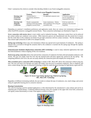
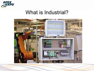
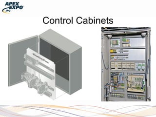
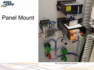
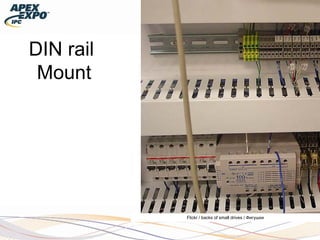
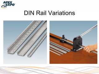
This document discusses the considerations and standards for electronic housings in industrial applications, emphasizing the unique requirements that differ from commercial electronics due to environmental factors like temperature and vibration. It details installation methods such as panel mounting and din rail systems, as well as different types of housings and connection technologies essential for optimal functionality in various industrial settings. Additionally, it explores the importance of customizing housings for safety and aesthetic purposes while meeting specific industry regulations.