SlideShare a Scribd company logo
PROCESS DESIGN A
2014-2015:
Input Gathering Lines and
Storage Tank
Gdansk Oil Terminal
Brendan Smith
bs171@hw.ac.uk
Student ID:H00155203
Abstract
In this design project, Group 12 has been tasked with designingthe new oil terminal in
Gdansk,Poland.The refinery at Gdansk is supplied with oil fromboth the Gdansk port and
the Druzba Oil Pipelinefrom Russia.For this section,the design of the gatheringpipelinewill
considered and the construction of the storage tank with safety considerationswill be
explored in depth.
Artists Depiction of finished Oil Terminal (sourced from Gazoprojekt)
2
Table of Contents
Introduction...............................................................................................................................4
Process Overview ...............................................................................................................5
Overview of Process Employed........................................................................................5
Overall Mass Balance for the Process.............................................................................6
Overall Energy Balance......................................................................................................7
Tank Design.........................................................................................................................7
Type of Tank ....................................................................................................................8
Tank Dimensions.............................................................................................................9
Maintaining Tank Conditions ...................................................................................... 10
Temperature Control.................................................................................................... 11
Materials of Construction ............................................................................................ 13
Further Safety Concerns ............................................................................................. 14
Gathering Pipeline Design .............................................................................................. 16
Introduction.................................................................................................................... 16
Pipeline Parameters..................................................................................................... 16
Suction Side Factors.................................................................................................... 17
Discharge Side Factors............................................................................................... 20
Pump Selection............................................................................................................. 22
Preventing Heat Loss .....................................................................................................0
Heat Exchanger Design .....................................................................................................3
Introduction.......................................................................................................................3
Type of Shell ....................................................................................................................3
Fluid Properties................................................................................................................3
Type of Head....................................................................................................................4
Fluid Allocation ................................................................................................................5
3
Calculation- Tube Side...................................................................................................6
Calculation- Shell Side ...................................................................................................8
Overall Heat Transfer Coefficient (Uo) ...................................................................... 10
Pressure Drop Tube Side ........................................................................................... 10
Pressure Drop Shell Side............................................................................................ 11
Design Justifications .................................................................................................... 11
Report Conclusion............................................................................................................ 12
Equipment Specification Sheets .................................................................................... 12
.......................................................................................... Error! Bookmark not defined.
Introduction
For the oil terminal a number of requirements have been set to achieve in this
project. The design as shown in the cover image, is to have 6 crude oil storage tanks
with each a capacity of 375,000m3. This means around 318,750 tonnes of oil can be
stored per tank (using the average Alvheim field blend density (Norway) which will be
the standard used during this project). This oil is to be either stored to be sent for
refining at the Gdansk refinery or to be further transported by tanker as raw crude oil.
For this project, the process from delivery of crude oil from the Naftoport to the
storage tanks; the vapour recovery and the returning of the oil to either the Naftoport
or sending the oil to the Gdansk refinery will be explored and detailed designs
provided. For the purpose of this technical section, the design of the tank will be
explored, including type of tank, tank parameters, maintaining storage conditions,
materials of construction, and safety concerns associated with the tank design
chosen. The fluid mechanics will be explored in the moving of oil to the storage tank
along the gathering lines associated with the process. This includes type of piping,
piping parameters, pump design, control valve choice and the factors that must be
overcome such as friction and safety concerns. Finally this report will look at a heat
exchanger design that is required to prepare oil for the required storage conditions.
This will involve the type of exchanger, specification of the exchanger and its
justification.
5
Process Overview
The drawing presented below is the area of each individual tank process associated
with this report:
Overview of Process Employed
In the above drawing, the lines L3-1; L4-1; L5-1 are included in the design report with
the design of Pump PU2-1; Tank T1-1; and the Shell and Tube Heat Exchanger
HX4-1 also included. It can be seen that the main line splits into two. With one line
as part of the above process and the other goes to an identical line. Therefore this
design is a standard used for all the 6 oil storage tanks in the facility. The main line
that splits has a flowrate of 5000m3/h and splits into half between each line to the
tanks. Giving a flowrate of 2500m3/h to each tank at peak times.
6
Overall Mass Balance for the Process
A spreadsheet showing the mass balance is shown below. This gives the mass
flowrate and gives the compositions expected for individual components in the oil.
This helps to predict the flash off expected and therefore the load the VRU (vapour
recovery system) can expect. Whilst the mass going in is shown, the expected mass
going out via the VPU is not. This will be detailed in another section in this overall
report.
Mass Balance
VolumetricFlowrate 2500 m^3/h
Overall (Kg/s) 595.00
Component Mass % PerTank InputFeed(Kg/s)
Methane 6 35.7
Ethane 4 23.8
Propane 5 29.75
Butane 9 53.55
Heptane 11 65.45
Hexane 17 101.15
HeavyOil 39 232.05
SaltWater 5 29.75
Nitrogen 1.1 6.545
CO2 1.4 8.33
H2S 1.5 8.925
Total 100 595.00
7
Overall Energy Balance
In this process the overall energy balance is found from the gain in energy from the
heat recovery process and the energy loss as a result of pumping fluid through the
gathering lines. This is outlined below in a spreadsheet:
This shows an overall positive gain of energy because of the energy recovery
system used.
Tank Design
For the design of the tank a number of factors had to be considered. These include:
- Type of Tank
- Tank Dimensions
- Maintaining Tank Conditions
- Materials of Construction
- Safety Considerations
In this order the tank design will be looked at in brief sections.
Energy Balance
Equiptment Energy Consumption/Gain (per unit, J/kg)) Total Energy from Process (J/kg)
Pump -418.2 -836.4
Heat Exchanger 53,400 3,204,000
Total: 3,203,164
where consumption makes for a negative figure
Number of Heat Exchangers 60
Number of Pumps 2
8
Type of Tank
There are two types of tanks used in industry to store liquids:
- Fixed Head Tank
- Floating Roof Tank
Each have their pros and cons and therefore the liquid behaviour and local seasonal
variables must be explored.
Raw Crude Oil in any case will experience flash off of low carbon number
hydrocarbons which form a vapour above the liquid surface. This means the vapour
pressure of these hydrocarbons is much higher and (and associated gases also
entrained in the oil) will begin to form and typically grow the vapour film unless high
pressures/low temperatures are used. Using either of these options would increase
safety concerns and wouldn’t be applicable for oil storage (crude oil is usually stored
at atmospheric pressure). The best way to prevent this using floating roof tanks as
the weight of the roof will stop any vapour forming and sit on top of the liquid. This is
an advantage over the fixed roof tank as pressure relief valves and inert gas supply
would be necessary to prevent pressure build-up which adds more complications to
the design. (Engineering, 2014, pp. 4-5)
Another concern in the design is the seasonal weather conditions of Gdansk.
Gdansk (which is located in the north of Poland on the Baltic coast) is subject to a
temperate climate which means warm summers and very cold winters. This creates
further concern particularly in winter. Winters are subject to seasonal snowfalls which
can result in large build-up of snow depth. This would risk becoming a hazard with
the floating roof tank as the weight could cause the roof to sink below the stored
crude oil allowing for a spill if this snow is not removed. This would require a lot of
man hours to remove and it is very hard to predict when this work would be needed.
Whilst a floating roof is better for dealing with flash off it makes more sense in this
location for fixed roof tanks to be employed. For this reason the fixed roof tank is the
preferred option for the design in this report as it is much easier to control and
predict the behaviour of stored liquid and its vapour output than seasonal weather
forecasting. (Engineering, 2014, p. 5)
9
Tank Dimensions
The aim during the building of tanks is to a) ensure they are safe to use (looking at
the local area and what events happen) and b) to build the most economical tank.
The best way to do this is using mathematical optimisation taking the known
requirement of the volume being 375,000m3. Optimisation can be used to find the
smallest surface area to fulfil the set volume. This has numerous advantages such
as reduced construction cost (less material required); reduces the environmental
effect (less surface area for the wind loading factor); and also reduces the area for
force from the liquid-vapour pressure in the tank to affect. The optimisation method
uses differentiation to find the minimum turning point (at which the least surface
exists at). The following method was employed:
First the equations for both surface area and volume are obtained:
π‘‰π‘œπ‘™π‘’π‘šπ‘’ ( πΆπ‘¦π‘™π‘–π‘›π‘‘π‘’π‘Ÿ) = πœ‹π‘Ÿ2
β„Ž
π‘†π‘’π‘Ÿπ‘“π‘Žπ‘π‘’ π΄π‘Ÿπ‘’π‘Ž ( πΆπ‘¦π‘™π‘–π‘›π‘‘π‘’π‘Ÿ) = 2πœ‹π‘Ÿβ„Ž + 2πœ‹π‘Ÿ2
The volume is equal to 375,000m3 so:
πœ‹π‘Ÿ2
β„Ž = 375,000
So it can be assumed:
β„Ž =
375,000
πœ‹π‘Ÿ2
This can be substituted into the Surface Area equation to remove the height variable
making for a one variable equation. Hence this can be solved to find the radius:
π‘†π‘’π‘Ÿπ‘“π‘Žπ‘π‘’ π΄π‘Ÿπ‘’π‘Ž = 2πœ‹π‘Ÿ (
375,000
πœ‹π‘Ÿ2
)+ 2πœ‹π‘Ÿ2
Simplification finds:
π‘†π‘’π‘Ÿπ‘“π‘Žπ‘π‘’ π΄π‘Ÿπ‘’π‘Ž = (
750,000
π‘Ÿ
) + 2πœ‹π‘Ÿ2
Beginning the differentiation leads to the following:
10
𝑆𝐴′
= 4πœ‹π‘Ÿ βˆ’ (
1,500,000
π‘Ÿ2
)
Making SA’ equal to zero:
4πœ‹π‘Ÿ = (
1,500,000
π‘Ÿ2
)
Multiplying throughout by r2:
4πœ‹π‘Ÿ3
= 1,500,000
Making the radius (at the minimum turning point):
π‘Ÿ = 49.24π‘š
Substituting this back into the volume formula to get height:
β„Ž =
375,000
πœ‹(49.24)2
Getting a height of 49.23m
Surface Area is therefore:
π‘†π‘’π‘Ÿπ‘“π‘Žπ‘π‘’ π΄π‘Ÿπ‘’π‘Ž = 2πœ‹(49.24)(49.23)+ 2πœ‹(49.24)2
Giving a surface area of 30,465.05m2
Maintaining Tank Conditions
It has been proposed that the following conditions are maintained. The tank is to be
kept at atmospheric pressure and 10Β°C. Atmospheric pressure means there is no
pressurised vessel explosion potential, which in turn improves safety. The extra
pressure would require an increased vessel wall thickness which would incur
increased building cost. Keeping the tank at 10Β°C reduces the vapour pressure of
the crude blend, which in turn reduces the amount of flash off of light hydrocarbons
and keeps the oil in mix to be sent to its final destination as a raw material.
11
To maintain pressure and temperature:
- Making use of a pressure relief valve (which sends vapour to a flare or a
Vapour Recovery System (VPU))
- Inert gas supply (here nitrogen will be used)
- Using a temperature control system
TemperatureControl
There are a few designs that could be employed for this requirement which include:
- External Heat Exchange System
- Internal Tank Coils
- Jacketed Vessel
An external heat exchange system would require both piping/pumps and a heat
exchanger such as a shell and tube. There are many options on using this design
which as a result could make it rather complicated. The required pumping power and
pipes would have an extra cost making this non-economical in both the short and
long term. The small temperature difference would make the exchanger inefficient
and with a high flowrate this would make it even more difficult to design (the tank can
contain large amounts of fluid so the required volumetric flowrate to maintain this
temperature would be very high). The other two design options will be considered.
(Richardson, 1999, p. 505)
Internal Coils are another option. For heating, it would be required that the coils be
situated at the bottom (much like a kettle) and for cooling at the top (which is all to do
with heat rising and cold sinking so convection will occur). As both heating and
cooling abilities will be needed, this would increase the area of coils required, with
the overall cost to install and maintain these coils from factors such as corrosion;
increasing the overall cost. However the heat transfer is very good with coils (as
there is direct contact between liquid and heat transfer surface) so it would not be
much trouble to ensure conditions are maintained. There are many options available
for choosing the fluids inside the coil (whether they are heating or cooling) and coils
are widely used in industry so sourcing need not be too much hassle. (Perry, 2008,
p. Section 11 p21)
12
The other option is the Jacketed Vessel design. Jacketed vessels are simply vessels
where within the walls of the vessel are heating/cooling mediums which can reduce
the effect of local temperatures on tank fluid and change temperature in the tank.
This makes the jacketed vessel option very desirable in dealing with the safety
concerns brought about by Gdansk’s local seasons. However jacketed vessels are
not very effective with vessels on the scale that is considered in this design as heat
transfer area would be very limited (to the surface area of the inside of the tank).
(Perry, 2008, p. Section 11 p22)
For this design internal coils have been chosen to perform the maintaining of
temperature in the tank. Below is further design info:
- For large tanks, the hairpin design is typically used as it is easily erected in
the field where it is more economical to construct a storage tank of the scale
considered in this project.
- For heating this is built at the bottom of the tank and for cooling the top due to
heat rising and cold sinking.
- For the size of vessel, it is best to agitate the fluid to improve heat transfer
(note: on the downside, this will encourage more flash off)
- When heating with steam on the coil side, transfer coefficients range between
200 and 400 W/m2 K (Towler, 2009, p. 820)
- When cooling with water, transfer coefficients are between 60-300W/m2 K
(Towler, 2009, p. 819)
- A drawing of the design is shown below:
13
(Perry, 2008, p. Section 11 p21)
Materials of Construction
The choice of building material is important as it must withstand a) pressure of tank
contents and b) local environment variables. For the tank type chosen (fixed roof
tank) there is a chance pressure could build, such as the event of a pressure relief
valve failing. Because the tanks are on the scale they are, it can take hours to empty
the tanks contents so it is important this material can withstand any increased
pressure from within. Otherwise the pressure will be atmospheric so should not
present too many problems but consideration is needed in case of the above event.
Gdansk being close to the coast is subject to storms and high winds. This creates a
factor known as wind loading. From earlier the surface area of the tank is minimised
seriously limiting this effect but this factor is still worth being respectful of. Asides
from this not much else affects Gdansk that would present construction issues.
(Anon., n.d.)
For this design, steel-reinforced concrete will be considered due to its availability,
cost effectiveness and strength. Specifically deformed steel bars will be used. These
are by far the most commonly used and will be post-tensioned. Post-tensioning
means that the concrete will be tensioned on site and this is simply because the tank
is such a large size that it would not be economical to do so in the factory and then
transport such large and numerous pieces to the site. Whilst this requires some
14
special hardware at the end of each steel tendon to anchor them to the concrete, this
is not a big enough issue to consider using pre-tensioned concrete instead. (Perry,
2008, pp. 10-140) (Suchorski, 2000 (Reapproved 2006))
Further SafetyConcerns
Further safety concerns are standard when it comes to designing storage vessels to
contain hydrocarbons:
- Risk of Spills
- Risk of Fire
- Risk of Explosion
- Risk of Corrosion
Risk of spills are a danger to both the installation, the environment and company
reputation. Spills can cost billions in damages as seen with the recent spill in the Gulf
of Mexico by British Petroleum. Whilst the spill by BP is a slightly different scenario it
does demonstrate the affect oil can have if not under close control. In the event of an
oil tank spill the liquid needs to be contained to minimise its affects to the
surrounding area. A good method to do this is designing a bund area or a pool in
which the spilled oil may collect in. It is a simple idea but very effective on the basis it
is designed well and proper response instructions are followed. The Australian
government environmental department suggests the bund area should be able to
contain 133% of the total volume of the vessel requiring bunding (SA, n.d., p. 4). As
vapour is likely in the event of a spill, quick action is required to reduce
environmental impact of escaping gases. This is because methane in a well-known
greenhouse gas which is twenty-times worse than its counterpart carbon dioxide
(US, n.d.). A potential solution could be for the spilled oil to be collected in drains
surrounding to tank and stored underground, this in turn will reduce escaping gases.
The risk of fire is a big problem with crude oil. When burned a thick black smoke
cloud forms which in large quantities can cause health concerns in the local area.
Due to the size of the installation at Gdansk this becomes very important. A similar
accident was seen in London at the Buncefield oil terminal which produces aviation
fuel for neighbouring Gatwick airport (UK, n.d.). The fire caused a cloud of soot
particles to form over London which could be seen from space. Therefore it essential
15
that freighting capabilities are available to the installation. One of the most important
parts of any hydrocarbon combusting is the requirement of oxygen which if cut off,
stops the reactions occurring. In this case a foam injection system can be employed
to help fight crude oil fires. The foam helps cut oxygen off from the oil and being
flame retardant forms an unreactive layer on top of the oil killing and preventing any
flames. (Engineering, 2014, p. 5)
Risk of explosion is another issue requiring consideration. As a fixed roof tank is the
design of choice it comes with an added concern, hydrocarbon vapour formation.
Light hydrocarbons are very susceptible to sudden explosions in the right conditions.
These conditions include being in the vapour phase, in which more surface area in
available for reactions to occur. This results in unstoppable chain reactions. Not only
are these explosions catastrophic to any installation (as fire fighting systems such as
foam injection can be destroyed) but the following fires can add to problems. Whilst
explosions are dangerous, they are easily prevented. Purging the tanks with inert
gases to mix in with hydrocarbons prevents oxygen creating an explosive
atmosphere. Also ignition sources can be eliminated. As hydrocarbons are well-
known insulators, electrical potential can grow inside a tank which with time can
create a spark. By earthing a tank, this potential can be removed. Strict rules are
also needed to prevent workers bringing any potential ignition sources near the tank
area during cleaning for example. (Engineering, 2014, pp. 3-5)
Corrosion is the final risk that should be considered. Since internal heating coils are
being considered for this design it is important to look at what effect the fluid may
have. Since raw crude oil is being stored, this brings the issue of brine and its
corrosive properties. Water is known to corrode metals but this is generally a very
slow process. However alkali metallic salt solutions speed this process up by a large
factor. It has been proposed that water drains are used at the bottom of the vessels.
Water is much denser than oil so sinks and forms at the bottom of tanks when
stationary. This water or brine requires removal to prevent corrosion to the coils
situated at the bottom of the tank. Using drains with level control systems (which can
detect how high water level is due to differing electrical conductivities) can eliminate
this and also create a more desirable crude which has reduced water content
therefore requiring less treating further downstream. (Engineering, 2014, pp. 3-5)
16
Gathering Pipeline Design
Introduction
The naftoport in Gdansk can have up to 4 tankers docked at any one time. From this
it is estimated that a maximum flowrate of 15,000 m3/h can be a possibility in supply
for the storage installation. This is split into three transmission line (each carrying
5,000 m3/h) and each transmission line feeds two tanks (as there are 6 crude
storage tanks) so a flowrate of 2,500 m3/h will be considered in this design.
Furthermore to this the crude oil must be taken to a height of 32.2m so extra head
will be required of the pump. At this stage it’s clear to see a large centrifugal pump
will be required. A balance of both flowrate and head needs to be found so to make
this more economical the line will be further split in two giving two input gathering
lines per tank. This means flowrate in each line will be a maximum of 1250m3/h
reducing the velocity and allowing for a more economical pump to be employed.
As part of the design the following factors will be looked at:
- Pipeline Parameters
- Suction Side Factors (Friction and NPSH)
- Discharge Side Factors (Friction and Head)
- Pump Selection
- Preventing Heat Loss
Pipeline Parameters
A rule of thumb used by engineers estimates the optimum inside diameter of
pipeline. On top of this gathering lines for oil range from 8-12” in diameter. The
equation used for finding the optimum inside diameter is shown:
𝑑𝑖 = 0.33(
𝑀𝐹
𝜌
)
0.5
Where;
- MF is the mass flowrate in kg/s
17
- ρ is the density of the fluid in kg/m3
(Towler, 2009, p. 260)
From this equation the optimum inside diameter was found to be about 195mm.
From this the standard pipe DN300 schedule 20 was chosen (Blue Scope Pipeline
Supplies, 2008). The chosen diameter is larger than the optimum however this was
to keep fluid velocity low enough not to cause significant pressure drops (as the
crude is rather viscous so incurs more friction). This has a wall thickness of 6.4mm.
However it should be considered that crude oil is particularly corrosive so for this
application the inside of the tube will be lined with rubber (with the same thickness as
the tube wall). The outside diameter is 323.9mm. The inside diameter is found by
taking away the wall thickness multiplied by four when the rubber lining is included.
This is demonstrated below:
𝑑𝑖 = 323.9 βˆ’ 4(6.4)
This gives an inside diameter of 298.3mm. From this pipe calculations can be made.
Furthermore to this schedule 20 piping for this pipe gives a pressure rating of 49.95
barg which is more than sufficient as transmission lines are expected to pump fluid at
a maintained ten bar giving a safety factor of just under 5.
It is important to calculate factors such as volumetric flowrate for later calculations on
the suction and discharge sides of the pump. So using the below formula we get:
𝑄 =
𝑀𝐹
𝜌
Where:
- Q is volumetric flowrate
Volumetric flowrate for the whole line will be a maximum of 0.35m3/s.
Suction Side Factors
In terms of the suction side of the pump it must be ensured that pressure drop is not
greater than the pressure supplied by the previous pump or vessel. If so it risks fluid
not making it to the suction point of the pump and the NPSH (Net Positive Suction
Head) being very low or negative. In this design, it is known that pressure in the
18
transmission line was held at 10 bar. However the last pump had to provide pressure
to overcome heat exchangers in the start of the gathering line and pump along a
relatively long pipeline to reach the gathering lines. The following factors are
considered:
- Pressure Drop on first heat exchanger is equal to 0.3 bar
- The length of pipeline from the end of the gathering line start to the pump is
57m
Pressure at the start of the gathering line is 4.625 bar. Once the gathering line
begins, 57m of pipeline must be crossed with a 90 degree junction and gate valve to
also overcome until the suction side of the pump is reached. Following this a
pressure drop of 1.07 bar was calculated allowing for a NPSH of 39.1m at maximum
flowrate. This is sufficient for the pump and eliminates the risk of cavitation.
To calculate pipeline friction losses first fluid velocity; Reynolds number; and relative
roughness must be calculated. They can be found with the following equations:
𝑒 =
𝑄
𝐴
Where:
- u is the velocity
- A is the cross sectional area of the pipe (𝐴 =
πœ‹
4
(𝑑𝑖))
𝑅𝑒 =
πœŒπ‘’π‘‘π‘–
πœ‡
(Towler, 2009, p. 240)
Where:
- ρ is the density of the fluid (850kg/m3)
- Re is the Reynolds number (which is a dimensionless unit)
- ΞΌ is the viscosity of the fluid
𝑅𝑅 =
𝑒
𝑑𝑖
(Towler, 2009, p. 240)
19
Where:
- RR is relative roughness
- e is absolute roughness of pipe material (rubber- 0.00015m)
So velocity is 5m/s; Reynolds number is 143645; and relative roughness is 0.0005.
Also pipe fittings and equipment drops must be accounted for. Along the suction side
there is a heat exchanger (with drop 0.3 bar); a 90Β° bend; a sudden constriction (as
the pipe reduces in diameter from the transmission line diameter); and a gate valve.
For the fittings, the equivalent length method will be used. For this data was used
from Coulson and Richardson’s Volume 6 for the values for pipe fittings (Towler,
2009, p. 243) . The table on the following page shows the fittings equivalent length:
So 55.5 multiplied by the inside diameter will give the equivalent length. This added
to the length of 57m of pipeline that already exists gives a total length of 73.56m.
This can now be applied into the pipe pressure loss equation.
Now the pipe pressure loss can be found:
βˆ†π‘ƒπ‘“ = 8βˆ… (
𝐿
𝑑𝑖
)(
πœŒπ‘’2
2
)
(Towler, 2009, p. 239)
Where:
- βˆ… is the Stanton-Pannell friction factor found from the chart with Reynolds
number and relative roughness (0.0024)
The total pressure drop on this side plus the heat exchanger pressure drop was
found to be 1.07 bar. Now NPSH (Net Positive Head Suction) should be found for
pump specification, found by:
𝑁𝑃𝑆𝐻 = (
𝑃
πœŒπ‘”
) + 𝐻 βˆ’ (
𝑃𝑓
πœŒπ‘”
) βˆ’ (
𝑃𝑣
πœŒπ‘”
)
(Towler, 2009, p. 251)
20
Where:
- P is the pressure at the start of the gathering line
- g is the gravitational acceleration constant (9.81m2/s)
- H is the height of the fluid above the pump centreline (in this case zero)
- Pv is the vapour pressure of the liquid (found to be 29.6kPa)
This gives a NPSH value of 39.1m. This gives plenty of pressure at the suction
nozzle of the pump to prevent cavitation.
DischargeSideFactors
Everything on this side of the pump is working against the energy provided by the
pump. Performing an energy balance finds that without a pump present the fluid
would lack energy by 418 joules for every kilogram of fluid. From this energy balance
it is found that the pump must have a power rating of roughly 165kW (once taking
into account efficiency). To summarise the discharge pipe is a length of 40.2m with a
globe valve; three 900 bends; a set of parallel heat exchangers and pressure drop
from the tank inlet nozzle. This pipe also must climb vertically by 33.2m to reach the
tank inlet. The following page shows the pump data sheet produced for the design:
Like the suction side the pressure drop along the discharge is calculated in the
same way. First the pipe fittings must be accounted for. The table on the following
page shows this:
This gives a total length (equivalent + actual pipeline length) of 250.2m long.
Applying this to the pressure drop formula used in the suction side section and
adding on the pressure drop over the heat exchangers (60kPa), the total comes to
3.22 bar. Now the head required of the pump must be found to define the duty. This
is found by using the equation:
Fitting Equivalent Length
90 degree bend 23d x3
Globe Valve 450d
Tank Inlet 50d
Total 569d
21
π»π‘’π‘Žπ‘‘ π‘…π‘’π‘žπ‘’π‘–π‘Ÿπ‘’π‘‘ = (
𝑃𝑓
πœŒπ‘”
) βˆ’ (
𝑃
πœŒπ‘”
) + 𝑍
(Towler, 2009, p. 245)
Where:
- Z is the height that the fluid must overcome
This gives a head requirement of 40.38m.
Also the energy balance should be found at this point as this can be used later to
find the power rating of the pump. The equation is shown below:
π‘Š = π‘”βˆ†π‘§ +
βˆ†π‘ƒ
𝜌
βˆ’
βˆ†π‘ƒπ‘“
𝜌
Where:
- βˆ†z is the change in height (m)
- g is the gravitational constant (m2/s)
- βˆ†P is the difference in system pressures (N/m2)
- βˆ†Pf is the pressure loss due to friction (N/m2)
(Towler, 2009, p. 245)
This came out at a value of -418J/kg. The negative suggests that a pump is required.
22
Pump Selection
The previous page shows the pump data sheet with the type of pump. This section
aims to justify the choice of pump. The pump chosen is a centrifugal magnetic drive
sealless pump. One of its main applications is in the petrochemical industry so its
design makes it ideal for the fluid being handled. It is capable of handling high
viscosity liquids and can provide the very high flowrate required in this design. More
importantly, it can provide the head needed to lift the crude oil into the tank inlet. The
suction specific speed shows a value greater than 9000 which according to Perry’s
Chemical Engineering Handbook makes this particular pump sitting at the average
for pump design. The sealless design is excellent in preventing spills and leaks
which is important in the transporting of any hydrocarbon. Also the magnetic drive
prevents any heat gain by the liquid as it travels through the pump casing reducing
the requirement of the following heat exchangers. This also in turn increases the
efficiency of the pump as less energy is lost as heat. Being centrifugal makes
maintenance of this pump relatively easy and the manufacturer has designed this
pump to require less maintenance over the course of time. Allowing for more
continuous operation. Its limitations are of course the inability to dry start so fluid is
required to be in the casing prior to start up. There is enough NPSH to allow for this
but in the event of pressure loss upstream this pump must be switched off or risk
breaking down. Finally extra power must be allowed for as if extra head is required
(say if the liquid temperature is lower, making the liquid more viscous) then it should
be available to ensure the process is continuous (M-Pumps, n.d.). More info on this
pump can be found at:
http://www.mpumps.it/?plg_cat_view=c&id=3&g=2
The performance curves of this model of pump defines what size the pump must be.
The following page shows the performance curves:
23
(M-Pumps, n.d.)
0
The performance curve shows the ideal pump is in the 300-500 type. This pump can handle the
flowrate and head plus a little extra if any complications present themselves. Now that the type of
pump is chosen, the power rating can be found. Taking large centrifugal pumps to have an
efficiency between 75-93% (Evans, n.d.)The lowest of this range shall be selected as the viscosity
of the oil is likely to lower the efficiency anyway. The equation to find the power rating is shown:
𝑃𝑅 = π‘Š(𝑀𝐹)/𝑒𝑓𝑓𝑖𝑐𝑖𝑒𝑛𝑐𝑦
(Towler, 2009, p. 245)
Where:
- PR is power rating
The power rating was found to be 165kW.
Preventing Heat Loss
Heat Loss is considered here as winter temperatures in Gdansk can be particularly low. The
temperature of the fluid is important as the lower the fluid is, the more viscous it becomes and
therefore the more resistant to flow it becomes. With oil this is of concern. The piping is already
lined with a thick layer of rubber. Rubber is a well-known insulator so will reduce the heat transfer
to the steel pipe wall. Steel of course is a good conductor so would pass heat easily. A calculation
has been made to show heat loss at average winter night time temperatures and calm conditions
(i.e. low or no wind where only natural convection occurs). Heat Loss can be found from the below
equation:
𝑄 = π‘ˆπ΄π‘œ( π‘‡π‘π‘œ βˆ’ π‘‡π‘Ž)
Where:
- Q is the energy of heat transferred in Watts
- U is the heat transfer coefficient
- Ao is the outside area of the pipe
- Tco is the temperature of the crude oil (30Β°C/303K)
- Ta is the temperature of the surrounding air
(Chopey, n.d.)
1
Average night time temperatures in Gdansk are -2.7Β°C (Ta= 270.3K). The outside area is found
with a simple calculation:
π΄π‘œ = 2πœ‹π‘ŸπΏ
Where:
- r is the radius of the pipe
- L is the length
In the calculation the aim was to find heat loss per meter of pipeline so L in this case was taken as
1. For these calculations the imperial system was used so there was unit conversion at the
beginning and end.
Now U is to be found:
π‘ˆ =
1
π‘Ÿ3
π‘Ÿ1β„Žπ‘–
+
π‘Ÿ3ln(
π‘Ÿ2
π‘Ÿ1
)
π‘˜1
+
π‘Ÿ3ln(
π‘Ÿ3
π‘Ÿ2
)
π‘˜2
+
1
β„Žπ‘œ
Where:
- r3 is the outside radius
- r2 is the radius to the steel wall
- r1 is the radius to the rubber wall (inside radius)
- hi is the inside heat transfer coefficient
- ho is the outside heat transfer coefficient
- k1/k2 are thermal conductivities with respect to their materials
K1 (natural rubber) was found to be 0.13W/m K (Toolbox, n.d.) and K2 (steel) 51W/m K
(Richerson, 2006)
(Chopey, n.d.)
2
A pipe drawing is shown below:
hi was found to be 150W/m k and ho was calculated finding both the heat transfer coefficients due
to convection and radiation. Overall this came to ho being 54
π΅π‘‡π‘ˆ
β„Ž 𝑓 𝑑2 .
This gave a U value of 4.944
π΅π‘‡π‘ˆ
β„Ž 𝑓𝑑2 ℉
After calculating Q and converting it to standard units it gave an answer of 71.36W per m of
pipeline. Since the pipeline prior to the heat exchanger is 60m this loss can become significant.
For this reason the pipeline will require insulation to reduce heat loss to the surroundings. It should
also be noted that this is assuming calm conditions which with a costal location it is unlikely the
loss of heat will be as low as calculated. Types of insulation for outdoor purposes include foam
rubbers, asbestos (not really used however), and polymers.
3
Heat Exchanger Design
Introduction
For the design proposed, it is required that the feed be cooled down to ten degrees centigrade for
storage. However for transportation it is better for the oil to be heated for more laminar flow and
reduced resistance. So a heat exchanger has been designed to bring crude oil temperature from
30Β°C down to storage temperature (10Β°C). For designing the exchanger, a number of factors had
to be considered before getting into calculations:
- The type of shell
- The heat load and fluid properties
- The type of head to use
- Fluid Allocation (to which side fluids are on)
Type of Shell
In this design, the most economical design was chosen, this being the TEMA E-type shell 1:1
pass. This means both shell and tube side have one pass. This design is the most widely used
with heat exchangers in industry. Its downside is the pressure drop is typically larger than some
comparable designs. (Towler, 2009, p. 826)
Fluid Properties
In order to carry out the design calculations, the properties of both fluids should be collected at
both the inlet and outlet temperatures of the fluid respectively. This includes;
- Specific Heat Capacity (J. Burger, 1985)
- Viscosity (Jiskoot, n.d., p. For viscosity)
- Thermal Conductivity (S. K. Elam, 1989)
- Density (Jiskoot, n.d., p. For density)
- Fouling factors (Towler, 2009, p. 822)
The table on the following page shows the properties collected:
4
This also shows the heat load and exit temperature of the cooling water stream (t2). It should be
noted that it was difficult to obtain a lot of the properties of the Alvheim Crude Oil because of the
number of components present. However the change in density and viscosity were possible to
estimate. Using β€œIP Part VII Density, Sediment and Water; Section 2 Continuous Density
Measurement September 1997; Formulae from Annex F "Correlation Equations"; API-ASTM-IP
(ISO 91-1) Petroleum Measurement; TablesdatabasetechnotesspreadsheetDensity Correction”
helped to find the density compensation for temperature for the crude oil. Also using the ASTM
D341 standard to estimate the kinematic viscosity at varying temperatures, helped find the values
of viscosity. These values are fortunately widely available for water. (Laboratory, n.d.)
Type of Head
There are two head types typically used. This is the fixed head and floating head types. For this
design the log mean temperature difference was found to be relatively low, therefore there is not
much risk of thermal stress on the tubes. It is more economical to use the fixed head in this case
as it is much cheaper than the floating head design. (Towler, 2009, p. 826)
Proposed values
T1 (Β°C) 30 t1 (Β°C) 5
T2 (Β°C) 10 t2 (Β°C) 12.22927631
Mass FR (kg/s) 5 6.5
Fluid Properties
Alveheim Crude Oil (Shell Side- T1/T2) Inlet Mean Outlet Cooling Water (Tube Side- t1/t2) Inlet Mean Outlet
Cp (kJ/kg k) 1.9200 4.1009 4.0860 4.0710
(J/kg k) 1920.0000 4085.9500
K (W/m k) 0.1250 0.5795 0.5978 0.6160
p (kg/m^3) 839.3400 846.4850 853.6300 1000.0000 997.9000 995.8000
v (m^2/s) 0.0000 0.0000 0.0000 0.0000 0.0000 0.0000
Β΅ (Ns/m^2) 0.00614 0.00978 0.01343 0.00146 0.00556 0.00965
Ro/Ri (m^2 k/W) 0.0005 0.0010
Heat Load Calculating t2
Q= MCp(T1-T2) Rearranging the heat load equation
Q (kW) 192 t2 12.2292763
W 192000
5
Fluid Allocation
Which side the fluid is allocated to can improve the overall economics of the design. The tube side
fluid is typically:
- The lowest flowrate
- The most corrosive liquid
- The most fouling liquid
Tube side typically is the most difficult at keeping pressure drops low. However tubes are much
more easily cleaned and replaced making the above ideals. Shell side fluid typically has the
following characteristics:
- Highest viscosity
- Highest flowrate
It is better to have the viscous liquid in the shell side as it tends to work better with lower flowrates
and the viscosity also improves the heat transfer of the shell side. As the diameter of the shell is
always greater than tube diameter it is easier to achieve a high flowrate without too much pressure
drop. From the fluid properties it is easy to see the cooling water is much more fouling so passing
this through the tubes is the best option. Also the water should be pumped at a flowrate close to
but not exceeding 4m/s to reduce the fouling. (Towler, 2009, p. 843)
Following this discussion the design can now be calculated and specified following any required
optimisation. For the calculation values of the overall heat transfer coefficient are typically between
60-300W/m2 K however as discovered after numerous trials the coefficient was found to be only
28.5W/m2 K. This may be due to the high fouling of the water and the low flowrates used.
Furthermore the log mean temperature for the optimised design was found to be 10.07Β°C using
the equation shown:
βˆ†π‘‡π‘š =
( 𝑇1 βˆ’ 𝑑2) βˆ’ (𝑇2 βˆ’ 𝑑1)
𝑙𝑛
(𝑇1 βˆ’ 𝑑2)
(𝑇2 βˆ’ 𝑑1)
(Towler, 2009, pp. 838-839)
Where:
- T1 is the entry temperature of Hot Side (Crude Oil)
- T2 is the exit temp. of hot side
- t1 is the entry temp. of the cold side (Cooling Water)
- t2 is the exit temp. of the cold side
6
Applying these values the following formula can be used to find the trial area required:
𝑄 = π‘ˆπ΄βˆ†π‘‡π‘š
Rearranged to:
𝐴 =
𝑄
π‘ˆβˆ†π‘‡π‘š
Giving an area of 1069m2. (Towler, 2009, p. 817)
Calculation- Tube Side
For tube side calculations, the parameters of the tube had to be found. From optimising the
design, it was found that a 10m length (exchangers are more efficient when longer), DN50 tube (2”
outside diameter), which gave a tube area of 1.57m2 (per tube, denoted as At). From this the
number of tubes can be found using:
𝑁𝑑 =
𝐴
𝐴𝑑
Here Nt was found to be 426 tubes.
Now the cross sectional area if the tube inside is found so that fluid velocity and the factors
affecting heat transfer can be found (these factors include Reynolds number and finally Nusselts
number).
𝐴 =
πœ‹
4
di
Where:
- di is the inside diameter (here is 45.8mm)
This gives an area of 0.00165m2. From this the velocity can be found but first the volumetric
flowrate needs to be derived. This is simply the mass flowrate (6.5kg/s) divided by the density
(average density is 846.5kg/m3). This gives a volumetric flowrate of 0.0065m3/s. Velocity is found
with the equation:
𝑉 =
𝑉𝐹
𝐴
7
Where:
- VF is volumetric flowrate
- A is the cross sectional area (found in the previous calculation)
- V is the velocity of the fluid
Here the velocity of the water was found to be 3.95m/s which is close to but not exceeding 4m/s
as required.
Reynolds Number is found now by the equation:
𝑅𝑒 =
π‘‰πœŒπ‘‘π‘–
πœ‡
(Sieder, 1936)
Where μ is the viscosity and ρ is the density.
Re was found to be 32451 which gives turbulent flow.
Prandtl’s number is found from:
π‘ƒπ‘Ÿ =
πœ‡πΆπ‘
𝐾
(Towler, 2009, p. 846)
Where:
- Cp is the specific heat capacity
- K is the thermal conductivity
Here the solution was 38.
Before calculating Nusselt’s number the viscosity correction factor is calculated. This involves first
finding the mean temperature of the tube wall. The solution to this is the average of the two mean
bulk fluid values found by taking the average of the inlet and outlet temperatures of each fluid
respectively. The mean temperature of the wall was found to be 15Β°C. The viscosity correction
factor is given by:
𝑉𝐢 =
πœ‡
πœ‡π‘€
(Towler, 2009, p. 846)
8
Where ΞΌw is the viscosity at the mean tube wall temperature for water.
Nusselt’s number is found from the solution of:
𝑁𝑒 = 0.0023( 𝑅𝑒)0.8(Pr )0.33
(
πœ‡
πœ‡π‘€
)
0.14
(Dittus, 1930)
Here the solution was Nu = 391.5
Now the tube side heat transfer coefficient can be found:
β„Žπ‘– =
𝐾( 𝑁𝑒)
𝑑𝑖
Here, hi was 4954W/m2 K
Calculation- Shell Side
First thing to find is the tube pitch (Pt) and the bundle diameter (Db):
𝑃𝑑 = 1.25π‘‘π‘œ
𝐷𝑏 = π‘‘π‘œ (
𝑁𝑑
0.249
)
0.453
(Kern, 1950)
Here, Pt= 62.5mm and Db= 1.8m
The pitch was chosen with 1.25do spacing as this is the recommended amount for triangular pitch
design. The bundle diameter equation is given by Sinnott as a general correlation he found. To
find the shell diameter the chart given by Coulson and Richardson’s volume 6 gives typical values
for bundle clearances for fixed head exchangers. In this case the value of 26mm was taken.
𝐷𝑠 = 𝐷𝑏 + 0.026
Whilst 1.8m bundle diameter wasn’t on the chart, an assumption was made to 26mm being the
clearance (Towler, 2009, p. 831). This gives a shell diameter of 1.83m. Now the estimated area for
cross flow can be found:
π‘Žπ‘  = 𝐷𝑠𝐡(
π‘ƒπ‘‘βˆ’π‘‘π‘œ
𝑃𝑑
)
9
(Towler, 2009, p. 855)
This gives a value of 0.134m2. Where:
- B is the baffle spacing (which is in this case is equal to Ds/5)
Now equivalent diameter must be found:
(Kern, 1950)
This gives a value of 0.036m. Also the volumetric flowrate is equal to 0.006m3/s. The mean
velocity is therefore:
𝑒 =
𝑉𝐹
π‘Žπ‘ 
Which gives a value of 0.045m/s
The modified Reynolds number must be found. It is modified as the velocity which is normally
used is only an average (as velocity varies throughout the shell cross-sectional area). Now the
value G replaces u where G is the product of volumetric flowrate and density and viscosity it
multiplied by the cross sectional area. This is shown below
𝑅𝑒 =
𝐺𝑑𝑒
π‘Žπ‘ Β΅
(Kern, 1950)
This gives a value of 210. It should be noted that this is laminar flow so the Nusselt’s number is
adjusted for the shell side to account for this. Prandtl’s number is as before giving a value of 150
for oil. Nusselt’s number is found by the equation below (under laminar conditions):
𝑁𝑒 = 1.86( π‘…π‘’π‘ƒπ‘Ÿ)0.33
(
𝑑𝑒
𝐿
)
0.33
(
πœ‡
πœ‡π‘€
)
0.14
(Towler, 2009, p. 847)
10
Where:
- L is the tube length (10m)
This gave Nu=8.83
The outside heat transfer coefficient is found the same way as the inside except it is denoted ho.
The value obtained was 29.66W/m2 K where ΞΌw was 0.01017Ns/m2
The calculated overall heat transfer coefficient can now be found.
Overall Heat Transfer Coefficient (Uo)
Found by the following equation:
1
π‘ˆπ‘œ
=
1
β„Žπ‘–
(
π‘‘π‘œ
𝑑𝑖
) +
𝑋𝑀
𝐾𝑀
(
π‘‘π‘œ
𝐷𝑀
) +
1
β„Žπ‘œ
+ 𝑅𝑖 (
π‘‘π‘œ
𝑑𝑖
) + π‘…π‘œ
(Towler, 2009, p. 817)
Where:
- Xw is the tube wall thickness (3.38mm)
- Kw is the thermal conductivity of steel (51W/m K) (Richerson, 2006)
- dw is the tube wall mean diameter (0.0479m)
Ri/Ro are the fouling factors shown in the fluid properties table. This gave a Uo value of
28.87W/m2K.
It can be seen that the error between trial Uo and calculated Uo is very small and the trial is smaller
than the calculated making this an acceptable value. Now pressure drops must be found for both
sides of the exchanger.
PressureDrop Tube Side
Found by finding the solution to:
βˆ†π‘ƒπ‘“ = 𝑁𝑝(8Π€ [
𝐿
𝑑𝑖
] [
πœ‡
πœ‡π‘€
]
0.14
+ 4)[
πœŒπ‘’2
2
]
(Moody, 1944)
11
Where:
- Np is the number of tube passes (1)
- Π€ is the friction factor found from the Stanton-Pannell friction chart
Π€ is found by finding the relative roughness (which is the absolute roughness divided by the inside
diameter of the tube) against the Re number. Relative roughness is 0.001 (as absolute roughness
of steel is 0.000045m). This gives a Π€ of 0.0025. The pressure drop is therefore 0.55 bar
(550kPa).
PressureDrop ShellSide
This is more important as this determines the drop that has to be compensated for in the pump
design. It is found by using:
βˆ†π‘ƒπ‘“ = 8Π€( 𝑁𝑏 + 1)[
𝐷𝑠
𝑑𝑒
] [
𝑝𝑒2
2
] [
πœ‡
πœ‡π‘€
]
0.14
(Kern, 1950)
Where:
- Nb is the number of baffles (found by L/B) which is 27
As the flow is laminar this time the friction factor is independent of relative roughness. Therefore Π€
is 0.08. The pressure drop calculated is 0.0077 bar (77kPa).
Design Justifications
It was found during the design of this exchanger that it was very difficult to have high flowrates
with acceptable pressure drops and number of tubes. Despite using the largest tubing size
available it simply wasn’t acceptable to flowrates any higher than stated in the specification sheet.
The number of tubes for this design came to 680. Higher flowrates seen tubes in the thousands
and tens of thousands which simply wouldn’t be economical. For this reason it has been decided
that to cool all the fluid down around 60 heat exchangers in parallel would be needed. It is
suggested that perhaps lowering this number and using the coil system in the tank to cool the fluid
may be a better option however the parallel heat exchangers will be considered. On the up side,
the pressure drop achieved shell side for the oil is very good at only 0.01 bar so even a large
number of parallel exchangers would not cause to large a problem. Also the heat recovered by the
water could be used elsewhere on plant to use as hot water or steam at reduced production cost.
12
Report Conclusion
To conclude, this report has covered the relevant topics involved with the process described. A
storage tank has been designed, taking the most economical method via an optimisation
procedure which minimised cost and improved safety. Maintenance of conditions was looked at
including relief valves and immersion coils and the justification for their choice. The type of tank
used and its justification, also its setbacks and how they are handled. Further safety concerns
such as dealing with and preventing disasters like oil spills and fires was explored. The pipeline
design was explored looking at pipe parameters like size, piping losses and lengths. What type of
pump was looked at, giving the specification required of the chosen pump and the justification
given to why it was chosen. A heat exchanger design was detailed showing the most economical
approach and specifying and backing up the choice of exchanger chosen.
Equipment Specification Sheets
(On following pages…)
13
Works Cited
Anon., n.d. climatemps. [Online]
Available at: http://www.gdansk.climatemps.com/
[Accessed 29 March 2015].
Bell, K., 1963. Final Report of the Co-operative Research Program on Shell and Tube Heat
Exchangers.
Blue Scope Pipeline Supplies, 2008. Technical Data Chart. [Online]
Available at:
http://www.bluescopepipelinesupplies.com.au/sites/default/files/Revised_Flip_Chart_BSPS_May_
2008.pdf
[Accessed 14 March 2015].
Chopey, N. P., n.d. Heat Transfer- Heat Loss on uninsulated surfaces. In: Handbook of Chemical
Engineering Calculations (2nd Edition). s.l.:s.n., pp. 7-12 - 7-14.
Dittus, F. a. B. L., 1930. Heat Transfer in automobile radiators of the tubular type. In: University of
California at Berkeley: Publications in Engineering 2, p. 443.
Engineering, D. o. E. I. a. C., 2014. In: Processing Fluids in Process Industries. s.l.:Forth Valley
College, pp. 3-7.
Evans, J., n.d. Pump ED 101. [Online]
Available at: http://www.pumped101.com/efficiency.pdf
[Accessed 21 Feburary 2015].
J. Burger, P. S. M. C., 1985. Thermal Methods of OIl Recovery. [Online]
Available at: https://books.google.co.uk/books?id=9nWgt-
F7TNMC&pg=PA48&lpg=PA48&dq=specific+heat+capacity+of+crude+oil&source=bl&ots=hPcuuB
N4f9&sig=GUJndukm2pKzGIk_kH88h4tSTpw&hl=en&sa=X&ei=_sQbVZmcDcy17gb-
uYHwAw&ved=0CD4Q6AEwCQ#v=onepage&q=specific%20heat%20capacity%2
[Accessed 01 April 2015].
Jiskoot, n.d. Calculate Density. [Online]
Available at: http://www.jiskoot.com/Calculations/Density_VCF/index.html
[Accessed 20 March 2015].
Kern, D., 1950. Process Heat Transfer. s.l.:McGraw-Hill.
14
Laboratory, M. H. T., n.d. Fluid Properties Calculator. [Online]
Available at: http://www.mhtl.uwaterloo.ca/old/onlinetools/airprop/airprop.html
[Accessed 01 April 2015].
Moody, L., 1944. Friction factors for pipe flow, p. 671.
M-Pumps, n.d. CN MAG-M. [Online]
Available at: http://www.mpumps.it/?plg_cat_view=c&id=3&g=2
[Accessed 31 March 2015].
Palen, J. a. T. J., 1969. Solution of shell side flow pressure drop and heat transfer by stream
analysis method, p. 53.
Perry, D. W. G. a. R. H., 2008. Perry's Chemical Engineering Handbook. 8 ed. s.l.:McGraw Hill
Companies.
Richardson, J. M. C. a. J. F., 1999. Chemical Engineering. 6 ed. s.l.:Elsevier.
Richerson, D. W., 2006. Modern Ceramic Engineering- Properties, Processing and Use in Design,
s.l.: CRC Press.
S. K. Elam, I. T. K. S. R. A. A., 1989. Thermal Conductivities of Crude Oils. In: Experimental
Thermal and Fluid Science (Volume 2). s.l.:s.n., pp. 1-6.
SA, E., n.d. EPA South Australia. [Online]
Available at: http://www.epa.sa.gov.au/xstd_files/Waste/Guideline/guide_bunding.pdf
[Accessed 08 Feburary 2015].
Sieder, E. a. T. G., 1936. Heat Transfer and pressure drop of liquids in tubes. In: s.l.:s.n., p. 1429.
Stanton, T. a. P. J., 1914. Similarity of motion in relation to the surface friction of fluids, p. 199.
Suchorski, C. K. N. a. D. M., 2000 (Reapproved 2006). Reinforcement for Concrete- Materials and
Applications, s.l.: American Concrete Institute.
Toolbox, E., n.d. Thermal Conductivities of some common materials and gases. [Online]
Available at: http://www.engineeringtoolbox.com/thermal-conductivity-d_429.html
[Accessed 01 April 2015].
Towler, R. S. a. G., 2009. Chemical Engineering Design. 5 ed. s.l.:Elsevier.
Tubular Heat Exchangers Manufacturers Association, 1988. Standards of the Tubular Heat
Exchanger Manufacturers Association. 7 ed. New York: s.n.
15
UK, H., n.d. Buncefield Incident. [Online]
Available at: http://www.hse.gov.uk/comah/buncefield/buncefield-report.pdf
[Accessed 18 March 2015].
US, E., n.d. EPA US. [Online]
Available at: http://epa.gov/climatechange/ghgemissions/gases/ch4.html
[Accessed 16 Feburary 2015].
0
0

More Related Content

What's hot

Welded steel tanks for storage oil
Welded steel tanks for storage oilWelded steel tanks for storage oil
Welded steel tanks for storage oilYahya Haggag
Β 
floating tank design
floating tank designfloating tank design
floating tank design
Ayman Hasprapo
Β 
Tank Design_training report_mo
Tank Design_training report_moTank Design_training report_mo
Tank Design_training report_moUdayan Biswas
Β 
Tank design - powerpoint slides
Tank design - powerpoint slidesTank design - powerpoint slides
Tank design - powerpoint slides
moamen mohamed
Β 
Storage Tank Farms Layout and Piping
Storage Tank Farms Layout and PipingStorage Tank Farms Layout and Piping
Storage Tank Farms Layout and Piping
Amir Razmi
Β 
Tank design - word
Tank design - wordTank design - word
Tank design - word
moamen mohamed
Β 
143137557 storage-tanks
143137557 storage-tanks143137557 storage-tanks
143137557 storage-tanks
bernard347
Β 
STORAGE - Silo design & construction
STORAGE - Silo design & constructionSTORAGE - Silo design & construction
STORAGE - Silo design & construction
Milling and Grain magazine
Β 
Introduction to Storage Tanks
Introduction to Storage TanksIntroduction to Storage Tanks
Introduction to Storage Tanks
Ankur Sharma
Β 
41914644 storage-tank-design-calculations-seismic-design-overturning-moment-b...
41914644 storage-tank-design-calculations-seismic-design-overturning-moment-b...41914644 storage-tank-design-calculations-seismic-design-overturning-moment-b...
41914644 storage-tank-design-calculations-seismic-design-overturning-moment-b...
141jdf
Β 
Tanktraining
TanktrainingTanktraining
TanktrainingDavid King
Β 
38785106 api-tank-design
38785106 api-tank-design38785106 api-tank-design
38785106 api-tank-design
141jdf
Β 
A comprehensive approach to tank design and tank equipment selection
A comprehensive approach to tank design and tank equipment selectionA comprehensive approach to tank design and tank equipment selection
A comprehensive approach to tank design and tank equipment selection
Mohieddin Hadidi
Β 
Storagetanks2010edition
Storagetanks2010editionStoragetanks2010edition
Storagetanks2010edition
Srini Vasan
Β 
HV tower design 1
HV tower design 1HV tower design 1
HV tower design 1
Thy Khy
Β 
Storage Tank Safety
Storage Tank SafetyStorage Tank Safety
Storage Tank Safety
Bipin ShyamSundar Tiwari
Β 

What's hot (17)

Welded steel tanks for storage oil
Welded steel tanks for storage oilWelded steel tanks for storage oil
Welded steel tanks for storage oil
Β 
floating tank design
floating tank designfloating tank design
floating tank design
Β 
Ppt
PptPpt
Ppt
Β 
Tank Design_training report_mo
Tank Design_training report_moTank Design_training report_mo
Tank Design_training report_mo
Β 
Tank design - powerpoint slides
Tank design - powerpoint slidesTank design - powerpoint slides
Tank design - powerpoint slides
Β 
Storage Tank Farms Layout and Piping
Storage Tank Farms Layout and PipingStorage Tank Farms Layout and Piping
Storage Tank Farms Layout and Piping
Β 
Tank design - word
Tank design - wordTank design - word
Tank design - word
Β 
143137557 storage-tanks
143137557 storage-tanks143137557 storage-tanks
143137557 storage-tanks
Β 
STORAGE - Silo design & construction
STORAGE - Silo design & constructionSTORAGE - Silo design & construction
STORAGE - Silo design & construction
Β 
Introduction to Storage Tanks
Introduction to Storage TanksIntroduction to Storage Tanks
Introduction to Storage Tanks
Β 
41914644 storage-tank-design-calculations-seismic-design-overturning-moment-b...
41914644 storage-tank-design-calculations-seismic-design-overturning-moment-b...41914644 storage-tank-design-calculations-seismic-design-overturning-moment-b...
41914644 storage-tank-design-calculations-seismic-design-overturning-moment-b...
Β 
Tanktraining
TanktrainingTanktraining
Tanktraining
Β 
38785106 api-tank-design
38785106 api-tank-design38785106 api-tank-design
38785106 api-tank-design
Β 
A comprehensive approach to tank design and tank equipment selection
A comprehensive approach to tank design and tank equipment selectionA comprehensive approach to tank design and tank equipment selection
A comprehensive approach to tank design and tank equipment selection
Β 
Storagetanks2010edition
Storagetanks2010editionStoragetanks2010edition
Storagetanks2010edition
Β 
HV tower design 1
HV tower design 1HV tower design 1
HV tower design 1
Β 
Storage Tank Safety
Storage Tank SafetyStorage Tank Safety
Storage Tank Safety
Β 

Viewers also liked

Project Report
Project ReportProject Report
Project ReportBrendan Smith
Β 
Individual report mdp
Individual report mdpIndividual report mdp
Individual report mdpFrederico Costa
Β 
Design engineering report
Design engineering reportDesign engineering report
Design engineering report
imshahbaz
Β 
Report on design engineering
Report on design engineeringReport on design engineering
Report on design engineering
Ravi Patel
Β 
Graded Unit Development Stage
Graded Unit Development StageGraded Unit Development Stage
Graded Unit Development StageBrendan Smith
Β 
Ppt on Report Writing
Ppt on  Report WritingPpt on  Report Writing
Ppt on Report Writing
Shruti Mishra
Β 
Business Aware Project Report
Business Aware Project ReportBusiness Aware Project Report
Business Aware Project ReportBrendan Smith
Β 
Magnetically Levitated (Maglev) Trains (by Israfil Jabrayilov)
Magnetically Levitated (Maglev) Trains (by Israfil Jabrayilov)Magnetically Levitated (Maglev) Trains (by Israfil Jabrayilov)
Magnetically Levitated (Maglev) Trains (by Israfil Jabrayilov)
Israfil Jabrayilov
Β 
INTERNSHIP PROJECT REPORT FINAL Saransh
INTERNSHIP PROJECT REPORT FINAL SaranshINTERNSHIP PROJECT REPORT FINAL Saransh
INTERNSHIP PROJECT REPORT FINAL SaranshSaransh Tewari
Β 
Herold Engineering - Marine Projects (- 2011)
Herold Engineering - Marine Projects (- 2011)Herold Engineering - Marine Projects (- 2011)
Herold Engineering - Marine Projects (- 2011)
CraigDWork
Β 
Effect of tube diameter and surface roughness on fluid flow friction factor d...
Effect of tube diameter and surface roughness on fluid flow friction factor d...Effect of tube diameter and surface roughness on fluid flow friction factor d...
Effect of tube diameter and surface roughness on fluid flow friction factor d...
Mirmanto
Β 
Final Technical Report
Final Technical ReportFinal Technical Report
Final Technical ReportJeremy Evans
Β 
BSM084 - Group 15 - 1413749 - Individual Report - IGas Shale - 2015_01_05 (FI...
BSM084 - Group 15 - 1413749 - Individual Report - IGas Shale - 2015_01_05 (FI...BSM084 - Group 15 - 1413749 - Individual Report - IGas Shale - 2015_01_05 (FI...
BSM084 - Group 15 - 1413749 - Individual Report - IGas Shale - 2015_01_05 (FI...Murat Islam CEng MIMechE
Β 
Experiment 4 friction factor
Experiment 4 friction factorExperiment 4 friction factor
Experiment 4 friction factor
rickyjaycoletagomez
Β 
Equipment diagrams of fluid mechanics lab 1
Equipment diagrams of fluid mechanics lab  1Equipment diagrams of fluid mechanics lab  1
Equipment diagrams of fluid mechanics lab 1
Hafiz Luqman Khalil
Β 
fujairah_oil_terminal
fujairah_oil_terminalfujairah_oil_terminal
fujairah_oil_terminalIrfan ahamed
Β 
Fluids lab manual_2
Fluids lab manual_2Fluids lab manual_2
Fluids lab manual_2
Tanveer Hussain
Β 
Report Writing - Conclusions & Recommendations sections
Report Writing - Conclusions & Recommendations sectionsReport Writing - Conclusions & Recommendations sections
Report Writing - Conclusions & Recommendations sections
Sherrie Lee
Β 

Viewers also liked (18)

Project Report
Project ReportProject Report
Project Report
Β 
Individual report mdp
Individual report mdpIndividual report mdp
Individual report mdp
Β 
Design engineering report
Design engineering reportDesign engineering report
Design engineering report
Β 
Report on design engineering
Report on design engineeringReport on design engineering
Report on design engineering
Β 
Graded Unit Development Stage
Graded Unit Development StageGraded Unit Development Stage
Graded Unit Development Stage
Β 
Ppt on Report Writing
Ppt on  Report WritingPpt on  Report Writing
Ppt on Report Writing
Β 
Business Aware Project Report
Business Aware Project ReportBusiness Aware Project Report
Business Aware Project Report
Β 
Magnetically Levitated (Maglev) Trains (by Israfil Jabrayilov)
Magnetically Levitated (Maglev) Trains (by Israfil Jabrayilov)Magnetically Levitated (Maglev) Trains (by Israfil Jabrayilov)
Magnetically Levitated (Maglev) Trains (by Israfil Jabrayilov)
Β 
INTERNSHIP PROJECT REPORT FINAL Saransh
INTERNSHIP PROJECT REPORT FINAL SaranshINTERNSHIP PROJECT REPORT FINAL Saransh
INTERNSHIP PROJECT REPORT FINAL Saransh
Β 
Herold Engineering - Marine Projects (- 2011)
Herold Engineering - Marine Projects (- 2011)Herold Engineering - Marine Projects (- 2011)
Herold Engineering - Marine Projects (- 2011)
Β 
Effect of tube diameter and surface roughness on fluid flow friction factor d...
Effect of tube diameter and surface roughness on fluid flow friction factor d...Effect of tube diameter and surface roughness on fluid flow friction factor d...
Effect of tube diameter and surface roughness on fluid flow friction factor d...
Β 
Final Technical Report
Final Technical ReportFinal Technical Report
Final Technical Report
Β 
BSM084 - Group 15 - 1413749 - Individual Report - IGas Shale - 2015_01_05 (FI...
BSM084 - Group 15 - 1413749 - Individual Report - IGas Shale - 2015_01_05 (FI...BSM084 - Group 15 - 1413749 - Individual Report - IGas Shale - 2015_01_05 (FI...
BSM084 - Group 15 - 1413749 - Individual Report - IGas Shale - 2015_01_05 (FI...
Β 
Experiment 4 friction factor
Experiment 4 friction factorExperiment 4 friction factor
Experiment 4 friction factor
Β 
Equipment diagrams of fluid mechanics lab 1
Equipment diagrams of fluid mechanics lab  1Equipment diagrams of fluid mechanics lab  1
Equipment diagrams of fluid mechanics lab 1
Β 
fujairah_oil_terminal
fujairah_oil_terminalfujairah_oil_terminal
fujairah_oil_terminal
Β 
Fluids lab manual_2
Fluids lab manual_2Fluids lab manual_2
Fluids lab manual_2
Β 
Report Writing - Conclusions & Recommendations sections
Report Writing - Conclusions & Recommendations sectionsReport Writing - Conclusions & Recommendations sections
Report Writing - Conclusions & Recommendations sections
Β 

Similar to Individual Report (final)

Senior Design Project - B.S. Mechanical Engineering (ITV Research and analysis)
Senior Design Project - B.S. Mechanical Engineering (ITV Research and analysis)Senior Design Project - B.S. Mechanical Engineering (ITV Research and analysis)
Senior Design Project - B.S. Mechanical Engineering (ITV Research and analysis)
Kartik Suvarna
Β 
05 chapt 5 pd section 5.5 process eng final_oct 04
05 chapt 5 pd section 5.5 process eng final_oct 0405 chapt 5 pd section 5.5 process eng final_oct 04
05 chapt 5 pd section 5.5 process eng final_oct 04
kromatographic
Β 
05 chapt 5 pd section 5.5 process eng final_oct 04
05 chapt 5 pd section 5.5 process eng final_oct 0405 chapt 5 pd section 5.5 process eng final_oct 04
05 chapt 5 pd section 5.5 process eng final_oct 04
Ishwarya Srikanth
Β 
Wp5 guidance on fuel oilmonitoring_final
Wp5 guidance on fuel oilmonitoring_finalWp5 guidance on fuel oilmonitoring_final
Wp5 guidance on fuel oilmonitoring_final
Abhijit Ghosh
Β 
SEMINAR REPORT
SEMINAR REPORTSEMINAR REPORT
SEMINAR REPORT
jacksonjohny007
Β 
Cfd modelling of the dry spent fuel storage of a pressurized
Cfd modelling of the dry spent fuel storage of a pressurizedCfd modelling of the dry spent fuel storage of a pressurized
Cfd modelling of the dry spent fuel storage of a pressurized
Alexander Decker
Β 
Optimization of Separator Train in Oil Industry
Optimization of Separator Train in Oil IndustryOptimization of Separator Train in Oil Industry
Optimization of Separator Train in Oil Industry
IRJET Journal
Β 
Graded Unit Project Fuel Purification Final Report Online Submission (1)
Graded Unit Project Fuel Purification Final Report Online Submission (1)Graded Unit Project Fuel Purification Final Report Online Submission (1)
Graded Unit Project Fuel Purification Final Report Online Submission (1)Steven Brady
Β 
Mpc implementation for cdu (2002 nprc gcc)
Mpc implementation for cdu (2002 nprc gcc)Mpc implementation for cdu (2002 nprc gcc)
Mpc implementation for cdu (2002 nprc gcc)Yang Lee
Β 
48 60 b allure of power
48 60 b allure of power48 60 b allure of power
48 60 b allure of powerpasanac77
Β 
Design and implementation of a control structure for quality products in a cr...
Design and implementation of a control structure for quality products in a cr...Design and implementation of a control structure for quality products in a cr...
Design and implementation of a control structure for quality products in a cr...
ISA Interchange
Β 
5 heat exchanger thermal design of oil system for turbo centrifugal compresso...
5 heat exchanger thermal design of oil system for turbo centrifugal compresso...5 heat exchanger thermal design of oil system for turbo centrifugal compresso...
5 heat exchanger thermal design of oil system for turbo centrifugal compresso...
IJCMESJOURNAL
Β 
Assignment 1 Technical and economic review of four possible methods of develo...
Assignment 1 Technical and economic review of four possible methods of develo...Assignment 1 Technical and economic review of four possible methods of develo...
Assignment 1 Technical and economic review of four possible methods of develo...Nikolaos Felessakis
Β 
SMID_016_AeroderivativeGTsforLNGPlants
SMID_016_AeroderivativeGTsforLNGPlantsSMID_016_AeroderivativeGTsforLNGPlants
SMID_016_AeroderivativeGTsforLNGPlantsDexter Vaz
Β 
Portable Fuel Tank - The Application of a New Method of Bunkering for Small S...
Portable Fuel Tank - The Application of a New Method of Bunkering for Small S...Portable Fuel Tank - The Application of a New Method of Bunkering for Small S...
Portable Fuel Tank - The Application of a New Method of Bunkering for Small S...Kelvin Xu (MRINA)
Β 
Chapter 3.1_Immiscible Gas Injection1.pdf
Chapter 3.1_Immiscible Gas Injection1.pdfChapter 3.1_Immiscible Gas Injection1.pdf
Chapter 3.1_Immiscible Gas Injection1.pdf
TsaniSabila
Β 
Internship Report
Internship ReportInternship Report
Internship ReportAmmara Haider
Β 
College refinery panipatppt final (1).pptx
College refinery panipatppt final (1).pptxCollege refinery panipatppt final (1).pptx
College refinery panipatppt final (1).pptx
Adisanu
Β 
Waste heat recovery system on board ships
Waste heat recovery system on board shipsWaste heat recovery system on board ships
Waste heat recovery system on board ships
fahrenheit
Β 

Similar to Individual Report (final) (20)

Senior Design Project - B.S. Mechanical Engineering (ITV Research and analysis)
Senior Design Project - B.S. Mechanical Engineering (ITV Research and analysis)Senior Design Project - B.S. Mechanical Engineering (ITV Research and analysis)
Senior Design Project - B.S. Mechanical Engineering (ITV Research and analysis)
Β 
05 chapt 5 pd section 5.5 process eng final_oct 04
05 chapt 5 pd section 5.5 process eng final_oct 0405 chapt 5 pd section 5.5 process eng final_oct 04
05 chapt 5 pd section 5.5 process eng final_oct 04
Β 
05 chapt 5 pd section 5.5 process eng final_oct 04
05 chapt 5 pd section 5.5 process eng final_oct 0405 chapt 5 pd section 5.5 process eng final_oct 04
05 chapt 5 pd section 5.5 process eng final_oct 04
Β 
Wp5 guidance on fuel oilmonitoring_final
Wp5 guidance on fuel oilmonitoring_finalWp5 guidance on fuel oilmonitoring_final
Wp5 guidance on fuel oilmonitoring_final
Β 
SEMINAR REPORT
SEMINAR REPORTSEMINAR REPORT
SEMINAR REPORT
Β 
Cfd modelling of the dry spent fuel storage of a pressurized
Cfd modelling of the dry spent fuel storage of a pressurizedCfd modelling of the dry spent fuel storage of a pressurized
Cfd modelling of the dry spent fuel storage of a pressurized
Β 
Optimization of Separator Train in Oil Industry
Optimization of Separator Train in Oil IndustryOptimization of Separator Train in Oil Industry
Optimization of Separator Train in Oil Industry
Β 
Graded Unit Project Fuel Purification Final Report Online Submission (1)
Graded Unit Project Fuel Purification Final Report Online Submission (1)Graded Unit Project Fuel Purification Final Report Online Submission (1)
Graded Unit Project Fuel Purification Final Report Online Submission (1)
Β 
Mpc implementation for cdu (2002 nprc gcc)
Mpc implementation for cdu (2002 nprc gcc)Mpc implementation for cdu (2002 nprc gcc)
Mpc implementation for cdu (2002 nprc gcc)
Β 
48 60 b allure of power
48 60 b allure of power48 60 b allure of power
48 60 b allure of power
Β 
Design and implementation of a control structure for quality products in a cr...
Design and implementation of a control structure for quality products in a cr...Design and implementation of a control structure for quality products in a cr...
Design and implementation of a control structure for quality products in a cr...
Β 
5 heat exchanger thermal design of oil system for turbo centrifugal compresso...
5 heat exchanger thermal design of oil system for turbo centrifugal compresso...5 heat exchanger thermal design of oil system for turbo centrifugal compresso...
5 heat exchanger thermal design of oil system for turbo centrifugal compresso...
Β 
Assignment 1 Technical and economic review of four possible methods of develo...
Assignment 1 Technical and economic review of four possible methods of develo...Assignment 1 Technical and economic review of four possible methods of develo...
Assignment 1 Technical and economic review of four possible methods of develo...
Β 
SMID_016_AeroderivativeGTsforLNGPlants
SMID_016_AeroderivativeGTsforLNGPlantsSMID_016_AeroderivativeGTsforLNGPlants
SMID_016_AeroderivativeGTsforLNGPlants
Β 
Portable Fuel Tank - The Application of a New Method of Bunkering for Small S...
Portable Fuel Tank - The Application of a New Method of Bunkering for Small S...Portable Fuel Tank - The Application of a New Method of Bunkering for Small S...
Portable Fuel Tank - The Application of a New Method of Bunkering for Small S...
Β 
Chapter 3.1_Immiscible Gas Injection1.pdf
Chapter 3.1_Immiscible Gas Injection1.pdfChapter 3.1_Immiscible Gas Injection1.pdf
Chapter 3.1_Immiscible Gas Injection1.pdf
Β 
HEP_Feb2013_VRT
HEP_Feb2013_VRTHEP_Feb2013_VRT
HEP_Feb2013_VRT
Β 
Internship Report
Internship ReportInternship Report
Internship Report
Β 
College refinery panipatppt final (1).pptx
College refinery panipatppt final (1).pptxCollege refinery panipatppt final (1).pptx
College refinery panipatppt final (1).pptx
Β 
Waste heat recovery system on board ships
Waste heat recovery system on board shipsWaste heat recovery system on board ships
Waste heat recovery system on board ships
Β 

Individual Report (final)

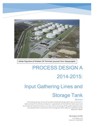
  • 1. PROCESS DESIGN A 2014-2015: Input Gathering Lines and Storage Tank Gdansk Oil Terminal Brendan Smith bs171@hw.ac.uk Student ID:H00155203 Abstract In this design project, Group 12 has been tasked with designingthe new oil terminal in Gdansk,Poland.The refinery at Gdansk is supplied with oil fromboth the Gdansk port and the Druzba Oil Pipelinefrom Russia.For this section,the design of the gatheringpipelinewill considered and the construction of the storage tank with safety considerationswill be explored in depth. Artists Depiction of finished Oil Terminal (sourced from Gazoprojekt)
  • 2. 2 Table of Contents Introduction...............................................................................................................................4 Process Overview ...............................................................................................................5 Overview of Process Employed........................................................................................5 Overall Mass Balance for the Process.............................................................................6 Overall Energy Balance......................................................................................................7 Tank Design.........................................................................................................................7 Type of Tank ....................................................................................................................8 Tank Dimensions.............................................................................................................9 Maintaining Tank Conditions ...................................................................................... 10 Temperature Control.................................................................................................... 11 Materials of Construction ............................................................................................ 13 Further Safety Concerns ............................................................................................. 14 Gathering Pipeline Design .............................................................................................. 16 Introduction.................................................................................................................... 16 Pipeline Parameters..................................................................................................... 16 Suction Side Factors.................................................................................................... 17 Discharge Side Factors............................................................................................... 20 Pump Selection............................................................................................................. 22 Preventing Heat Loss .....................................................................................................0 Heat Exchanger Design .....................................................................................................3 Introduction.......................................................................................................................3 Type of Shell ....................................................................................................................3 Fluid Properties................................................................................................................3 Type of Head....................................................................................................................4 Fluid Allocation ................................................................................................................5
  • 3. 3 Calculation- Tube Side...................................................................................................6 Calculation- Shell Side ...................................................................................................8 Overall Heat Transfer Coefficient (Uo) ...................................................................... 10 Pressure Drop Tube Side ........................................................................................... 10 Pressure Drop Shell Side............................................................................................ 11 Design Justifications .................................................................................................... 11 Report Conclusion............................................................................................................ 12 Equipment Specification Sheets .................................................................................... 12 .......................................................................................... Error! Bookmark not defined.
  • 4. Introduction For the oil terminal a number of requirements have been set to achieve in this project. The design as shown in the cover image, is to have 6 crude oil storage tanks with each a capacity of 375,000m3. This means around 318,750 tonnes of oil can be stored per tank (using the average Alvheim field blend density (Norway) which will be the standard used during this project). This oil is to be either stored to be sent for refining at the Gdansk refinery or to be further transported by tanker as raw crude oil. For this project, the process from delivery of crude oil from the Naftoport to the storage tanks; the vapour recovery and the returning of the oil to either the Naftoport or sending the oil to the Gdansk refinery will be explored and detailed designs provided. For the purpose of this technical section, the design of the tank will be explored, including type of tank, tank parameters, maintaining storage conditions, materials of construction, and safety concerns associated with the tank design chosen. The fluid mechanics will be explored in the moving of oil to the storage tank along the gathering lines associated with the process. This includes type of piping, piping parameters, pump design, control valve choice and the factors that must be overcome such as friction and safety concerns. Finally this report will look at a heat exchanger design that is required to prepare oil for the required storage conditions. This will involve the type of exchanger, specification of the exchanger and its justification.
  • 5. 5 Process Overview The drawing presented below is the area of each individual tank process associated with this report: Overview of Process Employed In the above drawing, the lines L3-1; L4-1; L5-1 are included in the design report with the design of Pump PU2-1; Tank T1-1; and the Shell and Tube Heat Exchanger HX4-1 also included. It can be seen that the main line splits into two. With one line as part of the above process and the other goes to an identical line. Therefore this design is a standard used for all the 6 oil storage tanks in the facility. The main line that splits has a flowrate of 5000m3/h and splits into half between each line to the tanks. Giving a flowrate of 2500m3/h to each tank at peak times.
  • 6. 6 Overall Mass Balance for the Process A spreadsheet showing the mass balance is shown below. This gives the mass flowrate and gives the compositions expected for individual components in the oil. This helps to predict the flash off expected and therefore the load the VRU (vapour recovery system) can expect. Whilst the mass going in is shown, the expected mass going out via the VPU is not. This will be detailed in another section in this overall report. Mass Balance VolumetricFlowrate 2500 m^3/h Overall (Kg/s) 595.00 Component Mass % PerTank InputFeed(Kg/s) Methane 6 35.7 Ethane 4 23.8 Propane 5 29.75 Butane 9 53.55 Heptane 11 65.45 Hexane 17 101.15 HeavyOil 39 232.05 SaltWater 5 29.75 Nitrogen 1.1 6.545 CO2 1.4 8.33 H2S 1.5 8.925 Total 100 595.00
  • 7. 7 Overall Energy Balance In this process the overall energy balance is found from the gain in energy from the heat recovery process and the energy loss as a result of pumping fluid through the gathering lines. This is outlined below in a spreadsheet: This shows an overall positive gain of energy because of the energy recovery system used. Tank Design For the design of the tank a number of factors had to be considered. These include: - Type of Tank - Tank Dimensions - Maintaining Tank Conditions - Materials of Construction - Safety Considerations In this order the tank design will be looked at in brief sections. Energy Balance Equiptment Energy Consumption/Gain (per unit, J/kg)) Total Energy from Process (J/kg) Pump -418.2 -836.4 Heat Exchanger 53,400 3,204,000 Total: 3,203,164 where consumption makes for a negative figure Number of Heat Exchangers 60 Number of Pumps 2
  • 8. 8 Type of Tank There are two types of tanks used in industry to store liquids: - Fixed Head Tank - Floating Roof Tank Each have their pros and cons and therefore the liquid behaviour and local seasonal variables must be explored. Raw Crude Oil in any case will experience flash off of low carbon number hydrocarbons which form a vapour above the liquid surface. This means the vapour pressure of these hydrocarbons is much higher and (and associated gases also entrained in the oil) will begin to form and typically grow the vapour film unless high pressures/low temperatures are used. Using either of these options would increase safety concerns and wouldn’t be applicable for oil storage (crude oil is usually stored at atmospheric pressure). The best way to prevent this using floating roof tanks as the weight of the roof will stop any vapour forming and sit on top of the liquid. This is an advantage over the fixed roof tank as pressure relief valves and inert gas supply would be necessary to prevent pressure build-up which adds more complications to the design. (Engineering, 2014, pp. 4-5) Another concern in the design is the seasonal weather conditions of Gdansk. Gdansk (which is located in the north of Poland on the Baltic coast) is subject to a temperate climate which means warm summers and very cold winters. This creates further concern particularly in winter. Winters are subject to seasonal snowfalls which can result in large build-up of snow depth. This would risk becoming a hazard with the floating roof tank as the weight could cause the roof to sink below the stored crude oil allowing for a spill if this snow is not removed. This would require a lot of man hours to remove and it is very hard to predict when this work would be needed. Whilst a floating roof is better for dealing with flash off it makes more sense in this location for fixed roof tanks to be employed. For this reason the fixed roof tank is the preferred option for the design in this report as it is much easier to control and predict the behaviour of stored liquid and its vapour output than seasonal weather forecasting. (Engineering, 2014, p. 5)
  • 9. 9 Tank Dimensions The aim during the building of tanks is to a) ensure they are safe to use (looking at the local area and what events happen) and b) to build the most economical tank. The best way to do this is using mathematical optimisation taking the known requirement of the volume being 375,000m3. Optimisation can be used to find the smallest surface area to fulfil the set volume. This has numerous advantages such as reduced construction cost (less material required); reduces the environmental effect (less surface area for the wind loading factor); and also reduces the area for force from the liquid-vapour pressure in the tank to affect. The optimisation method uses differentiation to find the minimum turning point (at which the least surface exists at). The following method was employed: First the equations for both surface area and volume are obtained: π‘‰π‘œπ‘™π‘’π‘šπ‘’ ( πΆπ‘¦π‘™π‘–π‘›π‘‘π‘’π‘Ÿ) = πœ‹π‘Ÿ2 β„Ž π‘†π‘’π‘Ÿπ‘“π‘Žπ‘π‘’ π΄π‘Ÿπ‘’π‘Ž ( πΆπ‘¦π‘™π‘–π‘›π‘‘π‘’π‘Ÿ) = 2πœ‹π‘Ÿβ„Ž + 2πœ‹π‘Ÿ2 The volume is equal to 375,000m3 so: πœ‹π‘Ÿ2 β„Ž = 375,000 So it can be assumed: β„Ž = 375,000 πœ‹π‘Ÿ2 This can be substituted into the Surface Area equation to remove the height variable making for a one variable equation. Hence this can be solved to find the radius: π‘†π‘’π‘Ÿπ‘“π‘Žπ‘π‘’ π΄π‘Ÿπ‘’π‘Ž = 2πœ‹π‘Ÿ ( 375,000 πœ‹π‘Ÿ2 )+ 2πœ‹π‘Ÿ2 Simplification finds: π‘†π‘’π‘Ÿπ‘“π‘Žπ‘π‘’ π΄π‘Ÿπ‘’π‘Ž = ( 750,000 π‘Ÿ ) + 2πœ‹π‘Ÿ2 Beginning the differentiation leads to the following:
  • 10. 10 𝑆𝐴′ = 4πœ‹π‘Ÿ βˆ’ ( 1,500,000 π‘Ÿ2 ) Making SA’ equal to zero: 4πœ‹π‘Ÿ = ( 1,500,000 π‘Ÿ2 ) Multiplying throughout by r2: 4πœ‹π‘Ÿ3 = 1,500,000 Making the radius (at the minimum turning point): π‘Ÿ = 49.24π‘š Substituting this back into the volume formula to get height: β„Ž = 375,000 πœ‹(49.24)2 Getting a height of 49.23m Surface Area is therefore: π‘†π‘’π‘Ÿπ‘“π‘Žπ‘π‘’ π΄π‘Ÿπ‘’π‘Ž = 2πœ‹(49.24)(49.23)+ 2πœ‹(49.24)2 Giving a surface area of 30,465.05m2 Maintaining Tank Conditions It has been proposed that the following conditions are maintained. The tank is to be kept at atmospheric pressure and 10Β°C. Atmospheric pressure means there is no pressurised vessel explosion potential, which in turn improves safety. The extra pressure would require an increased vessel wall thickness which would incur increased building cost. Keeping the tank at 10Β°C reduces the vapour pressure of the crude blend, which in turn reduces the amount of flash off of light hydrocarbons and keeps the oil in mix to be sent to its final destination as a raw material.
  • 11. 11 To maintain pressure and temperature: - Making use of a pressure relief valve (which sends vapour to a flare or a Vapour Recovery System (VPU)) - Inert gas supply (here nitrogen will be used) - Using a temperature control system TemperatureControl There are a few designs that could be employed for this requirement which include: - External Heat Exchange System - Internal Tank Coils - Jacketed Vessel An external heat exchange system would require both piping/pumps and a heat exchanger such as a shell and tube. There are many options on using this design which as a result could make it rather complicated. The required pumping power and pipes would have an extra cost making this non-economical in both the short and long term. The small temperature difference would make the exchanger inefficient and with a high flowrate this would make it even more difficult to design (the tank can contain large amounts of fluid so the required volumetric flowrate to maintain this temperature would be very high). The other two design options will be considered. (Richardson, 1999, p. 505) Internal Coils are another option. For heating, it would be required that the coils be situated at the bottom (much like a kettle) and for cooling at the top (which is all to do with heat rising and cold sinking so convection will occur). As both heating and cooling abilities will be needed, this would increase the area of coils required, with the overall cost to install and maintain these coils from factors such as corrosion; increasing the overall cost. However the heat transfer is very good with coils (as there is direct contact between liquid and heat transfer surface) so it would not be much trouble to ensure conditions are maintained. There are many options available for choosing the fluids inside the coil (whether they are heating or cooling) and coils are widely used in industry so sourcing need not be too much hassle. (Perry, 2008, p. Section 11 p21)
  • 12. 12 The other option is the Jacketed Vessel design. Jacketed vessels are simply vessels where within the walls of the vessel are heating/cooling mediums which can reduce the effect of local temperatures on tank fluid and change temperature in the tank. This makes the jacketed vessel option very desirable in dealing with the safety concerns brought about by Gdansk’s local seasons. However jacketed vessels are not very effective with vessels on the scale that is considered in this design as heat transfer area would be very limited (to the surface area of the inside of the tank). (Perry, 2008, p. Section 11 p22) For this design internal coils have been chosen to perform the maintaining of temperature in the tank. Below is further design info: - For large tanks, the hairpin design is typically used as it is easily erected in the field where it is more economical to construct a storage tank of the scale considered in this project. - For heating this is built at the bottom of the tank and for cooling the top due to heat rising and cold sinking. - For the size of vessel, it is best to agitate the fluid to improve heat transfer (note: on the downside, this will encourage more flash off) - When heating with steam on the coil side, transfer coefficients range between 200 and 400 W/m2 K (Towler, 2009, p. 820) - When cooling with water, transfer coefficients are between 60-300W/m2 K (Towler, 2009, p. 819) - A drawing of the design is shown below:
  • 13. 13 (Perry, 2008, p. Section 11 p21) Materials of Construction The choice of building material is important as it must withstand a) pressure of tank contents and b) local environment variables. For the tank type chosen (fixed roof tank) there is a chance pressure could build, such as the event of a pressure relief valve failing. Because the tanks are on the scale they are, it can take hours to empty the tanks contents so it is important this material can withstand any increased pressure from within. Otherwise the pressure will be atmospheric so should not present too many problems but consideration is needed in case of the above event. Gdansk being close to the coast is subject to storms and high winds. This creates a factor known as wind loading. From earlier the surface area of the tank is minimised seriously limiting this effect but this factor is still worth being respectful of. Asides from this not much else affects Gdansk that would present construction issues. (Anon., n.d.) For this design, steel-reinforced concrete will be considered due to its availability, cost effectiveness and strength. Specifically deformed steel bars will be used. These are by far the most commonly used and will be post-tensioned. Post-tensioning means that the concrete will be tensioned on site and this is simply because the tank is such a large size that it would not be economical to do so in the factory and then transport such large and numerous pieces to the site. Whilst this requires some
  • 14. 14 special hardware at the end of each steel tendon to anchor them to the concrete, this is not a big enough issue to consider using pre-tensioned concrete instead. (Perry, 2008, pp. 10-140) (Suchorski, 2000 (Reapproved 2006)) Further SafetyConcerns Further safety concerns are standard when it comes to designing storage vessels to contain hydrocarbons: - Risk of Spills - Risk of Fire - Risk of Explosion - Risk of Corrosion Risk of spills are a danger to both the installation, the environment and company reputation. Spills can cost billions in damages as seen with the recent spill in the Gulf of Mexico by British Petroleum. Whilst the spill by BP is a slightly different scenario it does demonstrate the affect oil can have if not under close control. In the event of an oil tank spill the liquid needs to be contained to minimise its affects to the surrounding area. A good method to do this is designing a bund area or a pool in which the spilled oil may collect in. It is a simple idea but very effective on the basis it is designed well and proper response instructions are followed. The Australian government environmental department suggests the bund area should be able to contain 133% of the total volume of the vessel requiring bunding (SA, n.d., p. 4). As vapour is likely in the event of a spill, quick action is required to reduce environmental impact of escaping gases. This is because methane in a well-known greenhouse gas which is twenty-times worse than its counterpart carbon dioxide (US, n.d.). A potential solution could be for the spilled oil to be collected in drains surrounding to tank and stored underground, this in turn will reduce escaping gases. The risk of fire is a big problem with crude oil. When burned a thick black smoke cloud forms which in large quantities can cause health concerns in the local area. Due to the size of the installation at Gdansk this becomes very important. A similar accident was seen in London at the Buncefield oil terminal which produces aviation fuel for neighbouring Gatwick airport (UK, n.d.). The fire caused a cloud of soot particles to form over London which could be seen from space. Therefore it essential
  • 15. 15 that freighting capabilities are available to the installation. One of the most important parts of any hydrocarbon combusting is the requirement of oxygen which if cut off, stops the reactions occurring. In this case a foam injection system can be employed to help fight crude oil fires. The foam helps cut oxygen off from the oil and being flame retardant forms an unreactive layer on top of the oil killing and preventing any flames. (Engineering, 2014, p. 5) Risk of explosion is another issue requiring consideration. As a fixed roof tank is the design of choice it comes with an added concern, hydrocarbon vapour formation. Light hydrocarbons are very susceptible to sudden explosions in the right conditions. These conditions include being in the vapour phase, in which more surface area in available for reactions to occur. This results in unstoppable chain reactions. Not only are these explosions catastrophic to any installation (as fire fighting systems such as foam injection can be destroyed) but the following fires can add to problems. Whilst explosions are dangerous, they are easily prevented. Purging the tanks with inert gases to mix in with hydrocarbons prevents oxygen creating an explosive atmosphere. Also ignition sources can be eliminated. As hydrocarbons are well- known insulators, electrical potential can grow inside a tank which with time can create a spark. By earthing a tank, this potential can be removed. Strict rules are also needed to prevent workers bringing any potential ignition sources near the tank area during cleaning for example. (Engineering, 2014, pp. 3-5) Corrosion is the final risk that should be considered. Since internal heating coils are being considered for this design it is important to look at what effect the fluid may have. Since raw crude oil is being stored, this brings the issue of brine and its corrosive properties. Water is known to corrode metals but this is generally a very slow process. However alkali metallic salt solutions speed this process up by a large factor. It has been proposed that water drains are used at the bottom of the vessels. Water is much denser than oil so sinks and forms at the bottom of tanks when stationary. This water or brine requires removal to prevent corrosion to the coils situated at the bottom of the tank. Using drains with level control systems (which can detect how high water level is due to differing electrical conductivities) can eliminate this and also create a more desirable crude which has reduced water content therefore requiring less treating further downstream. (Engineering, 2014, pp. 3-5)
  • 16. 16 Gathering Pipeline Design Introduction The naftoport in Gdansk can have up to 4 tankers docked at any one time. From this it is estimated that a maximum flowrate of 15,000 m3/h can be a possibility in supply for the storage installation. This is split into three transmission line (each carrying 5,000 m3/h) and each transmission line feeds two tanks (as there are 6 crude storage tanks) so a flowrate of 2,500 m3/h will be considered in this design. Furthermore to this the crude oil must be taken to a height of 32.2m so extra head will be required of the pump. At this stage it’s clear to see a large centrifugal pump will be required. A balance of both flowrate and head needs to be found so to make this more economical the line will be further split in two giving two input gathering lines per tank. This means flowrate in each line will be a maximum of 1250m3/h reducing the velocity and allowing for a more economical pump to be employed. As part of the design the following factors will be looked at: - Pipeline Parameters - Suction Side Factors (Friction and NPSH) - Discharge Side Factors (Friction and Head) - Pump Selection - Preventing Heat Loss Pipeline Parameters A rule of thumb used by engineers estimates the optimum inside diameter of pipeline. On top of this gathering lines for oil range from 8-12” in diameter. The equation used for finding the optimum inside diameter is shown: 𝑑𝑖 = 0.33( 𝑀𝐹 𝜌 ) 0.5 Where; - MF is the mass flowrate in kg/s
  • 17. 17 - ρ is the density of the fluid in kg/m3 (Towler, 2009, p. 260) From this equation the optimum inside diameter was found to be about 195mm. From this the standard pipe DN300 schedule 20 was chosen (Blue Scope Pipeline Supplies, 2008). The chosen diameter is larger than the optimum however this was to keep fluid velocity low enough not to cause significant pressure drops (as the crude is rather viscous so incurs more friction). This has a wall thickness of 6.4mm. However it should be considered that crude oil is particularly corrosive so for this application the inside of the tube will be lined with rubber (with the same thickness as the tube wall). The outside diameter is 323.9mm. The inside diameter is found by taking away the wall thickness multiplied by four when the rubber lining is included. This is demonstrated below: 𝑑𝑖 = 323.9 βˆ’ 4(6.4) This gives an inside diameter of 298.3mm. From this pipe calculations can be made. Furthermore to this schedule 20 piping for this pipe gives a pressure rating of 49.95 barg which is more than sufficient as transmission lines are expected to pump fluid at a maintained ten bar giving a safety factor of just under 5. It is important to calculate factors such as volumetric flowrate for later calculations on the suction and discharge sides of the pump. So using the below formula we get: 𝑄 = 𝑀𝐹 𝜌 Where: - Q is volumetric flowrate Volumetric flowrate for the whole line will be a maximum of 0.35m3/s. Suction Side Factors In terms of the suction side of the pump it must be ensured that pressure drop is not greater than the pressure supplied by the previous pump or vessel. If so it risks fluid not making it to the suction point of the pump and the NPSH (Net Positive Suction Head) being very low or negative. In this design, it is known that pressure in the
  • 18. 18 transmission line was held at 10 bar. However the last pump had to provide pressure to overcome heat exchangers in the start of the gathering line and pump along a relatively long pipeline to reach the gathering lines. The following factors are considered: - Pressure Drop on first heat exchanger is equal to 0.3 bar - The length of pipeline from the end of the gathering line start to the pump is 57m Pressure at the start of the gathering line is 4.625 bar. Once the gathering line begins, 57m of pipeline must be crossed with a 90 degree junction and gate valve to also overcome until the suction side of the pump is reached. Following this a pressure drop of 1.07 bar was calculated allowing for a NPSH of 39.1m at maximum flowrate. This is sufficient for the pump and eliminates the risk of cavitation. To calculate pipeline friction losses first fluid velocity; Reynolds number; and relative roughness must be calculated. They can be found with the following equations: 𝑒 = 𝑄 𝐴 Where: - u is the velocity - A is the cross sectional area of the pipe (𝐴 = πœ‹ 4 (𝑑𝑖)) 𝑅𝑒 = πœŒπ‘’π‘‘π‘– πœ‡ (Towler, 2009, p. 240) Where: - ρ is the density of the fluid (850kg/m3) - Re is the Reynolds number (which is a dimensionless unit) - ΞΌ is the viscosity of the fluid 𝑅𝑅 = 𝑒 𝑑𝑖 (Towler, 2009, p. 240)
  • 19. 19 Where: - RR is relative roughness - e is absolute roughness of pipe material (rubber- 0.00015m) So velocity is 5m/s; Reynolds number is 143645; and relative roughness is 0.0005. Also pipe fittings and equipment drops must be accounted for. Along the suction side there is a heat exchanger (with drop 0.3 bar); a 90Β° bend; a sudden constriction (as the pipe reduces in diameter from the transmission line diameter); and a gate valve. For the fittings, the equivalent length method will be used. For this data was used from Coulson and Richardson’s Volume 6 for the values for pipe fittings (Towler, 2009, p. 243) . The table on the following page shows the fittings equivalent length: So 55.5 multiplied by the inside diameter will give the equivalent length. This added to the length of 57m of pipeline that already exists gives a total length of 73.56m. This can now be applied into the pipe pressure loss equation. Now the pipe pressure loss can be found: βˆ†π‘ƒπ‘“ = 8βˆ… ( 𝐿 𝑑𝑖 )( πœŒπ‘’2 2 ) (Towler, 2009, p. 239) Where: - βˆ… is the Stanton-Pannell friction factor found from the chart with Reynolds number and relative roughness (0.0024) The total pressure drop on this side plus the heat exchanger pressure drop was found to be 1.07 bar. Now NPSH (Net Positive Head Suction) should be found for pump specification, found by: 𝑁𝑃𝑆𝐻 = ( 𝑃 πœŒπ‘” ) + 𝐻 βˆ’ ( 𝑃𝑓 πœŒπ‘” ) βˆ’ ( 𝑃𝑣 πœŒπ‘” ) (Towler, 2009, p. 251)
  • 20. 20 Where: - P is the pressure at the start of the gathering line - g is the gravitational acceleration constant (9.81m2/s) - H is the height of the fluid above the pump centreline (in this case zero) - Pv is the vapour pressure of the liquid (found to be 29.6kPa) This gives a NPSH value of 39.1m. This gives plenty of pressure at the suction nozzle of the pump to prevent cavitation. DischargeSideFactors Everything on this side of the pump is working against the energy provided by the pump. Performing an energy balance finds that without a pump present the fluid would lack energy by 418 joules for every kilogram of fluid. From this energy balance it is found that the pump must have a power rating of roughly 165kW (once taking into account efficiency). To summarise the discharge pipe is a length of 40.2m with a globe valve; three 900 bends; a set of parallel heat exchangers and pressure drop from the tank inlet nozzle. This pipe also must climb vertically by 33.2m to reach the tank inlet. The following page shows the pump data sheet produced for the design: Like the suction side the pressure drop along the discharge is calculated in the same way. First the pipe fittings must be accounted for. The table on the following page shows this: This gives a total length (equivalent + actual pipeline length) of 250.2m long. Applying this to the pressure drop formula used in the suction side section and adding on the pressure drop over the heat exchangers (60kPa), the total comes to 3.22 bar. Now the head required of the pump must be found to define the duty. This is found by using the equation: Fitting Equivalent Length 90 degree bend 23d x3 Globe Valve 450d Tank Inlet 50d Total 569d
  • 21. 21 π»π‘’π‘Žπ‘‘ π‘…π‘’π‘žπ‘’π‘–π‘Ÿπ‘’π‘‘ = ( 𝑃𝑓 πœŒπ‘” ) βˆ’ ( 𝑃 πœŒπ‘” ) + 𝑍 (Towler, 2009, p. 245) Where: - Z is the height that the fluid must overcome This gives a head requirement of 40.38m. Also the energy balance should be found at this point as this can be used later to find the power rating of the pump. The equation is shown below: π‘Š = π‘”βˆ†π‘§ + βˆ†π‘ƒ 𝜌 βˆ’ βˆ†π‘ƒπ‘“ 𝜌 Where: - βˆ†z is the change in height (m) - g is the gravitational constant (m2/s) - βˆ†P is the difference in system pressures (N/m2) - βˆ†Pf is the pressure loss due to friction (N/m2) (Towler, 2009, p. 245) This came out at a value of -418J/kg. The negative suggests that a pump is required.
  • 22. 22 Pump Selection The previous page shows the pump data sheet with the type of pump. This section aims to justify the choice of pump. The pump chosen is a centrifugal magnetic drive sealless pump. One of its main applications is in the petrochemical industry so its design makes it ideal for the fluid being handled. It is capable of handling high viscosity liquids and can provide the very high flowrate required in this design. More importantly, it can provide the head needed to lift the crude oil into the tank inlet. The suction specific speed shows a value greater than 9000 which according to Perry’s Chemical Engineering Handbook makes this particular pump sitting at the average for pump design. The sealless design is excellent in preventing spills and leaks which is important in the transporting of any hydrocarbon. Also the magnetic drive prevents any heat gain by the liquid as it travels through the pump casing reducing the requirement of the following heat exchangers. This also in turn increases the efficiency of the pump as less energy is lost as heat. Being centrifugal makes maintenance of this pump relatively easy and the manufacturer has designed this pump to require less maintenance over the course of time. Allowing for more continuous operation. Its limitations are of course the inability to dry start so fluid is required to be in the casing prior to start up. There is enough NPSH to allow for this but in the event of pressure loss upstream this pump must be switched off or risk breaking down. Finally extra power must be allowed for as if extra head is required (say if the liquid temperature is lower, making the liquid more viscous) then it should be available to ensure the process is continuous (M-Pumps, n.d.). More info on this pump can be found at: http://www.mpumps.it/?plg_cat_view=c&id=3&g=2 The performance curves of this model of pump defines what size the pump must be. The following page shows the performance curves:
  • 24. 0 The performance curve shows the ideal pump is in the 300-500 type. This pump can handle the flowrate and head plus a little extra if any complications present themselves. Now that the type of pump is chosen, the power rating can be found. Taking large centrifugal pumps to have an efficiency between 75-93% (Evans, n.d.)The lowest of this range shall be selected as the viscosity of the oil is likely to lower the efficiency anyway. The equation to find the power rating is shown: 𝑃𝑅 = π‘Š(𝑀𝐹)/𝑒𝑓𝑓𝑖𝑐𝑖𝑒𝑛𝑐𝑦 (Towler, 2009, p. 245) Where: - PR is power rating The power rating was found to be 165kW. Preventing Heat Loss Heat Loss is considered here as winter temperatures in Gdansk can be particularly low. The temperature of the fluid is important as the lower the fluid is, the more viscous it becomes and therefore the more resistant to flow it becomes. With oil this is of concern. The piping is already lined with a thick layer of rubber. Rubber is a well-known insulator so will reduce the heat transfer to the steel pipe wall. Steel of course is a good conductor so would pass heat easily. A calculation has been made to show heat loss at average winter night time temperatures and calm conditions (i.e. low or no wind where only natural convection occurs). Heat Loss can be found from the below equation: 𝑄 = π‘ˆπ΄π‘œ( π‘‡π‘π‘œ βˆ’ π‘‡π‘Ž) Where: - Q is the energy of heat transferred in Watts - U is the heat transfer coefficient - Ao is the outside area of the pipe - Tco is the temperature of the crude oil (30Β°C/303K) - Ta is the temperature of the surrounding air (Chopey, n.d.)
  • 25. 1 Average night time temperatures in Gdansk are -2.7Β°C (Ta= 270.3K). The outside area is found with a simple calculation: π΄π‘œ = 2πœ‹π‘ŸπΏ Where: - r is the radius of the pipe - L is the length In the calculation the aim was to find heat loss per meter of pipeline so L in this case was taken as 1. For these calculations the imperial system was used so there was unit conversion at the beginning and end. Now U is to be found: π‘ˆ = 1 π‘Ÿ3 π‘Ÿ1β„Žπ‘– + π‘Ÿ3ln( π‘Ÿ2 π‘Ÿ1 ) π‘˜1 + π‘Ÿ3ln( π‘Ÿ3 π‘Ÿ2 ) π‘˜2 + 1 β„Žπ‘œ Where: - r3 is the outside radius - r2 is the radius to the steel wall - r1 is the radius to the rubber wall (inside radius) - hi is the inside heat transfer coefficient - ho is the outside heat transfer coefficient - k1/k2 are thermal conductivities with respect to their materials K1 (natural rubber) was found to be 0.13W/m K (Toolbox, n.d.) and K2 (steel) 51W/m K (Richerson, 2006) (Chopey, n.d.)
  • 26. 2 A pipe drawing is shown below: hi was found to be 150W/m k and ho was calculated finding both the heat transfer coefficients due to convection and radiation. Overall this came to ho being 54 π΅π‘‡π‘ˆ β„Ž 𝑓 𝑑2 . This gave a U value of 4.944 π΅π‘‡π‘ˆ β„Ž 𝑓𝑑2 ℉ After calculating Q and converting it to standard units it gave an answer of 71.36W per m of pipeline. Since the pipeline prior to the heat exchanger is 60m this loss can become significant. For this reason the pipeline will require insulation to reduce heat loss to the surroundings. It should also be noted that this is assuming calm conditions which with a costal location it is unlikely the loss of heat will be as low as calculated. Types of insulation for outdoor purposes include foam rubbers, asbestos (not really used however), and polymers.
  • 27. 3 Heat Exchanger Design Introduction For the design proposed, it is required that the feed be cooled down to ten degrees centigrade for storage. However for transportation it is better for the oil to be heated for more laminar flow and reduced resistance. So a heat exchanger has been designed to bring crude oil temperature from 30Β°C down to storage temperature (10Β°C). For designing the exchanger, a number of factors had to be considered before getting into calculations: - The type of shell - The heat load and fluid properties - The type of head to use - Fluid Allocation (to which side fluids are on) Type of Shell In this design, the most economical design was chosen, this being the TEMA E-type shell 1:1 pass. This means both shell and tube side have one pass. This design is the most widely used with heat exchangers in industry. Its downside is the pressure drop is typically larger than some comparable designs. (Towler, 2009, p. 826) Fluid Properties In order to carry out the design calculations, the properties of both fluids should be collected at both the inlet and outlet temperatures of the fluid respectively. This includes; - Specific Heat Capacity (J. Burger, 1985) - Viscosity (Jiskoot, n.d., p. For viscosity) - Thermal Conductivity (S. K. Elam, 1989) - Density (Jiskoot, n.d., p. For density) - Fouling factors (Towler, 2009, p. 822) The table on the following page shows the properties collected:
  • 28. 4 This also shows the heat load and exit temperature of the cooling water stream (t2). It should be noted that it was difficult to obtain a lot of the properties of the Alvheim Crude Oil because of the number of components present. However the change in density and viscosity were possible to estimate. Using β€œIP Part VII Density, Sediment and Water; Section 2 Continuous Density Measurement September 1997; Formulae from Annex F "Correlation Equations"; API-ASTM-IP (ISO 91-1) Petroleum Measurement; TablesdatabasetechnotesspreadsheetDensity Correction” helped to find the density compensation for temperature for the crude oil. Also using the ASTM D341 standard to estimate the kinematic viscosity at varying temperatures, helped find the values of viscosity. These values are fortunately widely available for water. (Laboratory, n.d.) Type of Head There are two head types typically used. This is the fixed head and floating head types. For this design the log mean temperature difference was found to be relatively low, therefore there is not much risk of thermal stress on the tubes. It is more economical to use the fixed head in this case as it is much cheaper than the floating head design. (Towler, 2009, p. 826) Proposed values T1 (Β°C) 30 t1 (Β°C) 5 T2 (Β°C) 10 t2 (Β°C) 12.22927631 Mass FR (kg/s) 5 6.5 Fluid Properties Alveheim Crude Oil (Shell Side- T1/T2) Inlet Mean Outlet Cooling Water (Tube Side- t1/t2) Inlet Mean Outlet Cp (kJ/kg k) 1.9200 4.1009 4.0860 4.0710 (J/kg k) 1920.0000 4085.9500 K (W/m k) 0.1250 0.5795 0.5978 0.6160 p (kg/m^3) 839.3400 846.4850 853.6300 1000.0000 997.9000 995.8000 v (m^2/s) 0.0000 0.0000 0.0000 0.0000 0.0000 0.0000 Β΅ (Ns/m^2) 0.00614 0.00978 0.01343 0.00146 0.00556 0.00965 Ro/Ri (m^2 k/W) 0.0005 0.0010 Heat Load Calculating t2 Q= MCp(T1-T2) Rearranging the heat load equation Q (kW) 192 t2 12.2292763 W 192000
  • 29. 5 Fluid Allocation Which side the fluid is allocated to can improve the overall economics of the design. The tube side fluid is typically: - The lowest flowrate - The most corrosive liquid - The most fouling liquid Tube side typically is the most difficult at keeping pressure drops low. However tubes are much more easily cleaned and replaced making the above ideals. Shell side fluid typically has the following characteristics: - Highest viscosity - Highest flowrate It is better to have the viscous liquid in the shell side as it tends to work better with lower flowrates and the viscosity also improves the heat transfer of the shell side. As the diameter of the shell is always greater than tube diameter it is easier to achieve a high flowrate without too much pressure drop. From the fluid properties it is easy to see the cooling water is much more fouling so passing this through the tubes is the best option. Also the water should be pumped at a flowrate close to but not exceeding 4m/s to reduce the fouling. (Towler, 2009, p. 843) Following this discussion the design can now be calculated and specified following any required optimisation. For the calculation values of the overall heat transfer coefficient are typically between 60-300W/m2 K however as discovered after numerous trials the coefficient was found to be only 28.5W/m2 K. This may be due to the high fouling of the water and the low flowrates used. Furthermore the log mean temperature for the optimised design was found to be 10.07Β°C using the equation shown: βˆ†π‘‡π‘š = ( 𝑇1 βˆ’ 𝑑2) βˆ’ (𝑇2 βˆ’ 𝑑1) 𝑙𝑛 (𝑇1 βˆ’ 𝑑2) (𝑇2 βˆ’ 𝑑1) (Towler, 2009, pp. 838-839) Where: - T1 is the entry temperature of Hot Side (Crude Oil) - T2 is the exit temp. of hot side - t1 is the entry temp. of the cold side (Cooling Water) - t2 is the exit temp. of the cold side
  • 30. 6 Applying these values the following formula can be used to find the trial area required: 𝑄 = π‘ˆπ΄βˆ†π‘‡π‘š Rearranged to: 𝐴 = 𝑄 π‘ˆβˆ†π‘‡π‘š Giving an area of 1069m2. (Towler, 2009, p. 817) Calculation- Tube Side For tube side calculations, the parameters of the tube had to be found. From optimising the design, it was found that a 10m length (exchangers are more efficient when longer), DN50 tube (2” outside diameter), which gave a tube area of 1.57m2 (per tube, denoted as At). From this the number of tubes can be found using: 𝑁𝑑 = 𝐴 𝐴𝑑 Here Nt was found to be 426 tubes. Now the cross sectional area if the tube inside is found so that fluid velocity and the factors affecting heat transfer can be found (these factors include Reynolds number and finally Nusselts number). 𝐴 = πœ‹ 4 di Where: - di is the inside diameter (here is 45.8mm) This gives an area of 0.00165m2. From this the velocity can be found but first the volumetric flowrate needs to be derived. This is simply the mass flowrate (6.5kg/s) divided by the density (average density is 846.5kg/m3). This gives a volumetric flowrate of 0.0065m3/s. Velocity is found with the equation: 𝑉 = 𝑉𝐹 𝐴
  • 31. 7 Where: - VF is volumetric flowrate - A is the cross sectional area (found in the previous calculation) - V is the velocity of the fluid Here the velocity of the water was found to be 3.95m/s which is close to but not exceeding 4m/s as required. Reynolds Number is found now by the equation: 𝑅𝑒 = π‘‰πœŒπ‘‘π‘– πœ‡ (Sieder, 1936) Where ΞΌ is the viscosity and ρ is the density. Re was found to be 32451 which gives turbulent flow. Prandtl’s number is found from: π‘ƒπ‘Ÿ = πœ‡πΆπ‘ 𝐾 (Towler, 2009, p. 846) Where: - Cp is the specific heat capacity - K is the thermal conductivity Here the solution was 38. Before calculating Nusselt’s number the viscosity correction factor is calculated. This involves first finding the mean temperature of the tube wall. The solution to this is the average of the two mean bulk fluid values found by taking the average of the inlet and outlet temperatures of each fluid respectively. The mean temperature of the wall was found to be 15Β°C. The viscosity correction factor is given by: 𝑉𝐢 = πœ‡ πœ‡π‘€ (Towler, 2009, p. 846)
  • 32. 8 Where ΞΌw is the viscosity at the mean tube wall temperature for water. Nusselt’s number is found from the solution of: 𝑁𝑒 = 0.0023( 𝑅𝑒)0.8(Pr )0.33 ( πœ‡ πœ‡π‘€ ) 0.14 (Dittus, 1930) Here the solution was Nu = 391.5 Now the tube side heat transfer coefficient can be found: β„Žπ‘– = 𝐾( 𝑁𝑒) 𝑑𝑖 Here, hi was 4954W/m2 K Calculation- Shell Side First thing to find is the tube pitch (Pt) and the bundle diameter (Db): 𝑃𝑑 = 1.25π‘‘π‘œ 𝐷𝑏 = π‘‘π‘œ ( 𝑁𝑑 0.249 ) 0.453 (Kern, 1950) Here, Pt= 62.5mm and Db= 1.8m The pitch was chosen with 1.25do spacing as this is the recommended amount for triangular pitch design. The bundle diameter equation is given by Sinnott as a general correlation he found. To find the shell diameter the chart given by Coulson and Richardson’s volume 6 gives typical values for bundle clearances for fixed head exchangers. In this case the value of 26mm was taken. 𝐷𝑠 = 𝐷𝑏 + 0.026 Whilst 1.8m bundle diameter wasn’t on the chart, an assumption was made to 26mm being the clearance (Towler, 2009, p. 831). This gives a shell diameter of 1.83m. Now the estimated area for cross flow can be found: π‘Žπ‘  = 𝐷𝑠𝐡( π‘ƒπ‘‘βˆ’π‘‘π‘œ 𝑃𝑑 )
  • 33. 9 (Towler, 2009, p. 855) This gives a value of 0.134m2. Where: - B is the baffle spacing (which is in this case is equal to Ds/5) Now equivalent diameter must be found: (Kern, 1950) This gives a value of 0.036m. Also the volumetric flowrate is equal to 0.006m3/s. The mean velocity is therefore: 𝑒 = 𝑉𝐹 π‘Žπ‘  Which gives a value of 0.045m/s The modified Reynolds number must be found. It is modified as the velocity which is normally used is only an average (as velocity varies throughout the shell cross-sectional area). Now the value G replaces u where G is the product of volumetric flowrate and density and viscosity it multiplied by the cross sectional area. This is shown below 𝑅𝑒 = 𝐺𝑑𝑒 π‘Žπ‘ Β΅ (Kern, 1950) This gives a value of 210. It should be noted that this is laminar flow so the Nusselt’s number is adjusted for the shell side to account for this. Prandtl’s number is as before giving a value of 150 for oil. Nusselt’s number is found by the equation below (under laminar conditions): 𝑁𝑒 = 1.86( π‘…π‘’π‘ƒπ‘Ÿ)0.33 ( 𝑑𝑒 𝐿 ) 0.33 ( πœ‡ πœ‡π‘€ ) 0.14 (Towler, 2009, p. 847)
  • 34. 10 Where: - L is the tube length (10m) This gave Nu=8.83 The outside heat transfer coefficient is found the same way as the inside except it is denoted ho. The value obtained was 29.66W/m2 K where ΞΌw was 0.01017Ns/m2 The calculated overall heat transfer coefficient can now be found. Overall Heat Transfer Coefficient (Uo) Found by the following equation: 1 π‘ˆπ‘œ = 1 β„Žπ‘– ( π‘‘π‘œ 𝑑𝑖 ) + 𝑋𝑀 𝐾𝑀 ( π‘‘π‘œ 𝐷𝑀 ) + 1 β„Žπ‘œ + 𝑅𝑖 ( π‘‘π‘œ 𝑑𝑖 ) + π‘…π‘œ (Towler, 2009, p. 817) Where: - Xw is the tube wall thickness (3.38mm) - Kw is the thermal conductivity of steel (51W/m K) (Richerson, 2006) - dw is the tube wall mean diameter (0.0479m) Ri/Ro are the fouling factors shown in the fluid properties table. This gave a Uo value of 28.87W/m2K. It can be seen that the error between trial Uo and calculated Uo is very small and the trial is smaller than the calculated making this an acceptable value. Now pressure drops must be found for both sides of the exchanger. PressureDrop Tube Side Found by finding the solution to: βˆ†π‘ƒπ‘“ = 𝑁𝑝(8Π€ [ 𝐿 𝑑𝑖 ] [ πœ‡ πœ‡π‘€ ] 0.14 + 4)[ πœŒπ‘’2 2 ] (Moody, 1944)
  • 35. 11 Where: - Np is the number of tube passes (1) - Π€ is the friction factor found from the Stanton-Pannell friction chart Π€ is found by finding the relative roughness (which is the absolute roughness divided by the inside diameter of the tube) against the Re number. Relative roughness is 0.001 (as absolute roughness of steel is 0.000045m). This gives a Π€ of 0.0025. The pressure drop is therefore 0.55 bar (550kPa). PressureDrop ShellSide This is more important as this determines the drop that has to be compensated for in the pump design. It is found by using: βˆ†π‘ƒπ‘“ = 8Π€( 𝑁𝑏 + 1)[ 𝐷𝑠 𝑑𝑒 ] [ 𝑝𝑒2 2 ] [ πœ‡ πœ‡π‘€ ] 0.14 (Kern, 1950) Where: - Nb is the number of baffles (found by L/B) which is 27 As the flow is laminar this time the friction factor is independent of relative roughness. Therefore Π€ is 0.08. The pressure drop calculated is 0.0077 bar (77kPa). Design Justifications It was found during the design of this exchanger that it was very difficult to have high flowrates with acceptable pressure drops and number of tubes. Despite using the largest tubing size available it simply wasn’t acceptable to flowrates any higher than stated in the specification sheet. The number of tubes for this design came to 680. Higher flowrates seen tubes in the thousands and tens of thousands which simply wouldn’t be economical. For this reason it has been decided that to cool all the fluid down around 60 heat exchangers in parallel would be needed. It is suggested that perhaps lowering this number and using the coil system in the tank to cool the fluid may be a better option however the parallel heat exchangers will be considered. On the up side, the pressure drop achieved shell side for the oil is very good at only 0.01 bar so even a large number of parallel exchangers would not cause to large a problem. Also the heat recovered by the water could be used elsewhere on plant to use as hot water or steam at reduced production cost.
  • 36. 12 Report Conclusion To conclude, this report has covered the relevant topics involved with the process described. A storage tank has been designed, taking the most economical method via an optimisation procedure which minimised cost and improved safety. Maintenance of conditions was looked at including relief valves and immersion coils and the justification for their choice. The type of tank used and its justification, also its setbacks and how they are handled. Further safety concerns such as dealing with and preventing disasters like oil spills and fires was explored. The pipeline design was explored looking at pipe parameters like size, piping losses and lengths. What type of pump was looked at, giving the specification required of the chosen pump and the justification given to why it was chosen. A heat exchanger design was detailed showing the most economical approach and specifying and backing up the choice of exchanger chosen. Equipment Specification Sheets (On following pages…)
  • 37. 13 Works Cited Anon., n.d. climatemps. [Online] Available at: http://www.gdansk.climatemps.com/ [Accessed 29 March 2015]. Bell, K., 1963. Final Report of the Co-operative Research Program on Shell and Tube Heat Exchangers. Blue Scope Pipeline Supplies, 2008. Technical Data Chart. [Online] Available at: http://www.bluescopepipelinesupplies.com.au/sites/default/files/Revised_Flip_Chart_BSPS_May_ 2008.pdf [Accessed 14 March 2015]. Chopey, N. P., n.d. Heat Transfer- Heat Loss on uninsulated surfaces. In: Handbook of Chemical Engineering Calculations (2nd Edition). s.l.:s.n., pp. 7-12 - 7-14. Dittus, F. a. B. L., 1930. Heat Transfer in automobile radiators of the tubular type. In: University of California at Berkeley: Publications in Engineering 2, p. 443. Engineering, D. o. E. I. a. C., 2014. In: Processing Fluids in Process Industries. s.l.:Forth Valley College, pp. 3-7. Evans, J., n.d. Pump ED 101. [Online] Available at: http://www.pumped101.com/efficiency.pdf [Accessed 21 Feburary 2015]. J. Burger, P. S. M. C., 1985. Thermal Methods of OIl Recovery. [Online] Available at: https://books.google.co.uk/books?id=9nWgt- F7TNMC&pg=PA48&lpg=PA48&dq=specific+heat+capacity+of+crude+oil&source=bl&ots=hPcuuB N4f9&sig=GUJndukm2pKzGIk_kH88h4tSTpw&hl=en&sa=X&ei=_sQbVZmcDcy17gb- uYHwAw&ved=0CD4Q6AEwCQ#v=onepage&q=specific%20heat%20capacity%2 [Accessed 01 April 2015]. Jiskoot, n.d. Calculate Density. [Online] Available at: http://www.jiskoot.com/Calculations/Density_VCF/index.html [Accessed 20 March 2015]. Kern, D., 1950. Process Heat Transfer. s.l.:McGraw-Hill.
  • 38. 14 Laboratory, M. H. T., n.d. Fluid Properties Calculator. [Online] Available at: http://www.mhtl.uwaterloo.ca/old/onlinetools/airprop/airprop.html [Accessed 01 April 2015]. Moody, L., 1944. Friction factors for pipe flow, p. 671. M-Pumps, n.d. CN MAG-M. [Online] Available at: http://www.mpumps.it/?plg_cat_view=c&id=3&g=2 [Accessed 31 March 2015]. Palen, J. a. T. J., 1969. Solution of shell side flow pressure drop and heat transfer by stream analysis method, p. 53. Perry, D. W. G. a. R. H., 2008. Perry's Chemical Engineering Handbook. 8 ed. s.l.:McGraw Hill Companies. Richardson, J. M. C. a. J. F., 1999. Chemical Engineering. 6 ed. s.l.:Elsevier. Richerson, D. W., 2006. Modern Ceramic Engineering- Properties, Processing and Use in Design, s.l.: CRC Press. S. K. Elam, I. T. K. S. R. A. A., 1989. Thermal Conductivities of Crude Oils. In: Experimental Thermal and Fluid Science (Volume 2). s.l.:s.n., pp. 1-6. SA, E., n.d. EPA South Australia. [Online] Available at: http://www.epa.sa.gov.au/xstd_files/Waste/Guideline/guide_bunding.pdf [Accessed 08 Feburary 2015]. Sieder, E. a. T. G., 1936. Heat Transfer and pressure drop of liquids in tubes. In: s.l.:s.n., p. 1429. Stanton, T. a. P. J., 1914. Similarity of motion in relation to the surface friction of fluids, p. 199. Suchorski, C. K. N. a. D. M., 2000 (Reapproved 2006). Reinforcement for Concrete- Materials and Applications, s.l.: American Concrete Institute. Toolbox, E., n.d. Thermal Conductivities of some common materials and gases. [Online] Available at: http://www.engineeringtoolbox.com/thermal-conductivity-d_429.html [Accessed 01 April 2015]. Towler, R. S. a. G., 2009. Chemical Engineering Design. 5 ed. s.l.:Elsevier. Tubular Heat Exchangers Manufacturers Association, 1988. Standards of the Tubular Heat Exchanger Manufacturers Association. 7 ed. New York: s.n.
  • 39. 15 UK, H., n.d. Buncefield Incident. [Online] Available at: http://www.hse.gov.uk/comah/buncefield/buncefield-report.pdf [Accessed 18 March 2015]. US, E., n.d. EPA US. [Online] Available at: http://epa.gov/climatechange/ghgemissions/gases/ch4.html [Accessed 16 Feburary 2015].
  • 40. 0
  • 41. 0