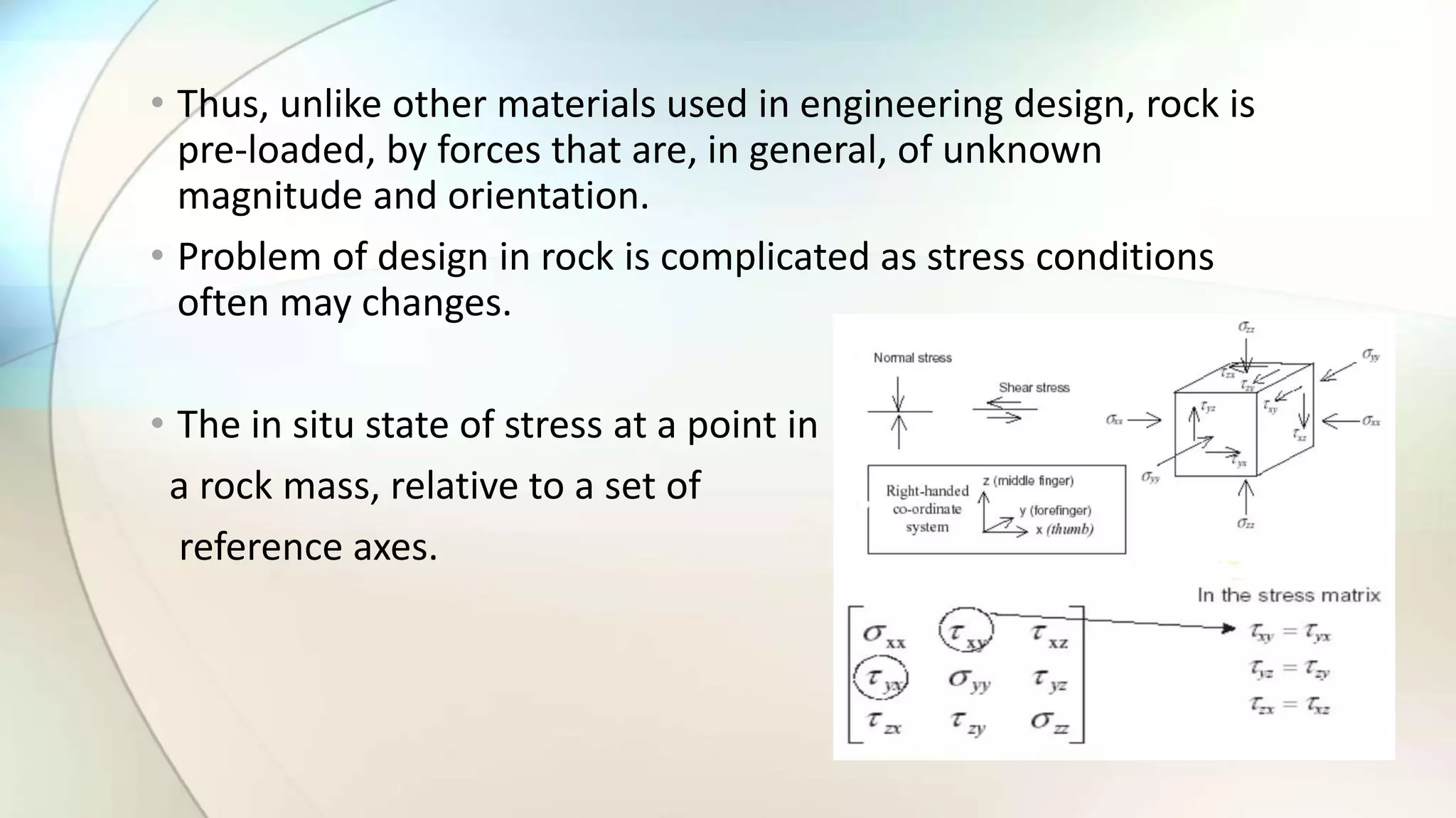
In-situ Stress
- P.Manikiran
BT15MIN016
In situ stress
• Stress is a concept fundamental to Rock Mechanics principles and
applications:
• There is a pre-existing state in the rock mass and we need to
understand it, both directly, and as a stress state applies to analysis
and design.
• During rock excavation, the stress state can change dramatically.
This is because rock, which previously contained stress, has been
removed and the load must be redistributed.
• Stress is not familiar – it is a tensor quantity.
• Thus, unlike other materials used in engineering design, rock is
pre-loaded, by forces that are, in general, of unknown
magnitude and orientation.
• Problem of design in rock is complicated as stress conditions
often may changes.
• The in situ state of stress at a point in
a rock mass, relative to a set of
reference axes.
Stress measurement
Vertical stress
σv = γ.z
σv - vertical stress
γ - unit weight of the overlying rock
z - is the depth below surface.
Horizontal stress
(earlier)
Sheorey (1994)
Ek(GPa)
Factors influencing the in situ state of stress
• The ambient state of stress in an element of rock in the ground
subsurface is determined by both the current loading conditions
in the rock mass, and the stress path defined by its geologic
history.
• Changes in the state of stress in a rock mass may be related to
temperature changes and thermal stress, and chemical and
physicochemical processes such as leaching, precipitation and
recrystallization of constituent minerals.
Stress analysis
-
Stress analysis :
• Basic issues to be considered in the development of a mine
layout include the location and design of the access and service
openings, and the definition of stoping procedures for ore
extraction.
• Mining rock mechanics practice requires effective techniques for
predicting rock mass response to mining activity.
• A particular need is for methods which allow parameter studies
to be undertaken quickly and efficiently, so that a number of
operationally feasible mining options can be evaluated for their
geo mechanical soundness.
• The earliest attempts to develop a predictive capacity for application in
mine design involved studies of physical models of mine structures.
• Their general objective was to identify conditions which might cause
extensive failure in the prototype.
• The difficulty in this procedure is maintaining similitude in the material
properties and the loads applied to model and prototype.
• An additional and major disadvantage of any physical modelling
concerns the expense and time to design, construct and test models
which represent the prototype in sufficient detail to resolve specific
mine design questions.
• The general conclusion is that physical models are inherently limited in
their potential application as a predictive tool in mine design.
• A conventional physical model of a structure yields little or no
information on stresses and displacements in the interior of the
medium.
Physical modelling
• Solutions to the more complex excavation design
problems may usually be obtained by use of
computational procedures.
• The use of these techniques is now firmly embedded in
rock mechanics practice
• Computational methods of stress analysis fall into two
categories –
• > Differential methods and
• > Integral methods.
Computational methods
• In differential methods, the problem domain is divided (discretised)
into a set of subdomains or elements.
• A solution procedure may then be based on numerical
approximations of the governing equations, i.e. the differential
equations of equilibrium, the strain displacement relations and the
stress–strain equations, as in classical finite difference methods.
• The characteristic of integral methods of stress analysis is that a
problem is specified and solved in terms of surface values of the
field variables of traction and displacement.
• Since the problem boundary only is defined and discretised, the so
called boundary element methods of analysis effectively provide a
unit reduction in the dimensional order of a problem.
• The implication is a significant advantage in computational
efficiency, compared with the differential methods.
Three computational methods of stress analysis:
Boundary element method.
Finite element method.
Distinct element method.
Flat jack method
Overcoring method
Flat jack method
• A flat jack is comprised of two metal sheets placed together and
welded around their periphery.
• A feeder tube inserted in the middle allows the flat jack to be
pressurized with oil or water.
• The flat jack method involves the placement of two pins fixed into
the wall of an excavation.
• The distance ‘d’ is then measured accurately
• A slot is cut into the rock between the pins. If the normal stress is
compressive, the pins will move together as the slot is cut .
• The flat jack is then placed and grouted into the slot.
• A narrow slit (35-50mm) is cut. Prior to that deformation
measuring pins are fixed into the narrow holes drilled into the
rock. Due to construction of slot, stress relief takes place. A
hydraulic flat jack is inserted and inflated till the pins returns to
the pre slot values.
The main limitation of the Flat Jack test
• minimum 6 number of tests to be required at different locations
• the size of the flat jack in relation to the size of the rock mass
• assumption of elastic recovery,
• error due to stress concentration/redistribution due to driving of tunnels and
• the test cannot be carried out at appreciable depth from rock surface.
Overcoring method
• Overcoring methods are also in practice to determine the in situ
stresses of rock mass, which involves drilling a large diameter hole
(60-150 mm) in the volume of rock, sufficiently at a distance so that
the effect of the excavation or ground surface will be negligible.
• It will be followed by the small pilot hole (usually ‘EX’ size) at the end
of larger hole. The pilot and large diameter holes must be as
concentric as possible.
• Pilot hole length vary between 300 and 500 mm. The large diameter
hole is resumed, partially or totally relieving stresses and strains
within the cylinder of rock that is formed. The changes in strains or
displacements are then recorded.
• Followed by overcoring, the recovered overcore is often tested to
determine the elastic properties of the rock.
CSIRO HI Cell
• Overcoring with the CSIRO cell is generally performed at depths
within 30m from working faces. The cell fits in an ‘EX’ diameter
hole (38 mm). The cell is glued to the walls of the pilot hole using a
1 mm thick layer of glue.
• The cell contains four, three-component strain rosettes 120°apart.
The strain gauges are 10 mm long. Two strain gauges are parallel to
the axis of the cell and three gauges measure tangential strains.
• The main advantage of the CSIRO cell is that it can be used to
determine the complete stress field in one borehole only.
• At the same time disadvantages of the CSIRO cell are; (1) it
requires long unbroken overcore (2) the cell is not recoverable
until recently. Upon overcoring, the elastic modulus of the rock is
determined by biaxial testing of the recovered overcore containing
the CSIRO cell.

In situ stress

  • 1.
  • 2.
    In situ stress •Stress is a concept fundamental to Rock Mechanics principles and applications: • There is a pre-existing state in the rock mass and we need to understand it, both directly, and as a stress state applies to analysis and design. • During rock excavation, the stress state can change dramatically. This is because rock, which previously contained stress, has been removed and the load must be redistributed. • Stress is not familiar – it is a tensor quantity.
  • 3.
    • Thus, unlikeother materials used in engineering design, rock is pre-loaded, by forces that are, in general, of unknown magnitude and orientation. • Problem of design in rock is complicated as stress conditions often may changes. • The in situ state of stress at a point in a rock mass, relative to a set of reference axes.
  • 4.
    Stress measurement Vertical stress σv= γ.z σv - vertical stress γ - unit weight of the overlying rock z - is the depth below surface. Horizontal stress (earlier) Sheorey (1994) Ek(GPa)
  • 5.
    Factors influencing thein situ state of stress • The ambient state of stress in an element of rock in the ground subsurface is determined by both the current loading conditions in the rock mass, and the stress path defined by its geologic history. • Changes in the state of stress in a rock mass may be related to temperature changes and thermal stress, and chemical and physicochemical processes such as leaching, precipitation and recrystallization of constituent minerals.
  • 6.
  • 7.
    Stress analysis : •Basic issues to be considered in the development of a mine layout include the location and design of the access and service openings, and the definition of stoping procedures for ore extraction. • Mining rock mechanics practice requires effective techniques for predicting rock mass response to mining activity. • A particular need is for methods which allow parameter studies to be undertaken quickly and efficiently, so that a number of operationally feasible mining options can be evaluated for their geo mechanical soundness.
  • 8.
    • The earliestattempts to develop a predictive capacity for application in mine design involved studies of physical models of mine structures. • Their general objective was to identify conditions which might cause extensive failure in the prototype. • The difficulty in this procedure is maintaining similitude in the material properties and the loads applied to model and prototype. • An additional and major disadvantage of any physical modelling concerns the expense and time to design, construct and test models which represent the prototype in sufficient detail to resolve specific mine design questions. • The general conclusion is that physical models are inherently limited in their potential application as a predictive tool in mine design. • A conventional physical model of a structure yields little or no information on stresses and displacements in the interior of the medium. Physical modelling
  • 9.
    • Solutions tothe more complex excavation design problems may usually be obtained by use of computational procedures. • The use of these techniques is now firmly embedded in rock mechanics practice • Computational methods of stress analysis fall into two categories – • > Differential methods and • > Integral methods. Computational methods
  • 10.
    • In differentialmethods, the problem domain is divided (discretised) into a set of subdomains or elements. • A solution procedure may then be based on numerical approximations of the governing equations, i.e. the differential equations of equilibrium, the strain displacement relations and the stress–strain equations, as in classical finite difference methods. • The characteristic of integral methods of stress analysis is that a problem is specified and solved in terms of surface values of the field variables of traction and displacement. • Since the problem boundary only is defined and discretised, the so called boundary element methods of analysis effectively provide a unit reduction in the dimensional order of a problem. • The implication is a significant advantage in computational efficiency, compared with the differential methods.
  • 11.
    Three computational methodsof stress analysis: Boundary element method. Finite element method. Distinct element method.
  • 12.
  • 13.
    Flat jack method •A flat jack is comprised of two metal sheets placed together and welded around their periphery. • A feeder tube inserted in the middle allows the flat jack to be pressurized with oil or water. • The flat jack method involves the placement of two pins fixed into the wall of an excavation. • The distance ‘d’ is then measured accurately • A slot is cut into the rock between the pins. If the normal stress is compressive, the pins will move together as the slot is cut . • The flat jack is then placed and grouted into the slot. • A narrow slit (35-50mm) is cut. Prior to that deformation measuring pins are fixed into the narrow holes drilled into the rock. Due to construction of slot, stress relief takes place. A hydraulic flat jack is inserted and inflated till the pins returns to the pre slot values.
  • 15.
    The main limitationof the Flat Jack test • minimum 6 number of tests to be required at different locations • the size of the flat jack in relation to the size of the rock mass • assumption of elastic recovery, • error due to stress concentration/redistribution due to driving of tunnels and • the test cannot be carried out at appreciable depth from rock surface.
  • 16.
    Overcoring method • Overcoringmethods are also in practice to determine the in situ stresses of rock mass, which involves drilling a large diameter hole (60-150 mm) in the volume of rock, sufficiently at a distance so that the effect of the excavation or ground surface will be negligible. • It will be followed by the small pilot hole (usually ‘EX’ size) at the end of larger hole. The pilot and large diameter holes must be as concentric as possible. • Pilot hole length vary between 300 and 500 mm. The large diameter hole is resumed, partially or totally relieving stresses and strains within the cylinder of rock that is formed. The changes in strains or displacements are then recorded. • Followed by overcoring, the recovered overcore is often tested to determine the elastic properties of the rock.
  • 18.
    CSIRO HI Cell •Overcoring with the CSIRO cell is generally performed at depths within 30m from working faces. The cell fits in an ‘EX’ diameter hole (38 mm). The cell is glued to the walls of the pilot hole using a 1 mm thick layer of glue. • The cell contains four, three-component strain rosettes 120°apart. The strain gauges are 10 mm long. Two strain gauges are parallel to the axis of the cell and three gauges measure tangential strains. • The main advantage of the CSIRO cell is that it can be used to determine the complete stress field in one borehole only. • At the same time disadvantages of the CSIRO cell are; (1) it requires long unbroken overcore (2) the cell is not recoverable until recently. Upon overcoring, the elastic modulus of the rock is determined by biaxial testing of the recovered overcore containing the CSIRO cell.