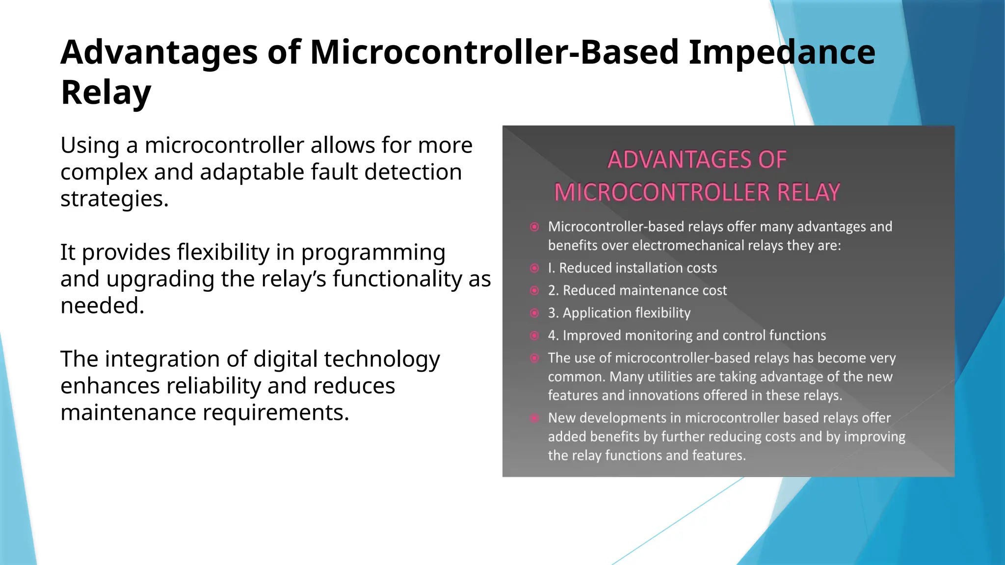
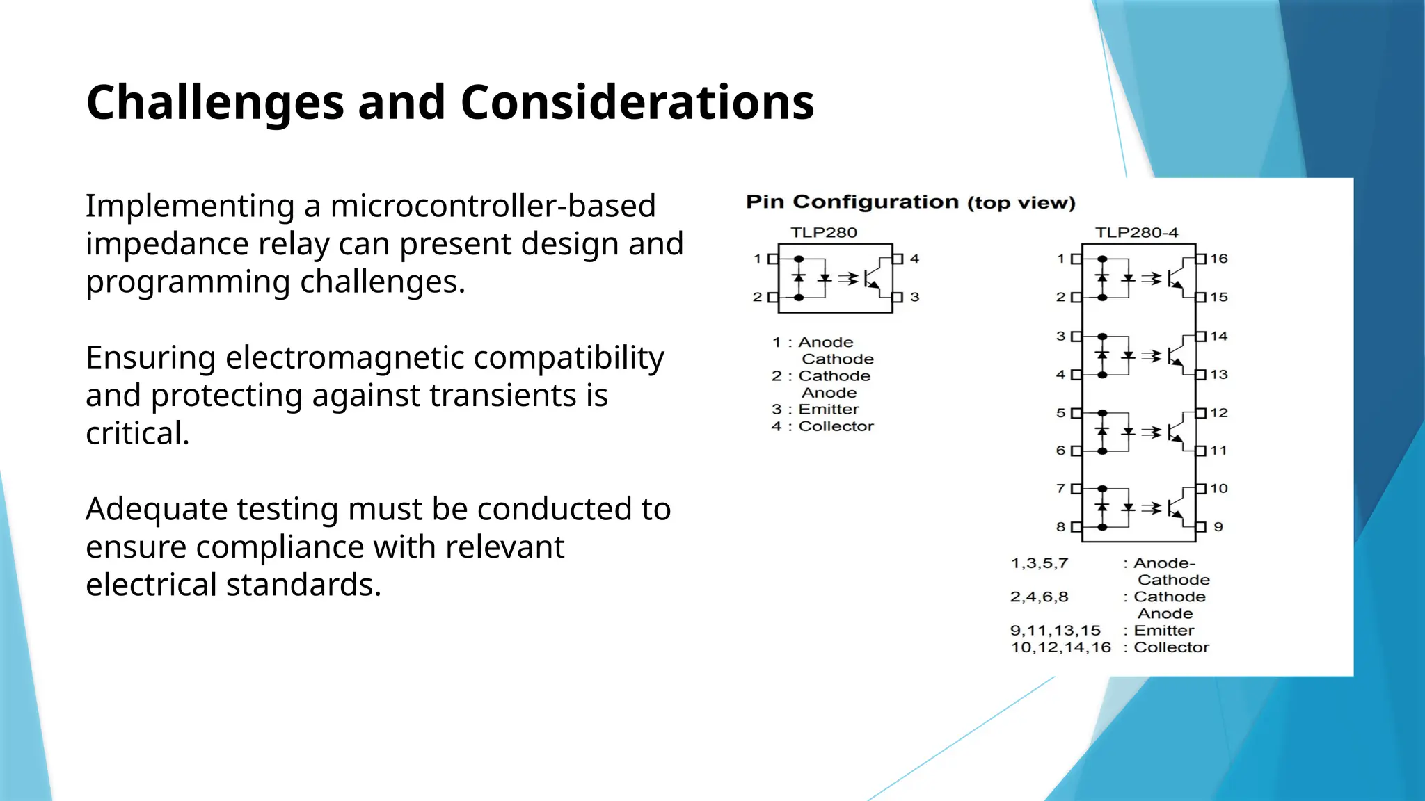
IMPLEMENTATION OF
MICROCONTROLLER (89S52)
BASED IMPEDANCE RELAY
PRESENTED BY:
Shashank S
(1BG22EE415)
Introduction to Impedance Relay
Impedance relays are protective devices
used in electrical systems to detect
faults.
They measure the impedance of the
circuit and provide an indication of fault
conditions.
The implementation of a microcontroller
enhances the functionality and reliability
of these relays.
Overview of Microcontroller 89S52
The 89S52 is an 8-bit microcontroller
from the 8051 family, known for its
versatility.
It features 8 KB of ROM, 256 bytes of
RAM, and various I/O ports for
interfacing.
Its programmable capabilities make it
suitable for applications such as
impedance relays.
Working Principle of Impedance Relay
Impedance relays operate by calculating
the ratio of voltage to current during
fault conditions.
They utilize a predefined impedance
setting to determine if the fault is within
the protected zone.
This method allows for selective tripping
and enhances system stability during
faults.
Circuit Design Overview
The circuit design involves interfacing
the 89S52 microcontroller with voltage
and current sensors.
Operational amplifiers are often used to
scale and condition the sensor outputs.
A relay driver circuit is also included to
control the relay operation based on
microcontroller commands.
Software Development for Impedance Calculation
The software for the 89S52 is developed
using embedded C or assembly
language.
It includes algorithms for real-time
impedance calculation based on sensor
inputs.
The code also manages relay activation
and deactivation based on fault
detection criteria.
Fault Detection Algorithms
Various fault detection algorithms can be
implemented to enhance reliability.
These algorithms may include threshold
settings and time-delay for transient
conditions.
They are crucial for minimizing false
tripping and ensuring accurate fault
identification.
Testing and Calibration
Testing involves simulating fault
conditions to verify the relay's response.
Calibration of the sensors is essential to
ensure accurate measurement of voltage
and current.
Documenting the test results helps in
fine-tuning the system for optimal
performance.
Advantages of Microcontroller-Based Impedance
Relay
Using a microcontroller allows for more
complex and adaptable fault detection
strategies.
It provides flexibility in programming
and upgrading the relay’s functionality as
needed.
The integration of digital technology
enhances reliability and reduces
maintenance requirements.
Challenges and Considerations
Implementing a microcontroller-based
impedance relay can present design and
programming challenges.
Ensuring electromagnetic compatibility
and protecting against transients is
critical.
Adequate testing must be conducted to
ensure compliance with relevant
electrical standards.
Conclusion and Future Work
Microcontroller-based impedance relays
represent a significant advancement in
protective relay technology.
Future work may focus on enhancing
communication protocols and
integrating IoT capabilities.
Continued research and development
will lead to more intelligent and efficient
protection systems.
implementation of microcontroller based impedence relay

implementation of microcontroller based impedence relay

  • 1.
    IMPLEMENTATION OF MICROCONTROLLER (89S52) BASEDIMPEDANCE RELAY PRESENTED BY: Shashank S (1BG22EE415)
  • 2.
    Introduction to ImpedanceRelay Impedance relays are protective devices used in electrical systems to detect faults. They measure the impedance of the circuit and provide an indication of fault conditions. The implementation of a microcontroller enhances the functionality and reliability of these relays.
  • 3.
    Overview of Microcontroller89S52 The 89S52 is an 8-bit microcontroller from the 8051 family, known for its versatility. It features 8 KB of ROM, 256 bytes of RAM, and various I/O ports for interfacing. Its programmable capabilities make it suitable for applications such as impedance relays.
  • 4.
    Working Principle ofImpedance Relay Impedance relays operate by calculating the ratio of voltage to current during fault conditions. They utilize a predefined impedance setting to determine if the fault is within the protected zone. This method allows for selective tripping and enhances system stability during faults.
  • 5.
    Circuit Design Overview Thecircuit design involves interfacing the 89S52 microcontroller with voltage and current sensors. Operational amplifiers are often used to scale and condition the sensor outputs. A relay driver circuit is also included to control the relay operation based on microcontroller commands.
  • 6.
    Software Development forImpedance Calculation The software for the 89S52 is developed using embedded C or assembly language. It includes algorithms for real-time impedance calculation based on sensor inputs. The code also manages relay activation and deactivation based on fault detection criteria.
  • 7.
    Fault Detection Algorithms Variousfault detection algorithms can be implemented to enhance reliability. These algorithms may include threshold settings and time-delay for transient conditions. They are crucial for minimizing false tripping and ensuring accurate fault identification.
  • 8.
    Testing and Calibration Testinginvolves simulating fault conditions to verify the relay's response. Calibration of the sensors is essential to ensure accurate measurement of voltage and current. Documenting the test results helps in fine-tuning the system for optimal performance.
  • 9.
    Advantages of Microcontroller-BasedImpedance Relay Using a microcontroller allows for more complex and adaptable fault detection strategies. It provides flexibility in programming and upgrading the relay’s functionality as needed. The integration of digital technology enhances reliability and reduces maintenance requirements.
  • 10.
    Challenges and Considerations Implementinga microcontroller-based impedance relay can present design and programming challenges. Ensuring electromagnetic compatibility and protecting against transients is critical. Adequate testing must be conducted to ensure compliance with relevant electrical standards.
  • 11.
    Conclusion and FutureWork Microcontroller-based impedance relays represent a significant advancement in protective relay technology. Future work may focus on enhancing communication protocols and integrating IoT capabilities. Continued research and development will lead to more intelligent and efficient protection systems.

Editor's Notes

  • #2 Image source: https://www.electricity-magnetism.org/impedance-relay/
  • #3 Image source: https://www.mytechnocare.com/product/40-pin-ic-base-dip-8051/?add-to-cart=1087
  • #4 Image source: https://www.electricaldeck.com/2021/10/distance-relay-or-impedance-relay-its-working-principle-and-types.html
  • #5 Image source: https://circuitdigest.com/microcontroller-projects/lcd-interfacing-with-8051-microcontroller-89s52
  • #6 Image source: https://www.instructables.com/89S52-Programmer-Using-Arduino-Uno/
  • #7 Image source: https://www.researchgate.net/figure/Fault-detection-algorithm_fig4_350482904
  • #8 Image source: https://wiki.testguy.net/t/ground-fault-protection-systems-performance-testing-basics/78?r=279-Ground-Fault-Protection-Systems-Performance-Testing-Basics&s=5f6f6eda522ea6979676ae64d7c8c274
  • #9 Image source: https://www.slideserve.com/kaethe/microcontroller-based-multifunction-relay
  • #10 Image source: https://guidedataaudra.z19.web.core.windows.net/microcontroller-based-overcurrent-relay-circuit-diagram.html
  • #11 Image source: https://mavink.com/explore/Microcontroller-Architecture