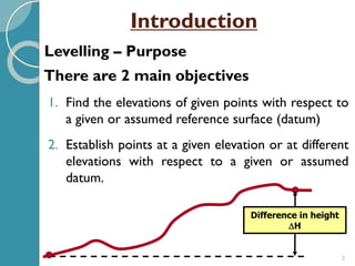
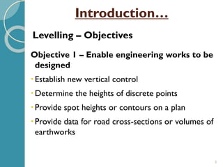
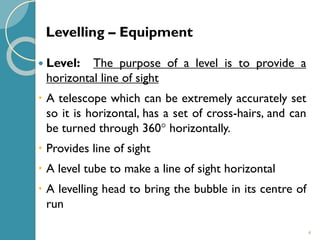
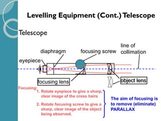
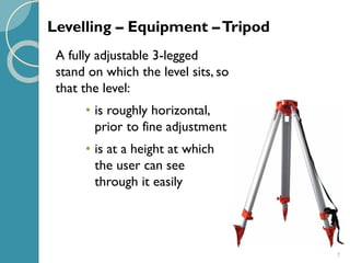
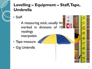
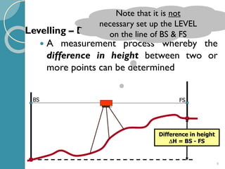
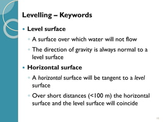
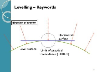
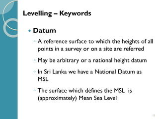
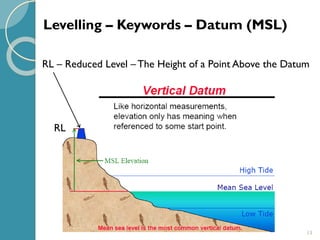
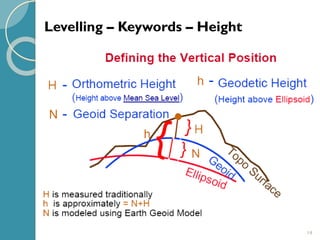
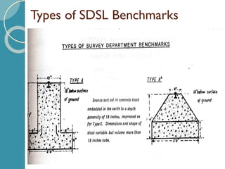
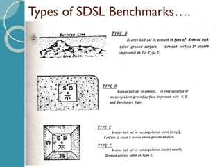
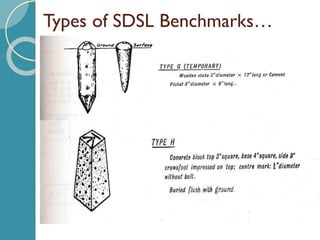
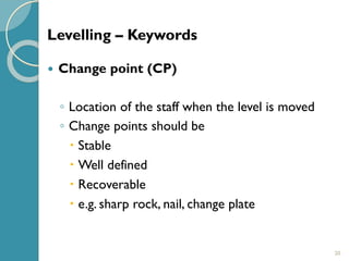
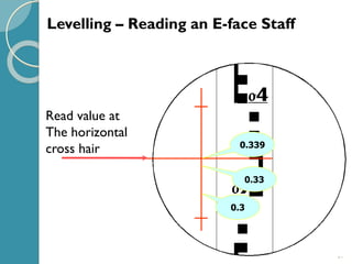
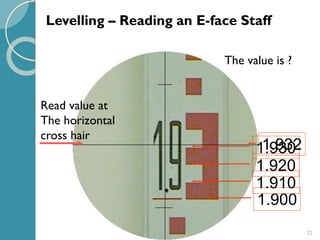
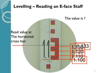
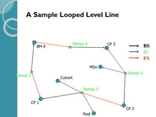
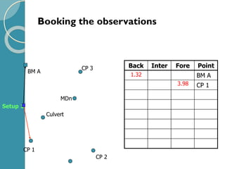
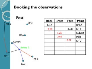
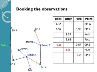
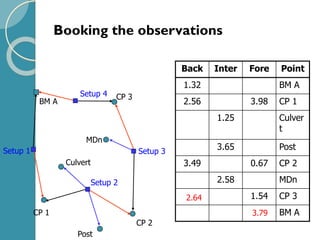
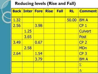
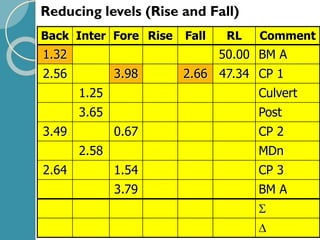
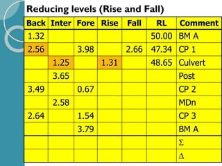
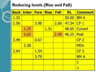
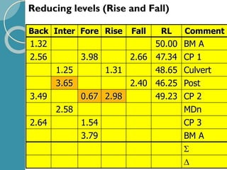
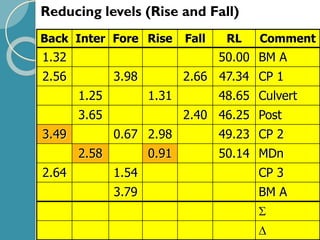
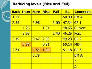
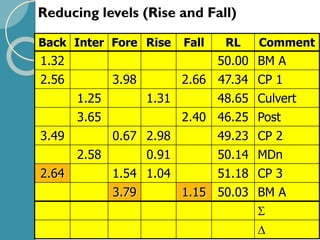
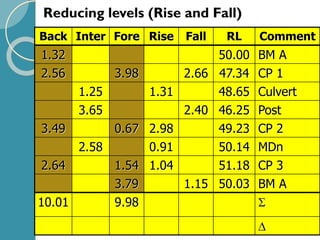
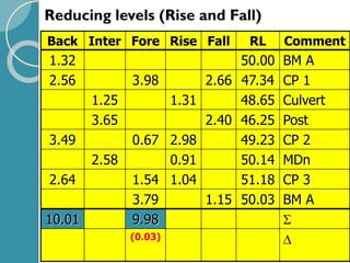
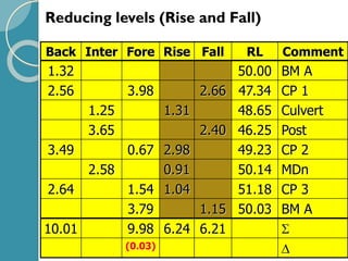
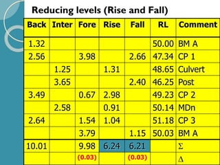
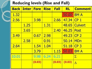
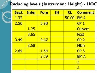
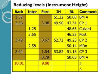
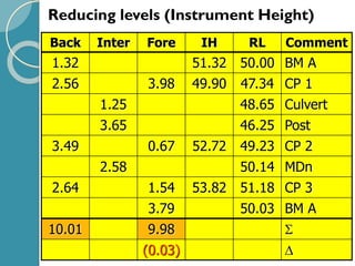
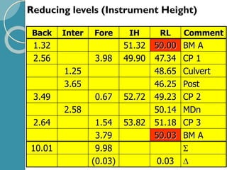
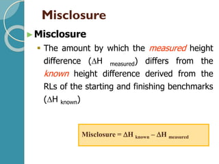
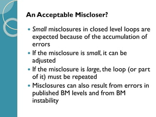
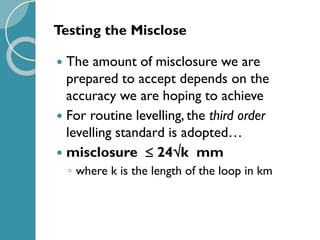
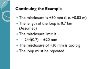
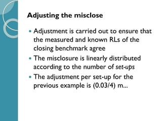
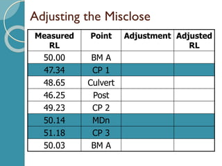
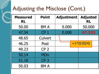
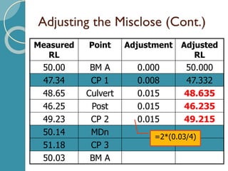
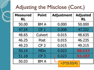
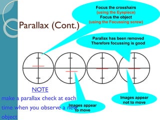
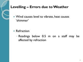
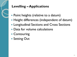
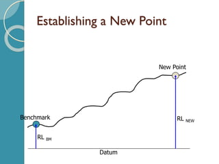
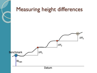
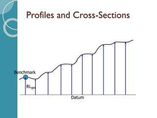
2. 2
There are 2 main objectives
1. Find the elevations of given points with respect to
a given or assumed reference surface (datum)
2. Establish points at a given elevation or at different
elevations with respect to a given or assumed
datum.
Difference in height
H
Levelling – Purpose
Introduction
3. 3
Objective 1 – Enable engineering works to be
designed
Establish new vertical control
Determine the heights of discrete points
Provide spot heights or contours on a plan
Provide data for road cross-sections or volumes of
earthworks
Levelling – Objectives
Introduction…
4. 4
Level: The purpose of a level is to provide a
horizontal line of sight
A telescope which can be extremely accurately set
so it is horizontal, has a set of cross-hairs, and can
be turned through 360 horizontally.
Provides line of sight
A level tube to make a line of sight horizontal
A levelling head to bring the bubble in its centre of
run
Levelling – Equipment
5. Levelling Equipment (Cont.)Telescope
Telescope
eyepiece
object lensobject lensfocusing lens
diaphragm focusing screw
line of
collimation
Focusing:
1. Rotate eyepiece to give a sharp,
clear image of the cross hairs
2. Rotate focusing screw to give a
sharp, clear image of the object
being observed.
The aim of focusing is
to remove (eliminate)
PARALLAX
6. 6
Objective 2 - Required in the setting out of all
kinds of engineering works
Provide a level or inclined plane to set out of
construction work
Levelling – Objectives
7. 7
A fully adjustable 3-legged
stand on which the level sits, so
that the level:
• is roughly horizontal,
prior to fine adjustment
• is at a height at which
the user can see
through it easily
Levelling – Equipment –Tripod
8. 8
Staff
A measuring stick, usually 4m tall, and clearly
marked in divisions of 10 mm (allowing
readings to be taken to 1mm by
interpolation), which is held vertically
Tape measure
Gig Umbrella
Levelling – Equipment – Staff,Tape,
Umbrella
9. 9
BS FS
A measurement process whereby the
difference in height between two or
more points can be determined
Difference in height
H = BS - FS
Levelling – Definition
Note that it is not
necessary set up the LEVEL
on the line of BS & FS
10. 10
Level surface
◦ A surface over which water will not flow
◦ The direction of gravity is always normal to a
level surface
Horizontal surface
◦ A horizontal surface will be tangent to a level
surface
◦ Over short distances (<100 m) the horizontal
surface and the level surface will coincide
Levelling – Keywords
12. 12
Datum
◦ A reference surface to which the heights of all
points in a survey or on a site are referred
◦ May be arbitrary or a national height datum
◦ In Sri Lanka we have a National Datum as
MSL
◦ The surface which defines the MSL is
(approximately) Mean Sea Level
Levelling – Keywords
15. 15
Reduced Level (RL)
◦ The height of a point above the datum
Benchmark (BM)
◦ A stable reference point of known RL
◦ Usually used as the starting and finishing point
when levelling
Temporary Bench Mark (TBM)
◦ A point placed (e.g. peg, nail, spike) to provide a
temporary reference point
Levelling – Keywords
19. 19
Backsight (BS)
◦ Always the first reading from a new
instrument station
Foresight (FS)
◦ Always the last reading from the current
instrument station
Intermediate sight (IS)
◦ Any sighting that is not a backsight or
foresight
Levelling – Keywords
20. 20
Change point (CP)
◦ Location of the staff when the level is moved
◦ Change points should be
Stable
Well defined
Recoverable
e.g. sharp rock, nail, change plate
Levelling – Keywords
24. 24
Always commence and finish a level run on a
Benchmark (BM or TBM)
Keep foresight and backsight distances as equal as
possible
Keep lines of sight short (normally < 50m)
Use stable, well defined change points
Levelling – Rules
25. A Sample Looped Level Line
Setup 1
Setup 2
Setup 3
Setup 4
BS
IS
FS
BM A
CP 1
CP 2
CP 3
Culvert
Post
MDn
27. Post
Booking the observations
BM A
CP 1
CP 2
CP 3
Culvert
MDn
Setup 2
Back Inter Fore Point
1.32 BM A
3.98 CP 1
Culvert
Post
CP 2
2.56
1.25
3.65
0.67
Post
28. Booking the observations
BM A
CP 1
CP 2
CP 3
Culvert
MDn
Setup 2
Setup 3
Back Inter Fore Point
1.32 BM A
2.56 3.98 CP 1
1.25 Kerb
3.65 Post
0.67 CP 2
MDn
CP 3
3.49
2.58
1.54
Post
Setup 1
29. Booking the observations
BM A
CP 1
CP 2
CP 3
Culvert
Post
MDn
Setup 1
Setup 4
Setup 2
Setup 3
Back Inter Fore Point
1.32 BM A
2.56 3.98 CP 1
1.25 Culver
t
3.65 Post
3.49 0.67 CP 2
2.58 MDn
1.54 CP 3
BM A
2.64
3.79
30. Reducing levels (Rise and Fall)
Back Inter Fore Rise Fall RL Comment
1.32 50.00 BM A
2.56 3.98 CP 1
1.25 Culvert
3.65 Post
3.49 0.67 CP 2
2.58 MDn
2.64 1.54 CP 3
3.79 BM A
31. Reducing levels (Rise and Fall)
Back Inter Fore Rise Fall RL Comment
1.32 50.00 BM A
2.56 3.98 2.66 47.34 CP 1
1.25 Culvert
3.65 Post
3.49 0.67 CP 2
2.58 MDn
2.64 1.54 CP 3
3.79 BM A
32. Reducing levels (Rise and Fall)
Back Inter Fore Rise Fall RL Comment
1.32 50.00 BM A
2.56 3.98 2.66 47.34 CP 1
1.25 1.31 48.65 Culvert
3.65 Post
3.49 0.67 CP 2
2.58 MDn
2.64 1.54 CP 3
3.79 BM A
33. Reducing levels (Rise and Fall)
Back Inter Fore Rise Fall RL Comment
1.32 50.00 BM A
2.56 3.98 2.66 47.34 CP 1
1.25 1.31 48.65 Culvert
3.65 2.40 46.25 Post
3.49 0.67 CP 2
2.58 MDn
2.64 1.54 CP 3
3.79 BM A
34. Reducing levels (Rise and Fall)
Back Inter Fore Rise Fall RL Comment
1.32 50.00 BM A
2.56 3.98 2.66 47.34 CP 1
1.25 1.31 48.65 Culvert
3.65 2.40 46.25 Post
3.49 0.67 2.98 49.23 CP 2
2.58 MDn
2.64 1.54 CP 3
3.79 BM A
35. Reducing levels (Rise and Fall)
Back Inter Fore Rise Fall RL Comment
1.32 50.00 BM A
2.56 3.98 2.66 47.34 CP 1
1.25 1.31 48.65 Culvert
3.65 2.40 46.25 Post
3.49 0.67 2.98 49.23 CP 2
2.58 0.91 50.14 MDn
2.64 1.54 CP 3
3.79 BM A
36. Reducing levels (Rise and Fall)
Back Inter Fore Rise Fall RL Comment
1.32 50.00 BM A
2.56 3.98 2.66 47.34 CP 1
1.25 1.31 48.65 Culvert
3.65 2.40 46.25 Post
3.49 0.67 2.98 49.23 CP 2
2.58 0.91 50.14 MDn
2.64 1.54 1.04 51.18 CP 3
3.79 BM A
37. Reducing levels (Rise and Fall)
Back Inter Fore Rise Fall RL Comment
1.32 50.00 BM A
2.56 3.98 2.66 47.34 CP 1
1.25 1.31 48.65 Culvert
3.65 2.40 46.25 Post
3.49 0.67 2.98 49.23 CP 2
2.58 0.91 50.14 MDn
2.64 1.54 1.04 51.18 CP 3
3.79 1.15 50.03 BM A
38. Reducing levels (Rise and Fall)
Back Inter Fore Rise Fall RL Comment
1.32 50.00 BM A
2.56 3.98 2.66 47.34 CP 1
1.25 1.31 48.65 Culvert
3.65 2.40 46.25 Post
3.49 0.67 2.98 49.23 CP 2
2.58 0.91 50.14 MDn
2.64 1.54 1.04 51.18 CP 3
3.79 1.15 50.03 BM A
10.01 9.98
39. Reducing levels (Rise and Fall)
Back Inter Fore Rise Fall RL Comment
1.32 50.00 BM A
2.56 3.98 2.66 47.34 CP 1
1.25 1.31 48.65 Culvert
3.65 2.40 46.25 Post
3.49 0.67 2.98 49.23 CP 2
2.58 0.91 50.14 MDn
2.64 1.54 1.04 51.18 CP 3
3.79 1.15 50.03 BM A
10.01 9.98
(0.03)
40. Reducing levels (Rise and Fall)
Back Inter Fore Rise Fall RL Comment
1.32 50.00 BM A
2.56 3.98 2.66 47.34 CP 1
1.25 1.31 48.65 Culvert
3.65 2.40 46.25 Post
3.49 0.67 2.98 49.23 CP 2
2.58 0.91 50.14 MDn
2.64 1.54 1.04 51.18 CP 3
3.79 1.15 50.03 BM A
10.01 9.98 6.24 6.21
(0.03)
41. Reducing levels (Rise and Fall)
Back Inter Fore Rise Fall RL Comment
1.32 50.00 BM A
2.56 3.98 2.66 47.34 CP 1
1.25 1.31 48.65 Culvert
3.65 2.40 46.25 Post
3.49 0.67 2.98 49.23 CP 2
2.58 0.91 50.14 MDn
2.64 1.54 1.04 51.18 CP 3
3.79 1.15 50.03 BM A
10.01 9.98 6.24 6.21
(0.03) (0.03)
42. Reducing levels (Rise and Fall)
Back Inter Fore Rise Fall RL Comment
1.32 50.00 BM A
2.56 3.98 2.66 47.34 CP 1
1.25 1.31 48.65 Culvert
3.65 2.40 46.25 Post
3.49 0.67 2.98 49.23 CP 2
2.58 0.91 50.14 MDn
2.64 1.54 1.04 51.18 CP 3
3.79 1.15 50.03 BM A
10.01 9.98 6.24 6.21
(0.03) (0.03) (0.03)
43. Back Inter Fore IH RL Comment
1.32 50.00 BM A
2.56 3.98 CP 1
1.25 Culvert
3.65 Post
3.49 0.67 CP 2
2.58 MDn
2.64 1.54 CP 3
3.79 BM A
Reducing levels (Instrument Height) - HOC
44. Back Inter Fore IH RL Comment
1.32 51.32 50.00 BM A
2.56 3.98 49.90 47.34 CP 1
1.25 48.65 Culvert
3.65 46.25 Post
3.49 0.67 52.72 49.23 CP 2
2.58 50.14 MDn
2.64 1.54 53.82 51.18 CP 3
3.79 50.03 BM A
10.01 9.98
Reducing levels (Instrument Height)
45. Back Inter Fore IH RL Comment
1.32 51.32 50.00 BM A
2.56 3.98 49.90 47.34 CP 1
1.25 48.65 Culvert
3.65 46.25 Post
3.49 0.67 52.72 49.23 CP 2
2.58 50.14 MDn
2.64 1.54 53.82 51.18 CP 3
3.79 50.03 BM A
10.01 9.98
(0.03)
Reducing levels (Instrument Height)
46. Back Inter Fore IH RL Comment
1.32 51.32 50.00 BM A
2.56 3.98 49.90 47.34 CP 1
1.25 48.65 Culvert
3.65 46.25 Post
3.49 0.67 52.72 49.23 CP 2
2.58 50.14 MDn
2.64 1.54 53.82 51.18 CP 3
3.79 50.03 BM A
10.01 9.98
(0.03) 0.03
Reducing levels (Instrument Height)
47. Misclosure
►Misclosure
▪ The amount by which the measured height
difference (H measured) differs from the
known height difference derived from the
RLs of the starting and finishing benchmarks
(H known)
Misclosure = H known – H measured
48. An Acceptable Miscloser?
Small misclosures in closed level loops are
expected because of the accumulation of
errors
If the misclosure is small, it can be
adjusted
If the misclosure is large, the loop (or part
of it) must be repeated
Misclosures can also result from errors in
published BM levels and from BM
instability
49. Testing the Misclose
The amount of misclosure we are
prepared to accept depends on the
accuracy we are hoping to achieve
For routine levelling, the third order
levelling standard is adopted…
misclosure 24k mm
◦ where k is the length of the loop in km
50. Continuing the Example
The misclosure is +30 mm (i. e. +0.03 m)
The length of the loop is 0.7 km
(Assumed)
The misclosure limit is…
24(0.7) = ±20 mm
The misclosure of +30 mm is too big
The loop must be repeated
51. Adjusting the misclose
Adjustment is carried out to ensure that
the measured and known RLs of the
closing benchmark agree
The misclosure is linearly distributed
according to the number of set-ups
The adjustment per set-up for the
previous example is (0.03/4) m...
53. Adjusting the Misclose (Cont.)
Measured
RL
Point Adjustment Adjusted
RL
50.00 BM A 0.000 50.000
47.34 CP 1 0.008 47.332
48.65 Culvert
46.25 Post
49.23 CP 2
50.14 MDn
51.18 CP 3
50.03 BM A
=1*(0.03/4)
54. Adjusting the Misclose (Cont.)
Measured
RL
Point Adjustment Adjusted
RL
50.00 BM A 0.000 50.000
47.34 CP 1 0.008 47.332
48.65 Culvert 0.015 48.635
46.25 Post 0.015 46.235
49.23 CP 2 0.015 49.215
50.14 MDn
51.18 CP 3
50.03 BM A
=2*(0.03/4)
55. Adjusting the Misclose (Cont.)
Measured
RL
Point Adjustment Adjusted
RL
50.00 BM A 0.000 50.000
47.34 CP 1 0.008 47.332
48.65 Culvert 0.015 48.635
46.25 Post 0.015 46.235
49.23 CP 2 0.015 49.215
50.14 MDn 0.023 50.117
51.18 CP 3 0.023 51.157
50.03 BM A =3*(0.03/4)
56. Adjusting the Misclose (Cont.)
Measured
RL
Point Adjustmen
t
Adjusted
RL
50.00 BM A 0.000 50.000
47.34 CP 1 0.008 47.332
48.65 Culvert 0.015 48.635
46.25 Post 0.015 46.235
49.23 CP 2 0.015 49.215
50.14 MDn 0.023 50.117
51.18 CP 3 0.023 51.157
50.03 BM A 0.030 50.000
=4*(0.03/4)
57. Adjusting the Misclose (Cont.)
Measured
RL
Point Adjustment Adjusted
RL
50.00 BM A 0.000 50.000
47.34 CP 1 0.008 47.332
48.65 Culvert 0.015 48.635
46.25 Post 0.015 46.235
49.23 CP 2 0.015 49.215
50.14 MDn 0.023 50.117
51.18 CP 3 0.023 51.157
50.03 BM A 0.030 50.000
58. 58
Parallax
◦ Focus eyepiece on cross-hairs, then focus
telescope on staff
Collimation Error - Line of sight not horizontal
◦ Keep sight lengths from each instrument
position the same
◦ Check collimation error
• Magnetic field effects on Auto Level
Levelling – Errors in the Equipment
59. Parallax
When focussing any optical instrument it
is vitally important that we eliminate
Parallax
Move the eye up and down (or from left
to right) over the eyepiece of the
telescope
If the cross hairs move relative to the
object being observed then Parallax exists
and the focussing is not satisfactory
60. Parallax (Cont.)
Focus the crosshairs
(using the Eyepiece)
Focus the object
(using the Focussing screw)
Images appear
to move
Parallax has been removed
Therefore focussing is good
Images appear
not to move
NOTE
make a parallax check at each
time when you observe a new
object
61. 61
Change point instability
◦ Use stable, well defined, recoverable change points
◦ e.g. sharp rock, nail, change plate
Staff Errors
◦ Zero error - base may be worn - doesn’t matter as
long as same staff is always used
Tripod Errors
◦ Must be stable
Levelling – Errors in the Equipment
62. 62
Staff not vertical
◦ Use pond bubble on staff
Unstable equipment
◦ Watch out for soft ground under tripod or staff
◦ Don’t touch (or kick!) tripod
Levelling – Errors in the Field
63. 63
Keep sightings short to estimate mm on staff
accurately
Double check all readings
Write clearly
Carry out calculation checks
Levelling – Errors in Reading and/or
Booking
64. 64
Wind causes level to vibrate, heat causes
‘shimmer’
Refraction
◦ Readings below 0.5 m on a staff may be
affected by refraction
Levelling – Errors due to Weather
65. 65
Point heights (relative to a datum)
Height differences (independent of datum)
Longitudinal Sections and Cross Sections
Data for volume calculations
Contouring
Setting Out
Levelling – Applications
69. 69
Contour – line drawn on a plan joining all
points of the same height above or below a
datum
Contours cannot cross, split or join other
contours, except in the case of an overhang.
e.g. a cliff.
The height between successive contours –
vertical interval/contour interval
Its value depends on the variation in height
of the area being contoured
Levelling – Contouring
70. 70
Contour interval is kept constant for a plan
or map
Plan spacing between contour line indicates
steepness of slopes
Closely spaced lines indicates a steep gradient
Widely spaced lines indicate a flatter gradient
Levelling – Contouring