Downloaded 23 times


![1.4.1 Agarose gels
Agarose can be used for isoelectric focusing and separation of large
proteins or protein complexes. Agarose is a highly purified polysaccharide
derived from agar. For protein IEF applications, the critical qualities are
low EEO and good clarity at the working concentration. When used in a
thin horizontal format for IEF, agarose gels must be supported on a plas-
tic backing and cooled during electrophoresis.
Agarose is normally purchased as a dry powder. It dissolves when the
suspended powder is heated to near boiling and it remains liquid until the
temperature drops to about 40 ºC, when it gels or “sets.” There are specific
types of agarose that have melting and gelling temperatures considerably
lower than those of standard agarose. These properties improve the recov-
ery of material from a gel after separation for subsequent enzymatic treat-
ments of the separated material.
The pore size and sieving characteristics of a gel are determined by
adjusting the concentration of agarose in the gel. The higher the concen-
tration, the smaller the pore size. Working concentrations are normally
in the range of 0.4–4% w/v.
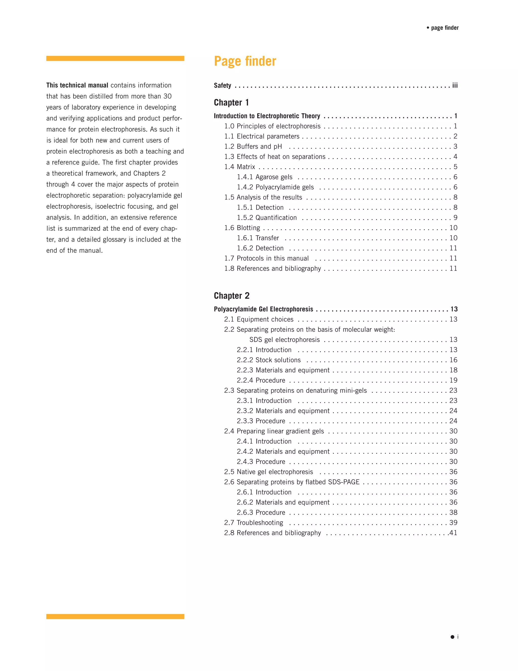
Agarose gels are relatively fragile and should be handled carefully. The
gels are hydrocolloids, held together by hydrogen and hydrophobic bonds,
and tend to be somewhat brittle (Fig 1.5a). An agarose gel should always
be handled with some form of support for the entire gel, such as a tray or
wide spatula, because the gel will break if it bends too far.
1.4.2 Polyacrylamide gels
Polyacrylamide gels are physically tougher than agarose gels. The gel
forms when a mixed solution of acrylamide and cross-linker monomers
co-polymerize into long chains that are covalently cross-linked. The gel
structure is held together by the cross-linker (Fig 1.5b). The most common
cross-linker is N,N'-methylenebisacrylamide (“bis” for short). Other
cross-linkers that can be cleaved after polymerization are available (e.g.
N,N'-bis-[acryloyl]-cystamine can be cleaved by disulphide reducing
agents); they aid in recovering separated species from the gel by allowing
the polymerized acrylamide to be solubilized.
Because polymerization of acrylamide is a free-radical catalyzed reaction,
preparation of polyacrylamide gels is somewhat more complex than that
of agarose gels. Some of the technical issues are discussed in the follow-
ing sections.
Preparing and pouring the monomer solution
Atmospheric oxygen is a free-radical scavenger that can inhibit polymer-
ization. For consistent results the acrylamide monomer solution is
deaerated by purging it with an inert gas or by exposing it to a vacuum
for a few minutes. Preparing solutions with a minimum of stirring, which
introduces air, will reduce oxygen inhibition problems.
tm 80-6013-88 • p6
protein electrophoresis • introduction to electrophoretic theory
Fig 1.5. Agarose and acrylamide gels. (A) Agarose
gels form by noncovalent hydrogen and hydrophobic
bonds between long sugar polymers. (B) Acrylamide
gels have covalent cross-links (•) between polymer
strands.
A B](https://image.slidesharecdn.com/manualeletroforese-160916131413/75/ICSA17-Imunologia-Manual-eletroforese-11-2048.jpg)


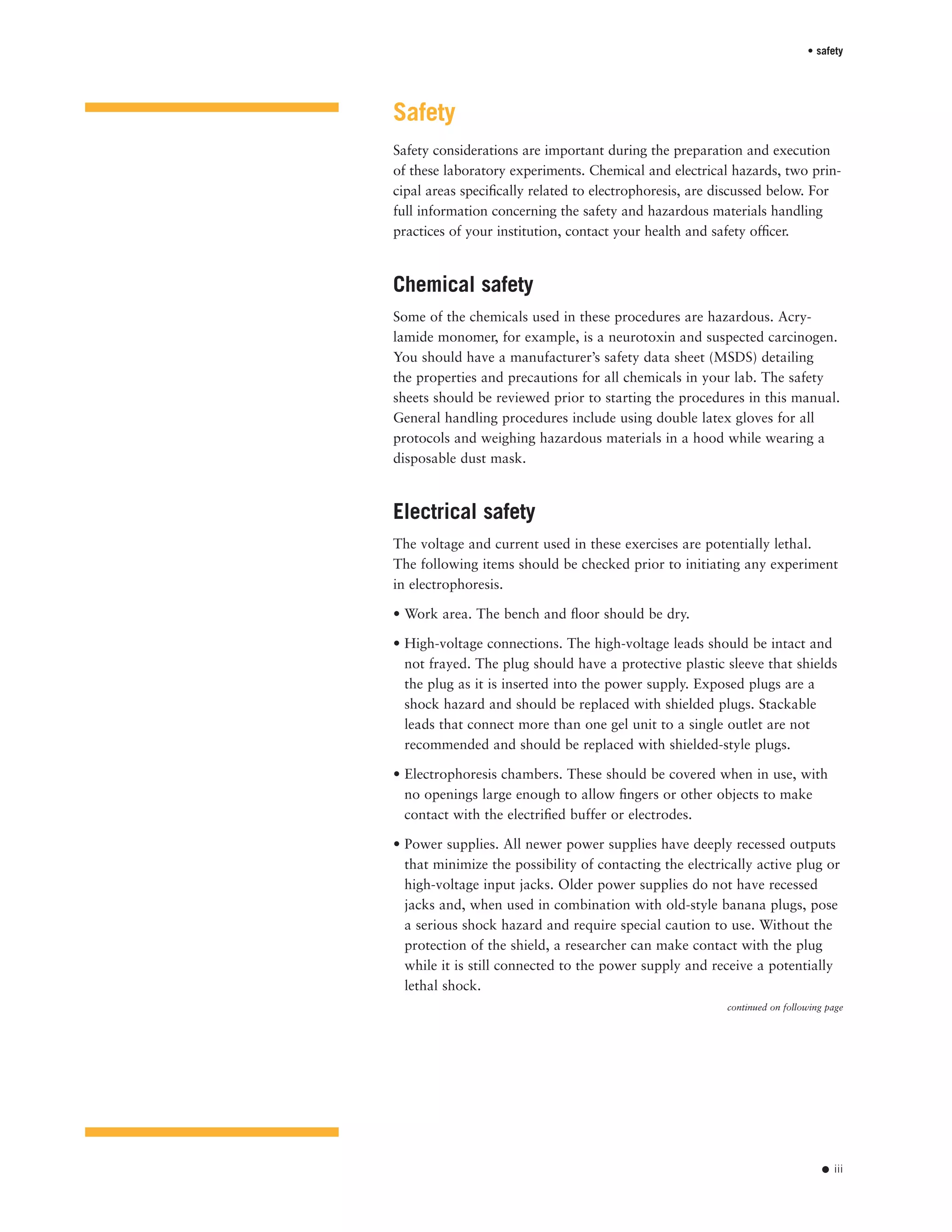
![sizes of unknown species can be estimated by visual comparison to the
standard. For more-accurate estimates, standard band mobilities are used
to generate a calibration curve, then unknown sizes are read off of the
curve. Because the sizes of molecules are not a simple function of distance
moved through a gel, the best estimates of unknown sizes require having
several standards both smaller and larger than the molecule of interest.
Plots of DNA molecule length (in base pairs) as a function of distance are
shown in Figure 1.8. For comparison, protein molecular weight plots are
shown in Figures 4.9 through 4.11.
Isoelectric point
As discussed, electrophoresing amphoteric molecules through a pH gra-
dient results in isoelectric focusing; the molecules stop at the pH equal
to their pI. The pI of an unknown protein can be estimated quickly by
comparing it with standards with known pIs, as described for sizing in
the preceding section. If the pH gradient is formed using soluble buffering
species (ampholytes), the pH of the gel can be measured at desired points
along the surface, using a pH electrode designed for use on moist surfaces.
1.6 Blotting
1.6.1 Transfer
For analysis based on antibody reactivity, the separated molecules need
to be free of the electrophoresis matrix. This can be done by slicing the
gel into segments and then eluting the sample into a buffer, but the
process is slow and the resolution is low. A more efficient method uses a
“blotting” technique. In blotting, the molecules separated on a slab gel
are eluted through the broad face of the gel onto a membrane filter that
binds the molecules as they emerge. The proteins (or nucleic acids) stay
predominantly on the surface of the membrane, where they are accessi-
ble for detection.
The membrane materials used most frequently in blotting are nitrocellu-
lose, various forms of modified and unmodified nylon, and polyvinylidene
difluoride (PVDF). The choice of membrane depends on the type of
analysis and characteristics of the detection system. Nitrocellulose is the
most generally applicable; some nylons do not bind protein reliably.
PVDF is often used when the bound protein will ultimately be analyzed
by automated solid-phase protein sequencing.
The transfer of the sample from the gel to the membrane can be driven
either by capillary flow of buffer or by transverse electrophoresis. The use
of capillary flow to transfer DNA from agarose gels to nitrocellulose was
first described by Southern (1975), hence the name Southern blot. Using
the same method for transfer of RNA is called Northern blotting, and
any blot transfer of proteins is called Western blotting for simple playful
consistency of nomenclature.
protein electrophoresis • introduction to electrophoretic theory
tm 80-6013-88 • p10
800
600
400
200
0
20 60 100 140
distance (mm)
size(basepairs)
1000
500
400
300
200
100A
B
Fig 1.8. Analyzing gels for size information.
(A) Acrylamide DNA gel. (B) Plot of size (bp)
versus distance migrated. (C) Plot of log (size
[bp]) versus distance.
20 60 100 140
distance (mm)
log(size[basepairs])
C
3.00
2.75
2.50
2.25
2.00](https://image.slidesharecdn.com/manualeletroforese-160916131413/75/ICSA17-Imunologia-Manual-eletroforese-15-2048.jpg)


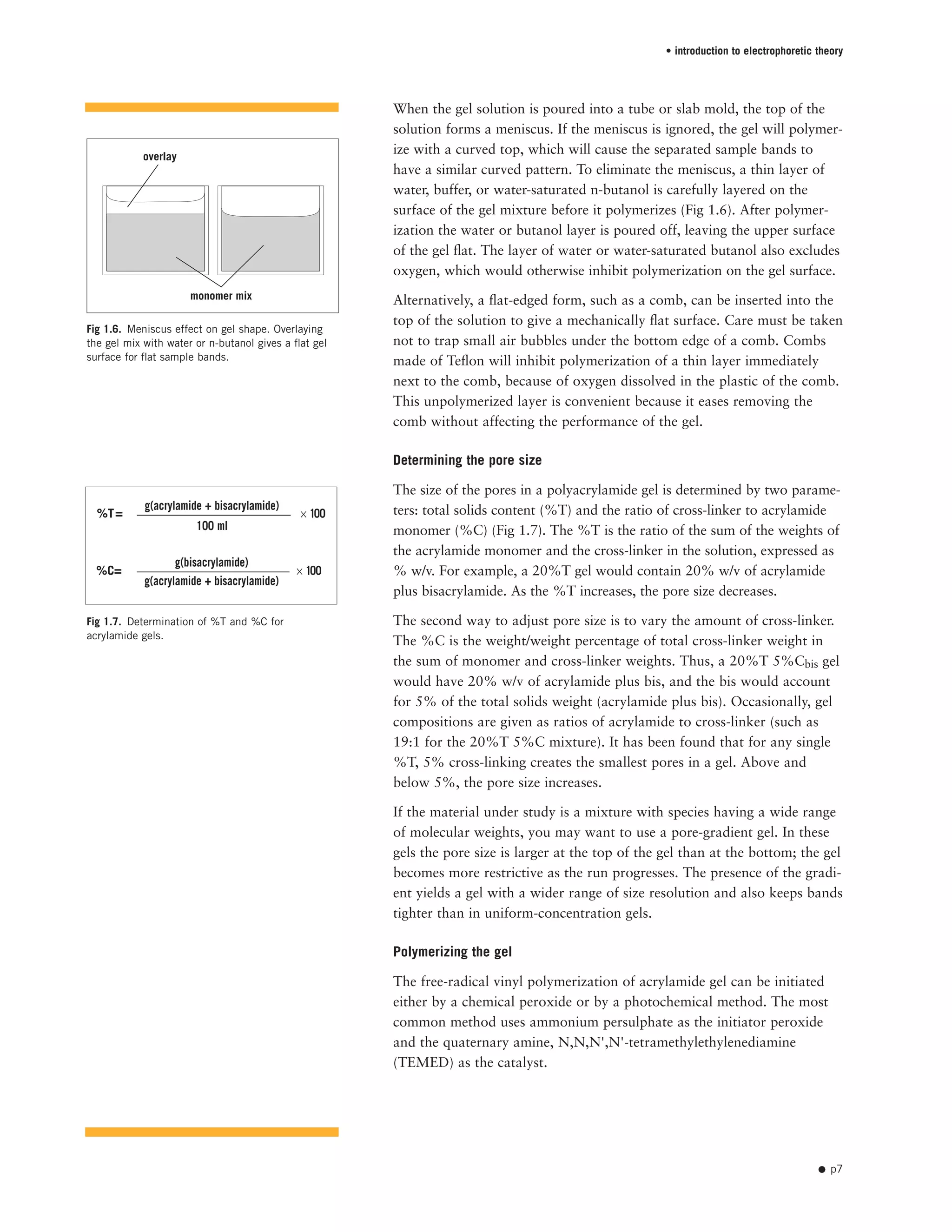
![3.2 Denaturing isoelectric focusing
In some cases it is advantageous to perform IEF in the presence of 8 M
urea. This denaturant renders some proteins more soluble under IEF
conditions, allowing the analysis of samples that cannot be separated
under native conditions.
The following protocol separates proteins under denaturing conditions in
a range from pH 3 to pH 10. A dried polyacrylamide gel (CleanGel IEF)
is rehydrated with the IEF solution before electrophoresis.
3.2.1 Solutions
Denaturing IEF rehydration solution Final concentration Amount
(8 M urea, 7.4% v/v Pharmalyte™
carrier ampholyte pH 3–10, 10.5 ml)
Urea (FW 60.06) 8 M 5.04 g
Pharmalyte 3–10 carrier ampholyte mixture 7.4% (v/v) 780 µl
ddH2O to 10.5 ml
If desired, a reducing agent (60 mM dithiothreitol [DTT]) and/or a detergent
(0.5% (w/v) Triton X-100 or CHAPS) may be added as well.
3.2.2 Materials and equipment
• Denaturing IEF rehydration solution, pH 3–10
• CleanGel IEF (dried polyacrylamide gel on plastic backing)
• Filter paper
• Gel Pool™ rehydration tray
• Rotary laboratory shaker
• Multiphor II Flatbed Electrophoresis Unit
• MultiTemp III Thermostatic Circulator
• IEF sample applicator strip
• IEF sample application pieces
• EPS 3501 XL high-voltage power supply
3.2.3 Procedure
Gel rehydration
1. Open the gel package and remove the dry gel.
The dry gel can be used in one piece or, depending on the number of
samples, cut into portions with scissors. Unused portions of gel can be
wrapped in plastic or placed in sealed plastic bags and stored at -20 °C
until use.
2. Select the appropriate-sized chamber of the rehydration tray. Clean the
rehydration tray with distilled or deionized water and dry with tissue
paper. Pipette the rehydration solution into the chamber. For a full-size
gel, use 10.4 ml. For portions of the gel, reduce the volume accordingly
(e.g. use 5.2 ml for half a gel).
The rehydration solution should include the components desired for the
separation: urea, carrier ampholytes, plus any detergents or reductants.
protein electrophoresis • isoelectric focusing of proteins
tm 80-6013-88 • p48
Fig 3.8. Example of isoelectric focusing using
CleanGel IEF.](https://image.slidesharecdn.com/manualeletroforese-160916131413/75/ICSA17-Imunologia-Manual-eletroforese-53-2048.jpg)


![Glossary
ammonium persulphate The initiator of acrylamide polymerization. Used
with TEMED to prepare polyacrylamide gels.
ampholyte The general term for amphoteric compounds (i.e. compounds
having both acidic and basic groups, H+ donor and acceptors, respec-
tively) used in isoelectric focusing. Ampholytes form a pH gradient by
migrating during electrophoresis to their isoelectric point in the gel. The
exact isoelectric point depends on the number and proportion of acidic
and basic groups and their pK’s. These titratable groups define the pH at
the isoelectric point by their buffering capacity. A variety of pH ranges
are available commercially.
anode The positive (+) electrode. Negatively charged proteins (anions)
move toward the anode. The anode is connected to the power supply
with the red high-voltage lead.
anolyte The electrode solution used in the positive (+) or anodic buffer
chamber in systems where two separate electrode buffers are used, such
as isoelectric focusing. Typically, phosphoric or acetic acid is used.
antigen A compound that, when injected into an animal, causes the
production of antibodies.
cathode The negative (–) electrode. Positively charged proteins (cations)
move toward the cathode. The cathode is connected to the power supply
with the black high-voltage lead.
catholyte The electrode solution used in the negative (–) or cathodic buffer
chamber in systems where two separate electrode buffers are used, such as
isoelectric focusing. Typically sodium hydroxide or histidine is used.
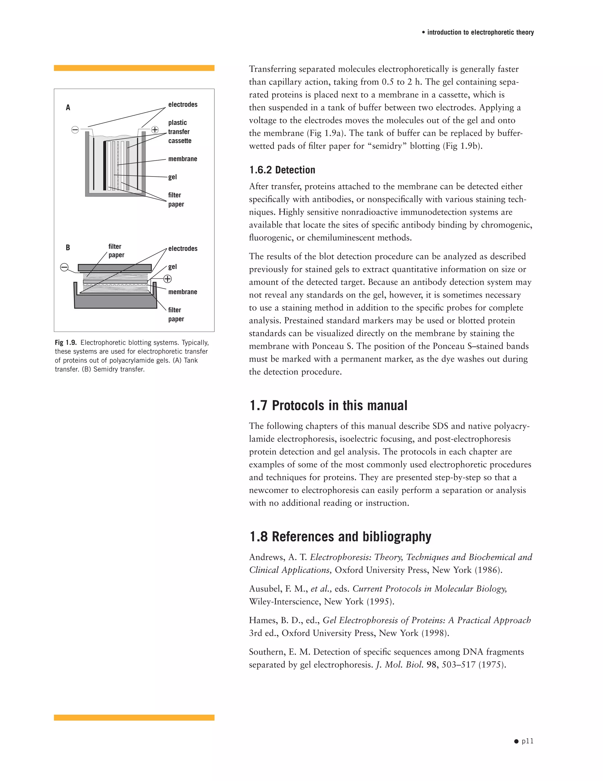
%C – The percentage of cross-linker in the polyacrylamide solution:
The amount of cross-linker (bisacrylamide) varies depending on the appli-
cation. The increased cross-linking gives a stronger gel, an important
consideration for low-percentage acrylamide gels.
CHAPS [3-(3-cholamidoproplyl[dimethylammonio])-1-propanesulphonate]
A zwitterionic detergent with the ability to disrupt nonspecific protein
interactions and preserve the native form of proteins. Used for protein
solubilization during sample preparation for IEF and 2-D electrophoresis.
Coomassie Brilliant Blue R250, R350, and G250 Protein stains used to
visualize proteins after electrophoresis.
discontinuous gel electrophoresis Gel electrophoresis with different stack-
ing and separating buffers to resolve macromolecules such as proteins.
Discontinuous electrophoresis provides superior resolution compared
with continuous (single-buffer) systems.
• glossary
• p67
g(bisacrylamide)
g(acrylamide + bisacrylamide)
%C = × 100](https://image.slidesharecdn.com/manualeletroforese-160916131413/75/ICSA17-Imunologia-Manual-eletroforese-72-2048.jpg)


This technical manual provides guidance on protein electrophoresis techniques. It begins with an introduction to electrophoretic theory, including electrical parameters, buffers, heat effects, matrix materials, analysis, and blotting. Subsequent chapters cover polyacrylamide gel electrophoresis, isoelectric focusing, and gel analysis methods. Safety considerations are discussed for chemical and electrical hazards. The manual aims to be both a teaching guide and reference for experienced and new users of protein electrophoresis.


