1. RCP3 ROBO Cylinder
RCP3-TA3C ROBO Cylinder Mini Table Type Motor Unit Coupled 36mm Width Pulse Motor Ball Screw
6 : 6mm See Options below
4 : 4mm
2 : 2mm
(1) The load capacity is based on operation at an acceleration of 0.3G (0.2G for the 2mm-lead
model, or when used vertically).
0.3G (0.2G for 2mm lead) is the upper limit of the acceleration.
O I N
P1: PCON
RPCON
PSEL
P3: PMEC
PSEP
■ Lead and Load Capacity (Note 1) Please note that the maximum load capacity decreases as the speed increases. ■ Stroke and Maximum Speed
Feed
Screw Horizontal (kg) Vertical (kg)
2
1.75
1.5
1.25
1.0
0.75
0.5
0.25
1.6
1.4
1.2
1.0
0.8
0.6
0.4
0.2
(Note 2) See page A-66 for pushing force graphs.
Ball Screw
Lead
(mm)
Max. Load Capacity (Note 1) Positioning
Repeatability
(mm)
Maximum
Push Force (N)
(Note 2)
Actuator Specifications
Model
Stroke
(mm)
RCP3-TA3C-I-20P-6- 1 - 2 - 3 - 4
RCP3-TA3C-I-20P-4- 1 - 2 - 3 - 4
RCP3-TA3C-I-20P-2- 1 - 2 - 3 - 4
Ball
Screw
6 ~ 0.7
4 ~ 1.4
2 ~ 2
~ 0.3
~ 0.6
~ 1
9
14
28
20~100
(10mm
increments)
±0.02
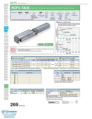
■ Speed vs. Load Capacity
Due to the characteristics of the Pulse motor, the RCP3 series'
load capacity decreases at high speeds. In the table below, check
if your desired speed and load capacity are supported.
0 50 100 150 200 250 300 350
Speed (mm/s)
0
Horizontal
2mm lead
4mm lead
6mm lead
11..44
0.7
Load Capacity (kg)
0 50 100 150 200 250 300 350
Speed (mm/s)
0
Vertical
00..33
0.7
Load Capacity (kg)
2mm lead
4mm lead
6mm lead
Legend 1 Stroke 2 Compatible controller 3 Cable length 4 Options
1 Stroke List 3 Cable List
4 Option List
Stroke
Lead
20 ~ 100
(mm)
300 <200>
200 <133>
100 <67>
6
4
2
(Unit: mm/s)
* See page Pre-35 for an explanation of the naming convention.
20P: Pulse motor
20 □ size
I: Incremental
* The simple
absolute encoder
is also considered
type "I".
N : None
P : 1m
S : 3m
M : 5m
X □□ : Custom
■ Configuration: RCP3 TA3C I 20P
Series Type Encoder Motor Lead Stroke Compatible Controllers Cable Length Option
Type Cable Symbol Standard Price
Standard
(Robot Cables)
Special Lengths
P (1m)
S (3m)
M (5m)
X06 (6m) ~ X10 (10m)
X11 (11m) ~ X15 (15m)
X16 (16m) ~ X20 (20m)
–
–
–
–
–
–
-
-
-
-
-
-
-
-
-
20
30
40
50
60
70
80
90
100
Name Option Code See Page Standard Price
B
NM
→ A-25
→ A-33
Brake
Reversed-home
–
–
P
T
Notes on
Selection
* The values enclosed in "< >" apply to vertical usage.
* The RCP3 comes standard with a robot cable.
* See page A-39 for cables for maintenance.
Actuator Specifications
Item Description
Drive System
Lost Motion
Base
Allowable Dynamic Moment (Note 3)
Ambient Operating Temp./Humidity
(Note 3) Based on a 5,000km service life.
Ball screw ø6mm C10 grade
0.1mm or less
Material: Aluminum (white alumite treated)
Ma: 3.2 N∙m Mb: 4.6 N∙m Mc: 5.1 N∙m
0~40°C, 85% RH or less (non-condensing)
20: 20mm
〜
100: 100mm
(10mm pitch
increments)
P. A-5 Technical
References
Stroke (mm) Standard Price
Directions of Allowable Load Moments
Ma Mb Mc
269 RCP3-TA3C
Slider
Type
Mini
Standard
Controllers
Integrated
Rod
Type
Mini
Standard
Controllers
Integrated
Table/Arm
/Flat Type
Mini
Standard
Gripper/
Rotary Type
Linear Servo
Type
Cleanroom
Type
Splash Proof
Controllers
PMEC
/AMEC
PSEP
/ASEP
ROBO
NET
ERC2
PCON
ACON
SCON
PSEL
ASEL
SSEL
XSEL
Pulse Motor
Servo Motor
(24V)
Servo Motor
(200V)
Linear
Servo Motor
Sold & Serviced By:
ELECTROMATE
Toll Free Phone (877) SERVO98
Toll Free Fax (877) SERV099
www.electromate.com
sales@electromate.com
2. Moment offset
reference position
10.5
28.5
Dimensions
3-M4
depth 6 24
5
10
33
36
41
24
4.5
16
ø3H7 depth 3.5
(from top of table)
12 G×40 H-M3 depth 5
RCP3 ROBO Cylinder
Motor-encoder
cable connector*1
3H7 depth 3.5
(from top of table)
40
(between reamer hole
and oblong hole)
4
38
If equipped with a brake
added to the A section. ( )
32
29
5
7.4
3
7.5
(Motor section height)
3.5
30
18
L Secure at least 100
102.5
26
23
Home ME*2
8
ST
3
ME SE
12 18.5
ST : Stroke
30.6 (Connector width)
A
B
C
D
3H7 depth 3.5
(from bottom
of base)
4
50
(between reamer and
J-M3 oblong holes)
depth 5
28
ø3H7 depth 3.5
(from bottom of base) 5 E×50 F 7.5
* The above brake unit will be
A
ME : Mechanical end
SE : Stroke end
*1 The motor-encoder cable is connected directly to the motor cover of the actuator.
See page A-39 for details on cables.
*2 When homing, the slider moves to the mechanical end; therefore, please watch for
any interference with the surrounding objects.
■ Dimensions/Weight by Stroke
Stroke
L
No Brake
Brake-equipped
A
B
C
D
E
F
G
H
J
Weight (kg)
* Adding a brake will increase the actuator's weight by 0.1kg.
20 30 40 50 60 70 80 90 100
224
262
87.5
95.5
121.5
91
1
28.5
1
4
6
0.5
234
272
97.5
105.5
131.5
101
1
38.5
1
4
6
0.5
244
282
107.5
115.5
141.5
111
1
48.5
1
4
6
0.5
254
292
117.5
125.5
151.5
121
1
58.5
1
4
6
0.6
264
302
127.5
135.5
161.5
131
2
18.5
2
6
8
0.6
274
312
137.5
145.5
171.5
141
2
28.5
2
6
8
0.6
284
322
147.5
155.5
181.5
151
2
38.5
2
6
8
0.6
294
332
157.5
165.5
191.5
161
2
48.5
2
6
8
0.7
304
342
167.5
175.5
201.5
171
2
58.5
2
6
8
0.7
For Special Orders P. A-9
2 Compatible Controllers
The RCP3 series actuators can operate with the controllers below. Select the controller according to your usage.
Name External View Model Description Max. Positioning Points Input Voltage Power Supply Capacity Standard Price See Page
Solenoid Valve Type
PMEC–C–20PI–NP–2–1 Easy–to–use controller, even for beginners
3 points
AC100V
AC200V
See P481 – → P477
PSEP–C–20PI–NP–2–0
Operable with same signal as solenoid valve.
Supports both single and double solenoid types.
No homing necessary with simple absolute type.
DC24V 2A max.
–
→ P487
Splash–Proof
Solenoid Valve Type
PSEP–CW–20PI–NP–2–0 –
Positioner Type PCON–C–20PI–NP–2–0
Positioning is possible for up to 512 points 512 points
–
→ P525
Safety–Compliant
Positioner Type
PCON–CG–20PI–NP–2–0 –
Pulse Train Input Type
(Differential Line Driver)
PCON–PL–20PI–NP–2–0
Pulse train input type with
differential line driver support
(−)
–
Pulse Train Input Type
(Open Collector)
PCON–PO–20PI–NP–2–0
Pulse train input type with
open collector support
–
Serial
Communication Type
PCON–SE–20PI–N–0–0 Dedicated to serial communication 64 points –
Field Network Type RPCON–20P Dedicated to field network 768 points – → P503
Program Control
Type
PSEL–C–1–20PI–NP–2–0
Programmed operation is possible
Operation is possible on up to 2 axes
1500 points – → P557
* This is for the single-axis PSEL.
* 1 is a placeholder for the power supply voltage (1: 100V, 2: 100~240V).
RCP3-TA3C 270
Slider
Type
Mini
Standard
Controllers
Integrated
Rod
Type
Mini
Standard
Controllers
Integrated
Table/Arm
/Flat Type
Mini
Standard
Gripper/
Rotary Type
Linear Servo
Type
Cleanroom
Type
Splash Proof
Controllers
PMEC
/AMEC
PSEP
/ASEP
ROBO
NET
ERC2
PCON
ACON
SCON
PSEL
ASEL
SSEL
XSEL
Pulse Motor
Servo Motor
(24V)
Servo Motor
(200V)
Linear
Servo Motor
Sold & Serviced By:
ELECTROMATE
Toll Free Phone (877) SERVO98
Toll Free Fax (877) SERV099
www.electromate.com
sales@electromate.com