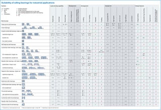
1. Suitability of rolling bearings for industrial applications
Symbols
+++ excellent ↔ double direction
++ good ← single direction
+ fair ◻ non-locating displacement on the seat
- poor ◾ non-locating displacement within the bearing
– – unsuitable ✓ yes
✗ no
Bearing type
Load carrying capability Misalignment Arrangement Suitable for Design features
Radial load
Axial load
Moment load
Static misalignment
Dynamic misalignment
(few tenths of a degree)
Locating
Non-locating
Adjusted
Floating
Long grease life
High speed
Low run-out
High stiffness
Low friction
Integral sealing
Separable ring mounting
Tapered bore
Standard housings and
accessories available
Deep groove ball bearings + + ↔ A –, B + – – – ↔ ◻ ✗ ✓
A +++
B ++
A +++
B +
A +++
B ++
+ +++ A ✓ ✗ ✗ ✗
Insert bearings + + ↔ – – ++ – – ↔ ↔ ✗ ✗ +++ ++
A, B +
C ++
+ ++ ✓ ✗ ✗ ✓
Angular contact ball bearings, single row +1) ++ ← – – – – – ✗ ✗ ✓ ✗ ++ ++ +++ ++ ++ ✓ ✗ ✗ ✗
matched single row
A, B ++
C ++1)
A, B ++ ↔
C ++ ←
A ++, B +
C – –
A, C – –,
B –
– –
A, B ↔
C ←
A, B ◻
C ✗
✗ ✗ ++ ++ +++ ++ ++ ✗ ✗ ✗ ✗
double row ++ ++ ↔ ++ – – – – ←→ ◻ ✗ ✗ ++ ++ ++ ++ ++ A ✓ B ✓ ✗ ✗
four-point contact +1) ++ ↔ – – – – – – ↔1) – – – – – – + +++ ++ ++ ++ ✗ ✓ ✗ ✗
Self-aligning ball bearings + – – – +++ +2) ↔ ◻ ✗ ✓ +++ ++ ++ + +++ ✓ ✗ ✓ ✓
Cylindrical roller bearings, with cage ++ – – – – – – – ✗ ◾ ✗ ✗ ++ +++ +++ ++ +++ ✗ ✓ ✗ ✗
++
A, B + ←
C, D + ↔
– – – – –
A, B ←
C, D ↔
A, B ◾ ←
C, D ✗
✗
A ✓
B, C, D ✗
++3) +++ ++ ++ +++ ✗ ✓ ✗ ✗
full complement, single row +++ + ← – – – – – ← A, B ← ✗ ✓ – + + +++ – ✗
A ✗
B ✓
✗ ✗
full complement, double row +++
A– –, B +
← C + ↔
– – – – –
B ←
C, D ↔
A ◾ ↔
B ◾ ←
✗ ✗ – + + +++ – D ✓ ✗ ✗ ✗
Needle roller bearings, with steel rings ++ – – – –
A, B –
C ++
– – ✗ ◾ ←→ ✗ ✗ ++ ++ + ++ + A ✓ ✓ ✗ ✗
assemblies / drawn cups ++
A, B – –
C –
– – – – –
A, B ✗
C ←
A, B ◾
C ◾ ←
✗ ✗ ++ ++ + ++ + B, C ✓ ✓ ✗ ✗
combined bearings ++
A –, B +
C ++
– – – – – – ← ✗ ✓ ✗ + + + ++ + ✗ ✓ ✗ ✗
Tapered roller bearings, single row +++1) ++ ← – – – – – ← ✗ ✓ ✗ + ++ +++ ++ + ✗ ✓ ✗ ✗
matched single row
A, B +++
C +++1)
A, B ++ ↔
C ++ ←
A +, B ++
C – –
A –
B, C – –
– –
A, B ↔
C ←
A, B ◻
C ✗
A, B ✗
C ✓
✗ + + ++ +++ + ✗ ✓ ✗ ✗
double row +++ ++ ↔
A +
B ++
A –, B – – – – ←→ ◻ ✗ ✗ + + ++ +++ + ✓ ✓ B ✓ ✗
Spherical roller bearings +++ + ↔ – – +++ +2) ←→ ◻ ✗ ✓ + ++ +++ ++ + ✓ ✗ ✓ ✓
CARB toroidal roller bearings, with cage +++ – – – ++ – ✗ ◾ ✗ ✗ + ++ +++ ++ + ✗ ✗ ✓ ✓
full complement +++ – – – ++ – ✗ ◾ ✗ ✗ – + +++ ++ – ✓ ✗ ✓ ✓
Thrust ball bearings – –
A + ←
B + ↔
– – – – – –
A ←
B ↔
✗ ✗ ✗ + – ++ + + ✗ ✓ ✗ ✗
with sphered housing washer – –
A + ←
B + ↔
– – ++ – –
A ←
B ↔
✗ ✗ ✗ + – + + + ✗ ✓ ✗ ✗
Cylindrical roller thrust bearings – – ++ ← – – – – – – ← ✗ ✗ ✗ – – + +++ + ✗ ✓ ✗ ✗
Needle roller thrust beairngs – – ++ ← – – – – – – ← ✗ ✗ ✗ – – + +++ + ✗ ✓ ✗ ✗
Spherical roller thrust bearings +1) +++ ← – – +++ +2) ← ✗ ✓ ✗ – + + +++ + ✗ ✓ ✗ ✗
1) Provided the Fa/Fr ratio requirement is met 2) Reduced misalignment angle – contact SKF 3) Depending on cage and axial load level
A
A
A
A
A
A
A
A
A
A
A
A
A
A
B
B
B
B
B
B
B
B
B
B
B
B
C
C
C
C
C
D
C
C
D
A
B
B
B
C