This document provides information about Canada Mortgage and Housing Corporation (CMHC), which has been Canada's national housing agency for over 65 years. CMHC helps ensure the Canadian housing system remains one of the best in the world by providing a wide choice of quality, sustainable and affordable housing options. The document includes contact information for CMHC and notes that this publication is also available in French.


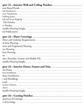
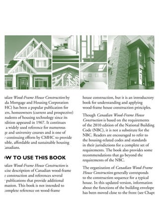
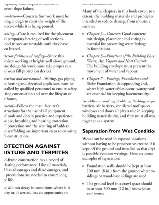

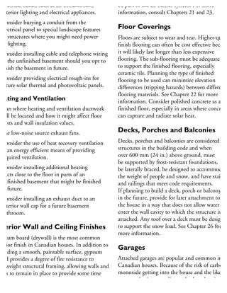
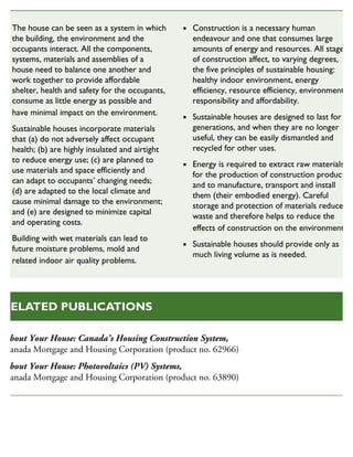
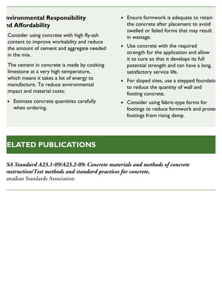
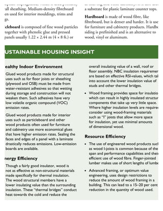
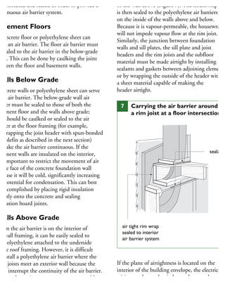
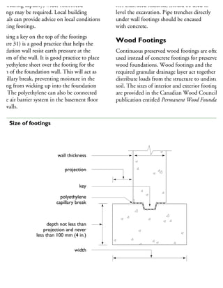
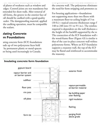
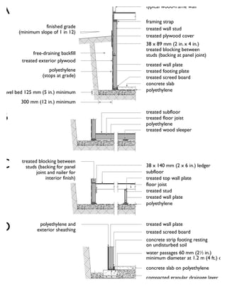
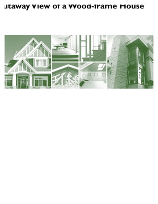
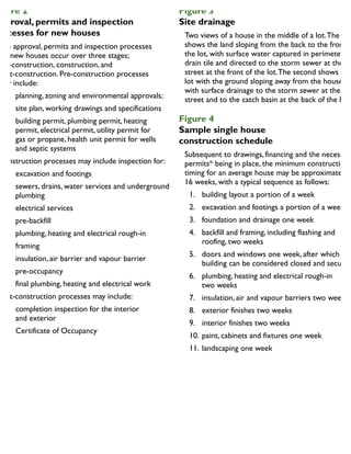
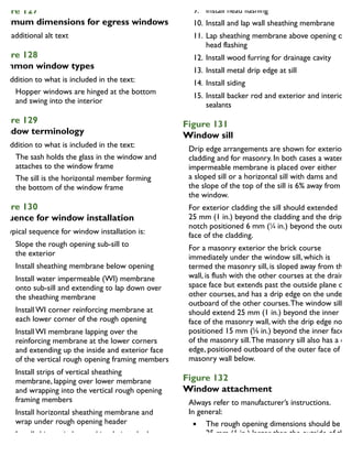
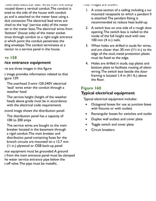
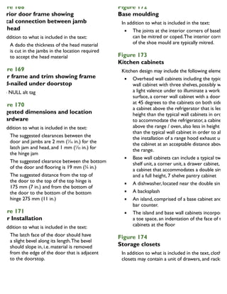
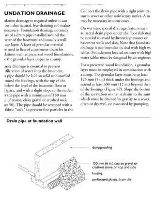
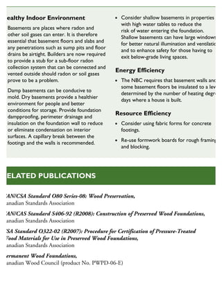
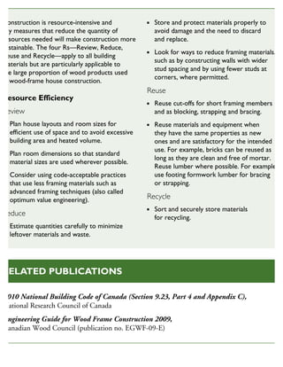
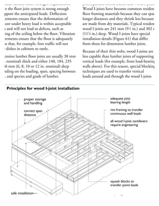
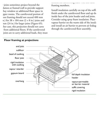
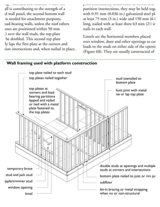
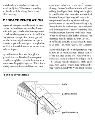
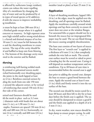
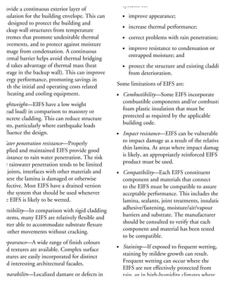
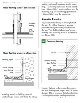
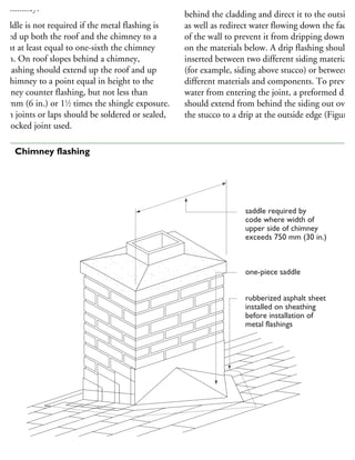
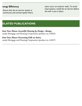
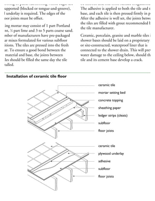
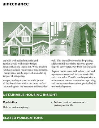
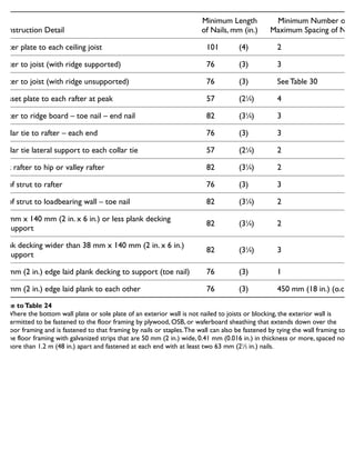
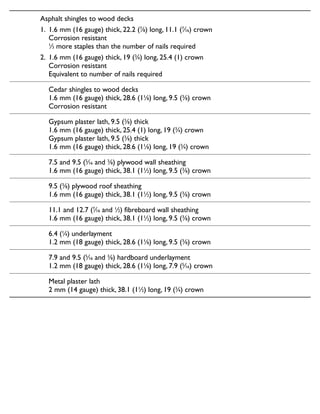
![hysical or ultraviolet damage with parging or
board finish. To resist cracking, reinforce the
ab with 9.5 mm (3
⁄8 in.) thick steel reinforcing
ars spaced 600 mm (24 in.) on centre in both
rections. (The steel bars have a metric product
esignation of 10M.) Alternatively, welded wire
esh can be used that forms a grid of 152 mm
6 in.) squares in which the thickness of the
eel is 3.4 mm (0.15 in.). [The metric product
esignation of this grid is 152 × 152 mm
MW 9.1 × 9.1.)]
mechanical float finish provides a smooth
nished surface.
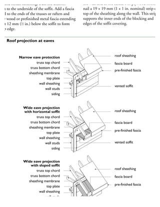
he requirements for footings and foundations
r houses with slabs-on-ground are similar to
hose for crawl spaces and constructed in the
me manner. A structural slab, which supports
ads from vehicles or the walls above, must be
esigned by an engineer.
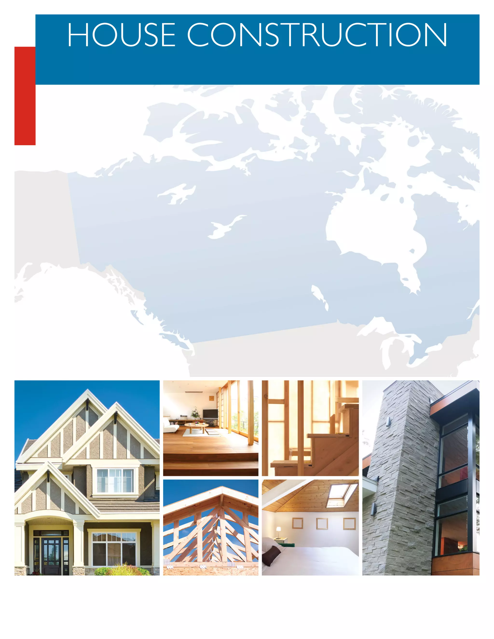
OUNDATION
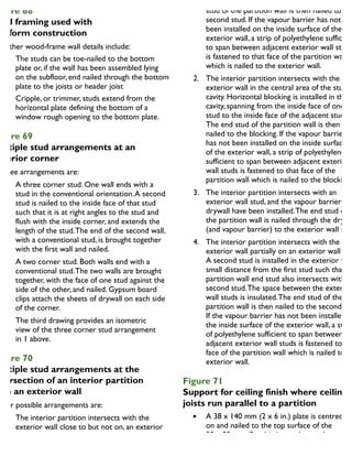
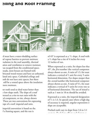
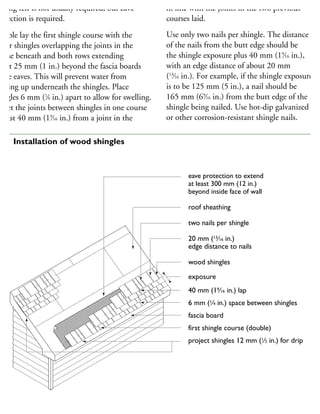
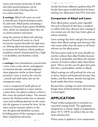
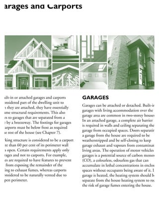
DAMPPROOFING
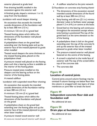
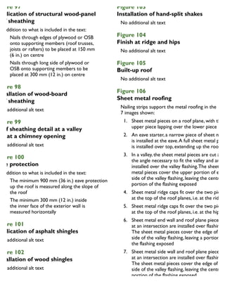
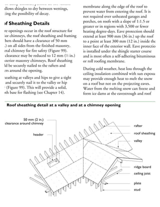
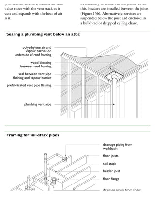
ampproofing is necessary for all
undations that contain habitable space to
strict the movement of soil moisture into
he wall. Dampproofing materials include
tumen, polyethylene or other sheet material.
n poorly-drained soils or soils with a high water
ble, waterproofing will be required.
ampproof concrete and unit masonry walls
elow grade with a heavy coat of bituminous
aterial applied on the exterior surface from the
otings to the finished grade line. Such a coating
usually sufficient to make the wall resistant
surface water moving down to the footing
rainage system. Mineral fibre insulation or
rainage layers are recommended to drain water
way from the foundation walls.
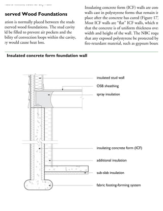
used must be compatible with the foam
formwork/insulation.
When backfilling walls, avoid causing damage to
the dampproofing, waterproofing, insulation or
drainage layer.
Dampproofing is also required on the interior o
concrete or unit masonry walls that come into
contact with interior wood framing supporting
insulation or interior finishes. When installed
between the foundation wall and interior framin
the dampproofing prevents moisture in the
foundation wall from coming into contact with
the wood framing. It usually consists of building
paper applied on the inside of the wall, and mus
extend from the basement floor and terminate a
the exterior finish grade level.
WATERPROOFING
Waterproofing is needed where there is a
likelihood of hydrostatic water pressure and
requires the services of a qualified professional
to identify which measures are to be taken to
deal with the water and the forces imposed on
the foundation. Waterproofed foundations need
not be dampproofed. For walls, waterproofing
consists of an impermeable membrane, such as
two layers of bitumen-saturated felt. The layers
of felt are attached to the wall and each other
and covered with liquid bitumen. Waterproofin
materials for ICF foundations must be compatib
with the foam formwork/insulation.
Floor slabs must also be waterproofed
where hydrostatic pressure could be an issue.
The waterproofing materials must consist of a
membrane sandwiched between two layers of
concrete, each layer not less than 75 mm
(3 in.) thick. The floor membrane must be
sealed to the wall membrane. In many cases,](https://image.slidesharecdn.com/houseframingguidelines-150921192010-lva1-app6891/85/House-framing-guidelines-108-320.jpg)
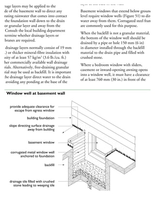
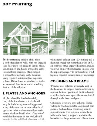
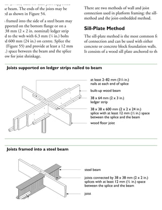
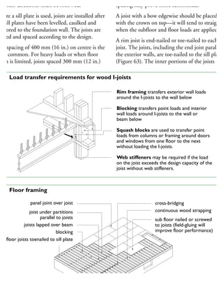


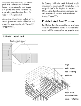
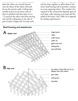
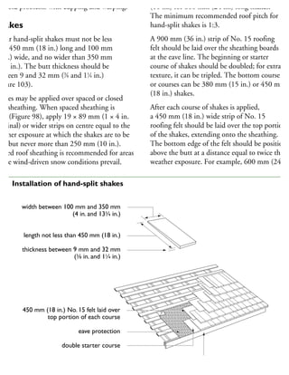
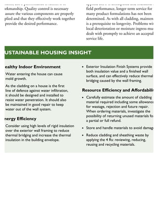
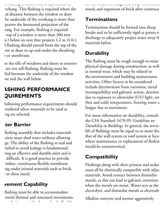
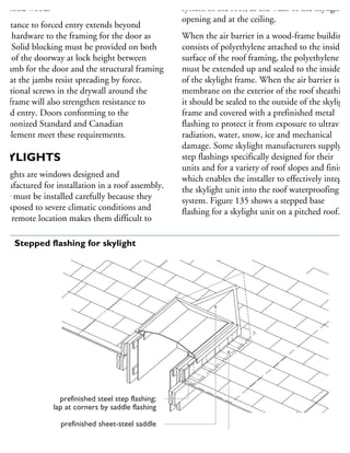
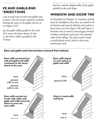


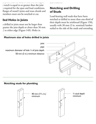
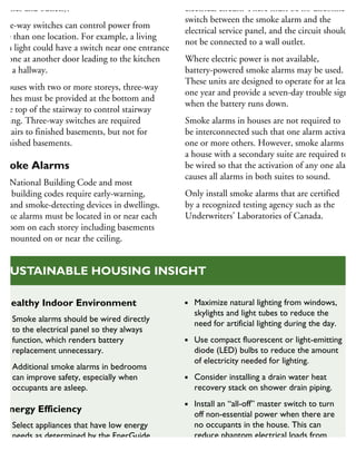
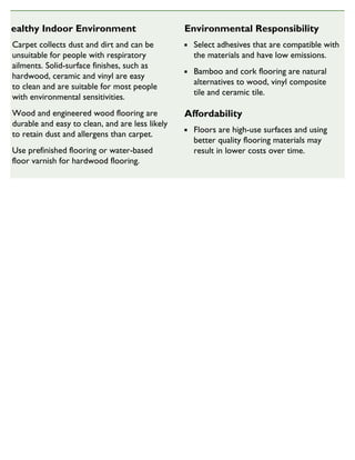
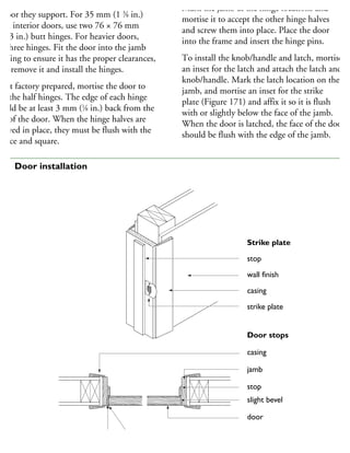
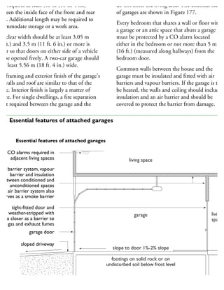

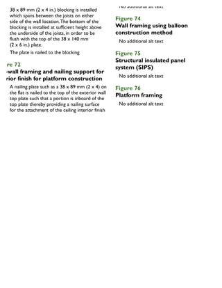
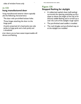
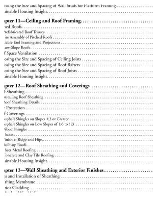
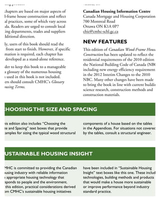
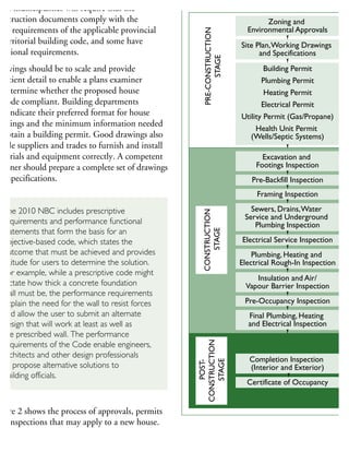
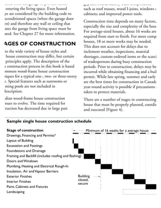
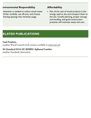
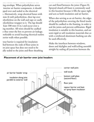
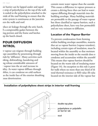
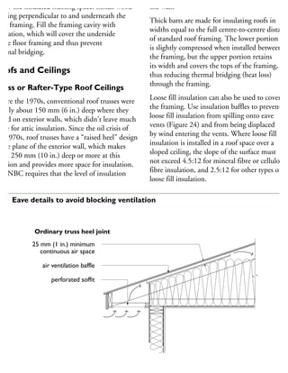
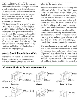
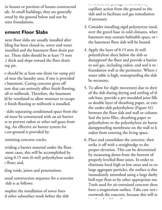
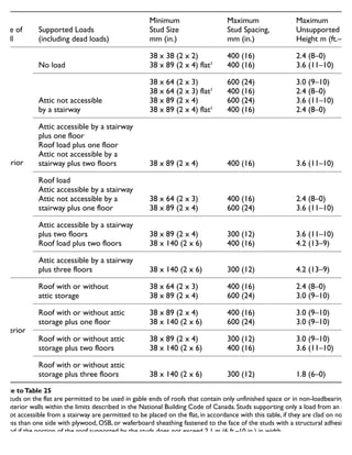
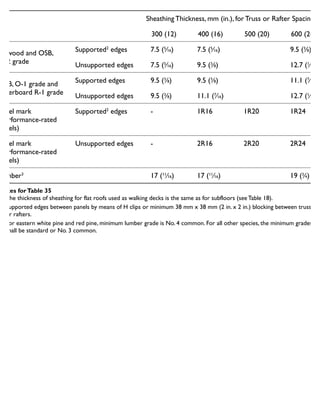
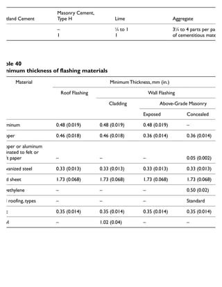
![Tables
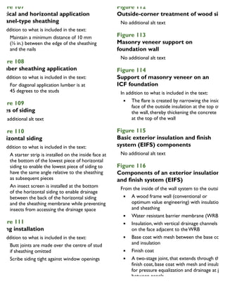
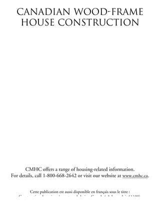
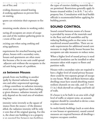
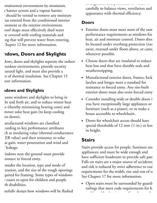
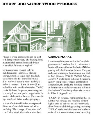
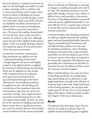
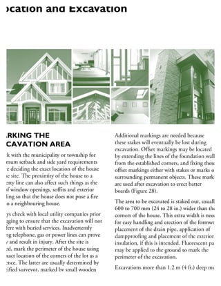
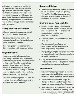
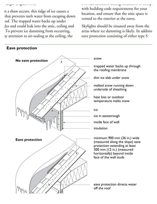
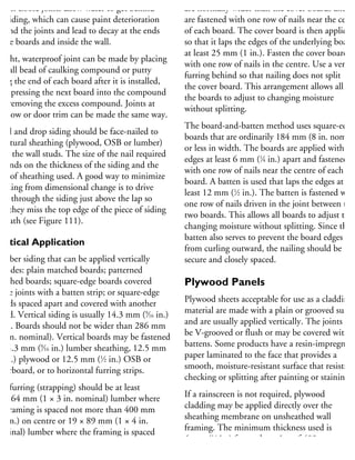
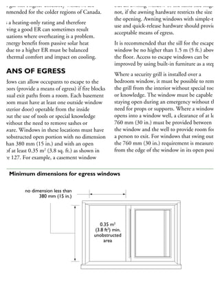
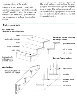
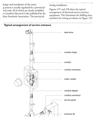
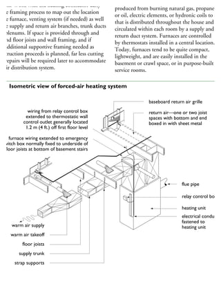
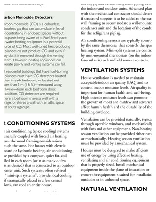
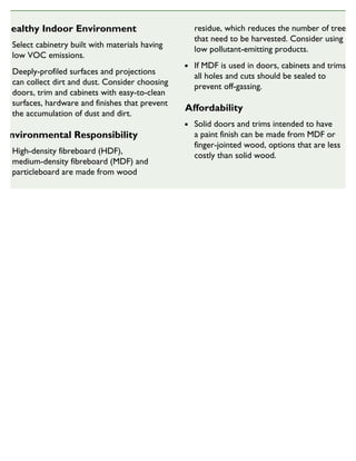
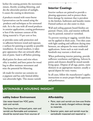
LIST OF TABLES
Table 1 Conversion factors. . . . . . . . . . . . . . . . . . . . . . . . . . . . . . . . . . . . . . . . . . . . . . . . 26
Table 2 Concrete mixes (by volume) . . . . . . . . . . . . . . . . . . . . . . . . . . . . . . . . . . . . . . . . 26
Table 3 Minimum depths of foundations. . . . . . . . . . . . . . . . . . . . . . . . . . . . . . . . . . . . . 26
Table 4 Minimum footing sizes (Length of supported joists 4.9 m [16 ft.] or less)
(Design floor load 2.4 kN/m2
[50 lb./ft.2
] maximum) . . . . . . . . . . . . . . . . . . . . . 26
Table 5 Minimum thickness of foundation walls . . . . . . . . . . . . . . . . . . . . . . . . . . . . . . . 26
Table 6 Mortar mix proportions (by volume) . . . . . . . . . . . . . . . . . . . . . . . . . . . . . . . . . . 26
Table 7 Dimension lumber – grades and uses. . . . . . . . . . . . . . . . . . . . . . . . . . . . . . . . . . 26
Table 8 Sizes for dimension lumber and boards . . . . . . . . . . . . . . . . . . . . . . . . . . . . . . . . 26
Table 9 Facsimiles of lumber grade marks approved for use in Canada . . . . . . . . . . . . . . . 27
Table 10 Commercial species of lumber . . . . . . . . . . . . . . . . . . . . . . . . . . . . . . . . . . . . . . . 27
Table 11 Effective thermal resistance of assemblies in buildings with a
heat-recovery ventilator . . . . . . . . . . . . . . . . . . . . . . . . . . . . . . . . . . . . . . . . . . . . 27
Table 12 Effective thermal resistance of assemblies in buildings without a heat
recovery ventilator . . . . . . . . . . . . . . . . . . . . . . . . . . . . . . . . . . . . . . . . . . . . . . . . 27
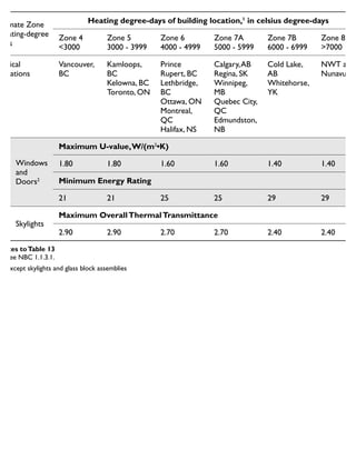
Table 13 Required thermal characteristics of windows, doors and skylights . . . . . . . . . . . . 27
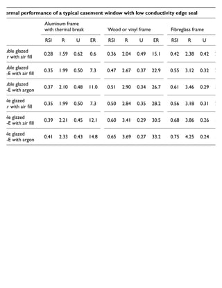
Table 14 Comparison of typical window thermal efficiencies . . . . . . . . . . . . . . . . . . . . . . . 27
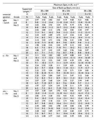
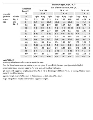
Table 15 Maximum spans for built-up floor beams supporting not more than one floor . . 27](https://image.slidesharecdn.com/houseframingguidelines-150921192010-lva1-app6891/85/House-framing-guidelines-287-320.jpg)
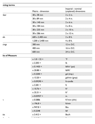
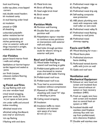
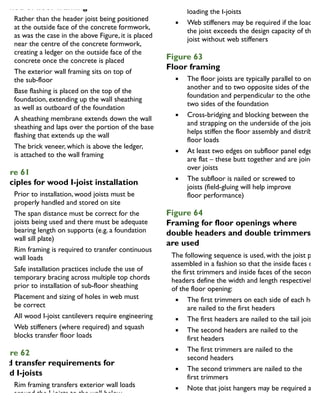
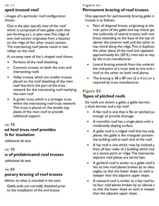
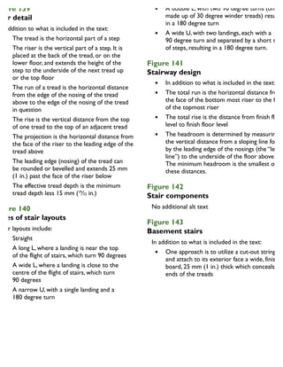
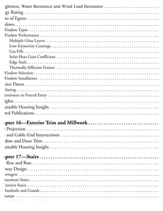
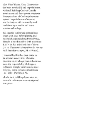
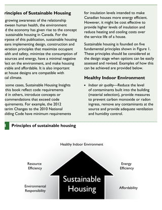
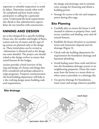
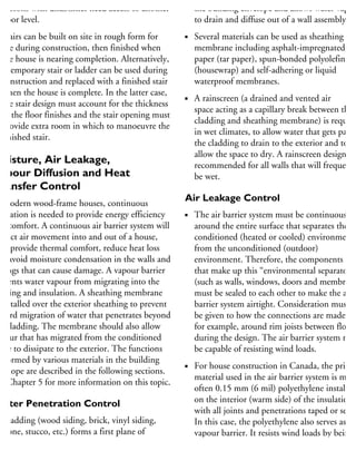
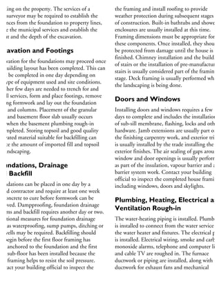
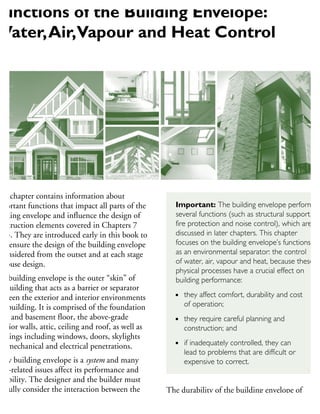
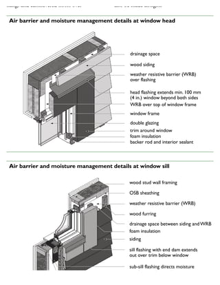
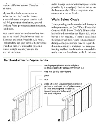
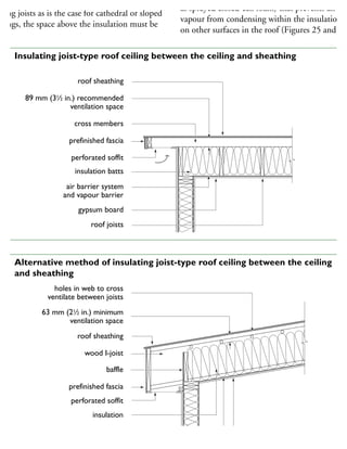
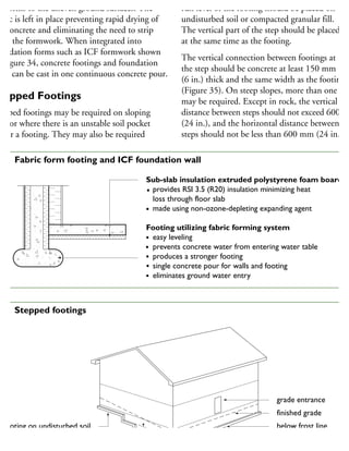
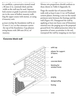
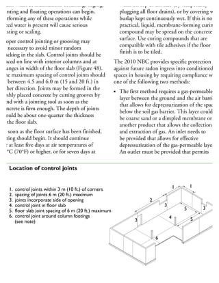
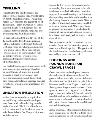
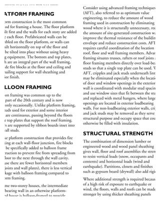
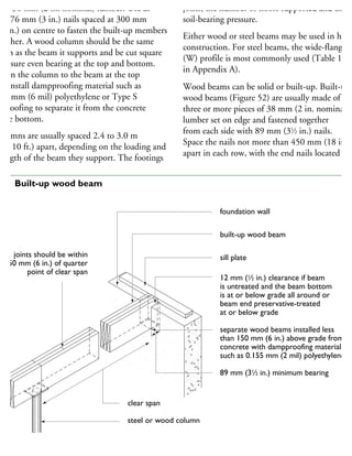
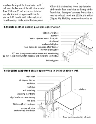
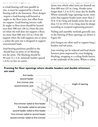
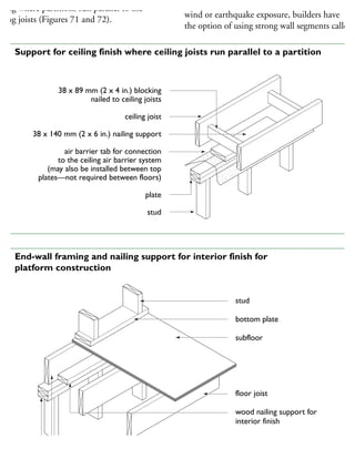
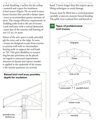
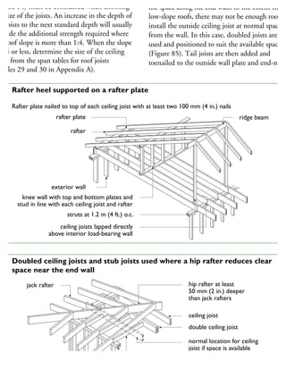
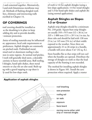
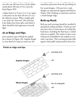
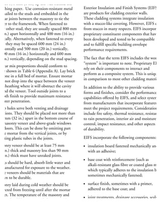
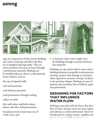
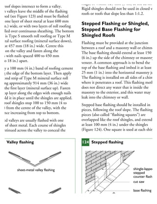
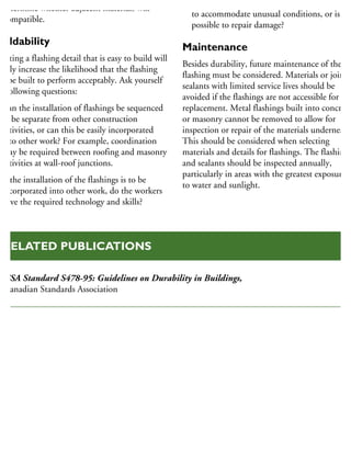
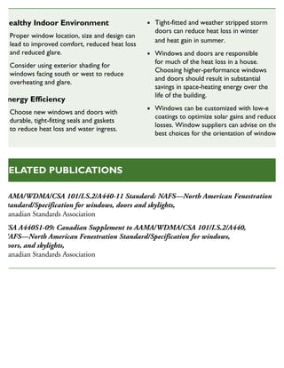
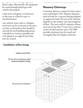
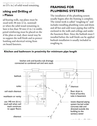
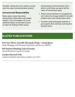
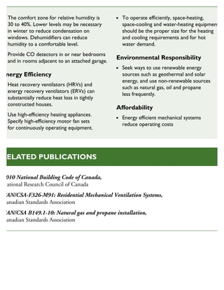
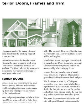
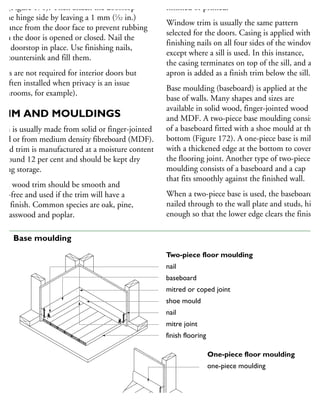
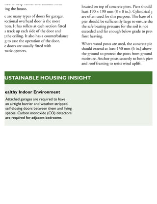
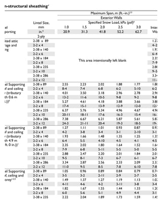
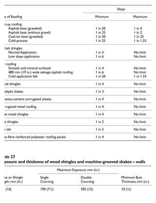
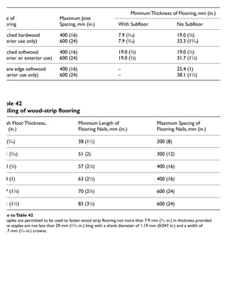
![No. of Floors
Supported
Minimum Widths of Strip Footings, mm (in.)
Minimum Area of
Column Footings1
,
m2
(sq. ft.)
Supporting
Exterior Walls
Supporting
Interior Walls
1 250 (10)2
200 (8)3
0.4 (4.3)
2 350 (14)2
350 (14)3
0.75 (8)
3 450 (18)2
500 (20)3
1.0 (11)
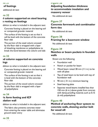
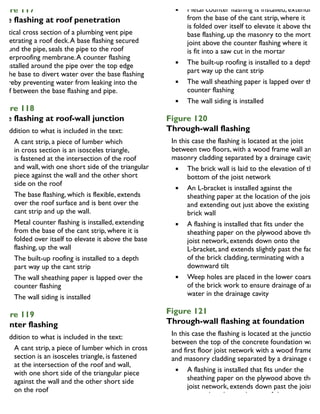
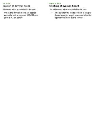
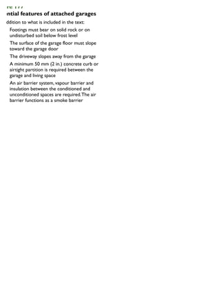
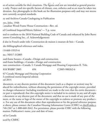
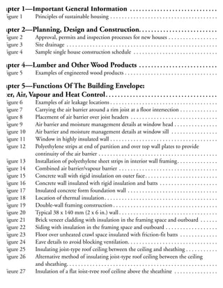
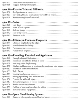
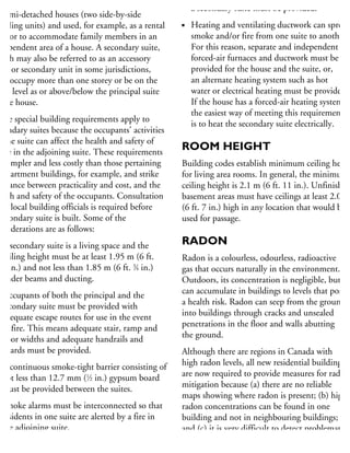
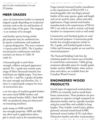
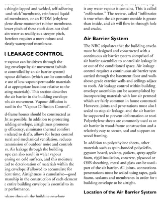
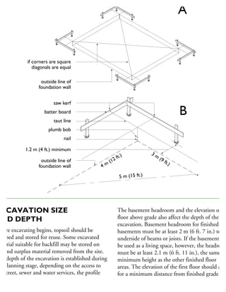
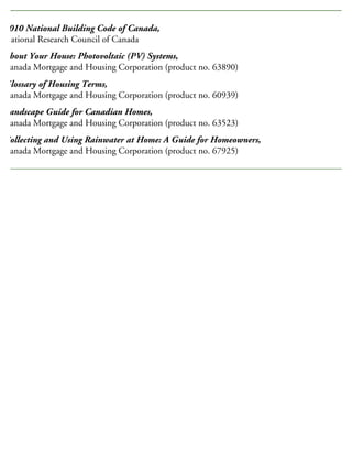
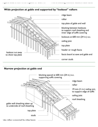
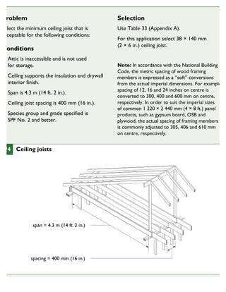
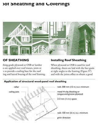
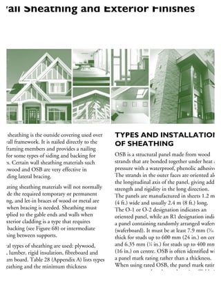
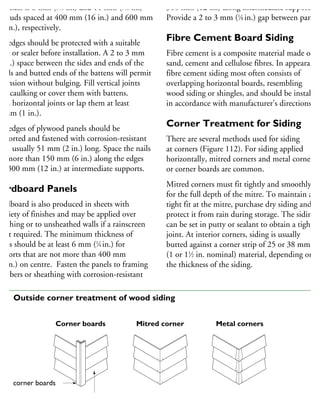
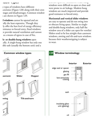
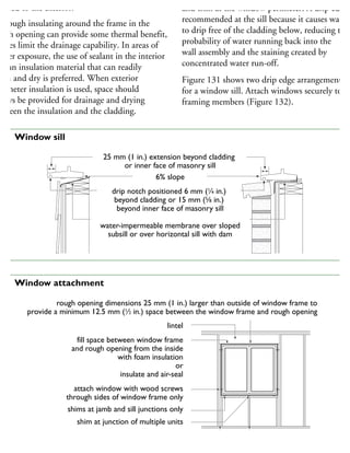
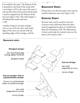
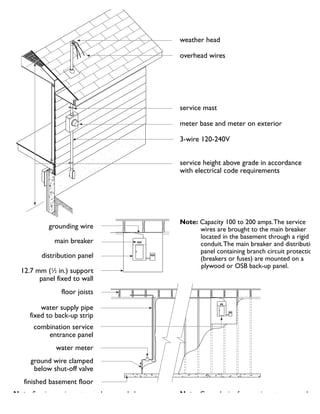
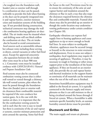
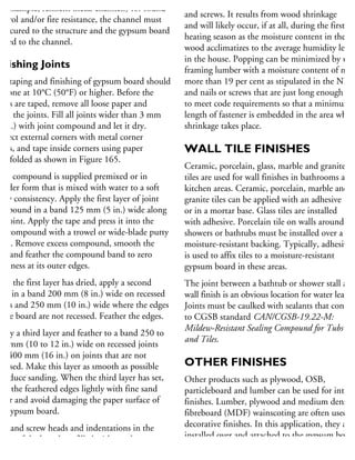
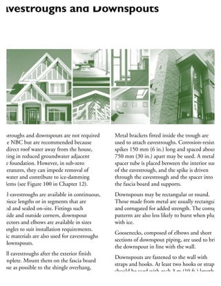
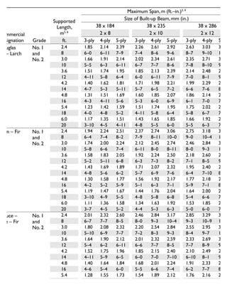
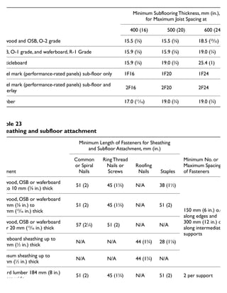
Notes toTable 4
1. Sizes are based on columns spaced 3 m (9 ft., 10 in.) (on centre). For other column spacings, footing areas must be adjusted
in proportion to the distance between columns.
2. For each storey of masonry veneer over wood-frame construction, footing widths must be increased by 65 mm (21
⁄2 in.).
For each storey of masonry construction other than foundation walls, the footing width must be increased by 130 mm (51
⁄8 in.)
3. For each storey of masonry supported by the footing, the footing width must be increased by 100 mm (4 in.).
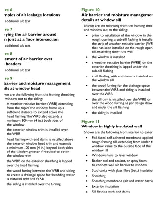
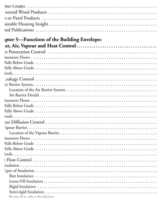
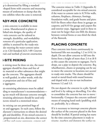
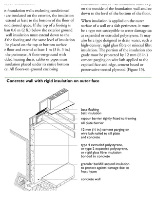
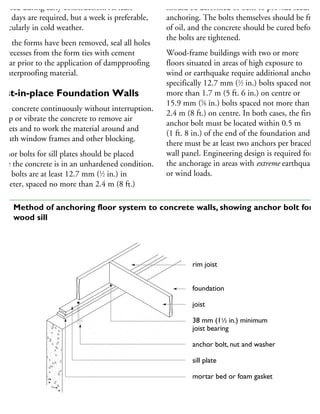
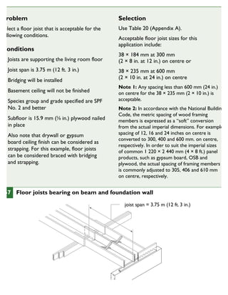
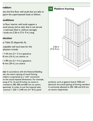
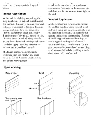
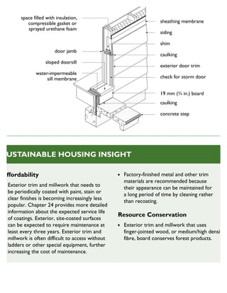
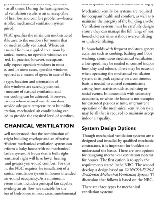
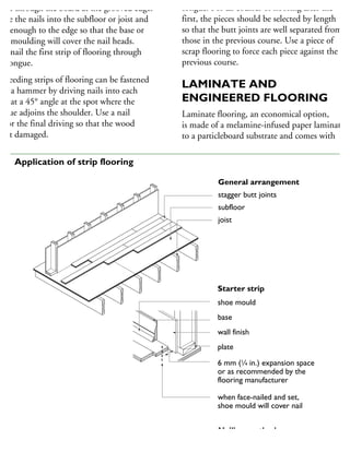
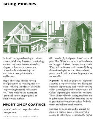
Minimum footing sizes (Length of supported joists 4.9 m [16 ft.] or less)
(Design floor load 2.4 kN/m2
[50 lb./ft.2
] maximum)
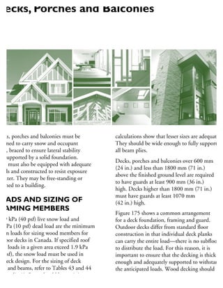
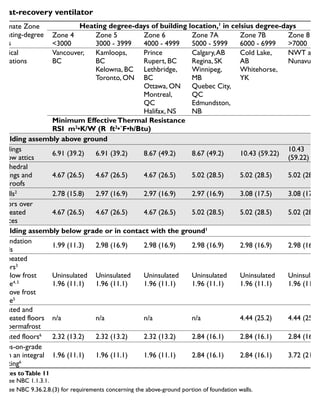
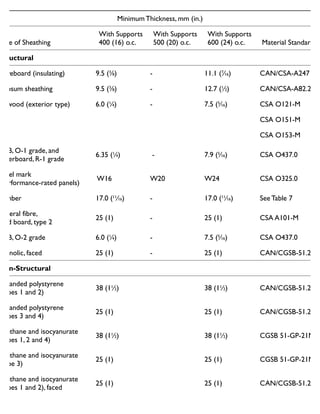
Maximum Height of Exterior Finish Grade Above
Basement Floor or Inside Grade, m (ft.–in.)
Type of
Foundation Wall
Minimum Wall
Thickness, mm (in.)
Foundation Wall Laterally
Unsupported at the Top1 to 4
Foundation Wall Laterally
Supported at the Top1 to 4
Solid concrete,
15 MPa (2,200 psi)
minimum strength
150 (6) 0.80 (2–7) 1.50 (4–11)
200 (8) 1.20 (3–11) 2.15 (7–0)
250 (10) 1.40 (4–7) 2.30 (7–6)
300 (12) 1.50 (4–11) 2.30 (7–6)
Solid concrete,
20 MPa (2,900 psi)
minimum strength
150 (6) 0.80 (2–7) 1.80 (5–10)
200 (8) 1.20 (3–11) 2.30 (7–6)
250 (10) 1.40 (4–7) 2.30 (7–6)
300 (12) 1.50 (4–11) 2.30 (7–6)
Unit masonry 140 (51
⁄2) 0.60 (1–11) 0.80 (2–7)
240 (97
⁄16) 1.20 (3–11) 1.80 (5–10)
290 (117
⁄16) 1.40 (4–7) 2.20 (7–2)
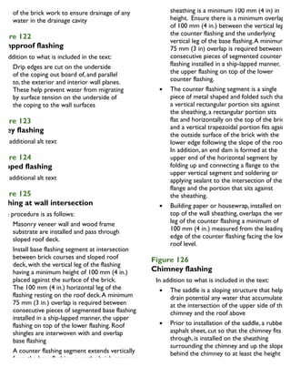
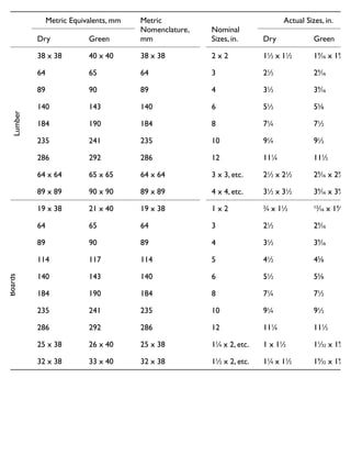
Notes toTable 5
1. Foundation walls are considered laterally supported at the top if the floor joists are embedded in the top of the foundation
walls, or if the floor system is anchored to the top of the foundation walls with anchor bolts, in which case the joists may
run either parallel or perpendicular to the foundation wall.
2. When a foundation wall contains an opening of more than 1.2 m (3 ft.–11 in.) in length or openings in more than 25 per cen
of its length, the portion of the wall beneath such openings is considered laterally unsupported unless the wall around the
opening is reinforced to withstand the earth pressure.
3. When the length of solid wall between windows is less than the average length of the windows, the combined length of
Table 5
Minimum thickness of foundation walls](https://image.slidesharecdn.com/houseframingguidelines-150921192010-lva1-app6891/85/House-framing-guidelines-291-320.jpg)

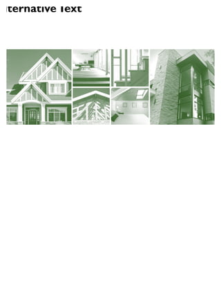
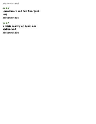
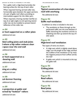
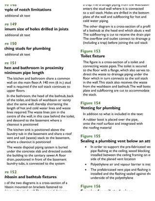
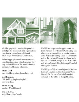
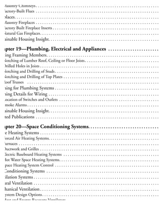
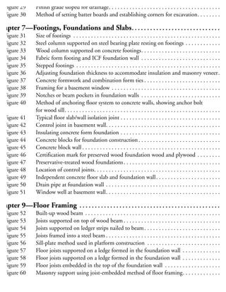
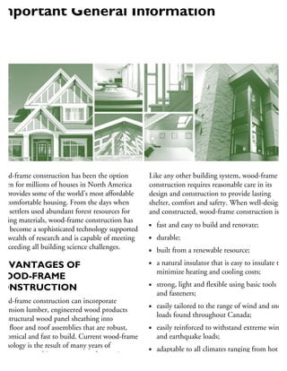
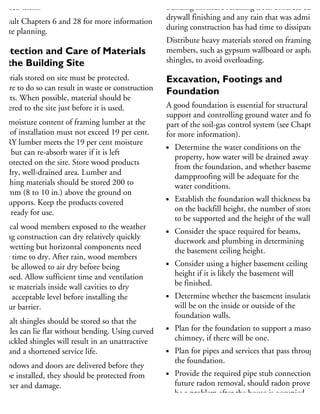
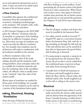
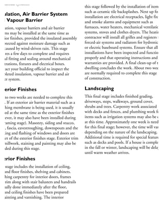
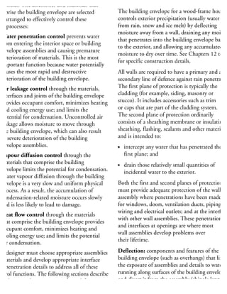
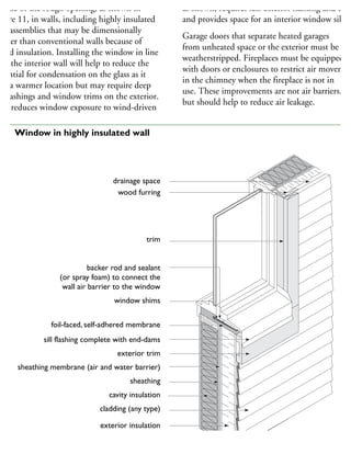
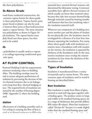
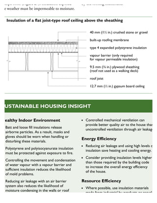
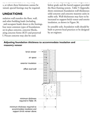
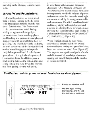
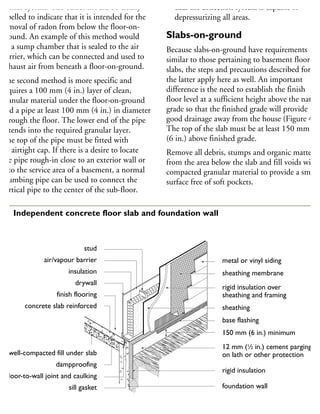
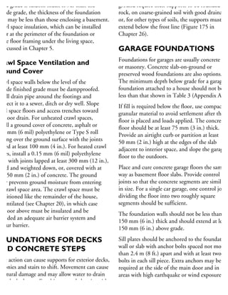
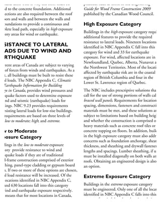
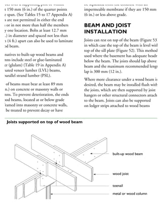
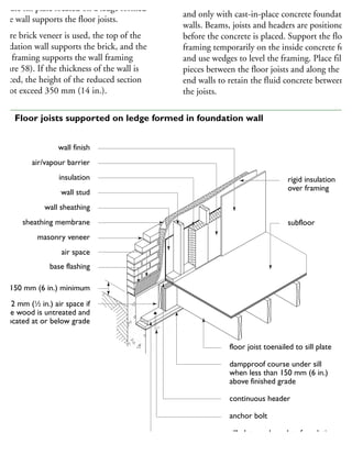
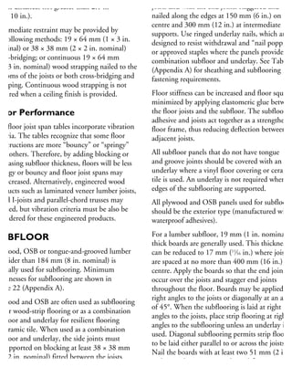
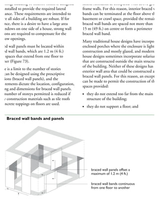
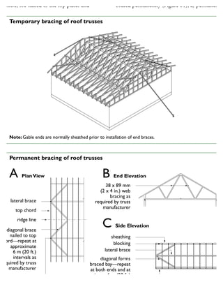
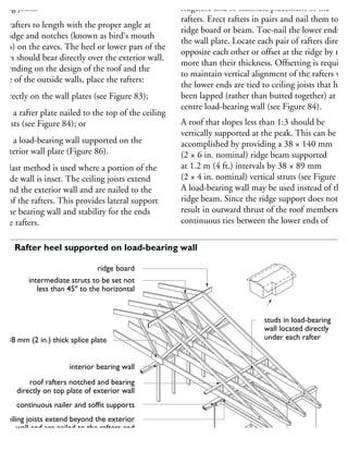
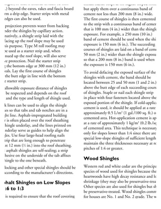
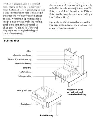
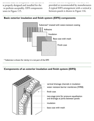
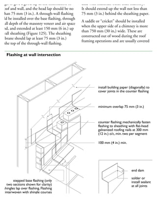
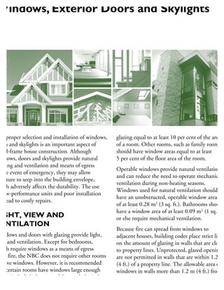
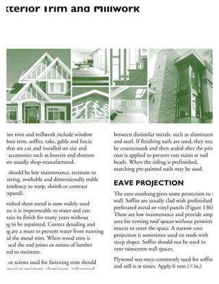
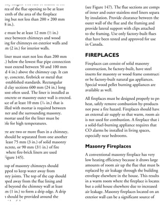
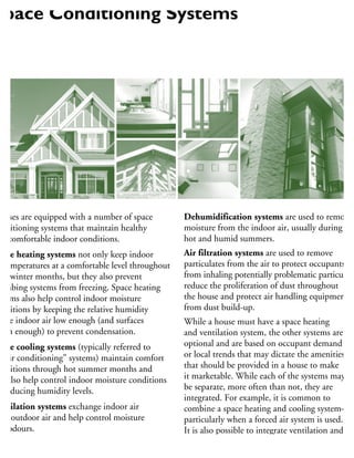
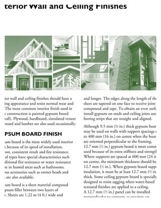
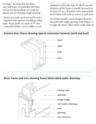
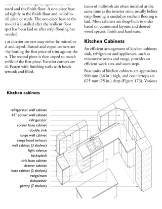
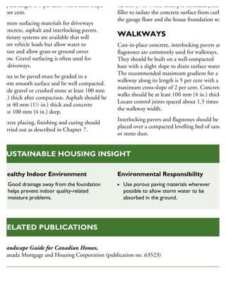
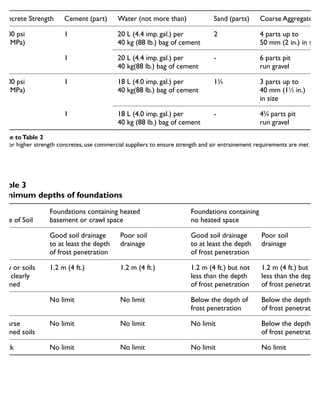
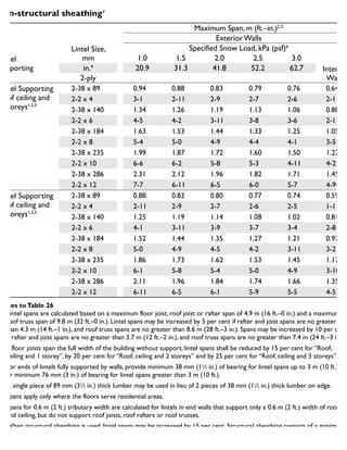
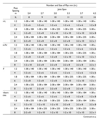
![Commercial
Designation Grade
Joist
Size,
mm
Maximum Span, m (ft.–in.)
Joist Spacing, mm (in.)
With Strapping With Bridging
With Strapping
and Bridging
300 400 600 300 400 600 300 400 600
in. 12 16 24 12 16 24 12 16 24
Douglas fir – larch
(includes Douglas fir
and western larch)
No. 1
and
No. 2
38 x 140 3.09 2.91 2.62 3.29 2.99 2.62 3.29 2.99 2.62
2 x 6 10–2 9–7 8–7 10–10 9–10 8–7 10–10 9–10 8–7
38 x 184 3.71 3.53 3.36 4.00 3.76 3.44 4.19 3.90 3.44
2 x 8 12–2 11–7 11–0 13–1 12–4 11–3 13–9 12–10 11–3
38 x 235 4.38 4.16 3.96 4.66 4.38 4.11 4.84 4.51 4.20
2 x 10 14–4 13–8 13–0 15–3 14–4 13–6 15–10 14–10 13–1
38 x 286 4.99 4.75 4.52 5.26 4.94 4.65 5.43 5.06 4.72
2 x 12 16–5 15–7 14–10 17–2 16–2 15–3 17–10 16–7 15–6
Hem – fir (includes
western hemlock
and amabilis fir)
No. 1
and
No. 2
38 x 140 3.09 2.91 2.62 3.29 2.99 2.62 3.29 2.99 2.62
2 x 6 10-2 9–7 8–7 10–10 9–10 8–7 10–10 9–10 8–7
38 x 184 3.71 3.53 3.36 4.00 3.76 3.44 4.19 3.90 3.44
2 x 8 12–2 11–7 11–0 13–1 12–4 11–3 13–9 12–10 11–3
38 x 235 4.38 4.16 3.96 4.66 4.38 4.11 4.84 4.51 4.20
2 x 10 14–4 13–8 13–0 15–3 14–4 13–6 15–10 14–10 13–1
38 x 286 4.99 4.75 4.52 5.26 4.94 4.65 5.43 5.06 4.72
2 x 12 16–5 15–7 14–10 17–2 16–2 15–3 17–10 16–7 15–6
Spruce, pine, or fir
(includes spruce
[all species except
coast sitka spruce],
jack pine, lodgepole
pine, balsam fir
and alpine fir)
No. 1
and
No. 2
38 x 140 2.92 2.71 2.49 3.14 2.85 2.49 3.14 2.85 2.49
2 x 6 9–7 8–11 8–2 10–4 9–4 8–2 10–4 9–4 8–2
38 x 184 3.54 3.36 3.20 3.81 3.58 3.27 3.99 3.72 3.27
2 x 8 11–7 11–0 10–6 12–5 11–9 10–9 13–1 12–2 10–9
38 x 235 4.17 3.96 3.77 4.44 4.17 3.92 4.60 4.29 4.00
2 x 10 13–8 13–0 12–4 14–6 13–8 12–10 15–1 14–1 13–2
38 x 286 4.75 4.52 4.30 5.01 4.71 4.42 5.17 4.82 4.49
2 x 12 15–7 14–10 14–1 16–4 15–5 14–6 17–0 15–10 14–9
Northern species
(includes any
Canadian species
covered by the
NLGA Standard
Grading Rules)
No. 1
and
No. 2
38 x 140 2.51 2.33 2.16 2.83 2.57 2.25 2.83 2.57 2.25
2 x 6 8–3 7–8 7–1 9–3 8–5 7–5 9–4 8–5 7–5
38 x 184 3.19 3.04 2.84 3.44 3.23 2.96 3.60 3.36 2.96
2 x 8 10–6 10–0 9–4 11–3 10–7 9–8 11–10 11–0 9–8
38 x 235 3.76 3.58 3.41 4.01 3.77 3.54 4.16 3.88 3.62
2 x 10 12–4 11–9 11–2 13–1 12–4 11–7 13–8 12–9 11–1
38 x 286 4.29 4.08 3.88 4.53 4.25 4.00 4.67 4.35 4.06
2 x 12 14–1 13–5 12–9 14–9 13–11 13–1 15–4 14–4 13–4
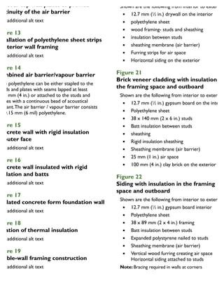
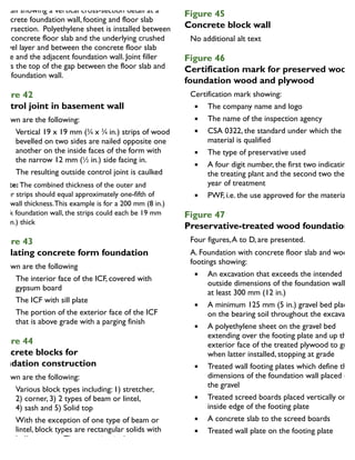
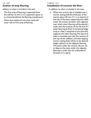
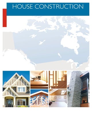
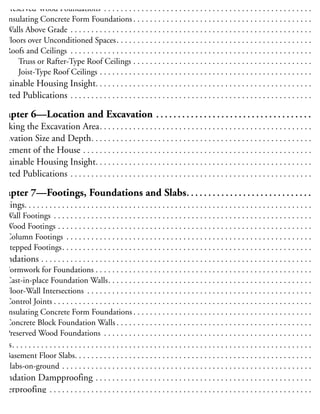
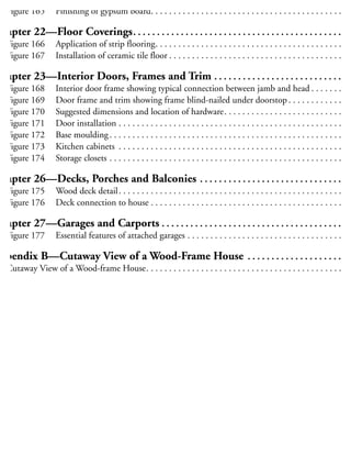
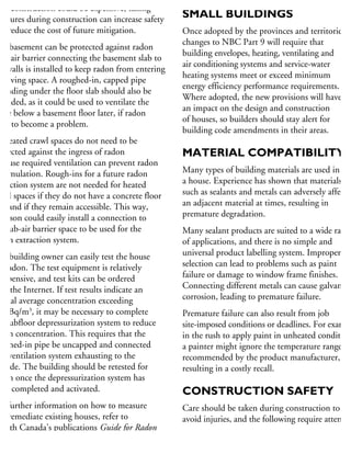
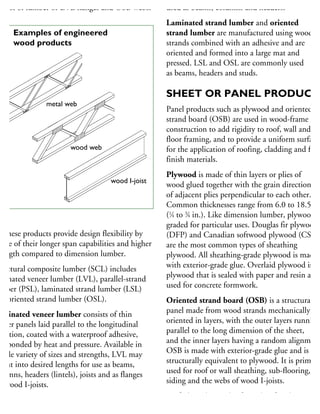
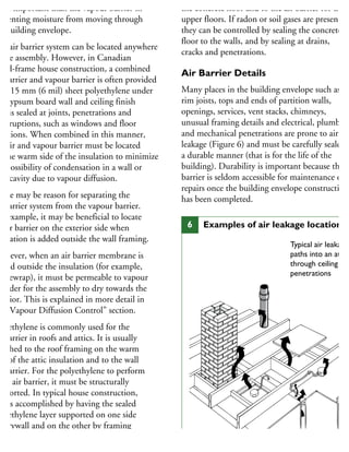
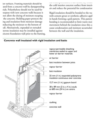
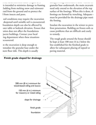
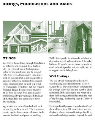
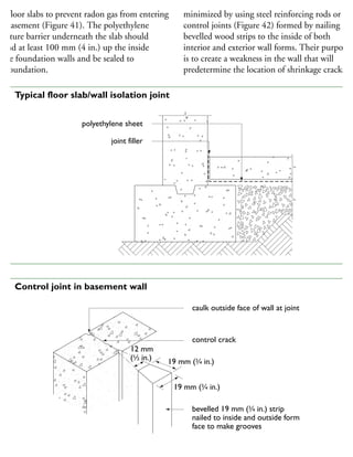
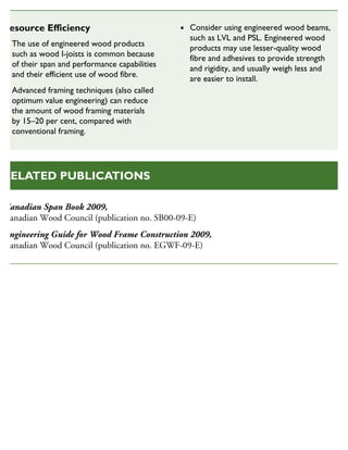
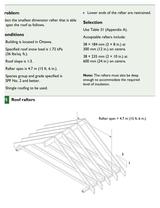
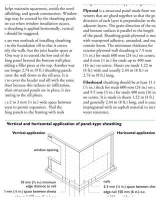
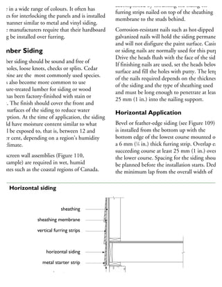
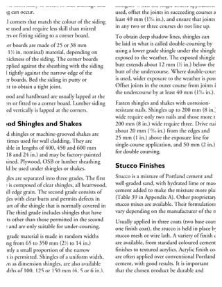
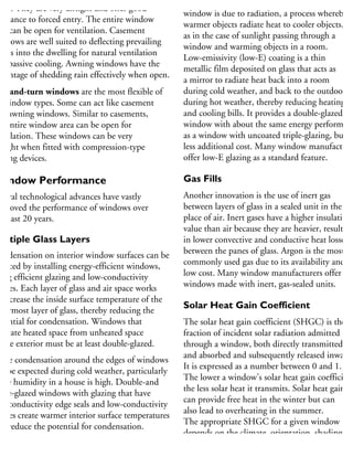
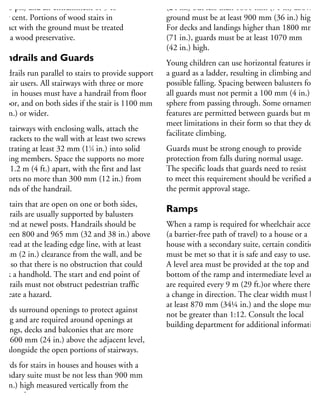
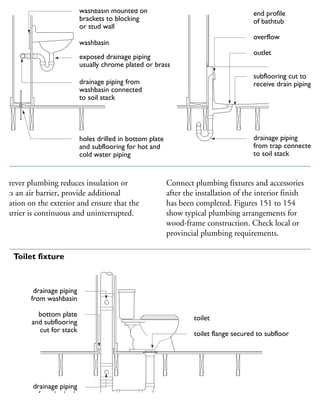
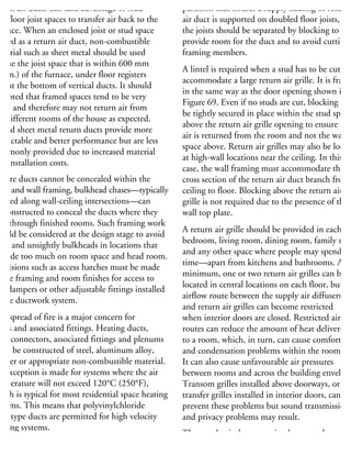
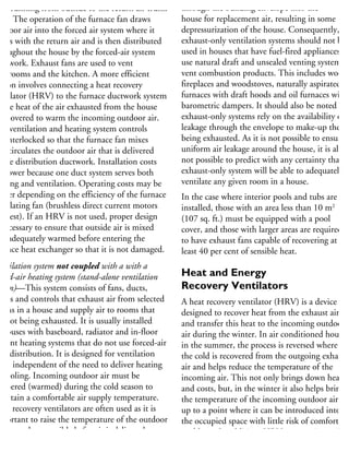
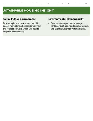
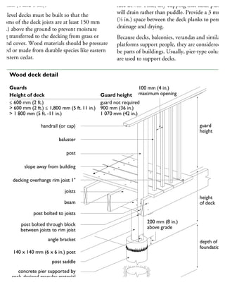
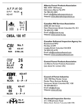
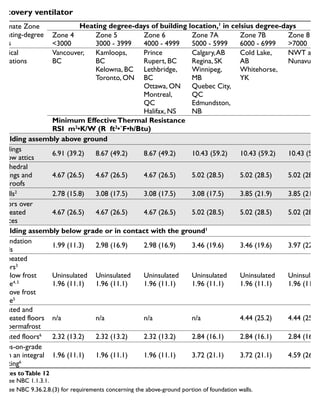
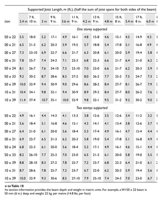
Note toTable 20
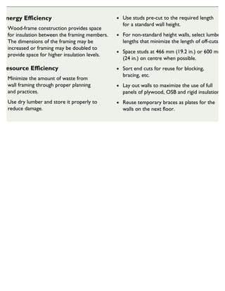
1. Spans apply only where the floors serve residential areas.
2. Subfloor must comply with minimum requirements from Tables 18 and 19.
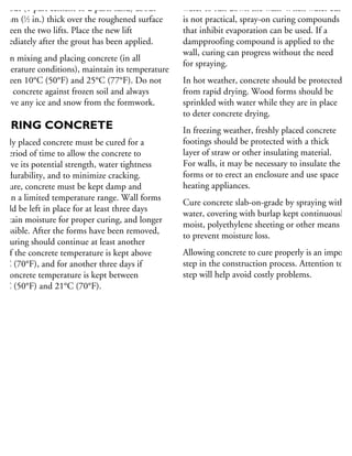
Maximum spans for floor joists – general cases1, 2](https://image.slidesharecdn.com/houseframingguidelines-150921192010-lva1-app6891/85/House-framing-guidelines-311-320.jpg)
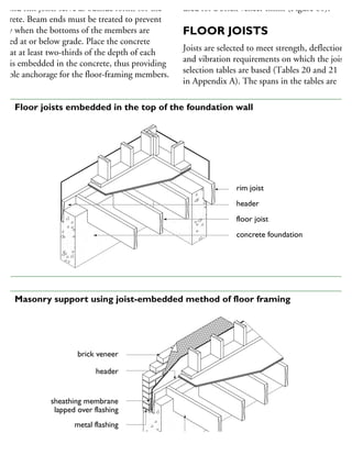
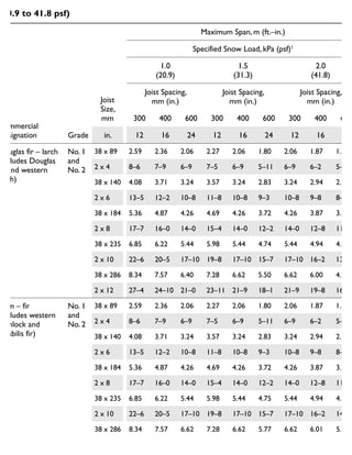
![Commercial
Designation Grade
Joist
Size,
mm
Maximum Span, m (ft.–in.)
Joists with ceilings
attached to Wood Furring
Joists with
concrete topping
Joist Spacing, mm (in.) Joist Spacing, mm (in.)
Without Bridging With Bridging
With or Without
Bridging3
300 400 600 300 400 600 300 400 600
in. 12 16 24 12 16 24 12 16 24
Douglas fir – larch
(includes Douglas fir
and western larch)
No. 1
and
No. 2
38 x 140 3.29 2.99 2.62 3.29 2.99 2.62 3.29 2.99 2.55
2 x 6 10-10 9-10 8-7 10-10 9-10 8-7 10-10 9-10 8-5
38 x 184 4.06 3.83 3.44 4.33 3.93 3.44 4.33 3.81 3.11
2 x 8 13-4 12-7 11-3 14-2 12-11 11-3 14-2 12-6 10-2
38 x 235 4.78 4.50 4.11 5.24 4.98 4.31 5.37 4.65 3.80
2 x 10 15-8 14-9 13-6 17-2 16-4 14-2 17-8 15-3 12-6
38 x 286 5.44 5.12 4.68 5.93 5.64 5.00 6.24 5.40 4.41
2 x 12 17-10 16-10 15-4 19-5 18-6 16-5 20-6 17-9 14-6
Hem – fir (includes
western hemlock
and amabilis fir)
No. 1
and
No. 2
38 x 140 3.29 2.99 2.62 3.29 2.99 2.62 3.29 2.99 2.62
2 x 6 10-10 9-10 8-7 10-10 9-10 8-7 10-10 9-10 8-7
38 x 184 4.06 3.83 3.44 4.33 3.93 3.44 4.33 3.93 3.26
2 x 8 13-4 12-7 11-3 14-2 12-11 11-3 14-2 12-11 10-8
38 x 235 4.78 4.50 4.11 5.24 4.98 4.39 5.53 4.88 3.99
2 x 10 15-8 14-9 13-6 17-2 16-4 14-5 18-2 16-0 13-1
38 x 286 5.44 5.12 4.68 5.93 5.64 5.25 6.54 5.66 4.63
2 x 12 17-10 16-10 15-4 19-5 18-6 17-3 21-6 18-7 15-2
Spruce, pine, or fir
(includes spruce
[all species except
coast sitka spruce],
jack pine, lodgepole
pine, balsam fir
and alpine fir)
No. 1
and
No. 2
38 x 140 3.14 2.85 2.49 3.14 2.85 2.49 3.14 2.85 2.49
2 x 6 10-4 9-4 8-2 10-4 9-4 8-2 10-4 9-4 8-2
38 x 184 3.87 3.64 3.27 4.12 3.75 3.27 4.12 3.75 3.27
2 x 8 12-8 11-11 10-9 13-6 12-4 10-9 13-6 12-4 10-9
38 x 235 4.55 4.28 3.91 4.99 4.75 4.18 5.27 4.79 4.13
2 x 10 14-11 14-1 12-10 16-4 15-7 13-9 17-3 15-8 13-7
38 x 286 5.18 4.88 4.46 5.65 5.37 5.06 6.23 5.81 4.79
2 x 12 17-0 16-0 14-7 18-6 17-7 16-7 20-5 19-1 15-9
Northern species
(includes any
Canadian species
covered by the
NLGA Standard
Grading Rules)
No. 1
and
No. 2
38 x 140 2.83 2.57 2.25 2.83 2.57 2.25 2.83 2.57 2.23
2 x 6 9-4 8-5 7-5 9-4 8-5 7-5 9-4 8-5 7-4
38 x 184 3.50 3.29 2.96 3.72 3.38 2.96 3.72 3.32 2.71
2 x 8 11-6 10-10 9-8 12-3 11-1 9-8 12-3 10-11 8-11
38 x 235 4.11 3.87 3.54 4.51 4.29 3.76 4.69 4.06 3.31
2 x 10 13-6 12-8 11-7 14-9 14-1 12-4 15-4 13-4 10-10
38 x 286 4.68 4.40 4.03 5.10 4.85 4.36 5.44 4.71 3.84
2 x 12 15-4 14-5 13-2 16-9 15-11 14-4 17-10 15-5 12-7
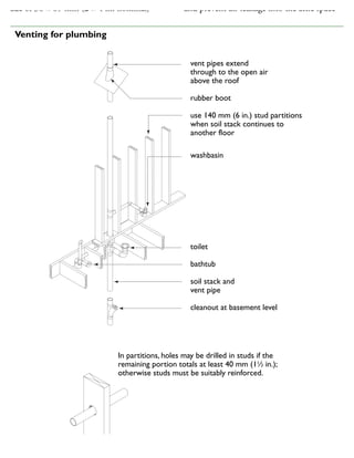
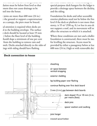
Notes toTable 21
1. Spans apply only where the floors serve residential areas.
2. Subfloor must comply with minimum requirements from Tables 18 and 19.
Maximum spans for floor joists – special cases1, 2](https://image.slidesharecdn.com/houseframingguidelines-150921192010-lva1-app6891/85/House-framing-guidelines-312-320.jpg)
![Commercial
Designation
Lintel Size,
mm
Maximum Span, m (ft.–in.)1, 2,3
Specified Snow Load, kPa (psf)
1.0 1.5 2.0 2.5 3.0
in. 20.9 31.3 41.8 52.2 62.7
Spruce, pine, or fir
(includes Spruce
[all species except
Coast Sitka
Spruce], Jack Pine,
Lodgepole Pine,
Balsam Fir and
Alpine Fir)
3-ply
2.88 2.48 2.21 2.01 1.86
9–6 8–2 7–3 6–7 6–1
38 x 184
4-ply
3.30 2.86 2.55 2.32 2.14
2 x 8 10–10 9–5 8–4 7–7 7–0
5-ply
3.55 3.10 2.82 2.59 2.40
11–8 10–2 9–3 8–6 7–10
3-ply
3.53 3.03 2.70 2.46 2.27
11–7 9–11 8–10 8–1 7–5
38 x 235
4-ply
4.07 3.50 3.12 2.84 2.62
2 x 10 13–4 11–6 10–3 9–4 8–7
5-ply
4.54 3.91 3.43 3.17 2.93
14–11 12–10 11–5 10–5 9–7
3-ply
4.09 3.52 3.13 2.85 2.63
13–9 11–6 10–3 9–4 8–8
38 x 286
4-ply
4.72 4.06 3.62 3.29 3.04
2 x 12 15–6 13–4 11–10 10–10 10–0
5-ply
5.28 4.54 4.04 3.68 3.40
17–4 14–11 13–3 12–1 11–2
Notes toTable 27
1. Beam and lintel spans are calculated based on a maximum supported length of 4.9 m (16 ft.–0 in.). Spans may be increased
by 5 per cent for supported lengths not more than 4.3 m (14 ft.–1 in.), by 10 per cent for supported lengths not more than
3.7 m (12 ft.–2 in.) and by 25 per cent for supported lengths not more than 2.4 m (7 ft.–10 in.).
2. For ridge beams, supported length means half the sum of the rafter, joist or truss span on both sides of the beam. For lintels,
supported length means half the sum of truss, roof joist or rafter spans supported by the lintel plus the length of the
Maximum spans for built-up ridge beams and lintels supporting roof and ceiling
only. No. 1 or No. 2 grade](https://image.slidesharecdn.com/houseframingguidelines-150921192010-lva1-app6891/85/House-framing-guidelines-319-320.jpg)
![Commercial
Designation Grade
Joist
Size,
mm
Maximum Span, m (ft.–in.)
Specified Snow Load, kPa (psf)1
1.0
(20.9)
1.5
(31.3)
2.0
(41.8)
Joist Spacing,
mm (in.)
Joist Spacing,
mm (in.)
Joist Spacing,
mm (in.)
300 400 600 300 400 600 300 400 600
in. 12 16 24 12 16 24 12 16 24
Spruce, pine, or fir
(includes spruce
[all species except
coast sitka
spruce], jack pine,
odgepole pine,
balsam fir and
alpine fir)
No. 1
and
No. 2
38 x 89 2.47 2.24 1.96 2.16 1.96 1.71 1.96 1.78 1.56
2 x 4 8–1 7–4 6–5 7–1 6–5 5–7 6–5 5–10 5–1
38 x 140 3.89 3.53 3.08 3.40 3.08 2.69 3.08 2.80 2.45
2 x 6 12–9 11–7 10–1 11–2 10–1 8–10 10–1 9–2 8–0
38 x 184 5.11 4.64 4.05 4.46 4.05 3.54 4.05 3.68 3.22
2 x 8 16–9 15–3 13–4 14–8 13–4 11–7 13–4 12–1 10–7
38 x 35 6.52 5.93 5.18 5.70 5.18 4.52 5.18 4.70 4.11
2 x 10 21–5 19–5 17–0 18–8 17–0 14–10 17–0 15–5 13–6
38 x 286 7.94 7.21 6.30 6.94 6.30 5.50 6.30 5.73 5.00
2 x 12 26–1 23–8 20–8 22–9 20–8 18–1 20–8 18–9 16–5
Northern species
(includes any
Canadian species
covered by the
NLGA Standard
Grading Rules)
No. 1
and
No. 2
38 x 89 2.23 2.03 1.77 1.95 1.77 1.55 1.77 1.61 1.41
2 x 4 7–4 6–8 5–10 6–5 5–10 5–1 5–10 5–3 4–7
38 x 140 3.51 3.19 2.79 3.07 2.79 2.43 2.79 2.53 2.21
2 x 6 11–6 10–6 9–2 10–1 9–2 8–0 9–2 8–4 7–3
38 x 184 4.61 4.19 3.66 4.03 3.66 3.20 3.66 3.33 2.91
2 x 8 15–2 13–9 12–0 13–3 12–0 10–6 12–0 10–11 9–6
38 x 235 5.89 5.35 4.68 5.15 4.68 4.09 4.68 4.25 3.68
2 x 10 19–4 17–7 15–4 16–11 15–4 13–5 15–4 13–11 12–1
38 x 286 7.17 6.52 5.58 6.26 5.69 4.80 5.69 5.17 4.27
2 x 12 23–6 21–5 18–4 20–7 18–8 15–9 18–8 17–0 14–0
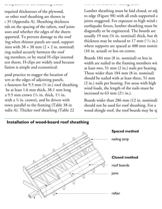
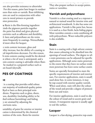
Maximum spans for roof joists – specified roof snow loads 1.0 to 2.0 kPa
(20.9 to 41.8 psf)](https://image.slidesharecdn.com/houseframingguidelines-150921192010-lva1-app6891/85/House-framing-guidelines-322-320.jpg)
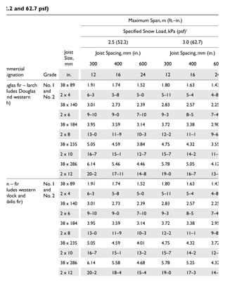
![Commercial
Designation Grade
Joist
Size,
mm
Maximum Span, m (ft.–in.)
Specified Snow Load, kPa (psf)1
2.5 (52.2) 3.0 (62.7)
Joist Spacing,
mm (in.)
Joist Spacing,
mm (in.)
300 400 600 300 400 600
in. 12 16 24 12 16 24
Spruce, pine, or fir
(includes spruce
[all species except
coast sitka
spruce], jack pine,
odgepole pine,
balsam fir and
alpine fir)
No. 1
and
No. 2
38 x 89 1.82 1.65 1.44 1.71 1.56 1.36
2 x 4 6–0 5–5 4–9 5–7 5–1 4–6
38 x 140 2.86 2.60 2.27 2.69 2.45 2.14
2 x 6 9–5 8–6 7–5 8–10 8–0 7–0
38 x 184 3.76 3.42 2.99 3.54 3.22 2.81
2 x 8 12–4 11–3 9–10 11–7 10–7 9–3
38 x 235 4.81 4.37 3.82 4.52 4.11 3.59
2 x 10 15–9 14–4 12–6 14–10 13–6 11–9
38 x 286 5.85 5.31 4.64 5.50 5.00 4.37
2 x 12 19–2 17–5 15–3 18–1 16–5 14–4
Northern species
(includes any
Canadian species
covered by the
NLGA Standard
Grading Rules)
No. 1
and
No. 2
38 x 89 1.64 1.49 1.31 1.55 1.41 1.23
2 x 4 5–5 4–11 4–3 5–1 4–7 4–0
38 x 140 2.59 2.35 2.05 2.43 2.21 1.93
2 x 6 8–6 7–9 6–9 8–0 7–3 6–4
38 x 184 3.40 3.09 2.70 3.20 2.91 2.53
2 x 8 11–2 10–2 8–10 10–6 9–6 8–4
38 x 235 4.34 3.94 3.35 4.09 3.71 3.10
2 x 10 14–3 12–11 11–0 13–5 12–2 10–2
38 x 286 5.28 4.76 3.89 4.97 4.40 3.59
2 x 12 17–4 15–7 12–9 16–4 14–5 11–9
Note toTable 30
Maximum spans for roof joists – specified roof snow loads 2.5 and 3.0 kPa
(52.2 and 62.7 psf)](https://image.slidesharecdn.com/houseframingguidelines-150921192010-lva1-app6891/85/House-framing-guidelines-324-320.jpg)
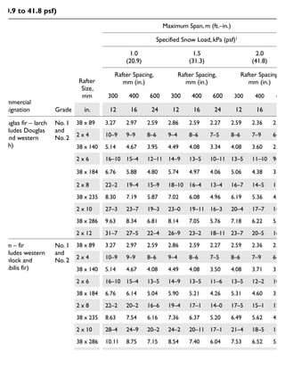
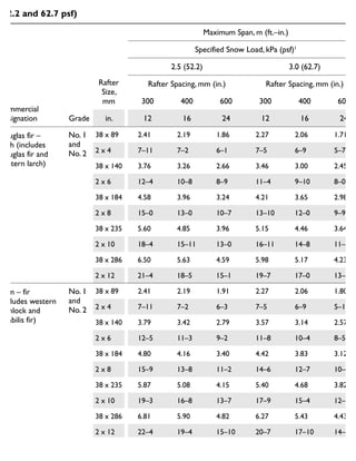
![Commercial
Designation Grade
Rafter
Size,
mm
Maximum Span, m (ft.–in.)
Specified Snow Load, kPa (psf)1
1.0
(20.9)
1.5
(31.3)
2.0
(41.8)
Rafter Spacing,
mm (in.)
Rafter Spacing,
mm (in.)
Rafter Spacing,
mm (in.)
300 400 600 300 400 600 300 400 600
in. 12 16 24 12 16 24 12 16 24
Spruce, pine, or fir
(includes spruce
[all species except
coast sitka
spruce], jack pine,
lodgepole pine,
balsam fir and
alpine fir)
No. 1
and
No. 2
38 x 89 3.11 2.83 2.47 2.72 2.47 2.16 2.47 2.24 1.96
2 x 4 10–3 9–3 8–1 8–11 8–1 7–1 8–1 7–4 6–5
38 x 140 4.90 4.45 3.89 4.28 3.89 3.40 3.89 3.53 3.08
2 x 6 16–1 14–7 12–9 14–0 12–9 11–2 12–9 11–7 10–1
38 x 184 6.44 5.85 5.11 5.62 5.11 4.41 5.11 4.64 3.89
2 x 8 21–1 19–2 16–9 18–5 16–9 14–6 16–9 15–3 12–9
38 x 235 8.22 7.47 6.38 7.18 6.52 5.39 6.52 5.82 4.75
2 x 10 27–0 24–6 20–11 23–7 21–5 17–8 21–5 19–1 15–7
38 x 286 10.00 9.06 7.40 8.74 7.66 6.25 7.80 6.76 5.52
2 x 12 32–10 29–9 24–3 28–8 25–2 20–6 25–7 22–2 18–1
Northern species
(includes any
Canadian species
covered by the
NLGA Standard
Grading Rules)
No. 1
and
No. 2
38 x 89 2.81 2.55 2.23 2.46 2.23 1.95 2.23 2.03 1.77
2 x 4 9–3 8–5 7–4 8–1 7–4 6–5 7–4 6–8 5–10
38 x 140 4.42 4.02 3.44 3.86 3.51 2.91 3.51 3.14 2.56
2 x 6 14–6 13–2 11–3 12–8 11–6 9–6 11–6 10–4 8–5
38 x 184 5.81 5.13 4.19 5.00 4.33 3.54 4.41 3.82 3.12
2 x 8 19–1 16–10 13–9 16–5 14–3 11–7 14–6 12–6 10–3
38 x 235 7.24 6.27 5.12 6.12 5.30 4.33 5.40 4.67 3.82
2 x 10 23–9 20–7 16–10 20–1 17–5 14–2 17–8 15–4 12–6
38 x 286 8.40 7.27 5.94 7.10 6.15 5.02 6.26 5.42 4.43
2 x 12 27–7 23–10 19–6 23–3 20–2 16–6 20–6 17–9 14–6
Maximum spans for roof rafters – specified roof snow loads 1.0 to 2.0 kPa
(20.9 to 41.8 psf)](https://image.slidesharecdn.com/houseframingguidelines-150921192010-lva1-app6891/85/House-framing-guidelines-326-320.jpg)
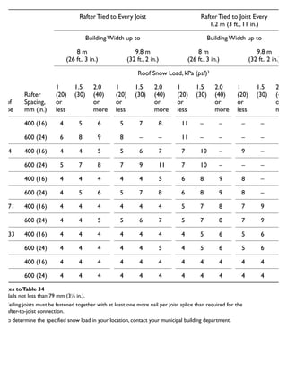
![Commercial
Designation Grade
Rafter
Size,
mm
Maximum Span, m (ft.–in.)
Specified Snow Load, kPa (psf)1
2.5 (52.2) 3.0 (62.7)
Rafter Spacing, mm (in.) Rafter Spacing, mm (in.)
300 400 600 300 400 600
in. 12 16 24 12 16 24
pruce, pine, or fir
includes spruce
all species except
oast sitka spruce],
ack pine, lodgepole
ine, balsam fir and
lpine fir)
No. 1
and
No. 2
38 x 89 2.29 2.08 1.82 2.16 1.96 1.71
2 x 4 7–6 6–10 6–0 7–1 6–5 5–7
38 x 140 3.61 3.28 2.86 3.40 3.08 2.66
2 x 6 11–10 10–9 9–5 11–2 10–1 8–9
38 x 184 4.74 4.31 3.52 4.46 3.96 3.23
2 x 8 15–7 14–2 11–6 14–8 13–0 10–7
38 x 235 6.06 5.27 4.30 5.59 4.84 3.96
2 x 10 19–10 17–3 14–1 18–4 15–11 13–0
38 x 286 7.06 6.11 4.99 6.49 5.62 4.59
2 x 12 23–2 20–1 16–4 21–4 18–5 15–1
Northern species
includes any
Canadian species
overed by the
NLGA Standard
Grading Rules)
No. 1
and
No. 2
38 x 89 2.07 1.88 1.62 1.95 1.77 1.49
2 x 4 6–10 6–2 5–4 6–5 5–10 4–11
38 x 140 3.26 2.84 2.32 3.02 2.61 2.13
2 x 6 10–8 9–4 7–7 9–11 8–7 7–0
38 x 184 3.99 3.46 2.82 3.67 3.18 2.60
2 x 8 13–1 11–4 9–3 12–1 10–5 8–6
38 x 235 4.88 4.23 3.45 4.49 3.89 3.17
2 x 10 16–0 13–10 11–4 14–9 12–9 10–5
38 x 286 5.66 4.90 4.00 5.21 4.51 3.68
2 x 12 18–7 16–1 13–2 17–1 14–10 12–1
Note toTable 32
1. To determine the specified snow load in your location, contact your municipal building department.
Maximum spans for roof rafters – specified roof snow loads 2.5 and 3.0 kPa
(52.2 and 62.7 psf)](https://image.slidesharecdn.com/houseframingguidelines-150921192010-lva1-app6891/85/House-framing-guidelines-328-320.jpg)
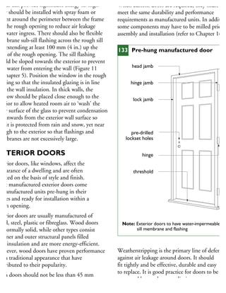
![Commercial
Designation Grade
Joist Size,
mm (in.)
Maximum Span, m (ft.–in.)
Joist Spacing, mm (in.)
300 (12) 400 (16) 600 (24)
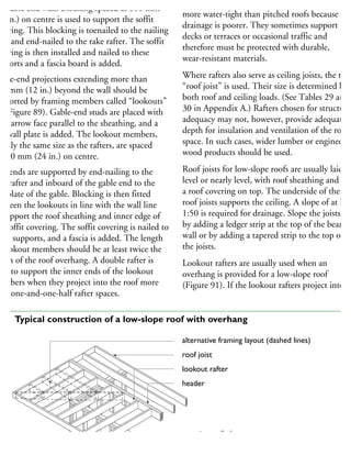
Douglas fir – larch
(includes Douglas
fir and western
larch)
No. 1
and
No. 2
38 x 89 (2 x 4) 3.27 (10–9) 2.97 (9–9) 2.59 (8–6)
38 x 140 (2 x 6) 5.14 (16–10) 4.67 (15–4) 4.08 (13–5)
38 x 184 (2 x 8) 6.76 (22–2) 6.14 (20–2) 5.36 (17–7)
38 x 235 (2 x 10) 8.63 (28–4) 7.84 (25–9) 6.85 (22–6)
38 x 286 (2 x 12) 10.50 (34–5) 9.54 (31–3) 8.34 (27–4)
Hem – fir
(includes western
hemlock and
amabilis fir)
No. 1
and
No. 2
38 x 89 (2 x 4) 3.27 (10–9) 2.97 (9–9) 2.59 (8–6)
38 x 140 (2 x 6) 5.14 (16–10) 4.67 (15–4) 4.08 (13–5)
38 x 184 (2 x 8) 6.76 (22–2) 6.14 (20–2) 5.36 (17–7)
38 x 235 (2 x 10) 8.63 (28–4) 7.84 (25–9) 6.85 (22–6)
38 x 286 (2 x 12) 10.50 (34–5) 9.54 (31–3) 8.34 (27–4)
Spruce, pine, or fir
(includes spruce
[all species except
coast sitka spruce],
jack pine, lodgepole
pine, balsam fir and
alpine fir)
No. 1
and
No. 2
38 x 89 (2 x 4) 3.11 (10–3) 2.83 (9–3) 2.47 (8–1)
38 x 140 (2 x 6) 4.90 (16–1) 4.45 (14–7) 3.89 (12–9)
38 x 184 (2 x 8) 6.44 (21–1) 5.85 (19–2) 5.11 (16–9 )
38 x 235 (2 x 10) 8.22 (27–0) 7.47 (24–6) 6.52 (21–5)
38 x 286 (2 x 12) 10.00 (32–10) 9.09 (29–10) 7.94 (26–1)
Northern Species
(includes any
Canadian species
covered by the
NLGA Standard
Grading Rules)
No. 1
and
No. 2
38 x 89 (2 x 4) 2.81 (9–3) 2.55 (8–5) 2.23 (7–4 )
38 x 140 (2 x 6) 4.42 (14–6) 4.02 (13–2) 3.51 (11–6)
38 x 184 (2 x 8) 5.81 (19–1) 5.28 (17–4) 4.61 (15–2)
38 x 235 (2 x 10) 7.42 (24–4) 6.74 (22–2) 5.89 (19–4)
38 x 286 (2 x 12) 9.03 (29–8) 8.21 (26–11) 7.17 (23–6)
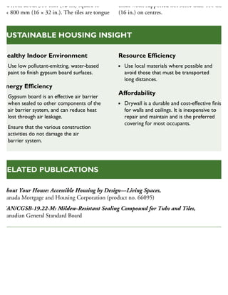
Maximum spans for ceiling joists – attic not accessible by a stairway](https://image.slidesharecdn.com/houseframingguidelines-150921192010-lva1-app6891/85/House-framing-guidelines-329-320.jpg)
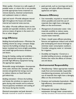
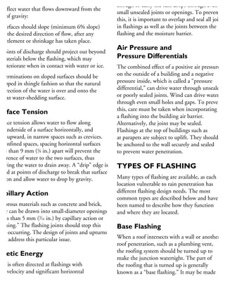
![Joist Size
mm
Joist span, m (ft.–in.)
Joists not incised Joists incised
Joist spacing, mm (in.)
400 600 400 600
in. 16 24 16 24
Douglas fir - larch
(includes Douglas fir
and western larch)
38 x 140 2.9 2.3 2.6 2.2
2 x 6 9-6 7-6 8-6 7-2
38 x 184 3.5 2.8 3.2 2.6
2 x 8 11-6 9.2 10-6 8-6
38 x 235 4.3 3.5 3.9 3.2
2 x 10 14-1 11-6 12-9 10-6
Hem - fir (includes
western hemlock
and amabilis fir)
38 x 140 2.9 2.5 2.8 2.3
2 x 6 9-6 8-2 9-2 7-6
38 x 184 3.7 3.0 3.4 2.7
2 x 8 12-1 9-9 11-2 8-10
38 x 235 4.3 3.6 4.1 3.4
2 x 10 14-1 11-9 13-4 11-2
Spruce, pine, or fir
(includes spruce
[all species except
coast sitka spruce],
jack pine, lodgeploe
pine, balsam fir and
alpine fir)
38 x 140 2.8 2.4 2.7 2.3
2 x 6 9-2 7-10 8-10 7-6
38 x 184 3.7 3.1 3.5 2.8
2 x 8 12-1 10-2 11-6 9-2
38 x 235 4.3 3.8 4.3 3.5
2 x 10 14-1 12-6 14-1 11-6
Northern Species
(includes any
Canadian species
covered by the
NLGA Standard
Grading Rules
38 x 140 2.5 2.0 2.3 1.9
2 x 6 8-2 6-7 7-6 6-2
38 x 184 3.0 2.5 2.8 2.3
2 x 8 9-9 8-2 9-2 7-6
38 x 235 3.7 3.0 3.4 2.8
2 x 10 12-1 9-9 11-2 9-2
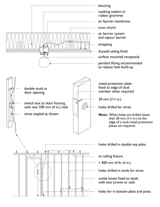
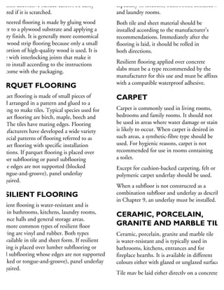
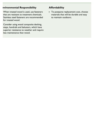
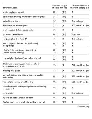
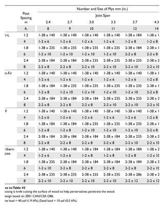
Notes toTable 44
1. Incising is knife cutting the surface of wood to help perservatives penetrate the wood.
2. Design based on 2001 CAN / CSA O86
Joists for exterior decks](https://image.slidesharecdn.com/houseframingguidelines-150921192010-lva1-app6891/85/House-framing-guidelines-338-320.jpg)