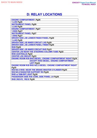
1. This document provides information on the electrical system of the Toyota Hilux, including wiring diagrams and relay locations.
2. It describes the location of relays, junction blocks, and other electrical components throughout the vehicle, such as in the engine compartment, instrument panel, and various body panels.
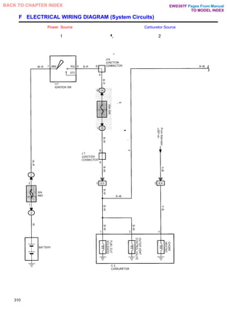
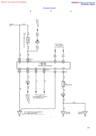
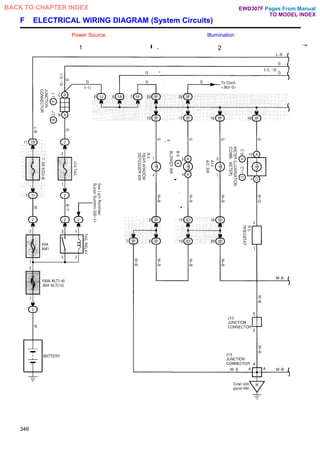
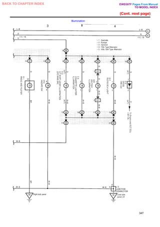
3. The wiring diagrams show the electrical circuits and connections between systems, with wiring routes and connector details. Abbreviations and how to use the manual are also explained.
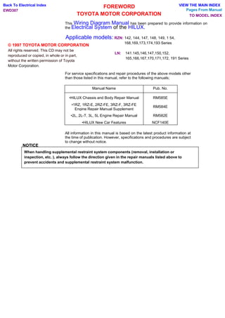
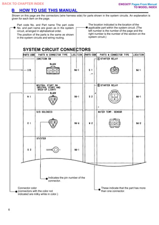
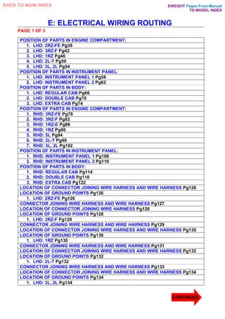
![A: The same code occurring on the next page indicates
that the wire harness is continuous.
B: Number of the section of the system circuit (S);
C: System Title
D: Indicates the wiring color.
Wire colors are indicated by an alphabetical code.
B = Black L = Blue R = Red
BR - Brown LG - Light Green V = Violet
G = Green 0 = Orange W - White
GR = Gray P = Pink Y - Yellow
The first letter indicates the basic wire color and the
second letter indicates the color of the stripe.
Example: L - Y
E: Represents a part.
The position of the parts is the same as shown in the
system circuits and wiring routing.
F: Indicates the pin number of the connector. The
numbering system is different for female and male
connectors.
Example: Numbered in order Numbered in order
from upper left to from upper right to
lower riqht lower left
G: Indicates a Relay Block. No shading is used and
only the Relay Block No. is shown to distinguish it
from the J/B.
Example: CD Indicates Relay Block No. 1.
H: When 2 parts both use one connector in common,
the parts connector name used in the wire routing
section is shown in square brackets [ ].
- HINT:
I: Junction Block (The number in the circle is the J/B
No. and the connector code is shown beside it).
Junction Blocks are shaded to clearly separate them
from other parts.
Example:
3B indicates
that it is inside
Junction Block
No. 3.
J: Indicates related system.
K: The left number is the number of the page and the
right number is the number of the section on the
system circuit.
L: Indicates the wiring harness and wiring harness
connector. The wiring harness with male terminal is
shown with arrows (^). Outside numerals are pin
numbers.
M: ( ) is used to indicate different wiring and
connector, etc. when the vehicle model, engine
type, or specification is different.
N: Indicates a shielded cable.
O: Indicates a ground point.
P: Page No.
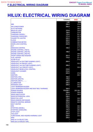
Junction connector (code: J 1 to J23) in this manual include a
short terminal which is connected to a number of wire
harnesses. Always perform inspection with the short terminal
installed. (When installing the wire harnesses, the harnesses
can be connected to any position within the short terminal
grouping. Accordingly, in other vehicles, the same position in
the short terminal may be connected to a wire harness from a
different part.) Wire harness sharing the same short terminal
grouping have the same color.
5
Pages From Manual
TO MODEL INDEX
BACK TO CHAPTER INDEX
B
EWD307F](https://image.slidesharecdn.com/hiluxelecricalewd307f-220728231702-87b21402/85/HILUX-ELECRICAL-EWD307F-pdf-5-320.jpg)
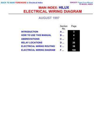
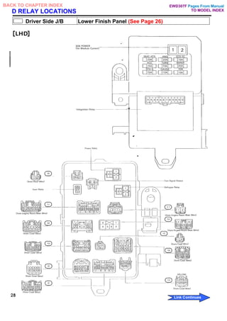
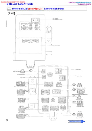
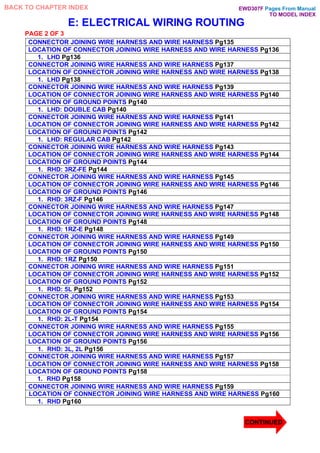
![D: RELAY LOCATIONS
[Engine Compartment]
(LHD)
26
Pages From Manual
TO MODEL INDEX
BACK TO CHAPTER INDEX
Link Continues
EWD307F
To: ST-11 ST-14
To: Sup. 2L,2L-T,3L,5L](https://image.slidesharecdn.com/hiluxelecricalewd307f-220728231702-87b21402/85/HILUX-ELECRICAL-EWD307F-pdf-9-320.jpg)
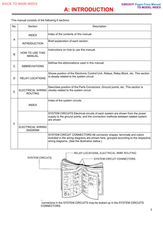
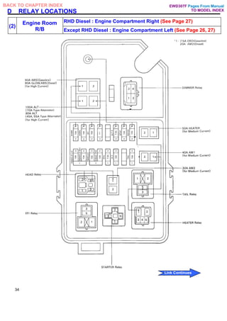
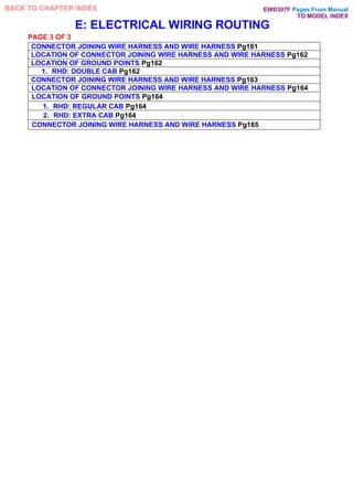
![D
[Engine Compartment]
(RHD)
27
Pages From Manual
TO MODEL INDEX
BACK TO CHAPTER INDEX
Link Continues
EWD307F
To: ST-11 ST-14
To: Sup. 2L,2L-T,3L,5L](https://image.slidesharecdn.com/hiluxelecricalewd307f-220728231702-87b21402/85/HILUX-ELECRICAL-EWD307F-pdf-10-320.jpg)
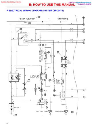
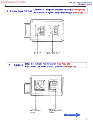
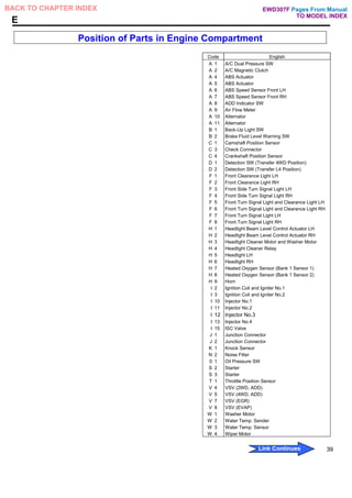
![D
[Driver Side J/B Inner Circuit] [LHD]
29
Pages From Manual
TO MODEL INDEX
BACK TO CHAPTER INDEX EWD307F
Link Continues](https://image.slidesharecdn.com/hiluxelecricalewd307f-220728231702-87b21402/85/HILUX-ELECRICAL-EWD307F-pdf-12-320.jpg)
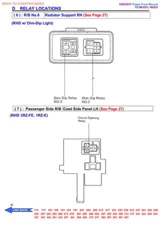
![D
[Driver Side J/B Inner Circuit] [RHD]
31
Pages From Manual
TO MODEL INDEX
BACK TO CHAPTER INDEX
Link Continues
EWD307F](https://image.slidesharecdn.com/hiluxelecricalewd307f-220728231702-87b21402/85/HILUX-ELECRICAL-EWD307F-pdf-14-320.jpg)
![D RELAY LOCATIONS
Center J/B Near The Steering Column Tube (See Page 27)
[RHD Australia]
32
Pages From Manual
TO MODEL INDEX
BACK TO CHAPTER INDEX
Link Continues
EWD307F](https://image.slidesharecdn.com/hiluxelecricalewd307f-220728231702-87b21402/85/HILUX-ELECRICAL-EWD307F-pdf-15-320.jpg)
![D
[Center J/B Inner Circuit]
33
BACK TO CHAPTER INDEX
Link Continues
Pages From Manual
TO MODEL INDEX
EWD307F](https://image.slidesharecdn.com/hiluxelecricalewd307f-220728231702-87b21402/85/HILUX-ELECRICAL-EWD307F-pdf-16-320.jpg)
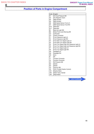
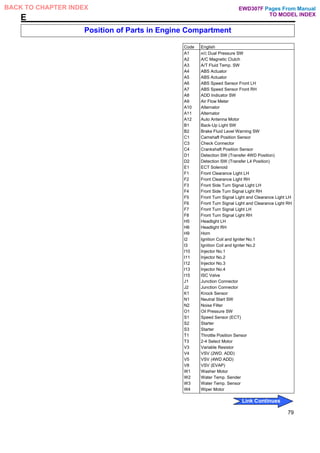
![E ELECTRICAL WIRING ROUTING
Position of Parts in Engine Compartment
[LHD:2RZ-FE] *1 : w/o ABS
*2 : w/ ABS
*3: Europe
*4: Except Europe
38
Pages From Manual
TO MODEL INDEX
BACK TO CHAPTER INDEX
Link Continues
EWD307F](https://image.slidesharecdn.com/hiluxelecricalewd307f-220728231702-87b21402/85/HILUX-ELECRICAL-EWD307F-pdf-23-320.jpg)
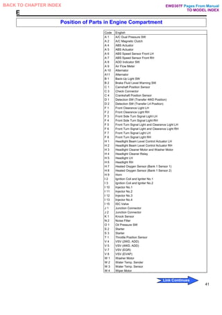
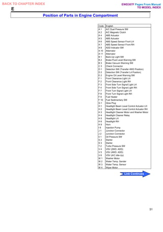
![E ELECTRICAL WIRING ROUTING
Position of Parts in Engine Compartment
[LHD:2RZ-FE] *1 : w/o ABS
*2.: w/ ABS
*3: Europe
*4: Except Europe
40
Pages From Manual
TO MODEL INDEX
BACK TO CHAPTER INDEX
Link Continues
EWD307F](https://image.slidesharecdn.com/hiluxelecricalewd307f-220728231702-87b21402/85/HILUX-ELECRICAL-EWD307F-pdf-25-320.jpg)
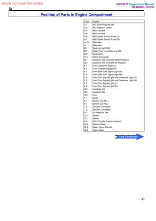
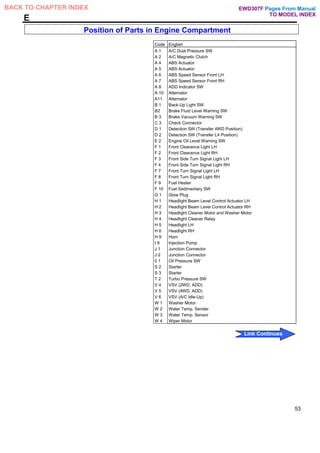
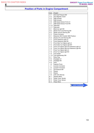
![E ELECTRICAL WIRING ROUTING
Position of Parts in Engine Compartment
[LHD:3RZ-F]
42
Pages From Manual
TO MODEL INDEX
BACK TO CHAPTER INDEX
Link Continues
EWD307F](https://image.slidesharecdn.com/hiluxelecricalewd307f-220728231702-87b21402/85/HILUX-ELECRICAL-EWD307F-pdf-27-320.jpg)
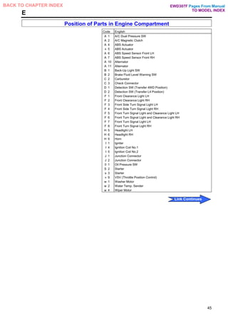
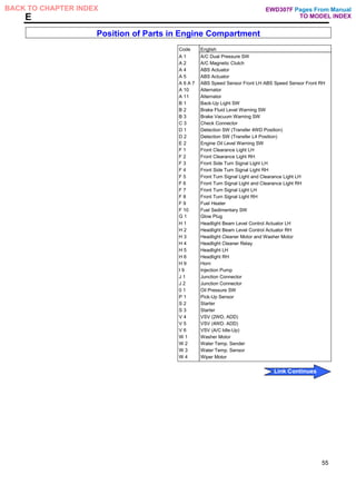
![E ELECTRICAL WIRING ROUTING
Position of Parts in Engine Compartment
[LHD:3RZ-F]
44
Pages From Manual
TO MODEL INDEX
BACK TO CHAPTER INDEX
Link Continues
EWD307F](https://image.slidesharecdn.com/hiluxelecricalewd307f-220728231702-87b21402/85/HILUX-ELECRICAL-EWD307F-pdf-29-320.jpg)
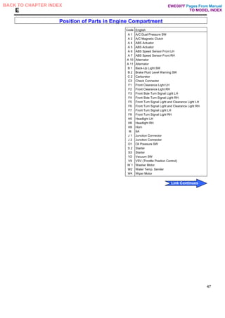
![E ELECTRICAL WIRING ROUTING
Position of Parts in Engine Compartment
[LHD:1RZ]
46
Pages From Manual
TO MODEL INDEX
BACK TO CHAPTER INDEX
Link Continues
EWD307F](https://image.slidesharecdn.com/hiluxelecricalewd307f-220728231702-87b21402/85/HILUX-ELECRICAL-EWD307F-pdf-31-320.jpg)
![E ELECTRICAL WIRING ROUTING
Position of Parts in Engine Compartment
[LHD:1RZ]
48
Pages From Manual
TO MODEL INDEX
BACK TO CHAPTER INDEX
Link Continues
EWD307F](https://image.slidesharecdn.com/hiluxelecricalewd307f-220728231702-87b21402/85/HILUX-ELECRICAL-EWD307F-pdf-33-320.jpg)
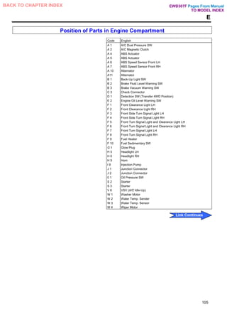
![E ELECTRICAL WIRING ROUTING
Position of Parts in Engine Compartment
[LHD:2L-T]
50
Pages From Manual
TO MODEL INDEX
BACK TO CHAPTER INDEX
Link Continues
EWD307F](https://image.slidesharecdn.com/hiluxelecricalewd307f-220728231702-87b21402/85/HILUX-ELECRICAL-EWD307F-pdf-35-320.jpg)
![E ELECTRICAL WIRING ROUTING
Position of Parts in Engine Compartment
[LHD:2L-T]
52
Pages From Manual
TO MODEL INDEX
BACK TO CHAPTER INDEX
Link Continues
EWD307F](https://image.slidesharecdn.com/hiluxelecricalewd307f-220728231702-87b21402/85/HILUX-ELECRICAL-EWD307F-pdf-37-320.jpg)
![E ELECTRICAL WIRING ROUTING
Position of Parts in Engine Compartment
[LHD:3L,2L]
54
Pages From Manual
TO MODEL INDEX
BACK TO CHAPTER INDEX
Link Continues
EWD307F
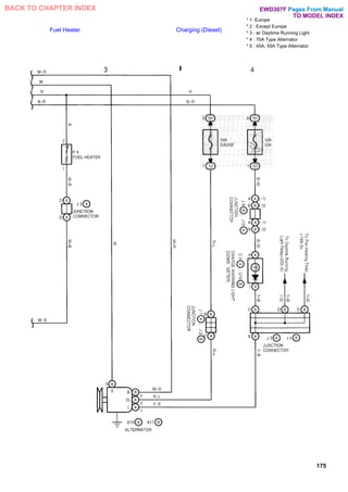
Fuel Heater
G 1 Glow Plug
S 2 Starter
S 3 Starter
ST-50
ST-50
To: Sup. 2L,2L-T,3L,5L](https://image.slidesharecdn.com/hiluxelecricalewd307f-220728231702-87b21402/85/HILUX-ELECRICAL-EWD307F-pdf-39-320.jpg)
![E ELECTRICAL WIRING ROUTING
Position of Parts in Engine Compartment
[LHD:3L,2L]
56
Pages From Manual
TO MODEL INDEX
BACK TO CHAPTER INDEX
Link Continues
EWD307F](https://image.slidesharecdn.com/hiluxelecricalewd307f-220728231702-87b21402/85/HILUX-ELECRICAL-EWD307F-pdf-41-320.jpg)
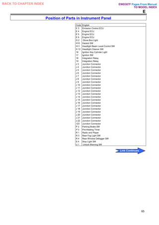
![E ELECTRICAL WIRING ROUTING
Position of Parts in Instrument Panel
[LHD: lnstrument Panel 1]
58
1 :2-Door
Pages From Manual
TO MODEL INDEX
BACK TO CHAPTER INDEX
Link Continues
EWD307F](https://image.slidesharecdn.com/hiluxelecricalewd307f-220728231702-87b21402/85/HILUX-ELECRICAL-EWD307F-pdf-43-320.jpg)
![E ELECTRICAL WIRING ROUTING
Position of Parts in Instrument Panel
[LHD:lnstrument Panel 1]
60
Pages From Manual
TO MODEL INDEX
BACK TO CHAPTER INDEX
Link Continues
EWD307F](https://image.slidesharecdn.com/hiluxelecricalewd307f-220728231702-87b21402/85/HILUX-ELECRICAL-EWD307F-pdf-45-320.jpg)
![E ELECTRICAL WIRING ROUTING
Position of Parts in Instrument Panel
[LHD:lnstrument Panel 2]
62
Pages From Manual
TO MODEL INDEX
BACK TO CHAPTER INDEX
Link Continues
EWD307F](https://image.slidesharecdn.com/hiluxelecricalewd307f-220728231702-87b21402/85/HILUX-ELECRICAL-EWD307F-pdf-47-320.jpg)
![E ELECTRICAL WIRING ROUTING
Position of Parts in Instrument Panel
[LHD:lnstrument Panel 2]
64
Pages From Manual
TO MODEL INDEX
BACK TO CHAPTER INDEX
Link Continues
EWD307F](https://image.slidesharecdn.com/hiluxelecricalewd307f-220728231702-87b21402/85/HILUX-ELECRICAL-EWD307F-pdf-49-320.jpg)
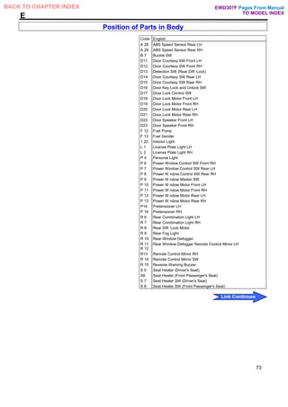
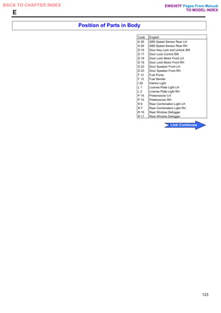
![E ELECTRICAL WIRING ROUTING
[LHD:Regular Cab]
Position of Parts in Body
*1 : w/ Vent Window
*2 : w/o Vent Window
66
Pages From Manual
TO MODEL INDEX
BACK TO CHAPTER INDEX
Link Continues
EWD307F](https://image.slidesharecdn.com/hiluxelecricalewd307f-220728231702-87b21402/85/HILUX-ELECRICAL-EWD307F-pdf-51-320.jpg)
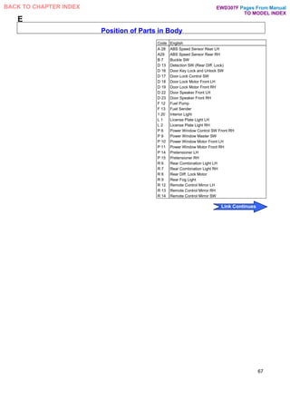
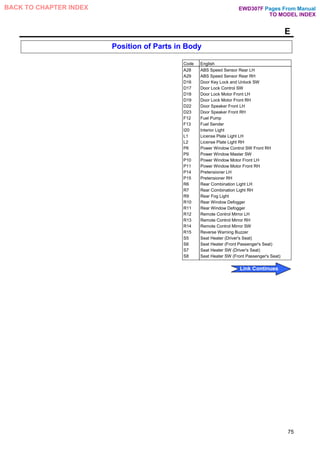
![E ELECTRICAL WIRING ROUTING
Position of Parts in Body
[LHD:Regular Cab] *1 : w/ Vent Window
*2 : w/o Vent Window
68
Pages From Manual
TO MODEL INDEX
BACK TO CHAPTER INDEX
Link Continues
EWD307F](https://image.slidesharecdn.com/hiluxelecricalewd307f-220728231702-87b21402/85/HILUX-ELECRICAL-EWD307F-pdf-53-320.jpg)
![E ELECTRICAL WIRING ROUTING
Position of Parts in Body
[LHD:Double Cab] *1 : General
*2: Except General
*3 : w/ Vent Window
*4 : w/o Vent Window
70
Pages From Manual
TO MODEL INDEX
BACK TO CHAPTER INDEX
Link Continues
EWD307F](https://image.slidesharecdn.com/hiluxelecricalewd307f-220728231702-87b21402/85/HILUX-ELECRICAL-EWD307F-pdf-55-320.jpg)
![E ELECTRICAL WIRING ROUTING
Position of Parts in Body
[LHD:Double Cab]
*1 : General
*2 : Except General
*3 : w/ Vent Window
*4 : w/o Vent Window
72
Pages From Manual
TO MODEL INDEX
BACK TO CHAPTER INDEX
Link Continues
EWD307F](https://image.slidesharecdn.com/hiluxelecricalewd307f-220728231702-87b21402/85/HILUX-ELECRICAL-EWD307F-pdf-57-320.jpg)
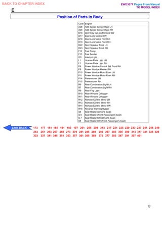
![E ELECTRICAL WIRING ROUTING
Position of Parts in Body
[LHD:Extra Cab]
*1 : w/ Vent Window
*2 : w/o Vent Window
74
Pages From Manual
TO MODEL INDEX
BACK TO CHAPTER INDEX
Link Continues
EWD307F](https://image.slidesharecdn.com/hiluxelecricalewd307f-220728231702-87b21402/85/HILUX-ELECRICAL-EWD307F-pdf-59-320.jpg)
![E ELECTRICAL WIRING ROUTING
Position of Parts in Body
[LHD: Extra Cab]
* 1 : w/ Vent Window
*2 : w/o Vent Window
76
Pages From Manual
TO MODEL INDEX
BACK TO CHAPTER INDEX
Link Continues
EWD307F](https://image.slidesharecdn.com/hiluxelecricalewd307f-220728231702-87b21402/85/HILUX-ELECRICAL-EWD307F-pdf-61-320.jpg)
![E ELECTRICAL WIRING ROUTING
Position of Parts in Engine Compartment
[RHD:3RZ-FE] *1 : w/ 2-4 Select SW
*2 : w/o 2-4 Select SW
78
Pages From Manual
TO MODEL INDEX
BACK TO CHAPTER INDEX
Link Continues
EWD307F](https://image.slidesharecdn.com/hiluxelecricalewd307f-220728231702-87b21402/85/HILUX-ELECRICAL-EWD307F-pdf-63-320.jpg)
![E ELECTRICAL WIRING ROUTING
Position of Parts in Engine Compartment
[RHD:3RZ-FE] *1 : w/ 2-4 Select SW
*2 : w/o 2-4 Select SW
80
Pages From Manual
TO MODEL INDEX
BACK TO CHAPTER INDEX
Link Continues
EWD307F](https://image.slidesharecdn.com/hiluxelecricalewd307f-220728231702-87b21402/85/HILUX-ELECRICAL-EWD307F-pdf-65-320.jpg)
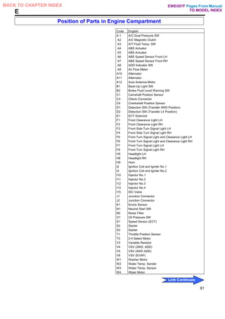
![E ELECTRICAL WIRING ROUTING
Position of Parts in Engine Compartment
[RHD:3RZ-F]
82
Pages From Manual
TO MODEL INDEX
BACK TO CHAPTER INDEX
Link Continues
EWD307F](https://image.slidesharecdn.com/hiluxelecricalewd307f-220728231702-87b21402/85/HILUX-ELECRICAL-EWD307F-pdf-67-320.jpg)
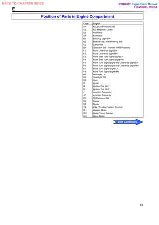
![E ELECTRICAL WIRING ROUTING
Position of Parts in Engine Compartment
[RHD:3RZ-F]
84
Pages From Manual
TO MODEL INDEX
BACK TO CHAPTER INDEX
Link Continues
EWD307F](https://image.slidesharecdn.com/hiluxelecricalewd307f-220728231702-87b21402/85/HILUX-ELECRICAL-EWD307F-pdf-69-320.jpg)
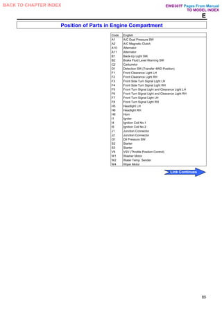
![E ELECTRICAL WIRING ROUTING
Position of Parts in Engine Compartment
[RHD:1RZ-E]
88
Pages From Manual
TO MODEL INDEX
BACK TO CHAPTER INDEX
Link Continues
EWD307F](https://image.slidesharecdn.com/hiluxelecricalewd307f-220728231702-87b21402/85/HILUX-ELECRICAL-EWD307F-pdf-71-320.jpg)
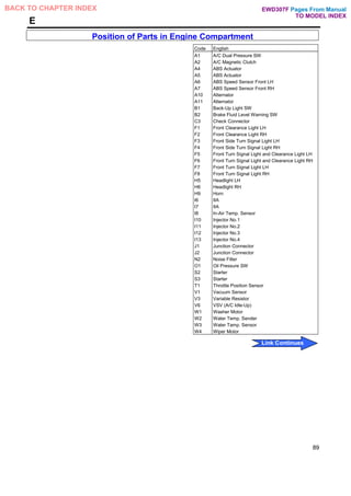
![E ELECTRICAL WIRING ROUTING
Position of Parts in Engine Compartment
[RHD:1RZ]
90
Pages From Manual
TO MODEL INDEX
BACK TO CHAPTER INDEX
Link Continues
EWD307F](https://image.slidesharecdn.com/hiluxelecricalewd307f-220728231702-87b21402/85/HILUX-ELECRICAL-EWD307F-pdf-73-320.jpg)
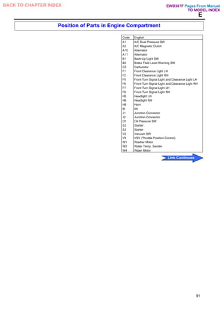
![E ELECTRICAL WIRING ROUTING
Position of Parts in Engine Compartment
[RHD:1RZ]
92
Pages From Manual
TO MODEL INDEX
BACK TO CHAPTER INDEX
Link Continues
EWD307F](https://image.slidesharecdn.com/hiluxelecricalewd307f-220728231702-87b21402/85/HILUX-ELECRICAL-EWD307F-pdf-75-320.jpg)
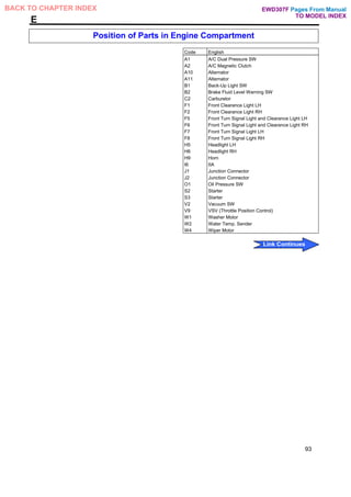
![E ELECTRICAL WIRING ROUTING
Position of Parts in Engine Compartment
[RHD:5L]
*1 : w/ 2-4 Select SW
*2 : w/o 2-4 Select SW
94
Pages From Manual
TO MODEL INDEX
BACK TO CHAPTER INDEX
Link Continues
EWD307F](https://image.slidesharecdn.com/hiluxelecricalewd307f-220728231702-87b21402/85/HILUX-ELECRICAL-EWD307F-pdf-77-320.jpg)
![E ELECTRICAL WIRING ROUTING
Position of Parts in Engine Compartment
[RHD:5L] *1 : w/ 2-4 Select SW
*2 : w/o 2-4 Select SW
96
Pages From Manual
TO MODEL INDEX
BACK TO CHAPTER INDEX
Link Continues
EWD307F](https://image.slidesharecdn.com/hiluxelecricalewd307f-220728231702-87b21402/85/HILUX-ELECRICAL-EWD307F-pdf-79-320.jpg)
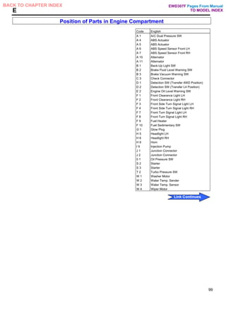
![E ELECTRICAL WIRING ROUTING
Position of Parts in Engine Compartment
[RHD:2L-T]
98
Pages From Manual
TO MODEL INDEX
BACK TO CHAPTER INDEX
Link Continues
EWD307F](https://image.slidesharecdn.com/hiluxelecricalewd307f-220728231702-87b21402/85/HILUX-ELECRICAL-EWD307F-pdf-81-320.jpg)
![E ELECTRICAL WIRING ROUTING
Position of Parts in Engine Compartment
[RHD:2L-T]
100
Pages From Manual
TO MODEL INDEX
BACK TO CHAPTER INDEX
Link Continues
EWD307F](https://image.slidesharecdn.com/hiluxelecricalewd307f-220728231702-87b21402/85/HILUX-ELECRICAL-EWD307F-pdf-83-320.jpg)
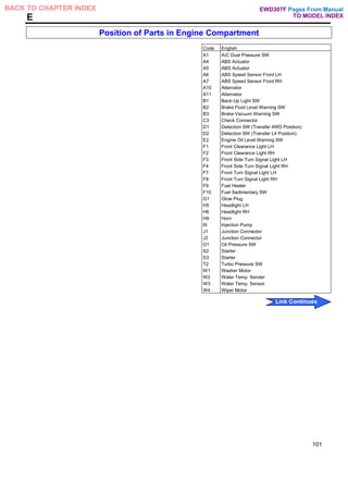
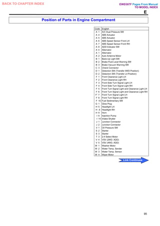
![E ELECTRICAL WIRING ROUTING
Position of Parts in Engine Compartment
[RHD:3L,2L]
102
Pages From Manual
TO MODEL INDEX
BACK TO CHAPTER INDEX
Link Continues
EWD307F
Fuel Heater
G 1 Glow Plug
S 2: Starter
S 3: Starter
To: Sup. 2L,2L-T,3L,5L](https://image.slidesharecdn.com/hiluxelecricalewd307f-220728231702-87b21402/85/HILUX-ELECRICAL-EWD307F-pdf-85-320.jpg)
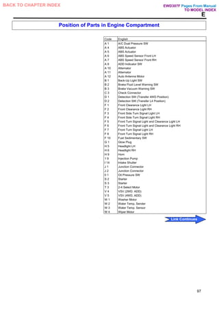
![E ELECTRICAL WIRING ROUTING
Position of Parts in Engine Compartment
[RHD:3L,2L]
104
Pages From Manual
TO MODEL INDEX
BACK TO CHAPTER INDEX
Link Continues
EWD307F](https://image.slidesharecdn.com/hiluxelecricalewd307f-220728231702-87b21402/85/HILUX-ELECRICAL-EWD307F-pdf-87-320.jpg)
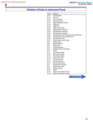
![E ELECTRICAL WIRING ROUTING
Position of Parts in Instrument Panel
[RHD:lnstrument Panel 1] *1 :2-Door
106
Pages From Manual
TO MODEL INDEX
BACK TO CHAPTER INDEX
Link Continues
EWD307F](https://image.slidesharecdn.com/hiluxelecricalewd307f-220728231702-87b21402/85/HILUX-ELECRICAL-EWD307F-pdf-89-320.jpg)
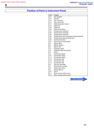
![E ELECTRICAL WIRING ROUTING
Position of Parts in Instrument Panel
[RHD:lnstrument Panel 1] *1 :2-Door
108
Pages From Manual
TO MODEL INDEX
BACK TO CHAPTER INDEX
Link Continues
EWD307F](https://image.slidesharecdn.com/hiluxelecricalewd307f-220728231702-87b21402/85/HILUX-ELECRICAL-EWD307F-pdf-91-320.jpg)
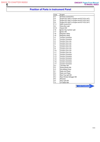
![E ELECTRICAL WIRING ROUTING
Position of Parts in Instrument Panel
[RHD:lnstrument Panel 2]
110
Pages From Manual
TO MODEL INDEX
BACK TO CHAPTER INDEX
Link Continues
EWD307F](https://image.slidesharecdn.com/hiluxelecricalewd307f-220728231702-87b21402/85/HILUX-ELECRICAL-EWD307F-pdf-93-320.jpg)
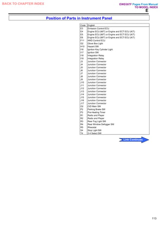
![E ELECTRICAL WIRING ROUTING
Position of Parts in Instrument Panel
[RH D: Instrument Panel 2]
112
Pages From Manual
TO MODEL INDEX
BACK TO CHAPTER INDEX
Link Continues
EWD307F](https://image.slidesharecdn.com/hiluxelecricalewd307f-220728231702-87b21402/85/HILUX-ELECRICAL-EWD307F-pdf-95-320.jpg)
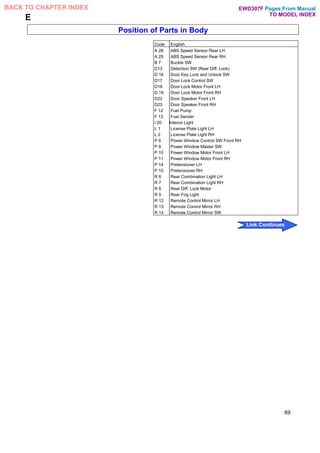
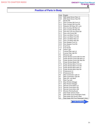
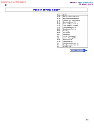
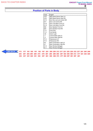
![E ELECTRICAL WIRING ROUTING
Position of Parts in Body
[RHD:Regular Cab]
114
Pages From Manual
TO MODEL INDEX
BACK TO CHAPTER INDEX
Link Continues
EWD307F](https://image.slidesharecdn.com/hiluxelecricalewd307f-220728231702-87b21402/85/HILUX-ELECRICAL-EWD307F-pdf-97-320.jpg)
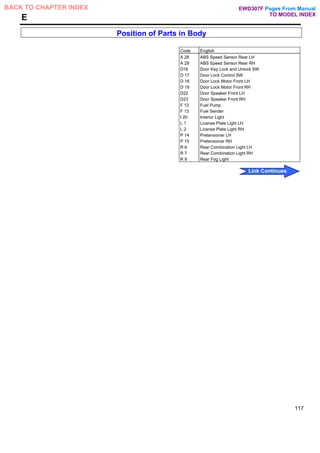
![E ELECTRICAL WIRING ROUTING
Position of Parts in Body
[RHD:Regular Cab]
116
Pages From Manual
TO MODEL INDEX
BACK TO CHAPTER INDEX
Link Continues
EWD307F](https://image.slidesharecdn.com/hiluxelecricalewd307f-220728231702-87b21402/85/HILUX-ELECRICAL-EWD307F-pdf-99-320.jpg)
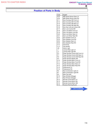
![E ELECTRICAL WIRING ROUTING
Position of Parts in Body
[RHD:Double Cab] *1:General
*2:Except
118
Pages From Manual
TO MODEL INDEX
BACK TO CHAPTER INDEX
Link Continues
EWD307F](https://image.slidesharecdn.com/hiluxelecricalewd307f-220728231702-87b21402/85/HILUX-ELECRICAL-EWD307F-pdf-101-320.jpg)
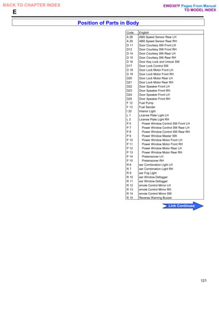
![E ELECTRICAL WIRING ROUTING
Position of Parts in Body
[RHD:Double Cab] *1:General
*2:Except General
120
Pages From Manual
TO MODEL INDEX
BACK TO CHAPTER INDEX
Link Continues
EWD307F](https://image.slidesharecdn.com/hiluxelecricalewd307f-220728231702-87b21402/85/HILUX-ELECRICAL-EWD307F-pdf-103-320.jpg)
![E ELECTRICAL WIRING ROUTING
Position of Parts in Body
[RHD:Extra Cab]
122
Pages From Manual
TO MODEL INDEX
BACK TO CHAPTER INDEX
Link Continues
EWD307F](https://image.slidesharecdn.com/hiluxelecricalewd307f-220728231702-87b21402/85/HILUX-ELECRICAL-EWD307F-pdf-105-320.jpg)
![E ELECTRICAL WIRING ROUTING
Position of Parts in Body
[RHD:Extra Cab]
124
Pages From Manual
TO MODEL INDEX
BACK TO CHAPTER INDEX
Link Continues
EWD307F](https://image.slidesharecdn.com/hiluxelecricalewd307f-220728231702-87b21402/85/HILUX-ELECRICAL-EWD307F-pdf-107-320.jpg)
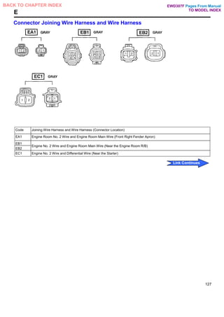
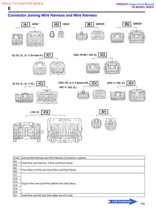
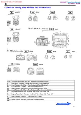
![E ELECTRICAL WIRING ROUTING
: Location of Connector Joining Wire Harness and Wire Harness
: Location of Ground Points
[LHD:2RZ-FE]
126
Pages From Manual
TO MODEL INDEX
BACK TO CHAPTER INDEX
Link Continues
EWD307F](https://image.slidesharecdn.com/hiluxelecricalewd307f-220728231702-87b21402/85/HILUX-ELECRICAL-EWD307F-pdf-109-320.jpg)
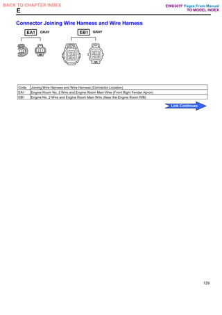
![E ELECTRICAL WIRING ROUTING
: Location of Connector Joining Wire Harness and Wire Harness
: Location of Ground Points
[LHD:3RZ-F]
128
Pages From Manual
TO MODEL INDEX
BACK TO CHAPTER INDEX
Link Continues
EWD307F](https://image.slidesharecdn.com/hiluxelecricalewd307f-220728231702-87b21402/85/HILUX-ELECRICAL-EWD307F-pdf-111-320.jpg)
![E ELECTRICAL WIRING ROUTING
: Location of Connector Joining Wire Harness and Wire Harness
: Location of Ground Points
[LHD:1RZ]
130
Pages From Manual
TO MODEL INDEX
BACK TO CHAPTER INDEX
Link Continues
EWD307F](https://image.slidesharecdn.com/hiluxelecricalewd307f-220728231702-87b21402/85/HILUX-ELECRICAL-EWD307F-pdf-113-320.jpg)
![E ELECTRICAL WIRING ROUTING
: Location of Connector Joining Wire Harness and Wire Harness
: Location of Ground Points
[LHD:2L-T]
132
Pages From Manual
TO MODEL INDEX
BACK TO CHAPTER INDEX
Link Continues
EWD307F](https://image.slidesharecdn.com/hiluxelecricalewd307f-220728231702-87b21402/85/HILUX-ELECRICAL-EWD307F-pdf-115-320.jpg)
![E ELECTRICAL WIRING ROUTING
: Location of Connector Joining Wire Harness and Wire Harness
: Location of Ground Points
[LHD:3L,2L]
134
Pages From Manual
TO MODEL INDEX
BACK TO CHAPTER INDEX
Link Continues
EWD307F](https://image.slidesharecdn.com/hiluxelecricalewd307f-220728231702-87b21402/85/HILUX-ELECRICAL-EWD307F-pdf-117-320.jpg)
![E ELECTRICAL WIRING ROUTING
: Location of Connector Joining Wire Harness and Wire Harness
: Location of Ground Points
[LHD]
136
Pages From Manual
TO MODEL INDEX
BACK TO CHAPTER INDEX
Link Continues
EWD307F](https://image.slidesharecdn.com/hiluxelecricalewd307f-220728231702-87b21402/85/HILUX-ELECRICAL-EWD307F-pdf-119-320.jpg)
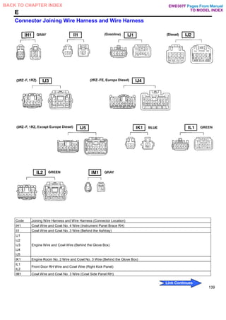
![E ELECTRICAL WIRING ROUTING
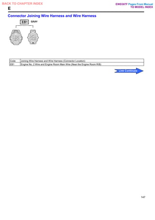
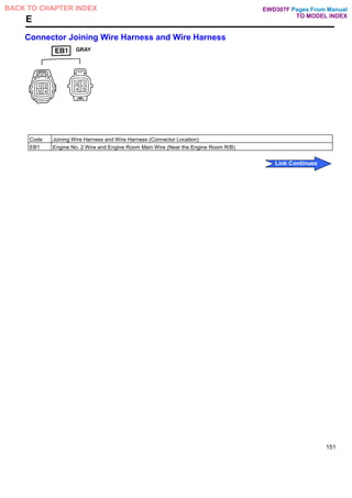
: Location of Connector Joining Wire Harness and Wire Harness
[LHD]
138
Pages From Manual
TO MODEL INDEX
BACK TO CHAPTER INDEX
Link Continues
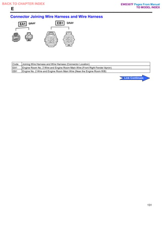
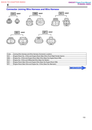
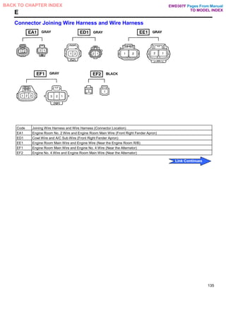
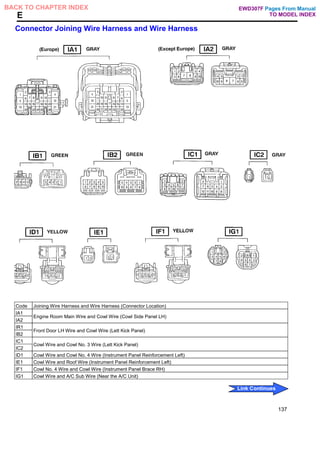
EWD307F](https://image.slidesharecdn.com/hiluxelecricalewd307f-220728231702-87b21402/85/HILUX-ELECRICAL-EWD307F-pdf-121-320.jpg)
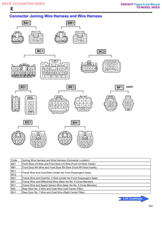
![E ELECTRICAL WIRING ROUTING
: Location of Connector Joining Wire Harness and Wire Harness
: Location of Ground Points
[LHD:Double Cab]
140
Pages From Manual
TO MODEL INDEX
BACK TO CHAPTER INDEX
Link Continues
EWD307F](https://image.slidesharecdn.com/hiluxelecricalewd307f-220728231702-87b21402/85/HILUX-ELECRICAL-EWD307F-pdf-123-320.jpg)
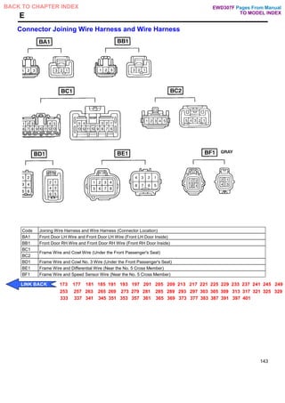
![E ELECTRICAL WIRING ROUTING
: Location of Connector Joining Wire Harness and Wire Harness
: Location of Ground Points
[LHD:Regular Cab]
[LHD: Extra Cab]
142
Pages From Manual
TO MODEL INDEX
BACK TO CHAPTER INDEX
Link Continues
EWD307F](https://image.slidesharecdn.com/hiluxelecricalewd307f-220728231702-87b21402/85/HILUX-ELECRICAL-EWD307F-pdf-125-320.jpg)
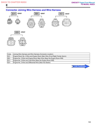
![E ELECTRICAL WIRING ROUTING
: Location of Connector Joining Wire Harness and Wire Harness
: Location of Ground Points
[RHD:3RZ-FE]
144
Pages From Manual
TO MODEL INDEX
BACK TO CHAPTER INDEX
Link Continues
EWD307F](https://image.slidesharecdn.com/hiluxelecricalewd307f-220728231702-87b21402/85/HILUX-ELECRICAL-EWD307F-pdf-127-320.jpg)
![E ELECTRICAL WIRING ROUTING
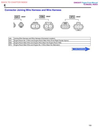
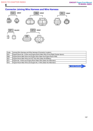
: Location of Connector Joining Wire Harness and Wire Harness
: Location of Ground Points
[RHD:3RZ-F]
146
Pages From Manual
TO MODEL INDEX
BACK TO CHAPTER INDEX
Link Continues
EWD307F](https://image.slidesharecdn.com/hiluxelecricalewd307f-220728231702-87b21402/85/HILUX-ELECRICAL-EWD307F-pdf-129-320.jpg)
![E ELECTRICAL WIRING ROUTING
: Location of Connector Joining Wire Harness and Wire Harness
: Location of Ground Points
[RHD:1RZ-E]
148
Pages From Manual
TO MODEL INDEX
BACK TO CHAPTER INDEX
Link Continues
EWD307F](https://image.slidesharecdn.com/hiluxelecricalewd307f-220728231702-87b21402/85/HILUX-ELECRICAL-EWD307F-pdf-131-320.jpg)

![E ELECTRICAL WIRING ROUTING
: Location of Connector Joining Wire Harness and Wire Harness
: Location of Ground Points
[RHD:1RZ]
150
Pages From Manual
TO MODEL INDEX
BACK TO CHAPTER INDEX
Link Continues
EWD307F](https://image.slidesharecdn.com/hiluxelecricalewd307f-220728231702-87b21402/85/HILUX-ELECRICAL-EWD307F-pdf-133-320.jpg)
![E ELECTRICAL WIRING ROUTING
: Location of Connector Joining Wire Harness and Wire Harness
: Location of Ground Points
[RHD:5L]
152
Pages From Manual
TO MODEL INDEX
BACK TO CHAPTER INDEX
Link Continues
EWD307F](https://image.slidesharecdn.com/hiluxelecricalewd307f-220728231702-87b21402/85/HILUX-ELECRICAL-EWD307F-pdf-135-320.jpg)

![E ELECTRICAL WIRING ROUTING
: Location of Connector Joining Wire Harness and Wire Harness
: Location of Ground Points
[RHD:2L-T]
154
Pages From Manual
TO MODEL INDEX
BACK TO CHAPTER INDEX
Link Continues
EWD307F](https://image.slidesharecdn.com/hiluxelecricalewd307f-220728231702-87b21402/85/HILUX-ELECRICAL-EWD307F-pdf-137-320.jpg)
![E ELECTRICAL WIRING ROUTING
: Location of Connector Joining Wire Harness and Wire Harness
: Location of Ground Points
[RHD:3L,2L]
156
Pages From Manual
TO MODEL INDEX
BACK TO CHAPTER INDEX
Link Continues
EWD307F](https://image.slidesharecdn.com/hiluxelecricalewd307f-220728231702-87b21402/85/HILUX-ELECRICAL-EWD307F-pdf-139-320.jpg)
![E ELECTRICAL WIRING ROUTING
: Location of Connector Joining Wire Harness and Wire Harness
: Location of Ground Points
[RHD]
158
Pages From Manual
TO MODEL INDEX
BACK TO CHAPTER INDEX
Link Continues
EWD307F](https://image.slidesharecdn.com/hiluxelecricalewd307f-220728231702-87b21402/85/HILUX-ELECRICAL-EWD307F-pdf-141-320.jpg)
![E ELECTRICAL WIRING ROUTING
: Location of Connector Joining Wire Harness and Wire Harness
[RHD]
160
Pages From Manual
TO MODEL INDEX
BACK TO CHAPTER INDEX
Link Continues
EWD307F](https://image.slidesharecdn.com/hiluxelecricalewd307f-220728231702-87b21402/85/HILUX-ELECRICAL-EWD307F-pdf-143-320.jpg)
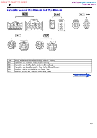
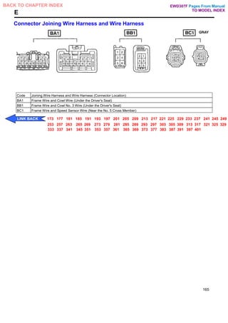
![E ELECTRICAL WIRING ROUTING
: Location of Connector Joining Wire Harness and Wire Harness
: Location of Ground Points
[RHD:Double Cab]
162
Pages From Manual
TO MODEL INDEX
BACK TO CHAPTER INDEX
Link Continues
EWD307F](https://image.slidesharecdn.com/hiluxelecricalewd307f-220728231702-87b21402/85/HILUX-ELECRICAL-EWD307F-pdf-145-320.jpg)
![E ELECTRICAL WIRING ROUTING
: Location of Connector Joining Wire Harness and Wire Harness
: Location of Ground Points
[RHD:Regular Cab]
[RHD:Extra Cab]
164
Pages From Manual
TO MODEL INDEX
BACK TO CHAPTER INDEX
Link Continues
EWD307F](https://image.slidesharecdn.com/hiluxelecricalewd307f-220728231702-87b21402/85/HILUX-ELECRICAL-EWD307F-pdf-147-320.jpg)
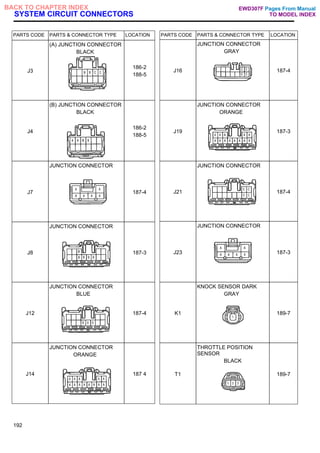
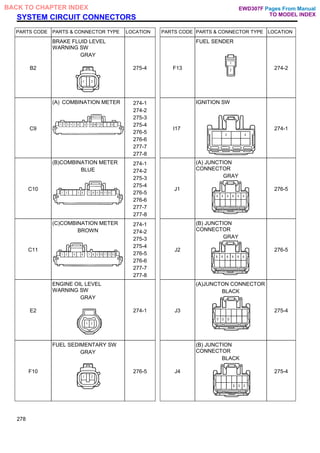
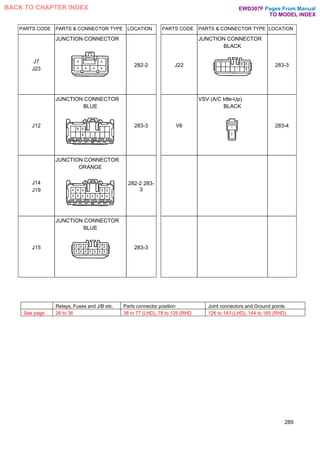
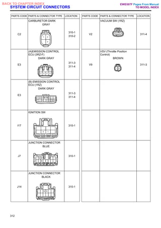
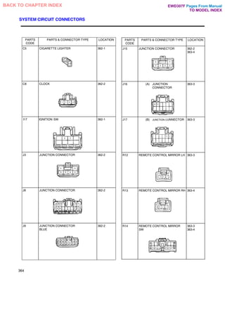
![SYSTEM CIRCUIT CONNECTORS
PARTS CODE PARTS & CONNECTOR TYPE LOCATION
A10
(A) ALTERNATOR
BLACK
171-3
A11
(B) ALTERNATOR
171-3
C9
(A) CHARGE WARNING LIGHT
[COMB. METER]
171-4
C10
(B) CHARGE WARNING LIGHT
[COMB. METER]
BLUE
171-4
117
IGNITION SW
170-1
J1
(A) JUNCTION CONNECTOR
GRAY
170-2
171-4
PARTS CODE PARTS & CONNECTOR TYPE LOCATION
J2
(B) JUNCTION CONNECTOR
GRAY
170-2 171-4
J3
(A) JUNCTION CONNECTOR
BLACK
170-2
171-4
J4
(B) JUNCTION CONNECTOR
BLACK
171-4
J9
(B) JUNCTON CONNECTOR
BLUE
171-4
J12
(A) JUNCTION CONNECTOR
BLUE
171-4
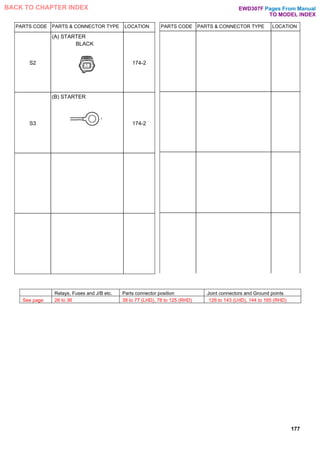
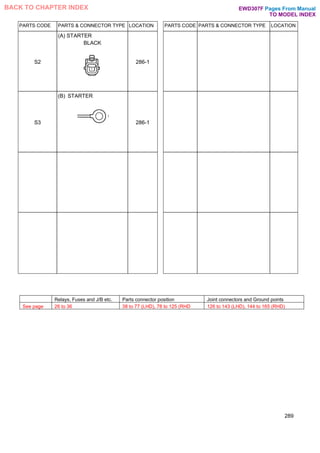
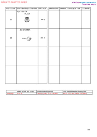
S2
(A) STARTER
BLACK
170-2
172
Pages From Manual
TO MODEL INDEX
BACK TO CHAPTER INDEX EWD307F](https://image.slidesharecdn.com/hiluxelecricalewd307f-220728231702-87b21402/85/HILUX-ELECRICAL-EWD307F-pdf-152-320.jpg)
![SYSTEM CIRCUIT CONNECTORS
PARTS CODE PARTS & CONNECTOR TYPE LOCATION
A10
(A)ALTERNATOR
BLACK
175-3
A11
(B) ALTERNATOR
175-3
C9
(A)CHARGE WARNING
LIGHT [COMB. METER]
175-4
C10
(B) CHARGE WARNING
LIGHT [COMB. METER]
BLUE
175-4
F9
FUEL HEATER
GRAY
175-3
I17
IGNITION SW
174-1
PARTS CODE PARTS & CONNECTOR TYPE LOCATION
J1
(A)JUNCTION CONNECTOR
GRAY
174-2
175-4
J2
(B)JUNCTION CONNECTOR
GRAY
174-2
175-4
J3
(A)JUNCTION CONNECTOR
BLACK
174-2
175-3
175-4
J4
(B)JUNCTION CONNECTOR
BLACK
175-4
J9
(B)JUNCTION CONNECTOR
BLUE
175-4
J12
(A)JUNCTION CONNECTOR
BLUE
175-4
176
Pages From Manual
TO MODEL INDEX
BACK TO CHAPTER INDEX EWD307F](https://image.slidesharecdn.com/hiluxelecricalewd307f-220728231702-87b21402/85/HILUX-ELECRICAL-EWD307F-pdf-156-320.jpg)
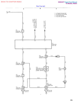
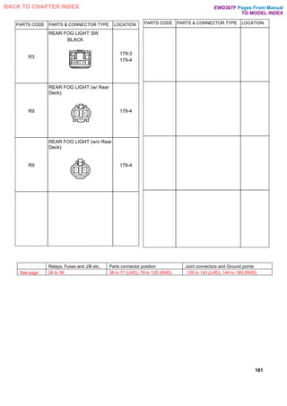
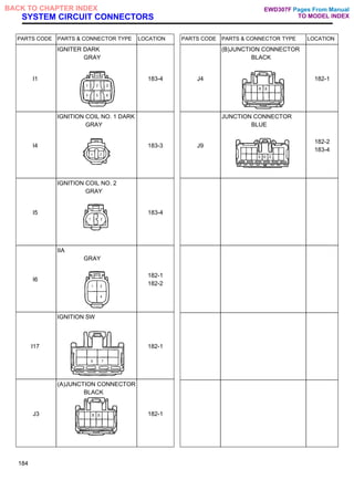
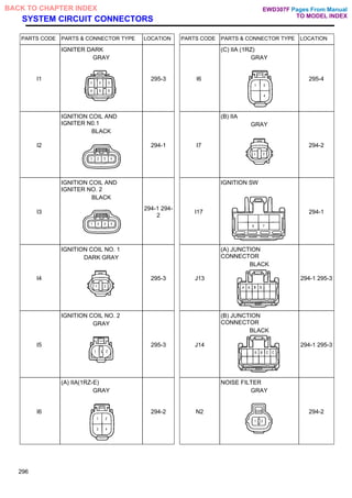
![SYSTEM CIRCUIT CONNECTORS
PARTS CODE PARTS & CONNECTOR TYPE LOCATION
C10
REAR FOG LIGHT
INDICATOR LIGHT [COMB.
METER]
BLUE
179-4
12
IGNITION COIL AND
IGNITER NO. 1
BLACK
178-1
178-2
13
IGNITION COIL AND
IGNITER NO. 2
BLACK
178-2
117
IGNITION SW
178-1
J3
(A)JUNCTION CONNECTOR
BLACK
178-2
J4
(B)JUNCTION
CONNECTOR
BLACK
178-2
PARTS CODE PARTS & CONNECTOR TYPE LOCATION
J7
JUNCTION CONNECTOR
179-3
J14
JUNCTION CONNECTOR
ORANGE
179-3
J18
JUNCTION CONNECTOR
BLUE
179-3
179-4
J19
JUNCTION CONNECTOR
ORANGE
179-3
J23
JUNCTION CONNECTOR
179-4
N2
NOISE FILTER GRAY
178-1
180
Pages From Manual
TO MODEL INDEX
BACK TO CHAPTER INDEX EWD307F](https://image.slidesharecdn.com/hiluxelecricalewd307f-220728231702-87b21402/85/HILUX-ELECRICAL-EWD307F-pdf-160-320.jpg)
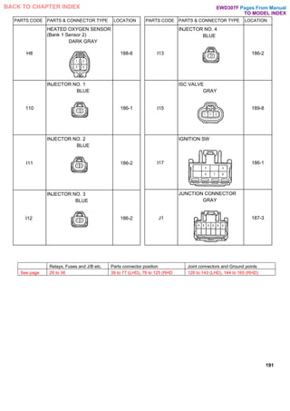
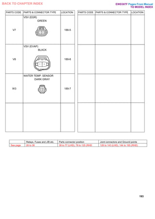
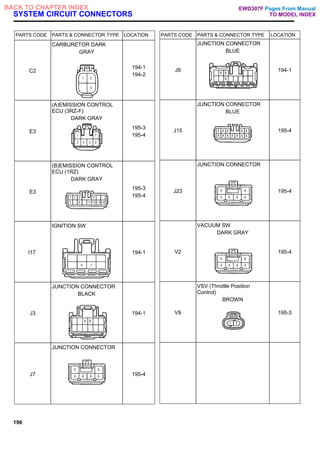
![SYSTEM CIRCUIT CONNECTORS
PARTS CODE PARTS & CONNECTOR TYPE LOCATION
A 9
AIR FLOW METER
BLACK
189-7
C1
CAMSHAFT POSITION
SENSOR
BLACK
189-7
C4
CRANKSHAFT POSITION
SENSOR
DARK GRAY
189-7
C7
CIRCUIT OPENING RELAY
187-3
C10
(B)CHECK ENGINE
WARNING LIGHT [COMB.
METER]
BLUE
187-4
C11
©CHECK ENGINE
WARNING LIGHT [COMB.
METER]
BROWN
187-4
PARTS CODE PARTS & CONNECTOR TYPE LOCATION
D10
DLC3
BLACK
187-4
E4
(A)ENGINE ECU
188-5
188-6
189-7
189-8
E5
(B) ENGINE ECU
188-5
188-6
189-7
189-8
E6
©ENGINE ECU
188-5
188-6
189-7
189-8
F12
FUEL PUMP
GRAY
187-3
H7
HEATED OXYGEN SENSOR
(Bank 1 Sensor 1)
DARK GRAY
188-6
190
Pages From Manual
TO MODEL INDEX
BACK TO CHAPTER INDEX EWD307F](https://image.slidesharecdn.com/hiluxelecricalewd307f-220728231702-87b21402/85/HILUX-ELECRICAL-EWD307F-pdf-170-320.jpg)
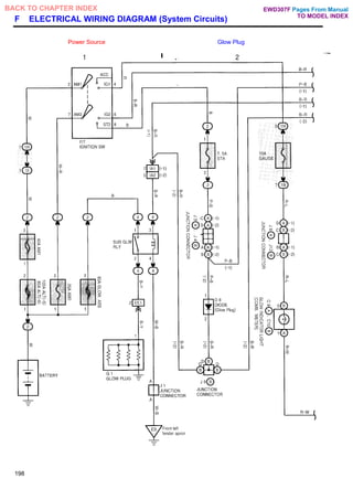
![SYSTEM CIRCUIT CONNECTORS
PARTS CODE PARTS & CONNECTOR TYPE LOCATION
C9
(A)GLOW INDICATOR LIGHT
[COMB. METER]
198-2
C10
(B)GLOW INDICATOR LIGHT
[COMB. METER]
BLUE
198-2
D8
DIODE (Glow Plug)
198-2
G1
GLOW PLUG
198-1
I9
INJECTION PUMP
GRAY
199-4
I17
IGNITION SW
198-1
PARTS CODE PARTS & CONNECTOR TYPE LOCATION
J1
JUNCTION CONNECTOR
GRAY
198-1
J3
(A) JUNCTION CONNECTOR
BLACK
198-2
J4
(B) JUNCTION CONNECTOR
BLACK
198-2
J8
(A) JUNCTION ONNECTOR
198-2
J9
(B) JUNCTION CONNECTOR
BLUE
198-2
199-4
J12
(A) JUNCTION CONNECTOR
BLUE
199-4
200
Pages From Manual
TO MODEL INDEX
BACK TO CHAPTER INDEX EWD307F](https://image.slidesharecdn.com/hiluxelecricalewd307f-220728231702-87b21402/85/HILUX-ELECRICAL-EWD307F-pdf-180-320.jpg)
![SYSTEM CIRCUIT CONNECTORS
PARTS CODE PARTS & CONNECTOR TYPE LOCATION PARTS CODE PARTS & CONNECTOR TYPE LOCATION
C10
HIGH BEAM INDICATOR
LIGHT [COMB. METER]
BLUE
202 2 J1
(A)JUNCTION CONNECTOR
GRAY
202-2
C13
COMBINATION SW
203-3 203-
4
J2
(B)JUNCTION CONNECTOR
GRAY
202-2
D3
DAYTIME RUNNING LIGHT
RELAY
BLUE
203-3 203-
4
J7
JUNCTION CONNECTOR
203-3
H5
HEADLIGHT LH
202-2 J8
JUNCTION CONNECTOR
203-3
203-4
H6
HEADLIGHT RH
202-2 J14
JUNCTION CONNECTOR
ORANGE
203-4
117
IGNITION SW
202-1 J18
JUNCTION CONNECTOR
BLUE
203-4
204
Pages From Manual
TO MODEL INDEX
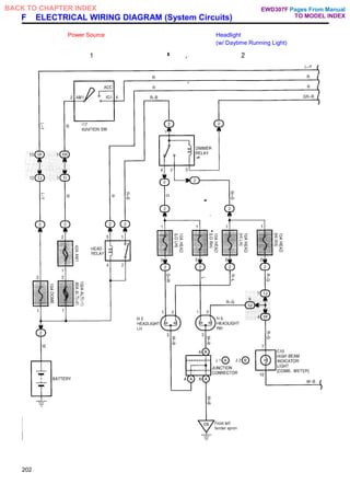
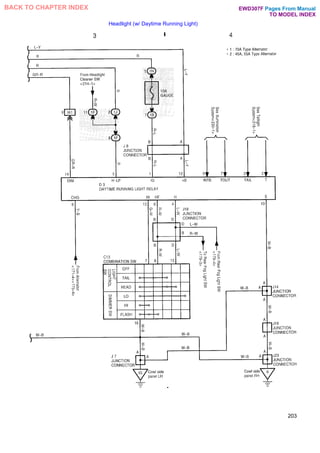
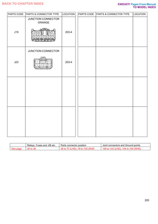
BACK TO CHAPTER INDEX EWD307F](https://image.slidesharecdn.com/hiluxelecricalewd307f-220728231702-87b21402/85/HILUX-ELECRICAL-EWD307F-pdf-184-320.jpg)
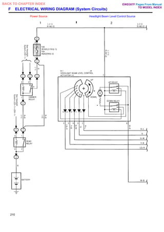
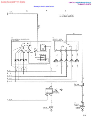
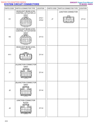
![SYSTEM CIRCUIT CONNECTORS
PARTS CODE PARTS & CONNECTOR TYPE LOCATION PARTS CODE PARTS & CONNECTOR TYPE LOCATION
C10
HIGH BEAM INDICATOR
LIGHT [COMB. METER]
BLUE
206-2 J7
JUNCTION CONNECTOR
206-1
C13
COMBINATION SW
206-1
206-2
J18
JUNCTION CONNECTOR
BLUE
206-2
H5
HEADLIGHT LH
206-2 J21
(A)JUNCTION
CONNECTOR
207-4
H6
HEADLIGHT RH
206-2 J22
(B)JUNCTION
CONNECTOR
BLACK
207-4
J3
(A)JUNCTION CONNECTOR
BLACK
206-2 J23
JUNCTION CONNECTOR
206-2
207-4
J4
(B)JUNCTION CONNECTOR
BLACK
206-2 R6
STOP LIGHT LH [REAR
COMB. LIGHT LH] (w/Rear
Deck)
207 3
208
Pages From Manual
TO MODEL INDEX
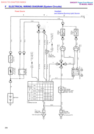
BACK TO CHAPTER INDEX EWD307F](https://image.slidesharecdn.com/hiluxelecricalewd307f-220728231702-87b21402/85/HILUX-ELECRICAL-EWD307F-pdf-188-320.jpg)
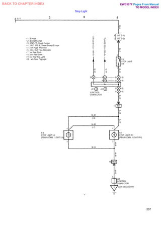
![PARTS CODE PARTS & CONNECTOR TYPE LOCATION PARTS CODE PARTS & CONNECTOR TYPE LOCATION
R6
STOP LIGHT LH [REAR
COMB. LIGHT LH] (w/o Rear
Deck)
207-3
R7
STOP LIGHT RH [REAR
COMB. LIGHT RH] (w/ Rear
Deck)
207-4
R7
STOP LIGHT RH [REAR
COMB. LIGHT RH] (w/o Rear
Deck)
207-4
S4
STOP LIGHT SW
BLACK
207-4
209
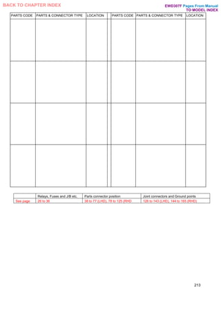
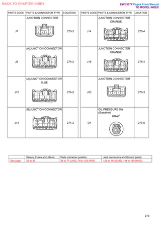
Relays, Fuses and J/B etc. Parts connector position Joint connectors and Ground points
See page 26 to 36 38 to 77 (LHD), 78 to 125 (RHD 126 to 143 (LHD), 144 to 165 (RHD)
Pages From Manual
TO MODEL INDEX
BACK TO CHAPTER INDEX EWD307F](https://image.slidesharecdn.com/hiluxelecricalewd307f-220728231702-87b21402/85/HILUX-ELECRICAL-EWD307F-pdf-189-320.jpg)
![SYSTEM CIRCUIT CONNECTORS
PARTS CODE PARTS & CONNECTOR TYPE LOCATION PARTS CODE PARTS & CONNECTOR TYPE LOCATION
C10
TURN SIGNAL INDICATOR
LIGHT [COMB. METER]
BLUE
222-2 F7
FRONT TURN SIGNAL
LIGHT LH
223-3
C13
TURN SIGNAL SW [COMB.
SW]
223-3 F8
FRONT TURN SIGNAL
LIGHT RH
223-3
F3
FRONT SIDE TURN SIGNAL
LIGHT LH
GRAY
223-3 H10
HAZARD SW
BLACK
222-1
222-2
F4
FRONT SIDE TURN SIGNAL
LIGHT RH
GRAY
223-4 I17
IGNITION SW
222-1
F5
FRONT TURN SIGNAL
LIGHT LH
223-3 J1 J2
(A), (B)JUNCTION
CONNECTOR
GRAY
223-3
F6
FRONT TURN SIGNAL
LIGHT RH
223-3 J3 J4
(A), (B)JUNCTION
CONNECTOR
BLACK
223-3
224
Pages From Manual
TO MODEL INDEX
BACK TO CHAPTER INDEX EWD307F](https://image.slidesharecdn.com/hiluxelecricalewd307f-220728231702-87b21402/85/HILUX-ELECRICAL-EWD307F-pdf-204-320.jpg)
![PARTS CODE PARTS & CONNECTOR TYPE LOCATION PARTS CODE PARTS & CONNECTOR TYPE LOCATION
J7 J23
JUNCTION CONNECTOR
222-2
223-3
223-4
R7
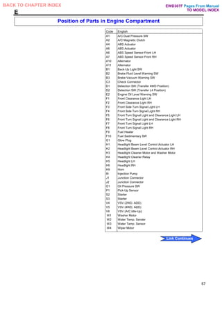
REAR TURN SIGNAL LIGHT
RH REAR COMB. LIGHT RH]
w/ Rear Deck)
223-4
J19
JUNCTION CONNECTOR
ORANGE
223-4 R7
REAR TURN SIGNAL LIGHT
RH REAR COMB. LIGHT RH]
w/o Rear Deck)
223-4
R6
REAR TURN SIGNAL LIGHT
LH [REAR COMB. LIGHT LH]
(w/ Rear Deck)
223-4
R6
REAR TURN SIGNAL LIGHT
LH [REAR COMB. LIGHT LH]
(w/o Rear Deck)
223-4
225
Relays, Fuses and J/B etc. Parts connector position Joint connectors and Ground points
See page 26 to 36 38 to 77 (LHD), 78 to 125 (RHD 126 to 143 (LHD), 144 to 165 (RHD)
Pages From Manual
TO MODEL INDEX
BACK TO CHAPTER INDEX EWD307F](https://image.slidesharecdn.com/hiluxelecricalewd307f-220728231702-87b21402/85/HILUX-ELECRICAL-EWD307F-pdf-205-320.jpg)
![SYSTEM CIRCUIT CONNECTORS
PARTS CODE PARTS & CONNECTOR TYPE LOCATION PARTS CODE PARTS & CONNECTOR TYPE LOCATION
C9
OPEN DOOR WARNING
LIGHT [COMB. METER]
227-4 D14
DOOR COURTESY SW
REAR LH
227-4
D7
DIODE (Door Courtesy)
227-3 D15
DOOR COURTESY SW
REAR RH
227-4
D11
DOOR COURTESY SW
FRONT LH (4-Door)
226-2 I16
IGNITION KEY CYLINDER
LIGHT
BLUE
226-1
D11
DOOR COURTESY SW
FRONT LH (2-Door)
226-2 I17
IGNITION SW
226-1
D12
DOOR COURTESY SW
FRONT RH (4-Door)
227-3 I18
(A) INTEGRATION RELAY
226-1 226-
2
D12
DOOR COURTESY SW
FRONT RH (2-Door)
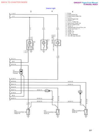
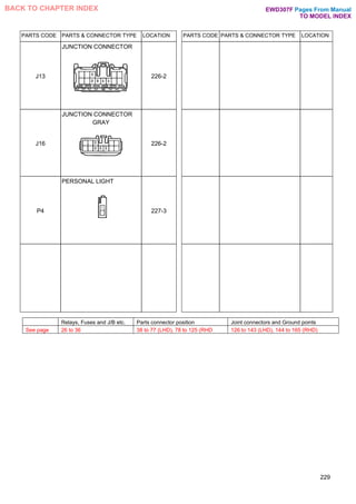
227-3 I20
INTERIOR LIGHT
227-3
228
Pages From Manual
TO MODEL INDEX
BACK TO CHAPTER INDEX EWD307F](https://image.slidesharecdn.com/hiluxelecricalewd307f-220728231702-87b21402/85/HILUX-ELECRICAL-EWD307F-pdf-208-320.jpg)
![SYSTEM CIRCUIT CONNECTORS
PARTS CODE PARTS & CONNECTOR TYPE LOCATION PARTS CODE PARTS & CONNECTOR TYPE LOCATION
A14
A/CSW
BLACK
230-2 C11
©METER ILLUMINATION
[COMB. METER]
BROWN
230-2
A26
ASHTRAY ILLUMINATION
BLACK
231-3 D3
DAYTIME RUNNING LIGHT
RELAY
BLUE
230-1
B6
(A) BLOWER SW (Europe,
G. C. C. )
231-3 D5
DIFF. LOCKSW
BLACK
231-3
B6
(B) BLOWER SW (General)
BLACK
231-3 G2
GLOVE BOX LIGHT
BLACK
231-4
C6
CIGARETTE LIGHTER
ILLUMINATION
GRAY
231-3 H10
HAZARD SW
BLACK
230-2
C9
(A) METER ILLUMINATION
[COMB. METER]
230-2 J1 J2
(A), (B)JUNCTION
CONNECTOR
GRAY
230-1
232
Pages From Manual
TO MODEL INDEX
BACK TO CHAPTER INDEX EWD307F](https://image.slidesharecdn.com/hiluxelecricalewd307f-220728231702-87b21402/85/HILUX-ELECRICAL-EWD307F-pdf-212-320.jpg)
![SYSTEM CIRCUIT CONNECTORS
PARTS CODE PARTS & CONNECTOR TYPE LOCATION PARTS CODE PARTS & CONNECTOR TYPE LOCATION
D16
DOOR KEY LOCK AND
UNLOCK SW
GRAY
235-4 I19
(B) INTEGRATION RELAY
GREEN
234-1
234-2
235-3
235-4
D17
(A) DOOR LOCK CONTROL
SW
235-3 J5
(A) JUNCTION
CONNECTOR
234-2
235-3
235-4
D18
DOOR LOCK MOTOR
FRONT LH
BLACK
234-2 J6
(B) JUNCTION
CONNECTOR
234-2
235-3
235-4
D19
DOOR LOCK MOTOR
FRONT RH
BLACK
234-1 J7
JUNCTION CONNECTOR
235-4
D20
DOOR LOCK MOTOR REAR
LH
BLACK
234-2 P9
(B)DOOR LOCK CONTROL
SW [POWER WINDOW
MASTER SW] (4-Door)
235-3
D21
DOOR LOCK MOTOR REAR
RH
BLACK
235-3 P9
(C)DOOR LOCK CONTROL
SW [POWER WINDOW
MASTER SW] (2-Door)
235-3
236
Pages From Manual
TO MODEL INDEX
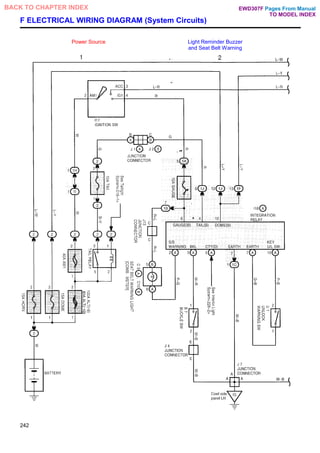
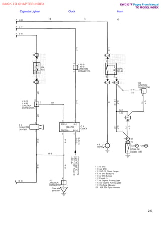
BACK TO CHAPTER INDEX EWD307F](https://image.slidesharecdn.com/hiluxelecricalewd307f-220728231702-87b21402/85/HILUX-ELECRICAL-EWD307F-pdf-216-320.jpg)
![SYSTEM CIRCUIT CONNECTORS
PARTS CODE PARTS & CONNECTOR TYPE LOCATION PARTS CODE PARTS & CONNECTOR TYPE LOCATION
B7
BUCKLE SW
242-2 C14
(B) HORN SW [COMB. SW]
(W/SRS)
243-4
C5
CIGARETTE LIGHTER
243-3 H9
HORN
BLACK
243-4
C8
CLOCK
243-3 I17
IGNITION SW
242-1
C9
(A) SEAT BELT WARNING
LIGHT [COMB. METER]
242 1 I18
(A) INTEGRATION RELAY
242-2
C10
(B) SEAT BELT WARNING
LIGHT [COMB. METER]
BLUE
242-1 J1
(A) JUNCTION
CONNECTOR
GRAY
242-1
C12
(A) HORN SW [COMB. SW]
(W/O SRS)
BLACK
243-4 J2
(B) JUNCTION
CONNECTOR
GRAY
242-1
244
Pages From Manual
TO MODEL INDEX
BACK TO CHAPTER INDEX EWD307F](https://image.slidesharecdn.com/hiluxelecricalewd307f-220728231702-87b21402/85/HILUX-ELECRICAL-EWD307F-pdf-224-320.jpg)
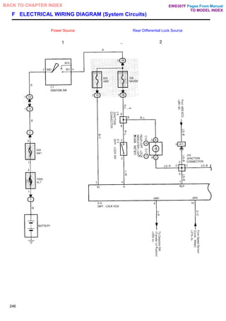
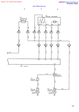
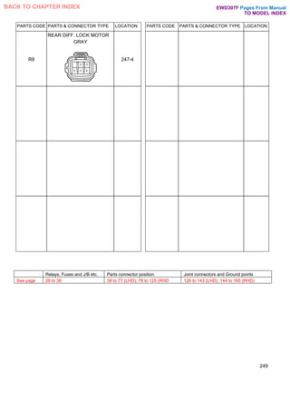
![SYSTEM CIRCUIT CONNECTORS
PARTS CODE PARTS & CONNECTOR TYPE LOCATION PARTS CODE PARTS & CONNECTOR TYPE LOCATION
C10
(B)REARDIFF. LOCK
INDICATOR LIGHT [COMB.
METER]
BLUE
246-2
JUNCTION CONNECTOR
247-3
C11
(C)REARDIFF. LOCK
INDICATOR LIGHT [COMB.
METER]
BROWN
246-2 J8
JUNCTION CONNECTOR
246-2
D4
DIFF. LOCK ECU
246-1 246-
2 247-3
247-4
J14
JUNCTION CONNECTOR
ORANGE
247 3
D5
DIFF. LOCKSW
BLACK
246-2 J16
JUNCTION CONNECTOR
GRAY
246-2
D13
DETECTION SW (Rear Diff.
Lock)
GRAY
247-3 J19
JUNCTION CONNECTOR
ORANGE
247-4
I17
IGNITION SW
246-1 J23
JUNCTION CONNECTOR
247-4
248
Pages From Manual
TO MODEL INDEX
BACK TO CHAPTER INDEX
J7
EWD307F](https://image.slidesharecdn.com/hiluxelecricalewd307f-220728231702-87b21402/85/HILUX-ELECRICAL-EWD307F-pdf-228-320.jpg)
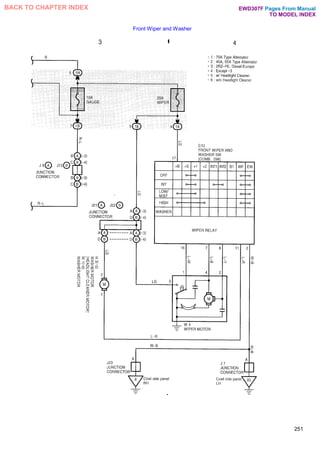
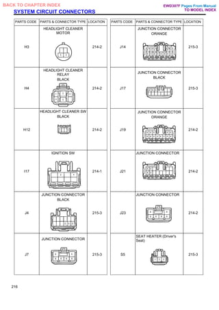
![SYSTEM CIRCUIT CONNECTORS
PARTS CODE PARTS & CONNECTOR TYPE LOCATION PARTS CODE PARTS & CONNECTOR TYPE LOCATION
C12
FRONT WIPER AND
WASHER SW [COMB. SW]
BLACK
251-4 J14
JUNCTION CONNECTOR
ORANGE
250-2
H3
WASHER MOTOR
[HEADLIGHT CLEANER
MOTOR]
251-3 J15
JUNCTION CONNECTOR
BLUE
250-2
I17
IGNITION SW
250-1 J21
(A) JUNCTION
CONNECTOR
251-3
J7
JUNCTION CONNECTOR
250-2 251-
4
J22
(DJUNCTION CONNECTOR
BLACK
251-3
J8
(A)JUNCTION CONNECTOR
251-3 J23
JUNCTION CONNECTOR
251-3
J13
(B) JUNCTION CONNECTOR
251-3 R4
REAR WINDOW
DEFOGGER SW
BLACK
250-2
252
Pages From Manual
TO MODEL INDEX
BACK TO CHAPTER INDEX EWD307F](https://image.slidesharecdn.com/hiluxelecricalewd307f-220728231702-87b21402/85/HILUX-ELECRICAL-EWD307F-pdf-232-320.jpg)
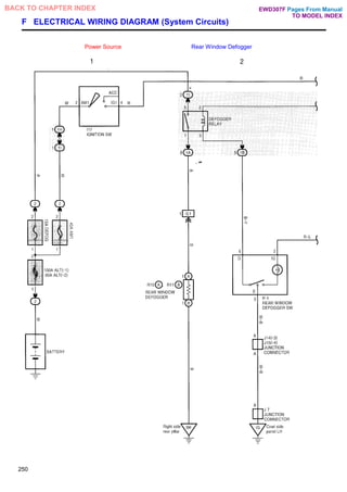
![SYSTEM CIRCUIT CONNECTORS
PARTS CODE PARTS & CONNECTOR TYPE LOCATION PARTS CODE PARTS & CONNECTOR TYPE LOCATION
A 8
ADD INDICATOR SW
GRAY
254-2 I17
IGNITION SW
254-1
A20
ADD CONTROL RELAY
254-2 J1 J2
(A), (B)JUNCTION
CONNECTOR
GRAY
254-1
C10
(B)4WD INDICATOR LIGHT
[COMB. METER]
BLUE
255-3 J3 J4
(A), (B)JUNCTION
CONNECTOR
BLACK
254-2
C11
(C)4WD INDICATOR LIGHT
[COMB. METER]
BROWN
255-3 J7 J23
JUNCTION CONNECTOR
255-3
255-4
D1
DETECTION SW (Transfer
4WD Position)
GRAY
255-3 J8
(A)JUNCTION
CONNECTOR
255-3
D2
DETECTION SW (Transfer
L4 Position)
BLUE
255-4 J13
(B) JUNCTION
CONNECTOR
255-3
256
Pages From Manual
TO MODEL INDEX
BACK TO CHAPTER INDEX EWD307F](https://image.slidesharecdn.com/hiluxelecricalewd307f-220728231702-87b21402/85/HILUX-ELECRICAL-EWD307F-pdf-236-320.jpg)
![SYSTEM CIRCUIT CONNECTORS
PARTS CODE PARTS & CONNECTOR TYPE LOCATION
A 4
(A)ABS ACTUATOR
GRAY
259-3
259-4
A 5
(DABS ACTUATOR
BLACK
259-3
259-4
A 6
ABS SPEED SENSOR
FRONT LH
GRAY
260-5
A 7
ABS SPEED SENSOR
FRONT RH
GRAY
260-5
A17
ABS DECELERATION
SENSOR
BLACK
261-7
A18
(A)ABS ECU
259-3
259-4
260-5
260-6
261-7
261-8
262
PARTS CODE PARTS & CONNECTOR TYPE LOCATION
A19
(C) ABS ECU
259-3
259-4
260-5
260-6
261-7
261-8
A28
ABS SPEED SENSOR
REAR LH
GRAY
261-7
A29 *
ABS SPEED SENSOR
REAR RH
GRAY
261-8
C3
CHECK CONNECTOR
(2RZ-FE, 2L-T)
BLACK
259-3
259-4
C3
CHECK CONNECTOR
(EXCEPT 2RZ-FE 2L-T)
BLACK
259-3
259-4
C10
(B)ABS WARNING LIGHT
[COMB. METER]
BLUE
260-5
Pages From Manual
TO MODEL INDEX
BACK TO CHAPTER INDEX EWD307F](https://image.slidesharecdn.com/hiluxelecricalewd307f-220728231702-87b21402/85/HILUX-ELECRICAL-EWD307F-pdf-242-320.jpg)
![PARTS CODE PARTS & CONNECTOR TYPE LOCATION PARTS CODE PARTS & CONNECTOR TYPE LOCATION
C11
(C) ABS WARNING LIGHT
[COMB. METER]
BROWN
260-5 J8
(A) JUNCTION
CONNECTOR
260-5
I17
IGNITION SW
258-1 J9
(B) JUNCTION
CONNECTOR
BLUE
258-2
J3
JUNCTION CONNECTOR
BLACK
258-2 J12
(A)JUNCTION
CONNECTOR
BLUE
258-2
J7
JUNCTION CONNECTOR
260-6 J13
(B) JUNCTION
CONNECTOR
260-5
263
Relays, Fuses and J/B etc. Parts connector position Joint connectors and Ground points
See page 26 to 36 38 to 77 (LHD), 78 to 125 (RHD 126 to 143 (LHD), 144 to 165 (RHD)
Pages From Manual
TO MODEL INDEX
BACK TO CHAPTER INDEX EWD307F](https://image.slidesharecdn.com/hiluxelecricalewd307f-220728231702-87b21402/85/HILUX-ELECRICAL-EWD307F-pdf-243-320.jpg)
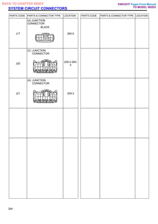
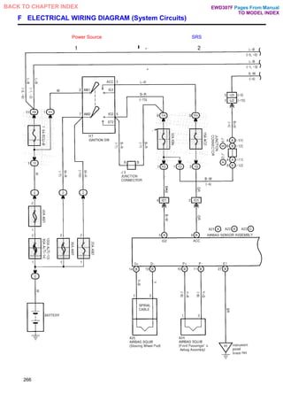
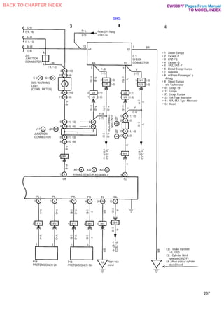
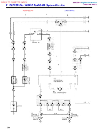
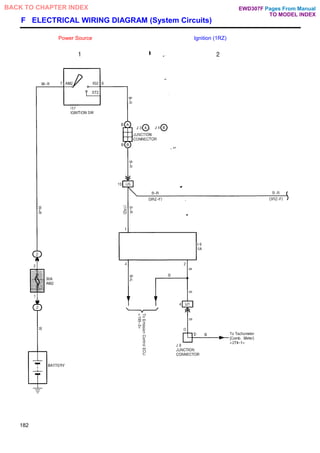
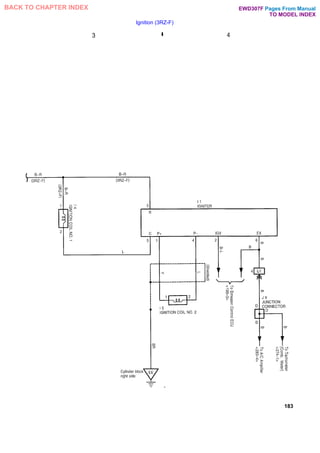
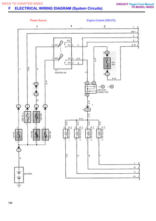
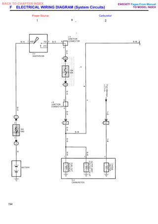
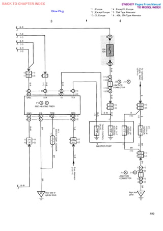
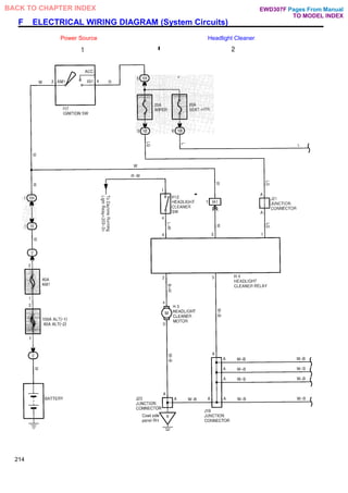
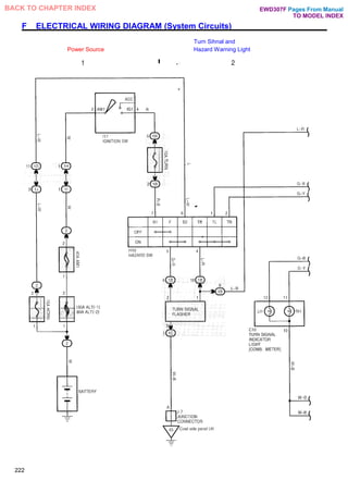
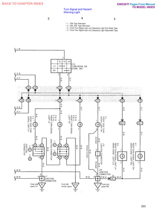
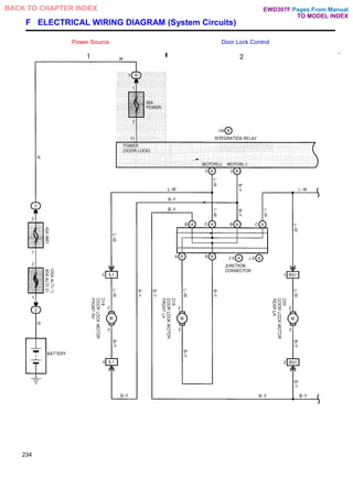
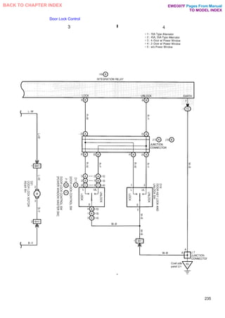
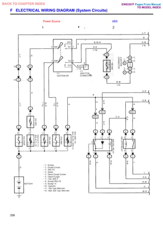
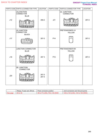
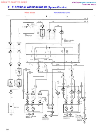
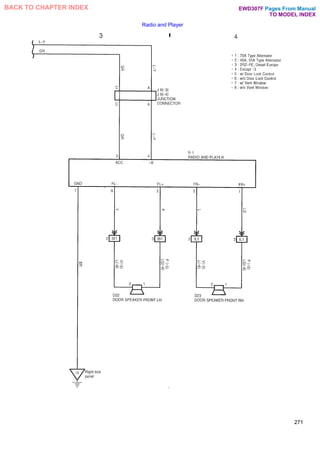
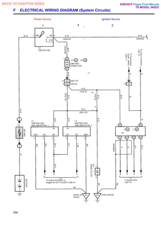
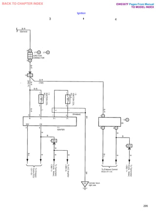
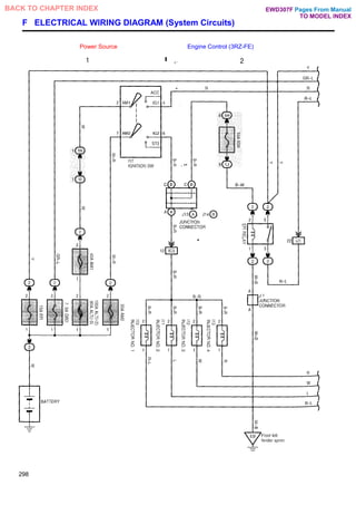
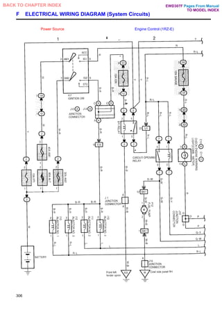
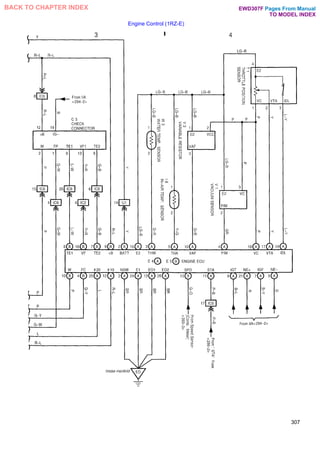
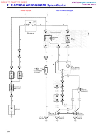
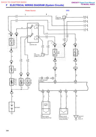
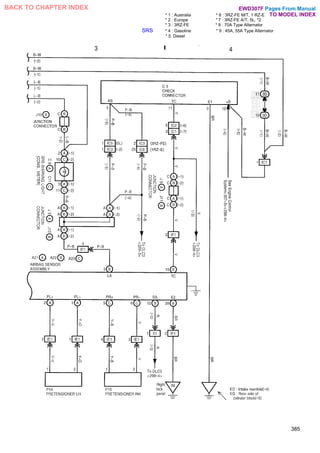
![F ELECTRICAL WIRING DIAGRAM (System Circuits)
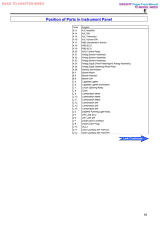
PARTS CODE PARTS & CONNECTOR TYPE LOCATION PARTS CODE PARTS & CONNECTOR TYPE LOCATION
A21
(A)AIRBAG SENSOR
ASSEMBLY
YELLOW
266-2
267-3
267-4
C3
CHECK CONNECTOR
(Except 2RZ-FE 2L-T)
BLACK
267-3
267-4
A22
(B) AIRBAG SENSOR
ASSEMBLY
YELLOW
266-2
267-3
267-4
C9
(A)SRS WARNING LIGHT
[COMB. METER]
267-3
A23
(C)AIRBAG SENSOR
ASSEMBLY
YELLOW
266-2
267-3
267-4
C11
(C)SRS WARNING LIGHT
[COMB. METER]
BROWN
267-3
A24
AIRBAG SQUIB (Front
Passenger's Airbag
Assembly)
YELLOW
266-2 I17
IGNITION SW
266-1
A25
AIRBAG SQUIB (Steering
Wheel Pad)
YELLOW
266-1
266-2
J3
JUNCTION CONNECTOR
BLACK
266-1
C3
CHECK CONNECTOR (2RZ-
FE, 2L-T)
BLACK
267-3
267-4
J9
(B) JUNCTION CONNECTOR
BLUE
266-2
268
Pages From Manual
TO MODEL INDEX
BACK TO CHAPTER INDEX EWD307F](https://image.slidesharecdn.com/hiluxelecricalewd307f-220728231702-87b21402/85/HILUX-ELECRICAL-EWD307F-pdf-248-320.jpg)
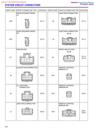

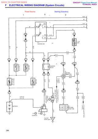
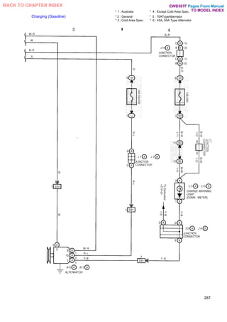
![SYSTEM CIRCUIT CONNECTORS
PARTS CODE PARTS & CONNECTOR TYPE LOCATION PARTS CODE PARTS & CONNECTOR TYPE LOCATION
A10
(A) ALTERNATOR
BLACK
287-3 J2
(B)JUNCTION CONNECTOR
GRAY
287-4
A11
(B)ALTERNATOR
287-3 J7
JUNCTION CONNECTOR
BLUE
287-4
C9
(A)CHARGE WARNING
LIGHT [COMB. METER]
287-4 J12
JUNCTION CONNECTOR
BLUE
286-2
C10
(B)CHARGE WARNING
LIGHT [COMB. METER]
BLUE
287-4 J13
(A) JUNCTION
CONNECTOR
BLACK
287-4
I17
IGNITION SW
286-1 J14
(B) JUNCTION
CONNECTOR
BLACK
287-4
J1
(A) JUNCTION
CONNECTOR
GRAY
286-2
287-4
N1
NEUTRAL START SW
GRAY
286-2
288
Pages From Manual
TO MODEL INDEX
BACK TO CHAPTER INDEX EWD307F](https://image.slidesharecdn.com/hiluxelecricalewd307f-220728231702-87b21402/85/HILUX-ELECRICAL-EWD307F-pdf-268-320.jpg)
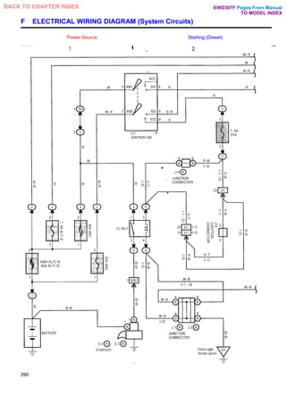
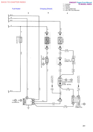
![SYSTEM CIRCUIT CONNECTORS
PARTS CODE PARTS & CONNECTOR TYPE LOCATION PARTS CODE PARTS & CONNECTOR TYPE LOCATION
A10
(A) ALTERNATOR
(B) BLACK
291-3 J1
(A) JUNCTION CONNECTOR
GRAY
290-2
291-3
A11
(B)ALTERNATOR
291-3 J2
(B) JUNCTION CONNECTOR
GRAY
290-2
291-3
C9
(A)CHARGE WARNING
LIGHT [COMB. METER]
291-4 J7
JUNCTION CONNECTOR
BLUE
291-4
C10
(B)CHARGE WARNING
LIGHT [COMB. METER]
BLUE
291-4 J12
JUNCTION CONNECTOR
BLUE
290-2
F9
FUEL HEATER
GRAY
291-3 J13
(A)JUNCTION CONNECTOR
BLACK
291-4
117
IGNITION SW
290-2 J14
(B) JUNCTION CONNECTOR
BLACK
290-2
291-4
292
Pages From Manual
TO MODEL INDEX
BACK TO CHAPTER INDEX EWD307F](https://image.slidesharecdn.com/hiluxelecricalewd307f-220728231702-87b21402/85/HILUX-ELECRICAL-EWD307F-pdf-272-320.jpg)
![SYSTEM CIRCUIT CONNECTORS
PARTS CODE PARTS & CONNECTOR TYPE LOCATION PARTS CODE PARTS & CONNECTOR TYPE LOCATION
A 9
AIR FLOW METER
BLACK
300-5 D10
DLC3
BLACK
299-3
299-4
C1
CAMSHAFT POSITION
SENSOR
BLACK
301-7 E4
(A) ENGINE ECU (M/T) OR
ENGINE AND ECT ECU
(A/T)
300-5
300-6
301-7
301-8
C3
CHECK CONNECTOR
BLACK
299-4 E5
(B) ENGINE ECU (M/T) OR
ENGINE AND ECT ECU
(A/T)
300-5
300-6
301-7
301-8
C4
CRANKSHAFT POSITION
SENSOR
DARK GRAY
301-7 E6
(C)ENGINE ECU (M/T) OR
ENGINE AND ECT ECU
(A/T)
300-5
300-6
301-7
301-8
C10
(B) CHECK ENGINE
WARNING LIGHT [COMB.
METER]
BLUE
299-3 F12
FUEL PUMP GRAY (III
299-3
C11
(C) CHECK ENGINE
WARNING LIGHT [COMB.
METER]
BROWN
299-3 I10
INJECTOR NO. 1
BLUE
298-1
302
Pages From Manual
TO MODEL INDEX
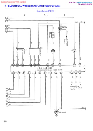
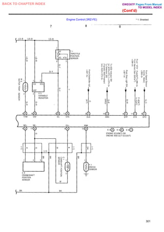
BACK TO CHAPTER INDEX EWD307F](https://image.slidesharecdn.com/hiluxelecricalewd307f-220728231702-87b21402/85/HILUX-ELECRICAL-EWD307F-pdf-282-320.jpg)
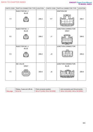
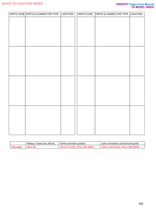
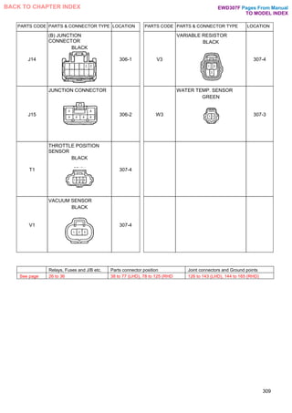
![SYSTEM CIRCUIT CONNECTORS
PARTS CODE PARTS & CONNECTOR TYPE LOCATION PARTS CODE PARTS & CONNECTOR TYPE LOCATION
C3
CHECK CONNECTOR
BLACK
307-3 I8
IN-AIR TEMP. SENSOR
BLACK
307-4
C10
(B) CHECK ENGINE
WARNING LIGHT [COMB.
METER]
BLUE
306-2
I10
I11
I12
I13
INJECTOR NO. 1, NO. 2,
NO. 3, NO. 4
GRAY
306-1
C11
(C) CHECK ENGINE
WARNING LIGHT [COMB.
METER)
BROWN
306-2 I17
IGNITION SW
306-1
E4
(A) ENGINE ECU
307-3 307-
4
J1
JUNCTION CONNECTOR
GRAY
306-2
E5
(B) ENGINE ECU
307-3 307-
4
J12
JUNCTION CONNECTOR
BLUE
306-2
F12
FUEL PUMP
GRAY
306-2 J13
(A) JUNCTION
CONNECTOR
BLACK
306-1
308
Pages From Manual
TO MODEL INDEX
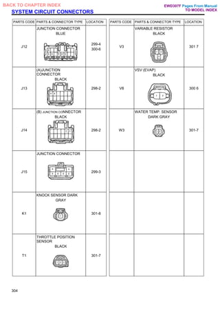
BACK TO CHAPTER INDEX EWD307F](https://image.slidesharecdn.com/hiluxelecricalewd307f-220728231702-87b21402/85/HILUX-ELECRICAL-EWD307F-pdf-288-320.jpg)
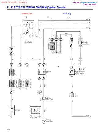
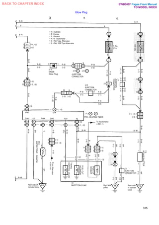
![SYSTEM CIRCUIT CONNECTORS
PARTS CODE PARTS & CONNECTOR TYPE LOCATION PARTS CODE PARTS & CONNECTOR TYPE LOCATION
C9
(A) GLOW INDICATOR
LIGHT [COMB. METER]
314-2 I17
IGNITION SW
314-1
C10
(B) GLOW INDICATOR
LIGHT [COMB. METER]
BLUE
314-2 J1
JUNCTION CONNECTOR
GRAY
314-1
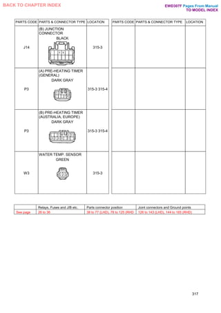
D8
DIODE (Glow Plug)
315-3 J6
JUNCTION CONNECTOR
314-2
G1
GLOW PLUG
314-1 J7
JUNCTION CONNECTOR
BLUE
315-4
I9
INJECTION PUMP
GRAY
315-3 315-
4
J12
JUNCTION CONNECTOR
BLUE
315-4
I14
INTAKE SHUTTER
BROWN
315-4 J13
(A) JUNCTION
CONNECTOR
BLACK
315-3
316
Pages From Manual
TO MODEL INDEX
BACK TO CHAPTER INDEX EWD307F](https://image.slidesharecdn.com/hiluxelecricalewd307f-220728231702-87b21402/85/HILUX-ELECRICAL-EWD307F-pdf-296-320.jpg)
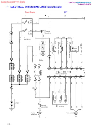
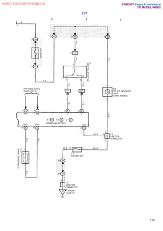
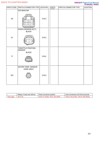
![SYSTEM CIRCUIT CONNECTORS
PARTS CODE PARTS & CONNECTOR TYPE LOCATION PARTS CODE PARTS & CONNECTOR TYPE LOCATION
A3
A/T FLUID TEMP. SW
GRAY
318-2 I17
IGNITION SW
318-1
C10
O/D OFF INDICATOR LIGHT
[COMB. METER]
BLUE
319-4 J1
JUNCTION CONNECTOR
GRAY
318-1
E1
ECT SOLENOID
BLACK
318-2 J3
JUNCTION CONNECTOR
319-3
E4
(A) ENGINEANDECTECU
318-2
319-3
J4
JUNCTION CONNECTOR
BLUE
319-4
E5
(B) ENGINE AND ECT ECU
318-2
319-3
J14
JUNCTION CONNECTOR
BLACK
318-1
E6
(C) ENGINE AND ECT ECU
318-2
319-3
N1
NEUTRAL START SW
GRAY
319-3
320
Pages From Manual
TO MODEL INDEX
BACK TO CHAPTER INDEX EWD307F](https://image.slidesharecdn.com/hiluxelecricalewd307f-220728231702-87b21402/85/HILUX-ELECRICAL-EWD307F-pdf-300-320.jpg)
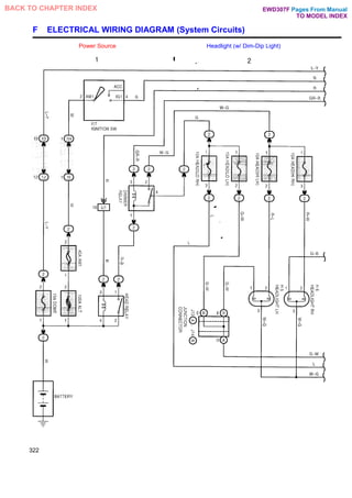
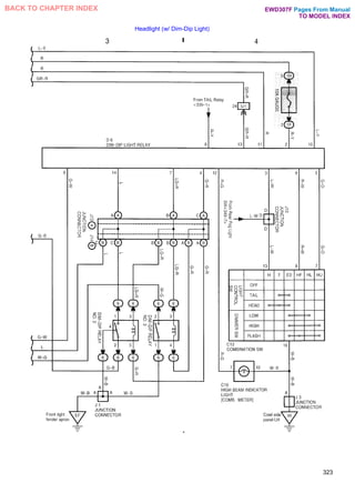
![SYSTEM CIRCUIT CONNECTORS
PARTS CODE PARTS & CONNECTOR TYPE LOCATION PARTS CODE PARTS & CONNECTOR TYPE LOCATION
C10
HIGH BEAM INDICATOR
LIGHT [COMB. METER]
BLUE
323-4 J1
JUNCTION CONNECTOR
GRAY
323-3
C13
COMBINATION SW
323-4 J3
JUNCTION CONNECTOR
323-4
D6
DIM-DIP LIGHT RELAY
323-3 323-4 J10
JUNCTION CONNECTOR
BLACK
323-4
H5
HEADLIGHT LH
322-2 J13
(A) JUNCTION
CONNECTOR
BLACK
322-2
323-3
323-4
H6
HEADLIGHT RH
322 2 J14
(B) JUNCTION
CONNECTOR
BLACK
322-2
323-3
323-4
I17
IGNITION SW
322-1
324
Pages From Manual
TO MODEL INDEX
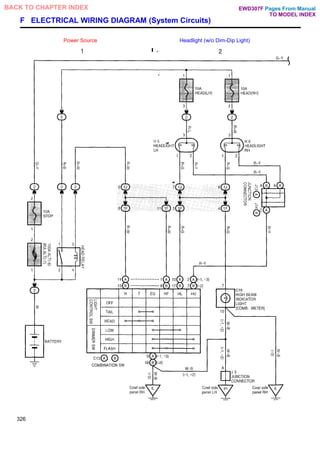
BACK TO CHAPTER INDEX EWD307F](https://image.slidesharecdn.com/hiluxelecricalewd307f-220728231702-87b21402/85/HILUX-ELECRICAL-EWD307F-pdf-304-320.jpg)
![SYSTEM CIRCUIT CONNECTORS
PARTS CODE PARTS & CONNECTOR TYPE LOCATION PARTS CODE PARTS & CONNECTOR TYPE LOCATION
C10
HIGH BEAM INDICATOR
LIGHT [COMB. METER]
BLUE
326-2 J11
JUNCTION CONNECTOR
BLACK
327-4
C13
(A)COMBINATION SW
(Australia, General)
326-1
326-2
J13
(A) JUNCTION
CONNECTOR
BLACK
326-2
327-4
C13
(B) COMBINATION SW
(Europe)
326-1
326-2
J14
(B) JUNCTION
CONNECTOR
BLACK
326-2
H5
HEADLIGHT LH
326-2 J15
JUNCTION CONNECTOR
327-3
H6
HEADLIGHT RH
326-2 R6
STOP LIGHT LH [REAR
COMB. LIGHT LH] (W/
REAR DECK, MALTA)
327-3
J3
JUNCTION CONNECTOR
326-2 R6
STOP LIGHT LH [REAR
COMB. LIGHT LH]
(EXCEPT W/ REAR DECK,
MALTA)
327-3
328
Pages From Manual
TO MODEL INDEX
BACK TO CHAPTER INDEX EWD307F](https://image.slidesharecdn.com/hiluxelecricalewd307f-220728231702-87b21402/85/HILUX-ELECRICAL-EWD307F-pdf-308-320.jpg)
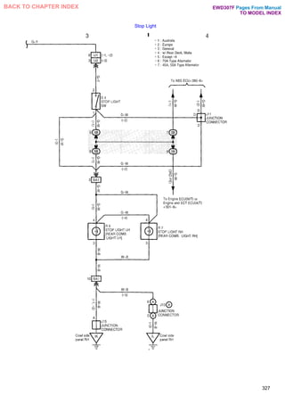
![PARTS CODE PARTS & CONNECTOR TYPE LOCATION PARTS CODE PARTS & CONNECTOR TYPE LOCATION
R7
STOP LIGHT RH [REAR COMB.
LIGHT RH] (w/ Rear Deck, Malta)
327-3
R7
STOP LIGHT RH [REAR COMB.
LIGHT RH] (Except w/ Rear Deck,
Malta)
327-3
S4
STOP LIGHT SW
BLACK
327-3
329
Relays, Fuses and J/B etc. Parts connector position Joint connectors and Ground points
See page 26 to 36 38 to 77 (LHD), 78 to 125 (RHD 126 to 143 (LHD), 144 to 165 (RHD)
Pages From Manual
TO MODEL INDEX
BACK TO CHAPTER INDEX EWD307F](https://image.slidesharecdn.com/hiluxelecricalewd307f-220728231702-87b21402/85/HILUX-ELECRICAL-EWD307F-pdf-309-320.jpg)
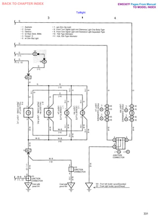
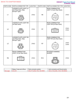
![PARTS CODE PARTS & CONNECTOR TYPE LOCATION PARTS CODE PARTS & CONNECTOR TYPE LOCATION
L1
LICENSE PLATE LIGHT LH
(w/ Rear Deck)
331-3 R6
TAILLIGHT LH REAR
COMB. LIGHT LH] w/ Rear
Deck, Malta)
331-3
L1
LICENSE PLATE LIGHT LH
(w/o Rear Deck)
331-3 R6
TAILLIGHT LH REAR
COMB. LIGHT LH] Except w/
Rear Deck, Malta)
331-3
L2
LICENSE PLATE LIGHT
RH (w/ Rear Deck)
331-3 R7
TAILLIGHT RH REAR
COMB. LIGHT RH] w/ Rear
Deck, Malta)
331-3
L2
LICENSE PLATE LIGHT
RH (w/o Rear Deck)
331-3 R7
TAILLIGHT RH REAR
COMB. LIGHT RH] Except
w/ Rear Deck, Malta)
331-3
333
Relays, Fuses and J/B etc. Parts connector position Joint connectors and Ground points
See page 26 to 36 38 to 77 (LHD), 78 to 125 (RHD 126 to 143 (LHD), 144 to 165 (RHD)
Pages From Manual
TO MODEL INDEX
BACK TO CHAPTER INDEX EWD307F](https://image.slidesharecdn.com/hiluxelecricalewd307f-220728231702-87b21402/85/HILUX-ELECRICAL-EWD307F-pdf-313-320.jpg)
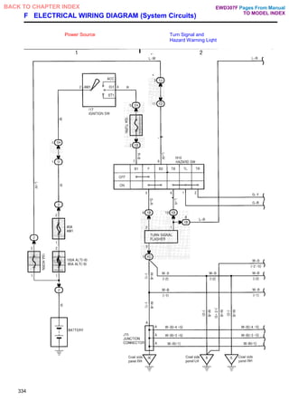
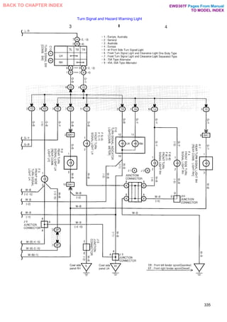
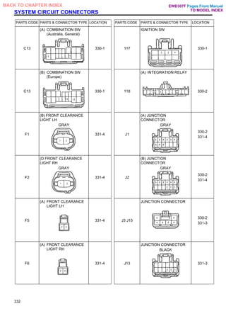
![SYSTEM CIRCUIT CONNECTORS
PARTS CODE PARTS & CONNECTOR TYPE LOCATION PARTS CODE PARTS & CONNECTOR TYPE LOCATION
C10
TURN SIGNAL INDICATOR
LIGHT [COMB. METER]
BLUE
335-3
335-4
F6
FRONT TURN SIGNAL
LIGHT RH
335-4
C13
(A)TURN SIGNAL SW
COMB. SW] Australia,
General)
335-3 F7
FRONT TURN SIGNAL
LIGHT LH
335-3
C13
(B)TURN SIGNAL SW
COMB. SW] Europe)
335-3 F8
FRONT TURN SIGNAL
LIGHT RH
335-4
F3
FRONT SIDE TURN SIGNAL
LIGHT LH
GRAY
335-3 H10
HAZARD SW
BLACK
334-1
334-2
F4
FRONT SIDE TURN SIGNAL
LIGHT RH
GRAY
335-4 117
IGNITION SW
334-1
F5
FRONT TURN SIGNAL
LIGHT LH
335-3 J1 J2
(A), (B) JUNCTION
CONNECTOR
GRAY
335-4
336
Pages From Manual
TO MODEL INDEX
BACK TO CHAPTER INDEX EWD307F](https://image.slidesharecdn.com/hiluxelecricalewd307f-220728231702-87b21402/85/HILUX-ELECRICAL-EWD307F-pdf-316-320.jpg)
![PARTS CODE PARTS & CONNECTOR TYPE LOCATION PARTS CODE PARTS & CONNECTOR TYPE LOCATION
J3
J15
JUNCTION CONNECTOR
334-2
335-4
R6
REAR TURN SIGNAL LIGHT
LH REAR COMB. LIGHT LH]
w/ Rear Deck, Malta)
335-3
J9
JUNCTION CONNECTOR
BLUE
335-3 R6
REAR TURN SIGNAL LIGHT
LH REAR COMB. LIGHT LH]
Except w/ Rear Deck, Malta)
335-3
J13
JUNCTION CONNECTOR
BLACK
335-3 R7
REAR TURN SIGNAL LIGHT
RH REAR COMB. LIGHT
RH] w/ Rear Deck, Malta)
335-4
J14
JUNCTION CONNECTOR
BLACK
335-4 R7
REAR TURN SIGNAL LIGHT
RH REAR COMB. LIGHT
RH] Except w/ Rear Deck,
Malta)
335-4
337
Relays, Fuses and J/B etc. Parts connector position Joint connectors and Ground points
See page 26 to 36 38 to 77 (LHD), 78 to 125 (RHD 126 to 143 (LHD), 144 to 165 (RHD)
Pages From Manual
TO MODEL INDEX
BACK TO CHAPTER INDEX EWD307F](https://image.slidesharecdn.com/hiluxelecricalewd307f-220728231702-87b21402/85/HILUX-ELECRICAL-EWD307F-pdf-317-320.jpg)
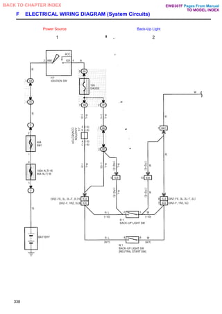
![SYSTEM CIRCUIT CONNECTORS
PARTS CODE PARTS & CONNECTOR TYPE LOCATION PARTS CODE PARTS & CONNECTOR TYPE LOCATION
B1
BACK-UP LIGHT SW
GRAY
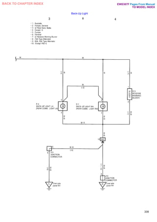
338-2 R6
BACK-UP LIGHT LH [REAR
COMB. LIGHT LH] (w/ Rear
Deck, Malta)
339-3
I17
IGNITION SW
338-1 R6
BACK-UP LIGHT LH REAR
COMB. LIGHT LH] Except w/
Rear Deck, Malta)
339-3
J6
JUNCTION CONNECTOR
338-1 R7
BACK-UP LIGHT RH REAR
COMB. LIGHT RH] w/ Rear
Deck, Malta)
339-4
J13
JUNCTION CONNECTOR
BLACK
339-3 R7
BACK-UP LIGHT RH [REAR
COMB. LIGHT RH] (Except
w/ Rear Deck, Malta)
339-4
J15
JUNCTION CONNECTOR
339-4 R15
REVERSE WARNING
BUZZER
339-4
N1
BACK-UP LIGHT SW
[NEUTRAL START SW]
GRAY
338-2
340
Pages From Manual
TO MODEL INDEX
BACK TO CHAPTER INDEX EWD307F](https://image.slidesharecdn.com/hiluxelecricalewd307f-220728231702-87b21402/85/HILUX-ELECRICAL-EWD307F-pdf-320-320.jpg)
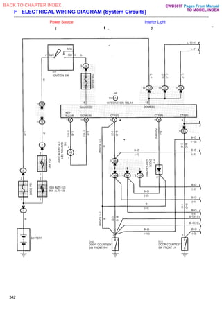
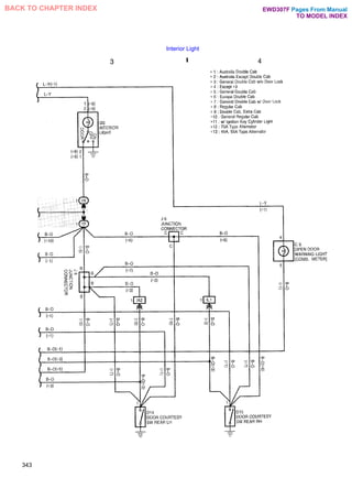
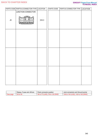
![SYSTEM CIRCUIT CONNECTORS
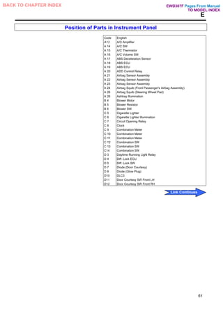
PARTS CODE PARTS & CONNECTOR TYPE LOCATION PARTS CODE PARTS & CONNECTOR TYPE LOCATION
C9
OPEN DOOR WARNING
LIGHT [COMB. METER]
343-4 D14
DOOR COURTESY SW
REAR LH
343-3
D7
DIODE (Door Courtesy)
342-2 D15
DOOR COURTESY SW
REAR RH
343-4
D11
DOOR COURTESY SW
FRONT LH (2-Door)
342-2 I16
IGNITION KEY CYLINDER
LIGHT BLUE
342-1
D11
DOOR COURTESY SW
FRONT LH (4-Door)
342-2 I17
IGNITION SW
342-1
D12
DOOR COURTESY SW
FRONT RH (2-Door)
342-2 I18
(A) INTEGRATION RELAY
342-1 342-2
D12
DOOR COURTESY SW
FRONT RH (4-Door)
342-2 I20
INTERIOR LIGHT
343-3
344
Pages From Manual
TO MODEL INDEX
BACK TO CHAPTER INDEX EWD307F](https://image.slidesharecdn.com/hiluxelecricalewd307f-220728231702-87b21402/85/HILUX-ELECRICAL-EWD307F-pdf-324-320.jpg)
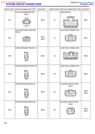
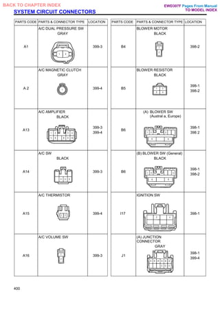
![SYSTEM CIRCUIT CONNECTORS
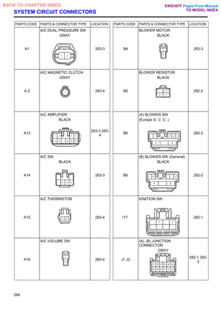
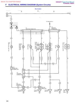
PARTS CODE PARTS & CONNECTOR TYPE LOCATION PARTS CODE PARTS & CONNECTOR TYPE LOCATION
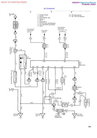
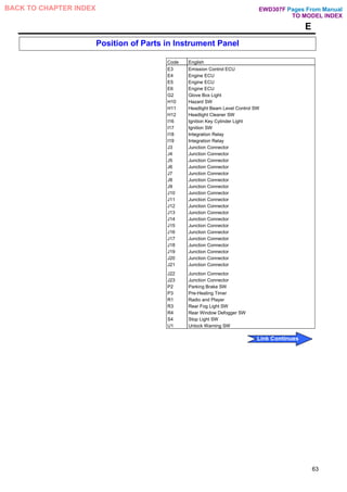
A14
A/CSW
BLACK
346-2
348-6
C10
REAR FOG LIGHT
INDICATOR LIGHT [COMB.
METER]
BLUE
349-8
A26
ASHTRAY ILLUMINATION
BLACK
347-4 C11
(C) METER ILLUMINATION
[COMB. METER]
BROWN
346-2
348-6
B6
(A) BLOWER SW (Australia,
Europe)
346-2
348-6
D9
DIODE (Idle-Up)
347-4
B6
(B) BLOWER SW (General)
BLACK
348-6 G2
GLOVE BOX LIGHT
BLACK
347-4
C6
CIGARETTE LIGHTER
ILLUMINATION
GRAY
347-3 H10
HAZARD SW
BLACK
347-3
348-5
C9
(A) METER ILLUMINATION
[COMB. METER]
346-2
348-6
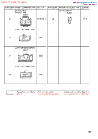
J1
(A) JUNCTION
CONNECTOR
GRAY
346-1
350
Pages From Manual
TO MODEL INDEX
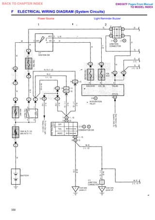
BACK TO CHAPTER INDEX EWD307F](https://image.slidesharecdn.com/hiluxelecricalewd307f-220728231702-87b21402/85/HILUX-ELECRICAL-EWD307F-pdf-330-320.jpg)
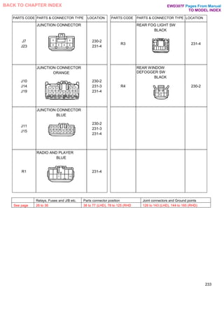
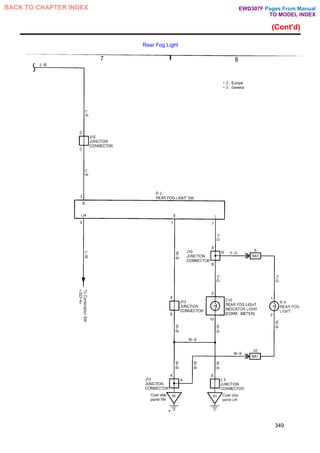
![SYSTEM CIRCUIT CONNECTORS
PARTS CODE PARTS & CONNECTOR TYPE LOCATION PARTS CODE PARTS & CONNECTOR TYPE LOCATION
02
A/T SHIFT LEVER
ILLUMINATION [O/D MAIN
SW]
347-3 R9
REAR FOG LIGHT (w/o Rear
Deck)
349-8
R1
RADIO AND PLAYER
BLUE
347-3
348-6
R3
REAR FOG LIGHT SW
BLACK
348-5
349-7
349-8
R4
REAR WINDOW
DEFOGGER SW
BLACK
346-2
348-5
R5
RHEOSTAT
BLACK
346-2
R9
REAR FOG LIGHT (w/ Rear
Deck)
349-8
352
Pages From Manual
TO MODEL INDEX
BACK TO CHAPTER INDEX EWD307F](https://image.slidesharecdn.com/hiluxelecricalewd307f-220728231702-87b21402/85/HILUX-ELECRICAL-EWD307F-pdf-332-320.jpg)
![SYSTEM CIRCUIT CONNECTORS
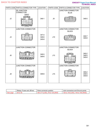
PARTS CODE PARTS & CONNECTOR TYPE LOCATION PARTS CODE PARTS & CONNECTOR TYPE LOCATION
D16
DOOR KEY LOCK AND
UNLOCK SW
GRAY
355-3 119
(B) INTEGRATION RELAY
GREEN
354-1
354-2
355-3
355-4
D17
(B) DOOR LOCK CONTROL
SW
355-3
355-4
J3
JUNCTION CONNECTOR
355-4
D18
DOOR LOCK MOTOR
FRONT LH
BLACK
354-1 J15
JUNCTION CONNECTOR
355-3
D19
DOOR LOCK MOTOR
FRONT RH
BLACK
354-2 J16
(A) JUNCTION
CONNECTOR
354-2
355-3
355-4
D20
DOOR LOCK MOTOR
REAR LH
BLACK
354-2 J17
(B) JUNCTION
CONNECTOR
354-2
355-3
355-4
D21
DOOR LOCK MOTOR
REAR RH
BLACK
354 2 P9
(A) DOOR LOCK
CONTROL SW
[POWER WINDOW
MASTER SW]
355-3
355-4
356
Pages From Manual
TO MODEL INDEX
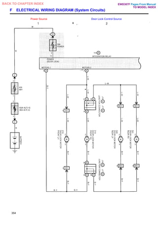
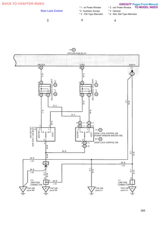
BACK TO CHAPTER INDEX EWD307F](https://image.slidesharecdn.com/hiluxelecricalewd307f-220728231702-87b21402/85/HILUX-ELECRICAL-EWD307F-pdf-336-320.jpg)
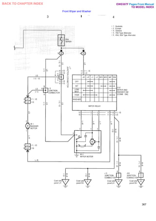
![SYSTEM CIRCUIT CONNECTORS
PARTS CODE PARTS & CONNECTOR TYPE LOCATION PARTS CODE PARTS & CONNECTOR TYPE LOCATION
C12
WIPER AND WASHER SW
[COMB. SW]
BLACK
367-3
367-4
J15
JUNCTION CONNECTOR
366-2
367-4
I17
IGNITION SW
366-1 R4
REAR WINDOW
DEFOGGER SW
BLACK
366-2
J3
JUNCTION CONNECTOR
366-2
367-4
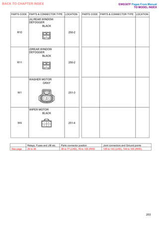
R10
(A) REAR WINDOW
DEFOGGER
BLACK
366-1
J5
JUNCTION CONNECTOR
BLUE
367 3 R11
(DREAR WINDOW
DEFOGGER
BLACK
366-1
J7
JUNCTION CONNECTOR
BLUE
367-3 W1
WASHER MOTOR
GRAY
367-3
J9
JUNCTION CONNECTOR
BLUE
366-2 W4
WIPER MOTOR
BLACK
367-4
368
Pages From Manual
TO MODEL INDEX
BACK TO CHAPTER INDEX EWD307F](https://image.slidesharecdn.com/hiluxelecricalewd307f-220728231702-87b21402/85/HILUX-ELECRICAL-EWD307F-pdf-348-320.jpg)
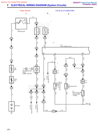
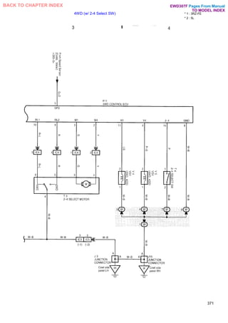
![SYSTEM CIRCUIT CONNECTORS
PARTS CODE PARTS & CONNECTOR TYPE LOCATION PARTS CODE PARTS & CONNECTOR TYPE LOCATION
A 8
ADD INDICATOR SW
GRAY
370-2 I17
IGNITION SW
370-1
C10
(B) 4WD INDICATOR
LIGHT [COMB. METER]
BLUE
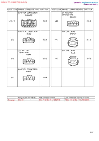
370 1 J3
JUNCTION CONNECTOR
371 3
C11
(C) 4WD INDICATOR
LIGHT [COMB. METER]
BROWN
370-1 J15
JUNCTION CONNECTOR
371-4
D1
DETECTION SW (Transfer
4WD Position)
GRAY
370-2 T3
2-4 SELECT MOTOR
371-3
D2
DETECTION SW (Transfer
L4 Position)
BLUE
370-2 T4
2-4 SELECT SW
371-4
F11
4WD CONTROL ECU
370-1
370-2
371-3
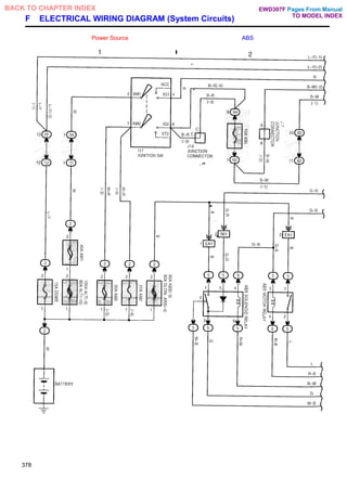
371-4
V4
VSV (2WD, ADD)
BROWN
371-4
372
Pages From Manual
TO MODEL INDEX
BACK TO CHAPTER INDEX EWD307F](https://image.slidesharecdn.com/hiluxelecricalewd307f-220728231702-87b21402/85/HILUX-ELECRICAL-EWD307F-pdf-352-320.jpg)
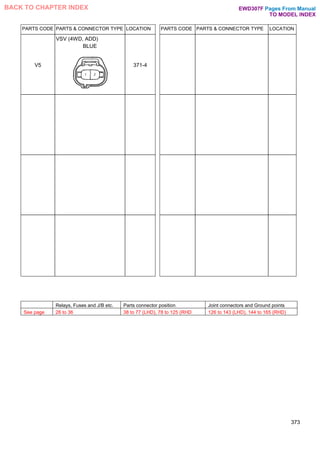
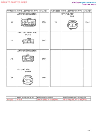
![SYSTEM CIRCUIT CONNECTORS
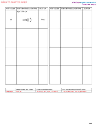
PARTS
CODE
PARTS & CONNECTOR TYPE LOCATION
A 8 ADD INDICATOR SW
GRAY
374-2
A20 ADD CONTROL RELAY 374-1 374-2
C10 (B) 4WD INDICATOR LIGHT
[COMB. METER]
BLUE
375-3
C11 (C) 4WD INDICATOR LIGHT
[COMB. METER] BROWN
375-3
C12 (A) HORN SW [COMB. SW]
BLACK
375-4
C13 (D HORN SW [COMB. SW] 375-4
PARTS
CODE
PARTS & CONNECTOR TYPE LOCATION
C14 HORN SW [COMB. SW] 375-4
D1 DETECTION SW (Transfer 4WD
Position) GRAY
375-3
D2 DETECTION SW (Transfer L4
Position) BLUE
375-4
H9 HORN BLACK 375-4
I17 IGNITION SW 374-1
J3 JUNCTION CONNECTOR 374-2
376
Pages From Manual
TO MODEL INDEX
BACK TO CHAPTER INDEX EWD307F](https://image.slidesharecdn.com/hiluxelecricalewd307f-220728231702-87b21402/85/HILUX-ELECRICAL-EWD307F-pdf-356-320.jpg)
![SYSTEM CIRCUIT CONNECTORS
PARTS CODE PARTS & CONNECTOR TYPE LOCATION PARTS CODE PARTS & CONNECTOR TYPE LOCATION
A 4
(A) ABS ACTUATOR
GRAY
379-3
379-4
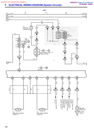
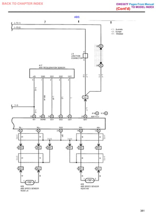
A28 A29
ABS SPEED SENSOR
REAR LH, RH
GRAY
381-7
381-8
A 5
(DABS ACTUATOR
BLACK
379-3
379-4
C3
CHECK CONNECTOR
(3RZ-FE, 1RZ-E, 2L-T)
BLACK
379-3
379-4
A 6
A 7
ABS SPEED SENSOR
FRONT LH, RH
GRAY
380-5 C3
CHECK CONNECTOR (5L,
2L)
BLACK
379-3
379-4
A17
ABS DECELERATION
SENSOR
BLACK
381-7 C10
(B) ABS WARNING LIGHT
[COMB. METER]
BLUE
380-5
A18
(A) ABS ECU
379-3
379-4
380-5
380-6
381-7
381-8
C11
(C) ABS WARNING LIGHT
[COMB. METER]
BROWN
380-5
A19
(B) ABS ECU
379-3
379-4
380-5
380-6
381-7
381-8
I17
IGNITION SW
378-1
382
Pages From Manual
TO MODEL INDEX
BACK TO CHAPTER INDEX EWD307F](https://image.slidesharecdn.com/hiluxelecricalewd307f-220728231702-87b21402/85/HILUX-ELECRICAL-EWD307F-pdf-362-320.jpg)
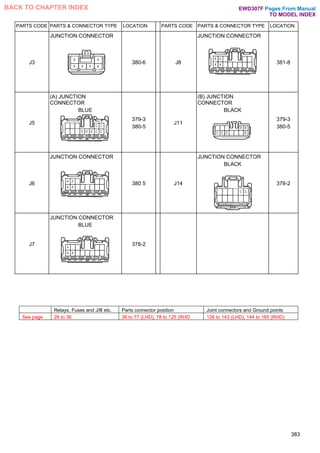
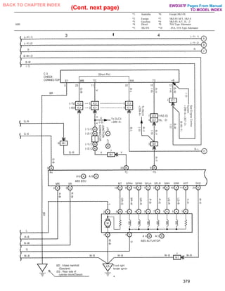
![SYSTEM CIRCUIT CONNECTORS
PARTS CODE PARTS & CONNECTOR TYPE LOCATION PARTS CODE PARTS & CONNECTOR TYPE LOCATION
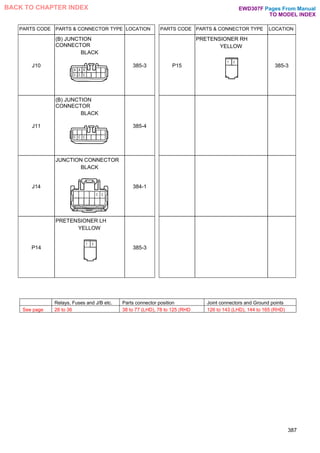
A21
(A) AIRBAG SENSOR
ASSEMBLY
YELLOW 384-1
384-2
385-3
385-4
C3
CHECK CONNECTOR (5L,
2L)
BLACK
385-3
385-4
A22
(B) AIRBAG SENSOR
ASSEMBLY
YELLOW 384-1
384-2
385-3
385-4
C9
(A) SRS WARNING
LIGHT [COMB.
METER]
385-3
A23
(C) AIRBAG SENSOR
ASSEMBLY
YELLOW 384-1
384-2
385-3
385-4
(C) SRS WARNING LIGHT
[COMB. METER]
BROWN
385-3
A24
AIRBAG SQUIB (Front
Passenger's Airbag
Assembly)
YELLOW
384-2 I17
IGNITION SW
384-1
A25
AIRBAG SQUIB (Steering
Wheel Pad)
YELLOW
384-1 J5
(A) JUNCTION
CONNECTOR
BLUE
385-3
385-4
C3
CHECK CONNECTOR
(3RZ-FE, 1RZ-E, 2L-T)
BLACK
385-3
385-4
J7
JUNCTION CONNECTOR
BLUE
384-2
386
Pages From Manual
TO MODEL INDEX
BACK TO CHAPTER INDEX
C11
EWD307F](https://image.slidesharecdn.com/hiluxelecricalewd307f-220728231702-87b21402/85/HILUX-ELECRICAL-EWD307F-pdf-366-320.jpg)