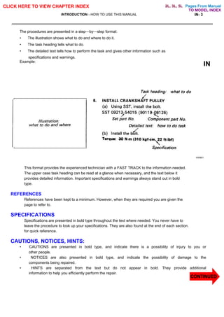
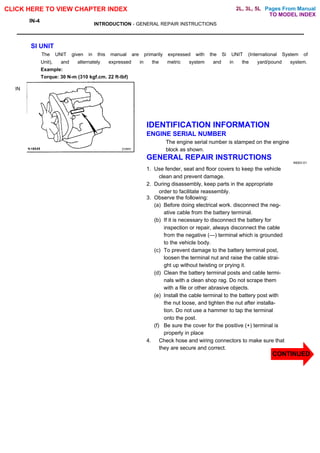
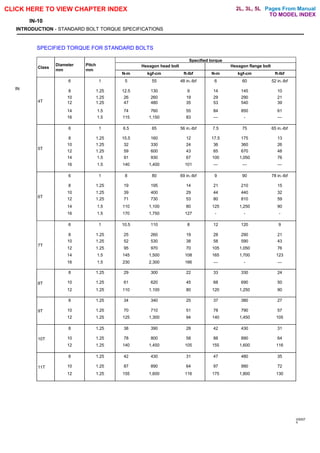
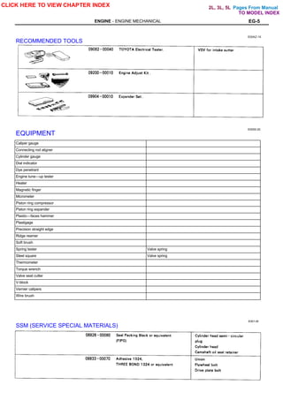
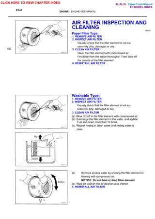
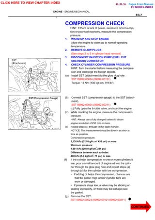
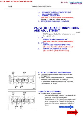
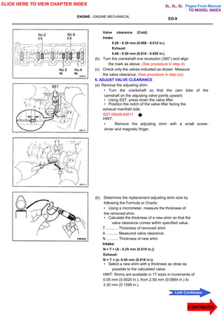
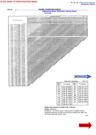
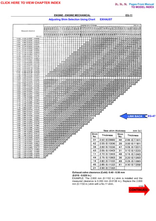
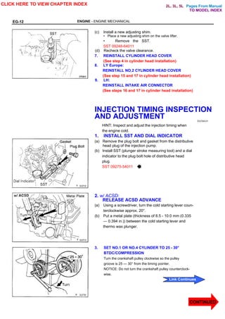
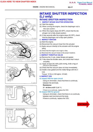
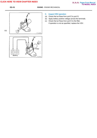
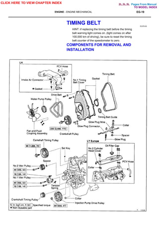
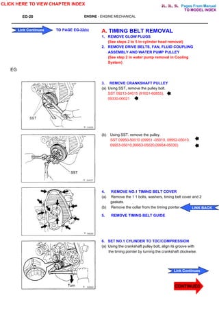
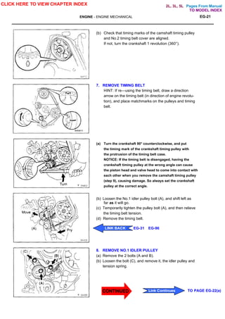
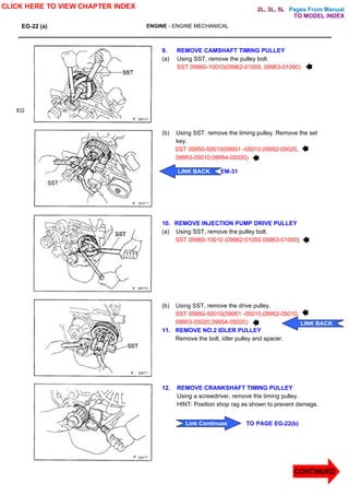
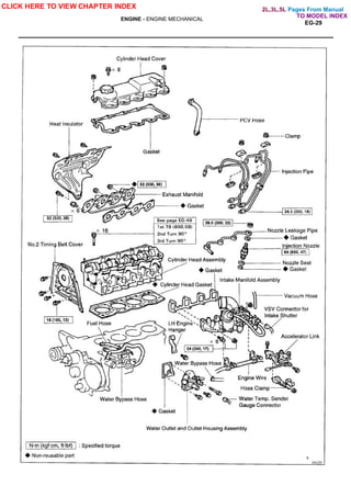
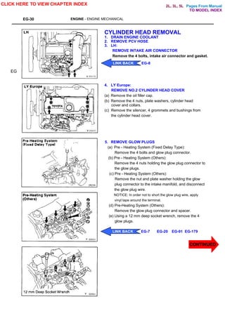
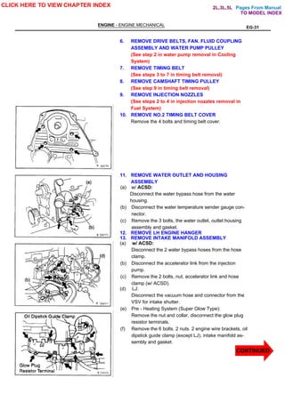
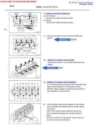
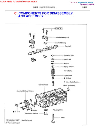
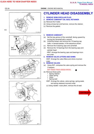
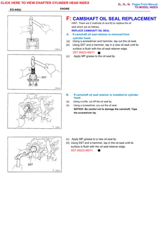
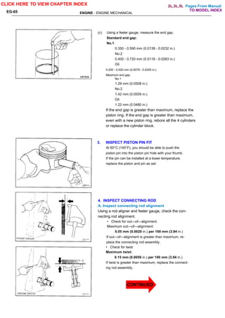
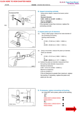
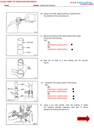
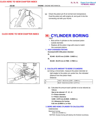
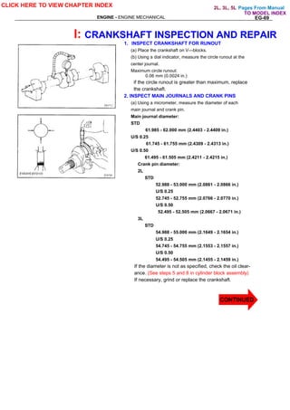
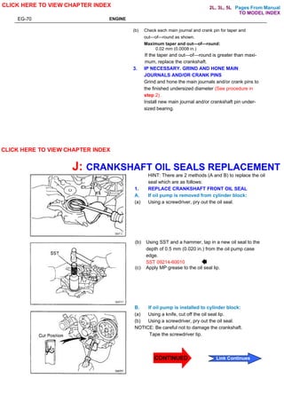
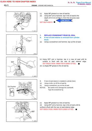
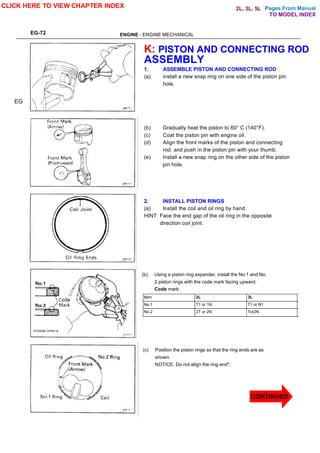
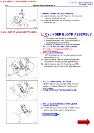
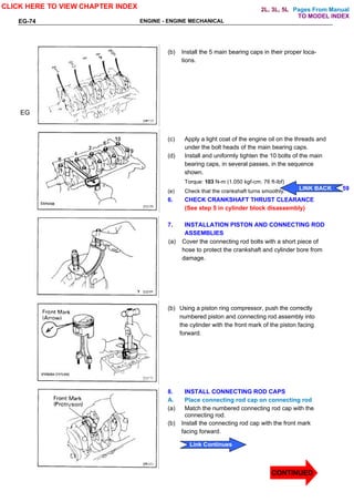
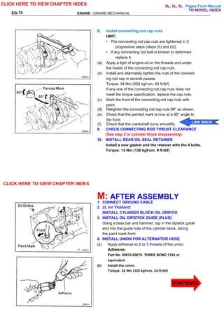
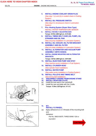
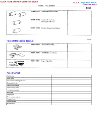
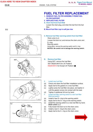
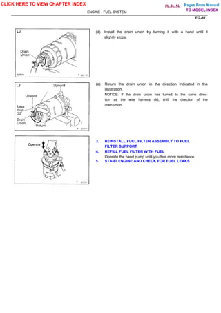
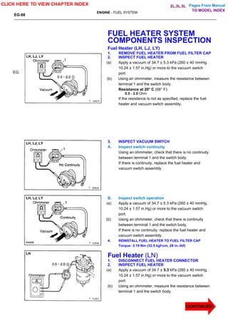
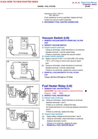
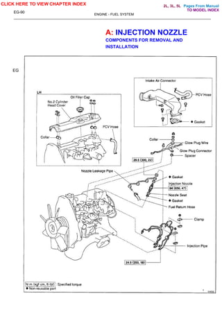
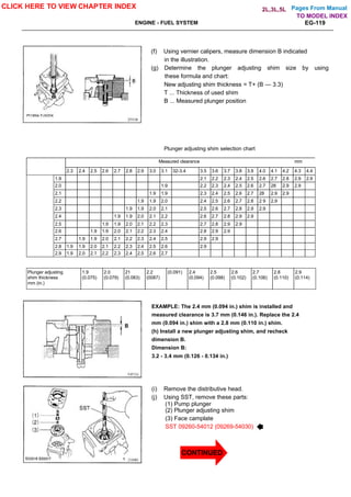
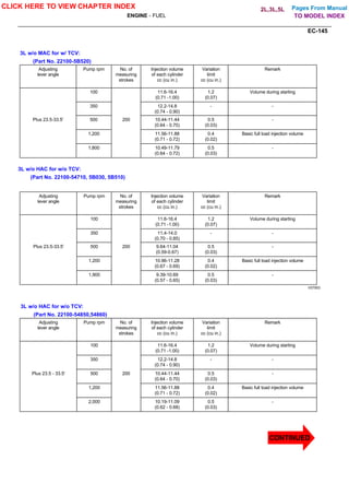
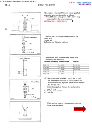
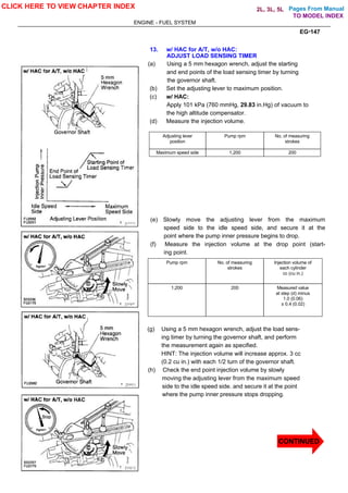
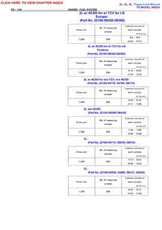
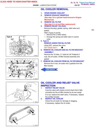
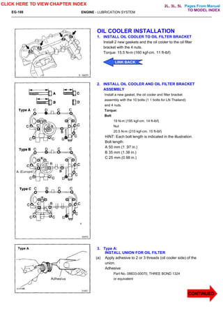
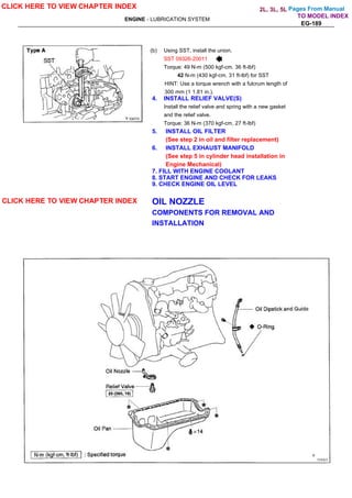
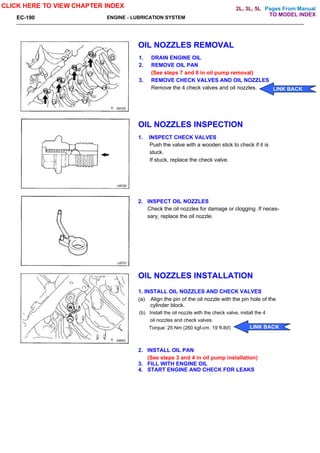
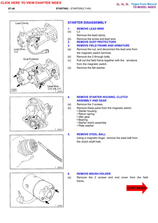
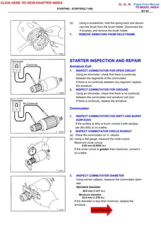
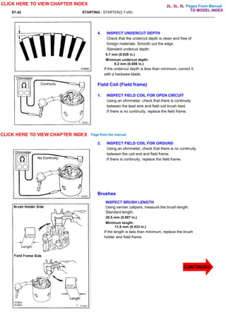
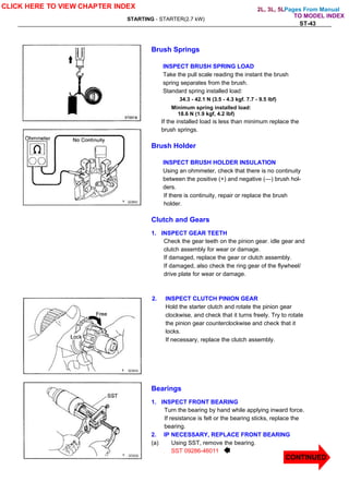
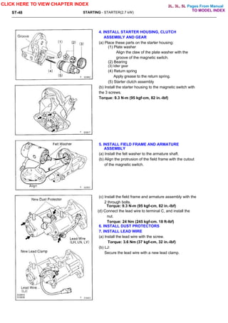
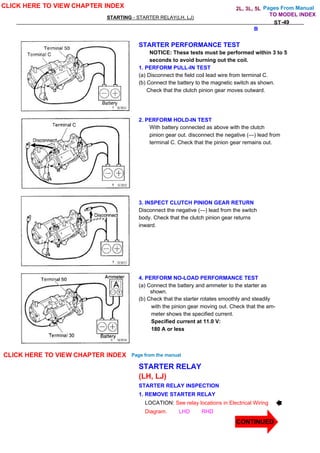
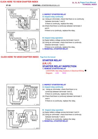
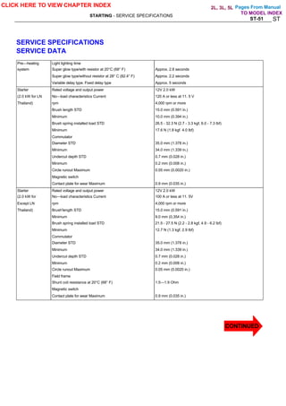
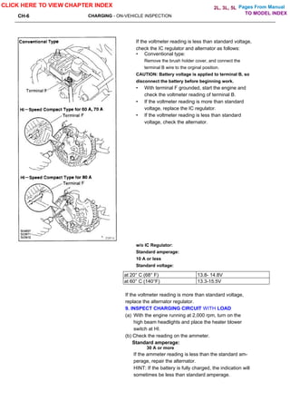
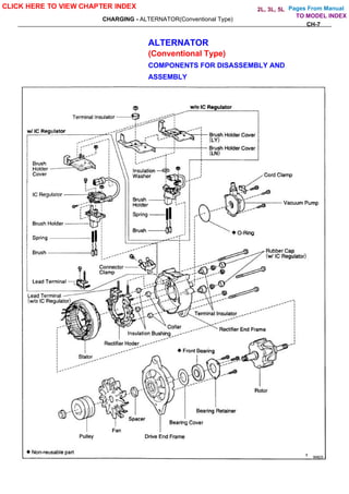
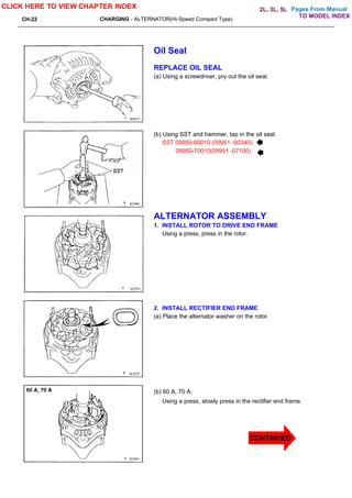
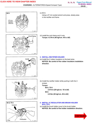
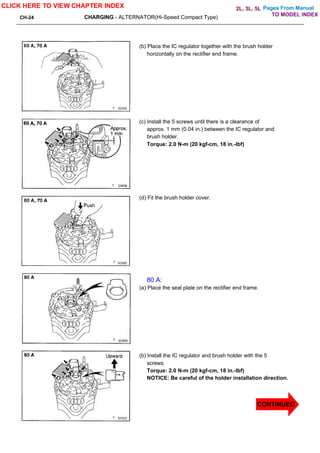
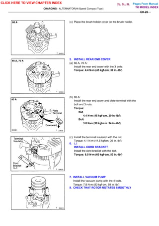
This repair manual provides information for servicing the 2L and 3L engines used in Toyota Land Cruiser, Hiace, Hilux, Dyna 100 and Dyna150 vehicles. It covers general service repairs and includes specifications, repair procedures, and other technical details. Technicians are advised to thoroughly read the manual, especially safety precautions, and use recommended tools and procedures. Standard bolt torque specifications are also provided as a reference.
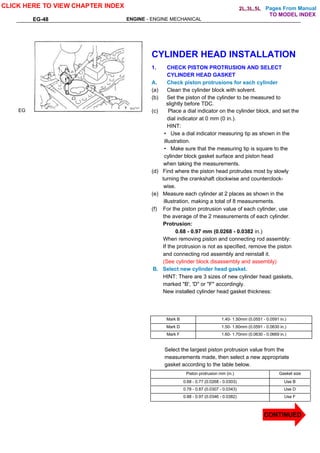
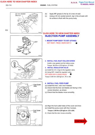
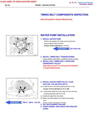
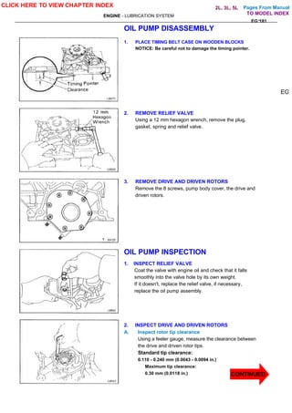
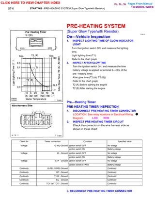

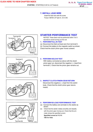
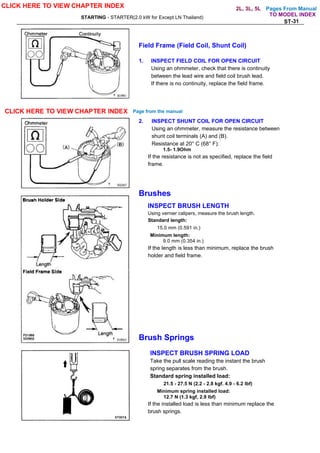
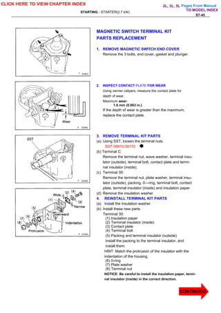
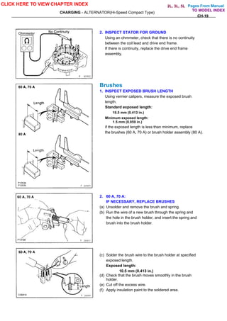


![DESIGN AND FABRICATION OF THE IBM 90-90 SEAT BELT CLAMP KIA VEHICLE[1].pptx 2...](https://cdn.slidesharecdn.com/ss_thumbnails/designandfabricationoftheibm90-90seatbeltclampkiavehicle1-260116160442-70ff67fc-thumbnail.jpg?width=640&height=640&fit=bounds)


