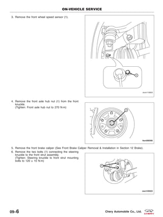
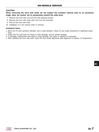
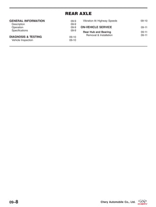
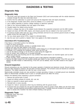
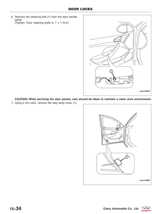
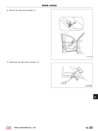
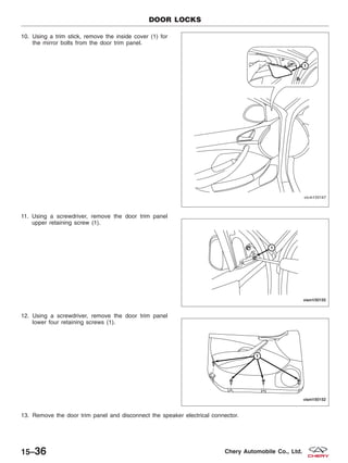
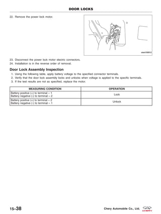
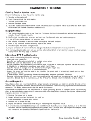
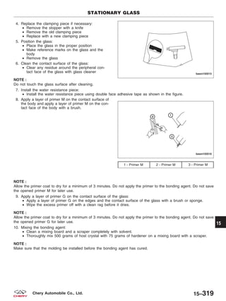
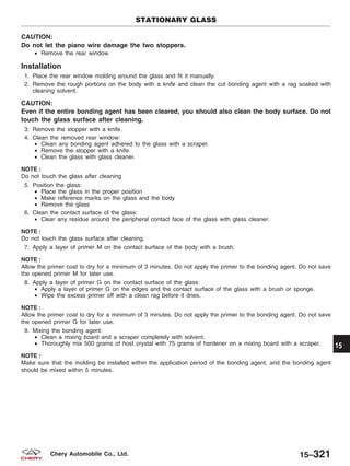
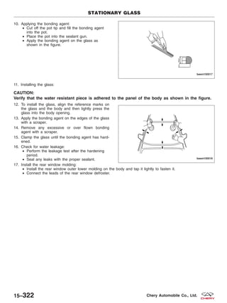
2009
CHERY
A3 Sedan
Service Manual
FOREWORD
This manual contains on-vehicle service
and diagnosis procedures for the Chery A3
Sedan.
A thorough familiarization with this manual
is important for proper repair and
maintenance. It should always be kept in a
handy place for quick and easy reference.
The contents of this manual, including
drawings and specifications, are the latest
available at the time of printing. As
modifications affecting repair or
maintenance occur, relevant information
supplementary to this volume will be made
available at Chery dealers. This manual
should be kept up-to-date.
Chery Automobile Company, Ltd. reserves the
right to alter the specifications and
contents of this manual without obligation
or advance notice.
All rights reserved. No part of this book
may be reproduced or used in any form or
by any means, electronic or mechanical—
including photocopying and recording and the
use of any kind of information storage and
retrieval system—without permission in
writing.
NOTE:
This A3 Sedan service manual only applies to the
following engines and transaxles:
• 1.6L with M/T
• 1.8L with M/T
Chery Automobile Company, Ltd.
Wuhu, Anhui Province, CHINA
CONTENTS
Title Section
GENERAL INFORMATION 01
ENGINE 02
ELECTRONIC ENGINE CONTROLS 03
FUEL DELIVERY 04
STARTING & CHARGING 05
COOLING 06
EXHAUST 07
TRANSAXLE 08
DRIVELINE & AXLE 09
SUSPENSION 10
STEERING 11
BRAKES 12
HEATING & AIR CONDITIONING 13
RESTRAINTS 14
BODY & ACCESSORIES 15
WIRING 16
ALPHABETICAL INDEX AI
© 2009 Chery Automobile Co., Ltd.
PRINTED AUGUST, 2009
GENERAL INFORMATION
01
CONTENTS page
Service Information . . . . . . . . . . . . . . . . . . . . . . . . . . . . . . . . . . . . . . . . . . . . . . . . . . . . . . . . . . . . . . . . . . . 01-1
Vehicle Information . . . . . . . . . . . . . . . . . . . . . . . . . . . . . . . . . . . . . . . . . . . . . . . . . . . . . . . . . . . . . . . . . . . 01-9
Electrical Circuit Diagnosis Information . . . . . . . . . . . . . . . . . . . . . . . . . . . . . . . . . . . . . . . . . . . . . . . . . 01-15
Electrical Information . . . . . . . . . . . . . . . . . . . . . . . . . . . . . . . . . . . . . . . . . . . . . . . . . . . . . . . . . . . . . . . . 01-20
SERVICE INFORMATION
HOW TO USE THIS MANUAL 01-2
Topics 01-2
Service Procedures 01-2
Diagnostic Procedures 01-2
Specifications 01-2
VEHICLE SERVICE PREPARATION 01-3
Preparation For Vehicle Service 01-3
Tools and Testing Equipment 01-3
Special Tools 01-4
Disconnection of the Negative Battery
Cable 01-4
PROPER SERVICE PRACTICES 01-5
Removal of Parts 01-5
Component Disassembly 01-5
Inspection of Parts 01-5
Arrangement of Parts 01-6
Cleaning of Parts 01-6
Component Reassembly 01-6
Adjustments 01-7
Rubber Parts and Rubber Tubing 01-7
Hose Clamps 01-8
Vise 01-8
Dynamometer 01-8
01
01–1Chery Automobile Co., Ltd.
HOW TO USE THIS MANUAL
Topics
This manual contains procedures for performing all required service operations.
The procedures are divided into three basic operations:
• Removal/Installation
• Disassembly/Assembly
• Inspection
Service Procedures
Most repair procedures begin with an illustration. It identifies the components, shows how the parts fit together and
describes visual part inspection. Removal & Installation procedures have written instructions.
Service procedures include the following elements:
• Detailed removal & installation instructions
• Integrated torque specifications
• Integrated illustrations
• Component specifications
Diagnostic Procedures
The diagnostic procedures are grouped into the following:
Diagnostic Trouble Codes (DTC)
• DTCs are important hints for repairing malfunctions that are difficult to simulate. Perform the specific DTC diag-
nostic inspection to quickly and accurately diagnose the malfunction.
Diagnostic Symptoms
• Symptom troubleshooting quickly determines the location of the malfunction according to symptom type.
Specifications
This manual contains specifications that are divided into the following groups:
• Torque specifications
• Clearance specifications
• Capacity specifications
01–2 Chery Automobile Co., Ltd.
VEHICLE SERVICE PREPARATION
Preparation For Vehicle Service
• Always be sure to cover fenders, seats and floor
areas before starting work.
Tools and Testing Equipment
• Be sure that all necessary tools and measuring
equipment are available before starting any work.
• Inspect the vehicle and reference any needed ser-
vice information before starting any work.
BESM010004
BESM010005
01
01–3Chery Automobile Co., Ltd.
Special Tools
• Use special tools when they are required.
Disconnection of the Negative Battery Cable
• Before beginning any work, turn the ignition switch
to LOCK, disconnect the negative battery cable and
then wait two minutes to allow the backup supply
of the air bag diagnostic monitor unit to deplete its
stored power. Disconnecting the battery cable
deletes the memories of the clock, audio and
DTCs, etc. Therefore, it is necessary to verify those
memories before disconnecting the cable.
VEHICLE SERVICE PREPARATION
BESM010006T
VISM010001
01–4 Chery Automobile Co., Ltd.
PROPER SERVICE PRACTICES
Removal of Parts
• While correcting a problem, also try to determine its
cause. Begin work only after first learning which
parts and subassemblies must be removed and dis-
assembled for replacement or repair. After removing
the part, plug all holes and ports to prevent foreign
material from entering.
Component Disassembly
• If the disassembly procedure is complex, requiring
many parts to be disassembled, make sure that all
parts are disassembled in a way that will not affect
their performance or external appearance. Identify
each part so reassembly can be performed easily
and efficiently.
Inspection of Parts
• When removed, inspect each part for possible mal-
function, deformation, damage or other problems.
BESM010007
BESM010008
BESM010009
01
01–5Chery Automobile Co., Ltd.
Arrangement of Parts
• All disassembled parts should be carefully arranged
for reassembly.
• Be sure to separate or otherwise identify the parts
to be replaced from those that will be reused.
Cleaning of Parts
• Carefully and thoroughly clean all parts to be
reused.
WARNING!
Using compressed air can cause dirt and other particles to fly out causing injury to the eyes. Wear protective
eyewear whenever using compressed air.
Component Reassembly
• Standard values, such as torques and certain
adjustments, must be strictly observed in the reas-
sembly of all parts. If removed, replace these parts
with new ones:
− Oil seals
− Gaskets
− O-rings
− Lock washers
− Cotter pins
− Nylon nuts
PROPER SERVICE PRACTICES
BESM010010
BESM010011
BESM010012
01–6 Chery Automobile Co., Ltd.
Depending on location:
• Apply sealant and gaskets, or both, to specified
locations. When sealant is applied, install parts
before sealant hardens to prevent leaks.
• Apply oil to the moving components of parts.
• Apply specified oil or grease at the prescribed loca-
tions (such as oil seals) before reassembly.
Adjustments
• Use suitable gauges and testers when making
adjustments.
Rubber Parts and Rubber Tubing
• Prevent gasoline or oil from getting on rubber parts
or tubing.
CAUTION:
Exposing rubber components to gasoline or oil can deteriorate the rubber components.
PROPER SERVICE PRACTICES
BESM010013
BESM010014
BESM010015
01
01–7Chery Automobile Co., Ltd.
Hose Clamps
• When reinstalling, position the hose clamp in the
original location on the hose and squeeze the
clamp lightly with large pliers to ensure a good fit.
Vise
• When using a vise, put protective plates in the
jaws of the vise to prevent damage to parts.
Dynamometer
• When test-running a vehicle on a dynamometer:
− Place a fan, preferably a vehicle-speed proportional type, in front of the vehicle.
− Connect an exhaust gas ventilation unit.
WARNING!
Exhaust gases can injure or kill. They contain carbon monoxide (CO), which is colorless and odorless. Breathing
it can make you unconscious and can eventually poison you.
− Cool the exhaust pipes with a fan.
− Keep the area around the vehicle uncluttered.
− Monitor the engine coolant temperature gauge.
PROPER SERVICE PRACTICES
BESM010016
BESM010017
01–8 Chery Automobile Co., Ltd.
VEHICLE INFORMATION
VEHICLE IDENTIFICATION NUMBER
(VIN) 01-10
VIN Location 01-10
VIN Identification Codes 01-11
INTERNATIONAL SYMBOLS 01-13
International Symbols 01-13
FASTENER USAGE 01-14
Fastener Usage 01-14
01
01–9Chery Automobile Co., Ltd.
VEHICLE IDENTIFICATION NUMBER (VIN)
VIN Location
The VIN is printed on a plastic tag attached to the top left corner of the upper instrument panel. The VIN is also
found on the vehicle certification (VC) label.
Vehicle Identification Number (VIN) Tag Location
VISM010002
01–10 Chery Automobile Co., Ltd.
VIN Identification Codes
The vehicle identification number (VIN) is a 17-digit
combination of letters and numbers.
NUMBER
DESIGNATION
DEFINITION
1 World Manufacturer Identifier
2 Brand Of The Vehicle
3 Vehicle Chassis Type
4 Transmission Type
5 Engine Type
6 Restraint System
7 Check Digit
8 Model Year
9 Assembly Plant
10 Production Sequence Number
• Digits #1, #2, #3 The first 3 vehicle identification number (VIN) positions are the world manufacturer identifier:
− ЉLVVЉ represents Chery Automobile Co., Ltd.
• Digit #4 The fourth digit of the VIN code represents the brand of the vehicle:
− The brand ЉCheryЉ is represented by the letter ЉDЉ.
• Digit #5 The fifth digit of the VIN code represents the body configuration of the vehicle:
− ЉAЉ represents three compartments, five-door, and 4X2.
− ЉBЉ represents two compartments, five-door, and 4X2.
− ЉCЉ represents three compartments, four-door, two-lid, and 4X2.
− ЉDЉ represents two compartments, five-door, and 4X4.
• Digit #6 The sixth digit of VIN code represents the type of transmission:
− Љ1Љ represents manual transmission.
− Љ2Љ represents automatic transmission.
• Digit #7 The seventh digit of VIN code represents the type of engine:
− Љ1Љ represents electronically controlled gasoline engines 1.5L - 2.0L (excluding 2.0L) series.
− Љ2Љ represents engines smaller than 1.5L (excluding 1.5L).
− Љ4Љ represents 2.0L - 2.5L engines (excluding 2.5L).
VEHICLE IDENTIFICATION NUMBER (VIN)
BESM010002
01
01–11Chery Automobile Co., Ltd.
• Digit #8 The eighth digit of VIN code represents the Restraint System:
− ЉAЉ represents manual safety belts.
− ЉBЉ represents manual safety belts plus air bags in the front row.
• Digit #9 The ninth digit of VIN code is the check digit:
− It is to check accuracy of VIN record, and is made out through computation after confirming the other six-
teen digits of VIN
• Digit #10 The tenth VIN position represents the model year code:
− Љ5Љ represents the year 2005
• Digit #11 The eleventh VIN position represents the assembly plant code:
− ЉDЉ represents the ЉChery Automobile Co., Ltd.Љ
• Digits #12, #13, #14, #15, #16, #17 The last six VIN positions represent the production sequence number.
− This represents the actual production number of the vehicle.
VEHICLE IDENTIFICATION NUMBER (VIN)
01–12 Chery Automobile Co., Ltd.
INTERNATIONAL SYMBOLS
International Symbols
The graphic symbols illustrated in the following International Control and Display Symbols chart are used to identify
various instrument controls. The symbols correspond to the controls and displays that are located on the instrument
panel.
1 - High Beam
2 - Fog Lamps
3 - Headlamp, Parking Lamps, Panel Lamps
4 - Turn Signals
5 - Hazard Warning
6 - Windshield Washer
7 - Windshield Wiper
8 - Windshield Wiper and Washer
9 - Windshield Defroster
10 - Blower Motor Fan
11 - Rear Window Defroster
12 - Rear Window Wiper
13 - Rear Window Washer
14 - Fuel
15 - Engine Coolant Temperature
16 - Battery Charging Condition
17 - Engine Oil
18 - Seat Belt
19 - Brake Failure
20 - Parking Brake
21 - Hood
22 - Trunk
23 - Horn
24 - Lighter
BESM010003
01
01–13Chery Automobile Co., Ltd.
FASTENER USAGE
Fastener Usage
WARNING!
Use of an incorrect fastener may result in component damage. Failure to follow these instructions may result in
personal injury or death.
Fasteners and torque specification references in this Service Manual are identified in metric format.
During any maintenance or repair procedures, it is important to salvage all fasteners (nuts, bolts, etc.) for reassembly.
If the fastener is not salvageable, a fastener of equivalent specification must be used.
01–14 Chery Automobile Co., Ltd.
ELECTRICAL CIRCUIT DIAGNOSIS INFORMATION
DIAGNOSING AN ELECTRICAL
FAILURE 01-16
Performing Efficient Electrical Circuit
Diagnosis and Troubleshooting 01-16
Electrical Circuit Failure Simulation Tests 01-16
Precautions For Handling Control Modules
and Electrical Components 01-18
How To Check Electrical Connectors 01-19 01
01–15Chery Automobile Co., Ltd.
DIAGNOSING AN ELECTRICAL FAILURE
Performing Efficient Electrical Circuit Diagnosis and Troubleshooting
STEP DESCRIPTION
Step 1
Obtain detailed information about the conditions and the environment when the electrical
incident occurred.
Step 2
Operate the affected system, road test the vehicle if necessary.
Verify the parameter of the incident.
If the problem cannot be duplicated, refer to “Electrical Failure Simulation Tests”.
Step 3
Gather the proper diagnosis material together including:
• Electrical Power Supply Routing Diagram
• System Operation Descriptions
• Applicable Service Manual Sections
• Check for any Service Bulletins
• Identify where to begin diagnosis based upon your knowledge of the system operation
and the customer comments.
Step 4
Inspect the system for mechanical binding, loose connectors or wiring damage.
Determine which circuits and components are involved and diagnose using the Electrical
Power Supply Routing Diagram and Harness Layouts.
Step 5 Repair the circuit or replace the component as necessary.
Step 6
Operate the system in all modes. Verify the system functions properly under all conditions.
Confirm you have not inadvertently created an additional new incident during your
diagnosis or repair steps.
Electrical Circuit Failure Simulation Tests
Often the symptom is not present when the vehicle is brought in for service. If possible, re-create the conditions
present at the time of the incident. Doing so may help avoid a No Trouble Found Diagnosis. The following illustrates
tests to simulate the conditions/environment under which the owner experiences an electrical incident.
The tests are broken into the seven following topics:
• Vehicle Vibration Test
• Heat Sensitive Test
• Freezing Test
• Water Intrusion Test
• Electrical Load Test
• Cold or Hot Start Up Test
• Voltage Drop Test
NOTE :
Always get a thorough description of the incident from the customer. It is important for simulating the conditions of
the problem.
01–16 Chery Automobile Co., Ltd.
Vehicle Vibration Test
The problem may occur or become worse while driving on a rough road or when the engine is vibrating (idle with A/C
on). In such a case, check for a vibration related condition. Refer to the following vehicle areas:
Connectors & Harness
• Determine which connectors and wiring harness would affect the electrical system you are inspecting. Gently
shake each connector and harness while monitoring the system for the incident you are trying to duplicate. This
test may indicate a loose or poor electrical connection.
NOTE :
Connectors can be exposed to moisture. It is possible for a thin film of corrosion to form on the connector terminals.
A visual inspection may not reveal this without disconnecting the connector. If the problem occurs intermittently, per-
haps the problem is caused by corrosion. It is a good idea to disconnect, inspect and clean the terminals on related
connectors in the system.
Sensors & Relays
• Gently apply a slight vibration to sensors and relays in the system you are inspecting. This test may indicate a
loose or poorly mounted sensor or relay.
Engine Compartment
• There are several reasons a vehicle or engine vibration could cause an electrical complaint. Some of the things
to check for are:
− Connectors not fully seated.
− Wiring harness not long enough and is being stressed due to engine vibrations or rocking.
− Wires laying across brackets or moving components.
− Loose, dirty or corroded ground wires.
− Wires routed too close to hot components.
• To inspect components under the hood, start by verifying the integrity of the ground connections (See Ground
Inspection described later). First, verify that the system is properly grounded. Then check for any loose connec-
tions by gently shaking the wiring or components as previously explained. Using the wiring diagrams, inspect
the wiring for continuity.
Behind The Instrument Panel
• An improperly routed or improperly clamped harness can become pinched during accessory installation. Vehicle
vibration can aggravate a harness which is routed along a bracket or near a mounting screw.
• An unclamped or loose harness can cause wiring to be pinched by seat components (such as slide guides)
during vehicle vibration. If the wiring runs under seating areas, inspect wire routing for possible damage or
pinching.
Heat Sensitivity Test
The customer’s concern may occur during hot weather or after the vehicle has sat for a short time. In such cases you
will want to check for a heat sensitive condition.
To determine if an electrical component is heat sensitive, heat the component with a heat gun or equivalent.
CAUTION:
Do not heat components above 60 °C (140 °F).
If the incident occurs while heat testing the component, replace or properly insulate the component as needed.
Freezing Test
The customer may indicate the incident goes away after the vehicle warms up (winter time). The cause could be
related to water freezing somewhere in the wiring/electrical system. There are two methods to check for this:
• The first method is to arrange for the owner to leave the vehicle overnight. Make sure it will get cold enough to
demonstrate the complaint. Leave the vehicle parked outside overnight. In the morning, do a quick and thor-
ough diagnosis of those electrical components which could be affected.
• The second method is to put the suspect component into a freezer long enough for any water to freeze. Rein-
stall the part into the vehicle and check for the reoccurrence of the incident. If it occurs, repair or replace the
component as needed.
DIAGNOSING AN ELECTRICAL FAILURE
01
01–17Chery Automobile Co., Ltd.
Water Intrusion Test
The incident may occur only during high humidity or in rainy/snowy weather. In such cases the incident could be
caused by water intrusion on an electrical part. This can be simulated by soaking the car or running it through a car
wash.
Electrical Load Test
The incident may be electrical load sensitive. Perform diagnosis with all accessories (including A/C, rear window
defogger, radio, fog lamps) turned on.
Cold or Hot Starting Test
On some occasions an electrical incident may occur only when the vehicle is started cold, or it may occur when the
vehicle is restarted hot shortly after being turned off. In these cases you may have to keep the vehicle overnight to
make a proper diagnosis.
Voltage Drop Test
Voltage drop tests are often used to find components or circuits which have excessive resistance. A voltage drop in
a circuit is caused by a resistance in the circuit during operation.
• Check the circuit using a Digital Multimeter (DMM).
• When measuring resistance with a DMM, remember that contact by a single strand of wire will give a reading
of 0 ohms. This would indicate a good circuit. When the circuit operates, this single strand of wire is not able
to carry the current. The single strand will have a high resistance to the current. This will be indicated as a
slight voltage drop.
• Unwanted resistance can be caused by the following:
− Undersized wiring (single strand example)
− Corrosion on switch contacts
− Loose wire connections or splices.
Precautions For Handling Control Modules and Electrical Components
• Never reverse polarity of battery terminals.
• Only install components specified for the vehicle.
• Before replacing the control module, check the input and output and functions of the components.
• When disconnecting components:
− Do not apply excessive force when disconnecting a connector.
− If a connector is installed by tightening bolts, loosen mounting bolt, then remove it by hand.
• When connecting components:
− Before installing a connector, make sure the terminal is not bent or damaged, and then correctly connect it.
− When installing a connector by tightening bolts, tighten the mounting bolt until the painted area of the con-
nector becomes even with the surface.
• Do not apply excessive shock to the control module by dropping or hitting it.
• Be careful to prevent condensation in the control module due to rapid temperature changes and do not let
water or rain get on it. If water is found in the control unit, dry it fully and then install it in the vehicle.
• Be careful not to let oil get on the control module connector.
• Avoid cleaning the control module with volatile oil.
DIAGNOSING AN ELECTRICAL FAILURE
01–18 Chery Automobile Co., Ltd.
• When using a DMM, be careful not to let the test probes touch each other causing a short circuit. Prevent the
power transistor in the control module from being
shorted to damaging battery voltage.
• When checking input and output signals of the con-
trol module, use the specified test adapter (if appli-
cable).
How To Check Electrical Connectors
Many electrical problems are caused by faulty electrical
connections or wiring. It is also possible for a sticking
component or relay to cause a problem. Before con-
demning a component or wiring assembly, always
check the electrical connectors for good continuity.
How To Probe Connectors
• Connector damage and an intermittent connection
can result from improperly probing the connector
during circuit checks.
• The probe of a DMM may not correctly fit the con-
nector cavity. To correctly probe the connector, fol-
low the procedures below using a “T” pin. For the
best contact grasp the “T” pin using an alligator
clip.
Probing From Harness Side
• If the connector has a rear cover connector,
remove the rear cover before probing the terminal.
• Do not probe waterproof connectors from the har-
ness side. Damage to the seal between the wire
and connector may result.
Probing From Terminal Side
• Female Terminal:
− Do not insert any object into the female connector, that is bigger than the male terminal.
• Male Terminal:
− Carefully probe the contact surface of each terminal using a “T” pin. Do not bend terminal.
How To Check Proper Contact Spring Tension Of Terminal
• An enlarged contact spring of a terminal may create intermittent signals in the circuit.
• If an intermittent open circuit occurs, follow the procedure below to inspect for open wires and enlarged contact
spring of female terminal.
− Use a male terminal which matches the female terminal.
− Disconnect the suspected faulty connector and hold it terminal side up.
− While holding the wire of the male terminal, attempt to insert the male terminal into the female terminal.
− While moving the connector, check whether the male terminal can be easily inserted or not.
NOTE :
If the male terminal can be easily inserted into the female terminal, replace the female terminal.
DIAGNOSING AN ELECTRICAL FAILURE
LTSMD030028
01
01–19Chery Automobile Co., Ltd.
ELECTRICAL INFORMATION
HOW TO READ ELECTRICAL
SCHEMATICS 01-21
Connector Symbols 01-21
Option Splices 01-22
Electrical Schematic - Example 01-23
HOW TO LOCATE ELECTRICAL
SCHEMATICS IN THE SERVICE
MANUAL 01-25
Electrical Schematic Index 01-25
01–20 Chery Automobile Co., Ltd.
HOW TO READ ELECTRICAL SCHEMATICS
Connector Symbols
• Connector symbols shown from the terminal side
are enclosed by a single line and followed by the
direction mark.
• Connector symbols shown from the harness side
are enclosed by a double line and followed by the
direction mark.
• Most of the connector symbols in the wiring dia-
grams are shown from the terminal side.
• In wiring diagrams, male terminals are shown in
black and female terminals are shown in white.
NOTE :
Connector guides for male terminals are shown in black
and female terminals in white in wiring diagrams.
BESMW010003T
BESMW010004T
01
01–21Chery Automobile Co., Ltd.
Option Splices
• Option splices are shown with solid diamond-shaped boxes with identification numbers inside.
HOW TO READ ELECTRICAL SCHEMATICS
BESMW010002T
01–22 Chery Automobile Co., Ltd.
Electrical Schematic - Example
HOW TO READ ELECTRICAL SCHEMATICS
BESMW010001T
01
01–23Chery Automobile Co., Ltd.
Below is a list of the symbols and their definitions that are used in the wiring diagrams.
NUMBER ITEM DESCRIPTION
1 Power source
This represents the condition when the system receives
battery positive voltage.
2 Fuse The single line represents that this is a fuse.
3 Current rating This represents the current rating of the fuse.
4 Fuse location
This represents the location of the fuse in the Power
Fuse Box or Front Fuse and Relay Box.
5 Connectors
This represents connector E-101 is female and
connector C-101 is male.
6 Terminal number This represents the terminal number of a connector.
7 Component name This represents the name of a component.
8 Connector number
This represents the connector number.
The letter represents which harness the connector is
located in.
9 Splice
The shaded circle represents that the splice is always
on the vehicle.
10 Optional splice
The open circle represents that the splice is optional
depending on vehicle application.
11 Option abbreviation
This represents that the circuit is optional depending on
vehicle application.
12 Ground (GND)
This represents the ground connection (See Ground
Distribution in Section 16 Wiring).
Ground connector number has no view face.
13 Page crossing
This arrow represents that the circuit continues to an
adjacent page.
The ЉAЉ corresponds with the ЉAЉ on the adjoining page
of the electrical schematic.
14 Data link
This represents that the system branches to another
system identified by cell data code.
15 Option description
This represents a description of the option abbreviation
used on the page.
16 Connector views
This represents the connector information.
This component side is described by the connector
symbols.
17 Connector color
This shows a code for the color of the connector:
B = Black
W = White
R = Red
G = Green
L = Blue
Y = Yellow
BR = Brown
O = Orange
GR = Gray
18 Shielded line
The line enclosed by broken line circle represents
shielded wire.
19 Light-emitting diodes
As an illumination tool, in the circuit and instrument
cluster.
HOW TO READ ELECTRICAL SCHEMATICS
01–24 Chery Automobile Co., Ltd.
HOW TO LOCATE ELECTRICAL SCHEMATICS IN THE
SERVICE MANUAL
Electrical Schematic Index
The following table shows where to locate a specific electrical schematic for a vehicle component or system. The
electrical schematics are found throughout the service manual and are easily identified by their components or vehi-
cle systems.
NOTE :
Some service manual chapters DO NOT contain electrical schematics, and will be identified as None in the Com-
ponent/Vehicle System column.
SERVICE MANUAL CHAPTER COMPONENT / VEHICLE SYSTEM
01 - General Information • None
02 - Engine • None
03 - Electronic Engine Controls
• Engine Control Module (ECM)
• Engine Coolant Temperature Sensor
• Knock Sensor
• Upstream Oxygen Sensor
• Downstream Oxygen Sensor
• Crankshaft Position Sensor
• Camshaft Position Sensor
• Ignition Coil
• Canister Control Valve
• Front Fuse and Relay Box
• A/C Compressor
• Immobilizer
• Fuel Injectors
• Manifold Absolute Pressure Sensor (1.6L Only)
• Air Flow Sensor (1.8L Only)
• Accelerator Pedal Position Sensor
• Vehicle Speed Sensor
• Throttle Pedal Position Sensor
• Power Steering Switch
• Clutch Pedal Switch (if equipped)
• Electronic Throttle Control Actuator
04 - Fuel Delivery
• Fuel Injectors
• Fuel Level Sensor and Fuel Pump
05 - Starting & Charging
• Starter Motor
• Ignition Switch
• Clutch Pedal Switch (if equipped)
• Generator
06 - Cooling System • Cooling Fan
01
01–25Chery Automobile Co., Ltd.
SERVICE MANUAL CHAPTER COMPONENT / VEHICLE SYSTEM
07 - Exhaust • None
08 - Transaxle & Transfer Case
• Manual Transaxle Assembly
• Backup Lamp Switch
09 - Driveline & Axle • None
10 - Suspension • None
11 - Steering
• Power Steering Switch
• Electronic Power Steering (EPS) Control Unit
• Steering Torque Sensor
• EPS Motor
12 - Brakes
• Antilock Brake System (ABS) Module
• Wheel Speed Sensors
• Brake Switch
• Parking Brake Switch
• Brake Fluid Level Switch
13 - Heating & Air Conditioning
• Automatic Temperature Control System
• Blower Motor
• In-Car Temperature Sensor
• Outside Temperature Sensor
• A/C Compressor
• Refrigerant Pressure Switch
14 - Restraints
• Airbag Module
• Seat Belt Buckle Switch
• Front Crash Sensors
• Driver Airbag
• Passenger Airbag
HOW TO LOCATE ELECTRICAL SCHEMATICS IN THE SERVICE MANUAL
01–26 Chery Automobile Co., Ltd.
SERVICE MANUAL CHAPTER COMPONENT / VEHICLE SYSTEM
15 - Body & Accessories
• Windshield Wiper Motor
• Windshield Washer Motor
• Rear Window Defroster
• Power Door Locks
• Power Windows
• Power Mirrors
• Radio
• Interior Lights
• Exterior Lights
• Oil Pressure Switch
• Warning Buzzer
• Front Body Control Module (FBCM)
• Rear Body Control Module (RBCM)
• Instrument Cluster
• Driver Information Center
• Key Switch
• Power Outlet
• Data Link Connector
• Immobilizer
• Horn
16 - Wiring
• Power Distribution
• Front Fuse and Relay Box
• Power Fuse Box
• Ignition Switch
• Ground Distribution
Abbreviation List
TERM ABBREVIATION
Antilock Brake System ABS
Accelerator Sensor AES
Accelerator Pedal Position Sensor APS
Automatic Temperature Control ATC
Body Control Module BCM
Brake Pressure Sensor BPS
Camshaft Position Sensor CMP Sensor
Clutch Pedal Position Switch CPP Switch
Crankshaft Position Sensor CKP Sensor
Data Link Connector DLC
Diagnostic Trouble Code DTC
Engine Control Module ECM
Engine Coolant Temperature ECT
Engine Speed RPM
Evaporative Emission EVAP
Evaporative Emission Canister EVAP Canister
Evaporative Emission System EVAP System
Exhaust Gas Recirculation Valve EGR Valve
Electronic Power Steering EPS
HOW TO LOCATE ELECTRICAL SCHEMATICS IN THE SERVICE MANUAL
01
01–27Chery Automobile Co., Ltd.
TERM ABBREVIATION
Electronic Stability Program ESP
Front Left Wheel Speed Sensor FLS
Front Right Wheel Speed Sensor FRS
Rear Left Wheel Speed Sensor RLS
Rear Right Wheel Speed Sensor RRS
Ground GND
Heated Oxygen Sensor O2S
Idle Air Control IAC
Intake Air Temperature IAT
Ignition IGN
Ignition Control IC
Injector INJ
Input Shaft Speed Sensor ISS Sensor
Knock Sensor KS
Manifold Absolute Pressure MAP
Mass Air Flow MAF
Oil Pressure Switch OPS
Output Shaft Speed Sensor OSS Sensor
Positive Crankcase Ventilation Valve PCV Valve
Power Supply PWR
SRS Airbag Control System SRC
Throttle Position Sensor TPS
Transmission Control Module TCM
Turbine Speed Sensor TSS
Vehicle Identification Number VIN
Electronic Pedal Control EPC
Vehicle Speed Sensor VSS
HOW TO LOCATE ELECTRICAL SCHEMATICS IN THE SERVICE MANUAL
01–28 Chery Automobile Co., Ltd.
ENGINE
02
CONTENTS page
1.6L & 1.8L Engine Mechanical . . . . . . . . . . . . . . . . . . . . . . . . . . . . . . . . . . . . . . . . . . . . . . . . . . . . . . . . . 02-1
1.6L & 1.8L ENGINE MECHANICAL
GENERAL INFORMATION 02-3
Description 02-3
Operation 02-3
Specifications 02-3
Special Tools 02-7
Lubrication System 02-10
DIAGNOSIS & TESTING 02-13
Engine Performance Diagnostics 02-13
Engine Mechanical Diagnostics 02-14
Cylinder Compression Pressure Test 02-15
Cylinder Head Gasket Test 02-15
ON-VEHICLE SERVICE 02-16
Accessory Drive Belt - With
Conventional Power Steering 02-16
Removal & Installation 02-16
Accessory Drive Belt - With Electronic
Power Steering 02-17
Removal & Installation 02-17
Air Cleaner Element 02-18
Removal & Installation 02-18
Air Cleaner Housing 02-18
Removal & Installation 02-18
Cylinder Head Cover 02-19
Removal & Installation 02-19
Camshaft 02-20
Removal & Installation 02-20
Cylinder Head 02-23
Removal & Installation 02-23
Front Crankshaft Oil Seal 02-25
Removal & Installation 02-25
Rear Crankshaft Oil Seal 02-26
Removal & Installation 02-26
Engine Mounts 02-28
Left Mount - Removal & Installation 02-28
Right Mount - Removal & Installation 02-29
Rear Mount - Removal & Installation 02-30
Engine Assembly 02-30
Removal & Installation 02-30
Engine Timing Belt 02-38
Removal & Installation 02-38
Intake Manifold 02-42
Removal & Installation 02-42
Exhaust Manifold 02-44
Removal & Installation 02-44
Idler Pulley 02-46
Removal & Installation 02-46
Oil Filter 02-46
Removal & Installation 02-46
Oil Pan 02-47
Removal & Installation 02-47
Oil Pump 02-48
Removal & Installation 02-48
Oil Strainer 02-49
Removal & Installation 02-49
02
02–1Chery Automobile Co., Ltd.
ENGINE UNIT REPAIR 02-50
Engine Block 02-50
Specifications 02-50
Disassembly 02-50
Inspection 02-52
Assembly 02-52
Pistons 02-53
Specifications 02-53
Disassembly 02-54
Inspection 02-55
Assembly 02-57
Connecting Rods 02-58
Specifications 02-58
Disassembly 02-58
Inspection 02-59
Assembly 02-59
Crankshaft 02-60
Specifications 02-60
Disassembly 02-60
Inspection 02-61
Assembly 02-62
CYLINDER HEAD UNIT REPAIR 02-63
Cylinder Head 02-63
Specifications 02-63
Disassembly 02-63
Inspection 02-65
Assembly 02-65
Camshaft 02-66
Specifications 02-66
Disassembly 02-67
Inspection 02-67
Assembly 02-69
Valve & Valve Guides 02-70
Specifications 02-70
Disassembly 02-70
Inspection 02-72
Assembly 02-73
Valve Springs 02-73
Specifications 02-73
Disassembly 02-74
Inspection 02-75
Assembly 02-75
02–2 Chery Automobile Co., Ltd.
GENERAL INFORMATION
Description
The 1.6L & 1.8L in-line four cylinder engines have the following features:
• Dual overhead camshafts
• Four valves per cylinder
• Aluminum cylinder head
• Aluminum cylinder block (1.6L Engine)
• Cast iron cylinder block (1.8L Engine)
Operation
The 1.6L & 1.8L engines utilize 4 valve-per-cylinders and a dual overhead camshaft design. The engines use an
individual coil ignition system. The 1.6L engine uses an aluminum cylinder block, and the 1.8L engine is made of cast
iron The bearing caps are integrated into the lower cylinder block assembly. An aluminum oil pan bolts to the bottom
of the lower cylinder block. The camshafts are mounted in the cylinder head and act against valve tappets to open
and close the valves. The camshafts are driven off the front of the cylinder head by one timing belt. The belt is driven
by a sprocket that is located on the crankshaft. The piston assembly is an aluminum piston with a cast iron con-
necting rod.
The aluminum cylinder head contains dual overhead camshafts with 4 valve-per-cylinder construction. The valves are
arranged in two in-line banks. The cylinder head incorporates powdered metal valve guides and seats. The cylinder
head is sealed to the block using a multi-layer steel head gasket and retaining bolts.
Specifications
1.6L Engine Specifications
DESCRIPTION SPECIFICATION
Type In-Line OHV, DOHC
Number of Cylinders 4
Compression Ratio 10.5:1
Compression Pressure 10 - 15 Bar
Maximum Compression Pressure Variation Between Cylinders 25%
Stroke 77.5 mm
Bore 81 mm
Displacement 1597 cc
Firing Order 1-3-4-2
1.8L Engine Specifications
DESCRIPTION SPECIFICATION
Type In-Line OHV, DOHC
Number of Cylinders 4
Compression Ratio 10.5:1
Compression Pressure 10 - 15 Bar
Maximum Compression Pressure Variation Between Cylinders 25%
Stroke 89.5 mm
Bore 81 mm
Displacement 1845 cc
Firing Order 1-3-4-2
02
02–3Chery Automobile Co., Ltd.
Mechanical Specifications
Description ITEM STANDARD LIMIT
Engine Oil Pressure
Lower Idle Speed (800 ±
50 r/min)
1.2 - 1.5 bar -
High Idle Speed (2000
r/min)
3.2 - 3.5 bar -
High Speed (4000 r/min) 3.7 ± 0.5 bar -
Engine Block Clearance
Surface Distortion - 0.15 mm
Inner Diameter 81.000 - 81.010 mm -
Out-Of-Round - Less than 0.008 mm
Taper - Less than 0.01 mm
Piston Ring Groove
Clearance
First Ring 0.04 - 0.08 mm -
Second Ring 0.0251 - 0.01 mm -
Piston Ring End Gap
Clearance
First Ring 0.2 - 0.4 mm 0.8 mm
Second Ring 0.4 - 0.6 mm 1.0 mm
Piston To Piston Pin
Clearance
- 0.002 - 0.013 mm -
Piston Diameter - 80.946 - 80.964 mm -
Ring Groove Clearance
First Ring 0.04 - 0.08 mm -
Second Ring 0.01 - 0.0251 mm -
Connecting Rod Radial
Clearance
- 0.016 - 0.051 mm -
Connecting Rod Axial
Clearance
- 0.002 - 0.013 mm -
Diameter Of Crankshaft
Main Journals
- 53.981 - 54 mm -
Diameter Of Crankshaft
Rod Journals
- 47.884 - 47.9 mm -
Out-Of-Round Maximum
Of Crankshaft Main
Journals
- - Less than 0.008 mm
Axial Clearance Of
Crankshaft
- 0.07 - 0.265 mm -
Radial Clearance Of
Crankshaft
- 0.0035 - 0.034 mm -
Coaxality Crankshaft Main
Journal
- - Less than 0.005 mm
Thrust Washer Thickness - 2.4 - 2.405 mm -
Oil Clearance Of
Crankshaft Rod And Main
Journals
- 0.022 mm 0.058 mm
Cylinder Head Flatness - - Less than 0.04 mm
Intake Valve Deflection - - Less than 0.02 mm
Exhaust Valve Deflection - - Less than 0.04 mm
Spring Height - 47.7 mm -
Spring Height At 620
Newtons Of Pressure
- 32.0 mm -
Intake Cam Lobe Height - 37.15 mm -
GENERAL INFORMATION
02–4 Chery Automobile Co., Ltd.
Description ITEM STANDARD LIMIT
Exhaust Cam Lobe Height - 37.05 mm -
Camshaft Journal #1 Outer
Diameter
- 31.934 - 31.95 mm -
Camshaft Journal #2, #3,
#4, #5, Outer Diameter
- 23.947 - 23.96 mm -
Camshaft Cam Bearing #1
Inner Diameter
- 32 - 32.025 mm -
Camshaft Cam Bearing
#2, #3, #4, #5, Inner
Diameter
- 24 - 24.021 mm -
Camshaft Journal #1
Clearance
- 0.05 - 0.091 mm -
Camshaft Journal #2, #3,
#4, #5 Clearance
- 0.04 - 0.074 mm -
Intake Camshaft Axial
Clearance
- 0.15 - 0.20 mm -
Exhaust Camshaft Axial
Clearance
- 0.15 - 0.20 mm -
Intake Valve Guide
Clearance
- 0.012 - 0.043 mm -
Exhaust Valve Guide
Clearance
- 0.032 - 0.063 mm -
Valve Outer Diameter
Intake Valve 5.98 ± 0.008 mm -
Exhaust Valve 5.96 ± 0.008 mm -
Valve Guide Inner
Diameter
Intake Valve 5.4 ± 0.1 mm -
Exhaust Valve 5.4 ± 0.1 mm -
Fringe Thickness On Top
Of Valve
Intake Valve 0.3 ± 0.15 mm -
Exhaust Valve 0.3 ± 0.15 mm -
Valve Tilt Angle
Intake Valve 65 ° -
Exhaust Valve 68 ° -
Valve Height
Intake Valve 107.998 mm -
Exhaust Valve 106.318 mm -
Torque Specifications
CAUTION:
When torquing a fastener in two steps, DO NOT use a torque wrench for the second step.
DESCRIPTION TORQUE (N·m)
Accessory Drive Belt Tensioner Pulley Bolt 35
Camshaft Bearing Cap Bolts 11
Clutch Pressure Plate Bolts 25
Connecting Rod Cap Bolts
1st Step: Tighten the bolt to 25 N·m
2nd Step: Tighten the bolt an additional 90°
Crankshaft Holder 28
Crankshaft Main Bearing Cap Bolts
1st Step: Tighten the bolt to 45 N·m
2nd Step: Tighten the bolt an additional 180°
GENERAL INFORMATION
02
02–5Chery Automobile Co., Ltd.
DESCRIPTION TORQUE (N·m)
Crankshaft Timing Belt Pulley Bolt
1st Step: Tighten the bolt to 130 N·m
2nd Step: Tighten the bolt an additional 65°
Crankshaft Vibration Damper Bolts 25
Cylinder Head Cover Bolts 11
Cylinder Head Bolts
1st Step: Tighten the bolt to 40 ± 5 N·m
2nd Step: Tighten the bolt an additional 90 ± 5°
3rd Step: Tighten the bolt an additional 90 ± 5°
Dipstick Bracket Bolts 11
Engine Left Mount Bolt 120
Engine Right Mount Bolt 120
Engine Rear Mount Bolt 120
Engine To Transaxle Bolts 80
Exhaust Manifold Nuts 25
Exhaust Manifold Heat Shield Bolts 15
Exhaust Camshaft Timing Belt Pulley Bolt 120
Flywheel Bolts 75
Fuel Rail Bracket Bolts 11
Idler Pulley Bolt 40
Intake Camshaft Timing Belt Pulley Bolt 120
Intake Manifold Bolts 10
Intake Manifold Nuts 11
Intake Manifold Bracket Bolts 25
Lower Idler Pulley Bolt 45
Lower Cylinder Block Bolts 23
Oil Filter 25
Oil Pan Bolts 18
Oil Drain Plug 40
Oil Strainer Bolts 18
Oil Pump Bolts
11
(Apply with Loctite 5910 Thread-Locker)
Rear Timing Cover Bolts 7
Timing Belt Upper Cover Bolts 11
Timing Belt Lower Cover Bolts 11
Timing Belt Tensioner Assembly 27
Timing Belt Tensioner Pulley Bolt 30
Throttle Body Bolts 11
Upper Idler Pulley Bolt 45
GENERAL INFORMATION
02–6 Chery Automobile Co., Ltd.
Special Tools
Right Engine Mount Bolt Remover
CH-20001
Camshaft Seal Installer
CH-20002
Crankshaft Holder
CH-20003
Valve Spring Compressor Adaptor
CH-20004
Rear Crankshaft Oil Seal Installer
CH-20005
GENERAL INFORMATION
02
02–7Chery Automobile Co., Ltd.
Rear Crankshaft Oil Seal Guide
CH-20006
Front Crankshaft Seal Installer
CH-20007
Front Crankshaft Seal Guide
CH-20008
Camshaft Holder
CH-20010
Valve Seal Installer
CH-20011
GENERAL INFORMATION
02–8 Chery Automobile Co., Ltd.
Valve Stem Seal Installer Guide
CH-20012
Valve Seal Remover
CH-20013
Valve Keeper Installer
CH-20017
Valve Spring Compressor
CH-20018
Crankshaft Belt Pulley Fixture
CH-20019
GENERAL INFORMATION
02
02–9Chery Automobile Co., Ltd.
Engine Hoist
Flywheel Fixture
CH-20043
Oil Filter Remover
CH-10003
Lubrication System
The engine lubrication system operates as follows:
• Oil is drawn into the oil pump through the oil pump strainer tube in the sump of the oil pan.
• Oil is pumped through the oil filter on the cylinder block.
• Oil enters the main oil gallery where it is distributed to the crankshaft main journals and to the cylinder head.
• From the main journals, the oil is routed through cross-drilled passages in the crankshaft to lubricate the con-
necting rod bearings. Controlled leakage through the crankshaft main bearings and connecting rod bearings is
slung radially outward to cool and lubricate the cylinder walls as well as the entire connecting rod, piston and
piston ring assembly.
• The engine lubrication system is a full-flow filtration, pressure feed type. The oil pump body is mounted to the
engine block. The pump inner rotor is driven by the crankshaft.
Engine Oil Pressure
Lower Idle Speed (800 ± 50 RPM) 1.2 - 1.5 bar
High Idle Speed (2000 RPM) 3.2 - 3.5 bar
High Speed (4000 RPM) 3.7 ± 0.5 bar
GENERAL INFORMATION
02–10 Chery Automobile Co., Ltd.
Engine Oil Flow Diagram
1 – Oil Pump Strainer
2 – Baffle Plate
3 – Oil Pan
4 – Oil Pump
5 – Turbocharger Inlet Oil Passage (if equipped)
6 – To Cylinder Head
7 – Oil Return Passage
8 – To Front Bearing Cap
9 – To Middle Bearing Cap
10 – Oil Dipstick
11 – To Crankcase
12 – Crankcase Pipe
13 – Oil Filter Bracket
14 – Oil Pressure Switch
15 – Oil Cooler
16 – Oil Filter
GENERAL INFORMATION
BESM020088
02
02–11Chery Automobile Co., Ltd.
Engine Lubrication System Exploded View
1 - Oil Dipstick
2 - Oil Dipstick Bolt
3 - Oil Dipstick Bracket
4 - Oil Dipstick Guide
5 - Crankshaft Rear Oil Seal
6 - O-Ring
7 - Oil Filter Bracket Cushion
8 - Oil Filter Bracket
9 - Pressure-Relief Plunger
10 - Flange Bolt
11 - Flange Bolt
12 - Oil Cooler
13 - Oil Filter Connector
14 - Oil Filter
15 - Dowel Pin
16 - Oil Pan Bolt
17 - Oil Pan Bolt
18 - Oil Pan Bolt
19 - Oil Pan
20 - O-Ring
21 - O-Ring
22 - Oil Pump Strainer Bolt
23 - Oil Pump Strainer
24 - Baffle Plate
25 - O-Ring
26 - O-Ring
27 - Crankshaft Front Oil Seal
28 - Oil Pump Bolt
29 - Oil Pump Assembly
30 - Oil Pump Assembly Gasket
LTSM020161
02–12 Chery Automobile Co., Ltd.
DIAGNOSIS & TESTING
Engine Performance Diagnostics
CONDITION POSSIBLE CAUSE CORRECTION
ENGINE DOES NOT START
1. Weak battery.
2. Corroded or loose battery
connections.
3. Faulty starter.
4. Faulty coil(s) or control unit.
5. Incorrect spark plug gap.
6. Contamination in fuel system.
7. Faulty fuel pump.
8. Incorrect timing.
1. Test battery. Charge or replace if
necessary.
2. Clean and tighten battery connections.
Apply a coat of light mineral grease to
terminals.
3. Test starting system. Check for codes.
(Refer to Appropriate Diagnostic Information)
4. Test and replace as needed. (Refer to
Appropriate Diagnostic Information)
5. Set gap.
6. Clean system and replace fuel filter.
7. Test fuel pump and replace as needed.
(Refer to Appropriate Diagnostic Information)
8. Check for a skipped timing belt.
ENGINE STALLS OR IDLES
ROUGH
1. Idle speed too low.
2. Incorrect fuel mixture.
3. Intake manifold leakage.
4. Faulty ignition coil(s).
1. Test minimum air flow. (Refer to
Appropriate Diagnostic Information)
2. (Refer to Appropriate Diagnostic
Information)
3. Inspect intake manifold, manifold gasket,
and vacuum hoses.
4. Test and replace if necessary. (Refer to
Appropriate Diagnostic Information)
ENGINE LOSS OF POWER
1. Dirty or incorrectly gapped
spark plugs.
2. Contamination in fuel system.
3. Faulty fuel pump.
4. Incorrect valve timing.
5. Leaking cylinder head gasket.
6. Low compression.
7. Burned, warped, excessive
clearance or pitted valves.
8. Plugged or restricted exhaust
system.
9. Faulty ignition coil(s).
10. Burned spark plugs.
1. Clean spark plugs and set gap.
2. Clean system and replace fuel filter.
3. Test and replace if necessary. (Refer to
Appropriate Diagnostic Information)
4. Correct valve timing.
5. Replace cylinder head gasket.
6. Test compression of each cylinder.
7. Replace valves.
8. Perform exhaust restriction test. Install
new parts.
9. Test and replace if necessary. (Refer to
Appropriate Diagnostic Information)
10. Replace spark plugs.
ENGINE MISS ON
ACCELERATION
1. Dirty or incorrectly gapped
spark plugs.
2. Contamination in fuel system.
3. Burned, warped, or pitted
valves.
4. Faulty ignition coil(s).
1. Clean spark plugs and set gap.
2. Clean fuel system and replace fuel filter.
3. Replace valves.
4. Test and replace if necessary. (Refer to
Appropriate Diagnostic Information)
ENGINE MISS AT HIGH SPEED
1. Dirty or incorrect spark plug
gap.
2. Faulty ignition coil(s).
3. Dirty fuel injector(s).
4. Contamination in fuel system.
1. Clean spark plugs and set gap.
2. Test and replace if necessary. (Refer to
Appropriate Diagnostic Information)
3. Test and replace if necessary. (Refer to
Appropriate Diagnostic Information)
4. Clean system and replace fuel filter.
DIAGNOSIS & TESTING
02
02–13Chery Automobile Co., Ltd.
Engine Mechanical Diagnostics
CONDITION POSSIBLE CAUSE CORRECTION
VALVE TRAIN NOISE
1. High or low oil level in crankcase.
2. Thin or diluted oil.
3. Thick oil.
4. Low oil pressure.
5. Worn cam lobe.
6. Worn valve guides.
7. Excessive runout of valve seats
on valve faces.
1. Check and correct engine oil
level.
2. Change oil to correct viscosity.
3. Change engine oil and filter.
4. Check and correct engine oil
level.
5. Install new camshaft.
6. Replace cylinder head.
7. Grind valve seats and replace
valves.
CONNECTING ROD NOISE
1. Insufficient oil supply.
2. Low oil pressure.
3. Thin or diluted oil.
4. Excessive bearing clearance.
5. Connecting rod journal out-of-
round.
6. Connecting rod out-of-round.
7. Misaligned connecting rods.
1. Check engine oil level.
2. Check engine oil level. Inspect oil
pump relief valve and spring.
3. Change oil to correct viscosity.
4. Measure bearings for correct
clearance. Repair if necessary.
5. Replace crankshaft or grind
surface.
6. Replace connecting rod.
7. Replace bent connecting rods.
MAIN BEARING NOISE
1. Insufficient oil supply.
2. Low oil pressure.
3. Thin or diluted oil.
4. Excessive bearing clearance.
5. Excessive end play.
6. Crankshaft journal out-of-round or
worn.
7. Loose flywheel or torque
converter.
1. Check engine oil level.
2. Check engine oil level. Inspect oil
pump.
3. Change oil to correct viscosity.
4. Measure bearings for correct
clearance. Repair if necessary.
5. Check thrust bearing for wear on
flanges.
6. Replace crankshaft or grind
journals.
7. Tighten to correct torque.
OIL PRESSURE DROP
1. Low oil level.
2. Faulty oil pressure sending unit.
3. Low oil pressure.
4. Clogged oil filter.
5. Thin or diluted oil.
6. Excessive bearing clearance.
1. Check engine oil level.
2. Install new sending unit.
3. Check sending unit and main
bearing oil clearance.
4. Install new oil filter.
5. Change oil to correct viscosity.
6. Measure bearings for correct
clearance.
OIL LEAKS
1. Misaligned or deteriorated
gaskets.
2. Loose fastener, broken or porous
metal part.
3. Misaligned or deteriorated cup or
threaded plug.
1. Replace gasket.
2. Tighten, repair or replace the part.
3. Replace if necessary.
OIL CONSUMPTION OR SPARK
PLUGS FOULED
1. PCV system malfunction.
2. Worn, scuffed or broken rings.
3. Carbon in oil ring slots.
4. Rings fitted too tightly in grooves.
5. Worn valve guide(s).
6. Valve stem seal(s) worn or
damaged.
1. Check system and repair if
necessary.
2. Hone cylinder bores. Install new
rings.
3. Install new rings.
4. Remove rings and check grooves.
If groove is not proper width, replace
piston.
5. Replace cylinder head.
6. Replace seal(s).
DIAGNOSIS & TESTING
02–14 Chery Automobile Co., Ltd.
Cylinder Compression Pressure Test
• The result of a cylinder compression pressure test can be utilized to diagnose several engine malfunctions.
• Ensure the battery is completely charged and the engine starter motor is in good operating condition. Otherwise
the indicated compression pressures may not be valid for diagnostic purposes.
− Check engine oil level and add oil if necessary.
− Disconnect the spark plug wires.
− Remove all spark plugs from engine (as spark plugs are being removed, check electrodes for abnormal
firing indicators fouled, hot, oily, etc.).
− Record cylinder number of each spark plug for future reference.
− Disconnect fuel injector electrical connectors.
− Be sure throttle blade is fully open during the compression check.
− Insert compression pressure adaptor or the equivalent into each spark plug hole in cylinder head.
− Crank engine until maximum pressure is reached on gauge. Record each cylinder pressure.
− Compression should not be less than 1000 kPa and not vary more than 25 percent from cylinder to cylinder.
− If one or more cylinders have abnormally low compression pressures, repeat the compression test.
− If the same cylinder or cylinders repeat an abnormally low reading on the second compression test, it could
indicate the existence of a problem in the cylinder in question.
NOTE :
The recommended compression pressures are to be used only as a guide to diagnosing engine problems. An engine
should not be disassembled to determine the cause of low compression unless some malfunction is present.
Cylinder Head Gasket Test
• A cylinder head gasket leak can be located between adjacent cylinders, between a cylinder and the adjacent
water jacket or from an oil passage to the exterior of the engine.
• Possible indications of the cylinder head gasket leaking between adjacent cylinders are:
− Loss of engine power
− Engine misfiring
− Poor fuel economy
• Possible indications of the cylinder head gasket leaking between a cylinder and an adjacent water jacket are:
− Engine overheating
− Loss of coolant
− Excessive steam (white smoke) emitting from exhaust
− Coolant foaming
DIAGNOSIS & TESTING
02
02–15Chery Automobile Co., Ltd.
ON-VEHICLE SERVICE
Accessory Drive Belt - With Conventional Power Steering
Removal & Installation
WARNING!
Inspect the drive belt only when the engine is stopped.
1. While using a suitable tool and securely holding the hexagonal portion of the drive belt tensioner, rotate the
pulley counterclockwise to loosen the drive belt.
WARNING!
Avoid placing hands near the drive belt tensioner while it is being held.
1 - Drive Belt
2 - Generator Bolt
3 - Tensioner Pulley Bolt
4 - Tensioner
5 - Compressor
6 - Generator
7 - Idler Pulley
8 - Generator Bracket
9 - Generator Bracket Bolt
10 - Generator Bracket Bolts
11 - Power Steering Pump Bolt
12 - Power Steering Pump Bolt
13 - Power Steering Pump Bolt
14 - Power Steering Pump Bracket
15 - Power Steering Pump Bracket Bolts
16 - Power Steering Pump
17 - Idler Pulley
18 - Compressor Bolts
LTSM020163
02–16 Chery Automobile Co., Ltd.
2. Remove the drive belt.
3. If replacing the accessory drive belt tensioner,
remove the accessory drive belt tensioner pulley
bolt (1).
(Tighten: Accessory drive belt tensioner pulley bolt
to 35 N·m)
4. Installation is in the reverse order of removal.
Accessory Drive Belt - With Electronic Power Steering
Removal & Installation
WARNING!
Inspect the drive belt only when the engine is stopped.
1. While using a suitable tool and securely holding the hexagonal portion of the drive belt tensioner, rotate the
pulley counterclockwise to loosen the drive belt.
WARNING!
Avoid placing hands near the drive belt tensioner while it is being held.
2. Remove the drive belt.
3. If replacing the accessory drive belt tensioner,
remove the accessory drive belt tensioner pulley
bolt (1).
(Tighten: Accessory drive belt tensioner pulley bolt
to 35 N·m)
4. Installation is in the reverse order of removal.
ON-VEHICLE SERVICE
LTSM020196
VISM020006
02
02–17Chery Automobile Co., Ltd.
Air Cleaner Element
Removal & Installation
1. Remove the air cleaner case side bolts (1) and
remove the air cleaner upper case.
2. Remove the air cleaner element.
3. Install a new air cleaner element.
4. Installation is in the reverse order of removal.
Installation Notes:
• If necessary, clean the inside of the air cleaner
housing before installing new air cleaner element.
Air Cleaner Housing
Removal & Installation
1. Disconnect the negative battery cable.
2. Disconnect the air flow sensor electrical connector
(1) (1.8L engine only).
3. Loosen the clamps (1) between the air intake hose
and the air cleaner.
ON-VEHICLE SERVICE
VISM020011
VISM020007
VISM020001
02–18 Chery Automobile Co., Ltd.
4. Remove the bolts (1) securing the air cleaner
housing to its base.
5. Remove the air cleaner housing.
6. Installation is in the reverse order of removal.
Cylinder Head Cover
Removal & Installation
1. Disconnect the negative battery cable.
2. Use compressed air to blow dirt and debris off the
cylinder head cover prior to removal.
3. Disconnect the camshaft position sensor electrical
connector.
4. Remove the camshaft position sensor (2) and set it
aside.
5. Remove the spark plug wires (3) and set them
aside.
6. Remove the PCV hose (1) from cylinder head
cover.
ON-VEHICLE SERVICE
VISM020004
BESM020022
02
02–19Chery Automobile Co., Ltd.
7. Remove the cylinder head cover bolts (1).
(Tighten: Cylinder head cover bolts to 11 N·m)
8. Remove the cylinder head cover (2) from the cylin-
der head.
9. Remove the cylinder head cover gasket (3).
10. Installation is in the reverse order of removal.
Camshaft
Removal & Installation
NOTE :
The following special tools are required to perform the repair procedure:
• CH-20002 - Camshaft seal installer
• CH-20010 - Camshaft holder
1. Remove the accessory drive belt (See Accessory Drive Belt Removal & Installation in Section 02 Engine).
2. Remove the engine timing belt (See Engine Timing Belt Removal & Installation in Section 02 Engine).
3. Remove the cylinder head cover (See Cylinder Head Cover Removal & Installation in Section 02 Engine).
4. Remove the intake or exhaust camshaft timing belt pulleys.
(Tighten: Camshaft timing belt pulley bolt to 120 N·m)
ON-VEHICLE SERVICE
LTSM020198
02–20 Chery Automobile Co., Ltd.
5. Remove the rear timing cover of the timing pulley.
(Tighten: Rear timing cover bolts to 7 N·m)
6. Remove the camshaft bearing cap bolts.
(Tighten: Camshaft bearing cap bolts to 11 N·m)
NOTE: Equally loosen camshaft bearing cap bolts
in several steps.
7. Remove the camshaft bearing caps and place
them in proper order.
NOTE: The camshaft bearing caps are marked for
identification.
8. Remove the camshafts and then remove the camshaft seals.
9. Installation is in the reverse order of removal.
ON-VEHICLE SERVICE
BESM020034
BESM020035
02
02–21Chery Automobile Co., Ltd.
Installation Notes:
• Use special tool CH-20010 (1), to install the camshaft holder to hold the camshafts in place.
NOTE :
The camshaft holder will prevent the camshafts from
rotating in either direction.
• Use special tool CH-20002 (1), to install the camshaft seal.
• Install the intake and exhaust camshaft bearing
caps in the proper order.
• Slowly tighten bolts to the specified torque.
• Follow the torque sequence as shown.
ON-VEHICLE SERVICE
BESM020016
LTSM020215
BESM020036
02–22 Chery Automobile Co., Ltd.
Cylinder Head
Removal & Installation
NOTE :
Replacement cylinder head comes complete with valves, seals, springs, retainers, keepers, and camshafts.
1. Remove engine timing belt (See Engine Timing Belt Removal & Installation in Section 02 Engine).
2. Remove the cylinder head cover (See Cylinder Head Cover Removal & Installation in Section 02 Engine).
3. Remove the camshafts (See Camshaft Removal & Installation in Section 02 Engine).
4. Remove intake manifold (See Intake Manifold Removal & Installation in Section 02 Engine).
5. Remove exhaust manifold (See Exhaust Manifold Removal & Installation in Section 02 Engine).
6. Remove water pipe and thermostat assembly.
1 - Rocker Arm
2 - Hydraulic Tappet
3 - Valve Keeper
4 - Valve Spring Upper Retainer
5 - Valve Spring
6 - Valve Oil Seal
7 - Valve Spring Lower Retainer
8 - Valve
ON-VEHICLE SERVICE
LTSM020167
02
02–23Chery Automobile Co., Ltd.
7. Remove the cylinder head bolts in the order
shown.
8. Remove cylinder head gasket.
9. Installation is in the reverse order of removal.
Installation Notes:
• Ensure cylinder head bolt holes in the block are clean, dry (free of residual oil or coolant), and threads are not
damaged.
• The cylinder head bolts should not be reused. The new bolts should be examined before use. If the bolts are
stretched, the bolts should be replaced.
• Position the new cylinder head gasket on the engine block with the part number facing up. Ensure gasket is
seated over the locating dowels in the block.
• Before installing the bolts, the threads should be lightly coated with engine oil.
ON-VEHICLE SERVICE
BESM020065
02–24 Chery Automobile Co., Ltd.
• Install the cylinder head bolts in the order shown.
• Torque the cylinder head bolts in the following
three step sequence:
− 1st Step: Tighten the bolt to 40 ± 5 N·m
− 2nd Step: Tighten the bolt an additional
90 ± 5°
− 3rd Step: Tighten the bolt an additional
90 ± 5°
Front Crankshaft Oil Seal
Removal & Installation
NOTE :
The following special tools are required to perform the repair procedure:
• CH-20007 - Front crankshaft seal installer
• CH-20008 - Front crankshaft seal guide
• CH-20019 - Crankshaft belt pulley fixture
1. Remove the accessory drive belt (See Accessory Drive Belt Removal & Installation in Section 02 Engine).
2. Remove the crankshaft vibration damper bolts (1).
(Tighten: Crankshaft vibration damper bolts to
25 N·m)
3. Remove the engine timing belt (See Engine Timing
Belt Removal & Installation in Section 02 Engine).
ON-VEHICLE SERVICE
LTSM020236
BESM020055
02
02–25Chery Automobile Co., Ltd.
4. Remove the crankshaft timing belt pulley bolt (2)
from the crankshaft.
(Tighten: Crankshaft timing belt pulley bolt to 130
N·m and an additional 65°)
5. Remove the key-way from the crankshaft.
6. Use an appropriate tool and remove the front
crankshaft oil seal (1).
CAUTION:
Be careful not to damage the front cover seal
surface while removing the seal.
7. Installation is in the reverse order of removal.
Installation Notes:
• Use the front crankshaft seal installer CH-20008 (1), to install the new seal.
• Lubricate the new front seal with engine oil prior to
assembly.
Rear Crankshaft Oil Seal
Removal & Installation
NOTE :
The following special tools are required to perform the repair procedure:
• CH-20005 - Rear crankshaft oil seal installer
• CH-20006 - Rear crankshaft oil seal guide
• CH-20043 - Flywheel fixture
1. Remove the transaxle assembly (See Transaxle Assembly Removal & Installation in Section 08 Transmission).
2. Using special tool CH-20043 (1), hold the flywheel.
ON-VEHICLE SERVICE
LTSM020199
LTSM020216
LTSM080145
02–26 Chery Automobile Co., Ltd.
3. Remove clutch pressure plate retaining bolts (1)
and then remove the clutch pressure plate.
(Tighten: Clutch pressure plate bolts to 25 N·m)
4. Remove the engine flywheel mounting bolts (1),
and then remove the flywheel.
(Tighten: Flywheel mounting bolts to 75 N·m)
5. Remove the rear oil seal using a suitable tool.
6. Installation is in the reverse order of removal.
Installation Notes:
• When installing seal, lubricate seal guide with clean
engine oil.
• Position the seal over the rear crankshaft seal
guide.
• Use special tool CH-20005 (2) and CH-20006 (1),
to install the rear crankshaft oil seal.
• Ensure that the lip of the seal is facing toward the
crankcase during installation.
ON-VEHICLE SERVICE
BESM080046
BESM020058
LTSM020217
02
02–27Chery Automobile Co., Ltd.
Engine Mounts
Left Mount - Removal & Installation
NOTE :
The following special tools are required to perform the repair procedure:
• Engine Hoist
1. Disconnect the positive and negative battery cables.
2. Remove the battery (See Battery Removal & Installation in Section 05 Starting & Charging).
3. Remove the front fuse and relay box.
4. Remove the battery tray retaining bolts (1).
5. Remove the left transaxle mount bolts (2) and the
left transaxle mount bracket bolts (1).
(Tighten: Left transaxle mount bolt to 120 N·m)
6. Installation is in the reverse order of removal.
ON-VEHICLE SERVICE
VISM080003
VISM020005
02–28 Chery Automobile Co., Ltd.
Right Mount - Removal & Installation
NOTE :
The following special tools are required to perform the repair procedure:
• Engine Hoist
1. Disconnect the negative battery cable.
2. Disconnect the coolant level sensor electrical connector.
3. Remove the coolant reservoir retaining bolts (1)
and the hose clamps (2) then set it aside.
4. Remove the vapor canister retaining bolts (1) and
set the canister aside.
5. Remove the right engine mount bolts (1) and the
right engine mount bracket bolts (2).
(Tighten: Right engine mount bolts to 120 N·m)
6. Installation is in the reverse order of removal.
ON-VEHICLE SERVICE
VISM030003
VISM030002
VISM020002
02
02–29Chery Automobile Co., Ltd.
Rear Mount - Removal & Installation
NOTE :
The following special tools are required to perform the repair procedure:
• Engine Hoist
1. Remove the rear engine mount retaining bolts (2)
and the rear engine mount bracket bolts (1).
(Tighten: Rear engine mount bolt to 120 N·m)
2. Installation is in the reverse order of removal.
Engine Assembly
Removal & Installation
NOTE :
The following special tools are required to perform the repair procedure:
• CH-20001 - Right engine mount bolt remover
• Engine hoist
NOTE :
The engine is removed with the transaxle as an assembly.
1. Remove the vehicle hood.
2. Remove the battery, battery hold downs, and battery tray (See Battery Removal & Installation in Section 05
Starting & Charging).
3. Loosen the clamps (1) between the air intake hose
and the air cleaner, then remove the air inlet hose.
NOTE: For 1.8L engine, disconnect the air flow
sensor electrical connector.
ON-VEHICLE SERVICE
VISM020003
VISM020001
02–30 Chery Automobile Co., Ltd.
4. Remove the retaining bolts (1) and remove the air
cleaner and air cleaner housing assembly.
5. Remove the power fuse box (1) and set it aside.
6. Remove the front fuse and relay box (2).
7. Remove the front air intake hose retaining bolt (1)
and take off the front air intake hose (2).
8. Evacuate the A/C system (See A/C System Evacuation and Recharge in Section 13 Heating and Air Condition-
ing).
9. Drain the cooling system (See Cooling System
Draining and Filling in Section 06 Cooling).
10. Remove the coolant reservoir retaining bolts (1)
and the hose clamps (2).
11. Remove the coolant reservoir.
ON-VEHICLE SERVICE
VISM020004
VISM080015
VISM080037
VISM030003
02
02–31Chery Automobile Co., Ltd.
12. Remove the vapor canister retaining bolts (1) and
set the canister aside.
13. Remove the coolant fan & radiator assembly (See Coolant Fan & Radiator Assembly Removal & Installation in
Section 06 Cooling).
14. Remove the starter motor wiring.
15. Remove the negative battery cable from the engine.
16. Relieve the fuel pressure (See Fuel Pressure Relief Procedure in Section 04 Fuel Delivery).
17. Disconnect and remove the fuel line at the fuel rail.
18. Remove the ground cable bolt from the cylinder head.
19. Disconnect and remove the following electrical connectors:
Coolant temperature sensor
Coolant level sensor
Camshaft position sensor
Ignition coil
Four fuel injectors
Intake manifold air pressure sensor (1.6L engine only)
Air flow sensor (1.8L engine only)
Carbon canister solenoid valve
Throttle body control
A/C compressor
Oil pressure sensor
Power steering pump pressure switch
Generator
20. Remove the pipe from the canister control valve.
21. Disconnect the heater hoses (1) on the vehicle.
22. Remove the vacuum line from the brake booster
(2).
23. Remove the dipstick.
ON-VEHICLE SERVICE
VISM030002
BESM020025
02–32 Chery Automobile Co., Ltd.
24. Remove the transaxle shift cable (1).
25. Remove the shift cable clamp (1) from the shift
cable bracket.
26. Remove the shift cable bracket retaining bolts (1).
27. Remove the coolant pipe bracket retaining bolts
(1).
ON-VEHICLE SERVICE
BESM080051
VISM080026
VISM080025
VISM080031
02
02–33Chery Automobile Co., Ltd.
28. Disconnect the hydraulic line (1) from the hydraulic
clutch cylinder and position it aside.
CAUTION:While hoses are disconnected, plug all openings to prevent foreign material from entering
them.
29. Remove the hydraulic line clamp (1).
30. Remove the A/C compressor line bolt (1) from the
A/C compressor.
(Tighten: A/C compressor line bolts to 20 N·m)
NOTE: After removing the A/C lines, plug the A/C
lines to prevent any debris from entering the A/C
system.
31. If equipped with conventional power steering,re-
move the high pressure line (1) and low pressure
line (2) from the power steering pump (drain fluid
from lines).
(Tighten: High pressure line to power steering
pump 40 ± 5 N·m)
(Tighten: Low pressure line to power steering pump
40 ± 5 N·m)
ON-VEHICLE SERVICE
BESM080063
VISM080038
VISM130017
BESM110011
02–34 Chery Automobile Co., Ltd.
32. Remove the exhaust manifold heat shield bolts (1)
and then remove heat shield.
(Tighten: Exhaust manifold heat shield bolts to
15 N·m)
33. Disconnect the upstream and downstream oxygen sensor connectors.
34. Remove the catalytic converter to exhaust manifold
bolts (1).
35. Raise the vehicle.
36. Remove the front axle shaft (See Front Axle Shaft Removal & Installation in Section 09 Driveline & Axle).
37. Drain the engine oil.
38. Lower the vehicle and install engine lift chain hangers.
39. Remove the rear engine mount bolts (2) and the
rear engine mount bracket bolt (1).
(Tighten: rear engine mount bolt to 120 N·m)
ON-VEHICLE SERVICE
BESM020078
LTSM020201
VISM020003
02
02–35Chery Automobile Co., Ltd.
40. Remove the left transaxle mount bolts (2) and the
left transaxle mount bracket bolts (1).
(Tighten: Left transaxle mount bolt to 120 N·m)
41. Remove the right engine mount bolts (1) and the
right engine mount bracket bolts (2).
(Tighten: Right engine mount bolt to 120 N·m)
42. Verify all components between the engine and vehicle are disconnected.
43. Remove the front sub-frame (See Front Sub-frame Removal & Installation in Section 10 Suspension).
44. Hoist the engine from vehicle.
CAUTION:
Verify all electrical connectors are disconnected prior to engine/transaxle removal.
45. Separate engine and transaxle.
46. Remove the accessory drive belt (1) and the idle
pulley (See Accessory Drive Belt Removal & Instal-
lation in Section 02 Engine).
ON-VEHICLE SERVICE
VISM020005
VISM020002
LTSM020200
02–36 Chery Automobile Co., Ltd.
47. Remove the generator (1) from the bracket (See
Generator Removal & Installation in Section 05
Starting & Charging).
48. Remove the A/C compressor (2) (See A/C Com-
pressor Removal & Installation in Section 13 Heat-
ing and Air Conditioning).
49. If equipped with conventional power steering,
remove the power steering pump (1) with the lines
attached, set aside and secure with wire (See
Power Steering Pump Removal & Installation in
Section 11 Steering).
50. Installation is in the reverse order of removal.
ON-VEHICLE SERVICE
BESM020029
BESM020028
02
02–37Chery Automobile Co., Ltd.
Engine Timing Belt
Removal & Installation
NOTE :
The following special tools are required to perform the repair procedure:
• CH-20001 - Right engine mount bolt remover
• CH-20003 - Crankshaft holder
• CH-20010 - Camshaft holder
• Engine hoist
1. Disconnect the negative battery cable.
2. Disconnect the coolant level sensor electrical connector.
3. Release the coolant system pressure.
WARNING!
Never remove the pressure relief cap under any conditions while the engine is operating or hot. Failure to follow
these instructions could result in personal injury or damage to the cooling system or engine. To avoid having
scalding hot coolant or steam blow out of the cooling system, use extreme care when removing the pressure
relief cap. Wait until the engine has cooled, then wrap a thick cloth around the pressure relief cap and turn it
slowly one turn (counterclockwise). Step back while the pressure is released from the cooling system. When you
are certain all the pressure has been released, (with a cloth) turn and remove the pressure relief cap. Failure to
follow these instructions may result in serious personal injury.
1 - Timing Belt Upper Cover Bolts
2 - Timing Belt Upper Cover
3 - Timing Belt Upper Cover Gasket
4 - Timing Belt
5 - Timing Belt Pulley
6 - Camshaft Timing Belt Pulley Bolts
7 - Camshaft Timing Belt Pulleys
8 - Timing Belt Rear Cover Bolts
9 - Timing Belt Rear Cover
10 - Idler Pulley
11 - Tensioner Pulley
12 - Tensioner Pulley Bolt
13 - Timing Belt Lower Cover
14 - Timing Belt Lower Cover Bolts
15 - Timing Belt Upper Cover Bolts
ON-VEHICLE SERVICE
LTSM020162
02–38 Chery Automobile Co., Ltd.
4. Drain the cooling system (See Cooling System
Draining and Filling in Section 06 Cooling).
5. Remove the coolant reservoir retaining bolts (1)
and the hose clamps (2).
6. Remove the coolant reservoir.
7. Remove the vapor canister retaining bolts (1) and
set the canister aside.
8. Attach an engine hoist and support the engine using an engine hoist.
9. Using special tool CH-20001, remove the right
engine mount bolts (1) and bracket bolts (2).
10. Remove the accessory drive belt (See Accessory Drive Belt Removal & Installation in Section 02 Engine).
11. Remove the crankshaft vibration damper bolts (1).
(Tighten: Crankshaft vibration damper bolts to
25 N·m)
ON-VEHICLE SERVICE
VISM030003
VISM030002
VISM020002
BESM020055
02
02–39Chery Automobile Co., Ltd.
12. Remove the timing belt upper cover (1) and timing
belt lower cover (2).
(Tighten: Timing belt upper cover bolts to
11 N·m)
(Tighten: Timing belt lower cover bolts to
11 N·m)
13. Remove the cylinder head cover (See Cylinder Head Cover Removal & Installation in Section 02 Engine).
14. Remove the plug in the cylinder block.
15. Using special tool CH-20003 (1), install the crank-
shaft holder into the cylinder block and rotate the
crankshaft until the crankshaft tool completely
holds the crankshaft in place.
(Tighten: Crankshaft holder to 28 N·m)
NOTE: The crankshaft holder will prevent the
crankshaft from rotating in either direction.
16. Using special tool CH-20010 (1), install the cam-
shaft holder to hold the camshafts in place.
NOTE: The camshaft holder will prevent the cam-
shafts from rotating in either direction.
CAUTION: Rotating the camshafts or crankshaft with timing components loosened or removed can cause
serious damage to the valves or pistons.
ON-VEHICLE SERVICE
BESM020020
LTSM020234
BESM020016
02–40 Chery Automobile Co., Ltd.
17. Loosen the bolt of the timing belt tensioner pulley
(1), remove the pulley.
(Tighten: Timing belt tensioner pulley bolt to
30 N·m)
18. Remove the timing belt (3).
19. Installation is in the reverse order of removal.
Installation Notes:
• Install the timing belt and rotate the tensioner pul-
ley with an Allen wrench in order to apply tension
to the belt and align the finger pointer of the ten-
sioner to the middle of the U-slot opening. Tighten
the tensioner pulley bolt (1) to 30 N·m, then tighten
the intake and exhaust camshaft pulley bolts (2) &
(4) to 120 N·m.
ON-VEHICLE SERVICE
PZSM020037
02
02–41Chery Automobile Co., Ltd.
Intake Manifold
Removal & Installation
1. Disconnect the negative battery cable.
2. Drain the engine coolant.
WARNING!
Never remove the pressure relief cap under any conditions while the engine is operating or hot. Failure to follow
these instructions could result in personal injury or damage to the cooling system or engine. To avoid having
scalding hot coolant or steam blow out of the cooling system, use extreme care when removing the pressure
relief cap. Wait until the engine is cool, then wrap a thick cloth around the pressure relief cap and turn it slowly
one turn (counterclockwise). Step back while the pressure is released from the cooling system. When you are
certain all the pressure has been released, (with a cloth) turn and remove the pressure relief cap. Failure to
follow these instructions may result in serious personal injury.
1 - Fuel Rail Bolts
2 - Fuel Rail
3 - Electronic Throttle Control Actuator Bolts
4 - Electronic Throttle Control Actuator
5 - Electronic Throttle Control Actuator Gasket
6 - Air Intake Pressure Temperature Sensor Bolt
7 - Air Intake Pressure Temperature Sensor
8 - Intake Manifold Bolt
9 - Intake Manifold
10 - Intake Manifold Support Bracket
11 - Intake Manifold Gasket
ON-VEHICLE SERVICE
LTSM020164
02–42 Chery Automobile Co., Ltd.
3. Disconnect the four fuel injector electrical connec-
tors (1).
4. Disconnect the throttle body control electrical con-
nector (2).
5. Disconnect the air pressure sensor electrical con-
nector (1) (1.6L engine only).
6. Remove MAP sensor (2) from intake manifold.
7. Disconnect the air flow sensor electrical connector
(1) (1.8L engine only).
8. Loosen the clamp between the air intake hose and the air cleaner.
9. Loosen the clamp between the air intake hose and the throttle body and then remove the intake pipe.
10. Loosen the clamp on the PCV hose and then disconnect the PCV hose.
ON-VEHICLE SERVICE
LTSM020221
LTSM020227
VISM020007
02
02–43Chery Automobile Co., Ltd.
11. Remove the fuel rail bracket bolts (1).
(Tighten: Fuel rail bracket bolts to 11 N·m)
12. Remove the fuel rail with 4 fuel injectors and set
aside.
13. Remove the screws securing the vacuum valve bracket to the intake manifold.
14. Set aside the vacuum valve and pipe.
15. Disconnect intake manifold electrical harness, and vacuum hose.
16. Remove the bolts (2) & (3) securing the engine oil
dipstick to intake manifold. Remove the dipstick.
(Tighten: Dipstick bracket bolts to 11 N·m)
17. Disconnect the oil pressure switch connector (4).
18. Remove the nuts (1) securing the intake manifold
to cylinder head.
(Tighten: Intake manifold nuts to 11 N·m)
NOTE: Replace a new intake manifold gasket.
19. Installation is in the reverse order of removal.
Installation Notes:
• Clean all surfaces of manifold and cylinder head.
• Install new O-rings on the fuel injectors.
Exhaust Manifold
Removal & Installation
1. Remove the engine cover.
2. Remove the bolts (1) attaching the exhaust mani-
fold heat shield.
(Tighten: Exhaust manifold heat shield bolts to
15 N·m)
3. Remove the exhaust manifold heat shield.
ON-VEHICLE SERVICE
LTSM020222
LTSM020223
BESM020078
02–44 Chery Automobile Co., Ltd.
4. Remove the three bolts (1) securing the exhaust
manifold to the catalytic converter assembly.
5. Disconnect the catalytic converter assembly from
the manifold.
6. Remove the exhaust manifold nuts (1).
(Tighten: Exhaust manifold nuts to 25 N·m)
7. Remove and discard manifold gasket (1).
8. Installation is in the reverse order of removal.
ON-VEHICLE SERVICE
LTSM020201
BESM020033
LTSM020169
02
02–45Chery Automobile Co., Ltd.
Installation Notes:
• Clean all surfaces of manifold and cylinder head.
Idler Pulley
Removal & Installation
1. While using a suitable tool and securely holding the hexagonal portion of the drive belt tensioner, rotate the
pulley counterclockwise to loosen the drive belt.
WARNING!
Avoid placing hands near the drive belt tensioner while it is being held.
2. Remove the drive belt.
Upper Accessory Drive Belt Idler Pulley (1)
• Remove the bolt and the upper accessory drive
belt idler pulley.
(Tighten: Upper idler pulley bolt to 45 N·m)
Lower Accessory Drive Belt Idler Pulley (2)
• Remove the bolt and the lower accessory drive belt
idler pulley.
(Tighten: Lower idler pulley bolt to 45 N·m)
3. Installation is in the reverse order of removal.
Oil Filter
Removal & Installation
NOTE :
The following special tools are required to perform the repair procedure:
• CH-10003 - Oil filter remover
CAUTION:
When servicing the oil filter, avoid deforming the filter by installing the special tool against the
base of the filter.
1. Using special tool CH-10003 oil filter remover,
remove the oil filter (1).
(Tighten: Oil filter to 25 N·m)
2. Installation is in the reverse order of removal.
Installation Notes:
• Clean all surfaces, and verify the oil filter does not leak.
ON-VEHICLE SERVICE
LTSM020203
LTSM020206
02–46 Chery Automobile Co., Ltd.
Oil Pan
Removal & Installation
1. Remove the oil dipstick.
2. Raise the vehicle on hoist.
3. Remove the oil pan drain plug and drain the
engine oil.
(Tighten: Oil pan drain plug to 40 N·m)
NOTE :
Do not pry on cylinder block to remove oil pan.
4. Remove oil pan bolts (1).
(Tighten: Oil pan bolts to 18 N·m)
5. Using a putty knife, loosen seal around oil pan.
6. Remove the oil pan.
7. Installation is in the reverse order of removal.
Installation Notes:
• Oil pan sealing surfaces must be free of grease or oil.
• Install the four oil pan corner bolts in the sequence shown (1-2-3-4).
• Install the remaining oil pan bolts.
• Torque all the oil pan bolts to the proper
specification.
ON-VEHICLE SERVICE
LTSM020205
VISM020013
02
02–47Chery Automobile Co., Ltd.
Oil Pump
Removal & Installation
1. Remove the accessory drive belt (See Accessory Drive Belt Removal & Installation in Section 02 Engine).
2. Remove the crankshaft vibration damper retaining
bolts (1).
(Tighten: Crankshaft vibration damper bolts to
25 N·m)
3. Remove the engine timing belt (See Engine Timing Belt Removal & Installation in Section 02 Engine).
4. Remove the crankshaft timing belt pulley bolt (2)
from the crankshaft.
(Tighten: Crankshaft timing belt pulley bolt to 130
N·m and an additional 65°)
5. Remove the key-way from the crankshaft.
6. Use an appropriate tool and remove the front
crankshaft oil seal (1).
7. Remove the four oil pump bolts (1).
(Tighten: Oil pump bolts to 11 N·m)
8. Remove the oil pump (2) using a suitable tool.
9. Remove the oil pump gasket (3).
10. Installation is in the reverse order of removal.
Installation Notes:
• Before installing, prime the new oil pump. Fill the oil pump with engine oil and rotate the oil pump.
• Replace the oil pump gasket.
ON-VEHICLE SERVICE
BESM020055
LTSM020199
BESM020032
02–48 Chery Automobile Co., Ltd.
Oil Strainer
Removal & Installation
1. Raise the vehicle on hoist.
2. Remove the oil pan (See Oil Pan Removal & Installation in Section 02 Engine).
3. Remove the oil strainer retaining bolts (1).
(Tighten: Oil strainer bolts to 18 N·m)
4. Carefully remove the oil strainer.
5. Installation is in the reverse order of removal.
Installation Notes:
• Install new O-rings on the oil strainer pipe.
ON-VEHICLE SERVICE
BESM020018
02
02–49Chery Automobile Co., Ltd.
ENGINE UNIT REPAIR
Engine Block
Specifications
Torque Specifications
DESCRIPTION TORQUE (N·m)
Connecting Rod Cap Bolts
1st Step: Tighten the bolt to 25 N·m
2nd Step: Tighten the bolt an additional 90°
Main Bearing Cap Bolts
1st Step: Tighten the bolt to 45 N·m
2nd Step: Tighten the bolt an additional 180°
Lower Cylinder Block Bolts 23
Clearance Specifications
DESCRIPTION SPECIFICATION
Surface Distortion Limit 0.15 mm
Inner Diameter Standard 81 mm
Out-Of-Round Less than 0.008 mm
Taper Less than 0.01 mm
Disassembly
1. Remove the oil pan and then remove oil baffle.
2. Remove the oil strainer.
3. For each connecting rod / piston assembly to be removed, rotate the crankshaft to the bottom dead center posi-
tion for each cylinder.
NOTE :
Before removing the connecting rod / piston assembly, check the connecting rod side clearance.
BESM020060
02–50 Chery Automobile Co., Ltd.
4. Remove the connecting rod retaining bolts.
5. Remove the connecting rod bearing cap.
6. Using a hammer handle or similar tool, push the
connecting rod / piston assembly (1) out through
the top of the cylinder block.
7. Remove the connecting rod bearings (See Con-
necting Rod Removal & Installation in Section 02
Engine).
CAUTION: When removing the connecting rod side bearings, note the installation position. Keep them in
the correct order.
ENGINE UNIT REPAIR
BESM020042
BESM020043
BESM020044
BESM020045
02
02–51Chery Automobile Co., Ltd.
8. Installation is in the reverse order of removal.
Inspection
NOTE :
All measurements should be taken with the engine block at room temperature, 21°C.
Engine Block
• Clean cylinder block thoroughly and check all core hole plugs for evidence of leaking.
• Examine block and cylinder bores for cracks or fractures.
• Check block deck surfaces for flatness. Deck surface must be within service limit of 0.050 mm.
Cylinder Bore
• The cylinder walls should be checked for out-of-round and taper with cylinder indicator or equivalent. If the cyl-
inder walls are badly scuffed or scored, the cylinder block should be replaced, and new pistons and rings fitted.
• Measure the cylinder bore at three levels in directions X and Y. Top measurement should be 10 mm down and
bottom measurement should be 10 mm up from
bottom of bore.
CYLINDER BORE
All Cylinders 81.000 - 81.010 mm
Assembly
NOTE :
Cleanliness is extremely important during the engine assembly procedure. Any foreign material, including any mate-
rial created while cleaning gasket surfaces, that enters the oil passages, coolant passages or the oil pan can cause
engine failure.
NOTE :
Assemble all components in their original position.
1. Install the pistons to the connecting rods.
2. Using a piston ring expander, install the piston rings.
3. Assemble all components in the reverse order of disassembly.
ENGINE UNIT REPAIR
BESM020063
02–52 Chery Automobile Co., Ltd.
Pistons
Specifications
Clearance Specifications - Pistons
DESCRIPTION SPECIFICATION
Surface Distortion Limit 0.15 mm
Inner Diameter Standard 81 mm
Out-Of-Round Less than 0.008 mm
Taper Less than 0.01 mm
Clearance Specifications - Piston Ring Groove
DESCRIPTION SPECIFICATION
First Ring 0.04 - 0.08 mm
Second Ring 0.0251 - 0.01 mm
Clearance Specifications - Piston Ring End Gap
DESCRIPTION SPECIFICATION LIMIT
First Ring 0.2 - 0.4 mm 0.8 mm
Second Ring 0.4 - 0.6 mm 1.0 mm
Clearance Specifications - Piston to Piston Pin
DESCRIPTION SPECIFICATION
Piston To Piston Pin 0.002 - 0.013 mm
ENGINE UNIT REPAIR
02
02–53Chery Automobile Co., Ltd.
Disassembly
• Piston Ring Removal
− Using a suitable ring expander, remove upper
and intermediate piston rings.
− Remove the upper oil ring side rail, lower oil
ring side rail and then oil ring expander from
piston.
− Clean ring grooves of any carbon deposits.
CAUTION:
Before removing the piston rings (1), check the
piston ring side clearance. Be careful to mark
the location of the piston rings if they are to
be reused.
• Piston Pin Snap Ring Removal
− Using snap ring pliers, remove the snap ring
(1).
− Heat the pistons if necessary.
ENGINE UNIT REPAIR
BESM020047
BESM020046
BESM020048
02–54 Chery Automobile Co., Ltd.
• Piston Pin Removal
− Push out the piston pin with a suitable tool.
• Connecting Rod & Piston Disassembly
− Remove the piston from the connecting rod.
Inspection
• Check the piston diameter.
PISTON DIAMETER
All Pistons 80.946 - 80.964 mm
ENGINE UNIT REPAIR
BESM020049
BESM020041
BESM020050
02
02–55Chery Automobile Co., Ltd.
• Check the inner diameter of each cylinder bore
(See Cylinder Bore Inspection in Section 02
Engine).
CYLINDER BORE
All Cylinders 81.000 - 81.010 mm
Check piston ring to groove side clearance:
• Clean the ring slot using a suitable tool.
• Measure piston ring to groove side clearance.
RING GROOVE CLEARANCE
First Ring 0.04 - 0.08 mm
Second Ring 0.01 - 0.0251 mm
Check piston ring end gap clearance:
• Wipe the cylinder bore clean.
• Insert ring and push down with piston to ensure it
is square in the bore.
• The ring end gap measurement must be made with
the ring positioned at least 13 mm from bottom of
cylinder bore and below the bottom of the oil ring
travel where the cylinder bore has minimal wear.
• Check the ring end gap with feeler gauge.
ENGINE UNIT REPAIR
BESM020063
BESM020051
BESM020052
02–56 Chery Automobile Co., Ltd.
RING END GAP CLEARANCE
First Ring 0.2 - 0.4 mm 0.8 mm
Second Ring 0.4 - 0.6 mm 1.0 mm
• Check the diameter of the piston pin bore.
• Check the outer diameter of the piston pin.
• Check the inner diameter of connecting rod (small end).
PISTON PIN CLEARANCE
Piston and Piston Pin 0.002 - 0.013 mm
Assembly
1. Install the piston to the connecting rod. Assemble the components in their original positions.
2. Using a piston ring expander, install the piston rings. Assemble the components in their original positions.
3. Assemble all components in the reverse order of disassembly.
ENGINE UNIT REPAIR
BESM020053
BESM020054
02
02–57Chery Automobile Co., Ltd.
Connecting Rods
Specifications
Torque Specifications
DESCRIPTION TORQUE (N·m)
Connecting Rod Bolts
1st Step: Tighten bolts to 25 N·m
2nd Step: Tighten the connecting rod bolts an additional
90°
Clearance Specifications
DESCRIPTION SPECIFICATION
Connecting Rod Radial Clearance 0.016 - 0.051 mm
Connecting Rod Axial Clearance 0.002 - 0.013 mm
Disassembly
1. Remove the connecting rod cap bolts.
2. Remove the connecting rod bearing cap.
ENGINE UNIT REPAIR
BESM020043
BESM020044
02–58 Chery Automobile Co., Ltd.
3. Using a hammer handle or similar tool, push the piston and connecting rod assembly (1) out through the cylinder
head side of the engine block.
NOTE: Before removing the piston and connecting rod assembly, check the connecting rod side clearance.
4. Remove the connecting rod bearings.
CAUTION:When removing the connecting rod side bearings, note the installation position. Keep them in
the correct order.
Inspection
• Check the radial clearance of connecting rod bearing.
CONNECTING ROD RADIAL CLEARANCE
Radial Clearance 0.016 - 0.051 mm
Assembly
NOTE :
The rod bolts should not be reused.
1. Before installing the NEW rod bolts, the threads and under the bolt head should be oiled with clean engine oil.
2. Install each bolt finger tight, then alternately tighten each bolt to assemble the cap properly.
3. Tighten the connecting rod bolts using the two step
torque-turn method:
• 1st Step: Tighten bolts to 25 N·m
• 2nd Step: Tighten the connecting rod bolts an addi-
tional 90°
ENGINE UNIT REPAIR
BESM020045
LTSM020208
02
02–59Chery Automobile Co., Ltd.
4. Using a feeler gauge check connecting rod side clearance.
• Check axial clearance of connecting rod.
Crankshaft
Specifications
Torque Specifications
DESCRIPTION TORQUE (N·m)
Main Bearing Cap Bolts
1st Step: Tighten the bolt to 45 N·m
2nd Step: Tighten the bolt an additional 180°
Lower Cylinder Block Bolts 23
Clearance Specifications
DESCRIPTION SPECIFICATION
Diameter of Crankshaft Main Journals 53.981 - 54 mm
Diameter of Crankshaft Rod Journals 47.884 - 47.9 mm
Out-of-Round Maximum of Crankshaft Main Journals 0.008 mm
Axial Clearance of Crankshaft 0.07 - 0.265 mm
Radial Clearance of Crankshaft 0.0035 - 0.034 mm
Coaxality Crankshaft Main Journal 0.05 mm
Thrust Washer Thickness 2.4 - 2.405 mm
Disassembly
1. Remove the front crankshaft oil seal (See Front Crankshaft Oil Seal Removal & Installation in Section 02
Engine).
2. Remove the rear crankshaft oil seal (See Rear Crankshaft Oil Seal Removal & Installation in Section 02 Engine).
3. Remove the pistons with connecting rod assemblies.
ENGINE UNIT REPAIR
BESM020064
02–60 Chery Automobile Co., Ltd.
4. Remove the lower cylinder block bolts in the
sequence shown.
NOTE: Before loosening the lower cylinder block
bolts, measure the crankshaft side clearance.
5. Remove the lower cylinder block.
6. Remove the crankshaft.
7. Remove the main bearings and thrust bearings from the cylinder block and lower cylinder block.
NOTE: If reusing the bearings, identify and number the bearings so that they are assembled in the same position
and direction.
Inspection
Inspect the crankshaft rod and main journals for the fol-
lowing:
• The crankshaft main journals should be checked for
excessive wear, roundness and scoring.
• Main journal limits of roundness should be held to
0.008 mm.
• Rod journal limits of roundness should be held to
0.005 mm.
• DO NOT nick crank pin or bearing fillets.
CAUTION:
DO NOT nick crank journals or bearing fillets.
Check the axial clearance after installation:
• Standard axial clearance should be 0.07 mm.
• Limits of axial clearance should be held to 0.265
mm.
ENGINE UNIT REPAIR
BESM020074
BESM020075
BESM020076
02
02–61Chery Automobile Co., Ltd.
Check oil clearance of crankshaft main and rod jour-
nals:
• Clean the journal and bearing.
• Install the crankshaft.
• Cut the plastic-gauge to the same width as the
bearing, and then put it onto the crankshaft journal
to make it parallel with the central line of the crank-
shaft.
• Install the main bearing cap carefully, and tighten
the bolts to the specified torque.
• Remove the main bearing cap.
• Measure the oil clearance with the plastic-gauge.
− Standard oil clearance of crankshaft rod and
main journals should be 0.022 mm
− Limits of oil clearance of crankshaft rod and
main journals should be 0.058 mm
Assembly
1. Install the main bearings and thrust bearings to the upper cylinder block and lower cylinder block.
NOTE: Identify and number the bearings, if reusing them, so that they are assembled in the same position and
direction.
2. Assemble the crankshaft and main bearings in the reverse order of disassembly.
ENGINE UNIT REPAIR
BESM020077
02–62 Chery Automobile Co., Ltd.
CYLINDER HEAD UNIT REPAIR
Cylinder Head
Specifications
Torque Specifications
DESCRIPTION TORQUE (N·m)
Cylinder Head Bolts
1st Step: Tighten the bolt to 40 ± 5 N·m
2nd Step: Tighten the bolt an additional 90 ± 5°
3rd Step: Tighten the bolt an additional 90 ± 5°
Cylinder Head Cover Bolts 11
Clearance Specifications
DESCRIPTION SPECIFICATION
Cylinder Head Flatness 0.04 mm
Intake Valve Deflection 0.02 mm
Exhaust Valve Deflection 0.04 mm
Spring Height 47.7 mm
Disassembly
NOTE :
The following special tools are required to perform the repair procedure:
• CH-20010 - Camshaft Holder
• CH-20011 - Valve seal installer
• CH-20012 - Valve stem seal installer guide
• CH-20013 - Valve seal remover
• CH-20017 - Valve keeper installer
• CH-20018 - Valve spring compressor
NOTE :
Replacement cylinder head comes complete with valves, seals, springs, retainers, keepers, tappets, and camshafts.
1. Remove camshafts (See Camshaft Removal & Installation in Section 02 Engine).
2. Remove the hydraulic tappet assembly (1).
BESM020071
02
02–63Chery Automobile Co., Ltd.
3. Using the special tool CH-20018 (1), compress the
valve spring.
4. Remove the valve keeper (1), valve spring retainer
(2) and valve spring (3).
5. Push the valve stem from the cylinder head and
remove the valve (4).
6. Using special tool CH-20013 (1), remove the valve
oil seal.
7. Remove the valve guide if necessary.
8. Remove the spark plugs.
CYLINDER HEAD UNIT REPAIR
BESM020067
VISM080041
LTSM020225
02–64 Chery Automobile Co., Ltd.
Inspection
Inspect the cylinder head for the following:
• Cylinder head must be flat within 0.04 mm.
• Inspect camshaft bearing journals for scoring.
• Remove carbon and varnish deposits from inside of
valve guides with a valve guide cleaner.
• Verify the valve tappets move freely in their bores,
and that they have been rotating.
• Check the valve guide height.
Assembly
1. Install new valve guide if necessary.
2. Install new valve seat if necessary.
3. Using special tool CH-20011 (1) and CH-20012 (2),
install the new valve oil seal.
4. Install the valves into the cylinder head (larger diameter on intake side).
5. Install the valve springs.
6. Install the valve spring retainers.
CYLINDER HEAD UNIT REPAIR
BESM020068
LTSM020224
02
02–65Chery Automobile Co., Ltd.
7. Using a valve spring compressor CH-20018 (1),
compress the valve springs.
8. Install the valve keepers.
9. Strike the valve stem lightly with a plastic hammer after installation to verify proper assembly.
10. Install valve tappets in the head.
11. Install the camshafts.
Installation Notes:
• Coat the valve oil seal with engine oil.
Camshaft
Specifications
Camshaft Specifications
DESCRIPTION SPECIFICATION
Intake Cam Lobe Height 37.15 mm
Exhaust Cam Lobe Height 37.05 mm
Journal #1 Outer Diameter 31.934 - 31.95 mm
Journal #2, #3, #4, #5, Outer Diameter 23.947 - 23.96 mm
Cam Bearing #1 Inner Diameter 32 - 32.025 mm
Cam Bearing #2, #3, #4, #5, Inner Diameter 24 - 24.021 mm
Journal #1 Clearance 0.05 - 0.091 mm
Journal #2, #3, #4, #5 Clearance 0.04 - 0.074 mm
Intake Camshaft Axial Clearance 0.15 - 0.20 mm
Exhaust Camshaft Axial Clearance 0.15 - 0.20 mm
CYLINDER HEAD UNIT REPAIR
BESM020067
02–66 Chery Automobile Co., Ltd.
Disassembly
1. Remove the camshaft bearing caps bolts.
NOTE: Equally loosen camshaft bearing cap bolts
in several steps.
2. Remove the camshaft bearing caps and place them in proper order.
NOTE: The camshaft bearing caps are marked for identification.
3. Remove the camshafts and then remove the camshaft seals.
Inspection
Inspect the camshaft for the following:
• Measure the camshaft cam lobe height.
• If wear is beyond the limit, replace the camshaft.
CAMSHAFT CAM LOBE HEIGHT
Intake Cam Lobe Height 37.15 mm
Exhaust Cam Lobe Height 37.05 mm
CYLINDER HEAD UNIT REPAIR
BESM020035
BESM020037
02
02–67Chery Automobile Co., Ltd.
• Measure the outer diameter of the camshaft
journal.
OUTER DIAMETER OF CAMSHAFT JOURNAL
Journal #1 Outer Diameter 31.934 - 31.95 mm
Journal #2, #3, #4, #5, Outer Diameter 23.947 - 23.96 mm
• Measure the inner diameter of the camshaft
bearing.
INNER DIAMETER OF CAMSHAFT BEARING
Cam Bearing #1 Inner Diameter 32 - 32.025 mm
Cam Bearing #2, #3, #4, #5, Inner Diameter 24 - 24.021 mm
• Calculation of camshaft journal clearance
Journal clearance = (inner diameter of camshaft bearing) - (outer diameter of camshaft journal)
CAMSHAFT JOURNAL CLEARANCE
Journal #1 Clearance 0.05 - 0.091 mm
Journal #2, #3, #4, #5 Clearance 0.04 - 0.074 mm
CYLINDER HEAD UNIT REPAIR
BESM020038
BESM020039
02–68 Chery Automobile Co., Ltd.
• Measure the axial clearance of camshaft.
CAMSHAFT AXIAL CLEARANCE
Intake Camshaft 0.15 - 0.20 mm
Exhaust Camshaft 0.15 - 0.20 mm
Assembly
1. Using special tool CH-20010 (1), install the cam-
shaft holder to hold the camshafts in place.
NOTE :
The camshaft holder will prevent the camshafts from
rotating in either direction.
2. Installation is in the reverse order of removal.
Installation Notes:
• Install the intake and exhaust camshaft bearing
caps in the proper order.
• Slowly tighten bolts to the specified torque.
• Follow the torque sequence as shown.
CYLINDER HEAD UNIT REPAIR
BESM020070
BESM020016
BESM020036
02
02–69Chery Automobile Co., Ltd.
Valve & Valve Guides
Specifications
Valve & Valve Guide Specifications
DESCRIPTION SPECIFICATION
Intake Valve Deflection 0.02 mm
Exhaust Valve Deflection 0.04 mm
Intake Valve Guide Clearance 0.012 - 0.043 mm
Exhaust Valve Guide Clearance 0.032 - 0.063 mm
Disassembly
NOTE :
The following special tools are required to perform the repair procedure:
• CH-20011 - Valve seal installer
• CH-20012 - Valve stem seal installer guide
• CH-20013 - Valve seal remover
• CH-20017 - Valve keeper installer
• CH-20018 - Valve spring compressor
1. Using the special tool CH-20018 (1), compress the
valve springs.
CYLINDER HEAD UNIT REPAIR
BESM020067
02–70 Chery Automobile Co., Ltd.
2. Remove the valve keeper (1), valve spring retainer
(2) and valve spring (3).
3. Remove valves (4) from the cylinder head.
CYLINDER HEAD UNIT REPAIR
VISM080041
02
02–71Chery Automobile Co., Ltd.
Inspection
ITEM SPECIFICATION (mm)
Valve Outer Diameter
Intake Valve 5.98 ± 0.008
Exhaust Valve 5.96 ± 0.008
Valve Guide Inner Diameter
Intake Valve 5.4 ± 0.1
Exhaust Valve 5.4 ± 0.1
Fringe Thickness On Top Of Valve
Intake Valve 0.3 ± 0.15
Exhaust Valve 0.3 ± 0.15
Valve Tilt Angle
Intake Valve 65 °
Exhaust Valve 68 °
Valve Height
Intake Valve 107.998
Exhaust Valve 106.318
Inspect the valves for the following:
• Clean all valves thoroughly and discard burned, warped and cracked valves.
• Check valve seats and valve faces for damage.
• When reconditioning valves follow the specifications outlined for both intake and exhaust valves.
• Measure valve deflection.
VALVE DEFLECTION LIMIT (DIAL GAUGE READING)
Intake 0.02 mm
Exhaust 0.04 mm
CYLINDER HEAD UNIT REPAIR
BESM020066
02–72 Chery Automobile Co., Ltd.
• If it exceeds the limit, check valve to valve guide clearance.
− Measure valve stem diameter and valve guide inner diameter.
− Check that clearance is within specification.
− If it exceeds the limit, replace valve or valve
guide.
VALVE TO VALVE GUIDE CLEARANCE STANDARD
Intake 0.012 - 0.043 mm
Exhaust 0.032 - 0.063 mm
Assembly
1. Install the valves into the cylinder head (larger diameter on intake side).
2. Install the valve springs.
3. Install the valve spring retainers.
4. Using valve spring compressor CH-20018 (1), com-
press the valve springs.
5. Install the valve keepers.
6. Strike the valve stem lightly with a plastic hammer after installation to verify proper assembly.
Valve Springs
Specifications
Valve Spring Specifications
DESCRIPTION SPECIFICATION
Spring Free Length 47.7 mm
Spring Height At 620 Newtons Of Pressure 32.0 mm
CYLINDER HEAD UNIT REPAIR
BESM020073
BESM020067
02
02–73Chery Automobile Co., Ltd.
Disassembly
NOTE :
The following special tools are required to perform the repair procedure:
• CH-20011 - Valve seal installer
• CH-20012 - Valve stem seal installer guide
• CH-20013 - Valve seal remover
• CH-20017 - Valve keeper installer
• CH-20018 - Valve spring compressor
1. Using the special tool CH-20018 (1), compress the
valve springs.
2. Remove the valve keeper (1), valve spring retainer
(2).
3. Remove the valve springs (3) from the cylinder
head.
CYLINDER HEAD UNIT REPAIR
BESM020067
VISM080040
02–74 Chery Automobile Co., Ltd.
Inspection
Inspect the valve springs for the following:
• Whenever valves have been removed for inspec-
tion, reconditioning or replacement, valve springs
should be tested for correct load.
• Discard the springs that do not meet specifications.
• The following specifications apply to both intake
and exhaust valve springs.
VALVE SPRING LENGTH/HEIGHT
Spring Free Length 47.7 mm
Spring Height At 620 Newtons Of Pressure 32.0 mm
If it is not within specifications, replace the valve spring.
Assembly
1. Install the valve springs.
2. Install the valve spring retainers.
3. Using a valve spring compressor CH-20018 (1),
compress the valve springs.
4. Install the valve keepers.
5. Strike the valve stem lightly with a plastic hammer after installation to verify proper assembly.
CYLINDER HEAD UNIT REPAIR
BESM020072
BESM020067
02
02–75Chery Automobile Co., Ltd.
ELECTRONIC ENGINE CONTROLS
03
CONTENTS page
1.6L & 1.8L Engine Controls . . . . . . . . . . . . . . . . . . . . . . . . . . . . . . . . . . . . . . . . . . . . . . . . . . . . . . . . . . . 03-1
Engine Symptom Diagnosis . . . . . . . . . . . . . . . . . . . . . . . . . . . . . . . . . . . . . . . . . . . . . . . . . . . . . . . . . . 03-200
Ignition Control . . . . . . . . . . . . . . . . . . . . . . . . . . . . . . . . . . . . . . . . . . . . . . . . . . . . . . . . . . . . . . . . . . . . 03-222
Evaporative Emissions . . . . . . . . . . . . . . . . . . . . . . . . . . . . . . . . . . . . . . . . . . . . . . . . . . . . . . . . . . . . . . 03-230
1.6L & 1.8L ENGINE CONTROLS
GENERAL INFORMATION 03-3
Description 03-3
Operation 03-3
Specifications 03-4
Special Tools 03-4
Electrical Schematics 03-7
ECM Connector Pin-Out Table 03-18
DIAGNOSIS & TESTING 03-20
Diagnostic Help 03-20
Intermittent DTC Troubleshooting 03-20
Ground Inspection 03-20
Electronic Throttle Control Actuator
Self-Learning Operation Introduction 03-20
Diagnostic Trouble Code (DTC) List 03-21
Power Supply and Ground Circuit Test 03-25
Power Supply And Ground Circuit 03-25
Diagnostic Trouble Code (DTC) Tests 03-33
P0102 - Mass Or Volume Air Flow
Circuit Low Input - 1.8L 03-33
P0103 - Mass Or Volume Air Flow
Circuit High Input - 1.8L 03-39
P0105 - Manifold Absolute Pressure/
Barometric Pressure Circuit, P0106 -
Manifold Absolute Pressure Or
Barometric Pressure Range/
Performance - 1.6L 03-44
P0107 - Manifold Absolute Pressure Or
Barometric Pressure Low Input, P0108
- Manifold Absolute Pressure Or
Barometric Pressure High Input- 1.6L 03-49
P0112 - Intake Air Temperature Circuit
Low Input 03-54
P0113 - Intake Air Temperature Circuit
High Input 03-59
P0016 - Camshaft Position-Crankshaft
Position Correlation Error 03-65
P0117 - Engine Coolant Temperature
Circuit Low Input 03-74
P0118 - Engine Coolant Temperature
Circuit High Input 03-78
P0122 - Throttle Position Sensor A
Circuit Low Input, P0123 - Throttle
Position Sensor A Circuit High Input 03-83
P0031 - O2 Sensor 1 Heater Control
Circuit Low, P0032 - O2 Sensor 1
Heater Control Circuit High 03-88
P0132 - O2 Sensor Circuit 1 High
Voltage 03-93
P0171 - Fuel Trim System Too Lean 03-97
P0172 - Fuel Trim System Too Rich 03-110
P0201 - Cylinder 1 - Injector Circuit,
P0202 - Cylinder 2 - Injector Circuit,
P0203 - Cylinder 3 - Injector Circuit,
P0204 - Cylinder 4 - Injector Circuit 03-122
P0221 - Throttle Position Sensor B
Performance 03-130
P0321 - Distributor Engine Speed
In-Phase Circuit Performance 03-137
P0324 - Knock Control System Error,
P0327 - Knock Sensor 1 Circuit Low
Input, P0327 - Knock Sensor 1 Circuit
High Input 03-142
P0340 - Camshaft Position Sensor
Circuit, P0341 - Camshaft Position
Sensor Performance, P0342 - Camshaft
Position Sensor Circuit Low Input,
P0343 - Camshaft Position Sensor
Circuit High Input 03-146
P0444 - Evaporative Emission System
Purge Control Valve Circuit Open 03-152
P0506 - Idle Control System RPM
Lower Than Expected 03-156
03
03–1Chery Automobile Co., Ltd.
P0562 - System Voltage Low Voltage,
P0563 - System Voltage High Voltage 03-158
P0604 - Internal Controller Module
Random Access Memory (RAM) Error,
P0605 - Internal Controller Module
ROM Test Error, P0606 - ECM
Processor 03-163
P0602 - Control Module ECM
Programming Error 03-165
P0645 - A/C Clutch Relay Circuit 03-167
P1545 - Throttle Position Control
Performance 03-170
P2138 - Pedal Position Sensor
Performance 03-177
U1000 - High Speed CAN Defective 03-185
ON-VEHICLE SERVICE 03-191
Engine Coolant Temperature Sensor 03-191
Description 03-191
Operation 03-191
Removal & Installation 03-191
Knock Sensor 03-192
Description 03-192
Operation 03-192
Removal & Installation 03-192
Oxygen Sensor 03-192
Description 03-192
Operation 03-192
Removal & Installation 03-192
Crankshaft Position Sensor 03-193
Description 03-193
Operation 03-193
Removal & Installation 03-193
Camshaft Position Sensor 03-194
Description 03-194
Operation 03-194
Removal & Installation 03-194
Manifold Absolute Pressure Sensor -
1.6L 03-195
Description 03-195
Operation 03-195
Removal & Installation 03-195
Air Flow Sensor - 1.8L 03-196
Description 03-196
Operation 03-196
Removal & Installation 03-196
Accelerator Pedal Position Sensor 03-196
Description 03-196
Operation 03-196
Removal & Installation 03-196
Electronic Throttle Control Actuator 03-197
Description 03-197
Operation 03-197
Removal & Installation 03-197
Engine Control Module (ECM) 03-198
Description 03-198
Operation 03-198
Removal & Installation 03-198
03–2 Chery Automobile Co., Ltd.
GENERAL INFORMATION
Description
The Engine Control Module (ECM) controls the engine management system. The ECM can adjust for varying driving
conditions and modify fuel and ignition requirements as needed to maintain optimum performance and economy.
The following are the input and output components monitored by the ECM.
ECM Inputs
• Brake Switch Sensor
• A/C Pressure Sensor
• Camshaft Position (CMP) Sensor
• Crankshaft Position (CKP) Sensor
• Engine Coolant Temperature (ECT) Sensor
• Manifold Absolute Pressure (MAP) Sensor (1.6L)
• Air Flow Sensor (1.8L)
• Electric Throttle Control Actuator
• Power Steering Switch
• Accelerator Pedal Position (APP) Sensor
• Knock Sensor
• Upstream Oxygen Sensor
• Downstream Oxygen Sensor
• Clutch Pedal Switch
• Immobilizer
• CAN Bus
ECM Outputs
• Canister Control Valve
• Fuel Injectors
• Fuel Pump Relay
• Electronic Throttle Control Actuator
• Ignition Coil
• A/C Compressor
• Cooling Fan
• Oxygen Sensor Heater (Upstream & Downstream)
• CAN Bus
Operation
The ECM is a pre-programmed, microprocessor-based digital computer. It regulates ignition timing, air-fuel ratio,
emission control devices, charging system, certain transmission features, speed control, air conditioning compressor
clutch engagement and idle speed. The ECM can adapt its programming to meet changing operating conditions.
The ECM monitors components and circuits and tests them in various ways depending on the hardware, function,
and type of signal. For example, analog inputs such as throttle position or engine coolant temperature are typically
checked for opens, shorts and out-of-range values. This type of monitoring is carried out continuously. Some digital
inputs like vehicle speed or crankshaft position rely on rationality checks - checking to see if the input value makes
sense at the current engine operating conditions. These types of tests may require monitoring several components
and can only be carried out under appropriate test conditions.
03
03–3Chery Automobile Co., Ltd.
Specifications
Torque Specifications
DESCRIPTION TORQUE (N·m)
Engine Coolant Temperature (ECT) Sensor 20
Knock Sensor 20
Oxygen Sensors 45
Crankshaft Position (CKP) Sensor 10
Camshaft Position (CMP) Sensor 7
Air Flow Sensor Bolts 5
Engine Control Module (ECM) Bolts 6
Accelerator Pedal Position (APP) Sensor 11
Electronic Throttle Control Actuator 10
Manifold Absolute Pressure (MAP) Sensor 6
Special Tools
Diagnostic Scan Tool
X-431
Engine Analyzer
KES-200
GENERAL INFORMATION
03–4 Chery Automobile Co., Ltd.
Digital Multimeter
Fluke 15B & 17B
Compression Gauge
Fuel Pressure Gauge
GENERAL INFORMATION
03
03–5Chery Automobile Co., Ltd.
Hardware Requirements
The hardware configuration of X-431 is as follows:
Diagnostic Scan Tool Configuration
ITEM NAME Function
1 X-431 Main Unit
To Display
Operational
Buttons, Test
Results, Help
Information, etc.
2 Mini-Printer
To Print Test
Results. (Optional)
3 CF Card
To Store
Diagnostic
Software and
Data
4 USB Cable
To Connect CF
Card Reader/
Writer and
Computer
5
CF Card
Reader/Writer
To Read or Write
Data On The CF
Card
6
Mitsubishi-12+16
Pin Connector
To Diagnose
Mitsubishi
Electronic Control
Systems On
Chery M11 & M12
Series
7
Fiat-3 Pin
Connector
To Diagnose
Vehicles With
Fiat-3 Pin
Diagnostic
Connector
ITEM NAME Function
8
Smart OBDII-16
Pin Connector
To Diagnose
Other Systems Of
Vehicle With
OBDII-16 Pin
Diagnostic
Connector
9 Power Cord
To Connect AC
100 - 240 V Outlet
and Power
Adapter
10
Cigarette Lighter
Cable
To Get Power
From Vehicle
Cigarette Lighter
11
Battery Cable
W/Two Clips
To Get Power
From Vehicle
Battery
12 Power Adapter
To Convert 100 -
240 V AC Power
Into 12 V DC
Power
13 Main Cable
To Connect The
Diagnostic
Connector and
Smartbox
14 Smartbox
To Perform
Vehicle Diagnosis
GENERAL INFORMATION
BESM030003
03–6 Chery Automobile Co., Ltd.
Electrical Schematics
Electronic Engine Controls (Page 1 of 11)
GENERAL INFORMATION
VISMW030030T
03
03–7Chery Automobile Co., Ltd.
Electronic Engine Controls (Page 2 of 11)
GENERAL INFORMATION
VISMW030040T
03–8 Chery Automobile Co., Ltd.
Electronic Engine Controls (Page 3 of 11)
GENERAL INFORMATION
VISMW030031T
03
03–9Chery Automobile Co., Ltd.
Electronic Engine Controls (Page 4 of 11)
GENERAL INFORMATION
VISMW030032T
03–10 Chery Automobile Co., Ltd.
Electronic Engine Controls (Page 5 of 11)
GENERAL INFORMATION
VISMW030033T
03
03–11Chery Automobile Co., Ltd.
Electronic Engine Controls (Page 6 of 11)
GENERAL INFORMATION
VISMW030034T
03–12 Chery Automobile Co., Ltd.
Electronic Engine Controls (Page 7 of 11)
GENERAL INFORMATION
VISMW030035T
03
03–13Chery Automobile Co., Ltd.
Electronic Engine Controls (Page 8 of 11)
GENERAL INFORMATION
VISMW030037T
03–14 Chery Automobile Co., Ltd.
Electronic Engine Controls (Page 9 of 11)
GENERAL INFORMATION
VISMW030036T
03
03–15Chery Automobile Co., Ltd.
Electronic Engine Controls (Page 10 of 11)
GENERAL INFORMATION
VISMW030038T
03–16 Chery Automobile Co., Ltd.
Electronic Engine Controls (Page 11 of 11)
GENERAL INFORMATION
VISMW030039T
03
03–17Chery Automobile Co., Ltd.
ECM Connector Pin-Out Table
ECM PIN-OUT TABLE
PIN CIRCUIT IDENTIFICATION PIN CIRCUIT IDENTIFICATION
1 - 42 Intake Air Temperature Sensor
2 Ignition Coil 2 43 -
3 GND (Ignition) 44 Switched Supply Voltage
4 - 45 Switched Supply Voltage
5 Ignition Coil 1 46 Canister Control Valve
6 Injector 2 47 Injector 4
7 Injector 3 48
Upstream Oxygen Sensor Heating
(With EOBD)
8 - 49 -
9 - 50 Fan Relay Control
10 - 51 GND (Signal)
11 EPC Lamp 52 -
12 Continuous Supply Voltage 53 GND (Signal)
13 Ignition Switch 54
Electronic Throttle Control Actuator
(Position Sensor)
14 EMS Relay (Main Relay) 55 Downstream Oxygen Sensor
15 Crankshaft Position Sensor 56 -
16 Accelerator Position Sensor 57 A/C Stand By
17 Sensor (GND) 58 Brake Switch
18 Upstream Oxygen Sensor 59 Vehicle Speed Sensor
19 Knock Sensor 1 60 A/C Middle Pressure Switch
20 Knock Sensor 2 61 GND (Power)
21 Brake Switch 62 CAN-H
22 - 63 Switched Supply Voltage
23 - 64 Electric Throttle Control Actuator
24 - 65 Electric Throttle Control Actuator
25 - 66 Electric Throttle Control Actuator
26 - 67 Electric Throttle Control Actuator
27 Injector 1 68 Fan Relay Control 2
28
Downstream Oxygen Sensor
Heating (With EOBD)
69 Air Compressor Relay
29 - 70 Fuel Pump Relay
30 - 71 Diagnostic Link K
31 - 72 -
32 Regulated Sensor Supply 2 73 Regulated Sensor Supply 1
33 Regulated Sensor Supply 1 74 Clutch Pedal Switch
34 Crankshaft Position Sensor 75 -
GENERAL INFORMATION
03–18 Chery Automobile Co., Ltd.
PIN CIRCUIT IDENTIFICATION PIN CIRCUIT IDENTIFICATION
35 Sensor (GND) 76 Power Steering Switch
36 Sensor (GND) 77 -
37
Manifold Absolute Pressure Sensor
(With 1.6L Engine) 78 Sensor (GND)
Air Flow Sensor (With 1.8L Engine)
38
Electronic Throttle Control Actuator
(Position Sensor)
79 Camshaft Position Sensor
39 Engine Coolant Temperature Sensor 80 GND (Power)
40 Accelerator Pedal Position Sensor 81 CAN-L
41 -
GENERAL INFORMATION
03
03–19Chery Automobile Co., Ltd.
DIAGNOSIS & TESTING
Diagnostic Help
1. The X-431 scan tool connects to the Data Link Connector (DLC) and communicates with the vehicle electronic
modules through the data network.
2. Confirm that the malfunction is current and carry-out the diagnostic tests and repair procedures.
3. If the Diagnostic Trouble Code (DTC) cannot be deleted, it is a current fault.
4. Use only a digital multimeter to perform voltage readings on electronic systems.
5. Refer to any Technical Bulletins that may apply to the failure.
6. Visually inspect the related wiring harness.
7. Inspect and clean all Engine Control Module (ECM) grounds that are related to the most current DTC.
8. If numerous trouble codes were set, use a wiring schematic and look for any common ground circuits or voltage
supply circuits that may apply to the DTC.
Intermittent DTC Troubleshooting
If the failure is intermittent perform the following:
• Check for loose connectors.
• Look for any chafed, pierced, pinched, or partially broken wires.
• Monitor the scan tool data relative to this circuit.
• Wiggle the related wiring harness and connectors while looking for an interrupted signal on the affected circuit.
• If possible, try to duplicate the conditions under which the DTC set.
• Look for the data to change or for the DTC to reset during the wiggle test.
• Look for broken, bent, pushed out or corroded terminals.
• Inspect the sensor and mounting area for any condition that would result in an incorrect signal, such as dam-
age, or foreign material.
• A data recorder, and/or oscilloscope should be used to help diagnose intermittent conditions.
• Remove the Engine Control Module (ECM) from the troubled vehicle and install in a new vehicle and test. If
the DTC cannot be deleted, the ECM is malfunctioning. If the DTC can be deleted, return the ECM to the origi-
nal vehicle.
Ground Inspection
Ground connections are very important to the proper operation of electrical and electronic circuits. Ground connec-
tions are often exposed to moisture, dirt and other corrosive elements. The corrosion (rust) can become an unwanted
resistance. This added resistance can alter the way a circuit works.
Electronically controlled circuits are very sensitive to proper grounding. A loose or corroded ground can drastically
affect an electronically controlled circuit. A poor or corroded ground can effect the circuit. Perform the following when
inspecting a ground connection:
1. Remove the ground bolt or screw.
2. Inspect all mating surface for tarnish, dirt, rust, etc.
3. Clean as required to assure good contact.
4. Reinstall bolt or screw securely.
5. Inspect for Љadd-onЉ accessories which may be interfering with the ground circuit.
6. If several wires are crimped into one ground eyelet terminal, check for proper crimps. Make sure all of the wires
are clean, securely fastened and providing a good ground path. If multiple wires are crimped to one eyelet, make
sure no excess wire insulation has been crimped creating a bad ground.
Electronic Throttle Control Actuator Self-Learning Operation Introduction
Electronic Pedal Control (EPC) Lamp Control Strategy
The EPC lamp will light when the ignition switch is turned to the ON position and the engine is not running. After the
engine is started, the EPC lamp will go off if there is no EPC DTCs that exist in the ECM. If the internal EPC self-
check failed, the EPC lamp will continue to light.
Electronic Throttle Control Actuator Self-Learning Condition
• Engine stopped and the ignition switch on.
• Vehicle speed is 0 km/h.
03–20 Chery Automobile Co., Ltd.
• The Engine Coolant Temperature (ECT) is between 5.25 °C and 100.5 °C.
• The intake air temperature is more than 5.25 °C.
• The accelerator pedal fully released.
• Battery voltage is more than 12 V.
Electronic Throttle Control Actuator Self-Learning Operating Procedure
Turn ignition switch on for 10 seconds, then turn the ignition switch off. During the procedure, don’t operate any other
components.
Self-Learning Components
Self-Learning should be performed on these components under the following conditions:
• After replacing the ECM.
• After disconnecting and reconnecting the ECM.
• After replacing the Accelerator Pedal or Electronic Throttle Control Actuator.
Self-Learning Operating Procedure
Turn the ignition switch on for 10 seconds, then turn the ignition switch off. During the procedure, don’t operate any
other components.
Self-Learning Condition
The self-learning condition is known as the ЉElectronic Throttle Control Actuator Self-Learning ConditionЉ.
CAUTION:
Make sure that the Electronic Throttle Control Actuator self-learning procedure lasts for at least 10
seconds according to the Electronic Throttle Control Actuator self-learning condition. If the self-
learning procedure fails, the engine cannot be started, or the EPC lamp will be lit. If this condition
occurs, the self-learning procedure should be performed again after the DTCs have been erased in
ECM.
Diagnostic Trouble Code (DTC) List
DTC DTC DEFINITION
P000A ЉAЉ Camshaft Position Slow Response
P000B ЉBЉ Camshaft Position Slow Response
P0010 ЉAЉ Camshaft Position Actuator Circuit/Open
P0011 ЉAЉ Camshaft Position - Timing Over - Advanced or System Performance
P0012 ЉAЉ Camshaft Position - Timing Over - Retarded
P0013 ЉBЉ Camshaft Position - Actual Circuit/Open
P0014 ЉBЉ Camshaft Position - Timing Over - Advanced or System Performance
P0015 ЉBЉ Camshaft Position - Timing Over - Retarded
P0016 Crankshaft - Camshaft Position Correlation
P0030 O2 Sensor Heater Control Circuit (Bank 1 Sensor 1)
P0031 O2 Sensor Heater Control Circuit (Bank 1 Sensor 1) Low
P0032 O2 Senor Heater Control Circuit (Bank 1 Sensor 1) High
P0036 O2 Senor Heater Control Circuit (Bank 1 Sensor 2)
P0037 O2 Senor Heater Control Circuit (Bank 1 Sensor 2) Low
P0038 O2 Senor Heater Control Circuit (Bank 1 Sensor 2) High
P0053 O2 Senor Heater Resistance (Bank 1 Sensor 1)
P0054 O2 Senor Heater Resistance (Bank 1 Sensor 2)
P0101 Mass or Volume Air Flow Circuit Range/Performance (1.8L)
P0102 Mass or Volume Air Flow Circuit Low Input (1.8L)
DIAGNOSIS & TESTING
03
03–21Chery Automobile Co., Ltd.
DTC DTC DEFINITION
P0103 Mass or Volume Air Flow Circuit High Input (1.8L)
P0105 Manifold Absolute Pressure or Barometric Pressure Circuit (1.6L)
P0106
Manifold Absolute Pressure or Barometric Pressure Range/Performance
(1.6L)
P0107 Manifold Absolute Pressure or Barometric Pressure Low Input (1.6L)
P0108 Manifold Absolute Pressure or Barometric Pressure High Input (1.6L)
P0112 Intake Air Temperature Circuit Low Input
P0113 Intake Air Temperature Circuit High Input
P0116 Engine Coolant Temperature Circuit Range/Performance
P0117 Engine Coolant Temperature Circuit Low Input
P0118 Engine Coolant Temperature Circuit High Input
P0121 Throttle/Pedal Position Sensor A Circuit Range/Performance
P0122 Throttle/Pedal Position Sensor A Circuit Low Input
P0123 Throttle/Pedal Position Sensor A Circuit High Input
P0130 O2 Sensor Circuit Bank 1 - Sensor 1 Malfunction
P0131 O2 Sensor Circuit Bank 1 - Sensor 1 Low Voltage
P0132 O2 Sensor Circuit Bank 1 - Sensor 1 High Voltage
P0133 O2 Sensor Circuit Bank 1 - Sensor 1 Slow Response
P0134 O2 Sensor Circuit Bank 1 - Sensor 1 No Activity Detected
P0136 O2 Sensor Circuit Bank 1 - Sensor 2 Malfunction
P0137 O2 Sensor Circuit Bank 1 - Sensor 2 Low Voltage
P0138 O2 Sensor Circuit Bank 1 - Sensor 2 High Voltage
P0140 O2 Sensor Circuit Bank 1 - Sensor 2 No Activity Detected
P0170 Fuel Trim, Bank 1 Malfunction
P0171 Fuel Trim, Bank 1 System too Lean
P0172 Fuel Trim, Bank 1 too Rich
P0201 Cylinder 1 - Injector Circuit
P0202 Cylinder 2 - Injector Circuit
P0203 Cylinder 3 - Injector Circuit
P0204 Cylinder 4 - Injector Circuit
P0219 Engine Overspeed Condition
P0221 Throttle/Pedal Position Sensor/Switch B Range/Performance
P0222 Throttle/Pedal Position Sensor/Switch B Low Input
P0223 Throttle/Pedal Position Sensor/Switch B High Input
P0261 Cylinder 1 - Injector Circuit Low
P0262 Cylinder 1 - Injector Circuit High
P0264 Cylinder 2 - Injector Circuit Low
P0265 Cylinder 2 - Injector Circuit High
P0267 Cylinder 3 - Injector Circuit Low
P0268 Cylinder 3 - Injector Circuit High
P0270 Cylinder 4 - Injector Circuit Low
P0271 Cylinder 4 - Injector Circuit High
P0300 Random/Multiple Cylinder Misfire Detected
P0301 Cylinder 1 Misfire Detected
DIAGNOSIS & TESTING
03–22 Chery Automobile Co., Ltd.
DTC DTC DEFINITION
P0302 Cylinder 2 Misfire Detected
P0303 Cylinder 3 Misfire Detected
P0304 Cylinder 4 Misfire Detected
P0318 Rough Road Sensor ЉAЉ Signal Circuit
P0321 Ignition/Distributor Engine Speed Input Circuit Range/Performance
P0322 Ignition/Distributor Engine Speed Input Circuit No Signal
P0324 Knock Control System Error
P0327 Knock Sensor 1 Circuit Low Input
P0328 Knock Sensor 1 Circuit High Input
P0340 Camshaft Position Sensor Circuit
P0341 Camshaft Position Sensor Circuit Range/Performance
P0342 Camshaft Position Sensor Circuit Low Input
P0343 Camshaft Position Sensor Circuit High Input
P0420 Catalyst System, Bank 1 Efficiency Below Threshold
P0444 Evaporative Emission System Purge Control Valve Circuit Open
P0458 Evaporative Emission System Purge Control Valve Circuit Low
P0459 Evaporative Emission System Purge Control Valve Circuit High
P0480 Cooling Fan 1 Control Circuit
P0481 Cooling Fan 2 Control Circuit
P0501 Vehicle Speed Sensor Range/Performance
P0506 Idle Control System RPM Lower than Expected
P0507 Idle Control System RPM High than Expected
P0508 Idle Air Control System Circuit Low
P0509 Idle Air Control System Circuit High
P0511 Idle Air Control Circuit
P0532 A/C Refrigerant Pressure Sensor Circuit Low Input
P0533 A/C Refrigerant Pressure Sensor Circuit High Input
P0537 A/C Evaporator Temperature Sensor Circuit Low
P0538 A/C Evaporator Temperature Sensor Circuit High
P0560 System Voltage Malfunction
P0562 System Voltage Low Voltage
P0563 System Voltage High Voltage
P0571 Brake Switch ЉAЉ Circuit
P0602 Control Module Programming Error
P0604 Internal Control Module Random Access Memory (RAM) Error
P0605 Internal Control Module ROM Test Error
P0606 ECM Processor
P0627 Fuel Pump ЉAЉ Control Circuit/Open
P0628 Fuel Pump ЉAЉ Control Circuit Low
P0629 Fuel Pump ЉAЉ Control Circuit High
P0645 A/C Clutch Relay Circuit
P0646 A/C Clutch Relay Control Circuit Low
P0647 A/C Clutch Relay Control Circuit High
DIAGNOSIS & TESTING
03
03–23Chery Automobile Co., Ltd.
DTC DTC DEFINITION
P0650 Malfunction Indicator Lamp Control Circuit
P0688 EMC/ECM Power Relay Sense Circuit Open
P0691 Cooling Fan 1 Control Circuit Low
P0692 Cooling Fan 1 Control Circuit High
P0693 Cooling Fan 2 Control Circuit Low
P0694 Cooling Fan 2 Control Circuit High
P0700 Transmission Control System Malfunction
P0704 Clutch Switch Input Circuit
P1336 Engine Torque Control Adaptation at Limit
P1545 Throttle Position Control Malfunction
P1558 Throttle Actuator Electrical Malfunction
P1559 Idle Speed Control Throttle Position Adaptation Malfunction
P1564 Idle Speed Control Throttle Position Low Voltage during Adaptation
P1565 Idle Speed Control Throttle Position Lower Limit not Attained
P1568 Idle Speed Control Throttle Position Mechanical Malfunction
P1579 Idle Speed Control Throttle Position Adaptation not Started
P1604 Internal Control Module Driver Error
P1610 Manufacture Controlled Computer and Auxiliary Outputs
P1611 Manufacture Controlled Computer and Auxiliary Outputs
P1612 Manufacture Controlled Computer and Auxiliary Outputs
P1613 Manufacture Controlled Computer and Auxiliary Outputs
P1614 Manufacture Controlled Computer and Auxiliary Outputs
P1651 Manufacture Controlled Computer and Auxiliary Outputs
P2106 Throttle Actuator Control System Forced Limited Power
P2122 Throttle/Pedal Position Sensor/Switch D Circuit Low Input
P2123 Throttle/Pedal Position Sensor/Switch D Circuit High Input
P2127 Throttle/Pedal Position Sensor/Switch E Circuit Low Input
P2128 Throttle/Pedal Position Sensor/Switch E Circuit High Input
P2138 Accelerator Pedal Position Sensor Signal Correlation Error
P2177 System Too Lean Off Idle
P2178 System Too Rich Off Idle
P2187 System Too Lean At Idle
P2188 System Too Rich At Idle
P2195 O2 Sensor Signal Stuck Lean; Bank 1 Sensor 1
P2196 O2 Sensor Signal Stuck Rich; Bank 1 Sensor 1
P2270 O2 Sensor Signal Stuck Lean; Bank 1 Sensor 2
P2271 O2 Sensor Signal Stuck Rich; Bank 1 Sensor 2
U0001 High Speed CAN Defective
U0101 Lost Communication with ECM
U0104 Lost Communication with Cruise Control Module
U0121 Lost Communication with Anti-Lock Brake System (ABS) Control Module
U0155 Lost Communication with Instrument Panel Cluster Control Module
U0415 Invalid Data Received from ABS Control Module
DIAGNOSIS & TESTING
03–24 Chery Automobile Co., Ltd.
Power Supply and Ground Circuit Test
Power Supply And Ground Circuit
DIAGNOSIS & TESTING
VISMW030003T
03
03–25Chery Automobile Co., Ltd.
Check reference values between ECM terminals and ground under the following conditions:
ECM TERMINAL NO. ITEM CONDITION DATA (DC VOLTAGE)
12
Continuous Supply
Voltage
- Voltage (11 - 14 V)
13 Ignition Switch
Ignition switch: ON Voltage (11 - 14 V)
Ignition switch: OFF Approximately 0 V
14 EMS Relay (Main Relay)
Ignition switch: OFF
More than a few seconds
after turning ignition switch
OFF
Voltage (11 - 14 V)
44
Switched Supply Voltage
(SSV)
Ignition switch: ON Voltage (11 - 14 V)45
63
DIAGNOSIS & TESTING
03–26 Chery Automobile Co., Ltd.
DIAGNOSIS & TESTING
VISMW030004T
03
03–27Chery Automobile Co., Ltd.
Check reference values between ECM terminals and ground under the following conditions:
ECM TERMINAL NO. ITEM CONDITION DATA (DC VOLTAGE)
3 GND (IGN) Ignition switch: ON Approximately 0 V
51 GND (Signal) Ignition switch: ON Approximately 0 V
53 GND (Signal) Ignition switch: ON Approximately 0 V
61 GND (Power) Ignition switch: ON Approximately 0 V
80 GND (Power) Ignition switch: ON Approximately 0 V
Confirmation Procedure:
Before performing the following procedure, confirm that battery voltage is more than 12 V.
• Turn ignition switch off.
• Connect the X-431 scan tool to the Data Link Connector (DLC) - use the most current software available.
• Start the engine and warm it to normal operating temperature.
• With the scan tool, select view data stream.
• If the data stream is not detected, the condition is current. Go to Diagnostic Procedure - Step 1.
• If the data stream is detected, the condition is intermittent (See Diagnostic Help and Intermittent DTC Trouble-
shooting in Section 03 Electronic Engine Controls for more information).
DIAGNOSIS & TESTING
03–28 Chery Automobile Co., Ltd.
Diagnostic Procedure
1. PRELIMINARY INSPECTION
• Attempt to start the engine.
Is engine running?
Yes >> • Go to step 8.
No >> • Go to step 2.
2. CHECK ECM POWER SUPPLY CIRCUIT - (1)
• Turn ignition switch off and then on.
• Check voltage between ECM terminal 13 and
ground with a digital multimeter.
• Battery voltage should exist.
Is the check result normal?
Yes >> • Go to step 4.
No >> • Go to step 3.
3. DETECT MALFUNCTIONING PART
• Check the following:
− Fuse FB1 (5A)
− Ignition relay R5
− Front fuse and relay box connector K & E
− Harness between ECM and fuse
− Ground connection A-201
− Open or short in ignition relay supply circuit or ground circuit
Is the check result normal?
Yes >> • Go to the next step.
No >> • Repair or replace malfunctioning part(s).
4. CHECK ECM POWER SUPPLY CIRCUIT - (2)
• Check the voltage between ECM terminal 12 and ground with a digital multimeter.
• Battery voltage should exist.
Is the check result normal?
Yes >> • Go to the next step.
No >> • Check and repair the following:
− Fuse FB18 (7.5A)
− Front fuse and relay box connector K9
− Harness open or short between ECM connector E-001 terminal 12 and battery
DIAGNOSIS & TESTING
LTSMD030061
03
03–29Chery Automobile Co., Ltd.
5. CHECK GROUND CONNECTIONS
• Turn ignition switch off.
• Loosen and retighten ground screws on the body (See Ground Inspection in Section 03 Electronic Engine
Controls).
• Inspect ground connections E-201 and E-202 mounting positions (See Vehicle Wiring Harness Layout -
Engine Room Harness in Section 16 Wiring).
Are the ground connections OK?
Yes >> • Go to the next step.
No >> • Repair or replace ground connections.
6. CHECK ECM GROUND CIRCUIT FOR AN OPEN OR SHORT
• Disconnect the ECM harness connector (1).
• Check harness continuity between ECM termi-
nals 3, 51, 53, 61, 80 and ground (refer to
wiring diagram for circuit information).
• Continuity should exist.
• Check harness for a short to power.
Is the check result normal?
Yes >> • Go to step 8.
No >> • Go to the next step.
7. DETECT MALFUNCTIONING PART
• Check the harness for an open or short between ECM terminals 3, 51, 53, 61, 80 and ground.
Is the check result normal?
Yes >> • Go to the next step.
No >> • Repair the circuit for an open or short to power in harness or connectors.
DIAGNOSIS & TESTING
VISMD030014
03–30 Chery Automobile Co., Ltd.
8. CHECK ECM POWER SUPPLY CIRCUIT - (3)
• Turn ignition switch on and then off.
• Check voltage between ECM terminals 44, 45,
63 and ground with a digital multimeter.
− Turn the ignition switch on, battery voltage
should exist.
− Turn the ignition switch off, battery voltage will
exist for a few seconds, then drop to approxi-
mately 0 V.
Is the check result normal?
Yes >> • Check the starting system.
No >> • Go to the next step.
9. CHECK EMS RELAY (R2) SUPPLY VOLTAGE
• Turn ignition switch off. Wait for at least 10
seconds.
• Check voltage between ECM terminal 14 and
ground with a digital multimeter.
• Battery voltage should exist.
Is the check result normal?
Yes >> • Go to the next step.
No >> • Go to step 11.
10. CHECK ECM POWER SUPPLY CIRCUIT - (4)
• Disconnect the ECM harness connector.
• Disconnect the ECM power supply circuit connector K in front fuse and relay box harness connector.
• Check harness continuity between ECM terminals 44, 45, 63 and front fuse and relay box terminal K11
(refer to wiring diagram for circuit information).
• Check harness for a short to ground or short to power.
Is the check result normal?
Yes >> • Go to step 12.
No >> • Repair the circuit for an open or short in harness or connectors.
DIAGNOSIS & TESTING
LTSMD030062
LTSMD030063
03
03–31Chery Automobile Co., Ltd.
11. CHECK EMS RELAY (R2) CIRCUIT
• Disconnect the ECM harness connector.
• Disconnect the ECM power supply circuit connector K in front fuse and relay box harness connector.
• Check harness continuity between ECM terminal 14 and front fuse and relay box terminal K10 (refer to
wiring diagram for circuit information).
• Continuity should exist.
• Check EMS relay R2.
• Check harness for a short to ground or short to power.
Is the check result normal?
Yes >> • Go to the next step.
No >> • Repair or replace the malfunctioning components.
12. CHECK FUSE
• Disconnect fuse SB2 (30A), fuse FB12 (20A), fuse FB18 (7.5A) in the front fuse and relay box.
• Check the fuses for an open.
Is the check result normal?
Yes >> • Go to the next step.
No >> • Replace the damaged components.
13. CHECK FRONT FUSE AND RELAY BOX
• Check front fuse and relay box for damage.
Is the check result normal?
Yes >> • Replace the ECM.
NOTE :
The ECM must be matched to the vehicle Immobilizer (See ECM Removal & Installation in Section 03 Electronic
Engine Controls).
No >> • Replace the front fuse and relay box.
DIAGNOSIS & TESTING
03–32 Chery Automobile Co., Ltd.
Diagnostic Trouble Code (DTC) Tests
P0102 - Mass Or Volume Air Flow Circuit Low Input - 1.8L
DIAGNOSIS & TESTING
VISMW030018T
03
03–33Chery Automobile Co., Ltd.
Check reference values between ECM terminals and ground under the following conditions:
ECM TERMINAL NO. ITEM CONDITION
DATA (AVERAGE DC
VOLTAGE)
17 Sensor (GND) Engine: Running
ECT: 78 °C
Idle: 795 RPM
IAT: 36 °C
IAT signal: 1.88 V
Approximately 0 V
33 Regulated sensor supply 1 5 V
37 Air flow sensor
Approximately 322 kg/h
Approximately 1.39 V
On Board Diagnostic Logic
• Self-diagnosis detection logic.
DTC NO. DTC DEFINITION
DTC DETECTION
CONDITION
DTC SET
CONDITION
POSSIBLE CAUSE
P0102
Mass or Volume Air
Flow (MAF) circuit
low input
Ignition switch on or
engine is running
ECM detected that
the input signal is
out of the
acceptable range.
• MAF sensor
• Intake air leaks
• Harness or
connectors
• ECM
DTC Confirmation Procedure:
Before performing the following procedure, confirm that battery voltage is more than 12 V.
• Turn ignition switch off.
• Connect the X-431 scan tool to the Data Link Connector (DLC) - use the most current software available.
• Turn ignition switch on.
• With the scan tool, record and erase stored DTCs in the ECM.
• Start the engine and warm it to normal operating temperature.
• With the scan tool, select view DTCs in the ECM.
• If the DTC is detected, the condition is current. Go to Diagnostic Procedure - Step 1.
• If the DTC is not detected, the DTC condition is intermittent (See Diagnostic Help and Intermittent DTC Trou-
bleshooting in Section 03 Electronic Engine Controls for more information).
DIAGNOSIS & TESTING
03–34 Chery Automobile Co., Ltd.
Diagnostic Procedure
1. CHECK INTAKE SYSTEM
• Check the following components for proper connections.
− Air duct
− Vacuum hoses
− Intake air passage between air duct and manifold.
Is the check result normal?
Yes >> • Go to the next step.
No >> • Reconnect the connectors or replace the malfunctioning part.
2. CHECK MAF SENSOR POWER SUPPLY CIRCUIT
• Disconnect MAF sensor harness connector (1).
• Turn ignition switch on.
• Check voltage between terminal 2 and ground in
the MAF sensor electrical connector E-009 with a
digital multimeter.
• Battery voltage should exist.
Is the check result normal?
Yes >> • Go to step 4.
No >> • Go to the next step.
DIAGNOSIS & TESTING
VISMD030005
LTSMD030041
03
03–35Chery Automobile Co., Ltd.
3. DETECT MALFUNCTIONING PART
• Check the following parts:
− EMS relay R2
− Front fuse and relay box K
− Fuse SB2 (30A), fuse FB12 (20A), fuse FB18 (7.5A)
− Harness for an open or short between MAF sensor and fuse
• Repair or replace any malfunctioning part.
• With X-431, view DTCs in ECM.
Is DTC P0102 still present?
Yes >> • Go to the next step.
No >> • The system is now operating properly at this time.
4. CHECK MAF SENSOR REFERENCE VOLTAGE
• Check voltage between MAF sensor terminal 4 and
ground in the MAF sensor electrical connector
E-009 with a digital multimeter.
• 5 V should exist.
Is the check result normal?
Yes >> • Go to the next step.
No >> • Repair or replace the circuit for an open
or short in harness or connectors.
• If circuit is normal, go to the next step.
5. CHECK THE MAF SENSOR GROUND CIRCUIT FOR AN OPEN OR SHORT
• Turn ignition switch off.
• Disconnect the ECM harness connector.
• Check harness continuity between MAF sensor terminal 3 and ECM terminal 17.
• Continuity should exist.
• Check harness for a short to ground.
Is the check result normal?
Yes >> • Go to the next step.
No >> • Repair or replace circuit for an open or short in harness or connectors.
6. CHECK THE MAF SENSOR OUTPUT SIGNAL CIRCUIT FOR AN OPEN OR SHORT
• Check harness continuity between MAF sensor terminal 5 and ECM terminal 37.
• Continuity should exist.
• Check harness for a short to ground.
Is the check result normal?
Yes >> • Go to the next step.
No >> • Repair or replace the circuit for an open or short to ground in harness or connectors.
DIAGNOSIS & TESTING
LTSMD030042
03–36 Chery Automobile Co., Ltd.
7. CHECK THE MAF SENSOR SIGNAL
• Install all removed parts.
• Start engine.
• Check MAF sensor signal with X-431.
MAF SENSOR SIGNAL - WITH THE X-431 SCAN TOOL
TERMINAL
NO.
ITEM CONDITION
DATA
(AVERAGE
DC
VOLTAGE)
37
Air flow
sensor
• Engine is
running
• ECT: 78 °C
• Idle: 795
RPM
• IAT: 36 °C
• IAT signal:
1.88 V
Approximately
322 kg/h
Approximately
1.39 V
• If without the X-431, check voltage between MAF sensor terminal 5 and ground with a digital multimeter.
MAF SENSOR SIGNAL - WITHOUT THE X-431 SCAN TOOL
TERMINAL
NO.
ITEM CONDITION
DATA
(AVERAGE
DC
VOLTAGE)
37
Air flow
sensor
• Engine is
running
• ECT: 78 °C
• Idle: 795
RPM
• IAT: 36 °C
• IAT signal:
1.88 V
Approximately
1.39 V
• If the signal voltage is out of specification, proceed to the following.
• Check the following for the cause of uneven air flow through the MAF sensor:
− Crushed air ducts
− Air cleaner seal
− Clogged air cleaner element
• If any components are malfunctioning, repair or replace them.
• If the components are OK, clean the MAF sensor, then check the signal of the MAF sensor.
Is the MAF signal normal?
Yes >> • Go to the next step.
No >> • Replace MAF sensor.
DIAGNOSIS & TESTING
03
03–37Chery Automobile Co., Ltd.
8. CHECK DTC
• With the X-431 scan tool, read ECM DTCs.
• Refer to ЉDTC Confirmation ProcedureЉ.
Is DTC P0102 still present?
Yes >> • Replace the ECM.
NOTE :
The ECM must be matched to the vehicle Immobilizer (See ECM Removal & Installation in Section 03 Electronic
Engine Controls).
No >> • The system is now operating properly.
DIAGNOSIS & TESTING
03–38 Chery Automobile Co., Ltd.
P0103 - Mass Or Volume Air Flow Circuit High Input - 1.8L
DIAGNOSIS & TESTING
VISMW030018T
03
03–39Chery Automobile Co., Ltd.
Check reference values between ECM terminals and ground under the following conditions:
ECM TERMINAL NO. ITEM CONDITION
DATA (AVERAGE DC
VOLTAGE)
17 Sensor (GND)
Ignition switch: ON
Approximately 0 V
33
Regulated Sensor supply
1
5 V
37 Air flow sensor
Engine: Running
Warm-up condition: 78 °C
Idle: 795 RPM
IAT: 36 °C
IAT signal voltage: 1.88 V
Approximately 322 kg/h
or approximately 1.39 V
Engine: Running
Warm-up condition: 52 °C
Idle: 910 RPM
IAT: 30 °C
IAT signal voltage: 2.17 V
Approximately 420 kg/h
or approximately 1.52 V
On Board Diagnostic Logic
• Self-diagnosis detection logic.
DTC NO. DTC DEFINITION
DTC DETECTION
CONDITION
DTC SET
CONDITION
POSSIBLE CAUSE
P0103
Mass or Volume Air
Flow (MAF) circuit
high input
Ignition switch on or
engine is running
ECM detected that
the input signal is
out of the
acceptable range.
• MAF sensor
• Harness or
connectors
• ECM
DTC Confirmation Procedure:
Before performing the following procedure, confirm that battery voltage is more than 12 V.
• Turn ignition switch off.
• Connect the X-431 scan tool to the Data Link Connector (DLC) - use the most current software available.
• Turn ignition switch on.
• With the scan tool, record and erase stored DTCs in the ECM.
• Start the engine and warm it to normal operating temperature.
• With the scan tool, select view DTCs in the ECM.
• If the DTC is detected, the condition is current. Go to Diagnostic Procedure - Step 1.
• If the DTC is not detected, the DTC condition is intermittent (See Diagnostic Help and Intermittent DTC Trou-
bleshooting in Section 03 Electronic Engine Controls for more information).
DIAGNOSIS & TESTING
03–40 Chery Automobile Co., Ltd.
Diagnostic Procedure
1. CHECK INTAKE SYSTEM
• Check the following components for proper connections.
− Air cleaner
− Intake air duct
Is the check result normal?
Yes >> • Go to the next step.
No >> • Clean or replace the components.
2. CHECK THE SENSOR POWER SUPPLY CIRCUIT
• Disconnect the MAF sensor harness connector
E-009 (1).
• Turn ignition switch on.
• Check voltage between MAF sensor terminal 4 and
ground in the MAF sensor connector E-009 with a
digital multimeter (refer to wiring diagram for circuit
information).
• 5 V should exist.
Is the check result normal?
Yes >> • Go to step 5.
No >> • Go to the next step.
DIAGNOSIS & TESTING
VISMD030005
LTSMD030042
03
03–41Chery Automobile Co., Ltd.
3. DETECT MALFUNCTIONING PART
• Check harness for short to power between the air flow sensor and ECM.
Is the check result normal?
Yes >> • Go to the next step.
No >> • Repair or replace the circuit for a short to power in harness or connectors.
4. CHECK THE MAF SENSOR GROUND CIRCUIT FOR A SHORT
• Turn ignition switch off.
• Disconnect the ECM harness connector.
• Check harness continuity between MAF sensor terminal 3 and ECM terminal 17.
• Continuity should exist.
• Check harness for a short to power.
Is the check result normal?
Yes >> • Go to the next step.
No >> • Repair or replace the circuit for a short to power in harness or connectors.
5. CHECK THE MAF SENSOR OUTPUT SIGNAL CIRCUIT
• Check harness continuity between the MAF sensor terminal 5 and ECM terminal 37.
• Continuity should exist.
• Check harness for short to power.
Is the check result normal?
Yes >> • Go to the next step.
No >> • Repair or replace the circuit for a short to power in harness or connectors.
DIAGNOSIS & TESTING
03–42 Chery Automobile Co., Ltd.
6. CHECK THE MAF SENSOR
• Install all removed parts.
• Start engine.
• Check MAF signal in data stream with X-431.
MAF SENSOR SIGNAL - WITH THE X-431 SCAN TOOL
TERMINAL
NO.
ITEM CONDITION
DATA
(AVERAGE
DC
VOLTAGE)
37
Air
flow
sensor
• Engine is
running
• Warm-up
condition:
78 °C
• Idle: 795
RPM
• IAT: 36 °C
• IAT signal
voltage:
1.88 V
Approximately
322 kg/h
Approximately
1.39 V
• If without X-431, check voltage between MAF sensor terminal 5 and ground with a digital multimeter.
MAF SENSOR SIGNAL - WITHOUT THE X-431 SCAN TOOL
TERMINAL
NO.
ITEM CONDITION
DATA
(AVERAGE
DC
VOLTAGE)
37
Air
flow
sensor
• Engine is
running
• Warm-up
condition:
78 °C
• Idle: 795
RPM
• IAT: 36 °C
• IAT signal:
1.88 V
Approximately
1.39 V
Is the signal voltage of the MAF normal?
Yes >> • Go to the next step.
No >> • Replace the MAF sensor.
7. CHECK DTC
• With the X-431 scan tool, read ECM DTCs.
• See DTC Confirmation Procedure.
Is DTC P0103 still present?
Yes >> • Replace the ECM.
NOTE :
The ECM must be matched to the vehicle Immobilizer (See ECM Removal & Installation in Section 03 Electronic
Engine Controls).
No >> • The system is now operating properly.
DIAGNOSIS & TESTING
03
03–43Chery Automobile Co., Ltd.
P0105 - Manifold Absolute Pressure/Barometric Pressure Circuit
P0106 - Manifold Absolute Pressure Or Barometric Pressure Range/Performance - 1.6L
DIAGNOSIS & TESTING
VISMW030009T
03–44 Chery Automobile Co., Ltd.
Check reference values between ECM terminals and ground under the following conditions:
ECM TERMINAL
NO.
ITEM CONDITION
DATA (DC
VOLTAGE)
17 Sensor (GND)
Engine: Running
- Approximately 0 V
33
Regulated sensor
supply 1
- Approximately 5 V
37
Manifold Absolute
Pressure (MAP)
sensor
Engine running: Idle
Press accelerator
pedal slowly
Approximately 1.3 V
Press accelerator
pedal quickly
Up to approximately
4 V (instantaneous)
On Board Diagnostic Logic
• Self-diagnosis detection logic.
DTC NO. DTC DEFINITION
DTC DETECTION
CONDITION
DTC SET
CONDITION
POSSIBLE CAUSE
P0105
Manifold absolute
pressure/barometric
pressure circuit
Ignition switch on or
after engine start
Signal output is out
of acceptable range
for a few seconds
continuously.
• MAP sensor
• Harness or
connectors
• ECM
P0106
Manifold absolute
pressure or
barometric pressure
range/performance
• MAP sensor
• Harness or
connectors
• ECM
DTC Confirmation Procedure:
Before performing the following procedure, confirm that battery voltage is more than 12 V.
• Turn ignition switch off.
• Connect the X-431 scan tool to the Data Link Connector (DLC) - use the most current software available.
• Turn ignition switch on.
• With the scan tool, record and erase stored DTCs in the ECM.
• Start the engine and warm it to normal operating temperature.
• With the scan tool, select view DTCs in the ECM.
• If the DTC is detected, the condition is current. Go to Diagnostic Procedure - Step 1.
• If the DTC is not detected, the DTC condition is intermittent (See Diagnostic Help and Intermittent DTC Trou-
bleshooting in Section 03 Electronic Engine Controls for more information).
DIAGNOSIS & TESTING
03
03–45Chery Automobile Co., Ltd.
Diagnostic Procedure
1. CHECK GROUND CONNECTIONS
• Turn ignition switch off.
• Loosen and retighten ground screws on the body (See Ground Inspection in Section 03 Electronic Engine Con-
trols).
• Inspect ground connections E-201 and E-202 mounting positions (See Vehicle Wiring Harness Information -
Engine Control Harness in Section 16 Wiring).
Are the ground connections OK?
Yes >> • Go to the next step.
No >> • Repair or replace ground connections.
2. CHECK THE MAP SENSOR POWER SUPPLY
• Disconnect MAP sensor harness connector (1).
• Turn ignition switch on.
• Check supply voltage between terminal 1 and 3 in
MAP sensor connector E-033 terminal side.
• 5 V should exist.
Is the check result normal?
Yes >> • Go to step 4.
No >> • Go to the next step.
DIAGNOSIS & TESTING
LTSMD030076
VISMD030010
03–46 Chery Automobile Co., Ltd.
3. CHECK THE MAP SENSOR POWER SUPPLY CIRCUIT FOR AN OPEN OR SHORT
• Check supply voltage between terminal 3 and
ground in the MAP sensor connector E-033 with a
digital multimeter.
• Approximately 5 V should exist.
Is the check result normal?
Yes >> • Go to the next step.
No >> • Repair or replace the circuit for an open
or short to ground or short to power in
harness or connectors.
• If circuit is normal, go to the next step.
4. CHECK THE MAP SENSOR GROUND CIRCUIT FOR AN OPEN
• Turn ignition switch off.
• Disconnect the ECM sensor harness connector E-001.
• Check harness continuity between terminal 1 in MAP sensor connector E-033 and terminal 17 in ECM connec-
tor E-001.
• Continuity should exist.
Is the check result normal?
Yes >> • Go to the next step.
No >> • Repair or replace the circuit for an open in harness or connectors.
5. CHECK THE MAP SENSOR OUTPUT SIGNAL CIRCUIT FOR AN OPEN OR HIGH RESISTANCE
• Check harness continuity between MAP sensor terminal 4 and ECM terminal 37.
• Continuity should exist.
Is the check result normal?
Yes >> • Go to the next step.
No >> • Repair or replace the circuit for an open or high resistance in harness or connectors.
DIAGNOSIS & TESTING
LTSMD030057
03
03–47Chery Automobile Co., Ltd.
6. CHECK THE MAP SENSOR SIGNAL
• Check sensor signal between sensor terminal 4 and ground with a digital multimeter.
MAP SENSOR OUTPUT SIGNAL
MAP
SENSOR
TERMINAL
NO.
ITEM CONDITION
DATA (DC
VOLTAGE)
4
MAP
sensor
Engine:
Running
Engine
running: Idle
Press
accelerator
pedal slowly
Approximately
1.3 V
Press
accelerator
pedal quickly
Up to
approximately
4 V
(instantaneous)
Is the check result normal?
Yes >> • Go to step 8.
No >> • Go to the next step.
7. CHECK OR REPLACE THE MAP SENSOR
• Check the sensor as follows:
− Remove the sensor mounting bolt.
− Remove the sensor.
− Visually check the sensor for blockage or damage, and clean the pressure port of the sensor.
Is the check result normal?
Yes >> • Replace the MAP sensor with a known good MAP sensor.
• Select view DTC on the X-431 screen.
− If DTC P0105 or P0106 is not present, the system is OK.
− If DTC P0105 or P0106 is present, go to step 8.
No >> • Clean or replace the MAP sensor.
8. CHECK DTC
• With the X-431 scan tool, read ECM DTCs.
• Refer to ЉDTC Confirmation ProcedureЉ.
Is DTC P0105 or P0106 still present?
Yes >> • Replace the ECM.
NOTE :
The ECM must be matched to the vehicle Immobilizer (See ECM Removal & Installation in Section 03 Electronic
Engine Controls).
No >> • The system is now operating properly.
DIAGNOSIS & TESTING
03–48 Chery Automobile Co., Ltd.
P0107 - Manifold Absolute Pressure Or Barometric Pressure Low Input
P0108 - Manifold Absolute Pressure Or Barometric Pressure High Input- 1.6L
DIAGNOSIS & TESTING
VISMW030009T
03
03–49Chery Automobile Co., Ltd.
Check reference values between ECM terminals and ground under the following conditions:
ECM TERMINAL
NO.
ITEM CONDITION
DATA (DC
VOLTAGE)
17 Sensor (GND)
Ignition switch: ON
- Approximately 0 V
33
Regulated sensor
supply 1
- Approximately 5 V
37
Manifold Absolute
Pressure (MAP)
sensor
Engine running: Idle Approximately 1.3 V
Engine running:
2000 RPM
Approximately 1.5 V
On Board Diagnostic Logic
• Self-diagnosis detection logic.
DTC NO. DTC DEFINITION
DTC DETECTION
CONDITION
DTC SET
CONDITION
POSSIBLE CAUSE
P0107
Manifold Absolute
Pressure or
Barometric Pressure
low input
Ignition switch on or
after engine start
Signal output is
below minimum
acceptable range for
a few seconds
continuously.
• MAP sensor
• Harness or
connectors
• ECM
P0108
Manifold Absolute
Pressure or
Barometric Pressure
high input
Signal output is
above maximum
acceptable range for
a few seconds
continuously.
• MAP sensor
• Harness or
connectors
• ECM
DTC Confirmation Procedure:
Before performing the following procedure, confirm that battery voltage is more than 12 V.
• Turn ignition switch off.
• Connect the X-431 scan tool to the Data Link Connector (DLC) - use the most current software available.
• Turn ignition switch on.
• With the scan tool, record and erase stored DTCs in the ECM.
• Start the engine and warm it to normal operating temperature.
• With the scan tool, select view DTCs in the ECM.
• If the DTC is detected, the condition is current. Go to Diagnostic Procedure - Step 1.
• If the DTC is not detected, the DTC condition is intermittent (See Diagnostic Help and Intermittent DTC Trou-
bleshooting in Section 03 Electronic Engine Controls for more information).
DIAGNOSIS & TESTING
03–50 Chery Automobile Co., Ltd.
Diagnostic Procedure
1. CHECK GROUND CONNECTIONS
• Turn ignition switch off.
• Loosen and retighten ground screws on the body (See Ground Inspection in Section 03 Electronic Engine Con-
trols).
• Inspect ground connections E-201 and E-202 mounting positions (See Vehicle Wiring Harness Information -
Engine Control Harness in Section 16 Wiring).
Are the ground connections OK?
Yes >> • Go to the next step.
No >> • Repair or replace ground harness or connections.
2. CHECK MAP SENSOR POWER SUPPLY
• Disconnect MAP sensor harness connector (1).
• Turn ignition switch on.
• Check supply voltage between terminal 1 and ter-
minal 3 in MAP sensor connector E-033.
• 5 V should exist.
Is the check result normal?
Yes >> • Go to step 5.
No >> • Go to the next step.
DIAGNOSIS & TESTING
LTSMD030076
VISMD030010
03
03–51Chery Automobile Co., Ltd.
3. CHECK THE MAP SENSOR POWER SUPPLY CIRCUIT FOR AN OPEN OR SHORT
• Check supply voltage between sensor terminal 3
and ground in the MAP sensor connector E-033
with a digital multimeter.
• Approximately 5 V should exist.
Is the check result normal?
Yes >> • Go to the next step.
No >> • Repair or replace the circuit for an open
or short to ground or short to power in
harness or connectors.
• If circuit is normal, go to the next step.
4. CHECK THE MAP SENSOR GROUND CIRCUIT FOR AN OPEN OR SHORT
• Turn ignition switch off.
• Disconnect the ECM harness connector E-001.
• Check harness continuity between MAP sensor terminal 1 and ECM terminal 17.
• Continuity should exist.
Is the check result normal?
Yes >> • Go to the next step.
No >> • Repair or replace the circuit for an open or high resistance or short to power in harness or connec-
tors.
5. CHECK THE MAP SENSOR OUTPUT SIGNAL CIRCUIT FOR OPEN OR SHORT
• Check harness continuity between MAP sensor terminal 4 and ECM connector E-001, terminal 37.
• Continuity should exist.
• Check harness for a short to ground or short to power.
Is the check result normal?
Yes >> • Go to the next step.
No >> • Repair or replace the circuit for an open or short to ground or short to power in harness or connec-
tors.
DIAGNOSIS & TESTING
LTSMD030057
03–52 Chery Automobile Co., Ltd.
6. CHECK THE MAP SENSOR SIGNAL
• Check sensor signal between sensor terminal 4 and ground with a digital multimeter.
MAP SENSOR OUTPUT SIGNAL
MAP
TERMINAL
NO.
ITEM CONDITION
DATA (DC
VOLTAGE)
4
MAP
sensor
Engine:
Running
• Engine
running: Idle
• Press
accelerator
pedal slowly
Approximately
1.3 V
• Press
accelerator
pedal quickly
Up to
approximately
4 V
(Instantaneous)
Is the check result normal?
Yes >> • Go to step 8.
No >> • Go to the next step.
7. CHECK AND REPLACE THE MAP SENSOR
• Check the sensor as follows:
− Remove the sensor mounting bolt.
− Remove the sensor.
− Visually check the sensor for blockage or damage, and clean the pressure port of the sensor.
Is the check result normal?
Yes >> • Replace the MAP sensor with a known good MAP sensor.
• Select view DTC on the X-431 screen.
− If DTC P0107 or P0108 is not present, the system is OK.
− If DTC P0107 or P0108 is present, go to step 8.
No >> • Clean or replace the MAP sensor.
8. CHECK DTC
• With the X-431 scan tool, read ECM DTCs.
• Refer to ЉDTC Confirmation ProcedureЉ.
Is DTC P0107 or P0108 still present?
Yes >> • Replace the ECM.
NOTE :
The ECM must be matched to the vehicle Immobilizer (See ECM Removal & Installation in Section 03 Electronic
Engine Controls).
No >> • The system is now operating properly.
DIAGNOSIS & TESTING
03
03–53Chery Automobile Co., Ltd.
P0112 - Intake Air Temperature Circuit Low Input
DIAGNOSIS & TESTING
VISMW030018T
03–54 Chery Automobile Co., Ltd.
DIAGNOSIS & TESTING
VISMW030009T
03
03–55Chery Automobile Co., Ltd.
Check reference values between ECM terminals and ground under the following conditions:
ECM TERMINAL
NO.
ITEM CONDITION
DATA (DC
VOLTAGE)
17 Sensor (GND) Ignition switch: ON 0 V
42
Intake Air
Temperature (IAT)
sensor
Ignition switch: ON IAT: 36 °C
Approximately 1.88
V
On Board Diagnostic Logic
• Self-diagnosis detection logic.
DTC NO. DTC DEFINITION
DTC DETECTION
CONDITION
DTC SET
CONDITION
POSSIBLE CAUSE
P0112
Intake air
temperature circuit
low input
Ignition switch on or
after engine start
When output signal
is wrong or out of
acceptable range.
• IAT sensor
• Harness or
connectors
• ECM
DTC Confirmation Procedure:
Before performing the following procedure, confirm that battery voltage is more than 12 V.
• Turn ignition switch off.
• Connect the X-431 scan tool to the Data Link Connector (DLC) - use the most current software available.
• Turn ignition switch on.
• With the scan tool, record and erase stored DTCs in the ECM.
• Start the engine and warm it to normal operating temperature.
• With the scan tool, select view DTCs in the ECM.
• If the DTC is detected, the condition is current. Go to Diagnostic Procedure - Step 1.
• If the DTC is not detected, the DTC condition is intermittent (See Diagnostic Help and Intermittent DTC Trou-
bleshooting in Section 03 Electronic Engine Controls for more information).
Diagnostic Procedure
1. CHECK GROUND CONNECTIONS
• Turn ignition switch off.
• Loosen and retighten ground screws on the body (See Ground Inspection in Section 03 Electronic Engine Con-
trols).
• Inspect ground connections E-201 and E-202 mounting positions (See Vehicle Wiring Harness Information -
Engine Control Harness in Section 16 Wiring).
Are the ground connections OK?
Yes >> • Go to the next step.
No >> • Repair or replace ground harness or connections.
DIAGNOSIS & TESTING
03–56 Chery Automobile Co., Ltd.
2. CHECK THE IAT SENSOR SIGNAL CIRCUIT
• Disconnect IAT sensor (For 1.6L engine: IAT sensor
is built-into MAP sensor) harness connector E-033
(1).
• Turn ignition switch on.
• Check reference voltage between IAT sensor termi-
nal 2 and ground in the IAT sensor electrical con-
nector E-003 with a digital multimeter.
• 5 V should exist.
• Disconnect IAT sensor (For 1.8L engine: IAT sensor
is built-into MAF sensor) harness connector E-009
(1).
• Turn ignition switch on.
• Check reference voltage between IAT sensor termi-
nal 1 and ground in the IAT sensor electrical con-
nector E-009 with a digital multimeter.
• 5 V should exist.
Is the check result normal?
Yes >> • Go to Step 4.
No >> • Go to the next step.
DIAGNOSIS & TESTING
LTSMD030076
VISMD030011
VISMD030005
LTSMD030031
03
03–57Chery Automobile Co., Ltd.
3. DETECT MALFUNCTIONING PART
• Turn ignition switch off.
• Disconnect the ECM harness connector.
• Check the harness for a short to ground between IAT connector terminal 2 and ECM connector E-001, terminal
42.
Is the check result normal?
Yes >> • Go to the next step.
No >> • Repair circuit for a short to ground in harness or connectors.
4. CHECK THE IAT SENSOR
• Connect IAT sensor connector.
• Connect the ECM harness connector.
• Turn ignition switch on.
• Check the IAT signal under the following conditions:
− For 1.6L engine (IAT sensor is built-into MAP sensor): Check signal between terminal 2 and ground in MAP
sensor connector E-033.
− For 1.8L engine (IAT sensor is built-into MAF sensor): Check signal between terminal 1 and ground in MAF
sensor connector E-009.
IAT SENSOR OUTPUT SIGNAL REFERENCE DATA
IAT SENSOR
TERMINAL NO.
ITEM CONDITION
DATA (DC
VOLTAGE)
1 (For 1.8L engine)
IAT sensor Ignition switch: ON IAT: 36 °C 1.88 V
2 (For 1.6L engine)
Is the check result normal?
Yes >> • Go to the next step.
No >> • Replace the IAT sensor.
5. CHECK DTC
• With the X-431 scan tool, read ECM DTCs.
• Refer to ЉDTC Confirmation ProcedureЉ.
Is DTC P0112 still present?
Yes >> • Replace the ECM.
NOTE :
The ECM must be matched to the vehicle Immobilizer (See ECM Removal & Installation in Section 03 Electronic
Engine Controls).
No >> • The system is now operating properly.
DIAGNOSIS & TESTING
03–58 Chery Automobile Co., Ltd.
P0113 - Intake Air Temperature Circuit High Input
DIAGNOSIS & TESTING
VISMW030018T
03
03–59Chery Automobile Co., Ltd.
DIAGNOSIS & TESTING
VISMW030009T
03–60 Chery Automobile Co., Ltd.
Check reference values between ECM terminals and ground under the following conditions:
ECM TERMINAL
NO.
ITEM CONDITION
DATA (DC
VOLTAGE)
17 Sensor (GND) Ignition switch: ON 0 V
42
Intake Air
Temperature (IAT)
sensor
Ignition switch: ON IAT: 36 °C
Approximately
1.88 V
On Board Diagnostic Logic
• Self-diagnosis detection logic.
DTC NO. DTC DEFINITION
DTC DETECTION
CONDITION
DTC SET
CONDITION
POSSIBLE CAUSE
P0113
Intake air
temperature circuit
high input
Ignition switch on or
after engine start
Output signal is
wrong or out of
acceptable range.
• IAT sensor
• Harness or
connectors
• ECM
DTC Confirmation Procedure:
Before performing the following procedure, confirm that battery voltage is more than 12 V.
• Turn ignition switch off.
• Connect the X-431 scan tool to the Data Link Connector (DLC) - use the most current software available.
• Turn ignition switch on.
• With the scan tool, record and erase stored DTCs in the ECM.
• Start the engine and warm it to normal operating temperature.
• With the scan tool, select view DTCs in the ECM.
• If the DTC is detected, the condition is current. Go to Diagnostic Procedure - Step 1.
• If the DTC is not detected, the DTC condition is intermittent (See Diagnostic Help and Intermittent DTC Trou-
bleshooting in Section 03 Electronic Engine Controls for more information).
Diagnostic Procedure
1. CHECK GROUND CONNECTIONS
• Turn ignition switch off.
• Loosen and retighten ground screws on the body (See Ground Inspection in Section 03 Electronic Engine Con-
trols).
• Inspect ground connections E-201 and E-202 mounting positions (See Vehicle Wiring Harness Information -
Engine Control Harness in Section 16 Wiring).
Are the ground connections OK?
Yes >> • Go to the next step.
No >> • Repair or replace ground harness or connections.
DIAGNOSIS & TESTING
03
03–61Chery Automobile Co., Ltd.
2. CHECK THE IAT SENSOR SIGNAL CIRCUIT
• Disconnect IAT sensor (For 1.6L engine: IAT sensor
is built-into MAP sensor) harness connector E-033
(1).
• Turn ignition switch on.
• Check supply voltage between IAT sensor terminal
2 and ground in the IAT sensor electrical connector
E-033 with a digital multimeter.
• 5 V should exist.
• Disconnect IAT sensor (For 1.8L engine: IAT sensor
is built-into MAF sensor) harness connector E-009
(1).
• Turn ignition switch on.
• Check supply voltage between IAT sensor terminal
1 and ground in the IAT sensor electrical connector
E-009 with a digital multimeter.
• 5 V should exist.
Is the check result normal?
Yes >> • Go to the next step.
No >> • Repair circuit for an open or short to
power in harness or connectors.
• If circuit is normal, go to the next step.
DIAGNOSIS & TESTING
LTSMD030076
VISMD030011
LTSMD030075
LTSMD030031
03–62 Chery Automobile Co., Ltd.
3. CHECK THE IAT SENSOR GROUND CIRCUIT FOR OPEN OR SHORT
• Turn ignition switch off.
• Disconnect the ECM harness connector.
• Check harness continuity between the following terminals:
− For 1.6L engine, check continuity between IAT sensor terminal 1 and ECM terminal 17.
CHECK SENSOR GROUND CIRCUIT - 1.6L
IAT SENSOR
CONNECTOR TERMINAL
ECM CONNECTOR
TERMINAL
1 17
• Check harness continuity between the following terminals:
− For 1.8L engine, check continuity between IAT sensor terminal 3 and ECM terminal 17.
CHECK SENSOR GROUND CIRCUIT - 1.8L
IAT SENSOR
CONNECTOR TERMINAL
ECM CONNECTOR
TERMINAL
3 17
• Refer to wiring diagram for circuit information.
• Continuity should exist.
• Check harness for a short to power.
Is the check result normal?
Yes >> • Go to the next step.
No >> • Repair or replace the circuit for an open or short to power in harness or connectors.
DIAGNOSIS & TESTING
03
03–63Chery Automobile Co., Ltd.
4. CHECK THE IAT SENSOR
• Connect IAT sensor connector.
• Connect the ECM harness connector.
• Turn ignition switch on.
• Check the IAT signal under the following conditions:
− For 1.6L engine (IAT sensor is built-into MAP sensor): Check signal between terminal 2 and ground in MAP
sensor connector E-033.
− For 1.8L engine (IAT sensor is built-into MAF sensor): Check signal between terminal 1 and ground in MAF
sensor connector E-009.
IAT SENSOR OUTPUT SIGNAL REFERENCE DATA
IAT SENSOR
TERMINAL NO.
ITEM CONDITION
DATA (DC
VOLTAGE)
1 (For 1.8L engine)
IAT sensor Ignition switch: ON IAT: 36 °C 1.88 V
2 (For 1.6L engine)
Is the check result normal?
Yes >> • Go to the next step.
No >> • Replace the IAT sensor.
5. CHECK DTC
• With the X-431 scan tool, read ECM DTCs.
• Refer to ЉDTC Confirmation ProcedureЉ.
Is DTC P0113 still present?
Yes >> • Replace the ECM.
NOTE :
The ECM must be matched to the vehicle Immobilizer (See ECM Removal & Installation in Section 03 Electronic
Engine Controls).
No >> • The system is now operating properly.
DIAGNOSIS & TESTING
03–64 Chery Automobile Co., Ltd.
P0016 - Camshaft Position-Crankshaft Position Correlation Error
DIAGNOSIS & TESTING
VISMW030014T
03
03–65Chery Automobile Co., Ltd.
DIAGNOSIS & TESTING
VISMW030006T
03–66 Chery Automobile Co., Ltd.
Check reference values between ECM terminals and ground under the following conditions:
ECM TERMINAL NO. ITEM CONDITION
DATA (AVERAGE DC
VOLTAGE)
15 Crankshaft Position (CKP)
sensor
• Ignition switch: ON
• Engine: Not cranking
Approximately 3 V
34
79
Camshaft Position (CMP)
sensor
• Ignition switch: ON
• Engine: Not cranking
Approximately 10 V
On Board Diagnostic Logic
• Self-diagnosis detection logic.
DTC NO. DTC DEFINITION
DTC DETECTION
CONDITION
DTC SET
CONDITION
POSSIBLE CAUSE
P0016
Camshaft position-
Crankshaft position
correlation error
Engine is running
ECM detected that
the CMP sensor is
out of phase with
CKP sensor.
• CMP sensor
• CKP sensor
• Harness or
connectors
• Camshaft signal
plate
• Crankshaft signal
plate
• Timing
misalignment
• ECM
DTC Confirmation Procedure:
Before performing the following procedure, confirm that battery voltage is more than 12 V.
• Turn ignition switch off.
• Connect the X-431 scan tool to the Data Link Connector (DLC) - use the most current software available.
• Turn ignition switch on.
• With the scan tool, record and erase stored DTCs in the ECM.
• Start the engine and warm it to normal operating temperature.
• With the scan tool, select view DTCs in the ECM.
• If the DTC is detected, the condition is current. Go to Diagnostic Procedure - Step 1.
• If the DTC is not detected, the DTC condition is intermittent (See Diagnostic Help and Intermittent DTC Trou-
bleshooting in Section 03 Electronic Engine Controls for more information).
Diagnostic Procedure
1. CHECK GROUND CONNECTIONS
• Turn ignition switch off.
• Loosen and retighten ground screws on the body (See Ground Inspection in Section 03 Electronic Engine Con-
trols).
• Inspect ground connections E-201 and E-202 mounting positions (See Vehicle Wiring Harness Information -
Engine Control Harness in Section 16 Wiring).
Are the ground connections OK?
Yes >> • Go to the next step.
No >> • Repair or replace ground harness or connections.
DIAGNOSIS & TESTING
03
03–67Chery Automobile Co., Ltd.
2. CHECK THE CMP SENSOR POWER SUPPLY CIRCUIT FOR AN OPEN OR SHORT
• Disconnect CMP sensor connector (1).
• Turn ignition switch on.
• Check supply voltage between terminal 3 and
ground in CMP sensor connector E-007 terminal
side with a digital multimeter.
• Battery voltage should exist.
Is the check result normal?
Yes >> • Go to step 4.
No >> • Go to the next step.
3. DETECT MALFUNCTIONING PART
• Check the following:
− Front fuse and relay box K
− Fuse SB2, fuse FB12, and fuse FB18
− Harness for an open or short between CMP sensor and fuse
• Repair or replace malfunctioning part as necessary.
• With the X-431 scan tool, read ECM DTCs.
• Refer to ЉDTC Confirmation ProcedureЉ.
Is DTC P0016 still present?
Yes >> • Go to the next step.
No >> • The system is now operating correctly at this time.
4. CHECK THE CMP SENSOR GROUND CIRCUIT FOR AN OPEN OR SHORT
• Turn ignition switch off.
• Check harness continuity between CMP sensor terminal 1 and ground.
• Continuity should exist.
Is the check result normal?
Yes >> • Go to the next step.
No >> • Repair or replace the circuit for an open or short.
DIAGNOSIS & TESTING
VISMD030001
LTSMD030044
03–68 Chery Automobile Co., Ltd.
5. CHECK THE CMP SENSOR INPUT SIGNAL CIRCUIT FOR AN OPEN OR SHORT
• Turn ignition switch on.
• Check voltage between terminal 2 and ground in CMP sensor connector E-007 terminal side.
• 11 V should exist.
Is the check result normal?
Yes >> • Go to the next step.
No >> • Repair or replace circuit for an open or short to power or short to ground in harness or connectors.
• If circuit is normal, go to the next step.
6. CHECK CMP SENSOR SIGNAL
• Turn ignition switch off.
• Connect CMP sensor connector.
• Check the CMP output signal between terminal 2 and ground in CMP sensor connector E-007 harness side,
with the engine running.
• Approximately 6 V square wave signal should exist.
CMP SENSOR SIGNAL OUTPUT
WITH ENGINE ANALYZER
(KES-200)
CMP SENSOR SIGNAL
Is the CMP output signal normal?
Yes >> • Go to step 8.
No >> • Go to the next step.
DIAGNOSIS & TESTING
03
03–69Chery Automobile Co., Ltd.
7. CHECK CMP SENSOR
• Remove the CMP sensor (1).
• Inspect and clean the CMP sensor and mounting
area for any condition that would result in an incor-
rect signal, such as damage, foreign material, or
excessive movement.
• Perform the following to check the resistance of the CMP sensor:
CMP SENSOR RESISTANCE
TERMINAL NO. RESISTANCE ⍀ (25 °C)
1 & 2
Except 0 or ϱ1 & 3
2 & 3
• Remove the CMP sensor (1).
• Inspect and clean the CMP sensor and mounting area for any condition that would result in an incorrect signal,
such as damage, foreign material, or excessive movement.
Is the check result normal?
Yes >> • Replace the CMP sensor with a known good CMP sensor.
• Monitor the CMP sensor signal on the KES-200 screen.
− If the CMP sensor signals were normal, the system is OK.
− If the CMP sensor signals were still irregular or missing, go to step 10.
No >> • Replace CMP sensor.
DIAGNOSIS & TESTING
BESM030016
03–70 Chery Automobile Co., Ltd.
8. CHECK CKP SENSOR SIGNAL WAVE
• Check signal between terminal 1 and ground, termi-
nal 2 and ground in CKP sensor (1) connector
E-006 harness side, with the engine running.
CKP SENSOR SIGNAL OUTPUT
WITH ENGINE ANALYZER
(KES-200)
CKP SENSOR SIGNAL
Is the CKP output signal normal?
Yes >> • Go to step 12.
No >> • Go to the next step.
DIAGNOSIS & TESTING
VISMD030004
03
03–71Chery Automobile Co., Ltd.
9. CHECK CKP SENSOR
• Remove the CKP sensor (1).
• Inspect and clean the CKP sensor and mounting
area for any condition that would result in an incor-
rect signal, such as damage, foreign material, or
excessive movement.
• Perform the following to check the resistance of the CKP sensor:
CKP SENSOR RESISTANCE
TERMINAL NO. RESISTANCE ⍀ (25 °C)
1 & 2 Approximately 1000 ⍀
Is the check result normal?
Yes >> • Replace the CKP sensor with a known good CKP sensor.
• Monitor the CKP sensor signal on the KES-200 screen.
− If the CKP sensor signals were normal, the system is OK.
− If the CKP sensor signals were still irregular or missing, go to step 11.
No >> • Replace CKP sensor.
DIAGNOSIS & TESTING
BESM030025
03–72 Chery Automobile Co., Ltd.
10. CHECK THE CAMSHAFT AND CAMSHAFT SIGNAL PLATE
• Remove the cylinder head cover and timing belt cover (See Timing Belt Removal & Installation in Section
02 Engine).
• Check the installed clearance (See CMP Sensor Removal & Installation in Section 03 Electronic Engine
Controls).
NOTE :
0.8 - 1.2 mm should exist.
• Check the camshaft and camshaft signal plate for any condition that would result in an incorrect signal,
such as damage, become flexible, foreign material when rotate the camshaft.
Were any problems found?
Yes >> • Remove debris and clean the signal plate of camshaft rear end or replace camshaft.
• Reinstall the CMP sensor.
No >> • Go to step 13.
11. CHECK THE CRANKSHAFT AND CRANKSHAFT SIGNAL PLATE
• Check the installed clearance (See Crankshaft Position Sensor Removal & Installation in Section 03 Elec-
tronic Engine Controls).
NOTE :
0.8 - 1.2 mm should exist.
• Check the crankshaft and camshaft signal plate for any condition that would result in an incorrect signal,
such as damage, become flexible, foreign material when rotate the camshaft.
Were any problems found?
Yes >> • Remove debris and clean the signal plate of crankshaft rear end or replace crankshaft.
• Reinstall the CKP sensor.
No >> • Go to the next step.
12. CHECK THE TIMING
• Check for timing misalignment.
Is the timing misaligned?
Yes >> • Align the engine timing belt (See Timing Belt Removal & Installation in Section 02 Engine).
No >> • Go to the next step.
13. CHECK DTC
• With the X-431 scan tool, read ECM DTCs.
• Refer to ЉDTC Confirmation ProcedureЉ.
Is DTC P0016 still present?
Yes >> • Replace the ECM.
NOTE :
The ECM must be matched to the vehicle Immobilizer (See ECM Removal & Installation in Section 03 Electronic
Engine Controls).
No >> • The system is now operating properly.
DIAGNOSIS & TESTING
03
03–73Chery Automobile Co., Ltd.
P0117 - Engine Coolant Temperature Circuit Low Input
DIAGNOSIS & TESTING
VISMW030008T
03–74 Chery Automobile Co., Ltd.
Check reference values between ECM terminals and ground under the following conditions:
ECM TERMINAL
NO.
ITEM CONDITION
DATA (DC
VOLTAGE)
17 Sensor (GND)
Ignition switch: ON
- Approximately 0 V
39
Engine Coolant
Temperature (ECT)
sensor
ECT: 59 °C 1.89 V
ECT: 78 °C 1.25 V
ECT: 90 °C 0.94 V
On Board Diagnostic Logic
• Self-diagnosis detection logic.
DTC NO. DTC DEFINITION
DTC DETECTION
CONDITION
DTC SET
CONDITION
POSSIBLE CAUSE
P0117
Engine coolant
temperature circuit
low input
Ignition switch on or
after engine start
Signal output is
below minimum
acceptable range for
a few seconds
continuously.
• ECT sensor
• Harness or
connectors
• ECM
DTC Confirmation Procedure:
Before performing the following procedure, confirm that battery voltage is more than 12 V.
• Turn ignition switch off.
• Connect the X-431 scan tool to the Data Link Connector (DLC) - use the most current software available.
• Turn ignition switch on.
• With the scan tool, record and erase stored DTCs in the ECM.
• Start the engine and warm it to normal operating temperature.
• With the scan tool, select view DTCs in the ECM.
• If the DTC is detected, the condition is current. Go to Diagnostic Procedure - Step 1.
• If the DTC is not detected, the DTC condition is intermittent (See Diagnostic Help and Intermittent DTC Trou-
bleshooting in Section 03 Electronic Engine Controls for more information).
NOTE :
• Before performing this DTC diagnostic procedure, verify that the Engine coolant temperature is normal.
Diagnostic Procedure
1. CHECK GROUND CONNECTIONS
• Turn ignition switch off.
• Loosen and retighten ground screws on the body (See Ground Inspection in Section 03 Electronic Engine Con-
trols).
• Inspect ground connections E-201 and E-202 mounting positions (See Vehicle Wiring Harness Information -
Engine Control Harness in Section 16 Wiring).
Are the ground connections OK?
Yes >> • Go to the next step.
No >> • Repair or replace ground harness or connections.
DIAGNOSIS & TESTING
03
03–75Chery Automobile Co., Ltd.
2. CHECK THE ENGINE ECT SENSOR SIGNAL CIRCUIT FOR A SHORT
• Disconnect ECT sensor harness connector (1).
• Turn ignition switch on.
• Check ECT sensor reference voltage between sen-
sor terminal 2 and ground in the sensor electrical
connector E-019 with a digital multimeter.
• 4.5 - 4.9 V should exist.
Is the check result normal?
Yes >> • Go to step 4.
No >> • Go to the next step.
3. DETECT MALFUNCTIONING PART
• Turn ignition switch off.
• Disconnect the ECM harness connector.
• Check the harness for a short to ground between the ECT sensor connector terminal 2 and ECM connector
E-001, terminal 39.
Is the check result normal?
Yes >> • Replace the ECM.
NOTE :
The ECM must be matched to the vehicle Immobilizer (See ECM Removal & Installation in Section 03 Electronic
Engine Controls).
No >> • Repair or replace the circuit for a short in harness or connectors.
DIAGNOSIS & TESTING
BESM030019
LTSMD030032
03–76 Chery Automobile Co., Ltd.
4. CHECK ECT SENSOR
• Check the resistance between the ECT sensor terminal 1 and 2.
ECT RESISTANCE REFERENCE DATA
ECT °C RESISTANCE K⍀
-10 °C 8.62 - 10.28
20 °C 2.37 - 2.63
80 °C 0.299 - 0.345
• Connect ECT sensor connector.
• Connect the ECM harness connector.
• Turn ignition switch on.
• Check sensor output signal.
ECT SENSOR OUTPUT SIGNAL REFERENCE DATA
ECT TERMINAL
NO.
ITEM CONDITION
DATA (DC
VOLTAGE)
17 Sensor (GND)
Ignition switch: ON
- Approximately 0 V
39 ECT sensor
ECT: 59 °C 1.89 V
ECT: 78 °C 1.25 V
ECT: 90 °C 0.94 V
Is the check result normal?
Yes >> • Go to the next step.
No >> • Replace ECT sensor.
5. CHECK DTC
• With the X-431 scan tool, read ECM DTCs.
• Refer to ЉDTC Confirmation ProcedureЉ.
Is DTC P0117 still present?
Yes >> • Replace the ECM.
NOTE :
The ECM must be matched to the vehicle Immobilizer (See ECM Removal & Installation in Section 03 Electronic
Engine Controls).
No >> • The system is now operating properly.
DIAGNOSIS & TESTING
03
03–77Chery Automobile Co., Ltd.
P0118 - Engine Coolant Temperature Circuit High Input
DIAGNOSIS & TESTING
VISMW030008T
03–78 Chery Automobile Co., Ltd.
Check reference values between ECM terminals and ground under the following conditions:
ECM TERMINAL
NO.
ITEM CONDITION
DATA (DC
VOLTAGE)
17 Sensor (GND)
Ignition switch: ON
- Approximately 0 V
39
Engine Coolant
Temperature (ECT)
sensor
Engine coolant
temperature: 59 °C
Approximately
1.89 V
Engine coolant
temperature: 78 °C
Approximately
1.25 V
Engine coolant
temperature: 90 °C
Approximately
0.94 V
On Board Diagnostic Logic
• Self-diagnosis detection logic.
DTC NO. DTC DEFINITION
DTC DETECTION
CONDITION
DTC SET
CONDITION
POSSIBLE CAUSE
P0118
Engine coolant
temperature circuit
high input
Ignition switch on or
after engine start
Signal output is
above maximum
acceptable range for
a few seconds
continuously.
• ECT sensor
• Harness or
connectors
• ECM
DTC Confirmation Procedure:
Before performing the following procedure, confirm that battery voltage is more than 12 V.
• Turn ignition switch off.
• Connect the X-431 scan tool to the Data Link Connector (DLC) - use the most current software available.
• Turn ignition switch on.
• With the scan tool, record and erase stored DTCs in the ECM.
• Start the engine and warm it to normal operating temperature.
• With the scan tool, select view DTCs in the ECM.
• If the DTC is detected, the condition is current. Go to Diagnostic Procedure - Step 1.
• If the DTC is not detected, the DTC condition is intermittent (See Diagnostic Help and Intermittent DTC Trou-
bleshooting in Section 03 Electronic Engine Controls for more information).
NOTE :
• Before performing this DTC diagnostic procedure, verify that the engine coolant temperature is normal.
DIAGNOSIS & TESTING
03
03–79Chery Automobile Co., Ltd.
Diagnostic Procedure
1. CHECK GROUND CONNECTIONS
• Turn ignition switch off.
• Loosen and retighten ground screws on the body (See Ground Inspection in Section 03 Electronic Engine Con-
trols).
• Inspect ground connections E-201 and E-202 mounting positions (See Vehicle Wiring Harness Information -
Engine Control Harness in Section 16 Wiring).
Are the ground connections OK?
Yes >> • Go to the next step.
No >> • Repair or replace ground harness or connections.
2. CHECK ECT SENSOR SIGNAL CIRCUIT FOR A SHORT
• Disconnect the ECT sensor harness connector (1).
• Turn ignition switch on.
• Check the ECT sensor reference voltage between
sensor terminal 2 and ground in the sensor electri-
cal connector E-019 with a digital multimeter.
• 5 V should exist.
Is the check result normal?
Yes >> • Go to the next step.
No >> • Repair or replace the harness for an
open or short to power between ECT
connector terminal 2 and ECM connec-
tor E-001, terminal 39.
• If harness is normal, replace the ECM.
NOTE :
The ECM must be matched to the vehicle Immobilizer (See ECM Removal & Installation in Section 03 Electronic
Engine Controls).
DIAGNOSIS & TESTING
BESM030019
LTSMD030032
03–80 Chery Automobile Co., Ltd.
3. CHECK ECT SENSOR GROUND CIRCUIT FOR OPEN OR SHORT TO POWER
• Turn ignition switch off.
• Check harness continuity between the following terminals (see wiring diagram for circuit information).
• Continuity should exist.
• Check harness for a short to power.
SENSOR GROUND CIRCUIT
ECT
SENSOR
TERMINAL
ECM
TERMINAL
CONTINUITY
1 17 Yes
Is the check result normal?
Yes >> • Go to the next step.
No >> • Repair or replace the circuit for an open or short to power in harness or connectors.
DIAGNOSIS & TESTING
03
03–81Chery Automobile Co., Ltd.
4. CHECK ECT SENSOR
• Check resistance between ECT sensor terminal 1 and 2.
ECT RESISTANCE REFERENCE DATA
ECT °C RESISTANCE K⍀
-10 °C 8.62 - 10.28
20 °C 2.37 - 2.63
80 °C 0.299 - 0.345
• Connect ECT sensor connector.
• Connect the ECM harness connector.
• Turn ignition switch on.
• Check sensor output signal.
ECT SENSOR OUTPUT SIGNAL REFERENCE DATA
ECT TERMINAL
NO.
ITEM CONDITION
DATA (DC
VOLTAGE)
17 Sensor (GND)
Ignition switch: ON
- Approximately 0 V
39 ECT sensor
ECT: 59 °C 1.89 V
ECT: 78 °C 1.25 V
ECT: 90 °C 0.94 V
Is the check result normal?
Yes >> • Go to the next step.
No >> • Replace ECT sensor.
5. CHECK DTC
• With the X-431 scan tool, read ECM DTCs.
• Refer to ЉDTC Confirmation ProcedureЉ.
Is DTC P0118 still present?
Yes >> • Replace the ECM.
NOTE :
The ECM must be matched to the vehicle Immobilizer (See ECM Removal & Installation in Section 03 Electronic
Engine Controls).
No >> • The system is now operating properly.
DIAGNOSIS & TESTING
03–82 Chery Automobile Co., Ltd.
P0122 - Throttle Position Sensor A Circuit Low Input
P0123 - Throttle Position Sensor A Circuit High Input
DIAGNOSIS & TESTING
VISMW030005T
03
03–83Chery Automobile Co., Ltd.
Check reference values between ECM terminals and ground under the following conditions:
ECM TERMINAL
NO.
ITEM CONDITION
DATA (DC
VOLTAGE)
32
Regulated sensor
supply 2
Ignition switch: ON
- Approximately 5 V
38
Electronic throttle
control actuator
(Position Sensor)
Engine stopped
Accelerator pedal:
Fully released
4.24 V
Engine stopped
Accelerator pedal:
Fully depressed
0.72 V
54
Electronic throttle
control actuator
Engine stopped
Accelerator pedal:
Fully released
0.74 V
Engine stopped
Accelerator pedal:
Fully depressed
4.62 V
64 Motor 4
-
12 or 0 V
65 Motor 3
66 Motor 2
0 or 12 V
67 Motor 1
73
Regulated sensor
supply
Approximately 5 V
78 Sensor (GND) Approximately 0 V
On Board Diagnostic Logic
• Self-diagnosis detection logic.
DTC NO. DTC DEFINITION
DTC DETECTION
CONDITION
DTC SET
CONDITION
POSSIBLE CAUSE
P0122
Throttle position
sensor A circuit low
input
Ignition switch on or
after engine start
Signal output is
below minimum
acceptable range for
a few seconds
continuously.
• TPS or
misalignment
• Harness or
connectors
• ECM
P0123
Throttle position
sensor A circuit high
input
Signal output is
above maximum
acceptable range for
a few seconds
continuously.
• TPS or
misalignment
• Harness or
connectors
• ECM
DTC Confirmation Procedure:
Before performing the following procedure, confirm that battery voltage is more than 12 V.
• Turn ignition switch off.
• Connect the X-431 scan tool to the Data Link Connector (DLC) - use the most current software available.
• Turn ignition switch on.
• With the scan tool, record and erase stored DTCs in the ECM.
• Start the engine and warm it to normal operating temperature.
• With the scan tool, select view DTCs in the ECM.
• If the DTC is detected, the condition is current. Go to Diagnostic Procedure - Step 1.
• If the DTC is not detected, the DTC condition is intermittent (See Diagnostic Help and Intermittent DTC Trou-
bleshooting in Section 03 Electronic Engine Controls for more information).
DIAGNOSIS & TESTING
03–84 Chery Automobile Co., Ltd.
Diagnostic Procedure
1. CHECK GROUND CONNECTIONS
• Turn ignition switch off.
• Loosen and retighten ground screws on the body (See Ground Inspection in Section 03 Electronic Engine Con-
trols).
• Inspect ground connections E-201 and E-202 mounting positions (See Vehicle Wiring Harness Information -
Engine Control Harness in Section 16 Wiring).
Are the ground connections OK?
Yes >> • Go to the next step.
No >> • Repair or replace ground harness or connections.
2. CHECK THE TPS POWER SUPPLY CIRCUIT
• Disconnect TPS harness connector (1).
• Turn ignition switch on.
• Check throttle position sensor supply voltage
between sensor terminal 3 and ground in the sen-
sor electrical connector E-027 with a digital multim-
eter.
• 5 V should exist.
Is the check result normal?
Yes >> • Go to the next step.
No >> • Repair circuit for an open or short to
ground or short to power in harness or
connectors.
• If the circuit is normal, go to the next
step.
DIAGNOSIS & TESTING
VISMD030006
LTSMD030035
03
03–85Chery Automobile Co., Ltd.
3. CHECK TPS SIGNAL CIRCUIT FOR AN OPEN OR SHORT
• Turn ignition switch off.
• Disconnect the ECM harness connector.
• Check harness continuity between the following terminals (see wiring diagram for circuit information):
• Continuity should exist.
TPS SIGNAL CIRCUIT
TPS TERMINAL ECM TERMINAL
6 54
5 38
• Check harness for short to power or short to ground.
Is the check result normal?
Yes >> • Go to step 5.
No >> • Go to the next step.
4. DETECT MALFUNCTIONING PART
• Check the harness for an open, a short to ground or a short to power between TPS connector terminal 2 and
ECM connector E-001, terminal 78
Is the check result normal?
Yes >> • Go to the next step.
No >> • Repair or replace harness or connectors.
5. CHECK THE TPS RESISTANCE
• Check resistance between TPS terminal 2 and 3.
• 2 k⍀ ± 20 % (20 °C) should exist.
• Check resistance between TPS terminal 2 and 6 with a digital multimeter.
• Slowly open the throttle, the TPS resistance value should change in a linear movement with the throttle as it
opens.
Is the check result normal?
Yes >> • Go to the next step.
No >> • Replace the TPS.
• Perform the TPS self-learning procedure.
DIAGNOSIS & TESTING
03–86 Chery Automobile Co., Ltd.
6. CHECK THE TPS
• Turn ignition switch off.
• Connect the ECM harness connector.
• Connect TPS connector.
• Turn ignition switch on.
• Check voltage between the TPS terminal 3 and ground under the following conditions:
TPS OUTPUT SIGNAL
TERMINAL NO. ITEM CONDITION
DATA (DC
VOLTAGE)
32
Regulated sensor
supply 2
Ignition switch: ON
- Approximately 5 V
38
Electronic throttle
control actuator
(Position Sensor)
Engine stopped
Accelerator pedal:
Fully released
4.24 V
Engine stopped
Accelerator pedal:
Fully depressed
0.72 V
54
Electronic throttle
control actuator
Engine stopped
Accelerator pedal:
Fully released
0.74 V
Engine stopped
Accelerator pedal:
Fully depressed
4.62 V
64 Motor 4
-
12 V or 0 V
65 Motor 3
66 Motor 2
0 V or 12 V
67 Motor 1
73
Regulated sensor
supply
Approximately 5 V
78 Sensor (GND) Approximately 0 V
Is the check result normal?
Yes >> • Go to the next step.
No >> • Replace the TPS.
• Perform the TPS self-learning.
7. CHECK DTC
• With the X-431 scan tool, read ECM DTCs.
• Refer to ЉDTC Confirmation ProcedureЉ.
Is DTC P0122 or P0123 still present?
Yes >> • Replace the ECM.
NOTE :
The ECM must be matched to the vehicle Immobilizer (See ECM Removal & Installation in Section 03 Electronic
Engine Controls).
No >> • The system is now operating properly.
DIAGNOSIS & TESTING
03
03–87Chery Automobile Co., Ltd.
P0031 - O2 Sensor 1 Heater Control Circuit Low
P0032 - O2 Sensor 1 Heater Control Circuit High
DIAGNOSIS & TESTING
VISMW030015T
03–88 Chery Automobile Co., Ltd.
Check reference values between ECM terminals and ground under the following conditions:
ECM TERMINAL NO. ITEM CONDITION DATA (DC VOLTAGE)
18 Upstream oxygen sensor
Engine is running
Warm-up condition
Keep the engine speed
2000 RPM
Approximately 0.1 V - 0.9
V (change 5 - 8 times in
10 seconds periodically)
28
Downstream oxygen
sensor heating
- -
36 Sensor (GND)
Warm-up condition
Idle speed
Approximately 0 V
48
Upstream oxygen sensor
heating
- -
55
Downstream oxygen
sensor
Engine is running
Warm-up condition
Keep the engine speed
2000 RPM
Approximately 100 mV
On Board Diagnostic Logic
• Self-diagnosis detection logic.
DTC NO. DTC DEFINITION
DTC DETECTION
CONDITION
POSSIBLE CAUSE
P0031
O2 sensor 1 heater
control circuit low
Engine is running
• Oxygen sensor
• Harness or connectors
• ECM
P0032
O2 sensor 1 heater
control circuit high
• Oxygen sensor
• Harness or connectors
• ECM
DTC Confirmation Procedure:
Before performing the following procedure, confirm that battery voltage is more than 12 V.
• Turn ignition switch off.
• Connect the X-431 scan tool to the Data Link Connector (DLC) - use the most current software available.
• Turn ignition switch on.
• With the scan tool, record and erase stored DTCs in the ECM.
• Start the engine and warm it to normal operating temperature.
• Turn ignition switch off and wait at least 10 seconds.
• Start the engine and keep the engine speed 2000 RPM for at least 1 minute.
• Let engine idle for 2 minutes.
• With the scan tool, select view DTCs in the ECM.
• If the DTC is detected, the condition is current. Go to Diagnostic Procedure - Step 1.
• If the DTC is not detected, the DTC condition is intermittent (See Diagnostic Help and Intermittent DTC Trou-
bleshooting in Section 03 Electronic Engine Controls for more information).
DIAGNOSIS & TESTING
03
03–89Chery Automobile Co., Ltd.
Diagnostic Procedure
1. CHECK GROUND CONNECTIONS
• Turn ignition switch off.
• Loosen and retighten ground screws on the body (See Ground Inspection in Section 03 Electronic Engine Con-
trols).
• Inspect ground connections E-201 and E-202 mounting positions (See Vehicle Wiring Harness Information -
Engine Control Harness in Section 16 Wiring).
Are the ground connections OK?
Yes >> • Go to the next step.
No >> • Repair or replace ground harness or connections.
2. CHECK OXYGEN SENSOR HEATER POWER SUPPLY CIRCUIT
• Disconnect oxygen sensor (1) harness connector
E-004.
• Turn ignition switch on.
• Check supply voltage between oxygen sensor ter-
minal 2 and ground in the oxygen sensor electrical
connector E-004 with a digital multimeter.
• Battery voltage should exist.
Is the check result normal?
Yes >> • Go to Step 4.
No >> • Go to the next step.
3. DETECT MALFUNCTIONING PART
• Check the following:
− Front fuse and relay box K
− Fuse SB2, fuse FB10, fuse FB18
− Harness for an open or short between oxygen sensor and fuse
• Repair or replace any malfunctioning part.
• With X-431, select view DTC.
Is DTC P0031 or P0032 still present?
Yes >> • Go to the next step.
No >> • The system is normal now.
DIAGNOSIS & TESTING
BESM030017
LTSMD030029
03–90 Chery Automobile Co., Ltd.
4. CHECK THE OXYGEN SENSOR HEATER CONTROL CIRCUIT FOR AN OPEN OR SHORT
• Turn ignition switch off.
• Disconnect the ECM connector.
• Check harness continuity between ECM terminal and oxygen sensor terminal (refer to wiring diagram for circuit
information).
• Continuity should exist.
OXYGEN SENSOR HEATER CONTROL CIRCUIT
COMPONENT TERMINAL
ECM 48
Upstream Oxygen Sensor 1
• Check harness for a short to ground or short to power.
Is the check result normal?
Yes >> • Go to the next step.
No >> • Repair or replace the circuit for an open or short to ground or short to power in harness or connec-
tors.
5. CHECK THE OXYGEN SENSOR HEATER
• Check resistance between oxygen sensor terminals.
OXYGEN SENSOR HEATER
TERMINAL NO. RESISTANCE
1 & 2 (including wire and
connector)
Approximately 2.5 - 4.9 ⍀
• Check resistance between oxygen sensor terminals.
CHECK OXYGEN SENSOR
TERMINAL NO. RESISTANCE
1 & 3 and 1 & 4
ϱ ⍀ (Continuity
should not exist)
4 & 1 and 4 & 2
DIAGNOSIS & TESTING
03
03–91Chery Automobile Co., Ltd.
Is the check result normal?
Yes >> • Go to the next step.
No >> • Replace the oxygen sensor.
6. CHECK DTC
• With the X-431 scan tool, read ECM DTCs.
• Refer to ЉDTC Confirmation ProcedureЉ.
Is DTC P0031 or P0032 still present?
Yes >> • Replace the ECM.
NOTE :
The ECM must be matched to the vehicle Immobilizer (See ECM Removal & Installation in Section 03 Electronic
Engine Controls).
No >> • The system is now operating properly.
DIAGNOSIS & TESTING
03–92 Chery Automobile Co., Ltd.
P0132 - O2 Sensor Circuit 1 High Voltage
DIAGNOSIS & TESTING
VISMW030015T
03
03–93Chery Automobile Co., Ltd.
Check reference values between ECM terminals and ground under the following conditions:
ECM TERMINAL NO. ITEM CONDITION DATA (DC VOLTAGE)
18 Upstream oxygen sensor
Engine is running
Warm-up condition
Approximately 0.1 V - 0.9
V (change 5 - 8 times in
10 seconds periodically)
28
Downstream oxygen
sensor heating
- -
36 Sensor (GND)
Warm-up condition
Idle
Approximately 0 V
48
Upstream oxygen sensor
heating
- -
55
Downstream oxygen
sensor
Engine is running
Warm-up condition
Approximately 100 mV
On Board Diagnostic Logic
• Self-diagnosis detection logic.
DTC NO. DTC DEFINITION
DTC DETECTION
CONDITION
POSSIBLE CAUSE
P0132
O2 sensor 1 (upstream)
circuit high voltage
Engine is running
• Fuel quality
• Oxygen sensor 1
(upstream)
• Harness or connectors
• ECM
DTC Confirmation Procedure:
Before performing the following procedure, confirm that battery voltage is more than 12 V.
• Turn ignition switch off.
• Connect the X-431 scan tool to the Data Link Connector (DLC) - use the most current software available.
• Turn ignition switch on.
• With the scan tool, record and erase stored DTCs in the ECM.
• Start the engine and warm it to normal operating temperature.
• Turn ignition switch off and wait at least 10 seconds.
• Start engine and keep the engine speed 2000 RPM for at least 1 minute.
• Let engine idle for 2 minutes.
• With the scan tool, select view DTCs in the ECM.
• If the DTC is detected, the condition is current. Go to Diagnostic Procedure - Step 1.
• If the DTC is not detected, the DTC condition is intermittent (See Diagnostic Help and Intermittent DTC Trou-
bleshooting in Section 03 Electronic Engine Controls for more information).
Diagnostic Procedure
1. CHECK GROUND CONNECTIONS
• Turn ignition switch off.
• Loosen and retighten ground screws on the body (See Ground Inspection in Section 03 Electronic Engine Con-
trols).
• Inspect ground connections E-201 and E-202 mounting positions (See Vehicle Wiring Harness Information -
Engine Control Harness in Section 16 Wiring).
Are the ground connections OK?
Yes >> • Go to the next step.
No >> • Repair or replace ground harness or connections.
DIAGNOSIS & TESTING
03–94 Chery Automobile Co., Ltd.
2. CHECK THE OXYGEN SENSOR GROUND CIRCUIT
• Disconnect oxygen sensor harness connector (1).
• Disconnect the ECM harness connector.
• Check harness continuity between ECM terminal 18 and oxygen sensor terminal 4 (refer to wiring diagram for
circuit information).
• Continuity should exist.
• Check the harness for an open and a short to power supply circuit.
Is the check result normal?
Yes >> • Go to the next step.
No >> • Repair circuit for an open or short to power in harness or connectors.
3. CHECK OXYGEN SENSOR INPUT SIGNAL CIRCUIT FOR AN OPEN OR SHORT
• Check the harness continuity between ECM terminal and oxygen sensor terminal as follows (refer to wiring dia-
gram for circuit information).
• Continuity should exist.
OXYGEN SENSOR SIGNAL CIRCUIT
COMPONENT TERMINAL
ECM 18
Upstream Oxygen Sensor 4
Check the harness for a short to power supply circuit.
Is the check result normal?
Yes >> • Go to the next step.
No >> • Repair or replace the circuit for an open or short to power in harness or connectors.
DIAGNOSIS & TESTING
BESM030017
03
03–95Chery Automobile Co., Ltd.
4. CHECK OXYGEN SENSOR
• Connect oxygen sensor connector.
• Connect the ECM harness connector.
• If using the X-431, reference data stream value.
• If not using the X-431, perform the following:
− Start engine and warm it up to normal operating temperature 350 °C.
− Turn ignition switch off.
− Start engine and keep the engine speed between 3,500 RPM and 4,000 RPM for at least 1 minute.
− Let engine idle for 1 minute.
− Connect the digital multimeter probes between ECM terminal 4 and ground.
OXYGEN SENSOR OUTPUT SIGNAL
CHECK ITEM CHECK CONTENT
NORMAL
VALUE
Oxygen
sensor
• Warm-up
condition
• Become
lean while
decelerate
Decelerate
from
approximately
4,000 RPM
suddenly
Below 100
mV
• Warm-up
condition
• Become
rich while
accelerate
Accelerate
suddenly
Approximately
600 - 900 mV
• Warm-up
condition
• Check with
oxygen
sensor signal
Idle 100 - 900 mV
Approximately
2500 RPM
Approximately
600 - 900 mV
Is the check result normal?
Yes >> • Go to the next step.
No >> • Replace oxygen sensor.
5. CHECK DTC
• With the X-431 scan tool, read ECM DTCs.
• Refer to ЉDTC Confirmation ProcedureЉ.
Is DTC P0132 still present?
Yes >> • Replace the ECM.
NOTE :
The ECM must be matched to the vehicle Immobilizer (See ECM Removal & Installation in Section 03 Electronic
Engine Controls).
No >> • The system is now operating properly.
DIAGNOSIS & TESTING
03–96 Chery Automobile Co., Ltd.
P0171 - Fuel Trim System Too Lean
DIAGNOSIS & TESTING
VISMW030018T
03
03–97Chery Automobile Co., Ltd.
DIAGNOSIS & TESTING
VISMW030009T
03–98 Chery Automobile Co., Ltd.
DIAGNOSIS & TESTING
VISMW030011T
03
03–99Chery Automobile Co., Ltd.
DIAGNOSIS & TESTING
VISMW030012T
03–100 Chery Automobile Co., Ltd.
DIAGNOSIS & TESTING
VISMW030013T
03
03–101Chery Automobile Co., Ltd.
Check reference values between ECM terminals and ground under the following conditions:
ECM TERMINAL NO. ITEM CONDITION
DATA (AVERAGE DC
VOLTAGE)
6 Injector 2
Engine is running
Idle
Warm-up condition
Accelerate suddenly
Voltage: 11-14 V
7 Injector 3
27 Injector 1
47 Injector 4
ECM TERMINAL
NO.
ITEM CONDITION
DATA (AVERAGE
DC VOLTAGE)
17 Sensor (GND) - 0 V
33
Regulated sensor
supply 1
Ignition switch: ON Approximately 5 V
37
Manifold Absolute
Pressure (MAP)
sensor (1.6L)
Engine running: Idle
Press accelerator pedal slowly
Approximately 1.3 V
Engine running: 2000 RPM Approximately 1.5 V
Press accelerator pedal quickly
Up to Approximately
4 V (Instantaneous)
ECM TERMINAL NO. ITEM CONDITION DATA
37 MAF sensor (1.8L)
Engine is running
IAT: 36 °C
Idle: 795 RPM
ECT: 78 °C
IAT signal voltage: 1.88 V
Approximately 322 kg/h
Approximately 1.39 V
On Board Diagnostic Logic
• Self-diagnosis detection logic.
DTC NO.
DTC
DEFINITION
DTC
DETECTION
CONDITION
DTC SET
CONDITION
POSSIBLE CAUSE
P0171
Fuel trim system
too lean
Engine is
running
The amount of
mixture ratio
compensation is
too large (The
mixture ratio is
too lean).
• Intake air leaks
• MAP sensor
• MAF sensor
• Fuel injector
• Exhaust gas leaks
• Incorrect fuel pressure
• Lack of fuel
• Incorrect PCV hose connection
• Upstream O2 sensor
• ECM
DIAGNOSIS & TESTING
03–102 Chery Automobile Co., Ltd.
DTC Confirmation Procedure:
Before performing the following procedure, confirm that battery voltage is more than 12 V.
• Turn ignition switch off.
• Connect the X-431 scan tool to the Data Link Connector (DLC) - use the most current software available.
• Turn ignition switch on.
• With the scan tool, record and erase stored DTCs in the ECM.
• Start engine and warm it to normal operating temperature, then select view DTC and data stream.
• If DTC is detected, go to ЉDiagnostic ProcedureЉ.
• If the DTC is not detected, the DTC condition is intermittent (See Diagnostic Help in Section 03 - Electronic
Engine Controls).
Diagnostic Procedure
1. CHECK EXHAUST GAS LEAK
• Start engine and run it at idle.
• Listen for any exhaust gas leaks before the three way catalyst.
Is the check result normal?
Yes >> • Go to the next step.
No >> • Repair the leak as necessary.
2. CHECK FOR INTAKE AIR LEAK
• Turn ignition switch on.
• Listen for intake air leak after the MAF sensor.
• Check PCV hose connector.
Is the check result normal?
Yes >> • Go to the next step.
No >> • Repair or replace as necessary.
3. CHECK ECM CONTROL SIGNAL IN DATA STREAM
• With X-431, select view data stream.
INJECTOR REFERENCE DATA
MONITOR ITEM CONDITION DATA
Injector pulse
Engine Temp: Warm-up
78 °C
Transaxle Position: N
Air Conditioner: Off
Engine load: No load
Idle Approximately 2.5 ms
Is the check result normal?
Yes >> • Go to step 6.
No >> • Go to the next step.
DIAGNOSIS & TESTING
03
03–103Chery Automobile Co., Ltd.
4. CHECK UPSTREAM O2 SENSOR SIGNAL CIRCUIT
• Turn ignition switch off.
• Disconnect upstream O2 sensor 1 harness connec-
tor (1).
• Disconnect the ECM harness connector.
• Check the harness continuity between the following terminals (refer to wiring diagram for circuit information).
• Continuity should exist.
OXYGEN SENSOR CIRCUIT
COMPONENT ECM TERMINAL OXYGEN SENSOR TERMINAL
TERMINAL
36 3
18 4
• Check harness for a short to ground.
Is the check result normal?
Yes >> • Go to the next step.
No >> • Repair or replace the circuit for an open or short to ground in harness or connectors.
5. CHECK THE MAP OR MAF SENSOR SIGNAL
• For the 1.6L engine, check MAP signal in data stream.
1.6L MAP SIGNAL DATA
ECM TERMINAL
NO.
ITEM CONDITION
DATA (DC
VOLTAGE)
37
Manifold Absolute
Pressure (MAP)
sensor
Engine: Running
Engine running: Idle
Press accelerator
pedal slowly
Approximately 1.3 V
Engine running:
2000 RPM
Approximately 1.5 V
Press accelerator
pedal quickly
Up to Approximately
4 V (instantaneous)
DIAGNOSIS & TESTING
BESM030017
03–104 Chery Automobile Co., Ltd.
• For the 1.8L engine, check MAF signal in data stream.
1.8L MAF SIGNAL DATA
ECM TERMINAL NO. ITEM CONDITION
DATA (AVERAGE DC
VOLTAGE)
37 MAF sensor
Engine is running
Warm-up condition: 78 °C
Idle: 795 RPM
IAT: 36 °C
IAT signal voltage: 1.88 V
Approximately 322 kg/h
Approximately 1.39 V
Is the check result normal?
Ye >> • Go to the next step.
No >> • Check connectors for rusted terminals or loose connectors in the MAP or MAF sensor circuit or
ground.
6. CHECK FUEL PRESSURE
• Release the fuel system pressure (See Fuel
Pressure Relief Procedure in Section 04 Fuel
Delivery).
• Install fuel pressure gauge (2) and check the
fuel pressure (See Fuel Pressure Test in Sec-
tion 04 Fuel Delivery).
• Observe the following fuel pressures when testing:
FUEL PRESSURES
Key On 400 kPa (4.0 bar)
Key Off 380 kPa (3.8 bar) in 10 minutes
Engine Idle 400 - 420 kPa (4.0 - 4.2 bar)
DIAGNOSIS & TESTING
BESM030020
03
03–105Chery Automobile Co., Ltd.
Is the check result normal?
Yes >> • Go to step 8.
No >> • Go to the next step.
7. DETECT MALFUNCTIONING PART
• Check the following:
− Fuel lines
− Fuel pump and circuit
− Fuel pressure regulator
− Fuel filter for clogging
Is the check result normal?
Yes >> • If using the X-431, go to the next step.
• If not using the X-431, go to step 9.
No >> • Repair or replace the malfunctioning part.
8. PERFORM ACTIVE TEST FUNCTION
• Start engine.
• Select ЉACTIVE TESTЉ menu.
• Perform injector active test.
• Make sure that each test produces a momentary drop in engine speed.
Is the check result normal?
Yes >> • Go to step 11.
No >> • Go to the next step.
9. CHECK FUNCTION OF INJECTOR
• Listen to each injector for an operating sound.
• Operating sound should exist.
Is the check result normal?
Yes >> • Go to step 11.
No >> • Go to the next step.
DIAGNOSIS & TESTING
03–106 Chery Automobile Co., Ltd.
10. CHECK INJECTOR POWER SUPPLY CIRCUIT AND CONTROL CIRCUIT
• Turn ignition switch off.
• Disconnect the injector harness connectors (1).
• Turn ignition switch on.
• Check injector supply voltage between sensor
terminal and ground in the injector harness
connector with a digital multimeter.
• Battery voltage should exist.
• Turn ignition switch off
• Disconnect the ECM harness connector.
• Check harness continuity between the following terminals (see wiring diagram for circuit information).
• Continuity should exist.
FUEL INJECTOR CIRCUIT
INJECTOR NO.
ECM
TERMINAL
INJECTOR
TERMINAL
1 27 2
2 6 2
3 7 2
4 47 2
• Check harness for a short to power.
Is the check result normal?
Yes >> • Go to the next step.
No >> • Repair or replace circuit for an open or short to power in harness or connectors.
DIAGNOSIS & TESTING
BESM040006
LTSMD030024
03
03–107Chery Automobile Co., Ltd.
11. CHECK INJECTOR RESISTANCE
• Disconnect the injector harness connectors.
• Check harness continuity between the following terminals (see wiring diagram for circuit information).
FUEL INJECTOR RESISTANCE
INJECTOR
NO.
INJECTOR
TERMINAL
RESISTANCE
(APPROXIMATELY)
⍀ (20 °C)
1 1 & 2
11 - 16
2 1 & 2
3 1 & 2
4 1 & 2
Is the check result normal?
Yes >> • Go to the next step.
No >> • Replace injector.
• Go to step 13.
12. CHECK INJECTOR
WARNING!
Confirm that the engine is cooled down and there are no fire hazards near the vehicle.
• Remove fuel delivery rail with injectors (See Fuel Injector Rail Removal & Installation in Section 04 Fuel
Delivery).
NOTE :
Be careful not to drop the fuel injectors when removing the fuel delivery rail.
• Keep fuel hose and all injectors connected to injector rail.
• Disconnect all ignition coil harness connectors.
• Prepare pans or saucers under each injector.
• Crank engine for approximately 3 seconds.
• Fuel should be sprayed evenly from each injector.
•
Is the check result normal?
Yes >> • Go to the next step.
No >> • Clean any injector that sprays unevenly or replace any injector that does not spray fuel.
DIAGNOSIS & TESTING
03–108 Chery Automobile Co., Ltd.
13. CHECK DTC
• With the X-431 scan tool, read ECM DTCs.
• Refer to ЉDTC Confirmation ProcedureЉ.
Is DTC P0171 still present?
Yes >> • Replace the ECM.
NOTE :
The ECM must be matched to the vehicle Immobilizer (See ECM Removal & Installation in Section 03 Electronic
Engine Controls).
No >> • The system is now operating properly.
DIAGNOSIS & TESTING
03
03–109Chery Automobile Co., Ltd.
P0172 - Fuel Trim System Too Rich
DIAGNOSIS & TESTING
VISMW030018T
03–110 Chery Automobile Co., Ltd.
DIAGNOSIS & TESTING
VISMW030009T
03–111 Chery Automobile Co., Ltd.
DIAGNOSIS & TESTING
VISMW030011T
03
03–112Chery Automobile Co., Ltd.
DIAGNOSIS & TESTING
VISMW030012T
03–113 Chery Automobile Co., Ltd.
DIAGNOSIS & TESTING
VISMW030013T
03–114 Chery Automobile Co., Ltd.
Check reference values between ECM terminals and ground under the following conditions:
ECM TERMINAL NO. ITEM CONDITION
DATA (AVERAGE DC
VOLTAGE)
6 Injector 2
Engine is running
Idle
Warm-up condition
Accelerate suddenly
Voltage: 11-14 V
7 Injector 3
27 Injector 1
47 Injector 4
ECM TERMINAL
NO.
ITEM CONDITION
DATA (AVERAGE
DC VOLTAGE)
17 Sensor (GND) - 0 V
33
Regulated sensor
supply 1
Ignition switch: ON Approximately 5 V
37
Manifold Absolute
Pressure (MAP)
sensor (1.6L)
Engine running: Idle
Press accelerator pedal slowly
Approximately 1.3 V
Engine running: 2000 RPM Approximately 1.5 V
Press accelerator pedal quickly
Up to Approximately
4 V (instantaneous)
ECM TERMINAL NO. ITEM CONDITION DATA
37 MAF sensor (1.8L)
Engine is running
IAT: 36 °C
Idle: 795 RPM
ECT: 78 °C
IAT signal: 1.88 V
Approximately 322 kg/h
Approximately 1.39 V
On Board Diagnostic Logic
• Self-diagnosis detection logic.
DTC NO.
DTC
DEFINITION
DTC
DETECTION
CONDITION
DTC SET CONDITION POSSIBLE CAUSE
P0172
Fuel trim
system too
rich
Engine is
running
The amount of mixture ratio
compensation is too large
(The mixture ratio is too rich).
• MAP sensor
• MAF sensor
• Fuel injector
• Exhaust gas leaks
• Incorrect fuel pressure
• Upstream O2 sensor
• ECM
DTC Confirmation Procedure:
Before performing the following procedure, confirm that battery voltage is more than 12 V.
• Turn ignition switch off.
• Connect the X-431 scan tool to the Data Link Connector (DLC) - use the most current software available.
• Turn ignition switch on.
• With the scan tool, record and erase stored DTCs in the ECM.
• Start the engine and warm it to normal operating temperature.
• With the scan tool, select view DTCs in the ECM.
• If the DTC is detected, the condition is current. Go to Diagnostic Procedure - Step 1.
• If the DTC is not detected, the DTC condition is intermittent (See Diagnostic Help and Intermittent DTC Trou-
bleshooting in Section 03 Electronic Engine Controls for more information).
DIAGNOSIS & TESTING
03
03–115Chery Automobile Co., Ltd.
Diagnostic Procedure
1. CHECK EXHAUST GAS LEAK
• Start engine and run it at idle.
• Listen for any exhaust gas leaks before the three way catalyst.
Is the check result normal?
Yes >> • Go to the next step.
No >> • Repair the leak as necessary.
2. CHECK ECM CONTROL SIGNAL IN DATA STREAM
• With X-431, select view data stream.
INJECTOR REFERENCE DATA
MONITOR ITEM CONDITION DATA
Injector pulse
Engine Temp: Warm-up
78 °C
Transaxle Position: N
Air Conditioner: Off
Engine load: No load
Idle Approximately 2.5 ms
Is the check result normal?
Yes >> • Go to step 4.
No >> • Go to the next step.
3. CHECK UPSTREAM O2 SENSOR SIGNAL CIRCUIT
• Turn ignition switch off.
• Disconnect upstream O2 sensor harness connector
(1).
• Disconnect the ECM harness connector.
• Check harness continuity between the following terminals (refer to wiring diagram for circuit information).
• Continuity should exist.
OXYGEN SENSOR CIRCUIT
COMPONENT ECM OXYGEN SENSOR
TERMINAL
36 3
18 4
DIAGNOSIS & TESTING
BESM030017
03–116 Chery Automobile Co., Ltd.
• Check harness for short to power.
Is the check result normal?
Yes >> • Go to the next step.
No >> • Repair or replace circuit for an open or short to power in harness or connectors.
4. CHECK FUEL PRESSURE
• Release the fuel system pressure (See Fuel
Pressure Relief Procedure in Section 04 Fuel
Delivery).
• Install fuel pressure gauge (2) and check the
fuel pressure (See Fuel Pressure Test in Sec-
tion 04 Fuel Delivery).
• Observe the following fuel pressures when testing:
FUEL PRESSURES
Key On 400 kPa (4.0 bar)
Key Off 380 kPa (3.8 bar) in 10 minutes
Engine Idle 400 - 420 kPa (4.0 - 4.2 bar)
Is the check result normal?
Yes >> • Go to step 6.
No >> • Go to the next step.
DIAGNOSIS & TESTING
BESM030020
03
03–117Chery Automobile Co., Ltd.
5. DETECT MALFUNCTIONING PART
• Check the following:
− Fuel pump and circuit
− Fuel pressure regulator
Is the check result normal?
Yes >> • Go to the next step.
No >> • Repair or replace as necessary.
6. CHECK THE MAP OR MAF SENSOR SIGNAL
• Turn ignition switch off.
• Install all previously removed parts.
• For 1.6L engine, check MAP signal.
1.6L MAP DATA
ECM TERMINAL
NO.
ITEM CONDITION
DATA (DC
VOLTAGE)
37
Manifold Absolute
Pressure (MAP)
sensor
Engine: Running
Engine running: Idle
Press accelerator
pedal slowly
Approximately 1.3 V
Engine running:
2000 RPM
Approximately 1.5 V
Press accelerator
pedal quickly
Up to Approximately
4 V (instantaneous)
• For 1.8L engine, check MAF signal in data stream.
1.8L MAF DATA
ECM TERMINAL NO. ITEM CONDITION DATA
37 MAF sensor
Engine is running
IAT: 36 °C
Idle: 795 RPM
Warm-up condition: 78 °C
IAT signal voltage: 1.88 V
Approximately 322 kg/h
Approximately 1.39 V
Is the check result normal?
Yes >> • If using the X-431, go to the next step.
• If not using the X-431, go to step 8.
No >> • Check connectors for damaged or MAP signal circuit for short to power circuit.
DIAGNOSIS & TESTING
03–118 Chery Automobile Co., Ltd.
7. PERFORM ACTIVE TEST FUNCTION
• Start engine.
• Select ЉACTIVE TESTЉ menu.
• Perform injector active test.
• Make sure that each test produces a momentary drop in engine speed.
Is the check result normal?
Yes >> • Go to step 11.
No >> • Go to the next step.
8. CHECK FUNCTION OF INJECTOR
• Listen to each injector for operating sound.
• Operating sound should exist.
Is the check result normal?
Yes >> • Go to step 11.
No >> • Go to the next step.
9. CHECK INJECTOR CONTROL CIRCUIT
• Turn ignition switch off.
• Disconnect the injector harness connectors (1).
• Disconnect the ECM harness connector.
• Check harness for short to ground between following terminals (refer to wiring diagram for circuit information).
• Continuity should not exist.
FUEL INJECTOR CIRCUITS
INJECTOR NO.
ECM
TERMINAL
INJECTOR
TERMINAL
1 27 2
2 6 2
3 7 2
4 47 2
DIAGNOSIS & TESTING
BESM040006
03
03–119Chery Automobile Co., Ltd.
Is the check result normal?
Yes >> • Go to the next step.
No >> • Repair circuit for a short to ground in harness or connectors.
10. CHECK INJECTOR RESISTANCE
• Disconnect the injector harness connectors.
• Check harness continuity between the following terminals (refer to wiring diagram for circuit information).
FUEL INJECTOR RESISTANCE
INJECTOR
NO.
INJECTOR
TERMINAL
RESISTANCE
(APPROXIMATELY)
⍀ (20 °C)
1 1 & 2
11 - 16
2 1 & 2
3 1 & 2
4 1 & 2
Is the check result normal?
Yes >> • Go to the next step.
No >> • Replace injector.
• Go to step 12.
11. CHECK INJECTORS
WARNING!
Confirm that the engine is cooled down and there are no fire hazards near the vehicle.
• Remove fuel delivery rail with injectors (See Fuel Injector Rail Removal & Installation in Section 04 Fuel
Delivery).
NOTE :
Be careful not to drop the fuel injectors when removing the fuel delivery rail.
• Keep fuel hose and all injectors connected to injector rail.
• Disconnect all injector harness connectors.
• Disconnect all ignition coil harness connectors.
• Prepare pans or saucers under each injector.
• Crank engine for approximately 3 seconds.
• Make sure fuel does not drip from injectors.
Is the check result normal?
Yes >> • Go to the next step.
No >> • Replace any injectors from which fuel is dripping. Always replace O-ring with new one.
DIAGNOSIS & TESTING
03–120 Chery Automobile Co., Ltd.
12. CHECK DTC
• With the X-431 scan tool, read ECM DTCs.
• Refer to ЉDTC Confirmation ProcedureЉ.
Is DTC P0172 still present?
Yes >> • Replace the ECM.
NOTE :
The ECM must be matched to the vehicle Immobilizer (See ECM Removal & Installation in Section 03 Electronic
Engine Controls).
No >> • The system is now operating properly.
DIAGNOSIS & TESTING
03
03–121Chery Automobile Co., Ltd.
P0201 - Cylinder 1 - Injector Circuit
P0202 - Cylinder 2 - Injector Circuit
P0203 - Cylinder 3 - Injector Circuit
P0204 - Cylinder 4 - Injector Circuit
DIAGNOSIS & TESTING
VISMW030011T
03–122 Chery Automobile Co., Ltd.
DIAGNOSIS & TESTING
VISMW030012T
03
03–123Chery Automobile Co., Ltd.
DIAGNOSIS & TESTING
VISMW030013T
03–124 Chery Automobile Co., Ltd.
Check reference values between ECM terminals and ground under the following conditions:
ECM TERMINAL NO. ITEM CONDITION
DATA (AVERAGE DC
VOLTAGE)
6 Injector 2
Engine is running
Warm-up condition
Idle
Accelerate suddenly
Voltage: 11 - 14 V
7 Injector 3
27 Injector 1
47 Injector 4
On Board Diagnostic Logic
• Self-diagnosis detection logic.
DTC NO. DTC DEFINITION
DTC DETECTION
CONDITION
POSSIBLE CAUSE
P0201 Cylinder 1 - Injector Circuit
Engine is running
• Injector
• Harness or connectors
• ECM
P0202 Cylinder 2 - Injector Circuit
P0203 Cylinder 3 - Injector Circuit
P0204 Cylinder 4 - Injector Circuit
DTC Confirmation Procedure:
Before performing the following procedure, confirm that battery voltage is more than 12 V.
• Turn ignition switch off.
• Connect the X-431 scan tool to the Data Link Connector (DLC) - use the most current software available.
• Turn ignition switch on.
• With the scan tool, record and erase stored DTCs in the ECM.
• Start the engine and warm it to normal operating temperature.
• With the scan tool, select view DTCs in the ECM.
• If the DTC is detected, the condition is current. Go to Diagnostic Procedure - Step 1.
• If the DTC is not detected, the DTC condition is intermittent (See Diagnostic Help and Intermittent DTC Trou-
bleshooting in Section 03 Electronic Engine Controls for more information).
DIAGNOSIS & TESTING
03
03–125Chery Automobile Co., Ltd.
Diagnostic Procedure
1. CHECK GROUND CONNECTIONS
• Turn ignition switch off.
• Loosen and retighten ground screws on the body (See Ground Inspection in Section 03 Electronic Engine Con-
trols).
• Inspect ground connections E-201 and E-202 mounting positions (See Vehicle Wiring Harness Information -
Engine Control Harness in Section 16 Wiring).
Are the ground connections OK?
Yes >> • Go to the next step.
No >> • Repair or replace ground harness or connections.
2. PRELIMINARY INSPECTION
• Attempt to start the engine.
Is any cylinder firing?
Yes >> • If using the X-431, go to the next step.
• If not using the X-431, go to step 4.
No >> • Go to step 5.
3. PERFORM ACTIVE TEST FUNCTION
• Start engine.
• Select ЉACTIVE TESTЉ menu.
• Perform injector active test.
• Make sure that each test produces a momentary drop in engine speed.
Is the check result normal?
Yes >> • Go to step 10.
No >> • Go to step 5.
4. CHECK FUNCTION OF INJECTOR
• Listen to each injector for operating sound.
• Operating sound should exist.
Is the check result normal?
Yes >> • Go to step 10.
No >> • Go to the next step.
DIAGNOSIS & TESTING
03–126 Chery Automobile Co., Ltd.
5. CHECK INJECTOR POWER SUPPLY CIRCUIT FOR OPEN OR SHORT
• Turn ignition switch off.
• Disconnect the injector harness connector (1).
• Turn ignition switch on.
• Check injector supply voltage between sensor ter-
minal and ground in the electrical connector with a
digital multimeter.
• Battery voltage should exist.
Is the check result normal?
Yes >> • Go to step 7.
No >> • Go to the next step.
6. DETECT MALFUNCTIONING PART
• Check the following:
− Front fuse and relay box K
− Fuse FB2, fuse FB12, fuse FB18
− Harness for an open or short to ground between injector and fuse
Is the check result normal?
Yes >> • With X-431, check the system, If OK, go to the next step.
No >> • Repair or replace malfunctioning parts.
DIAGNOSIS & TESTING
BESM040006
LTSMD030024
03
03–127Chery Automobile Co., Ltd.
7. CHECK INJECTOR CONTROL CIRCUITS FOR OPEN
• Check injector control circuit voltage.
• 3.6 V should exist.
Is the check result normal?
Yes >> • Go to step 9.
No >> • Go to the next step.
8. DETECT MALFUNCTIONING PART
• Turn ignition switch off.
• Disconnect the ECM harness connector.
• Check harness continuity between the following terminals (see wiring diagram for circuit information).
• Continuity should exist.
CHECK INJECTOR CIRCUIT
INJECTOR NO
ECM
TERMINAL
INJECTOR
TERMINAL
1 27 2
2 6 2
3 7 2
4 47 2
Is the check result normal?
Yes >> • Go to the next step.
No >> • Repair circuit for an open in harness or connectors.
DIAGNOSIS & TESTING
03–128 Chery Automobile Co., Ltd.
9. CHECK INJECTOR
• Refer to wiring diagram for circuit information.
FUEL INJECTOR RESISTANCE
INJECTOR
NO.
INJECTOR
TERMINAL
RESISTANCE
(APPROXIMATELY)
⍀ (20 °C)
1 1 & 2
11 - 16
2 1 & 2
3 1 & 2
4 1 & 2
• Check sensor signal output.
• Connect the ECM harness connector.
• Connect injector connector.
• Refer to wiring diagram for circuit information.
INJECTOR REFERENCE DATA
TERMINAL NO. INJECTOR NO CONDITION
DATA (AVERAGE DC
VOLTAGE)
6 2
• Engine is running
• Warm-up condition
• Idle
• Accelerate suddenly
Voltage: 11 - 14 V
7 3
27 1
47 4
Is the check result normal?
Yes >> • Go to the next step.
No >> • Replace injector.
10. CHECK DTC
• With the X-431 scan tool, read ECM DTCs.
• Refer to ЉDTC Confirmation ProcedureЉ.
Is DTC P0201, P0202, P0203 or P0204 still present?
Yes >> • Replace the ECM.
NOTE :
The ECM must be matched to the vehicle Immobilizer (See ECM Removal & Installation in Section 03 Electronic
Engine Controls).
No >> • The system is now operating properly.
DIAGNOSIS & TESTING
03
03–129Chery Automobile Co., Ltd.
P0221 - Throttle Position Sensor B Performance
DIAGNOSIS & TESTING
VISMW030005T
03–130 Chery Automobile Co., Ltd.
DIAGNOSIS & TESTING
VISMW030010T
03
03–131Chery Automobile Co., Ltd.
Check reference values between ECM terminals and ground under the following conditions:
ECM TERMINAL
NO.
ITEM CONDITION
DATA (DC
VOLTAGE)
32
Regulated sensor
supply 2
Ignition switch: ON
- Approximately 5 V
38
Electronic throttle
control actuator
(position sensor)
Engine stopped
Accelerator pedal:
Fully released
4.24 V
Engine stopped
Accelerator pedal:
Fully depressed
0.72 V
54
Electronic throttle
control actuator
Engine stopped
Accelerator pedal:
Fully released
0.74 V
Engine stopped
Accelerator pedal:
Fully depressed
4.62 V
64 Motor 4
-
0 V or 12 V
65 Motor 3
66 Motor 2
12 V or 0 V
67 Motor 1
73
Regulated sensor
supply 2
Approximately 5 V
78 Sensor (GND) Approximately 0 V
On Board Diagnostic Logic
• Self-diagnosis detection logic.
DTC NO. DTC DEFINITION
DTC DETECTION
CONDITION
DTC SET
CONDITION
POSSIBLE CAUSE
P0221
Throttle Position
Sensor (TPS) B
performance
Ignition switch on or
after engine start
Rationally incorrect
voltage is sent to
ECM compared with
the signals from
TPS1 and TPS2.
• Electric throttle
control actuator
(TPS1 and TPS2)
• Harness or
connectors
• Accelerator pedal
position sensor 2
• ECM
DTC Confirmation Procedure:
Before performing the following procedure, confirm that battery voltage is more than 12 V.
• Turn ignition switch off.
• Connect the X-431 scan tool to the Data Link Connector (DLC) - use the most current software available.
• Turn ignition switch on.
• With the scan tool, record and erase stored DTCs in the ECM.
• Start the engine and warm it to normal operating temperature.
• With the scan tool, select view DTCs in the ECM.
• If the DTC is detected, the condition is current. Go to Diagnostic Procedure - Step 1.
• If the DTC is not detected, the DTC condition is intermittent (See Diagnostic Help and Intermittent DTC Trou-
bleshooting in Section 03 Electronic Engine Controls for more information).
DIAGNOSIS & TESTING
03–132 Chery Automobile Co., Ltd.
Diagnostic Procedure
1. CHECK GROUND CONNECTIONS
• Turn ignition switch off.
• Loosen and retighten ground screws on the body (See Ground Inspection in Section 03 Electronic Engine Con-
trols).
• Inspect ground connections E-201 and E-202 mounting positions (See Vehicle Wiring Harness Information -
Engine Control Harness in Section 16 Wiring).
Are the ground connections OK?
Yes >> • Go to the next step.
No >> • Repair or replace ground harness or connections.
2. CHECK THE TPS POWER SUPPLY CIRCUIT
• Disconnect the TPS connector (1).
• Turn ignition switch on.
• Check supply voltage between TPS terminal 3 and
ground in the sensor electrical connector E-027
with a digital multimeter.
• Approximately 5 V should exist.
Is the check result normal?
Yes >> • Go to step 7.
No >> • Go to the next step.
3. CHECK TPS POWER SUPPLY CIRCUIT
• Turn ignition switch off.
• Disconnect the ECM harness connector.
• Check harness continuity between TPS terminal 3 and ECM terminal 32 (refer to wiring diagram for circuit infor-
mation).
• Continuity should exist.
Is the check result normal?
Yes >> • Go to the next step.
No >> • Repair or replace circuit for an open.
• If the circuit is normal, go to the next step.
DIAGNOSIS & TESTING
VISMD030006
LTSMD030035
03
03–133Chery Automobile Co., Ltd.
4. CHECK TPS POWER SUPPLY CIRCUIT
• Check harness for short to power and short to ground, between the following terminals:
TPS POWER SUPPLY
ECM TERMINAL TPS / APPS TERMINAL
32 or 73 TPS terminal 3
32 or 73 APP sensor terminal 3
33 APP sensor terminal 6
Is the check result normal?
Yes >> • Go to the next step.
No >> • Repair circuit for a short to ground or short to power in harness or connectors.
5. CHECK THE APP SENSOR
• Connect all harness connectors disconnected.
• Turn ignition switch on.
• Check voltage between ECM terminals 16 (APP sensor 1 (APPS1) signal), 40 (APP sensor 2 (APPS2) signal)
and ground under the following conditions:
APP SENSOR SIGNAL
ECM
TERMINAL
NO.
APP
SENSOR
TERMINAL
ITEM CONDITION
DATA (DC
VOLTAGE)
16
APP
sensor
terminal 4
Accelerator
Pedal
Position
Sensor
Ignition
switch:
ON
Engine
stopped
Accelerator
pedal:
Fully
released
0.72 -
0.74 V
Engine
stopped
Accelerator
pedal:
Fully
depressed
3.95 V
40
APP
sensor
terminal 1
Accelerator
Pedal
Position
Sensor
Engine
stopped
Accelerator
pedal:
Fully
released
0.36 -
0.37 V
Engine
stopped
Accelerator
pedal:
Fully
depressed
1.97 V
Is the check result normal?
Yes >> • Go to step 10.
No >> • Replace the Accelerator Pedal Assembly (See Accelerator Pedal Position Sensor Removal & Installa-
tion in Section 03 Electronic Engine Controls).
• Perform accelerator pedal position learning.
• Perform throttle valve position learning.
DIAGNOSIS & TESTING
03
03–134Chery Automobile Co., Ltd.
6. CHECK THE TPS SIGNAL CIRCUIT FOR AN OPEN OR SHORT
• Turn ignition switch off.
• Disconnect the ECM harness connector.
• Check harness continuity between the electronic throttle control actuator terminal 5 and ECM terminal 38 (refer
to wiring diagram for circuit information).
• Continuity should exist.
• Check harness for a short to power and short to ground.
Is the check result normal?
Yes >> • Go to the next step.
No >> • Repair circuit for an open or short to power or short to ground in harness or connectors.
7. CHECK TPS GROUND CIRCUIT FOR AN OPEN
• Check harness continuity between the electronic throttle control actuator terminal 2 and ECM terminal 78 (refer
to wiring diagram for circuit information).
• Continuity should exist.
• Check harness for short to power.
Is the check result normal?
Yes >> • Go to the next step.
No >> • Repair circuit for an open or short to power in harness or connectors.
DIAGNOSIS & TESTING
03
03–135Chery Automobile Co., Ltd.
8. CHECK TPS
• Connect all harness connectors that have been disconnected.
• Turn ignition switch on.
• Check voltage between TPS terminals 6 (TPS1) and ground, terminal 5 (TPS2) and ground under the following
conditions:
TPS TERMINAL
TPS
TERMINAL
NO.
ITEM CONDITION
VOLTAGE
(DC
VOLTAGE)
5
Throttle
Position
Sensor
2
(TPS2)
Ignition
switch:
ON
Engine
stopped
Accelerator
pedal:
Fully
released
4.24 V
Engine
stopped
Accelerator
pedal:
Fully
depressed
0.72 V
6
Throttle
Position
Sensor
1
(TPS1)
Engine
stopped
Accelerator
pedal:
Fully
released
0.74 V
Engine
stopped
Accelerator
pedal:
Fully
depressed
4.62 V
Is the check result normal?
Yes >> • Go to the next step.
No >> • Replace electronic throttle control actuator, and perform throttle valve position learning.
9. CHECK DTC
• With the X-431 scan tool, read ECM DTCs.
• Refer to ЉDTC Confirmation ProcedureЉ.
Is DTC P0221 still present?
Yes >> • Replace the ECM.
NOTE :
The ECM must be matched to the vehicle Immobilizer (See ECM Removal & Installation in Section 03 Electronic
Engine Controls).
No >> • The system is now operating properly.
DIAGNOSIS & TESTING
03–136 Chery Automobile Co., Ltd.
P0321 - Distributor Engine Speed In-Phase Circuit Performance
DIAGNOSIS & TESTING
VISMW030006T
03–137 Chery Automobile Co., Ltd.
Check reference values between ECM terminals and ground under the following conditions:
ECM TERMINAL NO. ITEM CONDITION
DATA (AVERAGE DC
VOLTAGE)
15 Crankshaft Position (CKP)
sensor
Ignition switch: ON
Engine: Not cranking
3 V
34
On Board Diagnostic Logic
• Self-diagnosis detection logic.
DTC NO. DTC DEFINITION
DTC DETECTION
CONDITION
DTC SET
CONDITION
POSSIBLE CAUSE
P0321
Distributor engine
speed in-phase
circuit performance
Engine is running
ECM detected that
the input signal is
out of the
acceptable range.
• CKP sensor
• Crankshaft signal
plate
• Harness or
connectors
• ECM
DTC Confirmation Procedure:
Before performing the following procedure, confirm that battery voltage is more than 12 V.
• Turn ignition switch off.
• Connect the X-431 scan tool to the Data Link Connector (DLC) - use the most current software available.
• Turn ignition switch on.
• With the scan tool, record and erase stored DTCs in the ECM.
• Start the engine and warm it to normal operating temperature.
• With the scan tool, select view DTCs in the ECM.
• If the DTC is detected, the condition is current. Go to Diagnostic Procedure - Step 1.
• If the DTC is not detected, the DTC condition is intermittent (See Diagnostic Help and Intermittent DTC Trou-
bleshooting in Section 03 Electronic Engine Controls for more information).
DIAGNOSIS & TESTING
03–138 Chery Automobile Co., Ltd.
Diagnostic Procedure
1. CHECK GROUND CONNECTIONS
• Turn ignition switch off.
• Loosen and retighten ground screws on the body (See Ground Inspection in Section 03 Electronic Engine Con-
trols).
• Inspect ground connections E-201 and E-202 mounting positions (See Vehicle Wiring Harness Information -
Engine Control Harness in Section 16 Wiring).
Are the ground connections OK?
Yes >> • Go to the next step.
No >> • Repair or replace ground harness or connections.
2. CHECK THE CKP SENSOR REFERENCE VOLTAGE CIRCUIT
• Disconnect CKP sensor harness connector (1).
• Turn ignition switch on.
• Check CKP sensor supply voltage between sensor
connector E-006, terminal 1 and ground, terminal 2
and ground in the sensor electrical connector with
a digital multimeter.
• 3 V should exist.
Is the check result normal?
Yes >> • Go to step 4.
No >> • Go to the next step.
3. DETECT MALFUNCTIONING PART
• Check the harness for an open or short between CKP sensor and ECM.
Is the check result normal?
Yes >> • Replace the ECM.
NOTE :
The ECM must be matched to the vehicle Immobilizer (See ECM Removal & Installation in Section 03 Electronic
Engine Controls).
No >> • Repair or replace the circuit for an open or short in harness or connectors.
DIAGNOSIS & TESTING
VISMD030004
LTSMD030048
03
03–139Chery Automobile Co., Ltd.
4. CHECK CKP SENSOR SIGNAL
• Connect the ECM harness connector.
• Connect CKP sensor connector.
• Check sensor output signal when engine is running.
CKP SENSOR OUTPUT SIGNAL
WITH ENGINE ANALYZER (KES-200)
CKP SENSOR SIGNAL
Is the CKP output signal normal?
Yes >> • Go to step 8.
No >> • Go to the next step.
5. CHECK CKP SENSOR
• Check the sensor as follows:
− Remove the sensor mounting bolt.
− Remove the sensor.
− Visually check the sensor for any damage.
• Check the sensor resistance as shown in the following table:
CKP SENSOR RESISTANCE
TERMINAL NO.
RESISTANCE
(APPROXIMATELY) ⍀
(20 °C)
1 & 2 Approximately 860 ⍀
DIAGNOSIS & TESTING
03–140 Chery Automobile Co., Ltd.
Is the check result normal?
Yes >> • Replace the CKP sensor with a known good CKP sensor.
• Monitor the CKP sensor signal on the KES-200 screen.
− If the CKP sensor signals were normal, the system is OK.
− If the CKP sensor signals were still irregular or missing, go to step 6.
No >> • Replace or clean the CKP sensor.
6. CHECK CKP SENSOR INSTALLED CLEARANCE
• Check the installed clearance (See Crankshaft Position Sensor Removal & Installation in Section 03 Electronic
Engine Controls).
NOTE :
0.8 - 1.2 mm should exist.
Is the check result normal?
Yes >> • Go to the next step.
No >> • Reinstall CKP sensor.
7. CHECK GEAR TEETH
• Visually check for any chipped signal plate gear teeth.
Is the check result normal?
Yes >> • Go to the next step.
No >> • Replace the signal plate.
8. CHECK DTC
• With the X-431 scan tool, read ECM DTCs.
• Refer to ЉDTC Confirmation ProcedureЉ.
Is DTC P0321 still present?
Yes >> • Replace the ECM.
NOTE :
The ECM must be matched to the vehicle Immobilizer (See ECM Removal & Installation in Section 03 Electronic
Engine Controls).
No >> • The system is now operating properly.
DIAGNOSIS & TESTING
03
03–141Chery Automobile Co., Ltd.
P0324 - Knock Control System Error
P0327 - Knock Sensor 1 Circuit Low Input
P0327 - Knock Sensor 1 Circuit High Input
DIAGNOSIS & TESTING
VISMW030007T
03
03–142Chery Automobile Co., Ltd.
Check reference values between ECM terminals and ground under the following conditions:
ECM TERMINAL NO. ITEM CONDITION
DATA (AVERAGE DC
VOLTAGE)
19 Knock sensor 1
Test Method 1: Knock at
cylinder with rubber
hammer
Test Method 2: Knock at
sensor slightly
Output signal voltage
should exist.
20 Knock sensor 2
On Board Diagnostic Logic
• Self-diagnosis detection logic.
DTC NO. DTC DEFINITION DTC SET CONDITION POSSIBLE CAUSE
P0324
Knock control system
error
ECM detected that the
input signal is out of the
acceptable range.
• Knock sensor
• Harness or connectors
• ECM
P0327
Knock sensor 1 circuit low
input
ECM detected that the
input signal is low
condition.
P0328
Knock sensor 1 circuit
high input
ECM detected that the
input signal is high
condition.
DTC Confirmation Procedure:
Before performing the following procedure, confirm that battery voltage is more than 12 V.
• Turn ignition switch off.
• Connect the X-431 scan tool to the Data Link Connector (DLC) - use the most current software available.
• Turn ignition switch on.
• With the scan tool, record and erase stored DTCs in the ECM.
• Start the engine and warm it to normal operating temperature.
• With the scan tool, select view DTCs in the ECM.
• If the DTC is detected, the condition is current. Go to Diagnostic Procedure - Step 1.
• If the DTC is not detected, the DTC condition is intermittent (See Diagnostic Help and Intermittent DTC Trou-
bleshooting in Section 03 Electronic Engine Controls for more information).
Diagnostic Procedure
1. CHECK GROUND CONNECTIONS
• Turn ignition switch off.
• Loosen and retighten ground screws on the body (See Ground Inspection in Section 03 Electronic Engine Con-
trols).
• Inspect ground connections E-201 and E-202 mounting positions (See Vehicle Wiring Harness Information -
Engine Control Harness in Section 16 Wiring).
Are the ground connections OK?
Yes >> • Go to the next step.
No >> • Repair or replace ground connections.
DIAGNOSIS & TESTING
03–143 Chery Automobile Co., Ltd.
2. CHECK THE KNOCK SENSOR RESISTANCE
• Disconnect knock sensor harness connector.
• Check resistance between knock sensor connector E-017, terminal 1 and terminal 2.
• The resistance should be above 1 M⍀.
Is the check result normal?
Yes >> • Go to the next step.
No >> • Replace the knock sensor.
3. CHECK THE KNOCK SENSOR OUTPUT SIGNAL CIRCUIT
• Disconnect the ECM harness connector.
• Check harness continuity between sensor connector E-017, terminal 1 and ECM terminal 19, sensor terminal 2
and ECM terminal 20 with a digital multimeter.
• Continuity should exist.
KNOCK SENSOR CIRCUIT
ECM TERMINAL
KNOCK SENSOR
TERMINAL
19 1
20 2
• Check harness for a short to ground and short to power.
Is the check result normal?
Yes >> • Go to step 4.
No >> • Repair or replace the circuit for an open or short in harness or connectors.
DIAGNOSIS & TESTING
03–144 Chery Automobile Co., Ltd.
4. CHECK KNOCK SENSOR SIGNAL
• Check knock sensor (1) output signal as shown in
table.
• Set digital multimeter on voltage range.
KNOCK SENSOR OUTPUT SIGNAL
KNOCK SENSOR
TERMINAL NO.
TEST METHOD
1 - 2
• Method 1: Knock at
cylinder with rubber
hammer
• Method 2: Knock at
sensor slightly
• Output signal voltage should exist.
Is the check result normal?
Yes >> • Go to the next step.
No >> • Replace the knock sensor.
5. CHECK DTC
• With the X-431 scan tool, read ECM DTCs.
• Refer to ЉDTC Confirmation ProcedureЉ.
Is DTC P0324, P0327, P0328 still present?
Yes >> • Replace the ECM.
NOTE :
The ECM must be matched to the vehicle Immobilizer (See ECM Removal & Installation in Section 03 Electronic
Engine Controls).
No >> • The system is now operating properly.
DIAGNOSIS & TESTING
BESM030018
03
03–145Chery Automobile Co., Ltd.
P0340 - Camshaft Position Sensor Circuit
P0341 - Camshaft Position Sensor Performance
P0342 - Camshaft Position Sensor Circuit Low Input
P0343 - Camshaft Position Sensor Circuit High Input
DIAGNOSIS & TESTING
VISMW030014T
03–146 Chery Automobile Co., Ltd.
Check reference values between ECM terminals and ground under the following conditions:
ECM TERMINAL NO. ITEM CONDITION
DATA (AVERAGE DC
VOLTAGE)
79
Camshaft Position (CMP)
sensor
Ignition switch: ON
Engine: Not cranking
11 V
On Board Diagnostic Logic
• Self-diagnosis detection logic.
DTC NO. DTC DEFINITION
DTC DETECTION
CONDITION
DTC SET
CONDITION
POSSIBLE CAUSE
P0340
Camshaft Position
(CMP) sensor circuit
Engine is running
ECM detected that
the input signal is
out of the
acceptable range.
• CMP sensor
• Camshaft
• Harness or
connectors (The
sensor circuit is open
or shorted)
• ECM
P0341
Camshaft Position
(CMP) sensor
performance
P0342
Camshaft Position
(CMP) sensor circuit
low input
P0343
Camshaft Position
(CMP) sensor circuit
high input
DTC Confirmation Procedure:
Before performing the following procedure, confirm that battery voltage is more than 12 V.
• Turn ignition switch off.
• Connect the X-431 scan tool to the Data Link Connector (DLC) - use the most current software available.
• Turn ignition switch on.
• With the scan tool, record and erase stored DTCs in the ECM.
• Start the engine and warm it to normal operating temperature.
• With the scan tool, select view DTCs in the ECM.
• If the DTC is detected, the condition is current. Go to Diagnostic Procedure - Step 1.
• If the DTC is not detected, the DTC condition is intermittent (See Diagnostic Help and Intermittent DTC Trou-
bleshooting in Section 03 Electronic Engine Controls for more information).
DIAGNOSIS & TESTING
03
03–147Chery Automobile Co., Ltd.
Diagnostic Procedure
1. CHECK GROUND CONNECTIONS
• Turn ignition switch off.
• Loosen and retighten ground screws on the body (See Ground Inspection in Section 03 Electronic Engine Con-
trols).
• Inspect ground connections E-201 and E-202 mounting positions (See Vehicle Wiring Harness Information -
Engine Control Harness in Section 16 Wiring).
Are the ground connections OK?
Yes >> • Go to the next step.
No >> • Repair or replace ground harness or connections.
2. CHECK CMP SENSOR POWER SUPPLY CIRCUIT FOR OPEN OR SHORT
• Disconnect CMP sensor harness connector (1).
• Turn ignition switch on.
• Check CMP sensor supply voltage between sensor
connector E-007, terminal 3 and ground in the sen-
sor electrical connector with a digital multimeter.
• 12 V should exist.
Is the check result normal?
Yes >> • Go to step 4.
No >> • Go to the next step.
3. DETECT MALFUNCTIONING PART
• Check the following:
− Front fuse and relay box K
− Fuse SB2, fuse FB12, fuse FB18
− Harness for open or short between CMP sensor and fuse
Is the check result normal?
Yes >> • Go to the next step.
No >> • Repair or replace the malfunctioning part(s).
DIAGNOSIS & TESTING
VISMD030001
LTSMD030044
03–148 Chery Automobile Co., Ltd.
4. CHECK CMP SENSOR GROUND CIRCUIT FOR AN OPEN OR SHORT
• Turn ignition switch off.
• Check harness continuity between CMP sensor terminal 1 and ground.
• Continuity should exist.
• Check harness for short to power.
Is the check result normal?
Yes >> • Go to the next step.
No >> • Repair or replace the circuit for an open or short to power in harness or connectors.
5. CHECK CMP SENSOR INPUT SIGNAL CIRCUIT FOR AN OPEN OR SHORT TO POWER
• Turn ignition switch on.
• Check voltage between CMP sensor terminal 2 and ground.
• 10 V should exist.
Is the check result normal?
Yes >> • Go to the next step.
No >> • Repair or replace the open circuit or short to power in harness or connectors.
• If circuit is normal, go to the next step.
6. CHECK CMP SENSOR SIGNAL
• Connect CMP sensor connector.
• Check signal voltage between CMP sensor terminal 2 and ground when engine is running.
• Approximately 6 V square wave signal should exist.
CKP SENSOR SIGNAL
WITH ENGINE ANALYZER (KES-200)
CMP SENSOR SIGNAL
Is the CMP output signal normal?
Yes >> • Go to step 9.
No >> • Go to the next step.
DIAGNOSIS & TESTING
03
03–149Chery Automobile Co., Ltd.
7. CHECK CKP SENSOR
• Check the sensor as follows:
− Remove the sensor mounting bolt.
− Remove the sensor.
− Visually check the sensor for any damage.
• Check the sensor resistance as shown in the following table:
CKP SENSOR RESISTANCE
TERMINAL NO. RESISTANCE ⍀ (25 °C)
1 - 2
Except 0 or ϱ1 - 3
2 - 3
Is the check result normal?
Yes >> • Replace the CMP sensor with a known good CMP sensor.
• Monitor the CMP sensor signal on the KES-200 screen.
− If the CMP sensor signals are normal, the system is OK.
− If the CMP sensor signals are still irregular or missing, go to step 8.
No >> • Replace CMP sensor.
8. CHECK CMP SENSOR INSTALLED CLEARANCE
• Check the installed clearance (See Camshaft Position (CMP) Sensor Removal & Installation in Section 03 Elec-
tronic Engine Controls).
• 0.8 - 1.2 mm should exist.
Is the check result normal?
Yes >> • Go to the next step.
No >> • Reinstall CMP sensor.
DIAGNOSIS & TESTING
03–150 Chery Automobile Co., Ltd.
9. CHECK CAMSHAFT
• Check the following:
− Accumulation of debris on the signal plate at the rear of the camshaft.
− Chipped signal plate teeth at the rear of the camshaft.
Is the check result normal?
Yes >> • Go to the next step.
No >> • Remove debris and clean the signal plate at the rear of the camshaft or replace camshaft.
10. CHECK DTC
• With the X-431 scan tool, read ECM DTCs.
• Refer to ЉDTC Confirmation ProcedureЉ.
Is DTC P0343 still present?
Yes >> • Replace the ECM.
NOTE :
The ECM must be matched to the vehicle Immobilizer (See ECM Removal & Installation in Section 03 Electronic
Engine Controls).
No >> • The system is now operating properly.
DIAGNOSIS & TESTING
03
03–151Chery Automobile Co., Ltd.
P0444 - Evaporative Emission System Purge Control Valve Circuit Open
DIAGNOSIS & TESTING
VISMW030022T
03–152 Chery Automobile Co., Ltd.
Check reference values between ECM terminals and ground under the following conditions:
ECM TERMINAL NO. ITEM CONDITION X-431 DATA STREAM
46 Canister control valve Engine running 0 % - 99.9 %
On Board Diagnostic Logic
• Self-diagnosis detection logic.
DTC NO. DTC DEFINITION
DTC DETECTION
CONDITION
DTC SET
CONDITION
POSSIBLE CAUSE
P0444
Evaporative (EVAP)
emission system
purge control valve
circuit open
Engine is running
ECM detected that
the improper voltage
signal is sent to
ECM.
• EVAP canister
control
• Harness or
connectors
• ECM
DTC Confirmation Procedure:
Before performing the following procedure, confirm that battery voltage is more than 12 V.
• Turn ignition switch off.
• Connect the X-431 scan tool to the Data Link Connector (DLC) - use the most current software available.
• Turn ignition switch on.
• With the scan tool, record and erase stored DTCs in the ECM.
• Start the engine and warm it to normal operating temperature.
• With the scan tool, select view DTCs in the ECM.
• If the DTC is detected, the condition is current. Go to Diagnostic Procedure - Step 1.
• If the DTC is not detected, the DTC condition is intermittent (See Diagnostic Help and Intermittent DTC Trou-
bleshooting in Section 03 Electronic Engine Controls for more information).
Diagnostic Procedure
1. CHECK GROUND CONNECTIONS
• Turn ignition switch off.
• Loosen and retighten ground screws on the body (See Ground Inspection in Section 03 Electronic Engine Con-
trols).
• Inspect ground connections E-201 and E-202 mounting positions (See Vehicle Wiring Harness Information -
Engine Control Harness in Section 16 Wiring).
Are the ground connections OK?
Yes >> • Go to the next step.
No >> • Repair or replace ground harness or connections.
2. CHECK EVAP CANISTER CONTROL VALVE ACTION
• Start engine and warm it up to the normal operating temperature then select view DTC.
• Touch the EVAP canister valve body, raise engine speed up to 2,000 RPM.
• With the X-431 scan tool, use the ЉACTIVE TESTЉ function of the EVAP canister valve, touch the EVAP canis-
ter valve body, perform the action test.
• The EVAP canister valve should have a slight vibration.
Is the check result normal?
Yes >> • Go to step 7.
No >> • Go to the next step.
DIAGNOSIS & TESTING
03
03–153Chery Automobile Co., Ltd.
3. CHECK EVAP CANISTER CONTROL VALVE POWER SUPPLY CIRCUIT
• Disconnect EVAP canister control valve (1) harness
connector.
• Turn ignition switch on.
• Check supply voltage between EVAP canister con-
trol valve terminal 1 and ground with a digital multi-
meter.
• 12 V should exist.
Is the check result normal?
Yes >> • Go to step 4.
No >> • Go to the next step.
4. DETECT MALFUNCTIONING PART
• Check the following:
− Front fuse and relay box K
− Fuse SB2, fuse FB12, fuse FB18
− Harness for an open or short between EVAP canister control valve and fuse
Is the check result normal?
Yes >> • Go to the next step.
No >> • Repair or replace malfunctioning parts.
5. CHECK EVAP CANISTER CONTROL VALVE CONTROL CIRCUIT FOR AN OPEN
• Check voltage between EVAP canister control valve terminal 2 and ground with a digital multimeter.
• Approximately 3.6 V should exist.
Is the check result normal?
Yes >> • Go to the next step.
No >> • Repair or replace circuit for an open in harness or connectors.
• If harness is normal, replace and match ECM.
DIAGNOSIS & TESTING
VISMD030007
LTSMD030046
03–154 Chery Automobile Co., Ltd.
6. CHECK EVAP CANISTER CONTROL VALVE
• Turn ignition switch off.
• Remove EVAP canister control valve.
• Check the resistance as shown in the following table:
EVAP CANISTER CONTROL VALVE
TERMINAL NO. RESISTANCE ⍀ (20 °C)
1 & 2 Approximately 26
• Check air passage continuity and operation when applying 12 V current supply voltage between terminals 1 and
2.
• The air passage should be opened.
Is the check result normal?
Yes >> • Go to the next step.
No >> • Replace EVAP canister control valve.
7. CHECK DTC
• With the X-431 scan tool, read ECM DTCs.
• Refer to ЉDTC Confirmation ProcedureЉ.
Is DTC P0444 still present?
Yes >> • Replace the ECM.
NOTE :
The ECM must be matched to the vehicle Immobilizer (See ECM Removal & Installation in Section 03 Electronic
Engine Controls).
No >> • The system is now operating properly.
DIAGNOSIS & TESTING
03–155 Chery Automobile Co., Ltd.
P0506 - Idle Control System RPM Lower Than Expected
On Board Diagnostic Logic
• Self-diagnosis detection logic.
• If DTC P0506 is displayed with other DTC, first perform the trouble diagnosis for the other DTC.
DTC NO. DTC DEFINITION
DTC DETECTION
CONDITION
DTC SET
CONDITION
POSSIBLE CAUSE
P0506
Idle control system
RPM lower than
expected
• Engine is running
• With the engine
idling, the brake
applied, engine run
time below a
calibrated minimum
value, and no VSS,
MAF/MAP, ECT,
TPS, ETC,
Crankshaft Position
sensor, fuel system,
or injector DTCs
present.
ECM detected that
the idle speed is
less than the
acceptable range.
• Electric throttle
control actuator
• Intake air leak
• ECM
DTC Confirmation Procedure:
Before performing the following procedure, confirm that battery voltage is more than 12 V.
• Turn ignition switch off.
• Connect the X-431 scan tool to the Data Link Connector (DLC) - use the most current software available.
• Turn ignition switch on.
• With the scan tool, record and erase stored DTCs in the ECM.
• Start the engine and warm it to normal operating temperature.
• With the scan tool, select view DTCs in the ECM.
• If the DTC is detected, the condition is current. Go to Diagnostic Procedure - Step 1.
• If the DTC is not detected, the DTC condition is intermittent (See Diagnostic Help and Intermittent DTC Trou-
bleshooting in Section 03 Electronic Engine Controls for more information).
DIAGNOSIS & TESTING
03–156 Chery Automobile Co., Ltd.
Diagnostic Procedure
1. CHECK INTAKE AIR LEAK
• Start the engine and let it idle.
• Listen for an intake air leak after the mass air flow sensor.
Is the check result normal?
Yes >> • Go to the next step.
No >> • Repair the air leak as necessary.
2. CHECK THE ELECTRONIC THROTTLE CONTROL ACTUATOR
• Check the electronic throttle open degree.
• Check the electronic throttle clearance.
Is the check result normal?
Yes >> • Go to the next step.
No >> • Clean or replace as necessary.
3. CHECK DTC
• With the X-431 scan tool, read ECM DTCs.
• Refer to ЉDTC Confirmation ProcedureЉ.
Is DTC P0506 still present?
Yes >> • Replace the ECM.
NOTE :
The ECM must be matched to the vehicle Immobilizer (See ECM Removal & Installation in Section 03 Electronic
Engine Controls).
No >> • The system is now operating properly.
DIAGNOSIS & TESTING
03
03–157Chery Automobile Co., Ltd.
P0562 - System Voltage Low Voltage
P0563 - System Voltage High Voltage
DIAGNOSIS & TESTING
VISMW030003T
03
03–158Chery Automobile Co., Ltd.
DIAGNOSIS & TESTING
VISMW030004T
03–159 Chery Automobile Co., Ltd.
On Board Diagnostic Logic
• Self-diagnosis detection logic.
DTC NO. DTC DEFINITION
DTC DETECTION
CONDITION
DTC SET
CONDITION
POSSIBLE CAUSE
P0562
System voltage low
voltage
Ignition switch on
ECM detected that
the battery voltage
is excessive low.
• Charge system
• Harness or
connector
• Battery
• ECM
P0563
System voltage high
voltage
ECM detected that
the battery voltage
is excessive high.
• Charge system
• ECM
DTC Confirmation Procedure:
Before performing the following procedure, confirm that battery voltage is more than 12 V.
• Turn ignition switch off.
• Connect the X-431 scan tool to the Data Link Connector (DLC) - use the most current software available.
• Turn ignition switch on.
• With the scan tool, record and erase stored DTCs in the ECM.
• Start the engine and warm it to normal operating temperature.
• With the scan tool, select view DTCs in the ECM.
• If the DTC is detected, the condition is current. Go to Diagnostic Procedure - Step 1.
• If the DTC is not detected, the DTC condition is intermittent (See Diagnostic Help and Intermittent DTC Trou-
bleshooting in Section 03 Electronic Engine Controls for more information).
NOTE :
• Inspect the vehicle for aftermarket accessories that may exceed the Generator System output.
• Inspect the fuses. If an open fuse is found, use the wiring schematics as a guide and inspect the wiring and
connectors for damage.
DIAGNOSIS & TESTING
03–160 Chery Automobile Co., Ltd.
Diagnostic Procedure
1. CHECK GROUND CONNECTIONS
• Turn ignition switch off.
• Loosen and retighten ground screws on the body (See Ground Inspection in Section 03 Electronic Engine Con-
trols).
• Inspect ground connections E-201 and E-202 mounting positions (See Vehicle Wiring Harness Information -
Engine Control Harness in Section 16 Wiring).
Are the ground connections OK?
Yes >> • Go to the next step.
No >> • Repair or replace ground connections.
2. CHECK ECM POWER SUPPLY
• Check ECM supply between terminal 12 and
ground in the ECM electrical connector E-001, har-
ness side.
Is the voltage between 9 - 17 V?
Yes >> • Replace the ECM.
NOTE :
The ECM must be matched to the vehicle Immobilizer
(See ECM Removal & Installation in Section 03 Elec-
tronic Engine Controls).
No >> • If the voltage is less than 9 V, go to step 3.
• If the voltage is more than 17 V, go to step 6.
3. CHECK SYSTEM VOLTAGE
• Connect the ECM harness connector.
• Start the engine, raise the speed over 1000 RPM.
• Measure the charging system voltage with the voltmeter at battery positive and negative.
Is the voltage less than 9 V?
Yes >> • Check the charging system.
No >> • Go to the next step.
4. CHECK THE BATTERY
• Start the engine, raise the speed over 1000 RPM for a few minutes.
• Turn ignition switch off.
• Measure the voltage drop with the voltmeter at battery positive and negative while cranking the engine.
• Battery voltage should be more than approximate 9 V.
Is the check result normal?
Yes >> • Go to the next step.
No >> • Charge or replace the battery.
DIAGNOSIS & TESTING
LTSMD030063
03
03–161Chery Automobile Co., Ltd.
5. CHECK ECM POWER SUPPLY CIRCUIT
• Measure the resistance between ECM terminal 12 and battery positive terminal.
• Continuity should exist.
Is the check result normal?
Yes >> • Go to the next step.
No >> • Check fuse.
• Inspect the harness.
• Check all related components.
6. CHECK SYSTEM VOLTAGE
• Start the engine and raise the engine speed over 1000 RPM.
• Measure the charge voltage with the voltmeter at battery positive and negative.
Is the voltage more than 17 V?
Yes >> • Replace the AC generator.
No >> • Go to the next step.
7. CHECK DTC
• With the X-431 scan tool, read ECM DTCs.
• Refer to ЉDTC Confirmation ProcedureЉ.
Is DTC P0562, P0563 still present?
Yes >> • Replace the ECM.
NOTE :
The ECM must be matched to the vehicle Immobilizer (See ECM Removal & Installation in Section 03 Electronic
Engine Controls).
No >> • The system is now operating properly.
DIAGNOSIS & TESTING
03–162 Chery Automobile Co., Ltd.
P0604 - Internal Controller Module Random Access Memory (RAM) Error
P0605 - Internal Controller Module ROM Test Error
P0606 - ECM Processor
On Board Diagnostic Logic
• Self-diagnosis detection logic.
DTC NO. DTC DEFINITION
DTC DETECTION
CONDITION
POSSIBLE CAUSE
P0604
Internal Controller Module
Random Access Memory
(RAM) Error ECM detected an internal
failure.
• ECM
P0605
Internal Controller Module
ROM Test Error
P0606 ECM Processor
DTC Confirmation Procedure:
Before performing the following procedure, confirm that battery voltage is more than 12 V.
• Turn ignition switch off.
• Connect the X-431 scan tool to the Data Link Connector (DLC) - use the most current software available.
• Turn ignition switch on.
• With the scan tool, record and erase stored DTCs in the ECM.
• Start the engine and warm it to normal operating temperature.
• With the scan tool, select view DTCs in the ECM.
• If the DTC is detected, the condition is current. Go to Diagnostic Procedure - Step 1.
• If the DTC is not detected, the DTC condition is intermittent (See Diagnostic Help and Intermittent DTC Trou-
bleshooting in Section 03 Electronic Engine Controls for more information).
DIAGNOSIS & TESTING
03
03–163Chery Automobile Co., Ltd.
Diagnostic Procedure
1. CHECK DTC
• Perform DTC confirmation procedure.
Is DTC P0604, P0605 or P0606 present?
Yes >> • Go to the next step.
No >> • The conditions that caused this code to set are not present at this time (See Diagnostic Help in
Section 03 Electronic Engine Controls).
2. CHECK ECM POWER SUPPLY AND GROUND
• Check the ECM supply voltage circuit, ground circuit open, high resistance or short circuits existing.
Is the check result normal?
Yes >> • Go to the next step.
No >> • Repair or replace the circuit for open or short in harness and connectors.
3. CHECK DTC
• With the X-431 scan tool, read ECM DTCs.
• Refer to ЉDTC Confirmation ProcedureЉ.
Is the check result normal?
Yes >> • The system is now operating properly.
No >> • Replace the ECM.
NOTE :
The ECM must be matched to the vehicle Immobilizer (See ECM Removal & Installation in Section 03 Electronic
Engine Controls).
DIAGNOSIS & TESTING
03–164 Chery Automobile Co., Ltd.
P0602 - Control Module ECM Programming Error
On Board Diagnostic Logic
• Self-diagnosis detection logic.
DTC NO. DTC DEFINITION POSSIBLE CAUSE
P0602 Control module programming error • ECM
DTC Confirmation Procedure:
Before performing the following procedure, confirm that battery voltage is more than 12 V.
• Turn ignition switch off.
• Connect the X-431 scan tool to the Data Link Connector (DLC) - use the most current software available.
• Turn ignition switch on.
• With the scan tool, record and erase stored DTCs in the ECM.
• Start the engine and warm it to normal operating temperature.
• With the scan tool, select view DTCs in the ECM.
• If the DTC is detected, the condition is current. Go to Diagnostic Procedure - Step 1.
• If the DTC is not detected, the DTC condition is intermittent (See Diagnostic Help and Intermittent DTC Trou-
bleshooting in Section 03 Electronic Engine Controls for more information).
DIAGNOSIS & TESTING
03
03–165Chery Automobile Co., Ltd.
Diagnostic Procedure
1. CHECK DTC
• Perform DTC confirmation procedure.
Is DTC P0602 present?
Yes >> • Go to the next step.
No >> • The conditions that caused this code to set are not present at this time (See Diagnostic Help in
Section 03 Electronic Engine Controls).
2. CHECK ECM POWER SUPPLY AND GROUND
• Check the ECM supply voltage circuit, ground circuit open, high resistance or short circuits existing.
Is the check result normal?
Yes >> • Go to the next step.
No >> • Repair circuit for an open or short in harness and connectors.
3. MATCH ECM
• With X-431 scan tool, match the ECM before replacing the ECM. and view the DTC with X-431.
• With X-431 scan tool view the DTCs
Is DTC P0602 still present?
Yes >> • Go to the next step.
• Refer to any Technical Bulletins that have been issued.
No >> • The system is now operating properly.
4. CHECK DTC
• With the X-431 scan tool, read ECM DTCs.
• Refer to ЉDTC Confirmation ProcedureЉ.
Is the check result normal?
Yes >> • The system is now operating properly.
No >> • Replace the ECM.
NOTE :
The ECM must be matched to the vehicle Immobilizer (See ECM Removal & Installation in Section 03 Electronic
Engine Controls).
DIAGNOSIS & TESTING
03–166 Chery Automobile Co., Ltd.
P0645 - A/C Clutch Relay Circuit
DIAGNOSIS & TESTING
VISMW030019T
03
03–167Chery Automobile Co., Ltd.
Check reference values between ECM terminals and ground under the following conditions:
ECM TERMINAL
NO.
ITEM CONDITION
DATA (AVERAGE
DC VOLTAGE)
69 Air compressor relay
• Ignition switch on or after engine start.
• If IAT is above 140.3 °C, A/C will be shut
off.
• If ECT is above 140.3 °C, A/C will be shut
off. If ECT is below 111.8 °C, A/C will be
resume.
• If engine speed is above 6520 RPM or
below 520 RPM, A/C will be shut off.
• If A/C high pressure is above 20 bar, A/C
will be shut off. If A/C high pressure is
below 19.5 bar, A/C will be resume.
• If evaporator temperature is below 1.5 °C,
A/C will be shut off. If evaporator
temperature is above 4.5 °C, A/C will be
resume.
• If system voltage is below 8.04 V, A/C will
be shut off. If evaporator temperature is
above 10.01 V, A/C will be resume.
0 V or 12 V
On Board Diagnostic Logic
• Self-diagnosis detection logic.
DTC NO. DTC DEFINITION
DTC DETECTION
CONDITION
DTC SET
CONDITION
POSSIBLE CAUSE
P0645
A/C compressor
relay circuit
Engine is running
ECM detected that
the input signal is
out of the
acceptable range.
• Fuse
• A/C compressor
relay
• Harness or
connectors
• ECM
DTC Confirmation Procedure:
Before performing the following procedure, confirm that battery voltage is more than 12 V.
• Turn ignition switch off.
• Connect the X-431 scan tool to the Data Link Connector (DLC) - use the most current software available.
• Turn ignition switch on.
• With the scan tool, record and erase stored DTCs in the ECM.
• Start the engine and warm it to normal operating temperature.
• With the scan tool, select view DTCs in the ECM.
• If the DTC is detected, the condition is current. Go to Diagnostic Procedure - Step 1.
• If the DTC is not detected, the DTC condition is intermittent (See Diagnostic Help and Intermittent DTC Trou-
bleshooting in Section 03 Electronic Engine Controls for more information).
DIAGNOSIS & TESTING
03–168 Chery Automobile Co., Ltd.
Diagnostic Procedure
1. CHECK GROUND CONNECTIONS
• Turn ignition switch off.
• Loosen and retighten ground screws on the body (See Ground Inspection in Section 03 Electronic Engine
Controls).
• Inspect ground connections E-201 and E-202 mounting positions (See Vehicle Wiring Harness Information -
Engine Control Harness in Section 16 Wiring).
Are the ground connections OK?
Yes >> • Go to the next step.
No >> • Repair or replace ground harness or connections.
2. CHECK A/C COMPRESSOR RELAY CONTROL CIRCUIT POWER SUPPLY CIRCUIT FOR OPEN
• Turn ignition switch on.
• Turn A/C switch off.
• Check A/C compressor relay control circuit
supply voltage between ECM terminal 69 and
ground in the ECM electrical connector E-001
with a digital multimeter.
• 12 V should exist.
Is the check result normal?
Yes >> • Go to step 4.
No >> • Go to the next step.
3. DETECT MALFUNCTIONING PART
• Check the following:
− Body fuse and relay box K, E
− Fuse FB1, FB18, SB2
− A/C compressor relay, ignition relay, EMS relay
− Harness for an open or short
Is the check result normal?
Yes >> • Go to the next step.
No >> • Repair or replace malfunctioning part(s).
4. CHECK DTC
• With the X-431 scan tool, read ECM DTCs.
• Refer to ЉDTC Confirmation ProcedureЉ.
Is DTC P0645 still present?
Yes >> • Replace the ECM.
NOTE :
The ECM must be matched to the vehicle Immobilizer (See ECM Removal & Installation in Section 03 Electronic
Engine Controls).
No >> • The system is now operating properly.
DIAGNOSIS & TESTING
LTSMD030065
03
03–169Chery Automobile Co., Ltd.
P1545 - Throttle Position Control Performance
DIAGNOSIS & TESTING
VISMW030005T
03–170 Chery Automobile Co., Ltd.
DIAGNOSIS & TESTING
VISMW030010T
03
03–171Chery Automobile Co., Ltd.
Check reference values between ECM terminals and ground under the following conditions:
ECM TERMINAL
NO.
ITEM CONDITION
DATA (DC
VOLTAGE)
32
Regulated sensor
supply 2
Ignition switch: ON
- Approximately 5 V
38
Electronic throttle
control actuator
(position sensor)
Engine stopped
Accelerator pedal:
Fully released
4.24 V
Engine stopped
Accelerator pedal:
Fully depressed
0.72 V
54
Electronic throttle
control actuator
(position sensor)
Engine stopped
Accelerator pedal:
Fully released
0.74 V
Engine stopped
Accelerator pedal:
Fully depressed
4.62 V
64 Motor 4
-
12 V or 0 V
65 Motor 3
66 Motor 2
0 V or 12 V
67 Motor 1
73
Regulated sensor
supply 2
Approximately 5 V
78 Sensor (GND) Approximately 0 V
On Board Diagnostic Logic
• Self-diagnosis detection logic.
DTC NO. DTC DEFINITION
DTC DETECTION
CONDITION
DTC SET
CONDITION
POSSIBLE CAUSE
P1545
Throttle position
control performance
Ignition switch on or
after engine start.
Rationally incorrect
voltage is sent to
ECM compared with
the signals from
TPS1 and TPS2.
• Electric throttle
control actuator
(TPS1 and TPS2)
• Harness or
connectors
• Accelerator pedal
position sensor 2
• ECM
DTC Confirmation Procedure:
Before performing the following procedure, confirm that battery voltage is more than 12 V.
• Turn ignition switch off.
• Connect the X-431 scan tool to the Data Link Connector (DLC) - use the most current software available.
• Turn ignition switch on.
• With the scan tool, record and erase stored DTCs in the ECM.
• Start the engine and warm it to normal operating temperature.
• With the scan tool, select view DTCs in the ECM.
• If the DTC is detected, the condition is current. Go to Diagnostic Procedure - Step 1.
• If the DTC is not detected, the DTC condition is intermittent (See Diagnostic Help and Intermittent DTC Trou-
bleshooting in Section 03 Electronic Engine Controls for more information).
DIAGNOSIS & TESTING
03–172 Chery Automobile Co., Ltd.
Diagnostic Procedure
1. CHECK GROUND CONNECTIONS
• Turn ignition switch off.
• Loosen and retighten ground screws on the body (See Ground Inspection in Section 03 Electronic Engine Con-
trols).
• Inspect ground connections E-201 and E-202 mounting positions (See Vehicle Wiring Harness Information -
Engine Control Harness in Section 16 Wiring).
Are the ground connections OK?
Yes >> • Go to the next step.
No >> • Repair or replace ground harness or connections.
2. CHECK THROTTLE POSITION SENSOR POWER SUPPLY CIRCUIT - (1)
• Disconnect TPS harness connector (1).
• Turn ignition switch on.
• Check supply voltage between sensor terminal 3
and ground in the TPS electrical connector E-027
with a digital multimeter.
• Approximately 5 V should exist.
Is the check result normal?
Yes >> • Go to step 7.
No >> • Go to the next step.
3. CHECK TPS POWER SUPPLY CIRCUIT - (2)
• Turn ignition switch off.
• Disconnect the ECM harness connector.
• Check harness continuity between TPS terminal 3 and ECM terminal 32 (refer to wiring diagram for circuit infor-
mation).
• Continuity should exist.
Is the check result normal?
Yes >> • Go to the next step.
No >> • Repair or replace the open circuit.
DIAGNOSIS & TESTING
VISMD030006
LTSMD030035
03
03–173Chery Automobile Co., Ltd.
4. CHECK TPS POWER SUPPLY CIRCUIT - (3)
• Check harness for a short to power and short to ground, between following terminals:
TPS POWER SUPPLY CIRCUIT
ECM TERMINAL TPS TERMINAL
32 or 73 TPS terminal 3
32 or 73 APP sensor terminal 3
33 APP sensor terminal 6
Is the check result normal?
Yes >> • Go to the next step.
No >> • Repair or replace short to ground or short to power in harness or connectors.
5. CHECK THE APP SENSOR
• Connect all harness connectors that have been disconnected.
• Turn ignition switch on.
• Install a digital multimeter to the APP sensor as shown in the following:
APP SENSOR CIRCUIT
ECM TERMINAL APPS TERMINAL
16
APP sensor terminal
4
40
APP sensor terminal
1
• Check voltage between ECM terminals 16 (APP sensor 1 signal), 40 (APP sensor 2 signal) and ground under
the following conditions:
APP SENSOR REFERENCE DATA
TERMINAL NO. ITEM CONDITION
DATA (DC
VOLTAGE)
16
Accelerator Pedal
Position Sensor
Ignition switch: ON
Engine stopped
Accelerator pedal:
Fully released
0.72 - 0.74 V
Engine stopped
Accelerator pedal:
Fully depressed
3.95 V
40
Accelerator Pedal
Position Sensor
Engine stopped
Accelerator pedal:
Fully released
0.36 - 0.37 V
Engine stopped
Accelerator pedal:
Fully depressed
1.97 V
DIAGNOSIS & TESTING
03–174 Chery Automobile Co., Ltd.
Is the check result normal?
Yes >> • Go to step 10.
No >> • Replace the Accelerator Pedal Assembly (See Accelerator Pedal Position Sensor Removal & Installa-
tion in Section 03 Electronic Engine Controls).
• Perform accelerator pedal position learning.
• Perform throttle valve position learning.
6. CHECK THE TPS SIGNAL CIRCUIT FOR AN OPEN OR SHORT
• Turn ignition switch off.
• Disconnect the ECM harness connector.
• Check harness continuity between electronic throttle control actuator terminal 5 and ECM terminal 38, electronic
throttle control actuator terminal 6 and ECM terminal 54 (refer to wiring diagram for circuit information).
• Continuity should exist.
• Check harness for short to power or short to ground.
Is the check result normal?
Yes >> • Go to the next step.
No >> • Repair or replace the open circuit or short to power or short to ground in harness or connectors.
7. CHECK THE TPS GROUND CIRCUIT FOR AN OPEN OR SHORT
• Check harness continuity between the electronic throttle control actuator terminal 2 and ECM terminal 78 (refer
to wiring diagram for circuit information).
• Continuity should exist.
• Check harness for a short to power and short to ground.
Is the check result normal?
Yes >> • Go to the next step.
No >> • Repair or replace the open circuit or short to power or short to ground in harness or connectors.
DIAGNOSIS & TESTING
03
03–175Chery Automobile Co., Ltd.
8. CHECK TPS
• Connect all harness connectors disconnected.
• Turn ignition switch on.
• Check voltage between ECM terminals 54 (TPS 1 signal), 38 (TPS 2 signal) and ground under the follow-
ing conditions:
TPS REFERENCE DATA
TPS
TERMINAL
NO.
ITEM CONDITION
VOLT (DC
VOLTAGE)
5
Electronic
throttle
control
actuator
(TPS2)
Ignition
switch:
ON
Engine
stopped
Accelerator
pedal:
Fully
released
4.24 V
Engine
stopped
Accelerator
pedal:
Fully
depressed
0.72 V
6
Electronic
throttle
control
actuator
(TPS1)
Engine
stopped
Accelerator
pedal:
Fully
released
0.74 V
Engine
stopped
Accelerator
pedal:
Fully
depressed
4.62 V
Is the check result normal?
Yes >> • Go to the next step.
No >> • Replace the electronic throttle control actuator, and perform throttle valve position learning.
9. CHECK DTC
• With the X-431 scan tool, read ECM DTCs.
• See DTC Confirmation Procedure.
Is DTC P1545 still present?
Yes >> • Replace the ECM.
NOTE :
The ECM must be matched to the vehicle Immobilizer (See ECM Removal & Installation in Section 03 Electronic
Engine Controls).
No >> • The system is now operating properly.
DIAGNOSIS & TESTING
03–176 Chery Automobile Co., Ltd.
P2138 - Pedal Position Sensor Performance
DIAGNOSIS & TESTING
VISMW030010T
03
03–177Chery Automobile Co., Ltd.
DIAGNOSIS & TESTING
VISMW030005T
03–178 Chery Automobile Co., Ltd.
Check reference values between ECM terminals and ground under the following conditions:
ECM TERMINAL
NO.
ITEM CONDITION
DATA (DC
VOLTAGE)
16
Accelerator Pedal
Position Sensor 1
(APPS1)
Ignition switch: ON
Engine stopped
Accelerator pedal:
Fully released
0.72 - 0.74 V
Engine stopped
Accelerator pedal:
Fully depressed
3.95 V
32
Regulated sensor
supply 2
- Approximately 5 V
33
Regulated sensor
supply 1
- Approximately 5 V
35 Sensor (GND) - Approximately 0 V
36 Sensor (GND) - Approximately 0 V
40
Accelerator Pedal
Position Sensor 2
(APPS2)
Engine stopped
Accelerator pedal:
Fully released
0.36 - 0.37 V
Engine stopped
Accelerator pedal:
Fully depressed
1.97 V
73
Regulated sensor
supply 1
- Approximately 5 V
On Board Diagnostic Logic
• Self-diagnosis detection logic.
DTC NO. DTC DEFINITION
DTC DETECTION
CONDITION
DTC SET
CONDITION
POSSIBLE CAUSE
P2138
Accelerator pedal
position sensor
performance
Ignition switch on or
after engine start
Rationally incorrect
voltage is sent to
ECM compared with
the signals from
APPS1 and APPS2.
• Accelerator pedal
position sensor 1
and 2
• Harness or
connectors
• Electric throttle
control actuator
(TPS1 and TPS2)
• ECM
DTC Confirmation Procedure:
Before performing the following procedure, confirm that battery voltage is more than 12 V.
• Turn ignition switch off.
• Connect the X-431 scan tool to the Data Link Connector (DLC) - use the most current software available.
• Turn ignition switch on.
• With the scan tool, record and erase stored DTCs in the ECM.
• Start the engine and warm it to normal operating temperature.
• With the scan tool, select view DTCs in the ECM.
• If the DTC is detected, the condition is current. Go to Diagnostic Procedure - Step 1.
• If the DTC is not detected, the DTC condition is intermittent (See Diagnostic Help and Intermittent DTC Trou-
bleshooting in Section 03 Electronic Engine Controls for more information).
DIAGNOSIS & TESTING
03
03–179Chery Automobile Co., Ltd.
Diagnostic Procedure
1. CHECK GROUND CONNECTIONS
• Turn ignition switch off.
• Loosen and retighten ground screws on the body (See Ground Inspection in Section 03 Electronic Engine Con-
trols).
• Inspect ground connections E-201 and E-202 mounting positions (See Vehicle Wiring Harness Information -
Engine Control Harness in Section 16 Wiring).
Are the ground connections OK?
Yes >> • Go to the next step.
No >> • Repair or replace ground harness or connections.
2. CHECK ACCELERATOR PEDAL POSITION SENSOR 1 (APPS1) POWER SUPPLY CIRCUIT
• Disconnect APPS1 harness connector C-301 (1).
• Turn ignition switch on.
• Check supply voltage between sensor terminal 6
and ground in the APPS1 electrical connector with
a digital multimeter.
• Approximately 5 V should exist.
Is the check result normal?
Yes >> • Go to step 4.
No >> • Go to the next step.
DIAGNOSIS & TESTING
VISMD030008
LTSMD030053
03–180 Chery Automobile Co., Ltd.
3. DETECT MALFUNCTIONING PART
• Check the following:
− Harness connectors E-102, C-102, C-109, C-401
− Harness for an open or short between APPS1 and ECM
− Refer to wiring diagram for circuit information.
Is the check result normal?
Yes >> • Replace the ECM.
NOTE :
The ECM must be matched to the vehicle Immobilizer (See ECM Removal & Installation in Section 03 Electronic
Engine Controls).
No >> • Repair or replace the open or short circuit in harness or connectors.
4. CHECK ACCELERATOR PEDAL POSITION SENSOR 2 (APPS2) POWER SUPPLY CIRCUIT
• Check supply voltage between APPS2 terminal 3
and ground in the sensor electrical connector
C-301 with a digital multimeter (refer to wiring dia-
gram for circuit information).
• Approximately 5 V should exist.
Is the check result normal?
Yes >> • Go to step 6.
No >> • Go to the next step.
5. DETECT MALFUNCTIONING PART
• Check the following:
− Harness connectors E-102, C-102, C-109, C-401
− Harness for open or short between APPS2 and ECM
− Refer to wiring diagram for circuit information.
Is the check result normal?
Yes >> • Replace the ECM.
NOTE :
The ECM must be matched to the vehicle Immobilizer (See ECM Removal & Installation in Section 03 Electronic
Engine Controls).
No >> • Repair or replace the open or short circuit in harness or connectors.
DIAGNOSIS & TESTING
LTSMD030066
03
03–181Chery Automobile Co., Ltd.
6. CHECK TPS POWER SUPPLY CIRCUIT
• Check harness for short to power and short to ground between the following terminals:
TPS POWER SUPPLY CIRCUIT
ECM TERMINAL TPS TERMINAL
32 or 73 3
Is the check result normal?
Yes >> • Go to the next step.
No >> • Repair circuit for short to ground or short to power in harness or connectors.
7. CHECK THE TPS
• Connect all harness connectors disconnected.
• Turn ignition switch on.
• Check voltage between ECM terminals 54 (TP sensor 1 (TPS1) signal), 38 (TP sensor 2 (TPS2) signal)
and ground under the following conditions:
TPS REFERENCE DATA
TPS
TERMINAL
NO.
ITEM CONDITION
VOLT (DC
VOLTAGE)
5
Electronic
throttle
control
actuator
(TPS2)
Ignition
switch:
ON
Engine
stopped
Accelerator
pedal:
Fully
released
4.24 V
Engine
stopped
Accelerator
pedal:
Fully
depressed
0.72 V
6
Electronic
throttle
control
actuator
(TPS1)
Engine
stopped
Accelerator
pedal:
Fully
released
0.74 V
Engine
stopped
Accelerator
pedal:
Fully
depressed
4.62 V
Is the check result normal?
Yes >> • Go to the next step.
No >> • Repair or replace the TPS circuits for a short or open.
• If the TPS circuits are normal, replace the electronic throttle control actuator. Perform throttle valve
position self-learning.
DIAGNOSIS & TESTING
03–182 Chery Automobile Co., Ltd.
8. CHECK THE APPS GROUND CIRCUIT FOR AN OPEN OR SHORT
• Turn ignition switch off.
• Disconnect the ECM harness connector.
• Check harness continuity between APPS2 terminal 2 and ECM terminal 35, APPS1 terminal 5 and ECM
terminal 36 (refer to wiring diagram for circuit information).
• Continuity should exist.
• Check harness for a short to power.
Is the check result normal?
Yes >> • Go to the next step.
No >> • Repair or replace the open circuit or short to power in harness or connectors.
9. CHECK APPS SIGNAL CIRCUIT FOR AN OPEN OR SHORT
• Check harness continuity between APPS1 terminal 4 and ECM terminal 16, APPS2 terminal 1 and ECM
terminal 40 (refer to wiring diagram for circuit information).
• Continuity should exist.
• Check harness for a short to power or short to ground.
Is the check result normal?
Yes >> • Go to the next step.
No >> • Repair or replace the open circuit or short to power or short to ground in harness or connectors.
10. CHECK APP SENSOR
• Connect all harness connectors that have been disconnected.
• Turn ignition switch on.
• Check voltage between ECM terminals 16 (APP sensor 1 signal), 40 (APP sensor 2 signal) and ground
under the following conditions:
APP SENSOR REFERENCE DATA
TERMINAL NO. ITEM CONDITION
VOLT (DC
VOLTAGE)
16
Accelerator pedal
position sensor 1
(APPS1)
Ignition switch: ON
Engine stopped
Accelerator pedal:
Fully released
0.72 - 0.74 V
Engine stopped
Accelerator pedal:
Fully depressed
3.95 V
40
Accelerator pedal
position sensor 2
(APPS2)
Engine stopped
Accelerator pedal:
Fully released
0.36 - 0.37 V
Engine stopped
Accelerator pedal:
Fully depressed
1.97 V
Is the check result normal?
Yes >> • Go to the next step.
No >> • Replace the Accelerator Pedal Assembly (See Accelerator Pedal Position Sensor Removal & Instal-
lation in Section 03 Electronic Engine Controls).
• Perform accelerator pedal position learning.
• Perform throttle valve position learning.
DIAGNOSIS & TESTING
03
03–183Chery Automobile Co., Ltd.
11. CHECK DTC
• With the X-431 scan tool, read ECM DTCs.
• Refer to ЉDTC Confirmation ProcedureЉ.
Is DTC P2138 still present?
Yes >> • Replace the ECM.
NOTE :
The ECM must be matched to the vehicle Immobilizer (See ECM Removal & Installation in Section 03 Electronic
Engine Controls).
No >> • The system is now operating properly.
DIAGNOSIS & TESTING
03–184 Chery Automobile Co., Ltd.
U1000 - High Speed CAN Defective
DIAGNOSIS & TESTING
VISMW030021T
03
03–185Chery Automobile Co., Ltd.
On Board Diagnostic Logic
• Self-diagnosis detection logic.
DTC NO. DTC DEFINITION
DTC DETECTION
CONDITION
DTC SET
CONDITION
POSSIBLE CAUSE
U0001
High speed CAN
defective
With ignition switch
on
The circuit is
continuously
monitored.
• ECM
• FBCM
• ABS module
• Restraints control
module
• Unified meter
control unit
• EPS control unit
• CAN Bus harness
or connectors
DTC Confirmation Procedure:
Before performing the following procedure, confirm that battery voltage is more than 12 V.
• Turn ignition switch off.
• Connect the X-431 scan tool to the Data Link Connector (DLC) - use the most current software available.
• Turn ignition switch on.
• With the scan tool, record and erase stored DTCs in the ECM.
• Cycle ignition switch several times then select view DTC and data stream.
• With the scan tool, select view DTCs in the ECM.
• If the DTC is detected, the condition is current. Go to Diagnostic Procedure - Step 1.
• If the DTC is not detected, the DTC condition is intermittent (See Diagnostic Help and Intermittent DTC Trou-
bleshooting in Section 03 Electronic Engine Controls for more information).
NOTE :
• Ensure that the battery is fully charged.
• Before performing any DTC diagnostic procedures, verify the ECM power and ground circuits are properly con-
nected.
• Before performing this diagnostic procedure, repair all other ECM DTCs first.
DIAGNOSIS & TESTING
03–186 Chery Automobile Co., Ltd.
Diagnostic Procedure
1. CHECK GROUND CONNECTIONS
• Turn ignition switch off.
• Loosen and retighten ground screws on the body (See Ground Inspection in Section 03 Electronic Engine Con-
trols).
• Inspect ground connections E-201 and E-202 mounting positions (See Vehicle Wiring Harness Information -
Engine Control Harness in Section 16 Wiring).
Are the ground connections OK?
Yes >> • Go to the next step.
No >> • Repair or replace ground harness or connections.
2. CHECK DTC
• Turn ignition switch on.
• With the scan tool, select view ECM DTCs and data stream.
Is CAN DTC U0001 present?
Yes >> • Go to the next step.
No >> • The conditions that caused this code to set are not present at this time (See Diagnostic Help in
Section 03 Electronic Engine Controls).
3. CHECK OTHER MODULE CAN DTCS
• With the X-431 scan tool, attempt to enter all the other CAN communication modules such as FBCM, ABS
module, Restraints control module, Unified meter control unit, EPS control unit.
• Read CAN DTCs.
Were other modules DTCs found?
Yes >> • If all of the other modules have the CAN DTC ЉHigh speed CAN CommunicationЉ, go to the next
step.
• If all of the other modules have the CAN DTC about ЉLost communication with ECMЉ, and haven’t
the ЉHigh speed CAN CommunicationЉ, replace the ECM.
NOTE :
The ECM must be matched to the vehicle Immobilizer (See ECM Removal & Installation in Section 03 Electronic
Engine Controls).
No >> • Go to step 8.
• Replace the ECM.
NOTE :
The ECM must be matched to the vehicle Immobilizer (See ECM Removal & Installation in Section 03 Electronic
Engine Controls).
DIAGNOSIS & TESTING
03
03–187Chery Automobile Co., Ltd.
4. CHECK CAN BUS LINE TERMINAL RESISTANCE IN ECM
• Turn ignition switch off.
• Disconnect the negative battery cable.
• Disconnect the ECM harness connector.
• Check resistance between ECM connector terminal 62 and terminal 81.
CAN TERMINAL RESISTANCE
ECM TERMINAL
(CAN-H)
ECM
TERMINAL
(CAN-L)
RESISTANCE ⍀
62 81 123.3 ⍀
Is the check result normal?
Yes >> • Go to the next step.
No >> • Replace the ECM.
NOTE :
The ECM must be matched to the vehicle Immobilizer (See ECM Removal & Installation in Section 03 Electronic
Engine Controls).
• The problem caused by the ECM is an internal error.
5. CHECK CAN BUS LINE TOTAL RESISTANCE
• Turn ignition switch off.
• Connect all disconnected modules.
• Check CAN Bus line total resistance between DLC terminal 14 and 6.
CAN TERMINAL RESISTANCE
DLC TERMINAL
(CAN-H)
DLC TERMINAL
(CAN-L)
RESISTANCE
6 14 60 ⍀
Is the check result normal?
Yes >> • Go to step 7.
No >> • Go to the next step.
DIAGNOSIS & TESTING
03–188 Chery Automobile Co., Ltd.
6. CHECK THE CAN BUS LINE
• Disconnect all other module connectors with CAN Bus lines.
• Check harness continuity between the following terminals:
CAN-H CONTINUITY
CAN
NETWORK
DLC
TERMINAL
TERMINAL CONTINUITY
CAN-H 6 Ground No
• Check harness continuity between the following terminals:
CAN-L CONTINUITY
CAN
NETWORK
DLC
TERMINAL
TERMINAL CONTINUITY
CAN-L 14 Ground No
• Check the harness for an open or short to power.
Is the check result normal?
Yes >> • Go to the next step.
No >> • Repair or replace the CAN Bus line for an open or short.
DIAGNOSIS & TESTING
03
03–189Chery Automobile Co., Ltd.
7. CHECK THE CAN BUS LINE
• Connect all other disconnected CAN Bus modules connectors.
• Disconnect CAN Bus module one by one.
• Connect the negative battery cable.
• Turn ignition switch on.
• Check CAN Bus voltage between the following terminals after disconnecting CAN Bus modules one at a time.
− CAN-H: Voltage should be more than 2.5 V.
− CAN-L: Voltage should be less than 2.5 V.
CAN BUS LINE VOLTAGE
DLC TERMINAL TERMINAL
6 (CAN-H)
Ground
14 (CAN-L)
Is the check result normal and DTC U0001 not present?
Yes >> • Replace the disconnected module.
• The problem is caused by an internal error in the disconnected module.
No >> • Go to the next step.
8. CHECK ECM ELECTRICAL CONNECTOR
• Inspect the ECM electrical connector pins for proper fit or any chafed, pierced, pinched, or partially broken
wires.
• With the X-431 scan tool, read ECM DTCs.
Is the check result normal and CAN DTC U0001 not present?
Yes >> • The system is now operating properly.
• Reassemble the vehicle and road test to verify the customers complaint is repaired.
No >> • Replace the ECM.
NOTE :
The ECM must be matched to the vehicle Immobilizer (See ECM Removal & Installation in Section 03 Electronic
Engine Controls).
• The problem caused by the ECM is an internal error.
DIAGNOSIS & TESTING
03–190 Chery Automobile Co., Ltd.
ON-VEHICLE SERVICE
Engine Coolant Temperature Sensor
Description
The Engine Coolant Temperature (ECT) sensor threads into the coolant outlet connector. The ECT is a negative
thermal coefficient sensor.
Operation
The ECT provides an input to the Engine Control Module (ECM). As temperature increases, resistance of the sensor
decreases. As coolant temperature varies, the ECT sensor resistance changes resulting in a different voltage value
at the ECT sensor signal circuit. The ECM uses the input to control air-fuel mixture, timing, and radiator fan on/off
times.
Removal & Installation
1. Disconnect and isolate the negative battery cable.
2. Release the coolant system pressure.
WARNING!
Never remove the pressure relief cap under any conditions while the engine is operating or hot. Failure to follow
these instructions could result in personal injury or damage to the cooling system or engine. To avoid having
scalding hot coolant or steam blow out of the cooling system, use extreme care when removing the pressure
relief cap. Wait until the engine has cooled, then wrap a thick cloth around the pressure relief cap and turn it
slowly one turn (counterclockwise). Step back while the pressure is released from the cooling system. When you
are certain all the pressure has been released, (with a cloth) turn and remove the pressure relief cap. Failure to
follow these instructions may result in serious personal injury.
3. Disconnect the coolant temperature sensor electri-
cal connector.
CAUTION:
Remove the coolant temperature sensor when
the engine is cold.
4. Remove the engine coolant temperature sensor
(1).
(Tighten: Engine coolant temperature sensor to 20
N·m)
5. Discard the O-ring.
6. Installation is in the reverse order of removal.
LTSM030035
03
03–191Chery Automobile Co., Ltd.
Installation Notes:
• After installing the coolant temperature sensor, check and adjust the coolant level.
Knock Sensor
Description
The knock sensor is attached to the cylinder block. The knock sensor is designed to detect engine vibration that is
caused by detonation.
Operation
Knock sensors contain a piezoelectric material which constantly vibrates and sends an input voltage (signal) to the
ECM while the engine operates. As the intensity of the crystal’s vibration increases, the knock sensor output voltage
also increases.
When the knock sensor detects a knock in one of the cylinders, it sends an input signal to the Engine Control Module
(ECM). In response, the ECM retards ignition timing for all cylinders by a specified amount.
The ECM ignores knock sensor input during engine idle conditions. Once the engine speed exceeds a specified
value, knock retard is allowed.
Removal & Installation
1. Disconnect and isolate the negative battery cable.
2. Disconnect the knock sensor electrical connector.
3. Remove the knock sensor retaining bolt (1) and
remove the knock sensor.
(Tighten: Knock sensor retaining bolt to 20 N·m)
4. Installation is in the reverse order of removal.
Oxygen Sensor
Description
This oxygen sensor is made of ceramic zirconia. The zirconia generates voltage from approximately 1 volt in richer
conditions to 0 volt in leaner conditions. This vehicle is equipped with two oxygen sensors (upstream oxygen sensor
& downstream oxygen sensor). The oxygen sensors are located before and after the three way catalyst.
Operation
The oxygen sensor has a much longer switching time between rich and lean than the air flow sensor. The oxygen
storage capacity of the three way catalyst (manifold) causes the longer switching time. The oxygen senses the oxy-
gen content in the exhaust flow and outputs a voltage between 0 and 1.0 volt. Lean of stoichiometric, air/fuel ratio of
approximately 14.7:1, the oxygen sensor generates a voltage between 0 and 0.45 volt. Rich of stoichiometric, the
oxygen sensor generates a voltage between 0.45 and 1.0 volt.
The oxygen sensor senses the oxygen content in the exhaust flow and outputs a voltage between 0 and 1.0 volt.
Lean of stoichiometric, air/fuel ratio of approximately 14.7:1, the oxygen sensor generates a voltage between 0 and
0.45 volt. Rich of stoichiometric, the oxygen sensor generates a voltage between 0.45 and 1.0 volt.
Removal & Installation
1. Disconnect and isolate the negative battery cable.
2. Disconnect the oxygen sensor electrical connector.
ON-VEHICLE SERVICE
BESM030018
03–192 Chery Automobile Co., Ltd.
CAUTION:
Remove the oxygen sensor when the exhaust pipe is cold.
3. Remove the upstream oxygen sensor (1) and
downstream oxygen sensor (2).
(Tighten: Oxygen sensor to 45 N·m)
4. Installation is in the reverse order of removal.
Crankshaft Position Sensor
Description
The Crankshaft Position (CKP) sensor is located on the flywheel shell facing the gear teeth of the signal plate. It
detects the fluctuation of the engine revolution. The sensor consists of a permanent magnet and Induction coil.
Operation
When the engine is running, the high and low parts of the teeth cause the gap with the sensor to change. The
changing gap causes the magnetic field near the sensor to change. Due to the changing magnetic field, the voltage
from the sensor changes. The Engine Control Module (ECM) receives the voltage signal and detects the fluctuation
of the engine revolution.
Removal & Installation
1. Disconnect and isolate the negative battery cable.
2. Disconnect the CKP sensor electrical connector.
3. Remove the CKP sensor retaining bolt (1) and
remove the CKP sensor.
(Tighten: Crankshaft position sensor retaining bolt
to 10 N·m)
4. Installation is in the reverse order of removal.
ON-VEHICLE SERVICE
BESM030017
LTSM030036
03
03–193Chery Automobile Co., Ltd.
Camshaft Position Sensor
Description
The Camshaft Position (CMP) sensor senses the protrusion of the intake valve cam sprocket to identify a particular
cylinder. The CMP sensor senses the piston position. When the Crankshaft Position (CKP) sensor becomes inoper-
ative, the CMP sensor provides various controls of engine parts instead, utilizing timing of cylinder identification sig-
nals. The sensor consists of a permanent magnet and Hall IC.
Operation
When the engine is running, the high and low parts of the teeth cause the gap with the sensor to change. The
changing gap causes the magnetic field near the sensor to change. Due to the changing magnetic field, the voltage
from the sensor changes. The Engine Control Module (ECM) detects the voltage signal and identify piston position
and cylinder timing.
Removal & Installation
1. Disconnect the negative battery cable.
2. Disconnect the CMP sensor electrical connector.
3. Remove the CMP sensor retaining bolt (1).
(Tighten: Camshaft position sensor retaining bolt to
7 N·m)
4. Pull the CMP sensor up and remove from the cyl-
inder head cover.
5. Installation is in the reverse order of removal.
ON-VEHICLE SERVICE
BESM030016
03–194 Chery Automobile Co., Ltd.
Manifold Absolute Pressure Sensor - 1.6L
Description
The Manifold Absolute Pressure (MAP) sensor, is mounted to the front of the engine.
Operation
The MAP sensor monitors the pressure in the intake manifold. The pressure in the manifold moves a diaphragm
connected to resistors which alter their resistance values. The output voltage of the MAP sensor signals the ECM
about the pressure in the intake manifold.
Removal & Installation
1. Disconnect the negative battery cable.
2. Disconnect the MAP sensor electrical connector.
3. Remove the MAP sensor mounting bolt (1).
(Tighten: MAP sensor mounting bolt to 6 N·m)
4. Remove the MAP sensor.
5. Installation is in the reverse order of removal.
ON-VEHICLE SERVICE
LTSM030037
03
03–195Chery Automobile Co., Ltd.
Air Flow Sensor - 1.8L
Description
The air flow sensor is placed in the stream of intake air. The air flow sensor measures the intake flow rate by mea-
suring a part of the entire intake flow. The air flow sensor converts the amount of air drawn into the engine into a
voltage signal. The Engine Control Module (ECM) needs to know intake air volume to calculate engine load. This is
necessary to determine how much fuel to supply to the engine.
Operation
The air flow sensor controls the temperature of the hot wire to a certain amount. The heat generated by the hot wire
is reduced as the intake air flows around it. The more air,the greater the heat loss. Therefore, the electric current
supplied to the hot wire is changed to maintain the temperature of the hot wire as air flow increases. The ECM
detects the air flow by means of this current change.
Removal & Installation
1. Disconnect the negative battery cable.
2. Disconnect the air flow sensor electrical connector.
3. For 1.8L engine, remove the air flow sensor retain-
ing bolts (1).
(Tighten: Air flow sensor retaining bolts to 5 N·m)
4. Pull sensor up and remove it.
5. Installation is in the reverse order of removal.
Accelerator Pedal Position Sensor
Description
The Accelerator Pedal Position (APP) sensor is located inside the accelerator pedal. The accelerator pedal position
sensor can not be serviced by itself. The accelerator pedal must be replaced as a unit.
Operation
The accelerator pedal position (APP) sensor works according to the Hall principal. the sensor is integrated into the
pedal lever axis. It consists of a shaft with a ring magnet. This rotates in a printed circuit board with a stator in the
fixed Hall elements. This produces a change in the voltage. The accelerator pedal position sensor is supplied with 5
volts from the Engine Control Module (ECM). The information regarding accelerator position is supplied to the ECM
by means of two voltages.
Removal & Installation
1. Disconnect the negative battery cable.
2. Remove the instrument panel lower trim panel (See Instrument Panel Removal & Installation in Section 15 Body
& Accessories).
ON-VEHICLE SERVICE
VISM020007
03–196 Chery Automobile Co., Ltd.
3. Disconnect the APP sensor electrical connector (2).
4. Remove the three APP sensor mounting bolts (1).
(Tighten: APP sensor mounting bolts to 11 N·m)
5. Remove the APP sensor with the pedal.
6. Installation is in the reverse order of removal.
Electronic Throttle Control Actuator
Description
The throttle body is located on the intake manifold. It controls air into the intake manifold.
The electronic throttle control actuator consists of the throttle control motor, throttle position sensor, etc. The throttle
control motor is operated by the ECM and it opens and closes the throttle valve. The throttle position sensor detects
the throttle valve position.
Operation
Filtered air from the air cleaner enters the intake manifold through the throttle body. A throttle valve (plate) is used to
supply air for idle and driving conditions. The throttle position sensor is part the throttle body. The throttle position
sensor signal is used by the ECM to determine throttle position. The ECM controls the electronic throttle control to
meter air into the engine. This regulates engine power. The vehicle is in sense a “Drive by Wire” system.
Removal & Installation
1. Disconnect the negative battery cable.
2. Remove the intake air hose.
3. Disconnect the electronic throttle control actuator
connector.
4. Remove two pipes on electronic throttle control
actuator.
5. Remove four electronic throttle control actuator
mounting bolts.
(Tighten: Electronic throttle control actuator bolts to
10 N·m)
6. Remove the throttle control actuator carefully.
7. Installation is in the reverse order of removal.
ON-VEHICLE SERVICE
LTSM030038
BESM030022
03
03–197Chery Automobile Co., Ltd.
Engine Control Module (ECM)
Description
The Engine Control Module (ECM) for this model is serviced only as a complete unit.
Operation
The ECM is a pre-programmed, microprocessor-based digital computer. It regulates ignition timing, air-fuel ratio,
emission control devices, charging system, certain transmission features, speed control, air conditioning compressor
clutch engagement and idle speed. The ECM can adapt its programming to meet changing operating conditions.
Removal & Installation
1. Disconnect he negative battery cable.
2. Remove the scuff plate (See scuff plate Removal & Installation in Section 15 Body).
3. Set the front passenger floor mat aside.
4. Remove the ECM cover retaining bolts (1).
(Tighten: ECM cover bolts to 10 N·m)
5. Remove the ECM cover.
6. Disconnect the ECM electrical connector.
ON-VEHICLE SERVICE
VISM030001
03–198 Chery Automobile Co., Ltd.
7. Remove the ECM retaining bolts (1).
(Tighten: ECM retaining bolts to 6 N·m)
8. Remove the ECM.
9. Installation is in the reverse order of removal.
• Perform the following to match the ECM to the Immobilizer:
− With the X-431 scan tool, choose M11 or M12 series.
− Choose ЉimmobilizeЉ.
− Choose Љinput codeЉ.
− Input the safety code.
− Click the small keyboard.
− Click ЉOKЉ.
− Choose ЉImmobilizer adaptЉ.
− Choose Љread Immobilizer to ECMЉ immediately.
− Click ЉOKЉ.
ON-VEHICLE SERVICE
VISM030006
03
03–199Chery Automobile Co., Ltd.
ENGINE SYMPTOM DIAGNOSIS
Symptom Diagnostic Tests 03-201
General Troubleshooting Checks 03-201
Visual Inspection 03-201
Diagnostic Help 03-201
Symptom Diagnostic Test List 03-201
Engine Cranks Normal But Will Not
Start 03-202
Engine Will Not Crank 03-204
Hard Start / Long Crank / Erratic Start /
Erratic Crank 03-206
Fast Idle 03-209
Lack / Loss Of Power 03-210
Back Fires 03-213
Engine Poor Driveability 03-215
Low Idle / Stalls During Deceleration 03-219
Idle Speed Slow Return To Normal Idle 03-221
03–200 Chery Automobile Co., Ltd.
Symptom Diagnostic Tests
General Troubleshooting Checks
• Confirm the engine trouble light is working properly.
• Confirm that there are no DTCs recorded with the X-431 Scan Tool.
• Confirm that the customer’s complaint is current, and the conditions that are causing the failure are present.
Visual Inspection
• Check the fuel system for any fuel leakage.
• Check the vacuum system for any broken, kinked or incorrectly linked vacuum pipes or hoses.
• Check the intake air pipe for being jammed, leaking, or damaged.
• Check the ignition system for any broken or aging spark plug wires and verify the engine firing order is correct.
• Check the engine ground cable and verify a clean and tight connection.
• Check the sensors and actuators electrical connectors and verify good contact and tight connection.
NOTE :
Repair any of the above conditions first before continuing with symptom diagnostics.
Diagnostic Help
• Confirm there are no current engine DTCs.
• Confirm that the failure exists and the customer complaint can be verified.
• Inspect the engine following the above steps and verify all engine features are operating properly.
• While servicing the vehicle, verify the service record, vehicle maintenance, engine compression pressures,
mechanical ignition timing and fuel conditions.
• If replacing the Engine Control Module (ECM), carry out the validation test. If the failure no longer exists, the
failure is in the ECM; if the failure still exists, reinstall the original ECM and repeat the diagnostic test.
Symptom Diagnostic Test List
SYMPTOM DEFINITION
Engine Cranks Normal But Will Not Start
Engine Will Not Crank
Hard Start / Long Crank Time
Fast Idle
Lack / Loss Of Power
Back Fires
Engine Poor Driveability
Low Idle / Stalls During Deceleration
Idle Speed Slow Return To Normal Idle
ELECTRONIC ENGINE CONTROLS - ENGINE SYMPTOM DIAGNOSIS
03
03–201Chery Automobile Co., Ltd.
Engine Cranks Normal But Will Not Start
The following conditions apply to this symptom:
• The engine cranks at normal speed.
• The engine will not start.
• The battery is fully charged.
1. PRELIMINARY CHECKS
CAUTION:
Extended cranking because of a No Start can load the exhaust system with raw fuel, damaging the
catalytic converter after the engine starts.
• Carry out the following preliminary checks:
− Fuel quality
− Electrical connections
− Intake air tube integrity
− Fuses and relays
Is the check result normal?
Yes >> • Go to the next step.
No >> • Repair as necessary.
• Verify the symptom no longer exists.
2. CHECK DTC
• Turn the ignition switch on.
• With the scan tool X-431, select view DTC.
Are there any DTCs present?
Yes >> • Check for cause (See Diagnostic Trouble Code (DTC) Index).
No >> • Go to the next step.
3. TRY TO START THE ENGINE WITH THE THROTTLE CLOSED
• Attempt to start the engine.
Does the engine start now with the throttle closed?
Yes >> • Verify the symptom no longer exists.
No >> • Go to the next step.
ELECTRONIC ENGINE CONTROLS - ENGINE SYMPTOM DIAGNOSIS
03–202 Chery Automobile Co., Ltd.
4. CHECK EXHAUST SYSTEM
• Inspect the vehicles exhaust system for restriction.
Is there a restriction in the exhaust system?
Yes >> • Repair as necessary.
No >> • Go to the next step.
5. CHECK ENGINE CYLINDER COMPRESSION
• Perform a compression test on the engine.
Is engine compression correct?
Yes >> • Verify test results. If OK, see Diagnostic Test List to repair any additional symptoms.
No >> • Check for cause.
ELECTRONIC ENGINE CONTROLS - ENGINE SYMPTOM DIAGNOSIS
03
03–203Chery Automobile Co., Ltd.
Engine Will Not Crank
The following conditions apply to this symptom:
• The engine will not crank.
1. PRELIMINARY CHECKS
• Carry out the following preliminary vehicle inspection:
− Fuel quality
− Battery connections
− Starter relay connections
− Manual transmission clutch fully depressed
− Engine immobilizer activated
− Fuses/Fuse links
Is the check result normal?
Yes >> • Go to the next step.
No >> • Repair as necessary
• Verify the symptom no longer exists.
2. LISTEN FOR STARTER RELAY CLICKING
• Attempt to start the engine.
Is a clicking sound heard from the starter relay when the ignition key is turned to START?
Yes >> • Go to the next step.
No >> • Go to step 5.
3. CHECK STARTING SYSTEM
• Check the starter, starter ground, starter relay cable to starter and battery.
Is a fault indicated?
Yes >> • Repair as necessary.
No >> • Go to the next step.
4. CHECK OPERATION OF OTHER ELECTRICAL ACCESSORIES
• Check all accessories.
Do any other electrical accessories work?
Yes >> • Go to the next step.
No >> • Check the charging system.
ELECTRONIC ENGINE CONTROLS - ENGINE SYMPTOM DIAGNOSIS
03–204 Chery Automobile Co., Ltd.
5. CHECK DTC
• Turn the ignition switch on.
• With the scan tool X-431, read the DTC.
Are there any DTCs present?
Yes >> • Check for cause.
No >> • Go to the next step.
6. CHECK STARTING SYSTEM PRIMARY CIRCUITS
• Check the starting system primary circuits as follows:
− Starter relay
− Ignition switch
Are components/systems OK?
Yes >> • Ensure customer’s concern has been resolved.
No >> • Repair as necessary.
ELECTRONIC ENGINE CONTROLS - ENGINE SYMPTOM DIAGNOSIS
03
03–205Chery Automobile Co., Ltd.
Hard Start / Long Crank / Erratic Start / Erratic Crank
The following conditions apply to this symptom:
• The engine cranks for an extended period of time.
• The engine starts hard during a long cranking time.
1. PRELIMINARY CHECKS
• Confirm that the correct starting procedure was used by the customer before proceeding with diagnosis.
• Carry out the following preliminary checks:
− Vacuum leaks
− Fuel quality (concerns such as correct octane, contamination, winter/summer blend)
− Intake air system (tubes)
− Air cleaner (restrictions)
− Battery condition and starter current draw.
Are all checks OK?
Yes >> • Go to the next step.
No >> • Repair as necessary.
• Verify the symptom no longer exists.
2. CHECK ECM DTC
• With scan tool X-431, select view DTC and data stream in ECM.
Are there any DTCs present?
Yes >> • Check for cause of DTC (See Diagnostic Trouble Code (DTC) List in Section 03 Electronic Engine
Controls).
No >> • Go to the next step.
3. CHECK SECONDARY IGNITION SYSTEM
• Perform the following to test the secondary ignition system:
− Disconnect the injector fuse.
− Remove any of the 4 spark plugs.
− Connect the spark plug to spark plug wire.
− Ground the spark plug on the cylinder block.
− Crank the engine to test the secondary ignition system with the spark plugs removed.
Is a strong blue spark visible at each spark plug while cranking the engine?
Yes >> • Go to the next step.
No >> • Check Camshaft Position (CMP) sensor signal at ECM.
• If CMP sensor is OK, check the following:
− Crankshaft Position (CKP) sensor malfunction
− Faulty spark plug wires
− Faulty spark plugs
ELECTRONIC ENGINE CONTROLS - ENGINE SYMPTOM DIAGNOSIS
03–206 Chery Automobile Co., Ltd.
4. CHECK FUEL SYSTEM PRESSURE
• Release the fuel system pressure (See Fuel Pressure Relief Procedure in Section 04 Fuel Delivery).
• Check fuel system pressure (See Fuel Pressure Test in Section 04 Fuel Delivery).
Is fuel pressure correct?
Yes >> • Go to the next step.
No >> • If the fuel pressure is greater than 400 kPa (4.0 Bar):
− Install a new fuel pressure regulator.
• If the fuel pressure is less than 400 kPa (4.0 Bar):
− Check the fuel supply system for restrictions or leaks.
− If no problems, repair or replace fuel filter, pressure regulator or fuel pump assembly.
5. CHECK EXHAUST SYSTEM
• Check the exhaust system for restrictions.
Is there a restriction in the exhaust system?
Yes >> • Repair as necessary.
No >> • Go to the next step.
6. CHECK ENGINE OVERHEATING
• Is the engine overheating (hot start concern only)?
For hot start concerns, does engine appear to be overheating?
Yes >> • Repair the engine cooling system.
No >> • Go to the next step.
7. CHECK POSITIVE CRANKCASE VENTILATION (PCV) SYSTEM
• Remove the PCV valve and shake it.
Does PCV valve rattle?
Yes >> • Go to the next step.
No >> • Replace the PCV valve.
ELECTRONIC ENGINE CONTROLS - ENGINE SYMPTOM DIAGNOSIS
03
03–207Chery Automobile Co., Ltd.
8. CHECK EVAPORATIVE EMISSIONS (EVAP) SYSTEM
• Disconnect the canister control valve (1) hose.
• Place a stiff piece of paper over the hose end and
start the engine.
Does vacuum hold the paper?
Yes >> • Check for a vacuum leak in EVAP sys-
tem (refer to EVAP system) and refer to
EVAP control circuit relative DTC.
No >> • Go to the next step.
9. CHECK INTAKE AIR SYSTEM
• Check for MAP/MAF sensor.
Is there any contamination?
Yes >> • Install a new MAF/IAT or MAP/IAT sensor.
No >> • See Diagnostic Help for additional information.
ELECTRONIC ENGINE CONTROLS - ENGINE SYMPTOM DIAGNOSIS
VISMD030007
03–208 Chery Automobile Co., Ltd.
Fast Idle
The following conditions apply to this symptom:
• The engine idles at a higher than recommended speed.
1. VERIFY ENGINE OPERATES AT NORMAL OPERATING TEMPERATURE
• Check the engine operating temperature.
Does the engine appear to be either overheating or not reaching normal operating temperature?
Yes >> • Repair the engine cooling system.
No >> • Go to the next step.
2. PRELIMINARY CHECKS
• Carry out the following preliminary checks:
− Vacuum leaks
− Throttle plate and linkage
− Intake air tube (leaks)
− Correct sealing of intake manifold and components attached to intake air tube
Are all checks OK?
Yes >> • Go to the next step.
No >> • Repair as necessary.
• Verify the symptom no longer exists.
3. CHECK ECM DTC
• Turn the ignition switch on.
• With the scan tool X-431, select view DTC and data stream in ECM.
Are there any DTCs present?
Yes >> • Check for causes. See Diagnostic Trouble Code (DTC) index — Engine Control Module (ECM).
No >> • See Diagnostic Help for additional information.
ELECTRONIC ENGINE CONTROLS - ENGINE SYMPTOM DIAGNOSIS
03
03–209Chery Automobile Co., Ltd.
Lack / Loss Of Power
The following conditions apply to this symptom:
• The engine has poor performance.
• The engine has poor acceleration.
1. PRELIMINARY CHECKS
• Verify symptom is reported under normal driving conditions without excessive engine/vehicle load conditions.
• Carry out the following preliminary checks:
− Fuel quality
− Vacuum lines (check for damage and correct routing)
− Intake air system (check for damaged tubes and dirty air filter)
− Vehicle wiring (disconnected, corroded/damaged)
− Throttle linkage
− Radiator (obstructed)
− Transaxle
NOTE :
Be aware of the over RPM limiting functions of the ECM.
Are all checks OK?
Yes >> • Go to the next step.
No >> • Repair as necessary.
• Verify the symptom no longer exists.
2. CHECK ECM DTC
• Turn ignition switch on.
• With the scan tool X-431, read the DTC.
Do any DTC displayed on the scan tool?
Yes >> • Check for causes. See Diagnostic Trouble Code (DTC) index — Engine Control Module (ECM).
No >> • Go to the next step.
3. CHECK FUEL SYSTEM PRESSURE
• Release the fuel system pressure (See Fuel Pressure Relief Procedure in Section 04 Fuel Delivery).
• Check fuel system pressure (See Fuel Pressure Test in Section 04 Fuel Delivery).
Is fuel pressure correct?
Yes >> • Go to the next step.
No >> • If the fuel pressure is greater than 400 kPa (4 Bar):
− Install a new fuel pressure regulator.
• If the fuel pressure is less than 400 kPa (4 Bar):
− Check fuel supply system for restriction or leak.
− If no problems, repair or replace fuel filter, pressure regulator or fuel pump assembly.
ELECTRONIC ENGINE CONTROLS - ENGINE SYMPTOM DIAGNOSIS
03–210 Chery Automobile Co., Ltd.
4. CHECK SECONDARY IGNITION SYSTEM
• Perform the following to test the secondary ignition system:
− Disconnect the injector fuse.
− Remove any of the 4 spark plugs.
− Connect the spark plug to spark plug wire.
− Ground the spark plug on the cylinder block.
− Crank the engine to test the secondary ignition system with the spark plugs removed.
Is a strong blue spark visible at each spark plug while cranking the engine?
Yes >> • Go to the next step.
No >> • Check Camshaft Position (CMP) sensor signal at ECM.
• If CMP sensor is OK, check the following:
− Crankshaft Position (CKP) sensor malfunction
− Spark plug wires
− Spark plugs
5. CHECK INTAKE AIR SYSTEM
• Check for MAP/MAF sensor.
Is there any contamination?
Yes >> • Clean or replace the sensor.
No >> • Go to the next step.
6. CHECK EXHAUST SYSTEM
• Check the exhaust system for restrictions.
Is there a restriction in the exhaust system?
Yes >> • Repair as necessary.
No >> • Go to the next step.
7. CHECK BASE ENGINE CONCERNS
• Check for base engine concerns (such as improper compression, worn camshaft/valve train, gasket leaks).
Is a fault indicated?
Yes >> • Repair as necessary.
No >> • Go to the next step.
8. CHECK AUTOMATIC/MANUAL TRANSAXLE OPERATION
• Check the operation of the transaxle.
Is the transaxle operation normal?
Yes >> • Go to the next step.
No >> • Repair as necessary.
ELECTRONIC ENGINE CONTROLS - ENGINE SYMPTOM DIAGNOSIS
03
03–211Chery Automobile Co., Ltd.
9. CHECK FOR BRAKE SYSTEM CONCERNS
• Check the operation of the brakes.
Is a fault indicated?
Yes >> • Repair as necessary.
No >> • Go to the next step.
10. ADDITIONAL CHECKS
• Check the following for possible additional causes:
− Customer driving habits (such as excessive loads or over RPM limiting functions enabled).
− Clutch.
− Charging system.
− Ignition base timing (if not previously checked).
• If the base timing is not correct, align the engine timing belt (See Engine Timing Belt Removal & Instal-
lation in 02 Engine).
Are all checks OK?
Yes >> • See Diagnostic Help for additional information.
No >> • Repair as necessary.
• Verify the symptom no longer exists.
ELECTRONIC ENGINE CONTROLS - ENGINE SYMPTOM DIAGNOSIS
03–212 Chery Automobile Co., Ltd.
Back Fires
The following conditions apply to this symptom:
• The engine will back fire when operated.
• The engine back fire occurs at all operating parameters.
1. PRELIMINARY CHECKS
• Carry out the following preliminary checks:
− Vacuum lines (check for damage and correct routing).
− Spark plug wire routing (correct firing order).
Are all checks OK?
Yes >> • Go to the next step.
No >> • Repair as necessary. Verify symptom no longer exists.
2. CHECK ECM DTC
• Turn the ignition switch on.
• With the scan tool X-431, select view DTC and stream data in ECM.
Are there any DTCs present?
Yes >> • Check for causes.
• See Diagnosis trouble code (DTC) index— Engine Control Module (ECM).
No >> • Go to the next step.
3. CHECK SECONDARY IGNITION SYSTEM
• Perform the following to test the secondary ignition system:
− Disconnect the injector fuse.
− Remove any of the 4 spark plugs.
− Connect the spark plug to spark plug wire.
− Ground the spark plug on the cylinder block.
− Crank the engine to test the secondary ignition system with the spark plugs removed.
Is a strong blue spark visible at each spark plug while cranking the engine?
Yes >> • Go to the next step.
No >> • Check Camshaft Position (CMP) sensor signal at ECM.
• If CMP sensor is OK, check the following:
− Crankshaft Position (CKP) sensor malfunction
− Spark plug wires
− Spark plugs
4. CHECK FUEL QUALITY
• Check fuel quality (concerns such as correct octane, contamination).
Is the fuel quality OK?
Yes >> • Go to the next step.
No >> • Repair as necessary.
• Verify the symptom no longer exists.
ELECTRONIC ENGINE CONTROLS - ENGINE SYMPTOM DIAGNOSIS
03
03–213Chery Automobile Co., Ltd.
5. CHECK KNOCK SENSOR
• Check knock sensor.
Is the check result normal?
Yes >> • Go to the next step.
No >> • Repair as necessary.
• Verify the symptom no longer exists.
6. CHECK TIMING
• Check for the timing misalignment.
Is the check result normal?
Yes >> • Go to the next step.
No >> • Align the engine timing belt (See Engine Timing Belt Removal & Installation in 02 Engine).
7. CHECK FUEL SYSTEM PRESSURE
• Release the fuel system pressure (See Fuel Pressure Relief Procedure in Section 04 Fuel Delivery).
• Check fuel system pressure (See Fuel Pressure Test in Section 04 Fuel Delivery).
Is fuel pressure correct?
Yes >> • Go to the next step.
No >> • If the fuel pressure is greater than 400 kPa (4 Bar):
− Install a new fuel pressure regulator.
• If the fuel pressure is less than 400 kPa (4 Bar):
− Check fuel supply system for restriction or leak.
− If no problems, repair or replace fuel filter, pressure regulator or fuel pump assembly.
8. CHECK FOR BASE ENGINE CONCERNS
• Check for base engine concerns (such as improper cylinder compression, worn camshaft/valve train, gasket
leaks).
Is a fault indicated?
Yes >> • Repair as necessary.
No >> • See Diagnostic Help for additional information.
ELECTRONIC ENGINE CONTROLS - ENGINE SYMPTOM DIAGNOSIS
03–214 Chery Automobile Co., Ltd.
Engine Poor Driveability
The following conditions apply to this symptom:
• Engine stalls/quits, engine runs rough, misses, buck/jerk, hesitation/stumble acceleration, surges, rolling idle.
• Engine stops unexpectedly at beginning of acceleration or during acceleration.
• Engine stops unexpectedly while cruising.
• Engine speed fluctuates during acceleration.
• Engine misses during acceleration.
• Vehicle bucks/jerks during acceleration, cruising or deceleration.
• Momentary pause during acceleration.
• Momentary minor loss in engine output.
1. PRELIMINARY CHECKS
NOTE :
Be aware of the over RPM limiting functions of the ECM.
• Carry out the following preliminary checks:
− Fuel quality
− Vacuum lines (check for damage and correct routing)
− Intake air system (check for damaged tubes and dirty air filter)
− Vehicle wiring (disconnected, corroded/damaged)
− Throttle linkage.
− Radiator (obstructed)
− Transaxle
Are all checks OK?
Yes >> • Go to the next step.
No >> • Repair as necessary. Verify symptom no longer exists.
2. CHECK FOR STALL AT IDLE
• Check for engine stall at idle.
NOTE :
Confirm that proper vehicle maintenance has been performed before continuing with engine diagnosis.
• Inspect the following components:
− Clean the injectors
− Fuel filter
− Intake air filter
− Throttle body
− Spark plugs
− Spark plug wires
Does the engine now stall at idle?
Yes >> • Repair as necessary.
No >> • Go to the next step.
ELECTRONIC ENGINE CONTROLS - ENGINE SYMPTOM DIAGNOSIS
03
03–215Chery Automobile Co., Ltd.
3. CHECK FOR ROUGH IDLE
• Check for engine rough idle.
NOTE :
Confirm that proper vehicle maintenance has been performed before continuing with engine diagnosis.
• Inspect the following components:
− Clean the carbon deposit on intake and exhaust valves
− Valve stem
− Spark plugs
− Throttle body
− Spark plugs and combustion chamber
Does the engine idle rough?
Yes >> • Repair as necessary.
No >> • Go to the next step.
4. CHECK ECM DTC
• Turn the ignition switch on.
• With the scan tool X-431, read the DTC.
Are there any DTCs present?
Yes >> • Repair as necessary.
No >> • Go to the next step.
5. CHECK THE ELECTRONIC THROTTLE CONTROL (ETC) ACTUATOR
• Start engine and let idle.
• While checking for RPM drop or engine stall, disconnect ETC actuator connector.
Did RPM drop or engine stall when the ETC connector was disconnected?
Yes >> • Connect ETC actuator connector.
• Go to the next step.
No >> • Repair as necessary.
6. CHECK SECONDARY IGNITION SYSTEM
• Perform the following to test the secondary ignition system:
− Disconnect the injector fuse.
− Remove any of the 4 spark plugs.
− Connect the spark plug to spark plug wire.
− Ground the spark plug on the cylinder block.
− Crank the engine to test the secondary ignition system with the spark plugs removed.
Is a strong blue spark visible at each spark plug while cranking the engine?
Yes >> • Go to the next step.
No >> • Check Camshaft Position (CMP) sensor signal at ECM.
• If CMP sensor is OK, check the following:
− Crankshaft Position (CKP) sensor malfunction
− Spark plug wires
− Spark plugs
ELECTRONIC ENGINE CONTROLS - ENGINE SYMPTOM DIAGNOSIS
03–216 Chery Automobile Co., Ltd.
7. CHECK FUEL SYSTEM PRESSURE
• Release the fuel system pressure (See Fuel Pressure Relief Procedure in Section 04 Fuel Delivery).
• Check fuel system pressure (See Fuel Pressure Test in Section 04 Fuel Delivery).
Is fuel pressure correct?
Yes >> • Go to the next step.
No >> • If the fuel pressure is greater than 400 kPa (4 Bar):
− Install a new fuel pressure regulator.
• If the fuel pressure is less than 400 kPa (4 Bar):
− Check fuel supply system for restriction or leak.
− If no problems, repair or replace fuel filter, pressure regulator or fuel pump assembly.
8. CHECK EXHAUST SYSTEM
• Check the exhaust system for restrictions.
Is there a restriction in the exhaust system?
Yes >> • Repair as necessary.
No >> • Go to the next step.
9. CHECK PCV SYSTEM
• Check the Positive Crankcase Ventilation (PCV) system.
• Remove PCV valve and shake it.
Is PCV valve normal?
Yes >> • Go to the next step.
No >> • Replace the PCV valve.
10. CHECK EVAPORATIVE EMISSIONS (EVAP) SYSTEM
• Disconnect the canister control valve (1) hose.
• Place a stiff piece of paper over the hose end,
start engine.
Does vacuum hold the paper?
Yes >> • Check for a vacuum leak in EVAP system (refer to EVAP system) and refer to EVAP control circuit
relative DTC.
No >> • Go to the next step.
ELECTRONIC ENGINE CONTROLS - ENGINE SYMPTOM DIAGNOSIS
VISMD030007
03
03–217Chery Automobile Co., Ltd.
11. CHECK ENGINE CYLINDER COMPRESSION
• Check engine cylinder compression.
• Compression should not be less than 1,000 kPa, and not vary more than 25 percent from cylinder to cylin-
der.
Is engine compression correct?
Yes >> • Go to the next step.
No >> • Repair as necessary.
12. ADDITIONAL CHECKS
• Check the following for possible additional causes:
− Driveline
− Transaxle
− Charging system
− A/C system (for surge with A/C on)
Are the checks OK?
Yes >> • See Diagnostic Help for additional information.
No >> • Repair as necessary.
ELECTRONIC ENGINE CONTROLS - ENGINE SYMPTOM DIAGNOSIS
03–218 Chery Automobile Co., Ltd.
Low Idle / Stalls During Deceleration
The following conditions apply to this symptom:
• Engine stops unexpectedly at beginning of deceleration or recovery from deceleration.
1. PRELIMINARY CHECKS
• Carry out the following preliminary checks:
− Vacuum lines (routing, leaks)
− Intake air tubes
− Wiring connections
Are all checks OK?
Yes >> • Go to the next step.
No >> • Repair as necessary.
• Verify the symptom no longer exists.
2. CHECK FOR ROUGH OR STALL AT IDLE
• Check for rough idle or stall at idle.
NOTE :
Confirm that proper vehicle maintenance has been performed before continuing with engine diagnosis.
• Inspect the following components:
− Clean the carbon deposit on intake and exhaust valves
− Valve stem
− Spark plugs and combustion chamber
Does the engine idle rough?
Yes >> • Repair as necessary.
No >> • Go to the next step.
3. CHECK ECM DTC
• Turn the ignition switch on.
• With the scan tool X-431, read the DTC.
Are there any DTCs present?
Yes >> • Repair as necessary.
No >> • Go to the next step.
4. CHECK THE ELECTRONIC THROTTLE CONTROL (ETC) ACTUATOR
• Start engine and let idle.
• Disconnect ETC actuator connector and check for RPM drop or engine stall.
Did RPM drop or engine stall when the ETC connector was disconnected?
Yes >> • Connect ETC actuator connector.
• Go to the next step.
No >> • Repair as necessary.
ELECTRONIC ENGINE CONTROLS - ENGINE SYMPTOM DIAGNOSIS
03
03–219Chery Automobile Co., Ltd.
5. CHECK CLUTCH OPERATION CONDITION.
• Check clutch operation condition.
Is the transaxle clutch operation normal?
Yes >> • Go to the next step.
No >> • Repair as necessary.
6. CHECK A/C SYSTEM OPERATION
• Start engine.
• Cycle A/C switch from on to off (verify A/C clutch engages condition).
• Check the A/C system operation.
Does the A/C system operate normally?
Yes >> • Go to the next step.
No >> • Repair as necessary.
7. CHECK FUEL SYSTEM PRESSURE
• Release the fuel system pressure (See Fuel Pressure Relief Procedure in Section 04 Fuel Delivery).
• Check fuel system pressure (See Fuel Pressure Test in Section 04 Fuel Delivery).
Is fuel pressure correct?
Yes >> • Go to the next step.
No >> • If the fuel pressure is greater than 400 kPa (4 Bar):
− Install a new fuel pressure regulator.
• If the fuel pressure is less than 400 kPa (4 Bar):
− Check fuel supply system for restriction or leak.
− If no problems, repair or replace fuel filter, pressure regulator or fuel pump assembly.
8. CHECK FOR BASE ENGINE CONCERNS
• Check for base engine concerns (such as improper compression, worn camshaft/valve train, gasket leaks).
Is a fault indicated?
Yes >> • Repair as necessary.
No >> • See Diagnostic Help for additional information.
ELECTRONIC ENGINE CONTROLS - ENGINE SYMPTOM DIAGNOSIS
03–220 Chery Automobile Co., Ltd.
Idle Speed Slow Return To Normal Idle
The following conditions apply to this symptom:
• Slow return to idle.
1. PRELIMINARY CHECKS
• Carry out the following preliminary checks:
− Vacuum leaks
− Intake air system
− Throttle body
Are all checks OK?
Yes >> • Go to the next step.
No >> • Repair as necessary.
• Verify the symptom no longer exists.
2. CHECK ECM DTC
• Turn the ignition switch on.
• With the scan tool X-431, read the DTC.
Are there any DTCs present?
Yes >> • Repair as necessary.
No >> • Go to the next step.
3. CHECK PCV VALVE
• Remove Positive Crankcase Ventilation (PCV) valve and shake it.
Does PCV valve rattle?
Yes >> • Install PCV valve, go to the next step.
No >> • Replace the PCV valve.
4. CHECK PCV SYSTEM
• Start engine and bring to normal operating temperature. Disconnect crankcase ventilation hose from PCV valve.
Place a stiff piece of paper over the hose. Wait 1 minute.
Does vacuum hold paper in place?
Yes >> • Verify test results. If OK, see diagnostic index to repair any additional symptom.
No >> • Check for vacuum leaks, obstructions in the PCV system, oil cap, PCV valve, rocker cover bolt
torque/gasket leak. Repair as necessary.
ELECTRONIC ENGINE CONTROLS - ENGINE SYMPTOM DIAGNOSIS
03
03–221Chery Automobile Co., Ltd.
IGNITION CONTROL
GENERAL INFORMATION 03-223
Description 03-223
Operation 03-223
Specifications 03-223
Special Tools 03-224
Electrical Schematics 03-225
ON-VEHICLE SERVICE 03-227
Ignition Coil 03-227
Description 03-227
Operation 03-227
Removal & Installation 03-227
Spark Plug Wire 03-228
Removal & Installation 03-228
Spark Plug 03-229
Removal & Installation 03-229
03–222 Chery Automobile Co., Ltd.
GENERAL INFORMATION
Description
The electronic ignition system consists of the following components:
• Engine Control Module (ECM)
• Ignition Coil
• Spark Plugs
• Spark Plug Wires
• Camshaft Position Sensor
• Crankshaft Position Sensor
Operation
The ignition coil is split and each side supplies voltage to two cylinders. When the ignition coil discharges, two spark
plugs fire at the same time. The coil is controlled by the Engine Control Module (ECM) based on inputs from the
Crankshaft Position Sensor and the Camshaft Position Sensor.
The ignition coil consists of a primary and secondary coil. The primary coil is powered on one side, and on the other
side is connected to the ECM. The secondary coil connects to two spark plugs, they form a loop and provide a
high-voltage output.
Specifications
Torque Specifications
DESCRIPTION TORQUE (N·m)
Spark Plugs 30
Ignition Coil Bolts 6
Spark Plug Specifications
DESCRIPTION Gap (mm)
FR7DTC 0.7 - 1.1
03
03–223Chery Automobile Co., Ltd.
Special Tools
Diagnostic Scan Tool
X-431
Engine Analyzer
KES-200
GENERAL INFORMATION
03–224 Chery Automobile Co., Ltd.
Electrical Schematics
Ignition Control System (Page 1 of 2)
GENERAL INFORMATION
VISMW030016T
03
03–225Chery Automobile Co., Ltd.
Ignition Control System (Page 2 of 2)
GENERAL INFORMATION
VISMW030017T
03–226 Chery Automobile Co., Ltd.
ON-VEHICLE SERVICE
Ignition Coil
Description
The ignition coil consists of primary and secondary groups of wire. The primary wire is located on one end of the coil.
One end of the wire is connected to power and the other end is connected to the Engine Control Module (ECM). The
secondary coil connects two spark plugs. They form a loop and provide high-voltage output.
Operation
When the primary wire is connected to power, current will flow causing a strong magnetic field to form. When the
primary wire is disconnected, the magnetic field will collapse into the secondary wire causing very high voltage out-
put.
Removal & Installation
1. Disconnect the negative battery cable.
2. Disconnect the ignition coil electrical connector.
3. Twist the spark plug wires from the ignition coil and
remove the four spark plug wires (1).
NOTE :
Mark the sequence number when removing the spark plug wires from ignition coil.
4. Remove the 4 ignition coil retaining bolts (1).
(Tighten: Ignition coil retaining bolts to 6 N·m)
5. Remove the ignition coil.
6. Installation is in the reverse order of removal.
LTSM030040
BESM030015
03
03–227Chery Automobile Co., Ltd.
Spark Plug Wire
Removal & Installation
1. Disconnect the negative battery cable.
2. Twist the spark plug wire (1) from the ignition coil
and remove the spark plug wire.
3. Remove the PCV hose (2).
4. Twist the spark plug wire (1) from the spark plug.
5. Remove the spark plug wire (1).
CYLINDER
NUMBER
1 2 3 4
Part Number A11-3707130HA A11-3707140HA A11-3707150HA A11-3707160HA
L (mm) 405 275 165 125
Resistance (K⍀) 6.99-12.08 5.32-9.59 3.92-7.48 3.4-6.71
6. Installation is in the reverse order of removal.
ON-VEHICLE SERVICE
LTSM030040
LTSM030039
BESM030013
03–228 Chery Automobile Co., Ltd.
Spark Plug
Removal & Installation
1. Disconnect the negative battery cable.
2. Remove the PCV hose (1).
3. Twist the spark plug wire (2) from spark plug then
pull the spark plug wire straight up.
4. Remove the spark plug.
(Tighten: Spark plugs to 30 N·m)
5. Inspect the spark plug condition.
6. Installation is in the reverse order of removal.
Installation Notes:
• Verify the proper spark plug gap before installing
the spark plugs.
− Spark plug gap (A) : 0.7 - 1.1 mm
ON-VEHICLE SERVICE
LTSM030039
BESM030011
03
03–229Chery Automobile Co., Ltd.
EVAPORATIVE EMISSIONS
GENERAL INFORMATION 03-231
Description 03-231
Operation 03-231
Electrical Schematics 03-232
Specifications 03-233
Special Tools 03-233
ON-VEHICLE SERVICE 03-234
Canister Control Valve 03-234
Description 03-234
Operation 03-234
Removal & Installation 03-234
Vapor Canister 03-235
Description 03-235
Operation 03-235
Diagnosis & Testing 03-235
Removal & Installation 03-235
03–230 Chery Automobile Co., Ltd.
GENERAL INFORMATION
Description
The evaporation control system prevents the emission of fuel tank vapors into the atmosphere. When fuel evaporates
in the fuel tank, the vapors pass through vent hoses or tubes to an activated carbon filled evaporative canister. The
canister temporarily holds the vapors. The Engine Control Module (ECM) allows intake manifold vacuum to draw
vapors into the combustion chambers during certain operating conditions.
Operation
The ECM will only energize the solenoid when the engine is at operating temperature, but will de-energize it during
periods of deceleration. When de-energized, no vapors are purged. The pulse-width modulated canister control valve
modulates the fuel vapor purge rate from the vapor canister and fuel tank to the engine intake manifold.
1 - Fuel Tank
2 - Fuel Vapor
3 - Canister
4 - Intake Air
5 - Hose
6 - Canister Control Valve
7 - Throttle Valve
8 - Air Filter Assembly
9 - To Engine
10 - Intake Air
BESM030026
03
03–231Chery Automobile Co., Ltd.
Electrical Schematics
Canister Control Valve (Page 1 of 1)
GENERAL INFORMATION
VISMW030022T
03–232 Chery Automobile Co., Ltd.
Specifications
Torque Specifications
DESCRIPTION TORQUE (N·m)
Vapor Canister Bolts 10
Special Tools
Diagnostic Scan Tool
X-431
Engine Analyzer
KES-200
GENERAL INFORMATION
03
03–233Chery Automobile Co., Ltd.
ON-VEHICLE SERVICE
Canister Control Valve
Description
This vehicle uses a pulse-width modulated canister control valve. The canister control valve regulates the rate of
vapor flow from the vapor canister to the throttle body. The Engine Control Module (ECM) controls the frequency at
which the canister control valve operates in order to accommodate the vapor volume for each cylinder.
Operation
The canister control valve is installed near the engine air filter. The Engine Control Module (ECM) controls the open-
ing and closing of the canister control valve. When the ECM relay is energized, the canister control valve switches
from closed to open.
Removal & Installation
1. Disconnect the negative battery cable.
2. Disconnect the canister control valve electrical con-
nector.
3. Disconnect the lines (1) from canister control valve.
4. Remove canister control valve (1) from the bracket.
VISM030005
BESM030014
03–234 Chery Automobile Co., Ltd.
5. Installation is in the reverse order of removal.
Vapor Canister
Description
The vapor canister is located on the RH-side of the core support and (beside the generator) is filled with activated
carbon granules.
Operation
This vehicle uses a vapor canister filled with activated carbon granules. Fuel tank vapors are vented into the canister
where they are absorbed by the activated carbon granules. The canister temporarily holds the fuel vapors until intake
manifold vacuum draws them into the cylinder chamber. The Engine Control Module (ECM) purges the canister
through the pulse-width modulated canister control valve. The ECM purges the canister at predetermined intervals
and engine conditions.
Diagnosis & Testing
1. Disconnect the intake air hose and plug the intake air hole.
2. Apply air pressure into the fuel stream intake hose. Verify the air can flow freely through the hose.
3. Make sure the vapor canister is not be plugged or leaking.
Removal & Installation
1. Disconnect and isolate the negative battery cable.
2. Disconnect the coolant level sensor electrical connector.
3. Remove the coolant reservoir retaining bolts (1)
and hose clamps (2) then set it aside.
(Tighten: Coolant reservoir bolts to 10 N·m)
4. Remove two hoses at the vapor canister.
5. Remove vapor canister retaining bolts (1).
(Tighten: Vapor canister retaining bolts to 10 N·m)
6. Remove the vapor canister.
7. Installation is in the reverse order of removal.
ON-VEHICLE SERVICE
VISM030003
VISM030002
03
03–235Chery Automobile Co., Ltd.
FUEL DELIVERY
04
CONTENTS page
Fuel Delivery System . . . . . . . . . . . . . . . . . . . . . . . . . . . . . . . . . . . . . . . . . . . . . . . . . . . . . . . . . . . . . . . . . 04-1
FUEL DELIVERY SYSTEM
GENERAL INFORMATION 04-2
Description 04-2
Operation 04-4
Specifications 04-4
Special Tools 04-5
Electrical Schematics 04-6
DIAGNOSIS & TESTING 04-10
Fuel Pressure Test 04-10
ON-VEHICLE SERVICE 04-12
Fuel Pressure Relief Procedure 04-12
Fuel Pump 04-12
Description 04-12
Operation 04-12
Removal & Installation 04-12
Fuel Pump Inspection 04-14
Fuel Filter 04-15
Description 04-15
Operation 04-15
Removal & Installation 04-15
Fuel Injector Rail 04-16
Description 04-16
Operation 04-16
Removal & Installation 04-16
Fuel Injector 04-17
Description 04-17
Operation 04-17
Removal & Installation 04-17
Fuel Injector Inspection 04-18
Fuel Tank 04-19
Description 04-19
Operation 04-19
Removal & Installation 04-19
04
04–1Chery Automobile Co., Ltd.
GENERAL INFORMATION
Description
The fuel system consists of a fuel tank with a reservoir, fuel pump, fuel filter, fuel delivery line, fuel rail, fuel rail pulse
damper and fuel injectors. The Engine Control Module (ECM) controls the fuel system based on signal inputs. The
immobilizer module signals the ECM to activate the fuel system. If the ECM does not receive the proper signal from
the immobilizer module, the ECM will not allow the fuel system to operate.
• The ACTECO engine utilizes a returnless fuel delivery system.
WARNING!
Do not smoke or carry lighted tobacco or open flame of any type when working on or near any fuel-related
component. Highly flammable mixtures are always present and may be ignited. Failure to follow these instruc-
tions may result in serious personal injury.
04–2 Chery Automobile Co., Ltd.
1 - Fuel Tank
2 - Fuel Filter
3 - Fuel Rail And Fuel Injector
4 - EVAP Canister
5 - Intake Manifold
6 - EVAP Canister Purge Solenoid
GENERAL INFORMATION
VISM040007
04
04–3Chery Automobile Co., Ltd.
Operation
The fuel delivery system is enabled when it reaches the following conditions:
• Turn the ignition switch ON (engine off), the fuel delivery system is enabled for 3-6 seconds.
• The Engine Control Module (ECM) receives a Crankshaft Position (CKP) sensor signal.
The fuel injectors are a solenoid-operated valve that meter fuel flow to each cylinder. The fuel injectors are opened
and closed constantly during engine operation. The amount of fuel is controlled by the length of time the fuel injector
is held open. The fuel injectors are powered by a 12 V source and are controlled through the ground side of the
circuit by the ECM.
The fuel pump operation is defined in the fuel system control strategy and is controlled by the ECM.
Specifications
Torque Specifications
DESCRIPTION TORQUE (N·m)
Fuel Rail Bracket Bolt 11
Fuel Filter Mounting Bolt 2
Fuel Pressure Specifications
DESCRIPTION PRESSURE
Fuel Pressure at Fuel Rail - Key On 400 kPa (4.0 bar)
Fuel Pressure at Fuel Rail - Engine Idle 400 kPa (4.0 bar) - 420 kPa (4.2 bar)
Fuel Pressure at Fuel Rail - Key Off 380 kPa (3.8 bar) after 10 minutes
GENERAL INFORMATION
04–4 Chery Automobile Co., Ltd.
Special Tools
Digital Multimeter
Fluke 15B & 17B
Fuel Pressure Gauge
Fuel Pump Remover
CH-20032
Service Jack
GENERAL INFORMATION
04
04–5Chery Automobile Co., Ltd.
Electrical Schematics
Fuel Delivery System (Page 1 of 4)
GENERAL INFORMATION
VISMW040001T
04–6 Chery Automobile Co., Ltd.
Fuel Delivery System (Page 2 of 4)
GENERAL INFORMATION
VISMW040002T
04
04–7Chery Automobile Co., Ltd.
Fuel Delivery System (Page 3 of 4)
GENERAL INFORMATION
VISMW040003T
04–8 Chery Automobile Co., Ltd.
Fuel Delivery System (Page 4 of 4)
GENERAL INFORMATION
VISMW040004T
04
04–9Chery Automobile Co., Ltd.
DIAGNOSIS & TESTING
Fuel Pressure Test
WARNING!
Fuel in the fuel system remains under high pressure, even when the engine is not running. Before servicing or
disconnecting any of the fuel lines or fuel system components, the fuel system pressure must be relieved to
prevent accidental spraying of fuel (See Fuel Pressure Relief Procedure in Section 04 Fuel Delivery). Failure to
follow these instructions may result in serious personal injury.
Perform the following procedure to test for proper fuel pressure:
WARNING!
Wrap towels around fuel lines to catch any gasoline spillage.
1. Remove the protective cap and connect the fuel pressure gauge (2) to the fuel rail service test port pressure
fitting (1) on the fuel rail (3).
2. Start and warm the engine and note pressure gauge reading. Fuel pressure should be 420 kPa (4.2 bar) at idle.
3. If engine runs, but pressure is below 420 kPa (4.2 bar), check for a kinked fuel supply line somewhere between
the fuel rail (3) and the fuel pump. If the line is not kinked, replace the fuel pump (See Fuel Pump Removal &
Installation in Section 04 Fuel Delivery).
4. If operating pressure is above 420 kPa (4.2 bar), the electric fuel pump is OK, but fuel pressure regulator is
defective. Replace the fuel pressure regulator (See Fuel Pump Removal & Installation in Section 04 Fuel
Delivery).
NOTE: The fuel pressure regulator is integrated into the fuel pump assembly and is not serviced separately.
5. Install the protective cap to the service test port pressure fitting (1) on the fuel rail.
BESM030020
04–10 Chery Automobile Co., Ltd.
Observe the following fuel pressures when testing:
FUEL PRESSURE
Key On 400 kPa (4.0 bar)
Key Off 380 kPa (3.8 bar) after 10 minutes
Engine Idle 400-420 kPa (4.0 - 4.2 bar)
Fuel System Troubleshooting Chart
CONDITION POSSIBLE CAUSES CORRECTION
No Start/Hard Start/Start and Stall
· Contaminated fuel
· Low fuel pressure
· Restricted fuel filter
· Fuel pump relay inoperative
· Restricted or leaking fuel lines
· Open fuel tank meter check valve
· Drain, flush and refill fuel system.
· Check fuel pump pressure.
· Replace fuel filter
· Test fuel pump relay.
· Inspect/Replace necessary fuel
line(s), perform fuel system air
purge.
· Inspect/Replace necessary.
Stalls Under Aggressive Maneuvers/
Loss Of Fuel Pressure
· Restricted or damaged fuel filter
· Contaminated fuel
· Damaged fuel tank
· Replace fuel filter.
· Drain, flush and refill fuel system.
· Replace fuel tank.
Cannot Refill Fuel Tank/Excessive
Pressure in Fuel Tank When Cap is
Removed
· Sticking or damaged fuel tank
fill/vent valve, hose or lines.
· Inspect, repair vent hose and lines,
replace fuel tank.
DIAGNOSIS & TESTING
04
04–11Chery Automobile Co., Ltd.
ON-VEHICLE SERVICE
Fuel Pressure Relief Procedure
WARNING!
Fuel in the fuel system remains under high pressure, even when the engine is not running. Before servicing or
disconnecting any of the fuel lines or fuel system components, the fuel system pressure must be relieved to
prevent accidental spraying of fuel. Failure to follow these instructions may result in serious personal injury.
Perform the following procedure to relieve fuel pressure from the fuel system:
1. Remove the cover of the front fuse and relay box.
2. Identify and remove the fuel pump relay from the front fuse and relay box.
3. Start and run engine until it stalls.
4. Attempt to restart engine until it will no longer run.
5. Turn the ignition key to OFF position.
NOTE :
Replace the fuel pump relay when the fuel system service is complete.
Fuel Pump
Description
The fuel pump assembly contains the fuel pump motor, fuel level sensor and fuel pressure regulator.
Operation
The Engine Control Module (ECM) activates the fuel pump relay for several seconds after the ignition switch is
turned ON. When the relay is activated, it provides voltage to the fuel pump. When the ECM receives an engine
speed signal from the Crankshaft Position (CKP) sensor, the ECM will again energize the fuel pump relay. If the
engine speed signal is not received when the ignition switch is ON, the ECM will de-energize the fuel pump relay.
Removal & Installation
WARNING!
Release the fuel system pressure before servicing any fuel system components. Service vehicles in well venti-
lated areas and avoid ignition sources. Never smoke while servicing the vehicle. This may result in personal
injury or death.
1. Release the fuel system pressure (See Fuel Pressure Relief Procedure In Section 04 Fuel Delivery).
2. Remove the negative battery cable.
3. Remove the rear seat cushion (See Rear Seat Removal & Installation in Section 15 Body & Accessories).
04–12 Chery Automobile Co., Ltd.
4. Using a screwdriver, remove the fuel pump cover
(1).
5. Disconnect the fuel pump electrical connector.
6. Disconnect the fuel lines (1).
7. Using special tool CH-20032, remove the fuel pump mounting cover.
8. Pull the fuel pump up and out of the fuel tank.
WARNING!
• Do not smoke, carry lighted tobacco or have an open flame of any type when working on or near any fuel-
related component. Highly flammable mixtures are always present and may be ignited. Failure to follow these
instructions may result in serious personal injury.
• Do not carry personal electronic devices such as cell phones, pagers or audio equipment of any type when
working on or near any fuel-related component. Highly flammable mixtures are always present and may be
ignited. Failure to follow these instructions may result in serious personal injury.
• When handling fuel, always observe fuel handling precautions and be prepared in the event of fuel spillage.
Spilled fuel may be ignited by hot vehicle components or other ignition sources. Failure to follow these instruc-
tions may result in serious personal injury.
NOTE :
Make sure not to spill fuel inside of vehicle.
9. Tip the fuel pump on its side and drain the fuel from the fuel pump and remove the fuel pump from vehicle.
10. Cover the fuel pump hole in the fuel tank to keep any debris from entering the fuel system.
11. Remove and discard the seal from the fuel tank.
12. Installation is in the reverse order of removal.
Installation Notes:
• Install a new seal on the fuel pump sealing surface.
• Turn the ignition switch to ON (without starting the engine) to apply fuel pressure to the fuel system, then
check the fuel line connections for fuel leaks.
• Start the engine and let it idle and check for fuel leaks at the fuel line connections.
ON-VEHICLE SERVICE
VISM040002
VISM040001
04
04–13Chery Automobile Co., Ltd.
Fuel Pump Inspection
NOTE :
The fuel pump must be removed before performing the following inspection procedure.
CAUTION:
These tests must be completed within 10 seconds to prevent the coil from burning out.
WARNING!
Keep the fuel pump as far away from the battery as possible.
Always switch the voltage on and off on the battery side, not on the fuel pump side.
1. Check the fuel pump resistance:
Use the following table to test fuel pump resistance.
Connect a digital multimeter to terminals 2 and 3.
If the result is not as specified, replace the fuel pump.
2. Check the fuel pump operation:
Use the following table to test fuel pump operation.
Apply battery voltage to terminals 2 and 3. Check that the pump operates within 10 seconds.
If the pump does not operate, replace the fuel pump.
MEASURING
CONDITION
SPECIFICATION INSPECTION DIAGRAM
Digital Multimeter
Positive (+) to
terminal – 2
Digital Multimeter
Negative (-) to
terminal – 3
< 130
Battery positive (+)
to terminal – 2
Battery negative (-)
to terminal – 3
8 - 16 V
ON-VEHICLE SERVICE
04–14 Chery Automobile Co., Ltd.
Fuel Filter
Description
The fuel filter consists of a housing with an integrated filter element.
Operation
The fuel flows through the filter from the outside to the inside. As a result, any impurities are trapped inside the filter.
Removal & Installation
WARNING!
Release the fuel system pressure before servicing any fuel system components. Service vehicles in well venti-
lated areas and avoid ignition sources. Never smoke while servicing the vehicle. This may result in personal
injury or death.
1. Release the fuel system pressure (See Fuel Pressure Relief Procedure in Section 04 Fuel Delivery).
2. Disconnect the negative battery cable.
3. Remove the fuel filter mounting screw (1).
4. Remove the fuel lines.
5. Remove the fuel filter.
6. Installation is in the reverse order of removal.
Installation Notes:
• Verify there are no leaks at the fuel line connections of the fuel filter.
ON-VEHICLE SERVICE
VISM040003
04
04–15Chery Automobile Co., Ltd.
Fuel Injector Rail
Description
The fuel rail is used to mount the fuel injectors to the engine and is itself mounted to the intake manifold.
Operation
The fuel rail supplies the necessary fuel to each individual fuel injector and is located above the intake manifold and
fuel injectors.
Removal & Installation
WARNING!
Release the fuel system pressure before servicing any fuel system components. Service vehicles in well venti-
lated areas and avoid ignition sources. Never smoke while servicing the vehicle. This may result in personal
injury or death.
1. Release the fuel system pressure (See Fuel Pressure Relief Procedure in Section 04 Fuel Delivery).
2. Turn the ignition switch off.
3. Disconnect the negative battery cable.
4. Disconnect the electrical connectors (1) from the
fuel injectors.
5. Remove the fuel line (2) from the fuel rail.
6. Remove the two fuel rail bracket bolts (3) that
mount the fuel rail (4) to the intake manifold.
(Tighten: Fuel rail bracket bolts to 11 N·m)
ON-VEHICLE SERVICE
VISM040006
04–16 Chery Automobile Co., Ltd.
7. Remove the fuel rail with the four fuel injectors (1).
8. Installation is in the reverse order of removal.
Installation Notes:
• Install a new seal on the fuel injector sealing surfaces.
Fuel Injector
Description
The fuel injectors are positioned in the intake manifold with the nozzle ends directly above the intake valve port.
Operation
Injector operation is controlled by a ground path provided for each injector by the Engine Control Module (ECM).
Injector on-time (pulse-width) is variable, and is determined by the ECM. Based on the engine operating conditions,
the ECM will control injector pulse-width operation to obtain optimum performance.
Removal & Installation
WARNING!
Release the fuel system pressure before servicing any fuel system components. Service vehicles in well venti-
lated areas and avoid ignition sources. Never smoke while servicing the vehicle. This may result in personal
injury or death.
1. Release the fuel system pressure (See Fuel Pressure Relief Procedure in Section 04 Fuel Delivery).
2. Disconnect the negative battery cable.
3. Remove the ground cable on the cylinder head.
ON-VEHICLE SERVICE
BESM040005
04
04–17Chery Automobile Co., Ltd.
4. Disconnect the electrical connectors (1) from the
fuel injectors.
5. Remove the fuel line (2) from the fuel rail.
6. Remove the two fuel rail bracket bolts (3) that
mount the fuel rail (4) to the intake manifold.
(Tighten: Fuel rail bracket bolts to 11 N·m)
7. Remove the fuel rail with the four fuel injectors.
8. Remove the clip holding the fuel injector to the fuel rail.
9. Remove the four fuel injectors (1) from the fuel rail.
10. Installation is in the reverse order of removal.
Installation Notes:
• Install new seals on the fuel injector sealing surfaces.
Fuel Injector Inspection
1. Remove the fuel injector electrical connector.
2. Use a digital multimeter to measure the resistance between the two fuel injector pins (fuel injector side).
SPECIFICATION TEMPERATURE
11 - 16 ⍀ 20 °C
ON-VEHICLE SERVICE
VISM040006
BESM040005
04–18 Chery Automobile Co., Ltd.
Fuel Tank
Description
The fuel tank is constructed of a plastic composite material. The fuel tank stores fuel and the fuel pump module is
mounted in the fuel tank.
Operation
The fuel tank stores fuel and the fuel pump delivers fuel from the tank to the fuel injectors.
Removal & Installation
WARNING!
Release the fuel system pressure before servicing any fuel system components. Service vehicles in well venti-
lated areas and avoid ignition sources. Never smoke while servicing the vehicle. This may result in personal
injury or death.
1. Release the fuel system pressure (See Fuel Pressure Relief Procedure in Section 04 Fuel Delivery).
2. Remove the negative battery cable.
3. Remove the rear seat cushion (See Rear Seat Removal & Installation in Section 15 Body & Accessories).
4. Remove the fuel pump (See Fuel Pump Removal & Installation in Section 04 Fuel Delivery).
5. Drain the fuel from the tank.
6. Disconnect the vapor canister line (1).
7. Disconnect the fuel line (2).
8. Raise and support the vehicle.
9. Remove the muffler (See Muffler Removal & Installation in Section 07 Exhaust).
10. Remove the fuel tank protector.
CAUTION:
There may be fuel in the fill tube. Remove hose carefully to reduce fuel splash.
11. Disconnect the fuel tank from the rubber fill hose
(2).
12. Disconnect the fuel tank vapor hose (1).
ON-VEHICLE SERVICE
VISM040008
VISM040009
04
04–19Chery Automobile Co., Ltd.
13. Using a service jack, support the fuel tank.
14. Remove the four bolts (1) from the fuel tank straps.
15. Remove the fuel tank from the vehicle.
16. Installation is in the reverse order of removal.
ON-VEHICLE SERVICE
VISM040005
04–20 Chery Automobile Co., Ltd.
STARTING & CHARGING
05
CONTENTS page
Starting System . . . . . . . . . . . . . . . . . . . . . . . . . . . . . . . . . . . . . . . . . . . . . . . . . . . . . . . . . . . . . . . . . . . . . . 05-1
Charging System . . . . . . . . . . . . . . . . . . . . . . . . . . . . . . . . . . . . . . . . . . . . . . . . . . . . . . . . . . . . . . . . . . . . 05-10
STARTING SYSTEM
GENERAL INFORMATION 05-2
Description 05-2
Operation 05-2
Specifications 05-3
Special Tools 05-3
Electrical Schematics 05-4
DIAGNOSIS AND TESTING 05-5
Starter Motor Bench Test 05-5
Starter Solenoid Test 05-5
ON-VEHICLE SERVICE 05-6
Battery 05-6
Description 05-6
Operation 05-6
Removal & Installation 05-6
Positive Battery Cable 05-7
Removal & Installation 05-7
Negative Battery Cable 05-7
Removal & Installation 05-7
Battery Hold Down 05-7
Removal & Installation 05-7
Battery Tray 05-8
Removal & Installation 05-8
Starter Motor Assembly 05-8
Description 05-8
Operation 05-9
Removal & Installation 05-9
05
05–1Chery Automobile Co., Ltd.
GENERAL INFORMATION
Description
The starting system consists of the following components:
• Starter motor (including an integral starter solenoid)
• Battery
• Battery cables
• Ignition switch and key lock cylinder
• Wire harnesses and connections
• Start relay and fuse
• Charge fuse
Operation
The battery, starting, and charging systems operate in conjunction with one another, and must be tested as a com-
plete system. For correct operation of starting/charging systems, all components used in these three systems must
perform within specifications. When attempting to diagnose any of these systems, it is important to keep their inter-
dependency in mind. These components form two separate circuits, a high amperage circuit that feeds the starter
motor up to 150 A, and a control circuit that operates on less than 20 A.
LTSM050007T
05–2 Chery Automobile Co., Ltd.
Specifications
Torque Specifications
DESCRIPTION TORQUE (N·m)
Starter Mounting Bolt 30
Starter Solenoid Nut 13
Special Tools
Digital Multimeter
Fluke 15B & 17B
GENERAL INFORMATION
05
05–3Chery Automobile Co., Ltd.
Electrical Schematics
Starting System (Page 1 of 1)
GENERAL INFORMATION
VISMW050001T
05–4 Chery Automobile Co., Ltd.
DIAGNOSIS AND TESTING
Starter Motor Bench Test
Correct starter motor operation can be confirmed by
performing the following free-running bench test. This
test can only be performed with the starter motor
removed from the vehicle.
1. Remove the starter motor from the vehicle (See
Starter Motor Removal & Installation in Section 05
Starting and Charging).
2. Mount the starter motor securely in a soft-jawed
bench vise. The vise jaws should be clamped on
the mounting flange of the starter motor (never
clamp on the starter motor by the field frame).
3. Connect a suitable volt-ampere tester and a 12 V
battery to the starter motor in series, and set the
ammeter to the 100 A scale.
4. Install a jumper wire from the solenoid terminal to the solenoid battery terminal. The starter motor should oper-
ate. If the starter motor fails to operate, replace the faulty starter motor assembly.
5. Adjust the carbon pile load of the tester to obtain the free running test voltage.
6. Note the reading on the ammeter and compare this reading to the free-running test maximum amperage draw.
7. If the ammeter reading exceeds the maximum amperage draw specification, replace the faulty starter motor
assembly.
Starter Solenoid Test
This test can only be performed with the starter motor removed from the vehicle.
1. Remove the starter motor from the vehicle (See
Starter Motor Removal & Installation in Section 05
Starting and Charging).
2. Disconnect the wire from the solenoid field coil ter-
minal.
3. Check the solenoid for continuity between the sole-
noid terminal and the solenoid field coil terminal
with a continuity tester. There should be continuity.
If there is continuity, go to Step 4. If not, replace
the faulty starter motor assembly.
4. Using a continuity tester, check for continuity
between the solenoid terminal and the solenoid
case. There should be continuity. If not, replace the
faulty starter motor assembly.
VISM050005
VISM050007
05
05–5Chery Automobile Co., Ltd.
ON-VEHICLE SERVICE
Battery
Description
This vehicle is equipped with a single 12 V battery. All of the battery system components are located within the
engine compartment of the vehicle. The battery system for this vehicle contains the following components:
• Battery - The battery provides a reliable means of storing a renewable source of electrical energy within the
vehicle.
• Battery Cables - The battery cables connect the positive and negative charged battery terminal posts to the
vehicle electrical system.
• Battery Hold Down - The battery hold down hardware secures the battery in the battery tray.
• Battery Tray - The battery tray provides a secure mounting location in the vehicle for the battery and an anchor
point for the battery hold down hardware.
Operation
The battery is designed to store electrical energy in a chemical form. When an electrical load is applied to the ter-
minals of the battery, an electrochemical reaction occurs. This reaction causes the battery to discharge electrical
current from its terminals. As the battery discharges, a gradual chemical change takes place within each cell. The
sulfuric acid in the electrolyte combines with the plate materials, causing both plates to slowly change to lead sulfate.
At the same time, oxygen from the positive plate material combines with hydrogen from the sulfuric acid, causing the
electrolyte to become mainly water. The chemical changes within the battery are caused by the movement of excess
or free electrons between the positive and negative plate groups. This movement of electrons produces a flow of
electrical current through the load device attached to the battery terminals.
Removal & Installation
1. Disconnect the negative and positive battery cables
retaining nuts (1).
2. Remove the battery hold down retaining nuts (1).
3. Remove the battery.
4. Installation is in the reverse order of removal.
VISM050002
VISM050001
05–6 Chery Automobile Co., Ltd.
Positive Battery Cable
Removal & Installation
1. Disconnect the negative battery cable.
2. Disconnect the positive battery cable.
3. Remove the battery cable from the B+ terminal of the generator.
4. Remove the battery cable from the B+ terminal of the starter motor.
5. One at a time, trace the battery cable retaining push pins, fasteners and routing clips until the cables are free
from the vehicle.
6. Remove the battery cable from the engine compartment.
7. Installation is in the reverse order of removal.
Negative Battery Cable
Removal & Installation
1. Disconnect the negative battery cable.
2. Remove the bolts securing the negative cable to the body ground and the transaxle.
3. One at a time, trace the battery cable retaining push pins, fasteners and routing clips until the cables are free
from the vehicle.
4. Remove the battery cable from the engine compartment.
5. Installation is in the reverse order of removal.
Battery Hold Down
Removal & Installation
1. Disconnect the negative battery cable.
2. Disconnect the positive battery cable.
3. Remove the battery hold down retaining nuts (1).
4. Remove the battery hold down.
5. Installation is in the reverse order of removal.
ON-VEHICLE SERVICE
VISM050001
05
05–7Chery Automobile Co., Ltd.
Battery Tray
Removal & Installation
1. Disconnect the negative and positive battery cables
retaining nuts (1).
2. Remove the battery hold down retaining nuts (1).
3. Remove the battery.
4. Remove the bolts (1) connecting the battery tray to
car body.
5. Lift the battery tray out of the engine compartment and remove from the vehicle.
6. Installation is in the reverse order of removal.
Starter Motor Assembly
Description
The starter motor is located on the side of the engine, and mounted to the transaxle housing with two bolts. The
starter motor incorporates several features to create a reliable, efficient, compact, lightweight and powerful unit. The
electric motor of the starter features electromagnetic field coils wound around pole shoes, and brushes that contact
the motor commutator.
ON-VEHICLE SERVICE
VISM050002
VISM050001
VISM080003
05–8 Chery Automobile Co., Ltd.
Operation
The starter motor is equipped with a planetary gear reduction system. The planetary gear reduction system consists
of a gear that is integral to the output end of the electric motor armature shaft that is in continual engagement with
a larger gear that is splined to the input end of the starter pinion gear shaft. This feature makes it possible to reduce
the dimensions of the starter and at the same time, it allows higher armature rotational speed and delivers increased
torque through the starter pinion gear to the starter ring gear.
Removal & Installation
1. Disconnect the negative battery cable.
2. Disconnect the electrical connector from the starter.
3. Remove the bolts connecting the engine oil dipstick to the cylinder block and intake manifold.
4. Remove the engine oil dipstick.
NOTE: After removing the engine oil dipstick, you should immediately plug the hole in the cylinder block in order
to prevent any debris from entering the engine.
5. Remove the engine intake manifold (See Intake Manifold Removal & Installation in Section 02 Engine).
6. Remove the starter solenoid nut (1) from the
starter.
(Tighten: Starter solenoid nut to 10 N·m)
7. Remove the two starter mounting bolts (1) connect-
ing the starter and transaxle.
(Tighten: Starter mounting bolts to 30 N·m)
8. Remove the starter from the engine.
9. Installation is in the reverse order of removal.
ON-VEHICLE SERVICE
BESM050004
VISM050006
05
05–9Chery Automobile Co., Ltd.
CHARGING SYSTEM
GENERAL INFORMATION 05-11
Description 05-11
Operation 05-11
Specifications 05-11
Special Tools 05-11
Electrical Schematics 05-12
DIAGNOSIS & TESTING 05-13
Generator Noise 05-13
ON-VEHICLE SERVICE 05-14
Generator 05-14
Removal & Installation 05-14
Generator Inspection 05-14
05–10 Chery Automobile Co., Ltd.
GENERAL INFORMATION
Description
The generator is belt-driven by the engine. It is serviced only as a complete assembly. If the generator fails for any
reason, the entire assembly must be replaced. The generator produces DC voltage.
Operation
As the energized rotor begins to rotate within the generator, the spinning magnetic field induces a current into the
windings of the stator coil.
The Y-type stator winding connections deliver the induced AC current to three positive and three negative diodes for
rectification. From the diodes, rectified DC current is delivered to the vehicle’s electrical system through the gener-
ator, battery, and ground terminals.
Specifications
Torque Specifications
DESCRIPTION TORQUE (N·m)
Generator Cable Nut 13
Generator Mounting Bolt 30
Special Tools
Digital Multimeter
Fluke 15B & 17B
LTSM050009T
05
05–11Chery Automobile Co., Ltd.
Electrical Schematics
Charging System (Page 1 of 1)
GENERAL INFORMATION
VISMW050002T
05–12 Chery Automobile Co., Ltd.
DIAGNOSIS & TESTING
Generator Noise
Noise emitted from the generator may be caused by the following:
• Worn, loose or defective bearings
• Loose or defective drive pulley
• Incorrect, worn, damaged or misadjusted drive belt
• Loose mounting bolts
• Misaligned drive pulley
• Defective stator
• Damaged internal fins
05
05–13Chery Automobile Co., Ltd.
ON-VEHICLE SERVICE
Generator
Removal & Installation
1. Disconnect the negative battery cable.
2. Disconnect the generator electrical connector.
3. Remove the engine drive belt (See Drive Belt Removal & Installation in Section 02 Engine).
4. Remove the generator cable nut (1) connecting the
positive cable to the generator.
(Tighten: Generator cable nut to 10 N·m)
5. Remove two generator mounting bolts (1).
(Tighten: Generator mounting bolts to 30 N·m)
6. Remove the generator from the engine.
7. Installation is in the reverse order of removal.
Generator Inspection
1. Start the engine.
NOTE: If the battery warning lamp lights, there may be a problem with the charging system.
2. With the engine running, check the output voltage of the generator with a digital multimeter (note the voltage).
3. If the voltage is between 14.1v - 14.7v, the generator is good.
VISM050004
BESM050003
05–14 Chery Automobile Co., Ltd.
COOLING
06
CONTENTS page
Cooling System . . . . . . . . . . . . . . . . . . . . . . . . . . . . . . . . . . . . . . . . . . . . . . . . . . . . . . . . . . . . . . . . . . . . . . 06-1
COOLING SYSTEM
GENERAL INFORMATION 06-2
Description 06-2
Operation 06-2
Specifications 06-2
Special Tools 06-3
Electrical Schematics 06-4
DIAGNOSIS AND TESTING 06-7
Cooling System Pressure Test 06-7
Cooling System Concentration Test 06-7
ON-VEHICLE SERVICE 06-8
Cooling System Draining and Filling 06-8
Cooling System Draining Procedure 06-8
Cooling System Filling Procedure 06-8
Thermostat 06-9
Description 06-9
Operation 06-9
Removal & Installation 06-9
Thermostat Inspection 06-10
Coolant Pump 06-10
Removal & Installation 06-10
Coolant Pump Inspection 06-11
Radiator 06-11
Description 06-11
Operation 06-11
Removal & Installation 06-11
Cooling Fan 06-13
Description 06-13
Operation 06-13
Removal & Installation 06-13
Cooling Fan Inspection 06-14
Coolant Level Sensor 06-15
Description 06-15
Operation 06-15
Removal & Installation 06-15
06
06–1Chery Automobile Co., Ltd.
GENERAL INFORMATION
Description
The cooling system regulates engine operating temperature. It allows the engine to reach normal operating temper-
ature as quickly as possible, maintains normal operating temperature and prevents overheating.
The cooling system also provides a means of heating the passenger compartment. The cooling system is pressurized
and uses a centrifugal water pump to circulate coolant throughout the system.
The cooling system consists of the following components:
• Radiator
• Coolant
• Coolant pump
• Electric cooling fans
• Electric cooling fans control module
• Thermostat
• Coolant reservoir
• Hoses and clamps
• Coolant temperature sensor
• Coolant level sensor
• Heater core
Operation
The primary purpose of a cooling system is to maintain engine temperature in a range that will provide satisfactory
engine performance and emission levels under all expected driving conditions. It also provides hot coolant for heater
performance. It does this by transferring heat from engine metal to coolant, moving this heated coolant to the radi-
ator, and then transferring this heat to the ambient air.
Specifications
Torque Specifications
DESCRIPTION TORQUE (N·m)
Coolant Pump Mounting Bolt 15
Radiator Support Mounting Bolt 5
Coolant Fan Mounting Bolt 5
Thermostat Mounting Bolt 15
Fluid Specifications
DESCRIPTION CAPACITY (L)
Cooling System 7.0
06–2 Chery Automobile Co., Ltd.
Special Tools
Cooling System Pressure Tester
GENERAL INFORMATION
06
06–3Chery Automobile Co., Ltd.
Electrical Schematics
Cooling System (Page 1 of 3)
GENERAL INFORMATION
VISMW060001T
06–4 Chery Automobile Co., Ltd.
Cooling System (Page 2 of 3)
GENERAL INFORMATION
VISMW060002T
06
06–5Chery Automobile Co., Ltd.
Cooling System (Page 3 of 3)
GENERAL INFORMATION
VISMW060003T
06–6 Chery Automobile Co., Ltd.
DIAGNOSIS AND TESTING
Cooling System Pressure Test
WARNING!
Always allow the engine to cool before opening the cooling system. Do not unscrew the coolant pressure relief
cap when the engine is operating or the cooling system is hot. The cooling system is under pressure; steam and
hot liquid can come out forcefully when the cap is loosened slightly. Failure to follow these instructions may
result in serious personal injury.
CAUTION:
Do not pressurize the cooling system beyond the maximum pressure listed in the specifications
table in this section, or cooling system components can be damaged.
1. Turn the engine off.
2. Check the engine coolant level. Adjust the coolant level as necessary.
3. Attach the pressure tester to the coolant recovery reservoir. Install a pressure test pump to the quick-connect
fitting of the test adapter.
4. Pressurize the engine cooling system. Observe the gauge reading for approximately 2 minutes. Pressure should
not drop during this time. If the pressure drops within this time, inspect for leaks and repair as necessary.
5. If no leaks are found and the pressure drops, the pressure relief cap may be leaking. Install a new pressure
relief cap and retest the system.
6. If no leaks are found after a new pressure relief cap is installed, and the pressure drops, the leak may be inter-
nal to the radiator transmission cooler (if equipped). Inspect the coolant for transmission fluid and the transmis-
sion fluid for coolant. Repair as necessary.
7. If there is no contamination of the coolant or transmission fluid, the leak may be internal to the engine. Inspect
the coolant for engine oil and the engine oil for coolant.
8. Release the system pressure by loosening the pressure relief cap. Check the coolant level and adjust as nec-
essary.
Cooling System Concentration Test
CAUTION:
Do not mix types of coolant, corrosion protection will be severely reduced.
Coolant concentration should be checked when any additional coolant is added to the cooling system or after a cool-
ant drain, flush and refill. The coolant mixture offers optimum engine cooling and protection against corrosion when
mixed to a freeze point of -37 °C to -46 °C. The use of a hydrometer or a refractometer can be used to test coolant
concentration.
06
06–7Chery Automobile Co., Ltd.
ON-VEHICLE SERVICE
Cooling System Draining and Filling
Cooling System Draining Procedure
WARNING!
Never remove the pressure relief cap, under any conditions, while the engine is operating or hot. Failure to fol-
low these instructions could result in personal injury or damage to the cooling system or engine. To avoid hav-
ing scalding hot coolant or steam blow out of the cooling system, use extreme care when removing the pressure
relief cap. Wait until the engine has cooled, then wrap a thick cloth around the pressure relief cap and turn it
slowly one turn (counterclockwise). Step back while the pressure is released from the cooling system. When you
are certain all the pressure has been released, (with a cloth) turn and remove the pressure relief cap. Failure to
follow these instructions may result in serious personal injury.
Perform the following procedure when draining the cooling system:
1. DO NOT remove the pressure cap first with the engine hot.
2. With the engine cold, remove the pressure cap.
3. Raise and support the vehicle on a hoist and locate the radiator drain plug.
4. Attach one end of a hose to the drain plug (1). Put
the other end into a clean container. Remove the
drain plug (1) and drain the coolant from the radi-
ator.
5. After the coolant is empty, install the radiator drain
plug.
Cooling System Filling Procedure
CAUTION:
Failure to purge air from the cooling system can result in an overheating condition and severe
engine damage.
VISM060007
06–8 Chery Automobile Co., Ltd.
Perform the following procedure when filling the cooling system:
1. Fill the system using the proper mixture of anti-
freeze/coolant and water. Fill the coolant recovery
reservoir to the ЉMAXЉ line and install the pressure
cap.
2. With the heater control in the HEAT position, start and operate the engine with coolant recovery reservoir cap
installed.
3. Add coolant to the coolant recovery reservoir as necessary. Only add coolant to the coolant recovery reservoir
when the engine is cold. Coolant level in a warm engine will be higher due to thermal expansion.
Thermostat
Description
A pellet-type thermostat controls the operating temperature of the engine by controlling the amount of coolant flow to
the radiator. On all engines the thermostat begins to close below 90 °C. Above this temperature, coolant is allowed
to flow to the radiator. This provides quick engine warm up and overall temperature control.
Operation
The wax pellet is located in a sealed container at the spring end of the thermostat. When heated, the pellet expands,
overcoming closing spring tension and coolant pump pressure to force the thermostat to open.
Removal & Installation
WARNING!
Always allow the engine to cool before opening the cooling system. Do not unscrew the coolant pressure relief
cap when the engine is operating or the cooling system is hot. The cooling system is under pressure; steam and
hot liquid can come out forcefully when the cap is loosened slightly. Failure to follow these instructions may
result in serious personal injury.
1. Drain the cooling system (See Cooling System Draining Procedure in Section 06 Cooling System).
ON-VEHICLE SERVICE
VISM060011
06
06–9Chery Automobile Co., Ltd.
2. Remove the thermostat mounting bolts (1).
(Tighten: Thermostat mounting bolts to 15 N·m)
3. Remove the thermostat and gasket.
4. Installation is in the reverse order of removal.
Installation Notes:
• Verify the cooling system is filled to proper specifications.
Thermostat Inspection
1. Inspect the sealing surface of the thermostat (the
seat should be tight at room temperature).
2. Inspect the opening temperature and maximum
stroke of the thermostat.
• Opening temperature of the thermostat is 87 ± 2 °C
• Maximum stroke of the thermostat is 8 mm
• Full opening temperature of the thermostat is 104 °C
3. Verify the thermostat closes 5 °C lower than the
opening temperature.
4. If the thermostat fails any of the inspection steps,
replace the thermostat.
Coolant Pump
Removal & Installation
WARNING!
Always allow the engine to cool before opening the cooling system. Do not unscrew the coolant pressure relief
cap when the engine is operating or the cooling system is hot. The cooling system is under pressure; steam and
hot liquid can come out forcefully when the cap is loosened slightly. Failure to follow these instructions may
result in serious personal injury.
1. Drain the cooling system (See Cooling System Draining Procedure in Section 06 Cooling System).
2. Remove the timing belt (See Timing Belt Removal & Installation in Section 02 Engine).
ON-VEHICLE SERVICE
VISM060001
LTSM060014
06–10 Chery Automobile Co., Ltd.
3. Remove the coolant pump mounting bolts (1).
(Tighten: Coolant pump mounting bolts to 15 N·m)
4. Remove the coolant pump (1) and gasket.
5. Installation is in the reverse order of removal.
Installation Notes:
• Verify the cooling system is filled to proper specifications.
Coolant Pump Inspection
Check coolant seal of the coolant pump for coolant leak; if coolant pump bearing is loose, replace the assembly.
Radiator
Description
The radiator is a cross-flow type (horizontal tubes) with design features that provide greater strength, as well as
sufficient heat transfer capabilities to keep the engine coolant within operating temperatures.
Operation
The radiator functions as a heat exchanger, using air flow across the exterior of the radiator tubes. Heat from the
coolant is then transferred from the radiator into the moving air.
Removal & Installation
WARNING!
Always allow the engine to cool before opening the cooling system. Do not unscrew the coolant pressure relief
cap when the engine is operating or the cooling system is hot. The cooling system is under pressure; steam and
hot liquid can come out forcefully when the cap is loosened slightly. Failure to follow these instructions may
result in serious personal injury.
1. Disconnect the negative battery cable.
2. Drain the cooling system (See Cooling System Draining Procedure in Section 06 Cooling System).
ON-VEHICLE SERVICE
BESM060001
BESM060002
06
06–11Chery Automobile Co., Ltd.
3. Disconnect the radiator coolant upper hose (2) and
coolant return hose (1) from the radiator.
4. Disconnect the radiator lower hose (1) from the
radiator.
5. Disconnect the cooling fan electrical connectors.
6. Remove the cooling fan (See Cooling Fan Removal & Installation in Section 06 Cooling).
7. Remove the grille (See Grille Removal & Installation in Section 15 Body & Accessories).
8. Remove the two radiator mounting bolts (1).
.
ON-VEHICLE SERVICE
VISM060004
VISM060008
VISM060009
06–12 Chery Automobile Co., Ltd.
9. Remove the radiator from the engine compartment.
10. Installation is in the reverse order of removal.
Installation Notes:
• Verify the cooling system is filled to proper specifications.
Cooling Fan
Description
The radiator cooling fans are dual-speed electric motor driven fans. The radiator fan assembly includes two electric
motors, two five-blade fans, and a support shroud that is attached to the radiator. The radiator fans are serviced as
an assembly.
Operation
The radiator cooling fan operation is controlled by the Engine Control Module (ECM) and the fan relays, with inputs
from the following:
• Engine coolant temperature
• A/C signal
Inspect the cooling fan for proper low speed and high speed operation:
• The low speed fan should be switched on at 98 °C and switched off at 94 °C.
• The high speed fan should be switched on at 105 °C and switched off at 101 °C.
• If the water temperature is greater than 101 °C after the fan is switched off, the fan will continue to operate for
1 minute.
• If the water temperature is greater than 94 °C after the fan is switched off, the fan will continue to operate for
0.5 minute.
• If the water temperature is less than 85 °C after the fan is switched off, the fan will stop operating.
Removal & Installation
WARNING!
Always allow the engine to cool before opening the cooling system. Do not unscrew the coolant pressure relief
cap when the engine is operating or the cooling system is hot. The cooling system is under pressure; steam and
hot liquid can come out forcefully when the cap is loosened slightly. Failure to follow these instructions may
result in serious personal injury.
1. Disconnect the negative battery cable.
2. Drain the cooling system (See Cooling System Draining Procedure in Section 06 Cooling System).
3. Disconnect the radiator coolant upper hose (2) and
coolant return hose (1) from the radiator.
4. Disconnect the cooling fan electrical connectors.
ON-VEHICLE SERVICE
VISM060004
06
06–13Chery Automobile Co., Ltd.
5. Remove the cooling fans mounting bolts (1) to the
radiator.
(Tighten: Cooling fans mounting bolts to 5 N·m)
6. Remove the radiator fan from the engine compartment.
7. Installation is in the reverse order of removal.
Installation Notes:
• Verify the cooling system is filled to proper specifications.
Cooling Fan Inspection
1. Using the following table, apply battery voltage to the specified connector terminals.
2. Verify that the fan motor operates smoothly when voltage is applied.
3. If the test results are not as specified, replace the fan motor.
MEASURING
CONDITION
OPERATION INSPECTION DIAGRAM
Battery positive (+)
to terminal – 1
Battery negative (-)
to terminal – 3
Turns smoothly with
high speed
Battery positive (+)
to terminal – 2
Battery negative (-)
to terminal – 3
Turns smoothly with
low speed
ON-VEHICLE SERVICE
VISM060010
06–14 Chery Automobile Co., Ltd.
Coolant Level Sensor
Description
The coolant level sensor is located in the coolant reservoir. The coolant level sensor monitors the coolant level in
coolant reservoir.
Operation
When the coolant level is lower than the ЉMINЉ level in the coolant reservoir, the coolant level sensor sends a signal
to instrument cluster to illuminate the coolant temperature warning light and let the driver know the coolant level is
low.
Removal & Installation
1. Disconnect the negative battery cable.
2. Drain the cooling system (See Cooling System Draining Procedure in Section 06 Cooling System).
WARNING!
Never remove the pressure relief cap under any conditions while the engine is operating or hot. Failure to follow
these instructions could result in personal injury or damage to the cooling system or engine. To avoid having
scalding hot coolant or steam blow out of the cooling system, use extreme care when removing the pressure
relief cap. Wait until the engine has cooled, then wrap a thick cloth around the pressure relief cap and turn it
slowly one turn (counterclockwise). Step back while the pressure is released from the cooling system. When you
are certain all the pressure has been released, (with a cloth) turn and remove the pressure relief cap. Failure to
follow these instructions may result in series personal injury.
3. Disconnect the coolant level sensor electrical con-
nector.
4. Remove the coolant reservoir hose clamp (2).
5. Remove the coolant reservoir retaining bolts (1).
(Tighten: Coolant reservoir bolts to 10 N·m)
6. Remove the coolant reservoir with the coolant level
sensor.
7. Installation is in the reverse order of removal.
ON-VEHICLE SERVICE
VISM030003
06
06–15Chery Automobile Co., Ltd.
EXHAUST
07
CONTENTS page
Exhaust System . . . . . . . . . . . . . . . . . . . . . . . . . . . . . . . . . . . . . . . . . . . . . . . . . . . . . . . . . . . . . . . . . . . . . . 07-1
EXHAUST SYSTEM
GENERAL INFORMATION 07-2
Description 07-2
Operation 07-2
Specifications 07-3
DIAGNOSIS AND TESTING 07-4
Exhaust System Diagnostic Chart 07-4
ON-VEHICLE SERVICE 07-5
Exhaust Pipe Assembly 07-5
Removal & Installation 07-5
Muffler 07-5
Removal & Installation 07-5
Catalytic Converter 07-6
Description 07-6
Operation 07-6
Removal & Installation 07-7
07
07–1Chery Automobile Co., Ltd.
GENERAL INFORMATION
Description
The exhaust system contains the following components:
• Catalytic converter assembly
• Muffler assembly
• Exhaust brackets with isolators
• Heated oxygen sensors mounted to the exhaust pipes
• Tailpipe assembly
The exhaust system provides an exit for exhaust gases and reduces engine noise by moving exhaust gases through
the catalytic converter, a muffler inlet pipe and a muffler. Rubber exhaust hanger insulators attach the exhaust system
to the mounting hooks.
WARNING!
Exhaust gases contain carbon monoxide which can be harmful to your health and are potentially lethal. Exhaust
system leaks should be repaired immediately. Never operate the engine in enclosed areas. Failure to follow
these instructions may result in personal injury or death.
Operation
In order to reduce vehicle emissions released by the engine, the catalytic converter is required to perform in all oper-
ating conditions. This reduction is especially beneficial during the cold start and warm up phases of operation. It is
during these phases when a majority of the tailpipe emissions occur on today’s cars because the catalytic converter
has not yet reached its operating temperature. The exhaust system channels exhaust gases from the engine and
away from the vehicle.
Exhaust System
1 - Rear Muffler Assembly
2 - Middle Muffler Assembly
3 - Front Muffler Assembly
4 - Main Catalytic Converter Assembly
5 - Pre-Catalytic Converter Assembly
VISM070001
07–2 Chery Automobile Co., Ltd.
Specifications
Torque Specifications
DESCRIPTION TORQUE (N·m)
Exhaust Manifold Flange Bolts 50
Catalytic Converter Mounting Nuts 50
Muffler Nuts 50
GENERAL INFORMATION
07
07–3Chery Automobile Co., Ltd.
DIAGNOSIS AND TESTING
Exhaust System Diagnostic Chart
CONDITION POSSIBLE CAUSE CORRECTION
Excessive Exhaust Noise
· Leaks at pipe joints.
· Burned or blown out muffler.
· Burned or rusted-out exhaust pipe.
· Exhaust pipe leaking at manifold
flange.
· Exhaust manifold cracked or
broken.
· Leak between exhaust manifold
and cylinder head.
· Restriction in muffler or tailpipe.
· Exhaust system contacting body or
chassis.
· Tighten clamps to specified torque
at leaking joints.
· Replace muffler assembly.
· Replace exhaust pipe.
· Tighten manifold flange bolts.
· Replace exhaust manifold.
· Tighten exhaust manifold to
cylinder head stud nuts or bolts.
· Remove restriction, if possible, and
then replace muffler or tailpipe, as
necessary.
· Re-align exhaust system to clear
surrounding components.
Leaking Exhaust Gases · Leaks at pipe joints.
· Tighten/replace clamps at leaking
joints.
07–4 Chery Automobile Co., Ltd.
ON-VEHICLE SERVICE
Exhaust Pipe Assembly
Removal & Installation
WARNING!
The normal operating temperature of the exhaust system is very high. Therefore, never work around, or attempt
to service any part of the exhaust system until it has cooled. Special care should be taken when working near
the catalytic converter. The temperature of the converter rises to a high level after a short period of engine oper-
ation.
1. Raise and support the vehicle.
2. Remove the catalytic converter to exhaust manifold
flange bolts (1).
(Tighten: Exhaust manifold flange bolts to 50 N·m)
3. Remove the two oxygen sensors (1) & (2).
4. Remove all the support isolators.
5. Remove the exhaust pipe assembly.
Muffler
Removal & Installation
WARNING!
The normal operating temperature of the exhaust system is very high. Therefore, never work around, or attempt
to service any part of the exhaust system until it has cooled. Special care should be taken when working near
the catalytic converter. The temperature of the converter rises to a high level after a short period of engine oper-
ation.
1. Raise and support the vehicle.
LTSM070005
BESM030017
07
07–5Chery Automobile Co., Ltd.
2. Remove the muffler mounting bolts (1) and gas-
kets.
(Tighten: Muffler mounting bolts to 50 N·m)
3. Remove the support isolators.
4. Remove the muffler.
5. Clean the ends of the pipes and the muffler to assure proper mating of all parts. Discard broken or worn isola-
tors, rusted or overused clamps, supports, and attaching parts.
6. Installation is in the reverse order of removal.
Catalytic Converter
Description
The catalytic converter is attached to the exhaust manifold using fasteners and a gasket for sealing.
The catalytic converter plays a major role in the emission control system by operating as a gas reactor. Its catalytic
function is to speed the heat-producing chemical reaction of components in the exhaust gases in order to reduce air
pollutants.
Operation
Catalyst operation is dependent on its ability to store and release the oxygen needed to complete the emissions-
reducing chemical reactions. As a catalyst deteriorates, its ability to store oxygen is reduced. Since the catalyst’s
ability to store oxygen is somewhat related to proper operation, oxygen storage can be used as an indicator of cat-
alyst performance.
CAUTION:
Unleaded gasoline must be used in order to avoid damaging the catalyst core.
CAUTION:
Do not allow the engine to operate above 1200 RPM in Neutral for more than 5 minutes. This may
result in excessive exhaust system/floor pan temperatures because of the lack of air movement
under the vehicle.
ON-VEHICLE SERVICE
VISM070002
07–6 Chery Automobile Co., Ltd.
Removal & Installation
WARNING!
The normal operating temperature of the exhaust system is very high. Therefore, never work around or attempt
to service any part of the exhaust system until it has cooled. Special care should be taken when working near
the catalytic converter. The temperature of the converter rises to a high level after a short period of engine oper-
ating time.
1. Raise and support the vehicle.
2. Disconnect the negative battery cable.
3. Remove the catalytic converter mounting bolts (1)
& (2) and gaskets.
(Tighten: Catalytic converter mounting bolts to
50 N·m)
4. Remove the catalytic converter.
5. Clean ends of the pipes to assure mating of all parts. Discard broken or worn isolators, rusted or overused
clamps, supports, and attaching parts.
6. Installation is in the reverse order of removal.
ON-VEHICLE SERVICE
VISM070003
07
07–7Chery Automobile Co., Ltd.
TRANSAXLE
08
CONTENTS page
5-Speed Manual Transaxle . . . . . . . . . . . . . . . . . . . . . . . . . . . . . . . . . . . . . . . . . . . . . . . . . . . . . . . . . . . . . 08-1
Differential . . . . . . . . . . . . . . . . . . . . . . . . . . . . . . . . . . . . . . . . . . . . . . . . . . . . . . . . . . . . . . . . . . . . . . . . . 08-33
Clutch System . . . . . . . . . . . . . . . . . . . . . . . . . . . . . . . . . . . . . . . . . . . . . . . . . . . . . . . . . . . . . . . . . . . . . . 08-39
5-SPEED MANUAL TRANSAXLE
GENERAL INFORMATION 08-2
Description 08-2
Operation 08-2
Specifications 08-5
Special Tools 08-6
DIAGNOSIS & TESTING 08-8
Abnormal Transaxle Noise 08-8
Symptom Diagnostics 08-8
ON-VEHICLE SERVICE 08-9
Manual Transaxle 08-9
Removal & Installation 08-9
Gear Selector & Shifter Assembly 08-14
Removal & Installation 08-14
TRANSAXLE UNIT REPAIR 08-18
Transaxle 08-18
Specifications 08-18
Disassembly 08-18
Assembly 08-23
Input Shaft 08-24
Specifications 08-24
Disassembly 08-24
Inspection 08-25
Assembly 08-26
Output Shaft 08-27
Disassembly 08-27
Inspection 08-28
Assembly 08-28
Idler Gear 08-29
Disassembly 08-29
Assembly 08-29
Reverse Shift Fork 08-30
Disassembly 08-30
1st-2nd Shift Fork 08-30
Disassembly 08-30
3rd, 4th, 5th & Reverse Fork Shaft 08-31
Disassembly 08-31
08
08–1Chery Automobile Co., Ltd.
GENERAL INFORMATION
Description
The QR519MHA five-speed transaxle is a constant-mesh manual transaxle that is synchronized in all gear ranges,
including reverse.
The transaxle consists of three major sub-assemblies:
• Input shaft
• Output shaft
• Differential assembly
The transaxle shift system consists of the following components:
• Mechanical shift cover
• Shift rails
• Shift forks
• Shift cables
Operation
The following are the details of the manual transaxle:
Neutral
Engine power is transmitted to the input shaft via the clutch assembly and the input shaft turns. Since no synchro-
nizers are engaged on either the input or output shafts, power is not transmitted to the output shafts, power is not
transmitted to the output shaft and the differential does not turn.
1st Gear
Engine power is transmitted to the input shaft via the clutch assembly and the input shaft turns. The input shaft first
gear is integral to the input shaft, and is in constant mesh with the intermediate shaft first speed gear. Because of
this constant mesh, the output shaft first speed gear freewheels until first gear is selected. As the gearshift lever is
moved to the first gear position, the 1-2 fork moves the 1-2 synchronizer sleeve towards first gear on the output
shaft. The synchronizer sleeve engages the first gear clutch teeth, engaging the gear to the output shaft, and allow-
ing power to transmit through the output shaft to the differential.
QR519MH External View
1 – End Cover-Rear
2 – Transaxle Housing Assembly
3 – Clutch Slave Cylinder
4 – Clutch Housing Assembly
5 – Gearshift Mechanism
BESM080029
08–2 Chery Automobile Co., Ltd.
2nd Gear
Engine power is transmitted to the input shaft via the clutch assembly and the input shaft turns. The input shaft
second gear is integral to the input shaft, and is in constant mesh with the output shaft second speed gear. Because
of this constant mesh, the output shaft second speed gear freewheels until second gear is selected. As the gearshift
lever is moved to the second gear position, the 1-2 fork moves the 1-2 synchronizer sleeve towards second gear on
the output shaft. The synchronizer sleeve engages the second gear clutch teeth, engaging the gear to the output
shaft, and allowing power to transmit through the output shaft to the differential.
3rd Gear
Engine power is transmitted to the input shaft via the clutch assembly and the input shaft turns. The input shaft third
speed gear is in constant mesh with the output shaft 3-4 cluster gear which is fixed to the output shaft. Because of
this constant mesh, the input shaft third speed gear freewheels until third gear is selected. As the gearshift lever is
moved to the third gear position, the 3-4 fork moves the 3-4 synchronizer sleeve towards third gear on the input
shaft. The synchronizer sleeve engages the third gear clutch teeth, engaging the gear to the input shaft, and allowing
power to transmit through the output shaft to the differential.
4th Gear
Engine power is transmitted to the input shaft via the clutch assembly and the input shaft turns. The input shaft fourth
speed gear is in constant mesh with the output shaft 3-4 cluster gear which is fixed to the output shaft. Because of
this constant mesh, the input shaft fourth speed gear freewheels until fourth gear is selected. As the gearshift lever
is moved to the fourth gear position, the 3-4 fork moves the 3-4 synchronizer sleeve towards fourth gear on the input
shaft. The synchronizer sleeve engages the fourth gear clutch teeth, engaging the gear to the input shaft, and allow-
ing power to transmit through the output shaft to the differential.
5th Gear
Engine power is transmitted to the input shaft via the clutch assembly and the input shaft turns. The input shaft fifth
speed gear is pressed on to the input shaft, and is in constant mesh with the output shaft fifth speed gear. Because
of this constant mesh, the output shaft fifth speed gear freewheels until fifth gear is selected. As the gearshift lever
is moved to the fifth gear position, the 5-R fork moves the 5-R synchronizer sleeve towards the output shaft fifth
speed gear. The synchronizer sleeve engages the fifth gear clutch teeth, engaging the gear to the input shaft, and
allowing power to transmit through the output shaft to the differential.
Reverse Gear
Engine power is transmitted to the input shaft via the clutch assembly and the input shaft turns. The input shaft
reverse gear integral to the input shaft, and is in constant mesh with the reverse idler gear. The reverse idler gear,
which reverses the rotation of the output shaft, is in constant mesh with the output shaft reverse gear. Because of
this constant mesh, the output shaft reverse gear freewheels until reverse gear is selected. As the gearshift lever is
moved to the reverse gear position, the 5-R fork moves the 5-R synchronizer sleeve towards the output shaft reverse
gear. The synchronizer sleeve engages the reverse gear clutch teeth, engaging the gear to the output shaft, and
allowing power to transmit through the output shaft to the differential.
GENERAL INFORMATION
08
08–3Chery Automobile Co., Ltd.
Transaxle Identification Number
The transaxle serial number can be found on a metal
tag (1) fastened to the transaxle case on the clutch
housing. The third row data is transaxle serial number.
1 – Output Shaft
2 – Input Shaft
3 – 5th Gear Synchronizer
4 – 5th Driving Gear
5 – 4th Driving Gear
6 – 3rd & 4th Gear Synchronizer
7 – 3rd Driving Gear
8 – 2nd Driving Gear
9 – Reverse Driving Gear
10 – 1st Driving Gear
11 – Idler Gear Shaft
12 – Clutch
13 – Crankshaft
14 – Idler Gear
15 – Differential Driving Gear
16 – 1st Driven Gear
17 – Axle Shaft
18 – Differential Side Gear
19 – Pinion Gear
20 – Differential Case
21 – Differential Driven Gear
22 – 1st & 2nd Gear Synchronizer
23 – 2nd Driven Gear
24 – 3rd Driven Gear
25 – 4th Driven Gear
26 – 5th Driven Gear
GENERAL INFORMATION
BESM080033
VISM080005
08–4 Chery Automobile Co., Ltd.
Specifications
Torque Specifications
DESCRIPTION TORQUE (N·m)
Differential Driven Gear Bolt 120 - 130
Drain Plug 30 - 35
Transaxle External Housing-to-Case Bolt 22 - 26
Fork Shaft Seat 45 - 50
End Cover Bolt 18 - 23
Reverse Idler Shaft-to-Case Bolt 45 - 50
Reverse Fork Mechanism Bolt 22 - 26
Backup Lamp Switch Assembly 18 - 23
Bearing Retainer Bolt 15 - 20
5th Gear-to-Input Shaft Bolt 140 - 150
Release Bearing-to-Case Bolt 22 - 26
Gear Shift Mechanism Assembly Bolt 22 - 26
Reverse Lock Mechanism Bolt 15 - 22
Engine To Transaxle Bolt 78 - 80
Gear Ratio Specifications
GEAR RATIO
1st 3.546
2nd 2.048
3rd 1.346
4th 0.972
5th 0.816
Reverse 3.333
Final Drive Ratio 4.2
lubrication Specifications
DESCRIPTION ITEM
Transaxle Fluid Quantity 2.1 L
Fluid Type API 75W-90 GL-4
GENERAL INFORMATION
08
08–5Chery Automobile Co., Ltd.
Special Tools
Bearing Remover
CH-10001
Flywheel Fixture
CH-20009
Clutch Pressure Plate Installer
CH-20014
Spline Spanner
CH-30001
GENERAL INFORMATION
08–6 Chery Automobile Co., Ltd.
Differential Seal Installer
CH-30002
Gear Remover
CH-30003
Bearing Detacher
MB-998801
Gear Fixture
CH-30004
GENERAL INFORMATION
08
08–7Chery Automobile Co., Ltd.
DIAGNOSIS & TESTING
Abnormal Transaxle Noise
Transaxle noise is most often a result of worn or damaged components. Chipped, broken gear or synchronizer teeth,
and worn bearings all cause noise.
Inspect the following:
• Insufficient lubrication
• Incorrect lubricant
• Miss-assembled or damaged internal components
• Improper operation
Symptom Diagnostics
Hard Shifting
• Hard shifting may be caused by a mis-adjusted crossover cable. If hard shifting is accompanied by gear clash,
synchronizer clutch and stop rings or gear teeth may be worn or damaged.
Slips Out Of Gear
• Transaxle disengagement may be caused by misaligned or damaged shift components, or worn teeth on the
drive gears or synchronizer components. Incorrect assembly also causes gear disengagement.
Low Lubricant Level
• Insufficient transaxle lubricant is usually the result of leaks, or inaccurate fluid level check or refill method. Vehi-
cle must be level to accurately check fluid level. Leakage is evident by the presence of fluid around the leak
point. If leakage is not evident, the condition is probably the result of an under fill.
• If air-powered lubrication equipment is used to fill a transaxle, be sure the equipment is properly calibrated.
Equipment out of calibration can lead to an under fill condition.
Clutch Problems
• Worn, damaged, or misaligned clutch components can cause difficult shifting, gear clash, and noise.
• A worn or damaged clutch disc, pressure plate, or a faulty slave cylinder can cause hard shifting and gear
clash.
Abnormal Noise
• Transaxle noise is most often a result of worn or damaged components. Chipped, broken gear or synchronizer
teeth, and worn bearings all cause noise.
Inspect the following:
− Insufficient lubrication
− Incorrect lubricant
− Improperly assembled or damaged internal components
08–8 Chery Automobile Co., Ltd.
ON-VEHICLE SERVICE
Manual Transaxle
Removal & Installation
1. Raise and support the vehicle.
2. Disconnect the negative battery cable.
3. Loosen the clamps (1) between the air intake hose
and the air cleaner and remove the air intake hose.
4. Disconnect the air flow sensor electrical connector (1.8L engine).
5. Remove the retaining bolts (1) and remove the air
cleaner and air cleaner housing assembly.
6. Remove the power fuse box (1) and set it aside.
7. Remove the front fuse and relay box (2).
VISM020001
VISM020004
VISM080015
08
08–9Chery Automobile Co., Ltd.
8. Remove the front air intake hose retaining bolt (1)
and take off the front air intake hose (2).
9. Remove the battery and battery tray (See Battery Removal & Installation in Section 05 Starting & Charging).
10. Disconnect the hydraulic line (1) from the hydraulic
clutch cylinder and position it aside.
CAUTION: While hoses are disconnected, plug all openings to prevent foreign material from entering
them.
11. Remove the hydraulic line clamp (1).
ON-VEHICLE SERVICE
VISM080037
BESM080063
VISM080038
08–10 Chery Automobile Co., Ltd.
12. Remove the two shift cables (1) from the transaxle.
13. Remove the shift cable clamp (1) from the shift
cable bracket.
14. Remove the shift cable bracket retaining bolts (1).
15. Disconnect the electrical connector for the backup
lamp switch (1) and remove the ground cable (2).
ON-VEHICLE SERVICE
BESM080051
VISM080026
VISM080025
VISM080039
08
08–11Chery Automobile Co., Ltd.
16. Disconnect the crankshaft sensor connect.
17. Remove the intake manifold (See Intake Manifold Removal & Installation in Section 02 Engine).
18. Remove the coolant pipe bracket retaining bolts(1).
19. Remove the starter motor (See Starter Removal & Installation in Section 05 Starting & Charging).
20. Support the engine using an engine support fixture or suitable jack.
21. Remove the left transaxle mount bolts (2) and
bracket bolts (1).
22. Raise the vehicle.
23. Remove the engine undercover and splash shields.
24. Remove the drain screw plug (1) and drain the
transaxle fluid.
25. Remove both front axle shafts (See Front Axle Shaft Removal & Installation in Section 09 Driveline & Axle).
ON-VEHICLE SERVICE
VISM080031
VISM020005
VISM080012
08–12 Chery Automobile Co., Ltd.
26. Disconnect the rear transaxle mount bolts (2) and
the rear transaxle mount bracket bolts (1).
27. Remove the front sub-frame assembly (See Front Sub-frame Removal & Installation in Section 10 Suspension).
28. Remove the engine to transaxle bolts (1).
(Tighten: Engine to transaxle bolts to 78 - 80 N·m)
29. Separate the transaxle from the engine and remove it from the vehicle.
WARNING!
Support the transaxle with a suitable jack while removing the transaxle.
30. Installation is in the reverse order of removal.
Installation Notes:
• When installing the transaxle, be careful to avoid interference between the transaxle input shaft and the clutch.
• After installation, remove the filling hole bolt (1) and fill the transaxle fluid until it bleeding from the filling hole.
ON-VEHICLE SERVICE
VISM020003
VISM080002
VISM080011
08
08–13Chery Automobile Co., Ltd.
Gear Selector & Shifter Assembly
Removal & Installation
1 – Gear Selection & Shift Shaft
2 – Top Base For 5th-Reverse Return Spring
3 – Pin Shaft – Reverse Lock Mechanism
4 – Torsion Spring – Reverse Lock Mechanism
5 – Reverse Lock Plate
6 – Reverse Lock Mechanism Bolts
7 – Reverse Lock Plate Bracket
8 – 5th-Reverse Return Spring
9 – Bottom Base For 5th-Reverse Return Spring
10 – 5th-Reverse Return Spring Retainer
11 – Linear Bearing
12 – Gear Selection & Shift Mechanism Housing
13 – Air Duct
14 – Air Duct Cap
15 – Selector Lever Assembly
16 – Spring Pin
17 – Boot Gear Selection & Shift Shaft
18 – Oil Seal Gear Selection & Shift Shaft
19 – Sleeve – Selector Lever Nut
20 – Nut
21 – Slide Block – Selector Lever
22 – Large Gasket – Selector Lever
23 – Small Gasket – Selector Lever
24 – Selector Lever Assembly
25 – Boot Selector Lever
26 – Selector Lever Bracket Assembly
27 – Selector Lever Bracket Bolt
28 – Interlock Plate
29 – Shift Finger
30 – Spring Pin
31 – Split Baffle Ring 1st-2nd Return Spring Assembly
32 – Bottom Base For 1st-2nd Return Spring
33 – 1st-2nd Return Spring
34 – Top Base For 1st-2nd Return Spring
ON-VEHICLE SERVICE
BESM080027
08–14 Chery Automobile Co., Ltd.
1. Disconnect the negative battery cable.
2. Remove the power fuse box (1).
3. Remove the front fuse and relay box (2).
4. Remove the battery and battery tray (See Battery Removal & Installation in Section 05 Starting & Charging).
5. Remove the air cleaner housing assembly.
6. Raise and support the vehicle.
7. Remove the two shift cables (1) from the transaxle.
8. Remove the shift cable clamp (1) from the shift
cable bracket.
ON-VEHICLE SERVICE
VISM080015
BESM080051
VISM080026
08
08–15Chery Automobile Co., Ltd.
9. Remove the gearshift knob.
10. Remove the gearshift boot from the lower console.
11. Apply the parking brake (apply parking brake han-
dle to clear lower console upon removal).
12. Remove the lower console (See Lower Console Removal & Installation in Section 15 Body).
13. Remove the crossover cable and the selector cable
(1) from the gearshift mechanism.
14. Remove the four bolts (1) and then remove the
gearshift mechanism from the bracket.
ON-VEHICLE SERVICE
VISM080017
VISM080018
BESM080054
BESM080053
08–16 Chery Automobile Co., Ltd.
15. Remove the selector cable clamp (1) and bracket
retaining bolts (2).
16. Remove the gear selector & shifter assembly.
17. Installation is in the reverse order of removal.
NOTE :
Selector cable can be adjusted with the adjustment bolt (1).
ON-VEHICLE SERVICE
VISM080006
LTSM080180
08
08–17Chery Automobile Co., Ltd.
TRANSAXLE UNIT REPAIR
Transaxle
Specifications
Torque Specifications
DESCRIPTION TORQUE (N·m)
Differential Driven Gear Bolt 120 - 130
Drain Plug 30 - 35
Fork Shaft Seat 45 - 50
End Cover Bolt 18 - 23
Reverse Idler Shaft-to-Case Bolt 45 - 50
Reverse Fork Mechanism Bolt 22 - 26
Backup Lamp Switch Assembly 18 - 23
Bearing Retainer Bolt 15 - 20
5th Gear-to-Input Shaft Bolt 140 - 150
Release Bearing-to-Case Bolt 22 - 26
Gear Shift Mechanism Assembly Bolt 22 - 26
Reverse Lock Mechanism Bolt 15 - 22
Disassembly
1. Place the transaxle on bench.
2. Remove the fluid drain plug (1) and drain the trans-
axle fluid.
(Tighten: Drain plug to 30 - 35 N·m)
3. Disconnect the hydraulic release bearing seat and
the quick coupler (1) for the release bearing.
4. Remove the two release bearing bolts (2) and then
the release bearing.
(Tighten: Release bearing bolts to 22 - 26 N·m)
VISM080012
BESM080001
08–18 Chery Automobile Co., Ltd.
5. Remove the shift finger locating base.
6. Remove the eight end cover retaining bolts (1) and
then the end cover.
(Tighten: End cover retaining bolts to 18 - 23 N·m)
7. Remove the reverse synchronizer ring (1).
8. Place the shift fork in the 5th gear position to lock
the gear train. Remove the 5th driven gear retain-
ing bolt (1).
NOTE: Engage the 5th gear and put a thin copper
bar (or any other low-hardness metal bar) between
the 5th driving and driven gears, and then use a
torque wrench to remove the nut for the 5th driven
gear.
9. Remove the 5th driving gear retaining bolt (1).
TRANSAXLE UNIT REPAIR
BESM080002
BESM080003
BESM080004
BESM080005
08
08–19Chery Automobile Co., Ltd.
10. Remove the elastic lock pin (1) with the punch and
then remove the 5th & reverse shift fork.
11. Remove the 5th driving and driven gears.
12. Remove the needle roller bearing.
13. Remove the bearing retainer bolts (1) and then
remove the bearing retainer.
TRANSAXLE UNIT REPAIR
BESM080006
BESM080007
BESM080008
BESM080009
08–20 Chery Automobile Co., Ltd.
14. Remove the snap ring (1) from the rear output
shaft bearing.
15. Remove the snap ring from the rear input shaft bearing.
16. Remove the gearshift mechanism assembly bolts
(1) from the transaxle housing.
(Tighten: Gearshift mechanism assembly bolts to
22 - 26 N·m)
17. Remove the backup lamp switch (1).
18. Remove the gearshift finger locating bolt (1).
TRANSAXLE UNIT REPAIR
BESM080010
BESM080011
VISM080024
VISM080008
08
08–21Chery Automobile Co., Ltd.
19. Remove the three retaining bolts as shown:
1. 5th/Reverse shift fork locating base
2. 1st/2nd shift fork locating base
3. 3rd/4th shift fork locating base
20. Remove the idler gear shaft retaining bolt (1).
21. Remove the transaxle housing bolts (1).
22. Remove the clutch housing bolts (1).
TRANSAXLE UNIT REPAIR
BESM080012
VISM080009
VISM080010
BESM080013
08–22 Chery Automobile Co., Ltd.
23. Use a copper bar to tap the input and output shafts
and then remove the transaxle housing along with
the 5th collar.
24. Remove the reverse idler gear assembly (1).
25. Remove the reverse shift fork mechanism bolts (2)
and remove the reverse shift fork.
26. Remove the retainer ring (1).
27. Grasp the input shaft assembly, output shaft assembly, 1st-2nd shift fork, 3rd-4th shift fork and 5th-reverse fork
shaft together and remove.
28. Remove the differential assembly.
Assembly
1. Assemble the transaxle in the reverse order of disassembly.
TRANSAXLE UNIT REPAIR
VISM080019
BESM080022
BESM080014
08
08–23Chery Automobile Co., Ltd.
Input Shaft
Specifications
Clearance Specifications
SYNCHRONIZER RING VALUE OF A WEARING LIMIT
1st-2nd Gear 1.10 - 1.17 mm 0.05 mm
3rd-4th Gear 1.35 - 1.90 mm 0.05 mm
5th Gear 1.10 - 1.17 mm 0.05 mm
Disassembly
NOTE :
The following special tools are required to perform the repair procedure:
• MB-998801 - Bearing Detacher
1 – Front Input Shaft Bearing
2 – Input Shaft
3 – 3rd-5th Needle Roller Bearing
4 – 3rd Driving Gear
5 – 3rd-4th Synchronizer Cone
6 – Synchronizer Ring 3rd-4th Synchronizer
7 – Steel Ring Spring For 3rd-4th Synchronizer
8 – Guide Block For 3rd-4th Synchronizer
9 – Gear Hub For 3rd-4th Synchronizer
10 – Gear Sleeve For 3rd-4th Synchronizer
11 – Steel Ring Spring For 3rd-4th Synchronizer
12 – 4th Gear Needle Roller Bearing
13 – 4th Driving Gear
14 – 3rd-4th Synchronizer Cone
TRANSAXLE UNIT REPAIR
BESM080015
08–24 Chery Automobile Co., Ltd.
1. Using special tool MB-998801 (1), remove the 4th
gear collar.
2. Using special tool MB-998801 (1), Remove the 4th
driving gear.
3. Remove 4th gear needle roller bearing.
4. Remove 3rd-4th synchronizer assembly.
5. Using special tool MB-998801, Remove the 3rd
driving gear.
6. Remove the input shaft bearing from the front end
of input shaft.
Inspection
1. Clean all components.
2. Inspect the input shaft for the following:
Any damage, abnormal wear or lockup of the needle roller bearings.
Any damage or wear of the spline.
Gears for correct fit and assembly.
Smooth rotation of gears.
Any loose components or noise.
3. Inspect the 3rd and 4th driving gears for the follow-
ing:
€ Any damage or wear on tooth surfaces of
helical gear and clutch gear.
€ Any damage, wear or coarsening on the
synchronizer’sconical surface.
€ Any damage or wear on the inner-diameter,
and rear surfaces.
4. Inspect the gear sleeve and gear hub of the 3rd-4th synchronizer:
€ Assemble the gear sleeve and gear hub together and check whether they can slide smoothly or whether
theyare locked up as shown.
€ Inspect for any damage in the front and rear of the gear sleeve’s inner surface.
TRANSAXLE UNIT REPAIR
LTSM080038
BESM080016
BESM080017
08
08–25Chery Automobile Co., Ltd.
front
5. Inspect for any damage or wear on the gear tooth
surfaces of the synchronizer ring, whether there is
any damage or wear on the inner-diameter surface
of the synchronizer’s conical portion, and inspect
the threads for any damage.
6. Press the synchronizer rings onto their respective
gears’ conical surfaces and check the values of
clearance ЉAЉ. The standard values of ЉAЉ are as
shown in the following table:
SYNCHRONIZER RING CLEARANCE
SYNCHRONIZER RING VALUE OF ؆A؆ WEARING LIMIT
1st-2nd Gear 1.10 - 1.17 mm 0.05 mm
3rd-4th Gear 1.35 - 1.90 mm 0.05 mm
5th Gear 1.10 - 1.17 mm 0.05 mm
Assembly
1. Assemble the transaxle in the reverse order of disassembly.
TRANSAXLE UNIT REPAIR
BESM080018
BESM080019
08–26 Chery Automobile Co., Ltd.
Output Shaft
Disassembly
1. Using special tool MB-998801, remove the rear output shaft bearing and the 4th driven gear.
2. Remove the 3rd-4th driven collar.
3. Using special tool MB-998801 (2), remove the 3rd
driven gear (1), 2nd driven gear, take out 1st-2nd
synchronizer cone ring, out synchronizer ring, inner
synchronizer ring and 2nd needle roller bearing.
1 – Front Bearing Inner Race for Output Shaft
2 – Output Shaft
3 – 1st-2nd Needle Roller Bearing
4 – 1st Driven Gear
5 – 1st-2nd Synchronizer Cone Ring
6 – 1st-2nd Synchronizer Ring (Outer)
7 – 1st-2nd Synchronizer Ring (Inner)
8 – Guide Block for 1st-2nd Synchronizer
9 – Gear Hub - 1st-2nd Synchronizer
10 – Gear Sleeve - 1st-2nd Synchronizer
11 – 1st-2nd Needle Roller Bearing
12 – 1st-2nd Synchronizer Cone Ring
13 – 2nd Driven Gear
14 – 3rd Driven Gear
15 – 3rd-4th Driven Shaft Sleeve
16 – 4th Driven Gear
TRANSAXLE UNIT REPAIR
BESM080020
LTSM080065
08
08–27Chery Automobile Co., Ltd.
4. Use snap-ring pliers to remove the snap ring (1) for
1st-2nd synchronizer gear hub as shown.
5. Using special tool MB-998801 (1), remove the 1st-
2nd synchronizer assembly and take out the 1st
driven gear and 1st needle roller bearing.
6. Using special tool MB-998801 (1), Remove the
front output shaft inner bearing from the front end
of output shaft.
Inspection
1. Clean all components.
2. Inspect the following components for wear:
€ Output shaft
€ Needle roller bearing
€ 1st driven gear€
2nd driven gear€
1st-2nd synchronizer gear sleeve and hub€
Outer synchronizer ring, inner synchronizer ring and synchronizer cone ring€
Damage on the tooth surfaces and conical surfaces
Assembly
1. Assemble is in the reverse order of disassemble.
TRANSAXLE UNIT REPAIR
BESM080021
PZSM080040
PZSM080039
08–28 Chery Automobile Co., Ltd.
€
€
€
Idler Gear
Disassembly
1. Remove the reverse shift arm bracket retaining
bolts (1) and the reverse shift arm (3) then remove
the idle gear shaft (2).
2. Separate the reverse idle gear from idle gear shaft
and take off the idle gear gasket.
Assembly
1. Assemble is in the reverse order of disassemble.
1 – Idler Gear Shaft
2 – Reverse Idler Gear
3 – Idler Gear Gasket
TRANSAXLE UNIT REPAIR
VISM080042
PZSM080015
PZSM010008
08
08–29Chery Automobile Co., Ltd.
Reverse Shift Fork
Disassembly
1. Remove the reverse shift arm bracket retaining
bolts (1) and the reverse shift arm assembly (2) .
1st-2nd Shift Fork
Disassembly
1. Separate the 1st-2nd shift fork from the shift fork
assembly.
2. Use a suitable tool to remove the shift fork spring
pin from the shift fork and the shift fork shaft.
TRANSAXLE UNIT REPAIR
VISM010008
VISM020016
VISM020015
08–30 Chery Automobile Co., Ltd.
3. Remove the shift fork shaft (1) from the shift fork
(2).
3rd, 4th, 5th & Reverse Fork Shaft
Disassembly
1. Separate the 3rd, 4th, 5th & reverse shift fork from
the shift fork assembly.
TRANSAXLE UNIT REPAIR
VISM010011
VISM020016
08
08–31Chery Automobile Co., Ltd.
2. Remove the spring pins (2) & (3) from the 3rd-4th shift fork shaft (1).
3. Remove the split baffle ring (5).
4. Separate the 3rd-4th shift fork shaft (1) and 3rd-4th shift fork (4).
5. Separate the reverse shaft (6).
6. Remove the interlock pin (7) and spring pin (10)
7. Separate the 5th-reverse shift fork shaft (8) from 5th-reverse shift fork (9).
1 – 3rd-4th Shift Fork Shaft
2 – Spring Pin
3 – Spring Pin
4 – 3rd-4th Shift Fork
5 – Split Baffle Ring
6 – Reverse Shaft
7 – Interlock Pin
8 – 5th-Reverse Shift Fork Shaft
9 – 5th-Reverse Shift Fork
10 – Spring Pin for Fork Shaft
TRANSAXLE UNIT REPAIR
BESM080026
08–32 Chery Automobile Co., Ltd.
DIFFERENTIAL
GENERAL INFORMATION 08-34
Description 08-34
Operation 08-34
Specifications 08-35
Special Tools 08-35
DIFFERENTIAL UNIT REPAIR 08-36
Differential Carrier 08-36
Removal & Installation 08-36
Disassembly 08-36
Inspection 08-37
Assembly 08-38
08
08–33Chery Automobile Co., Ltd.
GENERAL INFORMATION
Description
The differential includes the differential side gears and the shaft mounted differential pinion gears. Direct contact
between the gears and the differential case is prevented by the differential side gear thrust washers installed under
the gears. The differential pinion shaft is held in position by a differential pinion shaft lock pin that extends through
the end of the differential pinion shaft and the differential case.
The differential assembly consists of the following components:
• Differential case (part of the final drive carrier)
• 2 pinion gears supported by a pinion shaft
• 2 side gears supported by the differential case and half shafts
Operation
The differential operates through the gear mesh with the ring gear bolted to the differential case. The engine power
is transmitted to the axle shafts through the pinion mate and side gears. The side gears are connected to the axle
shafts.
1 – Front/Rear Differential Bearing
2 – Final Drive Driven Gear
3 – Differential Housing
4 – Bolts - Final Drive Driven Gear and Differential Housing
5 – Driving Gear - Odometer
6 – Spherical Washer Planetary Gear
7 – Planetary Gear Shaft
8 – Adjusting Washer - Side Gear
9 – Spring Pin - Planetary Gear
10 – Side Gear
11 – Planetary Gear
BESM080028
08–34 Chery Automobile Co., Ltd.
Specifications
Clearance Specifications
Clearance between side gear and planetary gear 0.025 - 0.150 mm
Adjusting washer 0.93 - 1.00 mm
Special Tools
Differential Seal Installer
CH-30002
GENERAL INFORMATION
08
08–35Chery Automobile Co., Ltd.
DIFFERENTIAL UNIT REPAIR
Differential Carrier
Removal & Installation
1. Remove the input shaft assembly, output shaft assembly, 1st-2nd shift fork, 3rd-4th shift fork and 5th-reverse fork
shaft together as a unit (See Transaxle Assembly Unit Repair in Section 08 Transaxle).
2. Remove the differential assembly.
Disassembly
1 – Front/Rear Differential Bearing
2 – Final Drive Driven Gear
3 – Differential Housing
4 – Bolts - Final Drive Driven Gear and Differential Housing
5 – Driving Gear - Odometer
6 – Spherical Washer Planetary Gear
7 – Planetary Gear Shaft
8 – Adjusting Washer - Side Gear
9 – Spring Pin - Planetary Gear
10 – Side Gear
11 – Planetary Gear
BESM080028
08–36 Chery Automobile Co., Ltd.
1. Fixing the differential on the table vice.
2. Remove the drive gear bolts (1).
3. Tap the drive gear off the differential case assembly using a suitable tool.
4. Remove the pinion mate shaft use suitable tool.
5. Turn the pinion mate gear, then remove the pinion mate gear, pinion mate thrust washer, side gear and side gear
thrust washer from the differential case.
Inspection
1. Clean all components.
2. Inspect the following components for wear:
€ Ring gear
€ Adjusting washers
€ Side gears€
Spherical washers€
Planetary gears€
Planetary gear shaft
DIFFERENTIAL UNIT REPAIR
LTSM080117
LTSM080112
08
08–37Chery Automobile Co., Ltd.
€
€
€
Assembly
Installation of the adjusting washers, side gears, spherical washers, planetary gears and the planetary gear shaft:
• Install the adjusting washers respectively on the backs of the side gears and put the side gears in place within
the differential.
NOTE :
The adjusting washer for any new side gear have an appropriate thickness (0.93 - 1.00 mm).
• Engage two planetary gears with side gears behind the spherical washers on the backs of the planetary gears
(rotate the gears for proper alignment).
• Insert the planetary gear shaft.
• Measure the clearances between side gear and planetary gear.
NOTE :
Standard value: 0.025 - 0.150 mm
DIFFERENTIAL SIDE GEAR CLEARANCE
Standard 0.025 - 0.150 mm
Adjusting Washer 0.93 - 1.00 mm
• If any measured clearance is not within specifications, select and install the appropriate adjusting washer(s) and
then measure the clearances again.
NOTE :
Adjust the side clearance equally on both sides.
DIFFERENTIAL UNIT REPAIR
BESM080032
08–38 Chery Automobile Co., Ltd.
CLUTCH SYSTEM
GENERAL INFORMATION 08-40
Description 08-40
Operation 08-40
Specifications 08-41
Special Tools 08-41
CLUTCH ASSEMBLY SERVICE 08-42
Clutch and Pressure Plate 08-42
Removal & Installation 08-42
Clutch Master Cylinder 08-43
Description 08-43
Operation 08-43
Removal & Installation 08-44
Clutch Slave Cylinder 08-46
Removal & Installation 08-46
Bleeding Hydraulic Clutch 08-46
Operation 08-46
08
08–39Chery Automobile Co., Ltd.
GENERAL INFORMATION
Description
The hydraulic clutch system consists of a clutch master cylinder (2), slave cylinder (3), and an interconnecting
hydraulic fluid line. Hydraulic fluid is supplied by the clutch system via the clutch master cylinder reservoir (1).
Operation
The clutch hydraulic system is responsible for engaging and disengaging the clutch. Depressing the clutch pedal
develops fluid pressure in the clutch master cylinder. This pressure is transmitted to the integral release bearing
which is in contact with the pressure plate diaphragm spring. As additional force is applied, the bearing depresses the
diaphragm spring fingers inward on the fulcrums. The action moves the pressure plate rearward, relieving clamping
force on the clutch disc.
VISM080044
08–40 Chery Automobile Co., Ltd.
Specifications
Torque Specifications
DESCRIPTION TORQUE (N·m)
Slave Cylinder Bolt 17
Clutch Pressure Plate Bolt 25
Flywheel Bolts 75
Special Tools
Flywheel Fixture
CH-20043
Clutch Pressure Plate Installer
CH-20014
GENERAL INFORMATION
08
08–41Chery Automobile Co., Ltd.
CLUTCH ASSEMBLY SERVICE
Clutch and Pressure Plate
Removal & Installation
1. Remove the transaxle assembly (See Transaxle Assembly Removal & Installation in Section 08 Transaxle).
2. Using special tool CH-20043 (1), hold the flywheel.
3. Make the mark (1) before remove the clutch pres-
sure plate.
4. Remove the clutch pressure plate bolts (1).
(Tighten: Clutch pressure plate bolts to 25 N·m)
5. Remove the modular clutch assembly.
LTSM080145
PZSM010005
BESM080046
08–42 Chery Automobile Co., Ltd.
6. Remove the flywheel-to-crankshaft bolts (1) and
remove the flywheel (if necessary for resurfacing).
(Tighten: Flywheel-to-crankshaft bolts to 75 N·m)
7. Installation is in the reverse order of removal.
Clutch Master Cylinder
Description
The clutch master cylinder mounts to the clutch pedal
and consists of a piston and cylinder housing, an actu-
ating push rod, and an interconnecting hydraulic tube.
Fluid is supplied to the clutch master cylinder via the
brake fluid reservoir.
Operation
When the clutch pedal is depressed, the push rod moves the piston in the master cylinder, displacing fluid through
the hydraulic line and into the release bearing. As the release bearing extend it is forced into the fingers of the clutch
diaphragm springs. As the fingers move, they release the clamping pressure on the clutch disc between the clutch
pressure plate and the flywheel. The clutch becomes disengaged as this pressure is released. When the clutch pedal
is released, the system hydraulic pressure is released. This allows the force of the clutch diaphragm springs to return
themselves to their original position, re-clamping the clutch disc between the flywheel and the clutch pressure plate.
Also, the release bearing is forced to return, which reverses the movement of the hydraulic system and returns the
pedal to its original position against the up stop.
CLUTCH ASSEMBLY SERVICE
BESM020058
VISM010009
08
08–43Chery Automobile Co., Ltd.
Removal & Installation
1. Remove air cleaner housing assembly retaining
bolts (1) and remove the air cleaner housing
assembly.
2. Disconnect hydraulic supply tube to clutch master
cylinder (1). To completely drain clutch master cyl-
inder and tubing.
3. Disconnect hydraulic tube (1) and drain fluid into
suitable container.
4. Remove instrument panel lower trim panel (1) (See
Instrument Panel Removal & Installation In Section
15 Body & Accessories).
CLUTCH ASSEMBLY SERVICE
VISM020004
VISM010010
BESM080063
VISM150144
08–44 Chery Automobile Co., Ltd.
5. Disconnect clutch master cylinder push-rod (1)
from clutch pedal.
6. Remove hydraulic tube from rail retainer.
7. Release master cylinder by rotating to disengage from pedal bracket assembly.
CAUTION:
Use care when removing clutch master cylinder from engine compartment. Aggressive handling
can result in a damaged hydraulic tube and improper clutch release operation upon reassembly.
CAUTION:
Brake fluid will damage painted surfaces. If brake fluid is spilled on any painted surfaces, wash it
off immediately with water.
8. Remove the master cylinder assembly (1) from the
mounting position and carefully maneuver the
hydraulic pipe from the engine compartment.
9. Installation is in the reverse order of removal.
CLUTCH ASSEMBLY SERVICE
VISM080021
VISM010010
08
08–45Chery Automobile Co., Ltd.
Clutch Slave Cylinder
Removal & Installation
NOTE :
To prevent the drainage of the clutch master cylinder assembly when replacing the slave cylinder, it is necessary to
make sure brake master cylinder fluid level is full and reservoir cap is installed tightly.
1. Remove the transaxle assembly (See Transaxle Assembly Removal & Installation in Section 08 Transaxle).
2. Disconnect the hydraulic release bearing seat and
the quick coupler (1) for the release bearing.
3. Remove the two release bearing bolts (2) and then
the release bearing.
(Tighten: Release bearing bolts to 22 - 26 N·m)
4. Installation is in the reverse order of removal.
Bleeding Hydraulic Clutch
Operation
1. Verify fluid level in brake master cylinder. Top off
with DOT 4 brake fluid as necessary. Leave cap
off.
2. Raise the vehicle on hoist.
3. Remove the bleed port protective cap and install a
suitable size and length of clear hose to monitor
and divert fluid into a suitable container.
4. Loosen the bleed port (1) by wrench.
5. Actuate the clutch pedal until the brake master cylinder fluid drains from the bleed port.
CLUTCH ASSEMBLY SERVICE
BESM080001
VISM080023
BESM080064
08–46 Chery Automobile Co., Ltd.
6. Depress the clutch pedal, screw down the bleed port.
7. From driver’s seat, actuate the clutch pedal until the hydraulic bleed circuit has the pressure.
8. Depress the clutch pedal, loosen the bleed port and bleeding the brake master cylinder fluid.
9. Repeat the step 6 to step 8 for several times until make sure that there is no air in hydraulic bleed circuit.
NOTE :
Do not allow clutch master cylinder to run dry while fluid exits bleed port.
10. Close the hydraulic bleed circuit, remove the drain hose and replace the dust cap on bleed port.
11. Top off the brake master cylinder fluid level with DOT 4 brake fluid as necessary.
CAUTION:
Make sure the brake master cylinder fluid in bleeding process is always full.
CLUTCH ASSEMBLY SERVICE
08
08–47Chery Automobile Co., Ltd.
DRIVELINE & AXLE
09
CONTENTS page
Front Axle . . . . . . . . . . . . . . . . . . . . . . . . . . . . . . . . . . . . . . . . . . . . . . . . . . . . . . . . . . . . . . . . . . . . . . . . . . 09-1
Rear Axle . . . . . . . . . . . . . . . . . . . . . . . . . . . . . . . . . . . . . . . . . . . . . . . . . . . . . . . . . . . . . . . . . . . . . . . . . . . 09-8
FRONT AXLE
GENERAL INFORMATION 09-2
Description 09-2
Operation 09-2
Specifications 09-3
DIAGNOSIS & TESTING 09-4
Vehicle Inspection 09-4
Noise Or Vibration On Turns 09-4
Clunking Noise During Acceleration 09-4
Shudder Or Vibration During Acceleration 09-4
Vibration At Highway Speeds 09-4
ON-VEHICLE SERVICE 09-5
Front Hub and Bearing 09-5
Removal & Installation 09-5
Front Axle Shaft 09-5
Removal & Installation 09-5
09
09–1Chery Automobile Co., Ltd.
GENERAL INFORMATION
Description
This vehicle is equipped with an unequal length half shaft system consisting of short left and long right half shafts.
The half shafts consist of a fixed Constant Velocity (CV) joint at the outboard end connected by a solid shaft to a
plunging CV joint on the inboard end. The inner CV joint has a splined end and is attached to the transaxle and is
retained with a snap ring. The outer joint has a splined connection to the wheel hub and is retained with a lock nut.
Operation
The front axle transmits torque from the transaxle to the wheels. In order to allow vertical and horizontal movement
of the wheels, the axle shafts have plunging CV joints on the inboard ends of the axle shafts.
1 - Left Brake Rotor
2 - Left Strut Assembly
3 - Left Front Axle Shaft
4 - Right Front Axle Shaft
5 - Steering Gear
6 - Right Strut Assembly
7 - Right Brake Rotor
VISM090001
09–2 Chery Automobile Co., Ltd.
Specifications
Torque Specifications
DESCRIPTION TORQUE (N·m)
Axle Shaft Hub Nut 270
Brake Caliper Adapter To Steering Knuckle Bolts 85 ± 5
Brake Caliper To Adapter Bolts 22 ± 1
Dust Shield Bolts 8 ± 1
Steering Knuckle to Strut Assembly Bolt 120 ± 10
Wheel Mounting Nuts 110
GENERAL INFORMATION
09
09–3Chery Automobile Co., Ltd.
DIAGNOSIS & TESTING
Vehicle Inspection
Inspect the following for leaks or damage:
• Check for grease in the vicinity of the inboard tripod joint and outboard CV joint.
• Check the inner or outer joint seal boot or seal boot clamp for damage.
Noise Or Vibration On Turns
A clicking noise or a vibration in turns could be caused by one of the following conditions:
• Damaged outer CV joint or damaged CV seal boot or seal boot clamps.
• Damaged inner CV joint or damaged CV seal boot or seal boot clamps.
• Noise may also be caused by another component of the vehicle coming in contact with the half shafts.
NOTE :
If the CV seal boot is damaged, this will result in the loss and/or contamination of the joint grease, resulting in inad-
equate lubrication of the joint.
Clunking Noise During Acceleration
This noise may be a result of one of the following conditions:
• A torn seal boot on the inner or outer joint of the half shaft assembly.
• A loose or missing clamp on the inner or outer joint of the half shaft assembly.
• A damaged or worn half shaft CV joint.
Shudder Or Vibration During Acceleration
This problem could be a result of:
• A worn or damaged half shaft inner tripod joint.
• Improper wheel alignment.
Vibration At Highway Speeds
This problem could be a result of:
• Foreign material (mud, etc.) packed on the backside of the wheel(s).
• Out of balance tires or wheels.
• Improper tire or wheel runout.
09–4 Chery Automobile Co., Ltd.
ON-VEHICLE SERVICE
Front Hub and Bearing
Removal & Installation
1. Raise and support the vehicle.
2. Remove the wheel mounting nuts and then remove the wheel.
(Tighten: Wheel mounting nuts to 110 N·m)
3. Remove the front axle hub nut (1) from the front
knuckle.
(Tighten: Front axle hub nut to 270 N·m)
4. Remove the front brake rotor (See Front Brake Rotor Removal & Installation in Section 12 Brakes).
5. Using the bearing puller, remove the wheel hub
bearing from the front knuckle.
6. Installation is in the reverse order of removal.
Front Axle Shaft
Removal & Installation
1. Raise and support the vehicle.
2. Remove the wheel mounting nuts and the tire and wheel assembly.
(Tighten: Wheel mounting nuts to 110 N·m)
LTSM090006
LTSM090003
09
09–5Chery Automobile Co., Ltd.
3. Remove the front wheel speed sensor (1).
4. Remove the front axle hub nut (1) from the front
knuckle.
(Tighten: Front axle hub nut to 270 N·m)
5. Remove the front brake caliper (See Front Brake Caliper Removal & Installation in Section 12 Brake).
6. Remove the two bolts (1) connecting the steering
knuckle to the front strut assembly.
(Tighten: Steering knuckle to front strut mounting
bolts to 120 ± 10 N·m)
ON-VEHICLE SERVICE
VISM110003
LTSM090006
VISM100023
09–6 Chery Automobile Co., Ltd.
CAUTION:
When removing the front axle shaft, do not subject the constant velocity joint to an excessive
angle. Also, be careful not to excessively extend the slide joint.
7. Remove the front axle one end from the steering knuckle.
8. Remove the front axle shaft other end from the transaxle.
9. Pull out the front axle shaft.
10. Installation is in the reverse order of removal.
Installation Notes:
• Move the CV joint up/down, left/right, and in axial direction, check for any rough movement or significant loose-
ness.
• Check the CV seal boot for cracks or other damage, and for grease leakage.
• If damaged, disassemble axle shaft to verify damage, and repair or replace as necessary.
• After installing the front axle shaft, check the front wheel alignment (See Alignment in Section 10 Suspension).
ON-VEHICLE SERVICE
09
09–7Chery Automobile Co., Ltd.
REAR AXLE
GENERAL INFORMATION 09-9
Description 09-9
Operation 09-9
Specifications 09-9
DIAGNOSIS & TESTING 09-10
Vehicle Inspection 09-10
Vibration At Highway Speeds 09-10
ON-VEHICLE SERVICE 09-11
Rear Hub and Bearing 09-11
Removal & Installation 09-11
09–8 Chery Automobile Co., Ltd.
GENERAL INFORMATION
Description
The rear axle utilizes an independent design. This suspension system incorporates a separate wheel knuckle for
each wheel and allows the wheels to react to road imperfections independent of each other. This independent action
offers improved isolation from the effects of jounce and rebound.
The rear axle consists of the following components:
• Wheel hub
• Wheel studs
• Wheel bearing
• Knuckle
Operation
The rear axle utilizes a sealed wheel bearing housed in the rear knuckle assembly.
Specifications
Torque Specifications
DESCRIPTION TORQUE (N·m)
Brake Caliper Adapter To Rear Knuckle Bolts 85
Brake Caliper To Adapter Bolts 22
Rear Axle Hub Nut 230
Wheel Mounting Nuts 110
1 - Rear Knuckle Assembly
2 - Rear Backing Plate
3 - Rear Knuckle Assembly Mounting Nuts
4 - Rear Hub and Bearing Assembly
5 - Rear Brake Rotor
6 - Rear Brake Caliper Bolts
7 - Rear Brake Caliper Assembly
8 - Hub, Rotor and Caliper Assembly
LTSM120002
09
09–9Chery Automobile Co., Ltd.
DIAGNOSIS & TESTING
Vehicle Inspection
Inspect the rear axle for the following:
• Check the rear axle for loose bearings.
• Check the rear axle hub for any damage or excessive runout.
• Check the rear bearing for runout.
• Check for any noise from the rear bearing while driving the vehicle.
Vibration At Highway Speeds
This problem could be a result of:
• Foreign material (mud, etc.) packed on the backside of the wheel(s).
• Out of balance tires or wheels.
• Improper tire or wheel runout.
09–10 Chery Automobile Co., Ltd.
ON-VEHICLE SERVICE
Rear Hub and Bearing
Removal & Installation
1. Raise and support the vehicle.
2. Remove the wheel mounting nuts and the wheel assembly.
(Tighten: Wheel mounting nuts to 110 N·m)
3. Remove the rear brake rotor (See Rear Brake Rotor Removal & Installation in Section 12 Brakes).
4. Remove the rear hub and bearing (1).
5. Installation is in the reverse order of the removal.
VISM120010
09
09–11Chery Automobile Co., Ltd.
SUSPENSION
10
CONTENTS page
Front Suspension . . . . . . . . . . . . . . . . . . . . . . . . . . . . . . . . . . . . . . . . . . . . . . . . . . . . . . . . . . . . . . . . . . . . . 10-1
Rear Suspension . . . . . . . . . . . . . . . . . . . . . . . . . . . . . . . . . . . . . . . . . . . . . . . . . . . . . . . . . . . . . . . . . . . . 10-25
Alignment . . . . . . . . . . . . . . . . . . . . . . . . . . . . . . . . . . . . . . . . . . . . . . . . . . . . . . . . . . . . . . . . . . . . . . . . . . 10-35
Wheels and Tires . . . . . . . . . . . . . . . . . . . . . . . . . . . . . . . . . . . . . . . . . . . . . . . . . . . . . . . . . . . . . . . . . . . 10-43
FRONT SUSPENSION
GENERAL INFORMATION 10-2
Description 10-2
Operation 10-3
Specifications 10-3
Special Tools 10-4
DIAGNOSIS & TESTING 10-5
Vehicle Suspension Troubleshooting Chart 10-5
ON-VEHICLE SERVICE 10-6
Front Steering Knuckle 10-6
Description 10-6
Operation 10-6
Removal & Installation 10-6
Front Lower Control Arm 10-8
Description 10-8
Operation 10-8
Removal & Installation 10-8
Inspection 10-9
Front Stabilizer Bar Link 10-10
Removal & Installation 10-10
Front Stabilizer Bar 10-11
Removal & Installation 10-11
Front Strut Assembly 10-12
Description 10-12
Operation 10-14
Diagnosis & Testing 10-14
Removal & Installation 10-14
Front Coil Spring 10-15
Description 10-15
Operation 10-15
Removal & Installation 10-15
Sub-Frame Assembly 10-16
Removal & Installation 10-16
UNIT REPAIR 10-21
Front Strut 10-21
Disassembly 10-21
Inspection 10-22
Dispose Notices 10-22
Assembly 10-23
10
10–1Chery Automobile Co., Ltd.
GENERAL INFORMATION
Description
The suspension system incorporates a strut assembly that takes the place of the upper control arm and upper ball
joint. The strut carries out the function of a shock absorber and is encompassed by a coil spring. The strut and spring
assembly supports the weight of the vehicle and is also the pivot point for the steering knuckle. This system uses a
lower control arm and ball joint for the lower pivot point of the steering knuckle.
1 - Front Strut Assembly
2 - Front Stabilizer Bar Link
3 - Front Stabilizer Bar
4 - Front Sub-Frame
5 - Front Lower Control Arm
6 - Front Steering Knuckle
7 - Front Hub And Bearing
VISM100020
10–2 Chery Automobile Co., Ltd.
WARNING!
Do not remove the strut rod nut while the strut assembly is installed in the vehicle, or before the coil spring is
compressed with a spring compressor. The spring is held under high pressure and must be compressed before
the strut rod nut can be removed.
CAUTION:
At no time when servicing a vehicle can a sheet metal screw, bolt, or other metal fastener be
installed in the shock tower to replace the original plastic clip. It may come in contact with the
strut or coil spring.
CAUTION:
Wheel bearing damage will result if the vehicle is rolled or the weight of the vehicle is allowed to
be supported by the tires for any length of time with the axle hub nut loose.
Operation
The front suspension utilizes a Macpherson strut system. This suspension system incorporates a strut assembly that
takes the place of the upper arm and ball joint. The strut performs the function of a shock absorber and is encom-
passed by a coil spring.
Specifications
Torque Specifications
DESCRIPTION TORQUE (N·m)
Sub-Frame Mounting Bolt 110 ± 10
Dust Shield Bolt 60 ± 5
Lower Ball Joint Nut 120 ± 10
Lower Control Arm Front Pivot Bolt 120 ± 10
Lower Control Arm Rear Pivot Bolt 120 ± 10
Wheel Speed Sensor Bolt 10 ± 1
Stabilizer Bar Mounting Bracket Bolt 20 ± 2
Stabilizer Bar Link Nut 50 ± 5
Steering Knuckle to Strut Assembly Bolt 120 ± 10
Strut Clevis To Steering Knuckle Nut 110 ± 10
Front Strut to Strut Tower Nut 30 ± 3
Front Strut to Steering Knuckle Bolt 110 ± 10
Front Axle Shaft Nut 270 ± 20
Inner Tie Rod Adjuster Jam Nut 35 ± 3
Outer Tie Rod End to Steering Knuckle Nut 35 ± 3
Wheel Mounting Nut 110
GENERAL INFORMATION
10
10–3Chery Automobile Co., Ltd.
Special Tools
Ball Joint Separator
CH-10002
GENERAL INFORMATION
10–4 Chery Automobile Co., Ltd.
DIAGNOSIS & TESTING
Vehicle Suspension Troubleshooting Chart
CONDITION POSSIBLE CAUSES CORRECTION
Front End Whine On Turns
· Defective wheel bearing.
· Incorrect wheel alignment.
· Low power steering fluid level.
· Replace wheel bearing.
· Check and reset wheel alignment.
· Fill power steering fluid reservoir to
proper level and check for leaks
(make sure all air is bled from the
system).
Road Wander
· Incorrect tire pressure.
· Incorrect front or rear wheel
Toe-in.
· Worn wheel bearings.
· Worn control arm bushings.
· Excessive friction in strut upper
bearing.
· Inflate tires to recommended
pressure.
· Correct front or rear wheel Toe-in.
· Replace wheel bearing.
· Replace control arm.
· Replace strut bearing.
Lateral Pull
· Unequal tire pressure.
· Incorrect front wheel camber.
· Wheel braking.
· Excessive cross-caster.
· Inflate all tires to recommended
pressure.
· Check and reset front wheel
camber.
· Correct braking condition causing
lateral pull.
· Check wheel alignment and adjust
if necessary.
10
10–5Chery Automobile Co., Ltd.
ON-VEHICLE SERVICE
Front Steering Knuckle
Description
The steering knuckle is a single casting with legs machined for attachment to the front strut assembly on the top and
steering linkage on the trailing leading end. The steering knuckle also has two machined, drilled legs on the end
casting to support and align the front disc brake caliper adapter.
Operation
The steering knuckle supports the hub and bearing. The front suspension steering knuckle is not a repairable com-
ponent of the front suspension. It must be replaced if found to be damaged in any way. If it is determined that the
steering knuckle is bent when servicing the vehicle, no attempt should be made to straighten the steering knuckle.
Removal & Installation
NOTE :
The following special tools are required to perform the repair procedure:
• CH-10002 - Ball Joint Separator
1. Raise and support the vehicle.
2. Remove the wheel mounting nuts, then the wheel assembly.
(Tighten: Wheel mounting nuts to 110 N·m)
3. While a helper applies the brakes to keep the hub
from rotating, remove the front axle shaft nut.
(Tighten: Axle shaft hub nut to 270 ± 20 N·m)
4. Access and remove the Front Brake Rotor (See Front Brake Rotor Remove & Installation in Section 12 Brakes).
VISM100022
10–6 Chery Automobile Co., Ltd.
5. Remove the wheel speed sensor mounting bolt (1)
and set it aside.
(Tighten: Wheel speed sensor mounting bolt to 10
± 1 N·m)
6. Remove the wheel speed sensor.
7. Remove the lower ball joint mounting nut (1)
attaching the lower control arm to the knuckle.
(Tighten: Lower ball joint mounting nut to
120 ± 10 N·m)
8. Remove the nut (1) attaching the outer tie rod end
to the steering knuckle.
(Tighten: Outer tie rod end to the steering knuckle
nut to 35 ± 3 N·m)
9. Using the special tool CH-10002, remove the outer
tie rod end from the steering knuckle.
ON-VEHICLE SERVICE
VISM110003
VISM080029
LTSM110034
10
10–7Chery Automobile Co., Ltd.
10. While holding the bolt heads stationary, remove the
two nuts (1) from the bolts attaching the strut
assembly to the steering knuckle.
(Tighten: Strut assembly to steering knuckle bolts
to 120 ± 10 N·m)
NOTE :
Do not allow the half shaft to hang by the inner C/V joint, it must be supported to keep the joint from separating
during this operation.
11. Pull the knuckle off the half shaft outer C/V joint splines and remove the knuckle from the vehicle.
12. Remove the screws fastening the shield to the knuckle. Remove the shield.
13. Using the suitable tool, slide the hub and bearing out of the knuckle.
14. Installation is in the reverse order of removal.
Front Lower Control Arm
Description
The lower control arm is located between the steering knuckle and the vehicle sub-frame. The lower control arm uses
a lower ball joint on the outer end and two sub-frame mounts on the inner end.
Operation
The front lower control arm supports the steering knuckle. The lower control arm controls the vehicle steering by
maintaining the proper wheel alignment through all driving conditions.
Removal & Installation
NOTE :
Inspect the lower control arm for signs of damage from contact with the ground or road debris. If the lower control
arm shows any sign of damage, look for distortion. Do not attempt to repair or straighten a broken or bent lower
control arm. If damaged, the lower control arm is serviced only as a complete component.
1. Raise and support the vehicle.
2. Remove the wheel mounting nuts and the wheel assembly.
(Tighten: Wheel mounting nuts to 110 N·m)
3. Remove the lower ball joint nut (1) from the steer-
ing knuckle, then separate the lower control arm
ball joint from the steering knuckle.
(Tighten: Lower ball joint nut to 120 ± 10 N·m)
ON-VEHICLE SERVICE
VISM100023
VISM080029
10–8 Chery Automobile Co., Ltd.
4. Remove the lower control arm rear pivot bolt (1).
(Tighten: Lower control arm rear pivot bolt to
120 ± 10 N·m)
5. Remove the lower control arm front pivot bolt (1).
(Tighten: Lower control arm front pivot bolt to
120 ± 10 N·m)
6. Remove the lower control arm from the sub-frame.
7. Installation is in the reverse order of removal.
Inspection
1. Check for smooth rotation.
2. Inspect ball stud for damage.
3. Inspect dust cover for damage or grease leak.
4. inspect for play in ball joint, if found defective,
replace the ball joint.
ON-VEHICLE SERVICE
LTSM100055
LTSM100057
VISM100026
10
10–9Chery Automobile Co., Ltd.
Front Stabilizer Bar Link
Removal & Installation
1. Raise and support the vehicle.
2. Remove the wheel mounting nuts and the wheel assembly.
(Tighten: Wheel mounting nuts to 110 N·m)
3. Remove the nut (1) connecting the front stabilizer
bar link to the front strut mounting bracket on front
strut.
(Tighten: Front stabilizer link to front strut mounting
bracket nut to 50 ± 5 N·m)
4. Remove the bolt (1) connecting the front stabilizer
bar link to the front stabilizer bar.
(Tighten: Front stabilizer link and the front stabilizer
bar nut to 50 ± 5 N·m)
5. Installation is in the reverse order of removal.
Installation Notes:
• After installation, each bolt must be tightened to the required tightening torque.
ON-VEHICLE SERVICE
LTSM100010
VISM100025
10–10 Chery Automobile Co., Ltd.
Front Stabilizer Bar
Removal & Installation
1. Raise and support the vehicle.
2. Remove the wheel mounting nuts and the wheel assembly.
(Tighten: Wheel mounting nuts to 110 N·m)
3. Remove the front stabilizer bar link (See Front Stabilizer Bar Link Removal & Installation in Section 10 Suspen-
sion).
4. Lower the sub-frame. (See Sub-frame Removal & Installation in Section 10 Suspension).
5. Remove the left and right stabilizer bar mounting
bracket to sub-frame bolts (1).
(Tighten: Front stabilizer bar mounting bracket bolts
to 20 ± 2 N·m)
6. Remove the front stabilizer bar mounting brackets and the rubber bushings.
7. Remove the front stabilizer bar.
8. Installation is in the reverse order of removal.
ON-VEHICLE SERVICE
VISM100004
10
10–11Chery Automobile Co., Ltd.
Front Strut Assembly
Description
A Macpherson type design strut assembly is used in place of the traditional front suspension upper control arm and
upper ball joint. The bottom of the strut mounts directly to the steering knuckle using two attaching bolts and nuts
going through the strut clevis bracket and steering knuckle. The top of the strut mounts directly to the strut tower of
the vehicle using the three threaded studs on the strut assembly’s upper mount.
ON-VEHICLE SERVICE
10–12 Chery Automobile Co., Ltd.
1 - Mounting Nut
2 - Upper Mount
3 - Pivot Bearing
4 - Bearing and Upper Spring Seat
5 - Upper Spring Isolator
6 - Cushion Pad
7 - Plastic Cover
8 - Cushion
9 - Coil Spring
10 - Strut
ON-VEHICLE SERVICE
BESM100012
10
10–13Chery Automobile Co., Ltd.
Operation
The strut assembly cushions the ride of the vehicle, controlling vibration, jounce and rebound of the suspension. The
coil spring controls ride quality and maintains proper ride height. The spring isolators isolate the coil spring at the top
and bottom from coming into metal-to-metal contact with the upper mounting seat and the strut. The strut dampens
jounce and rebound motions of the coil spring and suspension.
Diagnosis & Testing
Before removing the front strut, perform the following to test the front strut functionality:
• Adjust the tire pressure to all tires to proper specifications.
• Push and shake the front of the vehicle three or four times with identical force every time
• During the pushing and recoiling, the resistance and recoil times of the vehicle should be equal.
• If the strut (shock absorber) functions properly, the vehicle will recoil several times and then stop recoiling after
the pushing force is removed.
Removal & Installation
CAUTION:
At no time when servicing a vehicle can a sheet metal screw, bolt or other metal fastener be
installed into the strut tower to take the place of an original plastic clip. Also, do not drill holes in
the front strut tower for the installation of any metal fasteners.
1. Open the engine hood.
2. Raise and support the vehicle.
3. Remove the wheel mounting nuts and the wheel assembly.
(Tighten: Wheel mounting nuts to 110 N·m)
4. Remove the strut-to-tower nuts (1) attaching the
strut assembly upper mount to the strut tower.
(Tighten: Strut-to-tower nuts to 30 ± 3 N·m)
5. Remove the nut (1) from the front stabilizer bar link
bracket on the front strut.
(Tighten: Front stabilizer bar link bracket nut to
50 ± 5 N·m)
ON-VEHICLE SERVICE
BESM100024
LTSM100010
10–14 Chery Automobile Co., Ltd.
6. Remove the strut to the steering knuckle bolts (1).
(Tighten: Strut to steering knuckle bolts to
120 ± 10 N·m)
7. Remove the strut assembly from the vehicle.
8. Installation is in the reverse order of removal.
Installation Notes:
• After installation, each bolt must be tightened to the required tightening torque.
• Four-wheel alignment inspection is required after the installation.
Front Coil Spring
Description
A coil-over front strut assembly supports each front coil spring. The top of the strut assembly mounts to the strut
tower.
Operation
Coil springs are designed to store energy and subsequently release it and to absorb shock and maintain a force
between contacting surfaces. Coil springs are rated for specific vehicle applications.
NOTE :
Each component is serviced by removing the strut assembly from the vehicle and disassembling it. Coil springs are
rated separately for each corner or side of the vehicle depending on optional equipment and type of vehicle service.
If a coil spring requires replacement, be sure that it is replaced with a spring meeting the correct load rating for the
vehicle and its specific options.
Removal & Installation
CAUTION:
At no time when servicing a vehicle can a sheet metal screw, bolt or other metal fastener be
installed into the strut tower to take the place of an original plastic clip. Also, do not drill holes into
the front strut tower for the installation of any metal fasteners into the strut tower area indicated.
1. Remove the front strut assembly (See Front Strut Removal & Installation in Section 10 Suspension).
WARNING!
Do not remove the strut rod nut before the coil spring is properly compressed. The coil spring is held under
pressure. The coil spring must be compressed, removing spring tension from the upper mount and bearing,
before the strut rod nut is removed.
ON-VEHICLE SERVICE
VISM100023
10
10–15Chery Automobile Co., Ltd.
2. Position the strut assembly in the strut coil spring
compressor following the manufacturer’s instruc-
tions and set the lower and upper hooks of the
compressor on the coil spring.
3. Compress the coil spring until all coil spring tension
is removed from the upper mount and bearing.
4. Once the spring is sufficiently compressed, install the strut nut wrench on the strut rod nut.
5. Install a deep socket on the end of the strut rod.
6. While holding the strut rod, remove the nut using
the strut nut wrench.
(Tighten: Strut rod nut to 110 ± 10 N·m)
7. Remove the lower spring isolator from the strut seat.
8. Remove the dust shield and jounce bumper.
9. Remove the upper mounting bracket.
10. Remove the upper spring seat and isolator.
11. Release the tension from the coil spring by backing off the compressor drive completely. Release the compressor
hooks and remove the coil spring.
12. Assembly is in the reverse order of disassembly.
Sub-Frame Assembly
Removal & Installation
WARNING!
Before removing the sub-frame assembly, properly support the engine and transaxle assembly.
1. Raise and support the vehicle.
2. Remove the wheel mounting nuts and the tire and wheel assemblies from both sides.
(Tighten: Wheel mounting nuts to 110 N·m)
3. Support the engine using an engine support fixture or suitable jack.
4. Remove the engine undercover and splash shields.
ON-VEHICLE SERVICE
LTSM100014
LTSM100015
10
10–16Chery Automobile Co., Ltd.
5. Remove the intermediate shaft coupling bolt (1).
(Tighten: Intermediate shaft coupling bolt to
30 ± 3 N·m)
6. Remove the exhaust pipe assembly mounting bolts
(1).
(Tighten: Exhaust pipe assembly mounting bolts to
25 ± 3 N·m)
7. Remove the exhaust pipe assembly (See Exhaust Pipe Removal & Installation in Section 07 Exhaust).
8. Remove the wheel speed sensor (1) and set it
aside.
(Tighten: Vehicle speed sensor bolts to
10 ± 1 N·m)
ON-VEHICLE SERVICE
VISM110005
VISM110016
VISM110003
10–17 Chery Automobile Co., Ltd.
9. Remove the lower control arm ball joint retaining
bolts (1).
(Tighten: Lower control arm bolt to 120 ± 10 N·m)
10. On each side of the steering gear, remove the nut
(1) attaching the outer tie rod end to the steering
knuckle.
(Tighten: Outer tie rod end nut to 35 ± 3 N·m)
NOTE :
Using special tool CH-10002, separate the outer tie rod ends from both steering knuckles.
11. Remove the left and right front stabilizer bar links (See Front Stabilizer Bar Link Removal & Installation in Section
10 Suspension).
12. Remove the rear transaxle mount bolts (2) and the
rear transaxle mount bracket bolts (1).
(Tighten: Rear transaxle mount bolts to
90 ± 5 N·m)
ON-VEHICLE SERVICE
VISM010003
LTSM110034
VISM020003
10
10–18Chery Automobile Co., Ltd.
13. Remove the high pressure and low pressure lines
(1) from the steering gear.
(Tighten: High pressure line to steering gear
50 ± 5 N·m)
(Tighten: Low pressure line to steering gear
50 ± 5 N·m)
14. Remove the power steering lines from the sub-frame.
NOTE :
Before removing the front suspension sub-frame from the vehicle, the location of the sub-frame must be marked on
the body of the vehicle. Do this so the sub-frame can be relocated, upon reinstallation, against the body of vehicle in
the same location as before removal. If the front suspension sub-frame is not reinstalled in exactly the same location
as before removal, the preset front wheel alignment settings (caster and camber) may be lost.
15. Use a jack to support the front sub-frame assembly.
ON-VEHICLE SERVICE
LTSM110007
10–19 Chery Automobile Co., Ltd.
16. Remove the front sub-frame retaining bolts (1) of
each side.
(Tighten: Front sub-frame bolts to 110 ± 10 N·m)
17. Lower the jack with the front sub-frame.
18. Remove the steering gear mounting bolts (1).
(Tighten: Steering gear mounting bolts to
120 ± 10 N·m)
19. Separate the steering gear.
20. Separate the front lower control arm and the front stabilizer bar from sub-frame assembly.
21. Installation is in the reverse order of removal.
ON-VEHICLE SERVICE
VISM100001
VISM110011
10
10–20Chery Automobile Co., Ltd.
UNIT REPAIR
Front Strut
Disassembly
NOTE :
The strut assembly must be removed from the vehicle for it to be disassembled and assembled. For the disassembly
and assembly of the strut assembly, use a strut spring compressor, or the equivalent, to compress the coil spring.
Follow the manufacturer’s instructions closely.
1. Remove the front strut assembly (See Front Strut Removal & Installation in Section 10 Suspension).
2. If both struts are being serviced at the same time, mark both the coil springs and strut assemblies according to
which side of the vehicle the strut is being removed from.
WARNING!
Do not remove the strut rod nut before the coil spring is properly compressed. The coil spring is held under
pressure. The coil spring must be compressed, removing spring tension from the upper mount and bearing,
before the strut rod nut is removed.
3. If the spring compressor fixture is unable to attach
to a workbench, attach the spring compressor to a
bench vise.
4. Position the strut assembly in the strut coil spring
compressor following the manufacturer’s instruc-
tions and set the lower and upper hooks of the
compressor on the coil spring.
5. Loosen the spring compressor, then attach the
clamps between the top and bottom of the spring.
6. Compress the coil spring until all coil spring tension is removed from the upper mount and bearing.
CAUTION:
Never use impact or high speed tools to remove the strut rod nut. Damage to the strut internal
bearings can occur.
LTSM100013
LTSM100014
10–21 Chery Automobile Co., Ltd.
7. Once the spring is sufficiently compressed, install
the strut nut wrench on the strut rod nut.
8. Install a deep socket on the end of the strut rod.
While holding the strut rod, remove the nut using
the strut nut wrench.
(Tighten: Strut rod nut to 110 ± 10 N·m)
9. Remove the lower spring isolator from the strut seat.
10. Remove the dust shield and jounce bumper.
11. Remove the upper mounting bracket.
12. Remove the upper spring seat and isolator.
13. Release the tension from the coil spring by backing off the compressor drive completely. Release the compressor
hooks and remove the coil spring.
Inspection
Inspect the strut assembly for damage and evidence of fluid running from the upper end of the fluid reservoir (actual
leakage will be a stream of fluid running down the side of the reservoir tube and dripping off lower end of unit).
Inspect the strut assembly components for the following and replace if necessary:
• Inspect the dust shield for cracks and tears.
• Check the upper mount for cracks and distortion
and its retaining studs for any sign of damage.
• Check the bearing and upper spring seat for any
binding.
• Inspect the upper and lower spring isolators for
material deterioration and distortion.
• Inspect the coil spring for any sign of damage to
the coating.
Dispose Notices
NOTE :
Follow the procedure below to properly dispose of the strut assembly.
• Pull the strut rod to extend the strut rod out as far as possible.
UNIT REPAIR
LTSM100015
LTSM100011
10
10–22Chery Automobile Co., Ltd.
• Drill a hole to discharge the gas in the strut assembly cylinder (Drill a hole in the cylinder body according to
the figure to discharge the gas).
Assembly
1. Replace all necessary parts prior to reassembly:
1. Cushion Pad
2. Dust Boot
3. Cushion Block
4. Upper Spring Seat
5. Upper Spring Mount
2. Mount the new strut assembly into the fixture.
3. Insert the coil spring into the spring compressor.
4. Compress the coil spring to a distance of ≤120 mm
between the two clamps.
UNIT REPAIR
LTSM100012
LTSM100016
LTSM100017
LTSM100018
10–23 Chery Automobile Co., Ltd.
5. Ensure the cushion stopper mark (1) is in line with
the mark on the strut .
6. Install the cushion block and pull the piston rod to the bottom.
7. Align the coil spring on the bottom spring holder (1)
(the end of the spring should be indexed in the
spring pocket).
8. Install the upper spring holder with the index posi-
tion of 180° angle between the punched hole and
the spring strut mounting position (1).
9. Install the upper spacer and bearing.
10. Install the strut rod nut to the strut rod.
UNIT REPAIR
LTSM100019
LTSM100020
LTSM100021
10
10–24Chery Automobile Co., Ltd.
REAR SUSPENSION
GENERAL INFORMATION 10-26
Description 10-26
Operation 10-27
Specifications 10-27
DIAGNOSIS & TESTING 10-28
Vehicle Inspection 10-28
Vibration At High Speed 10-28
ON-VEHICLE SERVICE 10-29
Rear Lower Control Arm 10-29
Removal & Installation 10-29
Rear Upper Control Arm 10-30
Removal & Installation 10-30
Rear Guide Bar 10-30
Removal & Installation 10-30
Rear Trailing Arm 10-31
Removal & Installation 10-31
Rear Shock Absorber 10-32
Description 10-32
Operation 10-32
Removal & Installation 10-32
Inspection 10-33
Rear Coil Spring 10-33
Description 10-33
Operation 10-33
Removal & Installation 10-33
Rear Stabilizer Bar 10-33
Removal & Installation 10-33
Rear Stabilizer Bar Link 10-34
Removal & Installation 10-34
10–25 Chery Automobile Co., Ltd.
GENERAL INFORMATION
Description
WARNING!
Only frame contact or wheel lift hoisting equipment can be used on this vehicle. It cannot be hoisted using
equipment designed to lift a vehicle by the rear axle. If this type of hoisting equipment is used, damage to rear
suspension components will occur.
1 - Rear Shock Absorber
2 - Rear Coil Spring
3 - Rear Sub-Frame
4 - Rear Stabilizer Bar Assembly
5 - Rear Lower Control Arm
6 - Rear Guide Bar
7 - Rear Knuckle
8 - Rear Upper Control Arm
9 - Rear Trailing Arm Bracket
10 - Rear Trailing Arm
11 - Rear Stabilizer Bar Link
VISM100002
10
10–26Chery Automobile Co., Ltd.
CAUTION:
If a rear suspension component becomes bent, damaged or fails, no attempt should be made to
straighten or repair it. Always replace it with a new component.
Operation
The rear suspension utilizes an independent multi-link arm design. This suspension system allows the wheels to
react to road imperfections independent of each other. This independent action offers improved isolation from the
effects of jounce and rebound.
Specifications
Torque Specifications
DESCRIPTION TORQUE (N·m)
Parking Brake Cable Mounting Bolt 10 ± 1
Rear Lower Control Arm Mounting Bolt 90 ± 5
Rear Shock Absorber Lower Mounting Bolt 200 ± 10
Rear Shock Absorber Upper Mounting Nut 35 ± 3
Rear Trailing Arm Mounting Bolt 90 ± 5
Rear Upper Control Arm to The Rear Sub-Frame Bolt 150 ± 10
Rear Upper Control Arm to The Rear Knuckle Bolt 200 ± 10
Rear Guide Bar to The Rear Sub-Frame Bolt 90 ± 5
Rear Guide Bar to The Rear Knuckle Bolt 200 ± 10
Rear Trailing Arm to The Knuckle Bolt 90 ± 5
Rear Trailing Arm to The Trailing Arm Bracket Bolt 90 ± 5
Rear Trailing Arm Bracket to Body Bolt 50 ± 5
Rear Stabilizer Bar Mounting Bracket Bolt 20 ± 2
Rear Stabilizer Bar Link Bolt 50 ± 5
GENERAL INFORMATION
10–27 Chery Automobile Co., Ltd.
DIAGNOSIS & TESTING
Vehicle Inspection
Inspect the rear axle for the following:
• Check the rear axle for loose bearings.
• Check the rear axle hub for any damage or excessive runout.
Vibration At High Speed
This problem could be a result of:
• Foreign material (mud, etc.) packed on the backside of the wheel(s).
• Out of balance tires or wheels.
• Improper tire or wheel runout.
10
10–28Chery Automobile Co., Ltd.
ON-VEHICLE SERVICE
Rear Lower Control Arm
Removal & Installation
1. Raise and support the vehicle.
2. Remove the wheel mounting nuts and the wheel assembly.
(Tighten: Wheel mounting nuts to 110 N·m)
3. Use a jack to support the lower control arm.
4. Remove the rear shock absorber lower mounting
bolt (1).
(Tighten: Rear shock absorber lower mounting bolt
to 200 ± 20 N·m)
5. Remove the rear lower control arm to the rear
steering knuckle retaining bolt (1).
(Tighten: Rear lower control arm mounting bolts to
90 ± 5 N·m)
6. Lower the jack and remove the rear coil spring.
7. Remove the rear lower control arm to the rear sub-
frame mounting bolts (1).
(Tighten: Rear lower control arm mounting bolts to
90 ± 5 N·m)
8. Remove the rear lower control arm.
9. Installation is in the reverse order of removal.
VISM100009
VISM010005
VISM010004
10–29 Chery Automobile Co., Ltd.
Installation Notes:
• After installing the rear lower control arm, check and adjust the alignment.
Rear Upper Control Arm
Removal & Installation
1. Raise and support the vehicle.
2. Remove the wheel mounting nuts and the wheel assembly.
(Tighten: Wheel mounting nuts to 110 N·m)
3. Remove the rear upper control arm to the rear sub-
frame bolt (1).
(Tighten: Rear upper control arm to the rear sub-
frame bolt to 150 ± 10 N·m)
4. Remove the rear upper control arm to the steering
knuckle nut (1).
(Tighten: Rear upper control arm to the rear sub-
frame nut to 200 ± 10 N·m)
5. Remove the rear upper control arm.
6. Installation is in the reverse order of removal.
Installation Notes:
• After installing the rear upper control arm, check and adjust the alignment.
Rear Guide Bar
Removal & Installation
1. Raise and support the vehicle.
2. Remove the wheel mounting nuts and the wheel assembly.
(Tighten: Wheel mounting nuts to 110 N·m)
ON-VEHICLE SERVICE
VISM100011
VISM100016
10
10–30Chery Automobile Co., Ltd.
3. Remove the rear guide bar to the rear sub-frame
bolt (1).
(Tighten: Rear guide bar to rear sub-frame bolt to
90 ± 5 N·m)
4. Remove the rear guide bar to the rear knuckle bolt
(2).
(Tighten: Rear guide bar to rear knuckle bolt to
200 ± 10 N·m)
5. Remove the rear guide bar.
6. Installation is in the reverse order of removal.
Rear Trailing Arm
Removal & Installation
1. Raise and support the vehicle.
2. Remove the wheel mounting nuts and the wheel assembly.
(Tighten: Wheel mounting nuts to 110 N·m)
3. Remove the trailing arm mounting bracket bolts (1).
(Tighten: Trailing arm to the trailing arm mounting
bracket bolt to 50 ± 5 N·m)
4. Remove the trailing arm to the rear knuckle bolt
(1).
(Tighten: Trailing arm to rear knuckle bolt to
90 ± 5 N·m)
ON-VEHICLE SERVICE
VISM100013
VISM100005
VISM100006
10–31 Chery Automobile Co., Ltd.
5. Remove the parking brake cable mounting bolt (1).
(Tighten: Parking brake cable mounting bolt to
10 ± 1 N·m)
6. Remove the parking brake cable clamp on the rear trailing arm.
7. Remove the rear stabilizer bar link to trailing arm bolt.
(Tighten: Rear stabilizer bar link to trailing arm bolt to 50 ± 5 N·m)
8. Remove the trailing arm and trailing arm bracket assembly.
9. Separate the trailing arm and the trailing arm bracket.
(Tighten: Trailing arm to trailing arm bracket bolt to 90 ± 5 N·m)
10. Installation is in the reverse order of removal.
Rear Shock Absorber
Description
The lower shock absorber assembly mounts to the rear knuckle. The upper shock absorber assembly mounts to the
body.
Operation
The shock absorber assembly cushions the ride of the vehicle, controls vibration, jounce and rebound of the sus-
pension. The shock absorber dampens jounce and rebound motions of the coil spring and suspension.
Removal & Installation
1. Remove the luggage compartment floor mat.
2. Remove the rear shock absorber upper mounting
nut.
(Tighten: Rear shock absorber upper mounting nut
to 35 ± 3 N·m)
ON-VEHICLE SERVICE
VISM100024
VISM100019
10
10–32Chery Automobile Co., Ltd.
3. Raise and support the vehicle.
4. Remove the rear shock absorber to rear knuckle
lower mounting bolt (1).
(Tighten: Rear shock absorber to rear knuckle
lower mounting bolt to 200 ± 10 N·m)
5. Remove the rear shock absorber.
6. Installation is in the reverse order of removal.
Inspection
1. Inspect shock absorber for oil leakage, replace it if necessary. Then inspect the damping force of the shock
absorber, and replace it if not conform to specification.
Rear Coil Spring
Description
The rear coil spring is located between the vehicle body and the rear lower control arm assembly.
Operation
Coil springs are designed to store energy and subsequently release it and to absorb shock and maintain a force
between contacting surfaces. Coil springs are rated for specific vehicle applications.
Removal & Installation
1. Raise and support the vehicle.
2. Remove the wheel mounting nuts and the wheel assembly.
(Tighten: Wheel mounting nuts to 110 N·m)
3. Remove the rear shock absorber (See Rear Shock Absorber Removal & Installation in Section 10 Suspension).
4. Use a jack to support the rear lower control arm.
5. Remove the rear lower control to the rear steering
knuckle retaining bolts (1).
(Tighten: Rear lower control arm to rear knuckle
bolt to 90 ± 5 N·m)
6. Lower the jack and remove the rear coil spring.
7. Installation is in the reverse order of removal.
Rear Stabilizer Bar
Removal & Installation
1. Raise and support the vehicle.
ON-VEHICLE SERVICE
VISM100009
VISM010005
10–33 Chery Automobile Co., Ltd.
2. Remove the rear stabilizer bar to rear stabilizer bar
link bolt (1).
(Tighten: Rear stabilizer bar to rear stabilizer bar
link bolt to 50 ± 5 N·m)
3. Remove the rear stabilizer bar mounting bracket to
rear sub-frame mounting bolts (1).
(Tighten: Rear stabilizer bar mounting bracket to
rear sub-frame mounting bolts to 20 ± 2 N·m)
4. Remove the rear stabilizer bar.
5. Installation is in the reverse order of removal.
Rear Stabilizer Bar Link
Removal & Installation
1. Raise and support the vehicle.
2. Remove the wheel mounting nuts and the wheel assembly.
(Tighten: Wheel mounting nuts to 110 N·m)
3. Remove the rear stabilizer bar link to rear stabilizer
bar bolt (2).
(Tighten: Rear stabilizer bar link to rear stabilizer
bar bolt to 50 ± 5 N·m)
4. Remove the rear stabilizer bar to trailing arm bolt
(1).
(Tighten: Rear stabilizer bar to trailing arm bolt to
50 ± 5 N·m)
5. Remove the rear stabilizer bar link.
6. Installation is in the reverse order of removal.
ON-VEHICLE SERVICE
VISM100014
VISM100008
VISM100007
10
10–34Chery Automobile Co., Ltd.
ALIGNMENT
GENERAL INFORMATION 10-36
Description 10-36
Operation 10-36
Pre-Wheel Alignment Inspection 10-36
Wheel Alignment Setup 10-37
Specifications 10-38
DIAGNOSIS & TESTING 10-39
Vehicle Inspection 10-39
Tire Wear 10-39
Tire Wear Chart 10-39
Alignment Troubleshooting Chart 10-40
ON-VEHICLE SERVICE 10-41
Front Wheel Alignment 10-41
Front-axle Toe-in Adjustment 10-41
Front Wheel Alignment Specifications 10-41
Rear Wheel Alignment 10-42
Rear-axle Camber Adjustment 10-42
Rear-axle Toe-in Adjustment 10-42
10–35 Chery Automobile Co., Ltd.
GENERAL INFORMATION
Description
Vehicle wheel alignment is the positioning of all interrelated front and rear suspension angles. These angles affect the
handling and steering of the vehicle when it is in motion. Proper wheel alignment is essential for efficient steering,
good directional stability, and proper tire wear.
The method of checking a vehicle’s front and rear wheel alignment varies depending on the manufacturer and type
of equipment used. The manufacturer’s instructions should always be followed to ensure accuracy of the alignment.
On this vehicle, the suspension angles that can be adjusted are as follows:
Front-axle
• Camber
• Toe-in
• Caster
Rear-axle
• Camber
• Toe-in
Check the wheel alignment and make all wheel alignment adjustments with the vehicle standing at its proper curb
height specification. Curb height is the normal riding height of the vehicle. It is measured from a certain point on the
vehicle to the ground or a designated area while the vehicle is sitting on a flat, level surface.
Operation
Curb Height Measurement
The wheel alignment is to be checked and all alignment adjustments made with the vehicle at its required curb height
specification.
• Vehicle height is to be checked with the vehicle on a flat, level surface, preferably a vehicle alignment rack.
• The tires are to be inflated to the recommended pressure.
• All tires are to be the same size as standard equipment.
• Vehicle height is checked with the fuel tank full of fuel, and no passenger or luggage compartment load.
• Vehicle height is not adjustable.
• If the measurement is not within specifications, inspect the vehicle for bent or weak suspension components.
• Compare the parts tag on the suspect coil spring(s) to the parts book and the vehicle sales code, checking for
a match.
• Once removed from the vehicle, compare the coil spring height to a new or known good coil spring. The
heights should vary if the suspect spring is weak.
NOTE :
Prior to reading the curb height measurement, the front and rear of the vehicle must be jounced to settle the sus-
pension. Induce jounce by pushing down on the center of the bumper (fascia), using care not to damage the vehicle,
moving the vehicle up and down, gradually increasing the suspension travel with each stroke. Release the bumper at
the bottom of each stroke, repeating this action several times. Perform this to both front and rear suspensions an
equal amount of times.
Pre-Wheel Alignment Inspection
Before any attempt is made to change or correct the wheel alignment, the following inspection and necessary cor-
rections must be made to the vehicle to ensure proper alignment.
1. Verify the fuel tank is full of fuel. If the fuel tank is not full, the reduction in weight will affect the curb height of
the vehicle and the alignment specifications.
2. The passenger and luggage compartments of the vehicle should be free of any load that is not factory equip-
ment.
10
10–36Chery Automobile Co., Ltd.
3. Check the tires on the vehicle. The tires are to be
inflated to the recommended air pressure. All tires
must be the same size and in good condition with
approximately the same tread wear.
4. Check the front tire and wheel assemblies for excessive radial runout.
5. Inspect all suspension component fasteners for looseness and proper torque.
6. Inspect all ball joints and all steering linkage for looseness and any sign of wear or damage.
7. Inspect the rubber bushings on all the suspension components for signs of wear or deterioration. If any bushings
show signs of wear or deterioration, they should be replaced prior to aligning the vehicle.
8. Check vehicle curb height.
Wheel Alignment Setup
1. Position the vehicle on an alignment rack.
2. Install all required alignment equipment on the vehicle, per the alignment equipment manufacturer’s instructions.
On this vehicle, a four-wheel alignment is recommended.
3. Read the vehicle’s current front and rear alignment settings. Compare the vehicle’s current alignment settings to
the vehicle specifications for camber, caster and toe-in.
NOTE :
Prior to reading the vehicle’s alignment readouts, the front and rear of vehicle should be jounced. Induce jounce (rear
first, then front) by grasping the center of the bumper and jouncing each end of vehicle an equal number of times.
The bumper should always be released when vehicle is at the bottom of the jounce cycle.
GENERAL INFORMATION
LTSM100027
LTSM110026
10
10–37Chery Automobile Co., Ltd.
Specifications
Torque Specifications
DESCRIPTION TORQUE (N·m)
Camber Adjustment Bolt 110 ± 10
Inner Tie Rod Adjuster Jam Nut 35 ± 3
Rear Lower Control Arm Eccentric Cam Bolt 120 ± 10
Rear Upper Control Arm Eccentric Cam Bolt 150 ± 10
Wheel Mounting Nut 110
Front-axle Alignment Specifications
ALIGNMENT ANGLE PREFERRED SETTING ACCEPTABLE RANGE
Camber -24’ -4’ to -44’
Caster +3°57’ +4°27’ to +3°27’
Toe-Individual 0° +10’ to -10’
Rear-axle Alignment Specifications
ALIGNMENT ANGLE PREFERRED SETTING ACCEPTABLE RANGE
Camber -20’ 0° to -40’
Toe-Individual -7’ +3’ to -17’
GENERAL INFORMATION
10–38 Chery Automobile Co., Ltd.
DIAGNOSIS & TESTING
Vehicle Inspection
Inspect the following for damage:
• Inspect the tires.
• Inspect the rims.
Replace any tire or rim that is found to be damaged.
Tire Wear
Inspect the following for accurate tire wear:
• Check the depth of tire remaining tread.
• Standard tire: not less than 1.6 mm.
• Snow tire: 50% tire tread.
If the tread is below the specifications, the tire should be replaced.
Tire Wear Chart
1 Condition:
(1) Rapid
Wear At
Shoulders
(2) Rapid
Wear At
Center
(3) Cracked
Treads
(4) Wear
On One
Side
(5)
Feathered
Edge
(6) Bald
Spots
(7)
Scalloped
Wear
2 Effect: (1) Excessive Tire Wear
(3) Tire
Damage
(4) Vehicle
Pulls
(2)
Excessive
Tire Wear
(6) Poor
Traction
(7)
Excessive
Tire Wear
3 Cause:
(8) Under
Inflation Or
Lack Of
Rotation
(9) Over
Inflation Or
Lack Of
Rotation
(10) Under
Inflation Or
Excessive
Speed
(11)
Excessive
Camber
(12)
Incorrect
Toe-in
(13)
Unbalanced
Wheel
(15) Lack
Of Rotation
/ Tires Worn
/ Alignment
/
Suspension
4
Correction:
(16) Adjust Tire Pressure
To Specifications / Rotate
Tires
(16)
Replace
Tire
(17) Adjust
Camber To
Specifications
(18) Adjust
Toe-In To
Specifications
(19)
Balance
Wheels
(20) Rotate
Tires /
Replace
Tires /
Check
Alignment /
Suspension
BESM100022
10–39 Chery Automobile Co., Ltd.
Alignment Troubleshooting Chart
CONDITION POSSIBLE CAUSES CORRECTIONS
Early Tire Wearing
· Incorrect tire pressure.
· Incorrect wheel alignment.
· Adjust the tire pressure.
· Check the wheel alignment and
then adjust.
Tire Noise
· Incorrect tire pressure.
· Tire wearing.
· Adjust the tire pressure.
· Check the wheel alignment and
then adjust.
Road Noise Or Vehicle Body
Vibration
· Incorrect tire pressure.
· Unbalanced tire.
· Deformation of rim or tire.
· Tire wearing.
· Adjust the tire pressure.
· Check the wheel alignment and
then adjust.
· Repair or install new suspension
component if necessary.
Up-Down Vibration Of The Steering
Wheel
· Loose wheel nut or axle.
· Unbalanced tire.
· Crack or wearing of engine
mounting rubber.
· Crack or wearing of transmission
bracket rubber.
· Fasten wheel nut.
· Check the wheel alignment and
then adjust.
· Repair or install new suspension
component if necessary.
· Repair or install new engine or
transmission mounting rubber if
necessary.
Circular Vibration Of The Steering
Wheel
· Loose wheel nut or axle.
· Unbalanced tire.
· Deficient tire pressure.
· Damage or wearing of front wheel
bearing.
· Failure of steering system.
· Fasten wheel nut.
· Adjust the tire pressure.
· Check the wheel alignment and
then adjust.
· Repair or install new suspension
component if necessary.
Steering Wheel Deflecting To Single
Side
· Incorrect tire pressure.
· Excessive tire wearing.
· Failure of steering system.
· Failure of suspension system.
· Adjust the tire pressure.
· Check steering system.
· Check the wheel alignment and
then adjust.
· Repair or install new suspension
component if necessary.
Unstable Driving
· Loose wheel nut.
· Failure of steering system.
· Failure of suspension system.
· Adjust the tire pressure.
· Check steering system.
· Check the wheel alignment and
then adjust.
· Repair or install new suspension
component if necessary.
Heavy Steering Wheel
· Incorrect tire pressure.
· Failure of steering system.
· Failure of suspension system.
· Incorrect wheel alignment.
· Adjust the tire pressure.
· Check steering system.
· Check the wheel alignment and
then adjust.
· Repair or install new suspension
component if necessary.
Bad Alignment Return Of Steering
Wheel
· Incorrect tire pressure.
· Failure of steering system.
· Failure of suspension system.
· Adjust the tire pressure.
· Check steering system.
· Check the wheel alignment and
then adjust.
· Repair or install new suspension
component if necessary.
DIAGNOSIS & TESTING
10
10–40Chery Automobile Co., Ltd.
ON-VEHICLE SERVICE
Front Wheel Alignment
Front-axle Toe-in Adjustment
CAUTION:
Do not twist the inner tie rod steering gear boot (bellows) while turning the inner tie rod during
front toe-in adjustment. It may be necessary to remove the clamp where the boot meets the inner
tie rod.
1. Loosen the tie rod adjusting jam nut (1).
(Tighten: Tie rod adjusting jam nut to 35 ± 3 N·m)
2. Grasp the inner tie rod shaft and adjust the tie rod
end until the front toe-in is set to specifications.
3. Make sure the inner tie rod steering gear boot is not twisted. If removed, reinstall the clamp where the boot
meets the inner tie rod.
4. Remove the alignment equipment.
5. Lower vehicle and jounce the front and rear of the vehicle.
Front Wheel Alignment Specifications
NOTE :
The front-axle camber cannot be adjusted.
FRONT WHEEL ALIGNMENT
ALIGNMENT ANGLE PREFERRED SETTING ACCEPTABLE RANGE
Camber -24’ -4’ to -44’
Caster +3°57’ +4°27’ to +3°27’
Toe-Individual 0° +10’ to -10’
VISM100021
10–41 Chery Automobile Co., Ltd.
Rear Wheel Alignment
Rear-axle Camber Adjustment
1. While holding the rear lower control arm eccentric
cam bolt (1) stationary, loosen the rear lower con-
trol arm eccentric cam bolt.
2. Rotate the eccentric cam bolt left or right until the
rear wheel toe-in for that rear wheel is set to the
proper specification.
3. While holding the rear eccentric cam bolt station-
ary, tighten the rear eccentric cam bolt to the spec-
ified torque.
(Tighten: Rear lower control arm eccentric cam bolt
to 90 ± 5 N·m)
Rear-axle Toe-in Adjustment
1. While holding the rear upper control arm eccentric
cam bolt (1) stationary, loosen the rear upper con-
trol arm eccentric cam bolt.
2. Rotate the rear upper control arm eccentric cam
bolt left or right until the rear wheel camber for that
rear wheel is set to the proper specification.
3. While holding the rear upper control arm eccentric
cam bolt stationary, tighten the rear upper control
arm eccentric cam bolt to specified torque.
(Tighten: Rear upper control arm eccentric cam
bolt to 150 ± 10 N·m)
REAR WHEEL ALIGNMENT
ALIGNMENT ANGLE PREFERRED SETTING ACCEPTABLE RANGE
Camber -20’ 0° to -40’
Toe-Individual -7’ +3’ to -17’
ON-VEHICLE SERVICE
VISM100012
VISM100011
10
10–42Chery Automobile Co., Ltd.
WHEELS AND TIRES
GENERAL INFORMATION 10-44
Description 10-44
Operation 10-44
Specifications 10-44
DIAGNOSIS & TESTING 10-45
Vehicle Inspection 10-45
Tire and Wheel Vibration 10-45
Tire Wear Patterns 10-45
Wheel Out-Of-Round Inspection 10-45
ON-VEHICLE SERVICE 10-46
Tire Replacement & Repair 10-46
Description 10-46
Replacement Procedure 10-46
Repair Procedure 10-46
Wheel Assembly 10-47
Description 10-47
Removal & Installation 10-47
Wheel Balance 10-47
Description 10-47
Wheel Balance Procedure 10-48
Tire Rotation 10-48
Description 10-48
Non-Directional Tires 10-49
Directional Tires 10-49
10–43 Chery Automobile Co., Ltd.
GENERAL INFORMATION
Description
Tires are designed and engineered for each specific vehicle. They provide the best overall performance for normal
operation. The ride and handling characteristics match the vehicle’s requirements. With proper care they will give
excellent reliability, traction, skid resistance, and tread life.
Operation
Driving habits have more effect on tire life than any other factor. Careful drivers obtain, in most cases, greater mile-
age than drivers whose habits result in severe tire wear and usage. A few of the driving habits which will shorten the
life of any tire are:
• Rapid acceleration
• Severe application of brakes
• High-speed driving
• Taking turns at excessive speeds
• Striking curbs and other obstacles
• Operating vehicle with over or under inflated tire pressures
Specifications
Torque Specifications
DESCRIPTION TORQUE (N·m)
Wheel Mounting Nut 110
Tire Pressure Specifications
DESCRIPTION STANDARD COLD INFLATION PRESSURE (kPa)
Front Wheel 220
Rear Wheel 200
Spare Wheel 250
Rim Out-Of-Round Specifications
DESCRIPTION MAXIMUM RUN-OUT (mm)
Aluminum Rim 3
10
10–44Chery Automobile Co., Ltd.
DIAGNOSIS & TESTING
Vehicle Inspection
Visual inspection of the vehicle is recommended prior to road testing or performing any other procedure. Raise the
vehicle on a suitable hoist.
Inspect the following:
• Inspect tires and wheels for damage, mud packing and unusual wear; correct if necessary.
• Check and adjust tire air pressure to the pressure listed on the label attached to the driver’s door opening.
Tire and Wheel Vibration
Tire and wheel imbalance, runout and force variation can cause vehicles to exhibit steering wheel vibration.
NOTE :
Balance equipment must be calibrated and maintained per equipment manufacturer’s specifications.
Tire Wear Patterns
Tire wear patterns can be traced to the following tire conditions:
• Under inflation will cause wear on the shoulders of tire.
• Over inflation will cause wear at the center of tire.
• Excessive camber causes the tire to run at an angle to the road. One side of tread is then worn more than the
other.
• Excessive toe-in or toe-out causes wear on the tread edges and a feathered effect across the tread.
NOTE :
Tread wear indicators are molded into the bottom of the tread grooves. When tread depth is 1.6 mm, the tread wear
indicators will appear as a band. Tire replacement is necessary when indicators appear in two or more grooves or if
localized balding occurs.
Wheel Out-Of-Round Inspection
• Raise vehicle and securely support it.
• Attach a dial indicator on the edge of rim and measure its unevenness.
• Replace the rim if necessary.
NOTE :
On both edges of the rim, the maximum allowed average value of the unevenness should not exceed the following:
MAXIMUM RIM OUT-OF-ROUND
Aluminum Rim 3 mm
10–45 Chery Automobile Co., Ltd.
ON-VEHICLE SERVICE
Tire Replacement & Repair
Description
Tires are designed and engineered for each specific vehicle. They provide the best overall performance for normal
operation. The ride and handling characteristics match the vehicle’s requirements. With proper care they will give
excellent reliability, traction, skid resistance, and tread life.
WARNING!
Failure to equip the vehicle with tires having adequate speed capability can result in sudden tire failure.
In order to maintain the speed capability of the vehicle, replacement tires must have speed ratings equal to or
higher than those fitted to the vehicle as original equipment. If tires with lower speed ratings are fitted, the vehi-
cle’s handling may be affected and the speed capability of the vehicle may be lowered to the maximum speed
capability of the replacement tires. To avoid an accident resulting in severe or fatal injury, consult the tire man-
ufacturer in regards to maximum speed ratings.
Replacement Procedure
Note the following guidelines when replacing a tire:
• It is recommended that tires equivalent to the original equipment tires be used when replacement is needed.
• Failure to use equivalent replacement tires may adversely affect the safety and handling of the vehicle.
• The use of tires smaller than the minimum tire size approved for the vehicle can result in tire overloading and
failure.
• Use tires that have the approved load rating for the vehicle and never overload them.
• Failure to equip the vehicle with tires having adequate speed capability can result in sudden tire failure and
loss of vehicle control.
• The use of oversize tires may cause interference with vehicle components. Under extremes of suspension and
steering travel, interference with vehicle components may cause tire damage.
Perform the following when replacing a tire:
1. Raise and support the vehicle.
2. Remove the wheel mounting nuts and the wheel assembly.
3. Deflate the tire completely before removing the tire from the wheel.
4. Use lubrication such as a mild soap solution when dismounting or mounting tire.
5. Replace the tire with a tire approved for the vehicle.
6. Use tools free of burrs or sharp edges which could damage the tire or wheel rim.
7. Before mounting the tire on the wheel, make sure all rust is removed from the rim bead and repaint if necessary.
8. Balance the wheel assembly.
9. Install the wheel assembly and install the wheel mounting nuts.
(Tighten: Wheel mounting nuts to 110 N·m)
Repair Procedure
Note the following guidelines when performing a tire repair:
• For proper repairing, a radial tire must be removed from the wheel.
• Repairs should only be made if the defect, or puncture, is in the tread area.
• The tire should be replaced if the puncture is located in the sidewall.
Perform the following when repairing a tire:
1. Raise and support the vehicle.
2. Remove the wheel mounting nuts and the wheel assembly.
3. Deflate the tire completely before removing the tire from the wheel.
4. Use lubrication such as a mild soap solution when dismounting or mounting tire.
5. Repair the tire only if the defect, or puncture, is in the tread area.
6. Use tools free of burrs or sharp edges which could damage the tire or wheel rim.
7. Before mounting tire on wheel, make sure all rust is removed from the rim bead and repaint if necessary.
10
10–46Chery Automobile Co., Ltd.
8. Install the wheel assembly and install the wheel mounting nuts.
(Tighten: Wheel mounting nuts to 110 N·m)
Wheel Assembly
Description
Original equipment wheels are designed for operation up to the specified maximum vehicle capacity.
Inspect wheels for the following:
• Dents or cracks
• Damaged wheel bolt holes
• Air leaks from any area or surface of the rim
• Excessive run out
NOTE :
Do not attempt to repair a wheel by hammering, heating or welding.
NOTE :
The wheel nuts are designed for specific applications. Do not use replacement fasteners with a different design or
lesser quality.
Removal & Installation
1. Raise and support the vehicle.
2. If the vehicle is equipped with wheel center caps that cover the wheel nuts, remove the cap with an appropriate
removal tool utilizing the notch located between the wheel and the outer edge of the cap.
NOTE: Use care not to damage the finish on the wheel.
3. Remove the wheel mounting nuts (2) with the suit-
able tool and remove the wheel assembly (1).
(Tighten: Wheel mounting nuts to 110 N·m)
4. Installation is in the reverse order of removal.
Wheel Balance
Description
Balance the wheel assembly if necessary following the wheel balancer manufacturer’s instructions.
• Road test the vehicle for at least 5 miles.
• If the vibration persists, continue with Diagnosis & Testing procedure.
NOTE :
• Balance equipment must be calibrated and maintained per equipment manufacturer’s specifications.
• Wheel weight must fit the rim.
ON-VEHICLE SERVICE
VISM100031
10–47 Chery Automobile Co., Ltd.
Wheel Balance Procedure
1. Raise and support the vehicle.
2. Remove the wheel mounting nuts and the wheel
assembly.
3. Perform a dynamic balance test.
NOTE :
A wheel requiring 5g or less of weight per side is con-
sidered to be within the proper specifications for a
wheel balance.
4. Install the appropriate wheel weights on the inner
(2) and outer (1) edges of the rim until the wheel is
balanced within specifications.
NOTE :
Not more than one wheel weight can be attached to
each side of the wheel, with its maximum weight not
exceeding 40g.
CAUTION:
Use caution not to damage wheel weights dur-
ing tire and wheel installation.
5. Install the wheel assembly and install the wheel
mounting nuts.
(Tighten: Wheel mounting nuts to 110 N·m)
Tire Rotation
Description
Tires on the front and rear operate at different loads and perform different steering, driving, and braking functions.
For these reasons they wear at unequal rates and tend to develop irregular wear patterns. These effects can be
reduced by rotating the tires at regular intervals.
The benefits of tire rotation are:
• Increase tread life
• Maintain traction levels
• A smooth, quiet ride
ON-VEHICLE SERVICE
BESM100020
10
10–48Chery Automobile Co., Ltd.
Non-Directional Tires
The suggested method of tire rotation is shown. Other rotation methods can be used, but they will not provide all the
tire longevity benefits.
NOTE :
Only the four-tire rotation method may be used if the vehicle is equipped with a compact or temporary spare tire.
1. Raise and support the vehicle.
2. Remove the wheel mounting nuts and the wheel assembly.
3. Rotate the tire to the desired location.
CAUTION:
Use caution not to damage wheel weights during tire and wheel installation.
4. Install the wheel assembly and install the wheel mounting nuts.
(Tighten: Wheel mounting nuts to 110 N·m)
Directional Tires
Some vehicles may be fitted with special high-performance tires having a directional tread pattern. These tires are
designed to improve traction on wet pavement. To obtain the full benefits of this design, the tires must be installed so
that they rotate in the correct direction. This is indicated by arrows on the tire sidewalls. When being installed, extra
care is needed to ensure that this direction of rotation is maintained.
1. Remove the wheel mounting nuts and the wheel assembly.
2. Rotate the tire to the desired location.
CAUTION:
Use caution not to damage wheel weights during tire and wheel installation.
3. Install the wheel assembly and install the wheel mounting nuts.
(Tighten: Wheel mounting nuts to 110 N·m)
ON-VEHICLE SERVICE
BESM100021
10
10–49Chery Automobile Co., Ltd.
STEERING
11
CONTENTS page
Steering System - Hydraulic Power Steering . . . . . . . . . . . . . . . . . . . . . . . . . . . . . . . . . . . . . . . . . . . . . . 11-1
Steering Column - Hydraulic Power Steering . . . . . . . . . . . . . . . . . . . . . . . . . . . . . . . . . . . . . . . . . . . . . . 11-8
Steering Gear - Hydraulic Power Steering . . . . . . . . . . . . . . . . . . . . . . . . . . . . . . . . . . . . . . . . . . . . . . . 11-20
Steering System - Electronic Power Steering . . . . . . . . . . . . . . . . . . . . . . . . . . . . . . . . . . . . . . . . . . . . . 11-29
Steering Column - Electronic Power Steering . . . . . . . . . . . . . . . . . . . . . . . . . . . . . . . . . . . . . . . . . . . . . 11-34
Steering Gear - Electronic Power Steering . . . . . . . . . . . . . . . . . . . . . . . . . . . . . . . . . . . . . . . . . . . . . . . 11-45
Electronic Power Steering Electrical Diagnostics . . . . . . . . . . . . . . . . . . . . . . . . . . . . . . . . . . . . . . . . . . 11-55
Power Steering Pump . . . . . . . . . . . . . . . . . . . . . . . . . . . . . . . . . . . . . . . . . . . . . . . . . . . . . . . . . . . . . . . . 11-69
STEERING SYSTEM - HYDRAULIC POWER STEERING
GENERAL INFORMATION 11-2
Description 11-2
Operation 11-3
Special Tools 11-3
Specifications 11-3
DIAGNOSIS & TESTING 11-4
Power Steering Troubleshooting Chart 11-4
Fluid Troubleshooting Chart 11-5
ON-VEHICLE SERVICE 11-6
Power Steering Filling and Flushing 11-6
Filling 11-6
Flushing 11-6
Inspection 11-7 11
11–1Chery Automobile Co., Ltd.
GENERAL INFORMATION
Description
The steering system uses a power steering pump which is a constant flow rate and displacement vane type pump.
The pump reservoir supplies fluid to the pump body. The pump is connected to the steering gear assembly by the
pressure and return hoses. The steering gear used is a rack and pinion type gear.
1 - Power Steering Fluid Reservoir
2 - Power Steering Fluid Return Hose
3 - Power Steering Wheel
4 - Power Steering Column
5 - Power Steering Gear Assembly
6 - Power Steering Fluid Pressure Hose
7 - Power Steering Pump
VISM110009
11–2 Chery Automobile Co., Ltd.
Operation
Turning of the steering wheel is converted into linear travel through the meshing of the helical pinion teeth with the
rack teeth within the steering gear. The lateral travel pushes and pulls the tie rods to change the direction of the
vehicle’s front wheels.
Power assist steering is provided by a belt driven rotary pump. It directs fluid through power steering fluid hoses to
the power steering gear where it is used to assist the driver’s turning effort.
Manual steering control of the vehicle can be maintained if power steering assist is lost. However, under this condi-
tion, steering effort is significantly increased.
WARNING!
Power steering fluid, engine components and the exhaust system may be extremely hot if the engine has been
running. Do not start the engine with any loose or disconnected hoses. Do not allow hoses to touch the hot
exhaust manifold or catalyst. Fluid level should be checked with the engine off to prevent personal injury from
moving parts.
Special Tools
Steering Wheel Puller
Ball Joint Separator
CH-10002
Specifications
Fluid Specifications
DESCRIPTION CAPACITY (L)
Power Steering Fluid (ATF III) 1.2
GENERAL INFORMATION
11
11–3Chery Automobile Co., Ltd.
DIAGNOSIS & TESTING
Power Steering Troubleshooting Chart
Review this troubleshooting chart any time a power steering system problem is present. This chart will help deter-
mine if the power steering pump or power steering gear is functioning properly.
CONDITION POSSIBLE CAUSES CORRECTION
Steering Wheel Is Loose
· Steering wheel retaining bolt loose.
· Check steering wheel retaining bolt
torque and tighten to specifications if
necessary.
· Loose steering column to
instrument panel fasteners.
· Check steering column to
instrument panel fastener torque and
tighten to specifications if necessary.
Steering Catches, Surges Or Sticks
In Certain Positions Or Is Difficult To
Turn
· Low power steering fluid level.
· Check fluid level and fill to proper
level if necessary. Check for leaks.
Make sure all air is bled from
system.
· Tire(s) not properly inflated.
· Check and inflate tires to the
specified pressure.
· Loose or slipping power steering/
accessory drive belt.
· Verify belt tension. Replace belt
auto-tensioner and belt if necessary.
· Lack of lubrication in steering gear
outer tie rod end(s).
· Check the outlet tie rod ends.
Steering Wheel Does Not Return To
Center Position
· Tire(s) not properly inflated.
· Check and inflate tires to the
specified pressure.
· Improper front wheel alignment.
· Check and adjust wheel alignment
if necessary.
Excessive Steering Wheel Kickback
From Road Inputs
· Air in power steering fluid.
· Inspect for excessive air bubbles in
fluid (fluid will appear foamy and
lighter in color). Inspect hoses for
leaks and replace if necessary.
Bleed air from fluid.
· Power steering gear loose on
cradle/Sub-frame.
· Inspect gear mounting bolts.
Replace if necessary and tighten to
specifications.
· Steering column, coupling or
intermediate shaft worn or loose.
· Rotate steering wheel back-and-
forth while inspecting intermediate
shaft going into steering gear. Look
for excessive free-play. Retighten if
loose bolt is found. Replace steering
column, coupling or intermediate
shaft if necessary.
· Power steering pump flow is too
low.
· Perform Power Steering Flow and
Pressure Test. Look for low or erratic
flow or pressure. Replace power
steering pump if necessary.
11–4 Chery Automobile Co., Ltd.
Fluid Troubleshooting Chart
NOTE :
Extremely cold temperatures may cause power steering fluid aeration. The air should work its way out of the system
as the fluid warms.
CONDITION POSSIBLE CAUSES CORRECTION
Low Fluid Level With Visible Leak
· Loose power steering hose fittings
or connections.
· Check torque on all tube nuts (at
gear and pump). Inspect clamps at
all rubber hose connections for
correct position, damage and
tension. Tighten tube nuts to
specifications as required.
Reposition or replace clamps at
hose connections. Clean joints and
reinspect for leaks.
· Damaged or missing O-ring at
power steering hose tube nuts.
· Remove tube nut and inspect
O-ring. If damaged or missing,
replace O-ring. Clean joints and
reinspect for leaks.
· Power steering line or hose failure.
· Clean fluid from around suspect
areas. Run vehicle and inspect for
leaks. Look inside reservoir to see if
air is being ingested. Replace hoses
if necessary.
· Power steering component leaking
(reservoir, pump or gear).
· Clean fluid from around suspect
areas. Run vehicle and inspect for
leaks. Look inside reservoir to see if
air is being ingested. Replace power
steering component if necessary.
Aerated Fluid
· Low power steering fluid level.
· Check fluid level and fill to proper
level if necessary. Check for leaks.
Make sure all air is bled from
system.
· Air leak at power steering supply
hose, reservoir or pump.
· Inspect components. Place a hand
vacuum pump with reservoir and
verify that system can sustain
vacuum. System should not lose
more than 1 psi in 2 minutes (make
sure vacuum pump is sealed well to
the reservoir). Replace steering
component if necessary.
DIAGNOSIS & TESTING
11
11–5Chery Automobile Co., Ltd.
ON-VEHICLE SERVICE
Power Steering Filling and Flushing
Filling
1. Fill the power steering fluid reservoir to the proper level and let the fluid settle for at least two minutes.
2. Start the engine and let it run for a few seconds, then turn the engine off.
3. Add fluid if necessary.
4. Repeat the above procedure until the fluid level remains constant after running the engine.
5. When the steering fluid temperature is relatively high, the steering fluid level will approach to the “MAX” position.
6. When the steering fluid cools down, the steering fluid level may approach to the “MIN” position.
NOTE :
If the fluid is extremely foamy or milky looking, allow the vehicle to stand a few minutes and repeat the procedure.
Flushing
1. Raise and support the vehicle.
2. Siphon out the contaminated power steering fluid from the power steering liquid reservoir.
3. Remove the power steering fluid return hose from the power steering liquid reservoir.
4. Insert the power steering fluid return hose into a container for the discharged power steering fluid.
5. Start the engine and idle.
6. Fill the power steering fluid reservoir.
7. When the return hose discharges clean power steering fluid, stop the engine and install the return hose.
8. Slowly turn the steering wheel several times to the right and left, lightly contacting the wheel stops at each turn.
NOTE :
Approximately 1.2L of power steering fluid should be needed to fully flush the power steering reservoir.
11–6 Chery Automobile Co., Ltd.
Inspection
1. If the power steering fluid level is low, inspect the entire power steering system for potential leaks.
CAUTION:
DO NOT operate the vehicle with foamy steering fluid for an extended period. This may cause
pump damage.
2. Perform the following to inspect the power steering fluid reservoir level:
• Park the vehicle on a level surface.
• Start the engine.
• Turn the steering wheel several times to heat the power steering fluid to 50 - 60°C.
• With the engine running, turn the steering wheel left and right to the wheel stops and repeat this several
times.
• Check the power steering fluid reservoir to see whether there is foam or milky fluid present. Check the
fluid level difference between engine off (2)
and engine running (1). If the fluid level varia-
tion exceeds 5 mm, air is in the system and
should be removed.
ON-VEHICLE SERVICE
LTSM110030
11
11–7Chery Automobile Co., Ltd.
STEERING COLUMN - HYDRAULIC POWER STEERING
GENERAL INFORMATION 11-9
Description 11-9
Operation 11-9
Specifications 11-10
Special Tools 11-10
DIAGNOSIS & TESTING 11-11
Vehicle Inspection 11-11
Loose Steering / Vehicle Leads / Drifts
Troubleshooting Chart 11-11
ON-VEHICLE SERVICE 11-12
Steering Wheel 11-12
Removal & Installation 11-12
Inspection - Hydraulic System 11-12
Steering Column Shroud 11-14
Removal & Installation 11-14
Steering Column Shaft 11-16
Removal & Installation 11-16
11–8 Chery Automobile Co., Ltd.
GENERAL INFORMATION
Description
The steering column has been designed so that the wiring, switches, shrouds and steering wheel can be serviced
without removing the steering column from the vehicle.
Operation
The steering column is the mechanical linkage between the steering wheel and the steering gear. The steering col-
umn shaft connects the steering column to the steering gear. The tilt function of the steering column is controlled by
a mechanical lever on the underside of the steering column, which uses a cam to lock and unlock the steering col-
umn.
1 - Steering Wheel Lock Nut
2 - Steering Wheel
3 - Driver Airbag
4 - Spiral Cable
5 - Steering Column
6 - Adjust Handle
VISM110010
11
11–9Chery Automobile Co., Ltd.
Specifications
Torque Specifications
DESCRIPTION TORQUE (N·m)
Steering Wheel Lock Nut 35 ± 5
Special Tools
Steering Wheel Puller
GENERAL INFORMATION
11–10 Chery Automobile Co., Ltd.
DIAGNOSIS & TESTING
Vehicle Inspection
There is some noise in all power steering systems. One of the most common is a hissing sound. Hiss is a high
frequency noise similar to that of a water tap being closed slowly. The noise is present in all valves that have a high
velocity fluid passing through an orifice. There is no relationship between this noise and steering performance. The
hissing sound is commonly heard during the following operations:
• Evident at a standstill
• At park with the engine running
• With the engine at idle and the steering wheel in the full lock position
Loose Steering / Vehicle Leads / Drifts Troubleshooting Chart
CONDITION POSSIBLE CAUSES CORRECTION
Excessive Play In Steering Wheel
· Worn or loose suspension or
steering components.
· Worn or loose wheel bearings.
· Steering gear mounting.
· Gear out of adjustment.
· Worn or loose steering coupler.
· Repair if necessary.
· Tighten gear mounting bolts to
specification.
· Adjust gear to specification.
· Repair if necessary.
Vehicle Pulls To One Side During
Braking
· Tire pressure.
· Air in brake hydraulics system.
· Worn brake components.
· Adjust tire pressure.
· Bleed brake system.
· Repair if necessary.
Vehicle Leads Or Drifts From
Straight Ahead Direction On
Uncrowned Road.
· Tire pressure.
· Radial tire lead.
· Brakes dragging.
· Wheel alignment.
· Weak or broken spring.
· Loose or worn steering/suspension
components.
· Adjust tire pressure.
· Rotate front tires side-to-side.
· Repair if necessary.
· Align vehicle.
· Replace spring.
· Repair if necessary.
11
11–11Chery Automobile Co., Ltd.
ON-VEHICLE SERVICE
Steering Wheel
Removal & Installation
WARNING!
Before servicing the steering column, the airbag system must be disarmed. Failure to do so may result in acci-
dental deployment of the airbag and possible personal injury (See Airbag System Disarming Procedure in Sec-
tion 14 Restraints).
NOTE :
To help maintain alignment of the spiral cable connector during reassembly, apply a small piece of tape to the spiral
cable and the steering column to keep them in alignment.
1. Set the front wheels to straight-ahead position.
2. Disconnect the negative battery cable.
3. Remove the driver airbag (See Driver Airbag Removal & Installation in Section 14 Restraints).
4. Disconnect the spiral cable electrical connector.
5. Remove the steering wheel lock nut (1).
(Tighten: Steering wheel lock nut to 35 ± 5 N·m)
6. Using the steering wheel puller, remove the steering wheel.
7. Installation is in the reverse order of removal.
Installation Notes:
• The spiral cable could be damaged if installed in an improper position.
• Do not rotate the spiral cable quickly or beyond the limit of turns (this can cause the cable to break).
• Verify the airbag system is operating properly after the repair is complete.
Inspection - Hydraulic System
1. Steering Wheel Free-Play Inspection
• Set the front wheels to straight-ahead position with the engine idling (hydraulic system is working).
VISM110013
11–12 Chery Automobile Co., Ltd.
• Slightly turn steering wheel to the right and left, and before the wheels begin turning, measure the free
play of steering wheel.Maximum Limit: 40 mm.
• If the free play exceeds the limit value, inspect the gap between the steering shaft joint and the steering
linkage, repair or replace the related parts as necessary. If the free play still exceeds the limit value, turn
the steering wheel to the right position with the engine off. Apply 5 N·m of load to the steering wheel and
inspect the free-play again.(Standard value: Less than 15 mm steering wheel free play with the engine off)
• If free play exceeds standard value, remove steering gear housing and inspect the gross torque of pinion
gear.
2. Static Steering Force Inspection
• Park the vehicle on a level surface, and turn the steering wheel to the straight-ahead position. Start the
engine, adjust engine speed to 1000 ± 100 RPM.
CAUTION:
After adjusting the engine speed, return it back to standard idle speed.
• Connect a spring scale to the outer circle of steering wheel. Measure the steering force required when
turning the steering wheel leftward and rightward (within 1.5 circles) at straight-ahead position. If obvious
steering force fluctuation exists, inspect the steering force as necessary.
− Standard steering force: Less than 34 N·m
− Fluctuation tolerance: Less than 5.9 N·m
• If the measured force exceeds the standard value, see the trouble shooting section for inspection and
adjustment.
3. Steering Wheel Return to Center Inspection
NOTE: This test shall be performed during a road test. The following procedures should be performed during the
road teat:
• Make smooth turns and sharp turns. Check the driving ЉsenseЉ to ensure there is no difference between the left
and right turns in terms of steering force and the steering wheel returning to center.
• When the vehicle speed is between 20 to 30 km/h turn the steering wheel 90° for 1 or 2 seconds and release
the steering wheel. If the steering wheel returns
over 70°, the steering wheel return function can be
considered good.
NOTE :
When rapidly turning the steering wheel, there will be a sense of “heavy”, however, this does not indicate a problem
with the steering system (this is due to insufficient steering fluid supplied to the steering fluid pump during idle
speed).
ON-VEHICLE SERVICE
LTSM110025
LTSM110029
11
11–13Chery Automobile Co., Ltd.
Steering Column Shroud
Removal & Installation
WARNING!
Before servicing the steering column, the airbag system must be disarmed. Failure to do so may result in acci-
dental deployment of the airbag and possible personal injury (See Airbag System Disarming Procedure in Sec-
tion 14 Restraints).
NOTE :
To help maintain alignment of the spiral cable connector during reassembly, apply a small piece of tape to the spiral
cable and the steering column to keep them in alignment.
1. Disconnect the negative battery cable.
2. Remove the driver airbag (See Driver Airbag Removal & Installation in Section 14 Restraints).
3. Remove the steering wheel lock nut (1).
(Tighten: Steering wheel lock nut to 35 ± 5 N·m)
ON-VEHICLE SERVICE
VISM110013
11–14 Chery Automobile Co., Ltd.
4. Using the steering wheel puller, remove the steering wheel.
5. Remove 4 retaining bolts (1).
(Tighten: Steering column shroud bolts to
10 ± 1 N·m)
6. Press the steering column shroud clamp (1).
7. Remove the steering column shroud.
8. Installation is in the reverse order of removal.
Installation Notes:
• The spiral cable could be damaged if installed in an improper position.
• Do not rotate the spiral cable quickly or beyond the limit of turns (this can cause the cable to break).
• Verify the airbag system is operating properly after the repair is complete.
ON-VEHICLE SERVICE
VISM110017
VISM080028
11
11–15Chery Automobile Co., Ltd.
Steering Column Shaft
Removal & Installation
WARNING!
Before servicing the steering column, the airbag system must be disarmed. Failure to do so may result in acci-
dental deployment of the airbag and possible personal injury (See Airbag System Disarming Procedure in Sec-
tion 14 Restraints).
1. Set the front wheels to straight-ahead position.
2. Disconnect the negative battery cable.
3. Remove the driver airbag (See Driver Airbag Removal & Installation in Section 14 Restraints).
4. Disconnect the spiral cable electrical connector.
5. Remove the steering wheel lock nut (1).
(Tighten: Steering wheel lock nut to 35 ± 5 N·m)
6. Using the steering wheel puller, remove the steering wheel.
7. Remove the steering column shroud (See Steering Column Shroud Removal & Installation in Section 11 Steer-
ing)
8. Remove the lower console side panel retaining
bolts (1).
ON-VEHICLE SERVICE
VISM110013
VISM080027
11–16 Chery Automobile Co., Ltd.
9. Remove the instrument panel lower shroud retain-
ing bolts (1) and remove the lower shroud.
10. Disconnect the multi-function switch and the wiper
and washer switch electrical connector.
11. Remove the spiral cable retaining bolts (1) and remove the spiral cable assembly with the switch.
12. Disconnect the ignition switch electrical connector.
ON-VEHICLE SERVICE
VISM150144
VISM110004
11
11–17Chery Automobile Co., Ltd.
13. Remove the intermediate shaft coupling bolt (1).
(Tighten: Intermediate shaft coupling bolt to 30 ± 3
N·m)
14. Remove the steering column upper retaining bolts
(1).
(Tighten: Steering column upper retaining bolts to
22 ± 1 N·m)
ON-VEHICLE SERVICE
VISM110005
VISM110001
11–18 Chery Automobile Co., Ltd.
15. Remove the steering column lower retaining bolts
(1).
(Tighten: Steering column lower retaining bolts to
25 ± 3 N·m)
16. Remove the steering column.
17. Installation is in the reverse order of removal.
ON-VEHICLE SERVICE
VISM110002
11
11–19Chery Automobile Co., Ltd.
STEERING GEAR - HYDRAULIC POWER STEERING
GENERAL INFORMATION 11-21
Description 11-21
Operation 11-21
Specifications 11-21
Special Tools 11-21
DIAGNOSIS & TESTING 11-22
Binding and Sticking Troubleshooting
Chart 11-22
Insufficient Assist/Poor Return To Center
Troubleshooting Chart 11-22
ON-VEHICLE SERVICE 11-23
Steering Gear 11-23
Removal & Installation 11-23
Tie Rod 11-28
Removal & Installation 11-28
11–20 Chery Automobile Co., Ltd.
GENERAL INFORMATION
Description
The steering gear used is the rack-and-pinion type with power assist. It is mounted on the front suspension sub-
frame. The outer ends of the outer tie rods attach to the front steering knuckles.
NOTE :
The power steering gear should not be serviced or adjusted. If a steering gear malfunction or steering gear leak
occurs, the complete steering gear assembly should be replaced.
Operation
The steering wheel turns the pinion. The rack is a long flat bar with teeth on one side. The rack teeth mesh with the
teeth on the pinion. Rotation of the pinion moves the rack from left to right and right to left. The tie rod then causes
the wheels to turn to the left or right.
Specifications
Torque Specifications
DESCRIPTION TORQUE (N·m)
Front Sub-Frame and Vehicle Body Connection 110 ± 10
Heat Shield Bolt 10 ±1
Intermediate Shaft Coupling Bolt 30 ± 3
Lower Control Arm Pinch Bolt 120 ± 10
Lower Control Arm Front Mounting Bolt 120 ± 10
Lower Control Arm Rear Mounting Bolt 120 ± 10
Power Steering Hose Routing Clamp Bolt 10 ± 1
Power Steering Pressure Line to Steering Gear 50 ± 5
Power Steering Return Line to Steering Gear 50 ± 5
Pressure/Return Hose Routing Clamp Screws to
Sub-Frame
10 ± 1
Rear Sub-Frame and Vehicle Body Connection 120 ± 10
Rear Transaxle Mount Bolt 90 ± 5
Steering Gear Mounting Bolt 120 ± 10
Tie Rod End Nut 35 ± 3
Tie Rod Jam Nut 35 ± 3
Wheel Mounting Nut 110
Special Tools
Ball Joint Separator
CH-10002
11–21 Chery Automobile Co., Ltd.
DIAGNOSIS & TESTING
Binding and Sticking Troubleshooting Chart
CONDITION POSSIBLE CAUSES CORRECTION
Difficult To Turn Steering Wheel,
Sticks Or Binds
· Low fluid level.
· Tire pressure.
· Steering component.
· Loose belt.
· Low pump pressure.
· Column shaft coupler binding.
· Steering gear worn or out of
adjustment.
· Ball joints binding.
· Belt routing.
· Fill to proper level.
· Adjust tire pressure.
· Inspect and lube.
· Adjust or replace.
· Pressure test and replace if
necessary.
· Replace coupler.
· Repair or replace gear.
· Inspect and repair if necessary.
· Verify belt routing is correct.
Insufficient Assist/Poor Return To Center Troubleshooting Chart
CONDITION POSSIBLE CAUSES CORRECTION
Hard Turning Or Momentary
Increase In Turning Effort
· Tire pressure.
· Low fluid level.
· Loose belt.
· Lack of lubrication.
· Low pump pressure or flow.
· Internal gear leak.
· Belt routing.
· Adjust tire pressure.
· Fill to proper level.
· Adjust or replace.
· Inspect and lubricate steering and
suspension components.
· Pressure and flow test and repair if
necessary.
· Pressure and flow test, and repair
if necessary.
· Verify belt routing is correct.
Steering Wheel Does Not Return To
Center Position
· Tire pressure.
· Wheel alignment.
· Lack of lubrication.
· High friction in steering gear.
· Ball joints binding.
· Adjust tire pressure.
· Align front end.
· Inspect and lubricate steering and
suspension components.
· Test and adjust if necessary.
· Inspect and repair if necessary.
11
11–22Chery Automobile Co., Ltd.
ON-VEHICLE SERVICE
Steering Gear
Removal & Installation
WARNING!
Before servicing the steering column, the airbag system must be disarmed. Failure to do so may result in acci-
dental deployment of the airbag and possible personal injury (See Airbag System Disarming Procedure in Sec-
tion 14 Restraints).
NOTE :
The following special tools are required to perform the repair procedure:
• CH-10002 - Ball Joint Separator
1. Siphon out as much power steering fluid as possible from the reservoir.
2. Disconnect the negative battery cable.
3. Position the front wheels of vehicle in the straight-ahead position, turn the ignition switch off, and lock the steer-
ing wheel.
4. Remove the lower console side panel retaining
bolts (1).
5. Reposition the floor carpeting to access the intermediate shaft coupling at the base of the steering column.
6. Remove the instrument panel lower shroud retain-
ing bolts (1) and remove the lower shroud.
7. Reposition the floor carpeting to access the intermediate shaft coupling at the base of the steering column.
VISM080027
VISM150144
11–23 Chery Automobile Co., Ltd.
8. Remove the intermediate shaft coupling bolt (1).
(Tighten: Intermediate shaft coupling bolt to
30 ± 3 N·m)
9. Use a service jack to support the engine.
10. Raise and support the vehicle.
11. Remove both front wheel mounting nuts and the wheel assemblies.
(Tighten: Wheel mounting nuts to 110 N·m)
12. Remove the exhaust pipe assembly mounting bolts
(1).
(Tighten: Exhaust pipe assembly mounting bolts to
25 ± 3 N·m)
13. Remove the exhaust pipe assembly (See Exhaust Pipe Assembly Removal & Installation in Section 07 Exhaust).
ON-VEHICLE SERVICE
VISM110005
VISM110016
11
11–24Chery Automobile Co., Ltd.
14. Remove the wheel speed sensor (1) and set aside.
(Tighten: Wheel speed sensor bolts to 10 ± 1 N·m)
15. Remove the lower control arm pinch bolts (1).
(Tighten: Lower control arm pinch bolt to
120 ± 10 N·m)
16. On each side of the steering gear, remove the nut
(1) attaching the outer tie rod end to the steering
knuckle.
(Tighten: Outer tie rod end nut to 35 ± 3 N·m)
NOTE :
Using special tool CH-10002, separate the outer tie rod ends from both steering knuckles.
ON-VEHICLE SERVICE
VISM110003
VISM080029
LTSM110034
11–25 Chery Automobile Co., Ltd.
17. Remove the rear transaxle mount bolts (2) and the
rear transaxle mount bracket bolts (1).
(Tighten: Rear transaxle mount bolts to
90 ± 5 N·m)
18. Remove the high pressure and low pressure lines
(1) from the steering gear.
(Tighten: High pressure line to steering gear
50 ± 5 N·m)
(Tighten: Low pressure line to steering gear
50 ± 5 N·m)
19. Remove the power steering lines from the sub-frame.
NOTE :
Before removing the front suspension sub-frame from the vehicle, the location of the sub-frame must be marked on
the body of the vehicle. Do this so the sub-frame can be relocated, upon reinstallation, against the body of vehicle in
the same location as before removal. If the front suspension sub-frame is not reinstalled in exactly the same location
as before removal, the preset front wheel alignment settings (caster and camber) may be lost.
20. Use a service jack to support the front sub-frame assembly.
ON-VEHICLE SERVICE
VISM020003
LTSM110007
11
11–26Chery Automobile Co., Ltd.
21. Remove the front sub-frame retaining bolts (1) on
each side.
(Tighten: Front sub-frame bolts to 110 ± 10 N·m)
22. Lower the service jack with the front sub-frame.
23. Remove the steering gear mounting bolts (1).
(Tighten: Steering gear mounting bolts to
120 ± 10 N·m)
24. Separate the steering gear.
25. Installation is in the reverse order of removal.
Installation Notes:
• After installing the new steering gear, perform a front end alignment procedure to reset the toe-in (See Front
Wheel Alignment in Section 10 Suspension).
ON-VEHICLE SERVICE
VISM100001
VISM110011
11–27 Chery Automobile Co., Ltd.
Tie Rod
Removal & Installation
NOTE :
The following special tools are required to perform the repair procedure:
• CH-10002 - Ball Joint Separator
1. Raise and support the vehicle.
2. Remove the wheel mounting nuts and the wheel assembly.
(Tighten: Wheel mounting nuts to 110 N·m)
3. Loosen the tie rod jam nut (1).
(Tighten: Tie rod jam nut to 35 ± 3 N·m)
4. Remove the nut (1) attaching the outer tie rod end
to the steering knuckle.
(Tighten: Outer tie rod end nut to 35 ± 3 N·m)
5. Using special tool CH-10002, separate the outer tie
rod end from the steering knuckle.
6. Remove the outer tie rod end from the steering rack.
NOTE :
When removing the outer tie rod end, count the number of revolutions when removing. This will aid in installation,
getting the toe setting close to where it needs to be when setting the final toe-in wheel alignment.
7. Installation is in the reverse order of removal.
Installation Notes:
• After installing the new tie rod end, perform a front end alignment procedure to reset the toe-in (See Front
Wheel Alignment in Section 10 Suspension).
ON-VEHICLE SERVICE
VISM100021
LTSM110034
11
11–28Chery Automobile Co., Ltd.
STEERING SYSTEM - ELECTRONIC POWER STEERING
GENERAL INFORMATION 11-30
Description 11-30
Operation 11-31
Specifications 11-31
Special Tools 11-31
DIAGNOSIS & TESTING 11-32
Binding & Sticking Troubleshooting Chart 11-32
Insufficient Assist/Poor Return to Center
Troubleshooting Chart 11-33
11–29 Chery Automobile Co., Ltd.
GENERAL INFORMATION
Description
The Electronic Power Steering (EPS) system provides power steering assist to the driver by replacing the conven-
tional hydraulic valve system with an electric motor coupled to the steering shaft. The motor is controlled by the EPS
control unit that senses the steering effort through the use of a torque sensor mounted between the steering column
shaft and the steering gear. Steering assist is provided in proportion to the steering input effort and vehicle speed.
The EPS system consists of these major components:
• Steering Wheel (1)
• Steering Column (2)
• EPS Motor (3)
• Steering Clutch
• EPS Module (4)
• Steering Torque Sensor
• Wheel Speed Sensor
• Steering Direction Sensor
• Steering Gear Assembly (5)
VISM110006
11
11–30Chery Automobile Co., Ltd.
Operation
The vehicle speed, which is sent by the Engine Control Module (ECM) over the CAN bus, provides the necessary
vehicle speed information to the electronic power steering system to determine the amount or level of power assist.
As vehicle speed increases, the amount of power assist provided by the system is reduced to improve and enhance
road feel at the steering wheel. If the vehicle speed is missing or out of range, the Electronic Power Steering (EPS)
control unit defaults to a reduced level of assist. If the vehicle speed returns to the correct in-range values, the EPS
control unit adjusts the steering assist level accordingly.
The EPS control unit manages the electronic power steering system. The power steering control unit receives vehicle
speed information from the ECM via the CAN bus, the unit also receives information from the steering shaft torque
sensor to determine the amount of assist that is needed. At lower speeds, the control unit will provide greater assist.
At higher speeds, the control unit will provide less assist. The power steering control unit is part of the steering
column and is not serviceable separately.
Specifications
Torque Specifications
DESCRIPTION TORQUE (N·m)
Steering Wheel Lock Nut 35 ± 5
Special Tools
Steering Wheel Puller
Ball Joint Separator
CH-10002
GENERAL INFORMATION
11–31 Chery Automobile Co., Ltd.
DIAGNOSIS & TESTING
Binding & Sticking Troubleshooting Chart
CONDITION POSSIBLE CAUSES CORRECTION
Steering Wheel Is Loose
· Steering wheel retaining bolt loose.
· Check steering wheel retaining bolt
torque and tighten to specifications if
necessary.
· Loose Steering Column to
Instrument Panel Fasteners.
· Check steering column to
instrument panel fastener torque and
tighten to specifications if necessary.
Steering Wheel Does Not Return To
Center Position
· Tire(s) not properly inflated.
· Check and inflate tires to the
specified pressure.
· Improper front wheel alignment.
· Check and adjust wheel alignment
if necessary.
Excessive Steering Wheel Kickback
From Road Inputs
· Power steering gear loose on
cradle/Sub-frame.
· Inspect gear mounting bolts.
Replace if necessary and tighten to
specifications.
· Steering column, coupling or
intermediate shaft worn or loose.
· Rotate steering wheel back-and-
forth while inspecting intermediate
shaft going into steering gear. Look
for excessive free-play. Retighten if
loose bolt is found. Replace steering
column, coupling or intermediate
shaft if necessary.
11
11–32Chery Automobile Co., Ltd.
Insufficient Assist/Poor Return to Center Troubleshooting Chart
Review this troubleshooting chart any time an electronic power steering system problem is present. This chart will
help determine if the power steering pump or power steering gear is functioning properly.
CONDITION POSSIBLE CAUSES CORRECTION
Steering Has No Power Assist
· Loose electrical connector.
· Verify the wiring connectors are
correctly connected.
· Open system fuse. · Replace the fuse.
· Relay damaged. · Replace the relay.
· EPS control unit or electronic
power steering motor damaged.
· Replace the EPS control unit or
electronic power steering motor.
Steering Power Assist Is Different
When Turning to Right and Left
· Steering torque sensor output
voltage has deviation
· Adjust the steering torque sensor
position
output voltage is 2.5 V ± 0.05 V.
· Control unit or electronic power
steering motor damage
· Replace the EPS control unit or
electronic power steering motor.
Steering Wheel Turns When Started
· Control unit or steering torque
sensor damage
· Replace the EPS control unit or
steering torque sensor.
Hard Steering Effort
· Battery voltage low. · Charge battery.
· Electronic power steering motor
damaged.
· Replace the electronic power
steering motor.
· Front tire pressure low.
· Fill the tires to proper pressure
specifications.
Steering Is Noisy
· Electronic power steering motor
damaged.
· Replace the electronic power
steering motor.
· Lower steering shaft or steering
gear worn.
· Replace the lower power steering
shaft or replace the steering gear.
· Lower steering shaft to steering
column loose.
· Tighten the retaining bolt to
specifications.
DIAGNOSIS & TESTING
11–33 Chery Automobile Co., Ltd.
STEERING COLUMN - ELECTRONIC POWER STEERING
GENERAL INFORMATION 11-35
Description 11-35
Operation 11-35
Specifications 11-36
Special Tools 11-36
DIAGNOSIS & TESTING 11-37
Vehicle Inspection 11-37
Loose Steering / Vehicle Leads / Drifts
Troubleshooting Chart 11-37
Insufficient Assist/Poor Return to Center
Troubleshooting Chart 11-38
ON-VEHICLE SERVICE 11-39
Steering Wheel 11-39
Removal & Installation 11-39
Steering Column Shroud 11-40
Removal & Installation 11-40
Steering Column Shaft 11-41
Removal & Installation 11-41
11
11–34Chery Automobile Co., Ltd.
GENERAL INFORMATION
Description
The steering column has been designed so that the wiring, switches, shrouds and steering wheel can be serviced
without removing the steering column from the vehicle.
Operation
The steering column is a mechanical/electronic intelligent linkage between the steering wheel and the steering gear.
The steering column shaft then connects the steering column to the steering gear. The tilt function of the steering
column is controlled by a mechanical lever on the underside of the steering column, which uses a cam to lock and
unlock the steering column. The electronic power steering motor is controlled by the Electronic Power Steering (EPS)
control unit.
1 - Steering Wheel
2 - Steering Wheel Lock Nut
3 - Driver Airbag
4 - Spiral Cable
5 - Steering Column Shaft
6 - Electronic Power Steering Module
7 - Electronic Power Steering Motor
VISM110012
11–35 Chery Automobile Co., Ltd.
Specifications
Torque Specifications
DESCRIPTION TORQUE (N·m)
Steering Wheel Lock Nut 35 ± 5
Special Tools
Steering Wheel Puller
GENERAL INFORMATION
11
11–36Chery Automobile Co., Ltd.
DIAGNOSIS & TESTING
Vehicle Inspection
The Electronic Power Steering (EPS) system requires a 12-volt feed for system operation. The EPS control unit is
activated when power is applied to the ignition/run input. After activation, the EPS control unit monitors the CAN bus
to determine vehicle speed.
Inspect the following components for electronic power steering concerns:
• Fuse or ignition switch
• Electronic power steering motor
• Electronic power steering unit
Loose Steering / Vehicle Leads / Drifts Troubleshooting Chart
CONDITION POSSIBLE CAUSES CORRECTION
Excessive Play In Steering Wheel
· Worn or loose suspension or
steering components.
· Worn or loose wheel bearings.
· Worn or loose steering gear
mounting.
· Gear out of adjustment.
· Worn or loose steering coupler.
· Repair if necessary.
· Tighten gear mounting bolts to
specification.
· Adjust gear to specification.
· Repair if necessary.
Vehicle Pulls To One Side During
Braking
· Tire pressure.
· Worn brake components.
· Adjust tire pressure.
· Bleed brake system.
· Repair if necessary.
Vehicle Leads Or Drifts From
Straight Ahead Direction On
Uncrowned Road.
· Tire pressure.
· Radial tire lead.
· Brakes dragging.
· Wheel alignment.
· Weak or broken spring.
· Loose or worn steering/suspension
components.
· Adjust tire pressure.
· Rotate front tires side-to-side.
· Repair if necessary.
· Align vehicle.
· Replace spring.
· Repair if necessary.
11–37 Chery Automobile Co., Ltd.
Insufficient Assist/Poor Return to Center Troubleshooting Chart
Review this troubleshooting chart any time an electronic power steering system problem is present. This chart will
help determine if the power steering pump or power steering gear is functioning properly.
CONDITION POSSIBLE CAUSES CORRECTION
Steering Has No Power Assist
· Loose electrical connector.
· Verify the wiring connectors are
correctly connected.
· Open system fuse. · Replace the fuse.
· Relay damaged. · Replace the relay.
· EPS control unit or electronic
power steering motor damaged.
· Replace the EPS control unit or
electronic power steering motor.
Steering Power Assist Is Different
When Turning to Right and Left
· Steering torque sensor output
voltage has deviation
· Adjust the steering torque sensor
position
output voltage is 2.5 V ± 0.05 V.
· Control unit or electronic power
steering motor damage
· Replace the EPS control unit or
electronic power steering motor.
Steering Wheel Turns When Started
· Control unit or steering torque
sensor damage
· Replace the EPS control unit or
steering torque sensor.
Hard Steering Effort
· Battery voltage low. · Charge battery.
· Electronic power steering motor
damaged.
· Replace the electronic power
steering motor.
· Front tire pressure low.
· Fill the tires to proper pressure
specifications.
Steering Is Noisy
· Electronic power steering motor
damaged.
· Replace the electronic power
steering motor.
· Lower steering shaft or steering
gear worn.
· Replace the lower power steering
shaft or replace the steering gear.
· Lower steering shaft to steering
column loose.
· Tighten the retaining bolt to
specifications.
DIAGNOSIS & TESTING
11
11–38Chery Automobile Co., Ltd.
ON-VEHICLE SERVICE
Steering Wheel
Removal & Installation
WARNING!
Before servicing the steering column, the airbag system must be disarmed. Failure to do so may result in acci-
dental deployment of the airbag and possible personal injury (See Airbag System Disarming Procedure in Sec-
tion 14 Restraints).
NOTE :
To help maintain alignment of the spiral cable connector during reassembly, apply a small piece of tape to the spiral
cable and the steering column to keep them in alignment.
1. Set the front wheels to straight-ahead position.
2. Disconnect the negative battery cable.
3. Remove the driver side airbag (See Driver Airbag Removal & Installation in Section 14 Restraints).
4. Disconnect the spiral cable electrical connector.
5. Remove the steering wheel lock nut (1).
(Tighten: Steering wheel lock nut to 35 ± 5 N·m)
6. Using the steering wheel puller, remove the steering wheel.
7. Installation is in the reverse order of removal.
Installation Notes:
• The spiral cable could be damaged if installed in an improper position.
• Do not rotate the spiral cable quickly or beyond the limit of turns (this can cause the cable to snap).
• Verify the airbag system is operating properly after the repair is complete.
VISM110013
11–39 Chery Automobile Co., Ltd.
Steering Column Shroud
Removal & Installation
WARNING!
Before servicing the steering column, the airbag system must be disarmed. Failure to do so may result in acci-
dental deployment of the airbag and possible personal injury (See Airbag System Disarming Procedure in Sec-
tion 14 Restraints).
NOTE :
To help maintain alignment of the spiral cable connector during reassembly, apply a small piece of tape to the spiral
cable and the steering column to keep them in alignment.
1. Disconnect the negative battery cable.
2. Remove the driver side airbag (See Driver Airbag Removal & Installation in Section 14 Restraints).
3. Remove the steering wheel lock nut.
(Tighten: Steering wheel lock nut to 40 N·m)
4. Using the steering wheel puller, remove the steering wheel.
5. Remove the four retaining bolts (1).
(Tighten: Steering column shroud screws to
10 ± 1 N·m)
6. Remove the steering column shroud.
7. Installation is in the reverse order of removal.
Installation Notes:
• The spiral cable could be damaged if installed in an improper position.
• Do not rotate the spiral cable quickly or beyond the limit of turns (this can cause the cable to snap).
• Verify the airbag system is operating properly after the repair is complete.
ON-VEHICLE SERVICE
VISM110017
11
11–40Chery Automobile Co., Ltd.
Steering Column Shaft
Removal & Installation
1. Set the front wheels to straight-ahead position.
2. Disconnect the negative battery cable.
3. Remove the driver side airbag (See Driver Airbag Removal & Installation in Section 14 Restraints).
4. Disconnect the spiral cable electrical connector.
5. Remove the steering wheel lock nut (1).
(Tighten: Steering wheel lock nut to 35 ± 5 N·m)
6. Remove the steering column shroud (See Steering Column Shroud Removal & Installation in Section 11 Steer-
ing).
7. Using the steering wheel puller, remove the steering wheel.
8. Remove the lower console side panel retaining
bolts (1).
9. Remove the instrument panel lower shroud retain-
ing bolts (1) and remove the lower shroud.
ON-VEHICLE SERVICE
VISM110013
VISM080027
VISM150144
11–41 Chery Automobile Co., Ltd.
10. Disconnect the multi-function switch and the wiper
and washer switch electrical connector.
11. Remove the spiral cable retaining bolts (1) and
remove the spiral cable assembly with the switch.
12. Disconnect the ignition switch electrical connector.
13. Remove the intermediate shaft coupling bolt (1).
(Tighten: Intermediate shaft coupling bolt to
30 ± 3 N·m)
ON-VEHICLE SERVICE
VISM110004
VISM110005
11
11–42Chery Automobile Co., Ltd.
14. Remove the steering column upper retaining bolts
(1).
(Tighten: Steering column upper retaining bolts to
21 ± 1 N·m)
15. Remove the steering column lower retaining bolts
(1).
(Tighten: Steering column lower retaining bolts to
25 ± 3 N·m)
Remove the steering column.
16. Installation is in the reverse order of removal.
ON-VEHICLE SERVICE
VISM010006
VISM110008
11–43 Chery Automobile Co., Ltd.
Installation Notes
• Hold the electronic power steering column in a fixed position (2) & (3) when installing the electronic power
steering column.
CAUTION:
Do not hold position (1) when removing or
installing the electronic power steering
column.
ON-VEHICLE SERVICE
VISM110021
11
11–44Chery Automobile Co., Ltd.
STEERING GEAR - ELECTRONIC POWER STEERING
GENERAL INFORMATION 11-46
Description 11-46
Operation 11-46
Specifications 11-46
Special Tools 11-46
Electrical Schematics 11-47
DIAGNOSIS & TESTING 11-48
Binding & Sticking Troubleshooting Chart 11-48
Insufficient Assist/Poor Return to Center
Troubleshooting Chart 11-49
ON-VEHICLE SERVICE 11-50
Electronic Power Steering Gear 11-50
Removal & Installation 11-50
Tie Rod 11-54
Removal & Installation 11-54
11–45 Chery Automobile Co., Ltd.
GENERAL INFORMATION
Description
The steering gear used is the rack-and-pinion type with power assist. It is mounted on the front suspension sub-
frame. The outer ends of the outer tie rods attach to the front knuckles.
Operation
The steering wheel turns the pinion. The rack is a long flat bar with teeth on one side. The rack teeth mesh with the
teeth on the pinion. Rotation of the pinion moves the rack from left to right and right to left. The tie rod then causes
the wheels to turn to the left or right.
Specifications
Torque Specifications
DESCRIPTION TORQUE (N·m)
Front Sub-Frame and Vehicle Body Connection 110 ± 10
Heat Shield Bolt 10 ± 1
Intermediate Shaft Coupling Bolt 30 ± 3
Lower Control Arm Pinch Bolt 120 ± 10
Lower Control Arm Front Mounting Bolt 120 ± 10
Lower Control Arm Rear Mounting Bolt 120 ± 10
Power Steering Hose Routing Clamp Bolt 10 ± 1
Power Steering Pressure Line To Steering Gear 50 ± 5
Power Steering Return Line To Steering Gear 50 ± 5
Pressure/Return Hose Routing Clamp Screws To
Sub-frame
10 ± 1
Rear Sub-Frame And Vehicle Body Connection 120 ± 10
Rear Transaxle Mount Bolt 90 ± 5
Steering Gear Mounting Bolt 120 ± 10
Tie Rod End Nut 35 ± 3
Tie Rod Jam Nut 35 ± 3
Wheel Mounting Nut 110
Special Tools
Ball Joint Separator
CH-10002
11
11–46Chery Automobile Co., Ltd.
Electrical Schematics
Steering System (Page 1 of 1)
GENERAL INFORMATION
VISMW110004T
11–47 Chery Automobile Co., Ltd.
DIAGNOSIS & TESTING
Binding & Sticking Troubleshooting Chart
CONDITION POSSIBLE CAUSES CORRECTION
Steering Wheel Is Loose
· Steering wheel retaining bolt loose.
· Check steering wheel retaining bolt
torque and tighten to specifications if
necessary.
· Loose steering column to
instrument panel fasteners.
· Check steering column to
instrument panel fastener torque and
tighten to specifications if necessary.
Steering Wheel Does Not Return To
Center Position
· Tire(s) not properly inflated.
· Check and inflate tires to the
specified pressure.
· Improper front wheel alignment.
· Check and adjust wheel alignment
if necessary.
Excessive Steering Wheel Kickback
From Road Inputs
· Power steering gear loose on
cradle/sub-frame.
· Inspect gear mounting bolts.
Replace if necessary and tighten to
specifications.
· Steering column, coupling or
intermediate shaft worn or loose.
· Rotate steering wheel back-and-
forth while inspecting intermediate
shaft going into steering gear. Look
for excessive free-play. Retighten if
loose bolt is found. Replace steering
column, coupling or intermediate
shaft if necessary.
11
11–48Chery Automobile Co., Ltd.
Insufficient Assist/Poor Return to Center Troubleshooting Chart
Review this troubleshooting chart any time an electronic power steering system problem is present. This chart will
help determine if the power steering pump or power steering gear is functioning properly.
CONDITION POSSIBLE CAUSES CORRECTION
Steering Has No Power Assist
· Loose electrical connector.
· Verify the wiring connectors are
correctly connected.
· Open system fuse. · Replace the fuse.
· Relay damaged. · Replace the relay.
· EPS control unit or electronic
power steering motor damaged.
· Replace the EPS control unit or
electronic power steering motor.
Steering Power Assist Is Different
When Turning to Right and Left
· Steering torque sensor output
voltage has deviation
· Adjust the steering torque sensor
position
output voltage is 2.5 V ± 0.05 V.
· Control unit or electronic power
steering motor damage
· Replace the EPS control unit or
electronic power steering motor.
Steering Wheel Turns When Started
· Control unit or steering torque
sensor damage
· Replace the EPS control unit or
steering torque sensor.
Hard Steering Effort
· Battery voltage low. · Charge battery.
· Electronic power steering motor
damaged.
· Replace the electronic power
steering motor.
· Front tire pressure low.
· Fill the tires to proper pressure
specifications.
Steering Is Noisy
· Electronic power steering motor
damaged.
· Replace the electronic power
steering motor.
· Lower steering shaft or steering
gear worn.
· Replace the lower power steering
shaft or replace the steering gear.
· Lower steering shaft to steering
column loose.
· Tighten the retaining bolt to
specifications.
DIAGNOSIS & TESTING
11–49 Chery Automobile Co., Ltd.
ON-VEHICLE SERVICE
Electronic Power Steering Gear
Removal & Installation
WARNING!
Before servicing the steering column, the airbag system must be disarmed. Failure to do so may result in acci-
dental deployment of the airbag and possible personal injury (See Airbag System Disarming Procedure in Sec-
tion 14 Restraints).
NOTE :
The following special tools are required to perform the repair procedure:
• CH-10002 - Ball Joint Separator
1. Disconnect the negative battery cable.
2. Position the front wheels of vehicle in the straight-ahead position and turn the ignition switch lock and lock the
steering wheel.
3. Remove the lower console side panel retaining
bolts (1).
4. Remove the instrument panel lower shroud retain-
ing bolts (1) and remove the lower shroud.
VISM080027
VISM150144
11
11–50Chery Automobile Co., Ltd.
5. Remove the intermediate shaft coupling bolt (1).
(Tighten: Intermediate shaft coupling bolt to
30 ± 3 N·m)
6. Reposition the floor carpeting to access the intermediate shaft coupling at the base of the steering column.
7. Use a service jack to support the engine.
8. Raise and support the vehicle.
9. Remove the wheel mounting nuts and the tire and wheel assemblies from both sides.
(Tighten: Wheel mounting nuts to 110 N·m)
10. Remove the exhaust pipe assembly mounting bolts
(1).
(Tighten: Exhaust pipe assembly mounting bolts to
25 ± 3 N·m)
11. Remove the exhaust pipe assembly (See Exhaust Pipe Assembly Removal & Installation in Section 07 Exhaust).
ON-VEHICLE SERVICE
VISM110005
VISM110016
11–51 Chery Automobile Co., Ltd.
12. Remove the wheel speed sensor (1).
(Tighten: Wheel speed sensor bolts to 10 ± 1 N·m)
13. Remove the lower control arm pinch bolts (1).
(Tighten: Lower control arm pinch bolt to
120 ± 10 N·m)
14. On each side of the steering gear, remove the nut
(1) attaching the outer tie rod end to the steering
knuckle.
(Tighten: Outer tie rod end nut to 35 ± 3 N·m)
NOTE :
Using special tool CH-10002, separate the outer tie rod
ends from both steering knuckles.
ON-VEHICLE SERVICE
VISM110003
VISM080029
LTSM110034
11
11–52Chery Automobile Co., Ltd.
15. Remove the rear transaxle mount bolts (2) and the
transaxle mount bracket bolts (1).
(Tighten: Rear transaxle mount bolts to
90 ± 5 N·m)
16. Use a service jack to support the front sub-frame
assembly.
17. Remove the front sub-frame retaining bolts (1).
(Tighten: Front sub-frame bolts to 110 ± 10 N·m)
18. Lower the service jack with the front sub-frame.
19. Remove the steering gear mounting bolts (1).
(Tighten: Steering gear mounting bolts to
120 ± 10 N·m)
20. Remove the steering gear.
21. Installation is in the reverse order of removal.
Installation Notes:
• After installing the new steering gear, perform a
front end alignment procedure to reset the toe-in
(See Front Wheel Alignment in Section 10
Suspension).
ON-VEHICLE SERVICE
VISM020003
VISM100001
VISM110011
11–53 Chery Automobile Co., Ltd.
Tie Rod
Removal & Installation
NOTE :
The following special tools are required to perform the repair procedure:
• CH-10002 - Ball Joint Separator
1. Raise and support the vehicle.
2. Remove the wheel mounting nuts and the wheel assembly.
(Tighten: Wheel mounting nuts to 110 N·m)
3. Loosen the tie rod jam nut (1).
(Tighten: Tie rod jam nut to 35 ± 3 N·m)
4. Remove the nut (1) attaching the outer tie rod end
to the steering knuckle.
(Tighten: Outer tie rod end nut to 35 ± 3 N·m)
5. Using special tool CH-10002, separate the outer tie
rod end from the steering knuckle.
6. Remove the outer tie rod end from the steering rack.
NOTE :
When removing the outer tie rod end, count the number of revolutions when removing. This will aid in installation,
getting the toe setting close to where it needs to be when setting the final toe-in wheel alignment.
7. Installation is in the reverse order of removal.
Installation Notes:
• After installing the new tie rod end, perform a front end alignment procedure to reset the toe-in (See Front
Wheel Alignment in Section 10 Suspension).
ON-VEHICLE SERVICE
VISM100021
LTSM110034
11
11–54Chery Automobile Co., Ltd.
ELECTRONIC POWER STEERING ELECTRICAL
DIAGNOSTICS
GENERAL INFORMATION 11-56
Description 11-56
Operation 11-56
Electrical Schematics 11-57
EPS Control Module Pin-Out Table 11-58
DIAGNOSIS & TESTING 11-59
Diagnostic Help 11-59
Intermittent DTC Troubleshooting 11-59
Ground Inspection 11-59
Electronic Power Steering (EPS) System
Maintenance Specification 11-59
Diagnostic Tools 11-6011-60
Symptom Diagnostic List 11-60
EPS Symptoms 11-60
Diagnostic Trouble Code (DTC) List 11-61
EPS Control Module DTC List 11-61
Diagnostic Trouble Code (DTC) Tests 11-62
C1323 - ECU Is Faulted, C1324 -
Module Configuration Failure, C1325 -
Flash Programming Malfunction, U1027
- Missing ECU Message 11-62
C1901 - Battery Voltage Low, C1902 -
Battery Voltage High 11-64
11–55 Chery Automobile Co., Ltd.
GENERAL INFORMATION
Description
The Electronic Power Steering (EPS) control unit manages the electronic steering system. The EPS control unit
receives vehicle speed information from the Engine Control Module (ECM) via the CAN bus, the EPS control unit
also receives information from the steering shaft torque sensor to determine the amount of assist that is needed. At
lower speeds, the EPS control unit will provide greater assist. At higher speeds, the EPS control unit will provide less
assist. The power steering control unit is part of the steering column and is not serviced separately.
Operation
The Electronic Power Steering (EPS) control unit is self-monitoring and has the capability of setting DTCs. If a fault
occurs in the system, the EPS control unit will set a DTC. Depending on the DTC set, the EPS control unit will enter
into a safe mode and will provide a set amount of assist to the steering system.
11
11–56Chery Automobile Co., Ltd.
Electrical Schematics
Electronic Power Steering System (Page 1 of 1)
GENERAL INFORMATION
VISMW110004T
11–57 Chery Automobile Co., Ltd.
EPS Control Module Pin-Out Table
PIN CIRCUIT IDENTIFICATION
1 IGN
2 CAN-H
3 CAN-L
4 -
5 -
6 GND
7 -
8 -
9 -
10 -
B Continuous Supply Voltage (Motor)
G GND
GENERAL INFORMATION
11
11–58Chery Automobile Co., Ltd.
DIAGNOSIS & TESTING
Diagnostic Help
1. The X-431 scan tool connects to the Data Link Connector (DLC) and communicates with the Electronic Power
Steering (EPS) control unit through the data network.
2. Confirm that the malfunction is current and carry-out the diagnostic tests and repair procedures.
3. If the Diagnostic Trouble Code (DTC) cannot be deleted, it is a current fault.
4. Use a digital multimeter to perform voltage readings on electronic systems.
5. Refer to Technical Bulletins that have been issued.
6. Visually inspect the related wiring harness.
7. Inspect and clean all EPS control unit grounds that are related to the most current DTC.
8. If numerous trouble codes were set, use a wiring schematic and look for any common ground circuits or voltage
supply circuits that may apply to the DTC.
Intermittent DTC Troubleshooting
If the failure is intermittent perform the following:
• Check for loose connectors.
• Look for any chafed, pierced, pinched, or partially broken wires.
• Monitor the scan tool data relative to this circuit.
• Wiggle the related wiring harness and connectors while looking for an interrupted signal on the affected circuit.
• If possible, try to duplicate the conditions under which the DTC set.
• Look for the data to change or for the DTC to reset during the wiggle test.
• Look for broken, bent, pushed out or corroded terminals.
• Inspect the sensor and mounting area for any condition that would result in an incorrect signal, such as dam-
age, or foreign material.
• A data recorder, and/or oscilloscope should be used to help diagnose intermittent conditions.
• Remove the EPS from the troubled vehicle and install in a new vehicle and test. If the DTC cannot be deleted,
the EPS control unit is malfunctioning. If the DTC can be deleted, return the EPS control unit to the original
vehicle.
Ground Inspection
Ground connections are very important to the proper operation of electrical and electronic circuits. Ground connec-
tions are often exposed to moisture, dirt and other corrosive elements. The corrosion (rust) can become an unwanted
resistance. This added resistance can alter the way a circuit works.
Electronically controlled circuits are very sensitive to proper grounding. A loose or corroded ground can drastically
affect an electronically controlled circuit. A poor or corroded ground can effect the circuit. Perform the following when
inspecting a ground connection:
1. Remove the ground bolt or screw.
2. Inspect all mating surface for tarnish, dirt, rust, etc.
3. Clean as required to assure good contact.
4. Reinstall bolt or screw securely.
5. Inspect for Љadd-onЉ accessories which may be interfering with the ground circuit.
6. If several wires are crimped into one ground eyelet terminal, check for proper crimps. Make sure all of the wires
are clean, securely fastened and providing a good ground path. If multiple wires are crimped to one eyelet, make
sure no excess wire insulation has been crimped creating a bad ground.
Electronic Power Steering (EPS) System Maintenance Specification
The Electronic Power Steering (EPS) system is a highly accurate and high-powered steering system.
In order to ensure all of the capability and enhance the service life of the steering system, the following guidelines
should be followed:
1. Keep the battery in good condition: If the battery voltage is low, it will cause hard steering effort.
2. All electrical connectors should be properly connected: Proper connector connections will keep moisture and
heat away from the terminals.
3. The harness of the EPS system should be routed independently: To ensure the voltage supply capability, the
EPS system harness should be separate from the other electronic control system harnesses.
11–59 Chery Automobile Co., Ltd.
4. The EPS control unit should not be placed in a wet or a high temperature environment.
5. When the steering wheel is at the maximum steering angle, and the steering gear reaches the end of its travel,
electrical current reaches the maximum. The EPS control unit and the EPS actuator will heat quickly under this
condition. When turning the steering wheel, pay attention not to turn it to the maximum position. When this con-
dition cannot be avoided, the maximum time that the steering should be held to the maximum is 3 seconds.
Damage to steering components could occur if the time is exceeded.
Diagnostic Tools
• Diagnostic Scan Tool X-431
• Digital Multimeter
• Jumper Wire
Symptom Diagnostic List
EPS Symptoms
Review this troubleshooting chart any time an electronic power steering system problem is present. This chart will
help determine if the power steering pump or power steering gear is functioning properly.
CONDITION POSSIBLE CAUSES CORRECTION
Steering Has No Power Assist
· Loose electrical connector.
· Verify the wiring connectors are
correctly connected.
· Open system fuse. · Replace the fuse.
· Relay damaged. · Replace the relay.
· EPS control unit or electronic
power steering motor damaged.
· Replace the EPS control unit or
electronic power steering motor.
Steering Power Assist Is Different
When Turning to Right and Left
· Steering torque sensor output
voltage has deviation
· Adjust the steering torque sensor
position
output voltage is 2.5 V ± 0.05 V.
· Control unit or electrical power
steering motor damage
· Replace the EPS control unit or
electronic power steering motor.
Steering Wheel Turns When Started
· Control unit or steering torque
sensor damage
· Replace the EPS control unit or
steering torque sensor.
Hard Steering Effort
· Battery voltage low. · Charge battery.
· Electronic power steering motor
damaged.
· Replace the electronic power
steering motor.
· Front tire pressure low.
· Fill the tires to proper pressure
specifications.
Steering Is Noisy
· Electronic power steering motor
damaged.
· Replace the electronic power
steering motor.
· Lower steering shaft or steering
gear worn.
· Replace the lower power steering
shaft or replace the steering gear.
· Lower steering shaft to steering
column loose.
· Tighten the retaining bolt to
specifications.
DIAGNOSIS & TESTING
11
11–60Chery Automobile Co., Ltd.
Diagnostic Trouble Code (DTC) List
EPS Control Module DTC List
DTC DTC DEFINITION
C1300 Steering Shaft Torque Sensor Malfunction
C1301 Steering Angle Sensor Signal Error
C1302 Steering Angle Sensor Not Trimmed
C1323 ECM Is Faulted
C1324 Module Configuration Failure
C1325 Flash Programming Malfunction
C1350 Electronic Power Steering Motor Malfunction
C1901 Battery Voltage Low
C1902 Battery Voltage High
U1027 Missing ECU Message
U1000 Bus Off Fault
DIAGNOSIS & TESTING
11–61 Chery Automobile Co., Ltd.
Diagnostic Trouble Code (DTC) Tests
C1323 - ECU Is Faulted
C1324 - Module Configuration Failure
C1325 - Flash Programming Malfunction
U1027 - Missing ECU Message
On Board Diagnostic Logic
• Self-diagnosis detection logic.
DTC NO. DTC DEFINITION
DTC DETECTION
CONDITION
POSSIBLE CAUSE
C1323 ECU is faulted
Electronic Power Steering
(EPS) control unit
detected an internal failure
EPS control unit
C1324
Module configuration
failure
C1325
Flash programming
malfunction
U1027 Missing ECU Message
DTC Confirmation Procedure:
Before performing the following procedure, confirm that battery voltage is more than 12 V.
• Turn ignition switch off.
• Connect the X-431 scan tool to the Data Link Connector (DLC) - use the most current software available.
• Turn ignition switch on, with the scan tool, view and erase stored DTCs in the EPS control unit.
• Start the engine and warm it to normal operating temperature.
• With the scan tool, select view DTC and data stream on the EPS control unit.
• If the DTC is detected, the condition is current. Go to Diagnostic Procedure - Step 1.
• If the DTC is not detected, the DTC condition is intermittent (See Diagnostic Help and Intermittent DTC Trou-
bleshooting in Section 11 Steering for more information).
DIAGNOSIS & TESTING
11
11–62Chery Automobile Co., Ltd.
Diagnostic Procedure
1. CHECK DTC
• Perform DTC confirmation procedure.
Is DTC C1323, C1324, C1325 or U1027 present?
Yes >> • Go to the next step.
No >> • The conditions that caused this code to set are not present at this time (See Diagnostic Help for
more information).
2. CHECK THE EPS CONTROL MODULE POWER SUPPLY AND GROUND CIRCUITS
• Check the EPS control unit voltage supply circuit and ground circuits for an open, high resistance or a shorted
condition.
Is the check result normal?
Yes >> • Go to the next step.
No >> • Repair the circuit if necessary.
3. CHECK DTC
• With the X-431 scan tool, read EPS control unit DTCs.
• Refer to ЉDTC Confirmation ProcedureЉ.
Is DTC C1323, C1323, C1325 or U1027 still present?
Yes >> • Replace the EPS control unit.
No >> • The system is now operating properly.
DIAGNOSIS & TESTING
11–63 Chery Automobile Co., Ltd.
C1901 - Battery Voltage Low
C1902 - Battery Voltage High
DIAGNOSIS & TESTING
VISMW110001T
11
11–64Chery Automobile Co., Ltd.
DIAGNOSIS & TESTING
VISMW110002T
11–65 Chery Automobile Co., Ltd.
On Board Diagnostic Logic
• Self-diagnosis detection logic.
DTC N0. DTC DEFINITION
DTC DETECTION
CONDITION
DTC SET
CONDITION
POSSIBLE CAUSE
C1902 Battery voltage high
Ignition switch: ON
Electronic Power
Steering (EPS)
control unit detected
that the battery
voltage is excessive
high.
• Charging system
• EPS control unit
C1901 Battery voltage low
Electronic Power
Steering (EPS)
control unit detected
that the battery
voltage is excessive
low.
• Battery
• Charging system
• Harness is open or
shorted
• EPS control unit
DTC Confirmation Procedure:
Before performing the following procedure, confirm that battery voltage is more than 12 V.
• Turn ignition switch off.
• Connect the X-431 scan tool to the Data Link Connector (DLC) - use the most current software available.
• Turn ignition switch on, with the scan tool, view and erase stored DTCs in the EPS control unit.
• Start the engine and warm it to normal operating temperature.
• With the scan tool, select view DTC and data stream on the EPS control unit.
• If the DTC is detected, the condition is current. Go to Diagnostic Procedure - Step 1.
• If the DTC is not detected, the DTC condition is intermittent (See Diagnostic Help and Intermittent DTC Trou-
bleshooting in Section 11 Steering for more information).
NOTE :
• Inspect the vehicle for aftermarket accessories that may exceed the Generator System output.
• Inspect the fuses. If an open fuse is found, use the wiring schematics as a guide and inspect the wiring and
connectors for damage.
• Troubleshoot any Engine Control Module (ECM) charging/cranking DTCs before proceeding.
Diagnostic Procedure
1. CHECK GROUND CONNECTIONS
• Turn the ignition switch off.
• Loosen and retighten ground connectors B-203 and C-202 (See Ground Inspection in Section 11 Steering).
• Inspect the ground connection C-202 position (See Vehicle Wiring Harness Information - Main Harness in Sec-
tion 16 Wiring).
• Inspect the ground connection B-203 position (See Vehicle Wiring Harness Information - Body Harness in Sec-
tion 16 Wiring).
Are the ground connections OK?
Yes >> • Go to the next step.
No >> • Repair the ground connections if necessary.
DIAGNOSIS & TESTING
11
11–66Chery Automobile Co., Ltd.
2. CHECK EPS ACTUATOR POWER SUPPLY
• Disconnect the EPS actuator electrical connector
C-008.
• Turn the ignition switch on.
• Start the engine.
• Check the EPS actuator power supply circuit
between terminal 1 in the EPS actuator electrical
connector C-008 terminal side and ground.
Is the voltage between 9 - 17 V?
Yes >> • Replace and program the EPS control
unit.
No >> • If the voltage is less than 9 V, go to
step 3.
• If the voltage is more than 17 V, go to
step 6.
3. CHECK SYSTEM VOLTAGE
• Connect the EPS actuator electrical connector.
• Start the engine, raise the engine speed to over 1000 RPM.
• Measure the charging system voltage with a multimeter at the battery positive and negative terminals.
Is the voltage less than 9 V?
Yes >> • Check the charging system.
No >> • Go to the next step.
DIAGNOSIS & TESTING
VISMD110001
VISMD110002
11–67 Chery Automobile Co., Ltd.
4. CHECK BATTERY
• Maintain the engine speed over 1000 RPM for a few minutes.
• Turn the ignition switch off.
• Measure the voltage drop with a multimeter between the battery positive and negative terminals while cranking
the engine.
• Battery voltage should be more than approximately 9 V.
Is the check result normal?
Yes >> • Go to step 5.
No >> • Charge or replace the battery.
5. CHECK EPS ACTUATOR SUPPLY CIRCUIT
• Measure the resistance between the EPS actuator electrical connector terminal 1 and battery positive.
• Continuity should exist.
Is the check result normal?
Yes >> • Go to the next step.
No >> • Check fuse.
• Check the harness.
• Check correlative components.
6. CHECK SYSTEM VOLTAGE
• Start the engine and raise the engine speed to over 1000 RPM.
• Measure the charging voltage with a multimeter at the battery positive and negative terminals.
Is the voltage greater than 17 V?
Yes >> • Replace the generator.
No >> • Go to the next step.
7. CHECK DTC
• With the X-431 scan tool, read EPS control unit DTCs.
• Refer to ЉDTC Confirmation ProcedureЉ.
Is DTC C1901 or DTC C1902 still present?
Yes >> • Replace the EPS control unit.
No >> • The system is now operating properly.
DIAGNOSIS & TESTING
11
11–68Chery Automobile Co., Ltd.
POWER STEERING PUMP
GENERAL INFORMATION 11-70
Description 11-70
Operation 11-70
Specifications 11-70
DIAGNOSIS & TESTING 11-71
Steering System Noise Troubleshooting
Chart 11-71
Insufficient Assist / Poor Return To Center
Troubleshooting Chart 11-71
ON-VEHICLE SERVICE 11-72
Power Steering Pump 11-72
Removal & Installation 11-72
Power Steering Fluid Reservoir 11-73
Removal & Installation 11-73
Power Steering Pressure and Return
Hoses 11-73
Removal & Installation 11-73
11–69 Chery Automobile Co., Ltd.
GENERAL INFORMATION
Description
The power steering pump uses hydraulic pressure to operate the power steering gear. The power steering pump is
a belt driven droop-flow type power steering pump.
Operation
The power steering pump is mounted to the engine and driven by the engine accessory drive belt. Power steering
fluid enters the pump from the reservoir. The power steering fluid is then trapped between the pump vanes and
moved to the high-pressure side of the pump creating a flow of fluid. The restriction of this flow by the steering gear
creates the pressure that provides the steering assist.
Specifications
Torque Specifications
DESCRIPTION TORQUE (N·m)
Power Steering Hose Routing Clamp Bolt 10 ± 1
Power Steering Pressure Line To Steering Gear 50 ± 5
Power Steering Return Line To Steering Gear 50 ± 5
Power Steering Pressure Line To Power Steering Pump 40 ± 5
Power Steering Return Line To Power Steering Pump 40 ± 5
Power Steering Pump Mounting Bolt 23 ± 2
Pressure/Return Hose Routing Clamp Bolt To Sub-frame 10 ± 1
Power Steering Pump Reservoir Line To Power Steering
Pump
10 ± 1
Fluid Specifications
DESCRIPTION CAPACITY (L)
Power Steering Fluid (ATF III) 1.2
11
11–70Chery Automobile Co., Ltd.
DIAGNOSIS & TESTING
Steering System Noise Troubleshooting Chart
CONDITION POSSIBLE CAUSES CORRECTION
Hiss Or Whistle Sound When
Turning Steering Wheel
· Steering intermediate shaft to dash
panel seal.
· Noisy valve in power steering gear.
· Check and repair seal at dash
panel.
· Replace steering gear.
Rattle Or Clunk
· Gear mounting bolts loose.
· Loose or damaged suspension
components.
· Loose or damaged steering
linkage.
· Internal gear noise.
· Pressure hose in contact with
other components.
· Tighten bolts to specification.
· Inspect and repair suspension.
· Inspect and repair steering linkage.
· Replace gear.
· Reposition hose.
Chirp Or Squeal
· Loose belt.
· Belt routing.
· Adjust or replace.
· Verify belt routing is correct.
Whine Or Growl
· Low fluid level.
· Pressure hose in contact with
other components.
· Internal pump noise.
· Air in the system.
· Fill to proper level.
· Reposition hose.
· Replace pump.
· Perform pump initial operation.
Sucking Air Sound
· Loose return line clamp.
· O-ring missing or damaged on
hose fitting.
· Low fluid level.
· Air leak between pump and
reservoir.
· Replace clamp.
· Replace O-ring.
· Fill to proper level.
· Repair if necessary.
Scrubbing Or Knocking
· Wrong tire size.
· Wrong gear.
· Verify tire size.
· Verify gear.
Insufficient Assist / Poor Return To Center Troubleshooting Chart
CONDITION POSSIBLE CAUSES CORRECTION
Hard Turning Or Momentary
Increase In Turning Effort
· Tire pressure.
· Low fluid level.
· Loose belt.
· Lack of lubrication.
· Low pump pressure or flow.
· Internal gear leak.
· Belt routing.
· Adjust tire pressure.
· Fill to proper level.
· Adjust or replace.
· Inspect and lubricate steering and
suspension components.
· Pressure and flow test and repair if
necessary.
· Pressure and flow test, and repair
if necessary.
· Verify belt routing is correct.
Steering Wheel Does Not Want To
Return To Center Position
· Tire pressure.
· Wheel alignment.
· Lack of lubrication.
· High friction in steering gear.
· Ball joints binding.
· Adjust tire pressure.
· Align front end.
· Inspect and lubricate steering and
suspension components.
· Test and adjust if necessary.
· Inspect and repair if necessary.
11–71 Chery Automobile Co., Ltd.
ON-VEHICLE SERVICE
Power Steering Pump
Removal & Installation
1. Siphon as much fluid as possible from the power steering fluid reservoir.
2. Remove the drive belt (See Accessory Drive Belt Removal & Installation in Section 02 Engine).
3. Remove the high pressure line (1) and low pres-
sure line (2) from the power steering pump (drain
fluid from lines).
(Tighten: High pressure line to power steering
pump 40 ± 5 N·m)
(Tighten: Low pressure line to power steering pump
40 ± 5 N·m)
4. Remove the three power steering pump mounting
bolts (1).
(Tighten: Power steering pump mounting bolts to
23 ± 2 N·m)
5. Remove the power steering pump.
6. Installation is in the reverse order of removal.
BESM110011
LTSM110045
11
11–72Chery Automobile Co., Ltd.
Power Steering Fluid Reservoir
Removal & Installation
1. Siphon as much fluid as possible from the power steering fluid reservoir.
2. Remove the hose clamps securing the return hose and the supply hose to the fluid reservoir fitting.
3. Slide the hose off the end of the reservoir fitting.
4. Remove the reservoir mounting bolts (1) then
remove power steering fluid reservoir.
(Tighten: Power steering fluid reservoir bolts to
10 ± 1 N·m)
5. Installation is in the reverse order of removal.
Power Steering Pressure and Return Hoses
Removal & Installation
1. Siphon as much fluid as possible from the power steering fluid reservoir.
2. Remove the hose clamps securing the return hose and the supply hose to the fluid reservoir fitting.
3. Remove the high pressure line (1) and low pres-
sure line (2) from the power steering pump (drain
fluid from lines).
(Tighten: High pressure line to power steering
pump 40 ± 5 N·m)
(Tighten: Low pressure line to power steering pump
40 ± 5 N·m)
ON-VEHICLE SERVICE
VISM110007
BESM110011
11–73 Chery Automobile Co., Ltd.
4. Remove the high pressure and low pressure lines
(1) from the steering gear (drain fluid from lines).
(Tighten: High pressure line to power steering gear
50 ± 5 N·m)
(Tighten: Low pressure line to power steering gear
50 ± 5 N·m)
5. Remove the pressure and return hoses mounting bracket bolts.
(Tighten: Power steering lines routing clamp bolts to 10 ± 1 N·m)
6. Remove the pressure and return hoses.
7. Installation is in the reverse order of the removal.
ON-VEHICLE SERVICE
LTSM110007
11
11–74Chery Automobile Co., Ltd.
BRAKES
12
CONTENTS page
Base Brakes . . . . . . . . . . . . . . . . . . . . . . . . . . . . . . . . . . . . . . . . . . . . . . . . . . . . . . . . . . . . . . . . . . . . . . . . . 12-1
Antilock Brakes . . . . . . . . . . . . . . . . . . . . . . . . . . . . . . . . . . . . . . . . . . . . . . . . . . . . . . . . . . . . . . . . . . . . . 12-32
Parking Brake . . . . . . . . . . . . . . . . . . . . . . . . . . . . . . . . . . . . . . . . . . . . . . . . . . . . . . . . . . . . . . . . . . . . . . 12-87
BASE BRAKES
GENERAL INFORMATION 12-2
Description 12-2
Operation 12-5
Specifications 12-5
Special Tools 12-6
Electrical Schematics 12-7
DIAGNOSIS & TESTING 12-8
Diagnostic Help 12-8
Brake Noise 12-9
Braking Concerns 12-9
ON-VEHICLE SERVICE 12-10
Brake Bleeding Procedure 12-10
Brake Bleeding Information 12-10
Brake Bleeding Procedure 12-10
Manual Bleeding 12-11
Pressure Bleeding 12-11
Master Cylinder 12-12
Description 12-12
Operation 12-12
Removal & Installation 12-12
Power Brake Booster 12-13
Description 12-13
Operation 12-13
Removal & Installation 12-13
Front Brake Caliper 12-15
Description 12-15
Operation 12-16
Removal & Installation 12-16
Rear Brake Caliper 12-17
Description 12-17
Operation 12-17
Removal & Installation 12-17
Front Brake Rotor 12-17
Removal & Installation 12-17
Inspection 12-18
Rear Brake Rotor 12-19
Removal & Installation 12-19
Inspection 12-20
Front Brake Pads 12-21
Removal & Installation 12-21
Inspection 12-22
Rear Brake Pads 12-22
Removal & Installation 12-22
Inspection 12-23
Brake Pedal 12-24
Removal & Installation 12-24
Rear Brake Backing Plate 12-25
Removal & Installation 12-25
UNIT REPAIR 12-26
Front Brake Caliper 12-26
Disassembly 12-26
Inspection 12-27
Assembly 12-28
Rear Brake Caliper 12-29
Disassembly 12-29
Inspection 12-30
Assembly 12-31
12
12–1Chery Automobile Co., Ltd.
GENERAL INFORMATION
Description
Base Brakes
The base brake system consists of the following components:
• Power brake booster (1)
• Master cylinder (2)
• Brake pedal (3)
• Disc brakes (front) (4)
• Parking brake (5)
• Brake tubes and hoses (6)
• Disc brakes (rear) (7)
VISM120001
12–2 Chery Automobile Co., Ltd.
Front Disc Brake
The front disc brake assembly consists of the following major components:
• Caliper
• Caliper adapter bracket
• Brake pads
• Rotor
1 - Front Brake Rotor
2 - Front Wheel Hub Assembly
3 - Dust Board Bolt
4 - Dust Board
5 - Brake Caliper Assembly
6 - Front Wheel Knuckle
7 - Front Wheel Knuckle Bearing
GENERAL INFORMATION
VISM120002
12
12–3Chery Automobile Co., Ltd.
Rear Disc Brake
The rear disc brake assembly consists of the following major components:
• Caliper
• Caliper adapter bracket
• Brake pads
• Rotor
• Parking brake shoes
1 - Rear Brake Caliper Assembly
2 - Parking Brake Bracket
3 - Rear Parking Brake Assembly
4 - Rear Bearing
5 - Rear Brake Rotor
6 - Rear Axle Nut
7 - Rear Steering Knuckle Assembly
GENERAL INFORMATION
VISM120003
12–4 Chery Automobile Co., Ltd.
CAUTION:
• Use DOT 4 brake fluid or equivalent from a tightly sealed container. Do not use petroleum-based
fluids, which would cause seal damage in the brake system.
• Brake fluid will damage painted surfaces. If brake fluid is spilled on any painted surfaces, wash
it off immediately with water.
• Never use gasoline, kerosene, alcohol, motor oil, transmission fluid or any fluid containing min-
eral oil to clean system components. These fluids damage rubber cups and seals.
• During service procedures, grease or any other foreign material must be kept off the caliper
assembly, brake linings, brake rotor and external surfaces of the hub.
• When handling the brake rotor and caliper, be careful to avoid damaging the brake rotor and
caliper, and scratching or nicking the brake shoe lining.
Operation
Applying the brake pedal uses lever action to push a rod into the brake booster, which through the use of vacuum,
boosts the force of the rod and then transmits this force into the master cylinder. This produces hydraulic pressure in
the master cylinder. On vehicles not equipped with an Antilock Brake System (ABS), the hydraulic pressure is trans-
mitted by brake fluid through the brake tubes to the individual brake calipers or wheel cylinders. On vehicles
equipped with ABS, the hydraulic pressure is transmitted by brake fluid through the brake tubes to the ABS Hydraulic
Control Unit (HCU), which then distributes that pressure to the individual brake calipers and wheel cylinders. The
brake calipers use hydraulic pressure to apply the brake pads. The application of the brake pads or shoes will cause
the rotation of the wheels to slow or stop depending on how much brake pressure is applied. The parking brakes
carry out the same function except that they are mechanically actuated by a cable that connects only to the rear
brakes.
Specifications
Torque Specifications
DESCRIPTION TORQUE (N·m)
Axle Shaft Hub Nut 270 ± 20
Brake Disc Mounting Bolt 8 ± 1
Brake Flex Hose Fitting – Front Caliper 17 ± 1
Brake Pedal/Booster Mounting Nut 22 ± 1
Brake Tube Nut 10 ± 1
Disc Brake Caliper Adapter Bracket (To Knuckle) - Front 85 ± 5
Disc Brake Caliper Adapter Bracket (To Support) - Rear 85 ± 5
Disc Brake Caliper Guide Pin Bolt - Front 22 ± 1
Disc Brake Caliper Guide Pin Bolt - Rear 22 ± 1
Disc Brake Caliper Bleeder Bolt 10 ± 1
Fluid Reservoir Mounting Bolt 11 ± 2
Master Cylinder Mounting Nut 25 ± 2
Parking Brake Lever Mounting Nut 30 ± 5
Rear Hub and Bearing Nut 230 ± 10
Rear Dust Shield to Rear Knuckle Bolt 63 ± 1
Wheel Mounting Nut 110
GENERAL INFORMATION
12
12–5Chery Automobile Co., Ltd.
Rotor Specifications
BRAKE ROTOR
ROTOR
THICKNESS
MINIMUM ROTOR
THICKNESS
ROTOR
THICKNESS
VARIATION
ROTOR RUNOUT
Front Rotor 25 mm 23 mm 0.005 mm 0.025 mm
Rear Rotor 10 mm 7 mm 0.015 mm 0.025 mm
Special Tools
Dial Indicator
Digital Multimeter
Fluke 15B & 17B
GENERAL INFORMATION
12–6 Chery Automobile Co., Ltd.
Electrical Schematics
Brake System (Page 1 of 1)
GENERAL INFORMATION
VISMW120011T
12
12–7Chery Automobile Co., Ltd.
DIAGNOSIS & TESTING
Diagnostic Help
Brake diagnosis involves determining if the concern is related to a mechanical, hydraulic, electrical or vacuum oper-
ated component.
NOTE :
The brake reservoir fluid level will decrease in proportion to normal lining wear.
NOTE :
Brake fluid tends to darken over time. This is normal and should not be mistaken for contamination.
NOTE :
Before starting repairs which do not require battery power:
• Turn off ignition switch.
• Disconnect the negative battery terminal.
Preliminary Brake Check:
• Check the condition of the tires and wheels. Damaged wheels and worn, damaged or under inflated tires can
cause a pull, shudder, vibration and a condition similar to brake grab.
• If a complaint was based on noise while braking, check the suspension components. Jounce the front and the
rear of vehicle and listen for anything that might be caused by a loose, worn or damaged suspension or steer-
ing component.
• Inspect the brake fluid level and condition.
1. If the fluid level is abnormally low, look for any evidence of leaks at the calipers, brake lines, master cyl-
inder and at the Antilock Brake System (ABS) Hydraulic Control Unit (HCU).
2. If the fluid appears to be contaminated, drain a sample to examine.
• The system will have to be flushed if the fluid is separated into layers, or contains a substance other than
brake fluid. The system seals, cups, hoses, master cylinder and HCU will also have to be replaced after flush-
ing. Use clean brake fluid to flush the system.
• Check the parking brake operation. Verify free movement and full release of the cables and the lever. Also note
if the vehicle was being operated with the parking brake partially applied.
• Check the brake pedal operation. Verify that the pedal does not bind and has adequate free play. If the pedal
lacks free play, check the pedal and the power booster for looseness or for a binding condition. DO NOT road
test the vehicle until the condition is located and corrected.
• Check the vacuum booster check valve and vacuum supply hose.
• If the preliminary checks appear to be OK, road test the vehicle.
Diagnosing Intermittent DTCs
When diagnosing intermittent DTCs observe the following guide lines:
• ЉChangingЉ components is not the recommended method to diagnosis an intermittent DTC.
• An intermittent DTC is usually caused by chafed, pierced, pinched, or partially broken wires.
There are three ways to isolate an intermittent fault:
• Perform a self-check to confirm if the DTC is repeatable.
• Allow the engine to reach normal operating temperature.
• Drive the vehicle and road test on specific road surfaces to allow any loose components to vibrate to verify the
intermittent faults.
• Monitor the scan tool data relative to the circuit in question and wiggle test the wiring and connectors. Look for
the data to change or for the DTC to reset during the wiggle test.
12–8 Chery Automobile Co., Ltd.
Brake Noise
CONDITION POSSIBLE CAUSES CORRECTION
Disc Brake Chirp
· Excessive brake rotor runout.
· Small metal particles
· Diagnose and correct as
necessary.
Disc Brake Rattle Or Clunk
· Broken or missing spring clips.
· Caliper guide pin bolts loose.
· Missing abutment shims.
· Small metal particles
· Replace brake pads
· Tighten guide pin bolts.
· Replace missing abutment shims.
Disc Brake Squeak At Low Speed
(While Applying Light Brake Pedal
Effort)
· Brake shoe linings. · Replace brake pads.
Scraping Or Whirring
· ABS wheel speed sensor hitting
tone wheel.
· Inspect, correct or replace faulty
component(s).
Braking Concerns
CONDITION POSSIBLE CAUSES CORRECTION
Excessive Pedal Effort
· Obstruction of brake pedal.
· Low power brake booster assist.
· Glazed brake linings.
· Brake pad lining transfer to brake
rotor.
· Inspect, remove or move
obstruction.
· Refer to Power Brake Booster in
this section.
· Resurface or replace brake rotors
as necessary. Replace brake pads.
· Resurface or replace brake rotors
as necessary. Replace brake pads.
Excessive Pedal Effort (Hard Pedal
— Cannot Skid Wheels)
· Power brake booster runout
(vacuum assist).
· Check booster vacuum hose and
engine tune for adequate vacuum
supply.
Excessive Pedal Travel (Vehicle
Stops OK)
· Air in brake lines. · Bleed brakes.
Pedal Pulsates/Surges During
Braking
· Disc brake rotor has excessive
thickness variation.
· Isolate condition as rear or front.
Resurface or replace brake rotors as
necessary.
Pedal Is Spongy · Air in brake lines. · Bleed brakes.
Vehicle Pulls To Right Or Left On
Braking
· Frozen brake caliper piston.
· Contaminated brake pad/shoe
lining (most likely front lining).
· Pinched brake lines.
· Leaking piston seal.
· Suspension problem.
· Replace frozen piston or caliper.
Bleed brakes.
· Inspect and clean, or replace
pads/shoes. Repair source of
contamination.
· Replace pinched line.
· Replace piston seal or brake
caliper.
· See the Suspension section.
Parking Brake—Excessive Handle
Travel
· Rear brakes out of adjustment.
· Adjust rear parking brake shoes on
vehicles with rear disc brakes.
DIAGNOSIS & TESTING
12
12–9Chery Automobile Co., Ltd.
ON-VEHICLE SERVICE
Brake Bleeding Procedure
Brake Bleeding Information
WARNING!
When bleeding the brake system, wear safety glasses. A clear bleed tube must be attached to the bleeder
screws and submerged in a clear container filled partially with clean brake fluid. Direct the flow of brake fluid
away from yourself and the painted surfaces of the vehicle. Brake fluid at high pressure may come out of the
bleeder screws when opened.
CAUTION:
Before removing the master cylinder cap, wipe it clean to prevent dirt and other foreign matter
from dropping into the master cylinder reservoir. Use brake fluid or an equivalent from a fresh,
tightly sealed container. Brake fluid must conform to DOT 4 specifications.
NOTE :
During the brake bleeding procedure, be sure the brake fluid level remains close to the ЉMAXЉ level in the master
cylinder fluid reservoir. Check the fluid level periodically during the bleeding procedure and add brake fluid as
required.
NOTE :
Do not pump the brake pedal at any time while having a bleeder screw open during the bleeding process. This will
only increase the amount of air in the system and make additional bleeding necessary. Do not allow the master
cylinder reservoir to run out of brake fluid while bleeding the system. An empty reservoir will allow additional air into
the brake system. Check the fluid level frequently and add fluid as needed. The following wheel circuit sequence for
bleeding the brake hydraulic system should be used to ensure adequate removal of all trapped air from the hydraulic
system.
Brake Bleeding Procedure
The following wheel circuit sequence for bleeding the brake hydraulic system should be used to ensure adequate
removal of all trapped air from the hydraulic system:
• Left rear wheel
• Right front wheel
• Right rear wheel
• Left front wheel
12–10 Chery Automobile Co., Ltd.
Manual Bleeding
NOTE :
To bleed the brakes manually, the aid of a helper will be required.
Attach a clear plastic hose to the bleeder screw and
feed the hose into a clear jar containing enough fresh
brake fluid to submerge the end of the hose.
1. Turn the ignition switch off.
2. Have a helper pump the brake pedal three or four times and hold it in the down position.
3. With the pedal in the down position, open the bleeder screw at least one full turn.
4. Once the brake pedal has dropped, close the bleeder screw. After the bleeder screw is closed, release the
brake pedal.
5. Repeat the above steps until all trapped air is removed from that wheel circuit (usually four or five times).
6. Bleed the remaining wheel circuits in the same manner until all air is removed from the brake system. Monitor
the fluid level in the master cylinder reservoir to make sure it does not go dry.
7. Check and adjust brake fluid level to the ЉMAXЉ mark.
8. Check the brake pedal travel. If pedal travel is excessive or has not been improved, some air may still be
trapped in the system. Re-bleed the brakes as necessary.
9. Test drive the vehicle to verify the brakes are operating properly and pedal feel is correct.
Pressure Bleeding
NOTE :
Follow pressure bleeder manufacturer’s instructions for use of pressure bleeding equipment.
Attach the pressure bleeding equipment to the master
cylinder.
Attach a clear plastic hose to the bleeder screw and
feed the hose into a clear jar containing enough fresh
brake fluid to submerge the end of the hose.
1. Turn the ignition switch off.
2. Open the bleeder screw at least one full turn or more to obtain a steady stream of brake fluid.
3. After approximately 120-240 ml of fluid have been bled through the brake circuit and an air-free flow is main-
tained in the clear plastic hose and jar, close the bleeder screw.
4. Repeat this procedure at all the remaining bleeder screws.
5. Check and adjust brake fluid level to the ЉMAXЉ mark on the reservoir.
6. Check the brake pedal travel. If pedal travel is excessive or has not been improved, some air may still be
trapped in the system. Re-bleed the brakes as necessary.
7. Test drive the vehicle to verify the brakes are operating properly and pedal feel is correct.
ON-VEHICLE SERVICE
BESM120001
BESM120001
12
12–11Chery Automobile Co., Ltd.
Master Cylinder
Description
The master cylinder body is an anodized aluminum casting. It has a machined bore to accept the master cylinder
pistons and also has threaded ports with seats for hydraulic brake tube connections. The master cylinder has the
brake fluid reservoir mounted on top of it and supplies brake fluid to the master cylinder as required. The brake fluid
reservoir also feeds the clutch hydraulic circuit. The reservoir is made of clear plastic and it houses the brake fluid
level switch.
Operation
When the brake pedal is pressed, the master cylinder pistons apply brake pressure through the chassis brake tubes
to each brake assembly. The brake fluid reservoir supplies the brake hydraulic system with the necessary fluid to
operate properly.
Removal & Installation
CAUTION:
The vacuum in the power brake booster must be pumped down before removing the master cyl-
inder to avoid damaging the master cylinder and to prevent the booster from sucking in any con-
tamination. This can be done by pumping the brake pedal while the engine is not running until a
firm brake pedal is achieved.
1. Turn the ignition switch off.
2. Siphon out as much brake fluid as possible from the master cylinder.
3. With the engine off, pump the brake pedal 4-5 strokes until the pedal feel is firm.
4. Disconnect the negative battery cable.
5. Disconnect the brake fluid level switch electrical connector at the brake fluid reservoir.
6. Disconnect the brake tubes (1) at the master cylin-
der outlet ports. Install plugs at all of the open
brake tube outlets on the master cylinder.
(Tighten: Brake tube nuts to 10 ± 1 N·m)
7. Remove the clamps (1) and remove the clutch
actuator hose off the reservoir port.
ON-VEHICLE SERVICE
VISM120020
VISM120006
12–12 Chery Automobile Co., Ltd.
8. Clean the area around where the master cylinder attaches to the power brake booster using a suitable brake
cleaner such as Brake Parts Cleaner or an equivalent.
9. Remove the two nuts (1) attaching the master cyl-
inder to the power brake booster.
(Tighten: Master cylinder mounting nuts to
25 ± 2 N·m)
10. Slide the master cylinder straight out of the power brake booster.
11. Installation is in the reverse order of removal.
NOTE :
After installation, bleed the master cylinder or bleed the whole brake system as necessary.
Power Brake Booster
Description
The power brake booster is mounted to the engine compartment side of the dash panel. The master cylinder is
bolted to the front of the booster.
Operation
A vacuum line connects the check valve to engine source vacuum. The booster input rod extends through the dash
panel and connects to the brake pedal.
Removal & Installation
CAUTION:
The vacuum in the power brake booster must be pumped down before removing the master cyl-
inder to avoid damaging the master cylinder and to prevent the booster from sucking in any con-
tamination. This can be done by pumping the brake pedal while the engine is not running until a
firm brake pedal is achieved.
1. Remove the master cylinder (See Master Cylinder Removal & Installation in Section 12 Brakes).
2. Disconnect the vacuum hose (1) from the check
valve on the power brake booster.
ON-VEHICLE SERVICE
VISM120013
VISM120021
12
12–13Chery Automobile Co., Ltd.
3. Remove the spring-type cotter pin (2) and clevis
pin (1) from the brake booster rod (3).
4. Remove the nuts (2) attaching the power brake
booster to the dash panel.
(Tighten: Brake pedal/Power brake booster mount-
ing nuts to 25 N·m)
5. Slide the power brake booster (1) forward until its
mounting studs clear the dash panel, then remove
it through the engine compartment.
6. Installation is in the reverse order of removal.
ON-VEHICLE SERVICE
BESM120009
VISM120014
12–14 Chery Automobile Co., Ltd.
Front Brake Caliper
Description
1 - Locating Guide Rod
2 - Dust Cap
3 - Brake Gasket
4 - Brake Lining Assembly
5 - Lining Damper
6 - Brake Caliper Bracket
7 - Brake Caliper Body
8 - Bleeding Screw
9 - Dust Cover
10 - Connecting Bolt Of Brake Caliper Body
11 - Piston Dust Cap
12 - Piston
13 - Piston Seal
14 - Brake Caliper Bracket Bolt
The calipers are a single piston type. The calipers are free to slide laterally on the anchor, this allows continuous
compensation for lining wear. The calipers are directly bolted to the wheel hub with mounting bolts. The disc brake
rotor dust shield is mounted to the hub.
ON-VEHICLE SERVICE
LTSM120007
12
12–15Chery Automobile Co., Ltd.
Operation
When the brakes are applied, fluid pressure is exerted against the caliper piston. The fluid pressure is exerted
equally and in all directions. This means pressure exerted against the caliper piston and within the caliper bores will
be equal. Fluid pressure applied to the pistons is transmitted directly to the inboard brake pad. This forces the pad
lining against the inner surface of the disc brake rotor. At the same time, fluid pressure within the piston bores forces
the caliper to slide inward on the slide pins. This action brings the outboard brake pad lining into contact with the
outer surface of the disc brake rotor.
Removal & Installation
1. Using a brake pedal holding tool, depress the brake pedal past its first 25 mm of travel and hold it in this posi-
tion. This will isolate the master cylinder from the brake hydraulic system and will not allow the brake fluid to
drain out of the master cylinder reservoir when the lines are opened.
2. Raise the vehicle.
3. Remove the wheel mounting nuts and the tire and wheel assembly.
(Tighten: Wheel mounting nuts to 110 N·m)
4. Using a large C-clamp (2), push the caliper piston
to an adequate depth to remove the brake caliper
(1) from the brake disc.
5. Remove the front brake hose (2) from the front
brake caliper.
(Tighten: Front caliper brake hose to 17 ± 1 N·m)
6. Remove the front caliper guide pin bolts (3).
(Tighten: Front caliper guide pin bolts to 22 ± 1
N·m)
7. Slide the front brake caliper (1) from the disc brake
adapter bracket and remove.
8. Remove the disc brake adapter bolts (1) and
remove the brake adapter bracket.
(Tighten: Disc brake adapter bolts to 85 ± 5 N·m)
ON-VEHICLE SERVICE
LTSM120009
VISM120023
VISM120024
12–16 Chery Automobile Co., Ltd.
9. Installation is in the reverse order of removal.
Installation Notes:
• Completely retract the caliper piston back into the bore of the caliper.
• After installation bleed the caliper as necessary.
Rear Brake Caliper
Description
The rear disc brakes consist of fixed single piston style calipers and solid rotors. The rear caliper is mounted to the
rear wheel hub. The calipers are directly bolted to the wheel hub with mounting bolts. The disc brake rotor dust shield
is mounted to the hub. The disc brake rotor has a built in drum used for the parking brakes. The parking brake shoes
are mounted to the wheel hub.
Operation
When the brakes are applied, fluid pressure is exerted against the caliper piston. The fluid pressure is exerted
equally and in all directions. This means pressure exerted against the caliper piston and within the caliper bores will
be equal. Fluid pressure applied to the pistons is transmitted directly to the inboard brake pad. This forces the pad
lining against the inner surface of the disc brake rotor. At the same time, fluid pressure within the piston bores forces
the caliper to slide inward on the slide pins. This action brings the outboard brake pad lining into contact with the
outer surface of the disc brake rotor.
Removal & Installation
1. Using a brake pedal holding tool, depress the brake pedal past its first 25 mm of travel and hold it in this posi-
tion. This will isolate the master cylinder from the brake hydraulic system and will not allow the brake fluid to
drain out of the master cylinder reservoir when the lines are opened.
2. Raise the vehicle.
3. Remove the wheel mounting nuts and the tire and wheel assembly.
(Tighten: Wheel mounting nuts to 110 N·m)
4. Remove the banjo bolt (1) connecting the brake
hose to the rear brake caliper (2).
(Tighten: Rear caliper banjo bolt to 17 ± 1 N·m)
5. Remove the rear caliper guide pin bolt (3).
(Tighten: Rear caliper guide pin bolts to 22 ± 1
N·m)
6. Remove rear brake caliper adapter mounting bolts
(4).
(Tighten: Rear brake caliper adapter mounting bolts
to 85 ± 5 N·m)
7. Slide the rear brake caliper (2) from the disc brake
adapter bracket and brake pads and remove.
8. Installation is in the reverse order of removal.
Installation Notes:
• Completely retract the caliper piston back into the bore of the caliper.
• After installation bleed the caliper as necessary.
Front Brake Rotor
Removal & Installation
1. Raise and support the vehicle.
2. Remove the wheel mounting nuts and the tire and wheel assembly.
(Tighten: Wheel mounting nuts to 110 N·m)
ON-VEHICLE SERVICE
VISM120015
12
12–17Chery Automobile Co., Ltd.
3. Remove the front brake rotor locating bolt (1).
(Tighten: Front brake rotor locating bolt to 8 ± 1
N·m)
4. Remove front caliper (2) and adapter (1) together
(See Front Caliper Removal & Installation in Sec-
tion 12 Brakes).
5. Slide the front brake rotor (3) off the hub and bear-
ing.
6. Installation is in the reverse order of removal.
Inspection
Excessive runout or wobble in a rotor can increase pedal travel due to piston knock-back. This increases guide pin
sleeve wear due to the tendency of the caliper to follow the rotor wobble.
Braking Surface Inspection
Light braking surface scoring and wear is acceptable. If heavy scoring or warping is evident, the rotor must be resur-
faced or replaced. Excessive wear and scoring of the rotor can cause improper lining contact on the rotor’s braking
surface. If the ridges on the rotor are not removed before new brake linings are installed, improper wear of the shoes
will result. Some discoloration or wear of the rotor surface is normal and does not require resurfacing when linings
are replaced. If cracks or burned spots are evident, the rotor must be replaced.
Rotor Minimum Thickness
Measure the rotor thickness (1) at the center of the
brake pad contact surface. Replace the rotor (2) if it is
worn below minimum thickness or if machining the rotor
will cause its thickness to fall below specifications.
CAUTION:
Do not machine the rotor if it will cause the rotor to fall below minimum thickness.
ON-VEHICLE SERVICE
VISM120028
VISM120026
BESM120004
12–18 Chery Automobile Co., Ltd.
Rotor Runout
1. Install standard wheel mounting nuts, flat side to rotor, on all the wheel bolts (2). Progressively tighten the bolts
in a crisscross pattern to 110 N·m.
2. Mount a dial indicator (1), with wheel, or equiva-
lent, to the knuckle. Position the dial indicator
wheel to contact the rotor braking surface approxi-
mately 10 mm from the outer edge of the rotor.
3. Slowly rotate the brake rotor (3) checking lateral
runout, marking the low and high spots. Record
these measurements.
4. Check and record the runout on the opposite side
of the rotor in the same fashion, marking the low
and high spots.
5. Compare runout measurement to specification.
6. If runout is in excess of specifications, check the
lateral runout of the hub face.
BRAKE ROTOR
ROTOR
THICKNESS
MINIMUM ROTOR
THICKNESS
ROTOR
THICKNESS
VARIATION
ROTOR RUNOUT
Front Rotor 25 mm 23 mm 0.005 mm 0.025 mm
Rear Brake Rotor
Removal & Installation
1. Raise and support the vehicle.
2. Remove the wheel mounting nuts and the tire and wheel assembly.
(Tighten: Wheel mounting nuts to 110 N·m)
3. Remove the rear brake rotor locating bolt (1).
(Tighten: Rear brake rotor locating bolt to 8 ± 1
N·m)
4. Remove rear caliper (1) and adapter (2) together
(See Rear Caliper Removal & Installation in Sec-
tion 12 Brakes).
5. Slide the rear brake rotor (3) off the hub and bear-
ing.
ON-VEHICLE SERVICE
VISM120016
VISM120029
VISM120017
12
12–19Chery Automobile Co., Ltd.
6. Installation is in the reverse order of removal.
Inspection
Excessive runout or wobble in a rotor can increase pedal travel due to piston knock-back. This increases guide pin
sleeve wear due to the tendency of the caliper to follow the rotor wobble.
Braking Surface Inspection
Light braking surface scoring and wear is acceptable. If heavy scoring or warping is evident, the rotor must be resur-
faced or replaced. Excessive wear and scoring of the rotor can cause improper lining contact on the rotor’s braking
surface. If the ridges on the rotor are not removed before new brake linings are installed, improper wear of the shoes
will result. Some discoloration or wear of the rotor surface is normal and does not require resurfacing when linings
are replaced. If cracks or burned spots are evident, the rotor must be replaced.
Rotor Minimum Thickness
Measure the rotor thickness (1) at the center of the
brake pad contact surface. Replace the rotor (2) if it is
worn below minimum thickness or if machining the rotor
will cause its thickness to fall below specifications.
CAUTION:
Do not machine the rotor if it will cause the rotor to fall below minimum thickness.
Rotor Runout
1. Install standard wheel mounting nuts, flat side to rotor, on all the wheel bolts (2). Progressively tighten the bolts
in a crisscross pattern to 110 N·m.
2. Mount a dial indicator (1), with wheel, or equiva-
lent, to the knuckle. Position the dial indicator
wheel to contact the rotor braking surface approxi-
mately 10 mm from the outer edge of the rotor.
3. Slowly rotate the brake rotor (3) checking lateral
runout, marking the low and high spots. Record
these measurements.
4. Check and record the runout on the opposite side
of the rotor in the same fashion, marking the low
and high spots.
5. Compare runout measurement to specification.
6. If runout is in excess of specifications, check the
lateral runout of the hub face.
BRAKE ROTOR
ROTOR
THICKNESS
MINIMUM ROTOR
THICKNESS
ROTOR
THICKNESS
VARIATION
ROTOR RUNOUT
Rear Rotor 10 mm 7 mm 0.015 mm 0.03 mm
ON-VEHICLE SERVICE
BESM120004
VISM120016
12–20 Chery Automobile Co., Ltd.
Front Brake Pads
Removal & Installation
1. Raise and support the vehicle.
2. Remove the wheel mounting nuts and the tire and wheel assembly.
(Tighten: Wheel mounting nuts to 110 N·m)
NOTE :
In some cases, it may be necessary to retract the cal-
iper piston in its bore a small amount in order to pro-
vide sufficient clearance between the pads and the
rotor.
3. Remove the front caliper guide pin bolts (1).
(Tighten: Front caliper guide pin bolts to 22 ± 1
N·m)
4. Remove the disc brake caliper (2) from the disc
brake adapter bracket and hang it out of the way
using wire. Use care not to over extend the brake
hose when doing this.
5. Remove the inboard brake pad from the caliper adapter bracket.
6. Remove the outboard brake pad from the caliper by prying the brake pad retaining clip over the raised area on
the caliper. Slide the brake pad off of the brake caliper.
7. Installation is in the reverse order of removal.
Installation Notes:
• Before installing brake pads, completely retract the caliper piston back into the bore of the caliper.
• After installation and before moving the vehicle, pump the brake pedal several times to set the pads to the
brake rotor.
• Check and adjust the brake fluid level in the reservoir as necessary.
• Road test the vehicle and make several stops to wear off any foreign material on the brakes and to seat the
brake pads.
• After installation and before moving the vehicle, pump the brake pedal several times to set the pads to the
brake rotor.
ON-VEHICLE SERVICE
VISM120032
12
12–21Chery Automobile Co., Ltd.
Inspection
Visually inspect brake pads for uneven lining wear. Also inspect for excessive lining deterioration. Check the clear-
ance between the tips of the wear indicators (if equipped) on the pads and the brake rotors. If a visual inspection
does not adequately determine the condition of the lining, a physical check will be necessary. To check the amount
of lining wear, remove the disc brake pads from the vehicle. Measure the brake pad minimum thickness. Brake pads
must be replaced when usable material on a brake pad lining measured at its thinnest point measures one millimeter
or less. Replace both disc brake pads (inboard and outboard) at each caliper. It is also necessary to replace the pads
on the opposite side of the vehicle as well as the pads failing inspection to maintain proper braking characteristics.
If the brake pad assemblies do not require replacement, be sure to reinstall the brake pads in the original position
from which they were removed.
New Brake Pad Thickness Minimum Brake Pad Thickness
11 mm 1.5 mm
Check the front brake pad thickness.
Rear Brake Pads
Removal & Installation
1. Raise and support the vehicle.
2. Remove the wheel mounting nuts and the tire and wheel assembly.
(Tighten: Wheel mounting nuts to 110 N·m)
NOTE :
In some cases, it may be necessary to retract the caliper piston in its bore a small amount in order to provide suf-
ficient clearance between the pads and the rotor.
3. Remove the lower rear caliper guide pin bolt (2).
(Tighten: Rear caliper guide pin bolt to 22 ± 1 N·m)
CAUTION:When moving rear brake caliper
upward, use extreme care not to damage or
overextend the flex hose.
4. Rotate the caliper (1) upward hinging off the upper
guide pin bolt. Rotate the caliper upward just
enough to allow brake pad removal.
ON-VEHICLE SERVICE
LTSM120033
VISM120018
12–22 Chery Automobile Co., Ltd.
5. Slide the rear brake pads off of the brake caliper
adapter.
Inspection
Visually inspect brake pads for uneven lining wear. Also inspect for excessive lining deterioration. Check the clear-
ance between the tips of the wear indicators (if equipped) on the pads and the brake rotors. If a visual inspection
does not adequately determine the condition of the lining, a physical check will be necessary. To check the amount
of lining wear, remove the disc brake pads from the vehicle. Measure the brake pad minimum thickness. Brake pads
must be replaced when usable material on a brake pad lining measured at its thinnest point measures one millimeter
or less. Replace both disc brake pads (inboard and outboard) at each caliper. It is also necessary to replace the pads
on the opposite side of the vehicle as well as the pads failing inspection to maintain proper braking characteristics.
If the brake pad assemblies do not require replacement, be sure to reinstall the brake pads in the original position
from which they were removed.
New Brake Pad Thickness Minimum Brake Pad Thickness
10.2 mm 1.5 mm
Check the rear brake pad thickness.
ON-VEHICLE SERVICE
LTSM120018
LTSM120033
12
12–23Chery Automobile Co., Ltd.
Brake Pedal
Removal & Installation
1. Disconnect the negative battery cable.
2. Remove the instrument panel lower shroud retain-
ing bolts (1) and remove the instrument panel
lower shroud.
3. Disconnect the stop lamp switch electrical connector.
4. Remove the spring-type cotter pin (2) and clevis
pin (1) from the brake booster rod (3).
5. Remove the nuts (3) attaching the brake pedal (1)
and power brake booster to the dash panel.
(Tighten: Brake pedal/Power brake booster mount-
ing nuts to 25 ± 5 N·m)
6. Remove the retaining nut (2) attaching the brake
pedal (1) to the dash panel.
(Tighten: Brake pedal/Power brake booster mount-
ing nut to 25 ± 5 N·m)
7. Remove the brake pedal (1).
8. Installation is in the reverse order of removal.
ON-VEHICLE SERVICE
VISM150144
BESM120009
VISM120025
12–24 Chery Automobile Co., Ltd.
Rear Brake Backing Plate
Removal & Installation
1. Raise and support the vehicle.
2. Remove the wheel mounting nuts and the tire and wheel assembly.
(Tighten: Wheel mounting nuts to 110 N·m)
3. Remove the rear brake caliper (See Rear Brake
Caliper Removal & Installation in Section 12
Brake).
4. Remove rear brake rotor (See Rear Brake Rotor
Removal & Installation in Section 12 Brakes).
5. Remove the rear hub as show direction.
6. Remove four bolts (1) that mount rear brake back-
ing plate to trailing link.
(Tighten: Rear brake backing plate bolts to 63 ± 1
N·m)
7. Remove the rear brake backing plate assembly.
8. Installation is in the reverse order of removal.
ON-VEHICLE SERVICE
VISM120030
VISM080035
12
12–25Chery Automobile Co., Ltd.
UNIT REPAIR
Front Brake Caliper
Disassembly
Before disassembling the brake caliper, clean and
inspect it.
WARNING!
• Under no condition should high pressure air ever be used to remove a piston from a caliper bore. Personal
injury could result from such a practice.
• Do not place face or hands near caliper and piston if using compressed air pressure to remove piston. Do not
use high pressure.
1. Place a wooden block (1) in the caliper.
2. Apply low pressure compressed air to the caliper
fluid inlet port in short spurts to force the piston
out.
3. Remove the piston from the caliper.
4. Remove the dust boot from the piston and discard
it.
CAUTION:
Do not use a screwdriver or other metal tool
for seal removal. Using such tools can scratch
the bore or leave burrs on the seal groove
edges.
VISM120033
VISM080034
LTSM120010
12–26 Chery Automobile Co., Ltd.
5. Using a soft tool such as a plastic trim stick (1),
work the piston seal (2) out of its groove in caliper
piston bore. Discard the used seal.
6. Clean the piston bore and drilled passage ways
with alcohol or a suitable solvent. Wipe it dry using
only a lint-free cloth.
Inspection
1. Inspect both the piston and bore for scoring or pitting. Bores that show light scratches or corrosion can usually
be cleared of the light scratches or corrosion using crocus cloth.
2. Remove deposits on the piston using a soft brass wire brush or a rough shop towel. Do not clean piston with a
polishing or emery cloth because this will damage the chrome-plated surface. Replace the piston if the chrome
plated surface is damaged. If the piston is jammed or if the cylinder bores are scored or rusted, replace the
complete brake caliper. Remove small, light rust spots in the cylinder bore with a polishing cloth. Remove heavy
rust spots in front of the groove for the piston seal using fine-grit emery paper (grit size 380 to 500).
3. Inspect the caliper guide sleeves for smooth oper-
ation. Repair and grease caliper sleeves as
necessary.
UNIT REPAIR
BESM120003
VISM120035
VISM120033
12
12–27Chery Automobile Co., Ltd.
Assembly
NOTE :
• Always have clean hands when assembling a brake caliper.
• Always use fresh, clean brake fluid when assembling a brake caliper.
• Never use an old piston seal.
• Bleed the brakes as necessary.
Perform the following procedure to assemble the brake caliper:
1. Lubricate the caliper piston, piston seals and piston
bore with clean brake fluid.
2. Install the new piston seal into the seal groove.
NOTE :
Verify seal is fully seated into seal groove and not
twisted.
3. Install the new dust boot on the caliper piston and
seat the dust boot lip into the piston groove.
4. Stretch the dust boot rearward to straighten the
boot folds, then move the boot forward until the
fold snaps into place.
5. Install the piston into the caliper bore and press the
piston down to the bottom of the caliper bore by
hand or with the handle of a hammer as show
direction.
NOTE: Apply a small amount of air pressure into
the caliper to help during assembly.
CAUTION:
When assembling, the force applied to the piston to seat it in the bore, must be applied uniformly
to avoid cocking and binding of the piston.
6. Install the new caliper bleed screw.
7. Install the caliper (See Front Brake Caliper Removal & Installation in Section 12 Brakes).
UNIT REPAIR
LTSM120014
LTSM120015
LTSM120016
12–28 Chery Automobile Co., Ltd.
Rear Brake Caliper
Disassembly
Before disassembling the brake caliper, clean and
inspect it.
WARNING!
• Under no condition should high pressure air ever be used to remove a piston from a caliper bore. Personal
injury could result from such a practice.
• Do not place face or hands near caliper and piston if using compressed air pressure to remove piston. Do not
use high pressure.
1. Place a wooden block (1) in the caliper.
2. Apply low pressure compressed air to the caliper
fluid inlet in short spurts to force the piston out.
3. Remove the piston from the caliper.
4. Remove the dust boot from the piston and discard
it.
UNIT REPAIR
VISM120035
VISM080034
LTSM120010
12
12–29Chery Automobile Co., Ltd.
CAUTION:
Do not use a screwdriver or other metal tool for seal removal. Using such tools can scratch the
bore or leave burrs on the seal groove edges.
5. Using a soft tool such as a plastic trim stick (1),
work the piston seal (2) out of its groove in caliper
piston bore. Discard the used seal.
6. Clean the piston bore and drilled passage ways
with alcohol or a suitable solvent. Wipe it dry using
only a lint-free cloth.
Inspection
1. Inspect both the piston and bore for scoring or pitting. Bores that show light scratches or corrosion can usually
be cleared of the light scratches or corrosion using crocus cloth.
2. Remove deposits on the piston using a soft brass wire brush or a rough shop towel. Do not clean piston with a
polishing or emery cloth because this will damage the chrome-plated surface. Replace the piston if the chrome
plated surface is damaged. If the piston is jammed or if the cylinder bores are scored or rusted, replace the
complete brake caliper. Remove small, light rust spots in the cylinder bore with a polishing cloth. Remove heavy
rust spots in front of the groove for the piston seal using fine-grit emery paper (grit size 380 to 500).
3. Inspect the caliper seal rings. Repair the seal rings
as necessary.
UNIT REPAIR
BESM120003
VISM010012
VISM120034
12–30 Chery Automobile Co., Ltd.
Assembly
NOTE :
• Always have clean hands when assembling a brake caliper.
• Always use fresh, clean brake fluid when assembling a brake caliper.
• Never use an old piston seal.
• Bleed the brakes as necessary.
Perform the following procedure to assemble the brake caliper:
1. Lubricate the caliper piston, piston seals and piston
bore with clean brake fluid.
2. Install the new piston seal into the seal groove.
NOTE :
Verify seal is fully seated into seal groove and not
twisted.
3. Install the new dust boot on the caliper piston and
seat the dust boot lip into the piston groove.
4. Stretch the dust boot rearward to straighten the
boot folds, then move the boot forward until the
fold snaps into place.
5. Install the piston into the caliper bore and press the
piston down to the bottom of the caliper bore by
hand or with the handle of a hammer.
NOTE: Apply a small amount of air pressure into
the caliper to help during assembly.
CAUTION:
When assembling, the force applied to the piston to seat it in the bore must be applied uniformly
to avoid cocking and binding of the piston.
6. Install the new caliper bleed screw.
7. Install the caliper (See Front Brake Caliper Removal & Installation in Section 12 Brakes).
UNIT REPAIR
LTSM120014
LTSM120015
LTSM120016
12
12–31Chery Automobile Co., Ltd.
ANTILOCK BRAKES
GENERAL INFORMATION 12-33
Description 12-33
Operation 12-34
Specifications 12-34
Special Tools 12-35
Electrical Schematics 12-36
Antilock Brake System (ABS) Module
Connector Pin-Out Table 12-39
DIAGNOSIS & TESTING 12-40
Diagnostic Help 12-40
Ground Inspection 12-40
Diagnostic Tools 12-40
Diagnostic Trouble Code (DTC) List 12-41
Antilock Brake System DTC List 12-41
Diagnostic Trouble Code (DTC) Tests 12-43
0X403A0A - Rear Right Wheel Speed
Sensor-Signal Erratic 12-43
0X403A06 - Rear Right Wheel Speed
Sensor Open 12-47
0X40310A - Front Left Wheel Speed
Sensor-Signal Erratic 12-51
0X40340A - Front Right Wheel Speed
Sensor-Signal Erratic 12-55
0X40370A - Rear Left Wheel Speed
Sensor-Signal Erratic 12-59
0X403106 - Front Left Wheel Speed
Sensor Open 12-63
0X403406 - Front Right Wheel Speed
Sensor Open 12-67
0X403706 - Rear Left Wheel Speed
Sensor Open 12-71
0X900001 - 12 Volt System Supply
Voltage - Above Maximum Threshold,
0X900002 - 12 Volt System Supply
Voltage - Below Minimum Threshold 12-75
0Xf00003 - Control Module-Component
Internal Failure 12-80
ON-VEHICLE SERVICE 12-81
Antilock Brake System (ABS) Bleeding
Procedure 12-81
ABS Bleeding Information 12-81
ABS Bleeding Instructions 12-81
Manual Bleeding Instructions 12-82
Pressure Bleeding Instructions 12-82
Antilock Brake System (ABS) Hydraulic
Control Module 12-83
Removal & Installation 12-83
Yaw Rate Sensor 12-84
Removal & Installation 12-84
Front Wheel Speed Sensor 12-85
Removal & Installation 12-85
Rear Wheel Speed Sensor 12-86
Removal & Installation 12-86
12–32 Chery Automobile Co., Ltd.
GENERAL INFORMATION
Description
This Antilock Brake System (ABS) uses components of the base brake system, but also features the following com-
ponents:
• Hydraulic Control Unit (HCU) and Antilock Brake System (ABS) Module
• Wheel Speed Sensors (wheel speed sensor) - Four sensors (one sensor at each wheel making it a four-chan-
nel system)
The purpose of the ABS is to prevent wheel lockup under braking conditions on virtually any type of road surface.
Antilock braking is desirable because a vehicle that is stopped without locking the wheels retains directional stability
and some steering capability. This allows the driver to retain greater control of the vehicle during braking.
LTSM120040
12
12–33Chery Automobile Co., Ltd.
Operation
ABS Braking
• ABS operation is activated when the ABS hydraulic control module senses a wheel lock-up condition. If a wheel
lock-up is detected during a brake application, the brake system enters the ABS mode. During ABS braking,
hydraulic pressure in the four wheel circuits is modulated to prevent any wheel from locking. Each wheel circuit
is designed with a set of electric solenoids to allow modulation. The system can build and release pressure at
each wheel, depending on signals generated by the wheel speed sensors at each wheel and received at the
ABS hydraulic control module.
• There are a few performance characteristics of the ABS that may at first seem abnormal, but in fact are nor-
mal. These characteristics are described below.
− If the electrical system malfunctions, the Fail-Safe function is activated, the ABS becomes inoperative and
the ABS warning lamp turns on.
− During ABS operation, the brake pedal may vibrate lightly and a mechanical noise may be heard. This is
normal.
− Stopping distance may be longer than that of vehicles without ABS when vehicle drives on rough, gravel, or
snow-covered (fresh, deep snow) roads.
Specifications
Torque Specifications
DESCRIPTION TORQUE (N·m)
ABS Mounting Bolt (To Bracket) 10 ± 1
ABS Mounting Bracket Bolt (To Frame) 20 ± 2
ABS Mounting Bracket Screw And Nut (To Frame) 20 ± 2
ABS Wheel Speed Sensor Head Mounting Bolt - Rear 10 ± 1
Brake Tube Nut 15 ± 3
Wheel Mounting Nut 110
GENERAL INFORMATION
12–34 Chery Automobile Co., Ltd.
Special Tools
Diagnostic Scan Tool
X-431
Digital Multimeter
Fluke 15B & 17B
CAN BUS : Diagnostic Connector
GENERAL INFORMATION
12
12–35Chery Automobile Co., Ltd.
Electrical Schematics
Antilock Brake System (Page 1 of 3)
GENERAL INFORMATION
VISMW120013T
12–36 Chery Automobile Co., Ltd.
Antilock Brake System (Page 2 of 3)
GENERAL INFORMATION
VISMW120014T
12
12–37Chery Automobile Co., Ltd.
Antilock Brake System (Page 2 of 3)
GENERAL INFORMATION
VISMW120015T
12–38 Chery Automobile Co., Ltd.
Antilock Brake System (ABS) Module Connector Pin-Out Table
PIN
CIRCUIT
IDENTIFICATION
PIN
CIRCUIT
IDENTIFICATION
1
Continuous Supply
Voltage (Motor)
20 -
2 - 21 -
3
Front Wheel Speed
Sensor RH +
22 -
4
Front Wheel Speed
Sensor RH -
23 -
5 CAN-H 24 -
6 CAN-L 25 Continuous Supply Voltage
7
Continuous Supply
Voltage
26 -
8 - 27
Front Wheel Speed
Sensor LH -
9 - 28
Front Wheel Speed
Sensor LH +
10
Rear Wheel Speed
Sensor RH -
29 ESP Switch Input
11
Rear Wheel Speed
Sensor RH +
30 -
12 - 31 ESP Switch Output
13 GND (Power) 32 -
14 - 33 Ignition Switch
15 - 34 -
16 - 35
Rear Wheel Speed Sensor
LH -
17 - 36
Rear Wheel Speed Sensor
LH +
18 - 37 -
19 - 38 GND (Motor)
GENERAL INFORMATION
12
12–39Chery Automobile Co., Ltd.
DIAGNOSIS & TESTING
Diagnostic Help
Diagnostic Help
1. The X-431 scan tool connects to the Data Link Connector (DLC) and communicates with the vehicle electronic
modules through the class two serial data circuit.
2. Confirm that the malfunction is current and carry-out the diagnostic tests and repair procedures.
3. If the Diagnostic Trouble Code (DTC) cannot be deleted, it is a current fault.
4. Use a digital multimeter to perform voltage readings on electronic systems.
5. Refer to any Technical Bulletins that may apply to the failure.
6. Visually inspect the related wiring harness.
7. Perform a voltage drop test on the related circuits between the suspected component and the ABS module.
8. Inspect and clean all ECM, ABS, engine, and chassis grounds that are related to the most current DTC.
9. If numerous trouble codes were set, use a wiring schematic and look for any common ground circuits or voltage
supply circuits that may apply to the DTC.
10. For any wheel speed sensor DTCs, inspect for dirt/metal debris.
11. Use the scan tool to perform a System Test if one applies to the failed component.
Intermittent DTC Troubleshooting
If the failure is intermittent perform the following:
• Check for loose connectors.
• Look for any chafed, pierced, pinched, or partially broken wires.
• Monitor the scan tool data relative to this circuit.
• Wiggle the related wiring harness and connectors while looking for an interrupted signal on the affected circuit.
• If possible, try to duplicate the conditions under which the DTC set.
• Look for the data to change or for the DTC to reset during the wiggle test.
• Look for broken, bent, pushed out or corroded terminals.
• Inspect the sensor and mounting area for any condition that would result in an incorrect signal, such as dam-
age or foreign material.
• A data recorder, and/or oscilloscope should be used to help diagnose intermittent conditions.
• Remove the ABS module from the troubled vehicle and install in a new vehicle and test. If the DTC can not be
deleted, the ABS module is malfunctioning. If the DTC can be deleted, return the ABS module to the original
vehicle.
Ground Inspection
Ground connections are very important to the proper operation of electrical and electronic circuits. Ground connec-
tions are often exposed to moisture, dirt and other corrosive elements. The corrosion (rust) can become an unwanted
resistance. This added resistance can alter the way a circuit works.
Electronically controlled circuits are very sensitive to proper grounding. A loose or corroded ground can drastically
affect an electronically controlled circuit. A poor or corroded ground can affect the circuit.
Perform the following when inspecting a ground connection:
1. Remove the ground bolt or screw.
2. Inspect all mating surfaces for tarnish, dirt, rust, etc.
3. Clean as required to assure good contact.
4. Reinstall bolt or screw securely.
5. Inspect for Љadd-onЉ accessories which may be interfering with the ground circuit.
6. If several wires are crimped into one ground eyelet terminal, check for proper crimps. Make sure all of the wires
are clean, securely fastened and providing a good ground path. If multiple wires are crimped to one eyelet, make
sure no excess wire insulation has been crimped creating a bad ground.
Diagnostic Tools
• Diagnostic Scan Tool X-431
• Digital Multimeter
• Jumper Wire
12–40 Chery Automobile Co., Ltd.
Diagnostic Trouble Code (DTC) List
Antilock Brake System DTC List
DTC DTC DEFINITION
0x402006 ABS Pump Motor Control- Open/Shorted To Gnd
0x403102 Front Left Wheel Speed Sensor - Below Minimum Threshold
0x403104 Front Left Wheel Speed Sensor - No Signal
0x403105 Front Left Wheel Speed Sensor - Shorted To Gnd
0x403106 Front Left Wheel Speed Sensor - Open
0x403108 Front Left Wheel Speed Sensor - Invalid Signal
0x40310A Front Left Wheel Speed Sensor - Signal Erratic
0x403402 Front Right Wheel Speed Sensor - Below Minimum Threshold
0x403404 Front Right Wheel Speed Sensor - No Signal
0x403405 Front Right Wheel Speed Sensor - Shorted To Gnd
0x403406 Front Right Wheel Speed Sensor - Open
0x403408 Front Right Wheel Speed Sensor - Shorted To Gnd
0x40340A Front Right Wheel Speed Sensor - Signal Erratic
0x403702 Rear Left Wheel Speed Sensor - Below Minimum Threshold
0x403704 Rear Left Wheel Speed Sensor - No Signal
0x403705 Rear Left Wheel Speed Sensor - Shorted To Gnd
0x403706 Rear Left Wheel Speed Sensor - Open
0x403708 Rear Left Wheel Speed Sensor - Invalid Signal
0x40370A Rear Left Wheel Speed Sensor - Signal Erratic
0x403A02 Rear Right Wheel Speed Sensor - Below Minimum Threshold
0x403A04 Rear Right Wheel Speed Sensor - No Signal
0x403A05 Rear Right Wheel Speed Sensor - Shorted To Gnd
0x403A06 Rear Right Wheel Speed Sensor - Open
0x403A08 Rear Right Wheel Speed Sensor - Invalid Signal
0x403A0A Rear Right Wheel Speed Sensor - Signal Erratic
0x404008 Brake Pedal Switch - Invalid Signal
0x404401 Brake Pressure Sensor Principle - Above Maximum Threshold
0x40440A Brake Pressure Sensor Principle - Signal Erratic
0x40440B Brake Pressure Sensor Principle - Step Error
0x40440C Brake Pressure Sensor Principle - Signal Implausible
0x404507 Brake Pressure Sensor Reference - Open/Shorted To +
0x404606 Brake Pressure Sensor Principle/Reference - Open/Shorted To Ground
0x40460D Brake Pressure Sensor Principle/Reference - Missing Calibration
0x405101 Steering Wheel Position Sensor - Above Maximum Threshold
0x40510B Steering Wheel Position Sensor - Step Error
0x40510D Steering Wheel Position Sensor - Missing Calibration
0x406101 Lateral Acceleration Sensor - Above Maximum Threshold
0x406103 Lateral Acceleration Sensor - Component Internal Failure
0x40610B Lateral Acceleration Sensor - Step Error
0x40610C Lateral Acceleration Sensor - Signal Implausible
DIAGNOSIS & TESTING
12
12–41Chery Automobile Co., Ltd.
DTC DTC DEFINITION
0x40610D Lateral Acceleration Sensor - Above Maximum Threshold
0x406301 Yaw Rate Sensor - Signal Amplitude Maximum
0x406303 Yaw Rate Sensor - Component Internal Failure
0x40630B Yaw Rate Sensor - Step Error
0x40630C Yaw Rate Sensor - Signal Implausible +N246+N259
0x40630D Yaw Rate Sensor - Above Maximum Threshold
0x406903 Yaw Rate Sensor - Inertial Sensor Cluster Failure
0x40780F Tire Diameter - Incorrect Assembly
0x40890C TC/VSC Disable Switch - Signal Implausible
0x500001 High Power Ground Feed - Above Maximum Threshold
0x50020E Solenoids - Component or System Over Temperature
0x500500 TC Brake Intervention Temporarily Disabled
0x5E0600 Only For Development
0x5E700 Only For Development
0x900001 12 Volt System Supply Voltage - Above Maximum Threshold
0x900002 12 Volt System Supply Voltage - Below Minimum Threshold
0xC00100 High Speed CAN Communication Bus
0xC10000 Lost Communication With ECM/PCM
0xC10100 Lost Communication With TCM
0xC12300 Lost Communication With Yaw Rate Sensor Module
0xC12600 Lost Communication With Steering Angle Sensor
0xC14000 Lost Communication With Body Control Module
0xC15500 Lost Communication With Instrument Panel Cluster (IPC) Control
0xC40100 Invalid Data Received From ECM/PCM
0xC40200 Invalid Data Received From TCM
0xC42200 Invalid Data Received From Body Control Module
0xC42800 Invalid Data Received From Steering Angle Sensor Module
0xC42300 Invalid Data Received From Instrument Panel Cluster (IPC) Control
0xD0000 Invalid Data Received From Yaw Rate Sensor Module
0xE00102 Sensor Cluster - Below Minimum Threshold
0xE0010C Sensor Cluster - Signal Implausible
0xE20000 Car Configuration Sent By FBCM3 Message Is Invalid
0xF00003 Control Module - Component Internal Failure
0xF00100 Control Module Improper Shut Down
0xF00606 Control Module Input Power ЉFail safe RelayЉ - Open/Shorted To Ground
0xF00706 Control Module Input Power ЉPumpЉ - Open/Shorted To Ground
0xF00905 Control Module Ground Pump Motor Supply - Open/Shorted To Ground
0xC16400 Lost Communication With A/C Control Module
DIAGNOSIS & TESTING
12–42 Chery Automobile Co., Ltd.
Diagnostic Trouble Code (DTC) Tests
0X403A0A - Rear Right Wheel Speed Sensor-Signal Erratic
DIAGNOSIS & TESTING
VISMW120007T
12
12–43Chery Automobile Co., Ltd.
On Board Diagnostic Logic
• Self-diagnosis detection logic.
DTC NO. DTC DEFINITION
DTC DETECTION
CONDITION
DTC SET
CONDITION
POSSIBLE CAUSE
0X403A0A
Rear right wheel
speed sensor signal
erratic
With the vehicle
speed above 40
km/h (25 mph)
When the Rear
Right Wheel Speed
Sensor input signal
to the Antilock Brake
System (ABS)
module is
intermittently
missing while
vehicle speed is
above 40 km/h (25
mph), or erratic
wheel speed signal
during acceleration,
or sensed wheel
speed is different
from other wheels.
• RR wheel speed
sensor
• Harness is open or
shorted
• Bearing clearance
• ABS module
DTC Confirmation Procedure:
Before performing the following procedure, confirm that battery voltage is more than 12 V.
• Turn ignition switch off.
• Connect the X-431 scan tool to the Data Link Connector (DLC) - use the most current software available.
• Turn ignition switch on.
• With the scan tool, record and erase stored DTCs in the ABS module.
• Start engine and warm it to normal operating temperature.
• Turn ignition switch off and wait for a few seconds.
• Start the engine. With the scan tool connected to the DLC, drive the vehicle over 40 km/h (25 mph).
NOTE :
Vehicle must be driven above 40 km/h (25 mph) for fault setting conditions to be met.
NOTE :
If a wheel speed sensor open or short DTC is present, it must be repaired before continuing.
• With the scan tool select: View ABS Data Stream and DTC.
• If DTC is detected, the DTC condition is current. Go to Diagnostic Procedure - Step 1.
• If DTC is not detected, the DTC condition is intermittent (See Diagnostic Help in Section 12 Brakes for more
information on intermittent DTC troubleshooting).
• Erase all codes and test drive the vehicle to verify the repair is complete.
• This DTC must be active for the results of this test to be valid.
DIAGNOSIS & TESTING
12–44 Chery Automobile Co., Ltd.
Diagnostic Procedure
1. CHECK ABS MODULE DTC
• With the scan tool select: View ABS Data Stream.
• With an assistant driving the vehicle, check the following data stream list items while driving the vehicle over 40
km/h (25 mph).
− Front Left Wheel Speed.
− Front Right Wheel Speed.
− Rear Left Wheel Speed.
− Rear Right Wheel Speed.
• With the scan tool, read active DTCs in the ABS module.
Is DTC 0X403A0A present and the Rear Right Wheel Speed signal normal?
Yes >> • Go to the next step.
No >> • See Diagnostic Help in Section 12 Brakes for more information on intermittent DTC troubleshooting.
2. CHECK AND ADJUST TIRE PRESSURE
• Turn ignition switch off.
• Check and adjust the tire pressure in the Rear Right tire (Check for a slow leak).
• Check and adjust all other tire pressures.
• Inspect for mismatched tires on the vehicle.
Is the RR tire improperly inflated or mismatched tires on the vehicle?
Yes >> • Repair Rear Right tire as necessary.
No >> • Go to the next step.
3. CHECK CLEARANCE BETWEEN RR WHEEL SPEED SENSOR AND SENSOR RING
• Inspect the wheel speed sensor and sensor ring for the following conditions that would result in an incorrect
signal:
− Damaged sensor
− Loose sensor
− Foreign material
• Check the clearance between RR wheel speed sensor and sensor ring.
• 1 - 2 mm should exist.
Is the check result normal?
Yes >> • Go to the next step.
No >> • Clean/replace the wheel speed sensor or sensor ring.
• Reinstall the sensor and adjust the clearance as necessary.
DIAGNOSIS & TESTING
12
12–45Chery Automobile Co., Ltd.
4. CHECK RR WHEEL BEARING FOR EXCESSIVE RUNOUT OR CLEARANCE
• Inspect the RR wheel bearing for excessive runout or clearance before replacing the wheel bearing assembly.
• Replace the RR wheel bearing assembly (See Rear Hub and Bearing Removal & Installation in Section 09
Driveline & Axle).
WARNING!
To avoid personal injury or death, verify vehicle braking before road testing.
• Connect the module and sensor connectors.
• Road test the vehicle over 40 km/h (25 mph).
NOTE :
Vehicle must be driven above 40 km/h (25 mph) for fault setting conditions to be met.
• With the X-431 scan tool, read ABS DTCs.
Did DTC - 0X403A0A reset?
Yes >> • Replace the ABS module (See ABS Module Removal & Installation in Section 12 Brakes).
No >> • The system is now operating properly.
• Reassemble the vehicle and road test to verify the customers complaint is repaired.
DIAGNOSIS & TESTING
12–46 Chery Automobile Co., Ltd.
0X403A06 - Rear Right Wheel Speed Sensor Open
DIAGNOSIS & TESTING
VISMW120006T
12
12–47Chery Automobile Co., Ltd.
On Board Diagnostic Logic
• Self-diagnosis detection logic.
DTC NO. DTC DEFINITION
DTC DETECTION
CONDITION
DTC SET
CONDITION
POSSIBLE CAUSE
0X403A06
Rear right wheel
speed sensor open
Ignition switch: ON
Vehicle: Running
ABS module
detected that the
Rear Right Wheel
Speed Sensor input
signal to ABS
module is open.
• RR wheel speed
sensor
• Harness is open
• ABS module
DTC Confirmation Procedure:
Before performing the following procedure, confirm that battery voltage is more than 12 V.
• Turn ignition switch off.
• Connect the X-431 scan tool to the Data Link Connector (DLC) - use the most current software available.
• Turn ignition switch on.
• With the scan tool, record and erase stored DTCs in the ABS module.
• Start engine and warm it to normal operating temperature.
• Turn ignition switch off and wait for a few seconds.
• Start the engine. With the scan tool connected to the DLC, drive the vehicle over 40 km/h (25 mph).
NOTE :
Vehicle must be driven above 40 km/h (25 mph) for fault setting conditions to be met.
• With the scan tool select: View ABS Data Stream and DTC.
• If DTC is detected, the DTC condition is current. Go to Diagnostic Procedure - Step 1.
• If DTC is not detected, the DTC condition is intermittent (See Diagnostic Help in Section 12 Brakes for more
information on intermittent DTC troubleshooting).
• Erase all codes and test drive the vehicle to verify the repair is complete.
Diagnostic Procedure
1. CHECK ABS MODULE DTC
• With the scan tool select: View ABS Data Stream.
• With an assistant driving the vehicle, check the following data stream list items while driving the vehicle over 40
km/h (25 mph).
− Front Left Wheel Speed.
− Front Right Wheel Speed.
− Rear Left Wheel Speed.
− Rear Right Wheel Speed.
• With the scan tool, read active DTCs in the ABS module.
Is DTC 0X403A06 present and the Rear Right Wheel Speed signal normal?
Yes >> • Go to the next step.
No >> • See Diagnostic Help in Section 12 Brakes for more information.
DIAGNOSIS & TESTING
12–48 Chery Automobile Co., Ltd.
2. CHECK THE RR SENSOR REFERENCE SIGNAL CIRCUIT
• Turn ignition switch off.
• Disconnect the sensor (1) connector .
• Turn ignition switch on.
• Check reference voltage between terminal 2 and
ground in sensor connector B-022 with a digital
multimeter.
Is approximately 11 V present?
Yes >> • Go to the next step.
No >> • Repair or replace the open circuit in
connector or harness.
3. CHECK THE RR SENSOR RESISTANCE
• Check sensor resistance between sensor connector
B-022, terminal 1 & 2.
Is the check result between 700 - 1500 ohms?
Yes >> • Go to the next step.
No >> • Replace the RR sensor.
DIAGNOSIS & TESTING
VISM120012
VISMD120003
VISMD120005
12
12–49Chery Automobile Co., Ltd.
4. CHECK THE RR SENSOR GROUND CIRCUIT
• Turn ignition switch off.
• Disconnect ABS module connector.
• Check continuity between terminal 10 in ABS mod-
ule connector B-015 and terminal 1 in RR wheel
speed sensor B-022.
• Continuity should exist.
Is the check result normal?
Yes >> • Go to the next step.
No >> • Repair or replace the open circuit.
5. CHECK DTC
• With the X-431 scan tool, read ABS module DTCs.
• Refer to ЉDTC Confirmation ProcedureЉ.
Is DTC 0X403A06 present?
Yes >> • Replace ABS module
No >> • The system is now operating properly.
• Erase all codes and test drive the vehicle to verify the repair is complete.
DIAGNOSIS & TESTING
VISMD120008
12–50 Chery Automobile Co., Ltd.
0X40310A - Front Left Wheel Speed Sensor-Signal Erratic
DIAGNOSIS & TESTING
VISMW120004T
12
12–51Chery Automobile Co., Ltd.
On Board Diagnostic Logic
• Self-diagnosis detection logic.
DTC NO. DTC DEFINITION
DTC DETECTION
CONDITION
DTC SET
CONDITION
POSSIBLE CAUSE
0X40310A
Front left wheel
speed sensor signal
erratic
With the vehicle
speed above 40
km/h (25 mph)
When the Front Left
Wheel Speed
Sensor input signal
to the Antilock Brake
System (ABS)
module is
intermittently
missing while
vehicle speed is
above 40 km/h (25
mph), or erratic
wheel speed signal
during acceleration,
or sensed wheel
speed is different
from other wheels.
• FL wheel speed
sensor
• Harness is open or
shorted
• Bearing clearance
• ABS module
DTC Confirmation Procedure:
Before performing the following procedure, confirm that battery voltage is more than 12 V.
• Turn ignition switch off.
• Connect the X-431 scan tool to the Data Link Connector (DLC) - use the most current software available.
• Turn ignition switch on.
• With the scan tool, record and erase stored DTCs in the ABS module.
• Start engine and warm it to normal operating temperature.
• Turn ignition switch off and wait for a few seconds.
• Start the engine. With the scan tool connected to the DLC, drive the vehicle over 40 km/h (25 mph).
NOTE :
Vehicle must be driven above 40 km/h (25 mph) for fault setting conditions to be met.
NOTE :
If a wheel speed sensor open or short DTC is present, it must be repaired
• With the scan tool select: View ABS Data Stream and DTC.
• If DTC is detected, the DTC condition is current. Go to Diagnostic Procedure - Step 1.
• If DTC is not detected, the DTC condition is intermittent (See Diagnostic Help in Section 12 Brakes for more
information on intermittent DTC troubleshooting).
• Erase all codes and test drive the vehicle to verify the repair is complete.
• This DTC must be active for the results of this test to be valid.
DIAGNOSIS & TESTING
12–52 Chery Automobile Co., Ltd.
Diagnostic Procedure
1. CHECK ABS MODULE DTC
• With the scan tool select: View ABS Data Stream.
• With an assistant driving the vehicle, check the following data stream list items while driving the vehicle over 40
km/h (25 mph).
− Front Left Wheel Speed.
− Front Right Wheel Speed.
− Rear Left Wheel Speed.
− Rear Right Wheel Speed.
• With the scan tool, read active DTCs in the ABS module.
Is DTC 0X40310A present and the Front Left Wheel Speed signal normal?
Yes >> • Go to the next step.
No >> • See Diagnostic Help in Section 12 Brakes for more information on intermittent DTC troubleshooting.
2. CHECK AND ADJUST TIRE PRESSURE
• Turn ignition switch off.
• Check and adjust the tire pressure in the left front tire (check for a slow leak).
• Check and adjust all other tire pressures.
• Inspect for mismatched tires on the vehicle.
Is the FL tire improperly inflated or mismatched tires on the vehicle?
Yes >> • Repair Front Left tire as necessary.
No >> • Go to the next step.
3. CHECK CLEARANCE BETWEEN FL WHEEL SPEED SENSOR AND SENSOR RING
• Inspect the wheel speed sensor and sensor ring for the following conditions that would result in an incorrect
signal:
− Damaged sensor
− Loose sensor
− Foreign material
• Check the clearance between FL wheel speed sensor and sensor ring.
• 1 - 2 mm should exist.
Is the check result normal?
Yes >> • Go to the next step.
No >> • Clean/replace the wheel speed sensor or sensor ring.
• Reinstall the sensor and adjust the clearance as necessary.
DIAGNOSIS & TESTING
12
12–53Chery Automobile Co., Ltd.
4. CHECK FL WHEEL BEARING FOR EXCESSIVE RUNOUT OR CLEARANCE
• Inspect the FL wheel bearing for excessive runout or clearance before replacing the wheel bearing assembly.
• Replace the FL wheel bearing assembly (See Rear Hub and Bearing Removal & Installation in Section 09
Driveline & Axle).
WARNING!
To avoid personal injury or death, verify vehicle braking before road testing.
• Connect the module and sensor connectors.
• Road test the vehicle over 40 km/h (25 mph).
NOTE :
Vehicle must be driven above 40 km/h (25 mph) for fault setting conditions to be met.
• With the X-431 scan tool, read ABS DTCs.
Is DTC - 0X40310A still present?
Yes >> • Replace the ABS module (See ABS Module Removal & Installation in Section 12 Brakes).
No >> • The system is now operating properly.
• Reassemble the vehicle and road test to verify the customers complaint is repaired.
DIAGNOSIS & TESTING
12–54 Chery Automobile Co., Ltd.
0X40340A - Front Right Wheel Speed Sensor-Signal Erratic
DIAGNOSIS & TESTING
VISMW120005T
12
12–55Chery Automobile Co., Ltd.
On Board Diagnostic Logic
• Self-diagnosis detection logic.
DTC NO. DTC DEFINITION
DTC DETECTION
CONDITION
DTC SET
CONDITION
POSSIBLE CAUSE
0X40340A
Front right wheel
speed sensor signal
erratic
With the vehicle
speed above 40
km/h (25 mph)
When the Front
Right Wheel Speed
Sensor input signal
to the Antilock Brake
System (ABS)
module is
intermittently
missing while
vehicle speed is
above 40 km/h (25
mph), or erratic
wheel speed signal
during acceleration,
or sensed wheel
speed is different
from other wheels.
• FR wheel speed
sensor
• Harness is open or
shorted
• Bearing clearance
• ABS module
DTC Confirmation Procedure:
Before performing the following procedure, confirm that battery voltage is more than 12 V.
• Turn ignition switch off.
• Connect the X-431 scan tool to the Data Link Connector (DLC) - use the most current software available.
• Turn ignition switch on.
• With the scan tool, record and erase stored DTCs in the ABS module.
• Start engine and warm it to normal operating temperature.
• Turn ignition switch off and wait for a few seconds.
• Start the engine. With the scan tool connected to the DLC, drive the vehicle over 40 km/h (25 mph).
NOTE :
Vehicle must be driven above 40 km/h (25 mph) for fault setting conditions to be met.
NOTE :
If a wheel speed sensor open or short DTC is present, it must be repaired
• With the scan tool select: View ABS Data Stream and DTC.
• If DTC is detected, the DTC condition is current. Go to Diagnostic Procedure - Step 1.
• If DTC is not detected, the DTC condition is intermittent (See Diagnostic Help in Section 12 Brakes for more
information on intermittent DTC troubleshooting).
• Erase all codes and test drive the vehicle to verify the repair is complete.
• This DTC must be active for the results of this test to be valid.
DIAGNOSIS & TESTING
12–56 Chery Automobile Co., Ltd.
Diagnostic Procedure
1. CHECK ABS MODULE DTC
• With the scan tool select: View ABS Data Stream.
• With an assistant driving the vehicle, check the following data stream list items while driving the vehicle over 40
km/h (25 mph).
− Front Left Wheel Speed.
− Front Right Wheel Speed.
− Rear Left Wheel Speed.
− Rear Right Wheel Speed.
• With the scan tool, read active DTCs in the ABS module.
Is DTC 0X40340A present and the Front Right Wheel Speed signal normal?
Yes >> • Go to the next step.
No >> • See Diagnostic Help in Section 12 Brakes for more information on intermittent DTC troubleshooting.
2. CHECK AND ADJUST TIRE PRESSURE
• Turn ignition switch off.
• Check and adjust the tire pressure in the front right tire (check for a slow leak).
• Check and adjust all other tire pressures.
• Inspect for mismatched tires on the vehicle.
Is the FR tire improperly inflated or mismatched tires on the vehicle?
Yes >> • Repair Front Right tire as necessary.
No >> • Go to the next step.
3. CHECK CLEARANCE BETWEEN FR WHEEL SPEED SENSOR AND SENSOR RING
• Inspect the wheel speed sensor and sensor ring for the following conditions that would result in an incorrect
signal:
− Damaged sensor
− Loose sensor
− Foreign material
• Check the clearance between FR wheel speed sensor and sensor ring.
• 1 - 2 mm should exist.
Is the check result normal?
Yes >> • Go to the next step.
No >> • Clean/replace the wheel speed sensor or sensor ring.
• Reinstall the sensor and adjust the clearance as necessary.
DIAGNOSIS & TESTING
12
12–57Chery Automobile Co., Ltd.
4. CHECK FR WHEEL BEARING FOR EXCESSIVE RUNOUT OR CLEARANCE
• Inspect the FR wheel bearing for excessive runout or clearance before replacing the wheel bearing assembly.
• Replace the FR wheel bearing assembly (See Rear Hub and Bearing Removal & Installation in Section 09
Driveline & Axle).
WARNING!
To avoid personal injury or death, verify vehicle braking before road testing.
• Connect the module and sensor connectors.
• Road test the vehicle over 40 km/h (25 mph).
NOTE :
Vehicle must be driven above 40 km/h (25 mph) for fault setting conditions to be met.
• With the X-431 scan tool, read ABS DTCs.
Is DTC - 0X40340A still present?
Yes >> • Replace the ABS module (See ABS Module Removal & Installation in Section 12 Brakes).
No >> • The system is now operating properly.
• Reassemble the vehicle and road test to verify the customers complaint is repaired.
DIAGNOSIS & TESTING
12–58 Chery Automobile Co., Ltd.
0X40370A - Rear Left Wheel Speed Sensor-Signal Erratic
DIAGNOSIS & TESTING
VISMW120006T
12
12–59Chery Automobile Co., Ltd.
On Board Diagnostic Logic
• Self-diagnosis detection logic.
DTC NO. DTC DEFINITION
DTC DETECTION
CONDITION
DTC SET
CONDITION
POSSIBLE CAUSE
0X40370A
Rear left wheel
speed sensor signal
erratic
With the vehicle
speed above 40
km/h (25 mph)
When the Rear Left
Wheel Speed
Sensor input signal
to the Antilock Brake
System (ABS)
module is
intermittently
missing while
vehicle speed is
above 40 km/h (25
mph), or erratic
wheel speed signal
during acceleration,
or sensed wheel
speed is different
from other wheels.
• RL wheel speed
sensor
• Harness is open or
shorted
• Bearing clearance
• ABS module
DTC Confirmation Procedure:
Before performing the following procedure, confirm that battery voltage is more than 12 V.
• Turn ignition switch off.
• Connect the X-431 scan tool to the Data Link Connector (DLC) - use the most current software available.
• Turn ignition switch on.
• With the scan tool, record and erase stored DTCs in the ABS module.
• Start engine and warm it to normal operating temperature.
• Turn ignition switch off and wait for a few seconds.
• Start the engine. With the scan tool connected to the DLC, drive the vehicle over 40 km/h (25 mph).
NOTE :
Vehicle must be driven above 40 km/h (25 mph) for fault setting conditions to be met.
NOTE :
If a wheel speed sensor open or short DTC is present, it must be repaired
• With the scan tool select: View ABS Data Stream and DTC.
• If DTC is detected, the DTC condition is current. Go to Diagnostic Procedure - Step 1.
• If DTC is not detected, the DTC condition is intermittent (See Diagnostic Help in Section 12 Brakes for more
information on intermittent DTC troubleshooting).
• Erase all codes and test drive the vehicle to verify the repair is complete.
• This DTC must be active for the results of this test to be valid.
DIAGNOSIS & TESTING
12–60 Chery Automobile Co., Ltd.
Diagnostic Procedure
1. CHECK ABS MODULE DTC
• With the scan tool select: View ABS Data Stream.
• With an assistant driving the vehicle, check the following data stream list items while driving the vehicle over 40
km/h (25 mph).
− Front Left Wheel Speed.
− Front Right Wheel Speed.
− Rear Left Wheel Speed.
− Rear Right Wheel Speed.
• With the scan tool, read active DTCs in the ABS module.
Is DTC 0X40370A present and the Front Left Wheel Speed signal normal?
Yes >> • Go to the next step.
No >> • See Diagnostic Help in Section 12 Brakes for more information on intermittent DTC troubleshooting.
2. CHECK AND ADJUST TIRE PRESSURE
• Turn ignition switch off.
• Check and adjust the tire pressure in the rear left tire (check for a slow leak).
• Check and adjust all other tire pressures.
• Inspect for mismatched tires on the vehicle.
Is the RL tire improperly inflated or mismatched tires on the vehicle?
Yes >> • Repair Rear Left tire as necessary.
No >> • Go to the next step.
3. CHECK CLEARANCE BETWEEN RL WHEEL SPEED SENSOR AND SENSOR RING
• Inspect the wheel speed sensor and sensor ring for the following conditions that would result in an incorrect
signal:
− Damaged sensor
− Loose sensor
− Foreign material
• Check the clearance between RL wheel speed sensor and sensor ring.
• 1 - 2 mm should exist.
Is the check result normal?
Yes >> • Go to the next step.
No >> • Clean/replace the wheel speed sensor or sensor ring.
• Reinstall the sensor and adjust the clearance as necessary.
DIAGNOSIS & TESTING
12
12–61Chery Automobile Co., Ltd.
4. CHECK RL WHEEL BEARING FOR EXCESSIVE RUNOUT OR CLEARANCE
• Inspect the RL wheel bearing for excessive runout or clearance before replacing the wheel bearing assembly.
• Replace the RL wheel bearing assembly (See Rear Hub and Bearing Removal & Installation in Section 09
Driveline & Axle).
WARNING!
To avoid personal injury or death, verify vehicle braking before road testing.
• Connect the module and sensor connectors.
• Road test the vehicle over 40 km/h (25 mph).
NOTE :
Vehicle must be driven above 40 km/h (25 mph) for fault setting conditions to be met.
• With the X-431 scan tool, read ABS DTCs.
Is DTC 0X40370A still present?
Yes >> • Replace the ABS module (See ABS Module Removal & Installation in Section 12 Brakes).
No >> • The system is now operating properly.
• Reassemble the vehicle and road test to verify the customers complaint is repaired.
DIAGNOSIS & TESTING
12–62 Chery Automobile Co., Ltd.
0X403106 - Front Left Wheel Speed Sensor Open
DIAGNOSIS & TESTING
VISMW120004T
12
12–63Chery Automobile Co., Ltd.
On Board Diagnostic Logic
• Self-diagnosis detection logic.
DTC NO. DTC DEFINITION
DTC DETECTION
CONDITION
DTC SET
CONDITION
POSSIBLE CAUSE
0X403106
Front left wheel
speed sensor open
• Ignition switch:
ON
• Vehicle: Running
ABS module
detected that the
Left Front Wheel
Speed Sensor input
signal to ABS
module is open.
• FL wheel speed
sensor
• Harness is open or
shorted
• ABS module
DTC Confirmation Procedure:
Before performing the following procedure, confirm that battery voltage is more than 12 V.
• Turn ignition switch off.
• Connect the X-431 scan tool to the Data Link Connector (DLC) - use the most current software available.
• Turn ignition switch on.
• With the scan tool, record and erase stored DTCs in the ABS module.
• Start engine and warm it to normal operating temperature.
• Turn ignition switch off and wait for a few seconds.
• Start the engine. With the scan tool connected to the DLC, drive the vehicle over 40 km/h (25 mph).
NOTE :
Vehicle must be driven above 40 km/h (25 mph) for fault setting conditions to be met.
• With the scan tool select: View ABS Data Stream and DTC.
• If DTC is detected, the DTC condition is current. Go to Diagnostic Procedure - Step 1.
• If DTC is not detected, the DTC condition is intermittent (See Diagnostic Help in Section 12 Brakes for more
information on intermittent DTC troubleshooting).
• Erase all codes and test drive the vehicle to verify the repair is complete.
Diagnostic Procedure
1. CHECK ABS MODULE DTC
• With the scan tool select: View ABS Data Stream.
• With an assistant driving the vehicle, check the following data stream list items while driving the vehicle over 40
km/h (25 mph).
− Front Left Wheel Speed.
− Front Right Wheel Speed.
− Rear Left Wheel Speed.
− Rear Right Wheel Speed.
• With the scan tool, read active DTCs in the ABS module.
Is DTC 0X403106 present and the Front Left Wheel Speed signal normal?
Yes >> • Go to the next step.
No >> • Refer to Diagnostic Help for an intermittent fault.
DIAGNOSIS & TESTING
12–64 Chery Automobile Co., Ltd.
2. CHECK FL SENSOR REFERENCE SIGNAL CIRCUIT
• Turn ignition switch off.
• Disconnect the sensor (1) connector.
• Turn ignition switch on.
• Measure reference voltage between terminal 2 and
ground in sensor connector B-011 with a digital
multimeter.
Is approximately 11 V present?
Yes >> • Go to the next step.
No >> • Repair or replace the open circuit in
connector or harness.
3. CHECK FL SENSOR RESISTANCE
• Check sensor resistance between sensor connector
terminal 1 & 2.
Is the check result between 700 - 1500 ohms?
Yes >> • Go to the next step.
No >> • Replace the FL sensor.
DIAGNOSIS & TESTING
VISMD120001
VISMD120003
VISMD120005
12
12–65Chery Automobile Co., Ltd.
4. CHECK FL SENSOR GROUND CIRCUIT
• Turn ignition switch off.
• Disconnect ABS module connector.
• Check continuity between terminal 28 in ABS mod-
ule connector B-015 and terminal 1 in FL wheel
speed sensor B-011.
• Continuity should exist.
Is the check result normal?
Yes >> • Go to the next step.
No >> • Repair or replace the open circuit.
5. CHECK DTC
• With the X-431 scan tool, read ABS module DTCs.
• Refer to ЉDTC Confirmation ProcedureЉ.
Is DTC 0X403106 still present?
Yes >> • Replace ABS module
No >> • The system is now operating properly.
• Erase all codes and test drive the vehicle to verify the repair is complete.
DIAGNOSIS & TESTING
VISMD120004
12–66 Chery Automobile Co., Ltd.
0X403406 - Front Right Wheel Speed Sensor Open
DIAGNOSIS & TESTING
VISMW120005T
12
12–67Chery Automobile Co., Ltd.
On Board Diagnostic Logic
• Self-diagnosis detection logic.
DTC NO. DTC DEFINITION
DTC DETECTION
CONDITION
DTC SET
CONDITION
POSSIBLE CAUSE
0X403406
Front Right wheel
speed sensor open
• Ignition switch:
ON
• Vehicle: Running
ABS module
detected that the
Front Right Wheel
Speed Sensor input
signal to ABS
module is open.
• FL wheel speed
sensor
• Harness is open
• ABS module
DTC Confirmation Procedure:
Before performing the following procedure, confirm that battery voltage is more than 12 V.
• Turn ignition switch off.
• Connect the X-431 scan tool to the Data Link Connector (DLC) - use the most current software available.
• Turn ignition switch on.
• With the scan tool, record and erase stored DTCs in the ABS module.
• Start engine and warm it to normal operating temperature.
• Turn ignition switch off and wait for a few seconds.
• Start the engine. With the scan tool connected to the DLC, drive the vehicle over 40 km/h (25 mph).
NOTE :
Vehicle must be driven above 40 km/h (25 mph) for fault setting conditions to be met.
• With the scan tool select: View ABS Data Stream and DTC.
• If DTC is detected, the DTC condition is current. Go to Diagnostic Procedure - Step 1.
• If DTC is not detected, the DTC condition is intermittent (See Diagnostic Help in Section 12 Brakes for more
information on intermittent DTC troubleshooting).
• Erase all codes and test drive the vehicle to verify the repair is complete.
Diagnostic Procedure
1. CHECK ABS MODULE DTC
• With the scan tool select: View ABS Data Stream.
• With an assistant driving the vehicle, check the following data stream list items while driving the vehicle over 40
km/h (25 mph).
− Front Left Wheel Speed.
− Front Right Wheel Speed.
− Rear Left Wheel Speed.
− Rear Right Wheel Speed.
• With the scan tool, read active DTCs in the ABS module.
Is DTC 0X403406 present and the Front Right Wheel Speed signal normal?
Yes >> • Go to the next step.
No >> • See Diagnostic Help in Section 12 Brakes for more information.
DIAGNOSIS & TESTING
12–68 Chery Automobile Co., Ltd.
2. CHECK FR SENSOR REFERENCE SIGNAL CIRCUIT
• Turn ignition switch off.
• Disconnect the sensor (1) connector.
• Turn ignition switch on.
• Measure reference voltage between terminal 2 and
ground in sensor connector B-020 with a digital
multimeter.
Is approximately 11 V present?
Yes >> • Go to the next step.
No >> • Repair or replace the open circuit in
connector or harness.
3. CHECK FR SENSOR RESISTANCE
• Check sensor resistance between sensor terminal 1
& 2.
Is the check result between 700 - 1500 ohms?
Yes >> • Go to the next step.
No >> • Replace the FR sensor.
DIAGNOSIS & TESTING
VISMD120001
VISMD120003
VISMD120005
12
12–69Chery Automobile Co., Ltd.
4. CHECK FR SENSOR GROUND CIRCUIT
• Turn ignition switch off.
• Disconnect ABS module connector.
• Check continuity between terminal 4 in ABS module
connector B-015 and terminal 1 in FL wheel speed
sensor B-020.
• Continuity should exist.
Is the check result normal?
Yes >> • Go to the next step.
No >> • Repair or replace the open circuit.
5. CHECK DTC
• With the X-431 scan tool, read ECM DTCs.
• Refer to ЉDTC Confirmation ProcedureЉ.
Is DTC 0X403406 present?
Yes >> • Replace ABS module
No >> • The system is now operating properly.
• Erase all codes and test drive the vehicle to verify the repair is complete.
DIAGNOSIS & TESTING
VISMD120006
12–70 Chery Automobile Co., Ltd.
0X403706 - Rear Left Wheel Speed Sensor Open
DIAGNOSIS & TESTING
VISMW120006T
12
12–71Chery Automobile Co., Ltd.
On Board Diagnostic Logic
• Self-diagnosis detection logic.
DTC NO. DTC DEFINITION
DTC DETECTION
CONDITION
DTC SET
CONDITION
POSSIBLE CAUSE
0X403706
Rear left wheel
speed sensor open
• Ignition switch:
ON
• Vehicle: Running
ABS module
detected that the
Rear Left Wheel
Speed Sensor input
signal to ABS
module is open.
• RL wheel speed
sensor
• Harness is open
• ABS module
DTC Confirmation Procedure:
Before performing the following procedure, confirm that battery voltage is more than 12 V.
• Turn ignition switch off.
• Connect the X-431 scan tool to the Data Link Connector (DLC) - use the most current software available.
• Turn ignition switch on.
• With the scan tool, record and erase stored DTCs in the ABS module.
• Start engine and warm it to normal operating temperature.
• Turn ignition switch off and wait for a few seconds.
• Start the engine. With the scan tool connected to the DLC, drive the vehicle over 40 km/h (25 mph).
NOTE :
Vehicle must be driven above 40 km/h (25 mph) for fault setting conditions to be met.
• With the scan tool select: View ABS Data Stream and DTC.
• If DTC is detected, the DTC condition is current. Go to Diagnostic Procedure - Step 1.
• If DTC is not detected, the DTC condition is intermittent (See Diagnostic Help in Section 12 Brakes for more
information on intermittent DTC troubleshooting).
• Erase all codes and test drive the vehicle to verify the repair is complete.
Diagnostic Procedure
1. CHECK ABS MODULE DTC
• With the scan tool select: View ABS Data Stream.
• With an assistant driving the vehicle, check the following data stream list items while driving the vehicle over 40
km/h (25 mph).
− Front Left Wheel Speed.
− Front Right Wheel Speed.
− Rear Left Wheel Speed.
− Rear Right Wheel Speed.
• With the scan tool, read active DTCs in the ABS module.
Is DTC 0X403706 present and the Rear Left Wheel Speed signal normal?
Yes >> • Go to the next step.
No >> • See Diagnostic Help in Section 12 Brakes for more information.
DIAGNOSIS & TESTING
12–72 Chery Automobile Co., Ltd.
2. CHECK THE RL SENSOR REFERENCE SIGNAL CIRCUIT
• Turn ignition switch off.
• Disconnect the sensor (1) connector .
• Turn ignition switch on.
• Measure reference voltage between terminal 2 and
ground in sensor connector B-021 with a digital
multimeter.
Is approximately 11 V present?
Yes >> • Go to the next step.
No >> • Repair or replace open circuit in con-
nector or harness.
3. CHECK THE RL SENSOR RESISTANCE
• Check sensor resistance between sensor terminal 1
& 2.
Is the check result between 700 - 1500 ohms?
Yes >> • Go to the next step.
No >> • Replace the RL sensor.
DIAGNOSIS & TESTING
VISM120012
VISMD120003
VISMD120005
12
12–73Chery Automobile Co., Ltd.
4. CHECK THE RL SENSOR GROUND CIRCUIT
• Turn ignition switch off.
• Disconnect ABS module connector.
• Check continuity between terminal 35 in ABS mod-
ule connector B-015 and terminal 1 in RL wheel
speed sensor B-021.
• Continuity should exist.
Is the check result normal?
Yes >> • Go to the next step.
No >> • Repair or replace the open circuit.
5. CHECK DTC
• With the X-431 scan tool, read ABS module DTCs.
• Refer to ЉDTC Confirmation ProcedureЉ.
Is DTC 0X403706 present?
Yes >> • Replace ABS module.
No >> • The system is now operating properly.
• Erase all codes and test drive the vehicle to verify the repair is complete.
DIAGNOSIS & TESTING
VISMD120007
12–74 Chery Automobile Co., Ltd.
0X900001 - 12 Volt System Supply Voltage - Above Maximum Threshold
0X900002 - 12 Volt System Supply Voltage - Below Minimum Threshold
DIAGNOSIS & TESTING
VISMW120002T
12
12–75Chery Automobile Co., Ltd.
DIAGNOSIS & TESTING
VISMW120003T
12–76 Chery Automobile Co., Ltd.
On Board Diagnostic Logic
• Self-diagnosis detection logic.
DTC NO. DTC DEFINITION
DTC DETECTION
CONDITION
DTC SET
CONDITION
POSSIBLE CAUSE
0X900001
12 volt system
supply voltage-
above maximum
threshold
Ignition switch: ON
ABS module
detected that the
battery voltage is
excessively high.
• Charge system
• ABS module
0X900002
12 volt system
supply voltage-
below minimum
threshold
ABS module
detected that the
battery voltage is
excessively low.
• Charge system
• Harness is open or
shorted
• Battery
• ABS module
DTC Confirmation Procedure:
Before performing the following procedure, confirm that battery voltage is more than 12 V.
• Turn ignition switch off.
• Connect the X-431 scan tool to the Data Link Connector (DLC) - use the most current software available.
• Turn ignition switch on.
• With the scan tool, record and erase stored DTCs in the ABS module.
• Start engine and warm it to normal operating temperature.
• With the scan tool connected to the DLC, drive the vehicle over 40 km/h (25 mph).
• With the scan tool select: View ABS Data Stream and DTC.
• If DTC is detected, the DTC condition is current. Go to Diagnostic Procedure - Step 1.
• If DTC is not detected, the DTC condition is intermittent (See Diagnostic Help in Section 12 Brakes for more
information on intermittent DTC troubleshooting).
• Erase all codes and test drive the vehicle to verify the repair is complete.
NOTE :
Inspect the vehicle for aftermarket accessories that may exceed the Generator System output.
NOTE :
Inspect the fuses. If an open fuse is found, use the wiring schematics as a guide and inspect the wiring and con-
nectors for damage.
Diagnostic Procedure
1. CHECK GROUND CONNECTIONS
• Turn ignition switch off.
• Loosen and retighten ground connections B-201 and B-202 (See Diagnosis & Testing Ground Inspection in Sec-
tion 12 Brakes).
• Inspect the ground connections B-201 and B-202 position (See Vehicle Wiring Harness Information Body Har-
ness in Section 16 Wiring).
Are the ground connections OK?
Yes >> • Go to the next step.
No >> • Repair or replace the ground connections.
DIAGNOSIS & TESTING
12
12–77Chery Automobile Co., Ltd.
2. CHECK ABS MODULE POWER SUPPLY
• Turn ignition switch off.
• Disconnect ABS module electrical connector.
• Turn ignition switch on.
• Start engine.
• Check ABS module power supply between terminal
7, 25, 33 and terminal 13, 38 in the ABS module
electrical connector B-015 terminal side.
Is the voltage between 9 - 17 V?
Yes >> • Replace the ABS module.
No >> • If the voltage is less than 9 V, go to
step 3.
• If the voltage is more than 17 V, go to
step 6.
3. CHECK SYSTEM VOLTAGE
• Connect ABS module connector.
• Start the engine, raise the engine speed over 1000 rpm.
• Measure the charging voltage with a digital multimeter at battery positive and negative.
Is the voltage less than 9 V?
Yes >> • Check the charging system.
No >> • Go to the next step.
4. CHECK THE BATTERY
• Start the engine, raise the engine speed over 1000 rpm for a few minutes.
• Turn ignition switch off.
• Measure the voltage drop with the voltmeter at battery positive and negative while crank engine.
• Battery voltage should be more than approximately 9 V.
Is the check result normal?
Yes >> • Go to the next step.
No >> • Charge or replace the battery.
5. CHECK ABS MODULE POWER SUPPLY CIRCUIT
• Measure continuity between ABS module terminal 25 and battery positive.
• Continuity should exist.
Is the check result normal?
Yes >> • Go to the next step.
No >> • Check fuse.
• Check the harness.
• Check correlative components.
DIAGNOSIS & TESTING
VISMD120009
12–78 Chery Automobile Co., Ltd.
6. CHECK SYSTEM VOLTAGE
• Start the engine, raise the engine speed over 1000 rpm.
• Measure the charging voltage with a digital voltmeter at the battery positive and negative terminals.
Is the voltage more than 17 V?
Yes >> • Replace the AC generator.
No >> • Go to the next step.
7. CHECK DTC
• With the X-431 scan tool, read ABS module DTCs.
• Refer to ЉDTC Confirmation ProcedureЉ.
Is DTC 0X900001 or DTC 0X900002 present?
Yes >> • Replace ABS module.
No >> • The system is now operating properly.
DIAGNOSIS & TESTING
12
12–79Chery Automobile Co., Ltd.
0Xf00003 - Control Module-Component Internal Failure
On Board Diagnostic Logic
• Self-diagnosis detection logic.
DTC NO. DTC DEFINITION
DTC DETECTION
CONDITION
POSSIBLE CAUSE
0XF00003
Control module-
component internal failure
ABS module detected an
internal failure.
ABS module
DTC Confirmation Procedure:
Before performing the following procedure, confirm that battery voltage is more than 12 V.
• Turn ignition switch off.
• Connect the X-431 scan tool to the Data Link Connector (DLC) - use the most current software available.
• Turn ignition switch on.
• With the scan tool, record and erase stored DTCs in the ABS module.
• Start engine and warm it to normal operating temperature.
• With the scan tool connected to the DLC, drive the vehicle over 40 km/h (25 mph).
• With the scan tool select: View ABS Data Stream and DTC.
• If DTC is detected, the DTC condition is current. Go to Diagnostic Procedure - Step 1.
• If DTC is not detected, the DTC condition is intermittent (See Diagnostic Help in Section 12 Brakes for more
information on intermittent DTC troubleshooting).
• Erase all codes and test drive the vehicle to verify the repair is complete.
Diagnostic Procedure
1. CHECK DTC
• Perform DTC confirmation procedure.
Is DTC 0XF00003 present?
Yes >> • Go to the next step.
No >> • The conditions that caused this code to set are not present at this time.
• See Diagnostic Help in Section 12 Brakes for more information
2. CHECK ABS MODULE POWER SUPPLY AND GROUND CIRCUIT
• Check the ABS module supply voltage circuit and ground circuit for an open or high resistance or short.
Is the check result normal?
Yes >> • Go to the next step.
No >> • Repair or replace the circuit for an open, high resistance or short in harness and connectors.
3. CHECK DTC
• With the X-431 scan tool, read ABS module DTCs.
• Refer to ЉDTC Confirmation ProcedureЉ.
Is DTC 0XF00003 still present?
Yes >> • Replace ABS module.
No >> • The system is now operating properly.
• Reassemble the vehicle and road test to verify the customers complaint is repaired.
DIAGNOSIS & TESTING
12–80 Chery Automobile Co., Ltd.
ON-VEHICLE SERVICE
Antilock Brake System (ABS) Bleeding Procedure
ABS Bleeding Information
WARNING!
When bleeding the brake system, wear safety glasses. A clear bleed tube must be attached to the bleeder
screws and submerged in a clear container filled partially with clean brake fluid. Direct the flow of brake fluid
away from yourself and the painted surfaces of the vehicle. Brake fluid at high pressure may come out of the
bleeder screws when opened.
CAUTION:
Before removing the master cylinder cap, wipe it clean to prevent dirt and other foreign matter
from dropping into the master cylinder reservoir. Use brake fluid or an equivalent from a fresh,
tightly sealed container. Brake fluid must conform to DOT 4 specifications.
NOTE :
During the brake bleeding procedure, be sure the brake fluid level remains close to the ЉMAXЉ level in the master
cylinder fluid reservoir. Check the fluid level periodically during the bleeding procedure and add brake fluid as
required.
NOTE :
Do not pump the brake pedal at any time while having a bleeder screw open during the bleeding process. This will
only increase the amount of air in the system and make additional bleeding necessary. Do not allow the master
cylinder reservoir to run out of brake fluid while bleeding the system. An empty reservoir will allow additional air into
the brake system. Check the fluid level frequently and add fluid as needed. The following wheel circuit sequence for
bleeding the brake hydraulic system should be used to ensure adequate removal of all trapped air from the hydraulic
system.
ABS Bleeding Instructions
When bleeding the ABS system, the following bleeding sequence must be followed to ensure complete and adequate
bleeding:
1. Make sure all hydraulic fluid lines are installed and properly torqued.
2. Connect the X-431 scan tool to the Data Link Connector.
3. Using the scan tool, check to make sure the ABS module does not have any fault codes stored. If it does,
clear them.
4. Bleed the base brake system (See Manuel Brake Bleeding In Section 12 Brakes).
NOTE :
Pressure bleeding is recommended to bleed the base brake system to ensure all air is removed from the brake
system.
5. Using the scan tool, access ABS bleeding. Follow the instructions displayed. When finished, disconnect the
scan tool and proceed.
6. Bleed the base brake system a second time. Check brake fluid level in the reservoir periodically to prevent
emptying, causing air to enter the hydraulic system.
7. Fill the master cylinder fluid reservoir to the ЉMAXЉ level.
8. Test drive the vehicle to be sure the brakes are operating correctly and that the brake pedal does not feel
spongy.
12
12–81Chery Automobile Co., Ltd.
Manual Bleeding Instructions
NOTE :
To bleed the brakes manually, the aid of a helper will be required.
Attach a clear plastic hose to the bleeder screw and
feed the hose into a clear jar containing enough fresh
brake fluid to submerge the end of the hose.
1. Turn the ignition switch off.
2. Have a helper pump the brake pedal three or four times and hold it in the down position.
3. With the pedal in the down position, open the bleeder screw at least one full turn.
4. Once the brake pedal has dropped, close the bleeder screw. After the bleeder screw is closed, release the
brake pedal.
5. Repeat the above steps until all trapped air is removed from that wheel circuit (usually four or five times).
6. Bleed the remaining wheel circuits in the same manner until all air is removed from the brake system. Monitor
the fluid level in the master cylinder reservoir to make sure it does not go dry.
7. Check and adjust brake fluid level to the ЉMAXЉ mark.
8. Check the brake pedal travel. If pedal travel is excessive or has not been improved, some air may still be
trapped in the system. Re-bleed the brakes as necessary.
9. Test drive the vehicle to verify the brakes are operating properly and pedal feel is correct.
Pressure Bleeding Instructions
NOTE :
Follow pressure bleeder manufacturer’s instructions for use of pressure bleeding equipment.
Attach the pressure bleeding equipment to the Master
Cylinder.
Attach a clear plastic hose to the bleeder screw and
feed the hose into a clear jar containing enough fresh
brake fluid to submerge the end of the hose.
1. Open the bleeder screw at least one full turn or more to obtain a steady stream of brake fluid.
2. After approximately 120-240 ml of fluid have been bled through the brake circuit and an air-free flow is main-
tained in the clear plastic hose and jar, close the bleeder screw.
3. Repeat this procedure at all the remaining bleeder screws.
4. Check and adjust brake fluid level to the ЉMAXЉ mark on the reservoir.
5. Check the brake pedal travel. If pedal travel is excessive or has not been improved, some air may still be
trapped in the system. Re-bleed the brakes as necessary.
6. Test drive the vehicle to verify the brakes are operating properly and pedal feel is correct.
ON-VEHICLE SERVICE
BESM120001
BESM120001
12–82 Chery Automobile Co., Ltd.
Antilock Brake System (ABS) Hydraulic Control Module
Removal & Installation
NOTE :
The following special tools are required to perform the repair procedure:
• Diagnostic Scan Tool X-431
NOTE :
The ABS hydraulic control module is comprised of the Hydraulic Control Unit (HCU) and the Electronic Control Unit
(ECU). These are serviced as a complete unit and cannot be serviced separately.
1. Turn the ignition switch off.
2. Disconnect the negative battery cable.
3. Using a brake pedal holding tool, depress the brake pedal past its first 25 mm of travel and hold it in this posi-
tion. This will isolate the master cylinder from the brake hydraulic system and will not allow the brake fluid to
drain out of the master cylinder reservoir while the lines are disconnected.
4. Disconnect the ABS hydraulic control module elec-
trical connector (2).
5. Remove the brake tubes (1) at the hydraulic con-
trol unit.
(Tighten: Brake tube nuts to 15 ± 3 N·m)
6. Remove the mounting bolts (3) attaching the ABS
hydraulic control module mounting bracket to vehi-
cle.
(Tighten: ABS mounting bracket bolts to 20 ± 2
N·m)
7. Position the brake tubes as necessary without bending them.
8. Remove the ABS hydraulic control module from vehicle.
9. Remove the ABS mounting bolts and mounting bracket as necessary.
(Tighten: ABS mounting bolts to 10 ± 1 N·m)
10. Installation is in the reverse order of removal.
Installation Notes:
• After installation connect the X-431 scan tool to initialize the ABS hydraulic control module and bleed the brake
system (See Antilock Brake System (ABS) Bleeding Procedure in Section 12 Brakes).
ON-VEHICLE SERVICE
VISM120022
12
12–83Chery Automobile Co., Ltd.
Yaw Rate Sensor
Removal & Installation
1. Disconnect the negative battery cable.
2. Move the passage seat to the furthest front end.
3. Disconnect the yaw rate sensor electrical connec-
tor (1).
4. Remove the yaw rate sensor retaining bolt (2).
(Tighten: Yaw rate sensor bolt to 15 ± 3 N·m)
5. Remove the yaw rate sensor.
6. Installation is in the reverse order of removal.
ON-VEHICLE SERVICE
VISM120005
12–84 Chery Automobile Co., Ltd.
Front Wheel Speed Sensor
Removal & Installation
1. Disconnect the negative battery cable.
2. Raise and support the vehicle.
3. Remove the wheel mounting nuts and the tire and wheel assembly.
(Tighten: Wheel mounting nuts to 110 N·m)
4. Remove the front wheel speed sensor retaining
bolt.
(Tighten: Front wheel speed sensor retaining bolt
to 10 ± 1 N·m)
5. Remove the front wheel speed sensor (1).
6. Installation is in the reverse order of removal.
ON-VEHICLE SERVICE
VISM110003
12
12–85Chery Automobile Co., Ltd.
Rear Wheel Speed Sensor
Removal & Installation
1. Disconnect the negative battery cable.
2. Raise and support the vehicle.
3. Remove the wheel mounting nuts and the tire and wheel assembly.
(Tighten: Wheel mounting nuts to 110 N·m)
4. Remove the rear wheel speed sensor mounting
bolt (1).
(Tighten: Rear wheel speed sensor mounting bolts
to 10 ± 1 N·m)
5. Remove the rear wheel speed sensor (1).
6. Installation is in the reverse order of removal.
ON-VEHICLE SERVICE
VISM120012
VISM080033
12–86 Chery Automobile Co., Ltd.
PARKING BRAKE
GENERAL INFORMATION 12-88
Description 12-88
Operation 12-88
Specifications 12-88
Special Tools 12-88
Electrical Schematics 12-89
DIAGNOSIS & TESTING 12-90
Parking Brake Warning Light 12-90
Parking Brake Operation 12-90
Parking Brake Adjustment 12-90
ON-VEHICLE SERVICE 12-92
Parking Brake Lever 12-92
Removal & Installation 12-92
Parking Brake Cable 12-92
Removal & Installation 12-92
Parking Brake Shoes 12-94
Removal & Installation 12-94
12
12–87Chery Automobile Co., Ltd.
GENERAL INFORMATION
Description
The parking brakes consist of the following components:
• Hand-operated parking brake lever
• Parking brake cables (one each side)
• Parking brake controls
Operation
All vehicles are equipped with a center-mounted, hand-operated parking brake lever mounted between the front
seats. A tensioner is built into the equalizer mounted on the end of the lever’s output cable. There is an individual
parking brake cable for each rear wheel that joins a parking brake cable equalizer, attached to the parking brake
lever, to the rear parking brakes. The parking brake cables are made of flexible steel cable.
Specifications
Torque Specifications
DESCRIPTION TORQUE (N·m)
Parking Brake Cable Routing Clamp Bolt 10 ± 1
Parking Brake Cable Bracket Bolts 10 ± 1
Parking Brake Lever Nut 30 ± 5
Wheel Mounting Nut 110
Special Tools
Brake Measuring Gauge
12–88 Chery Automobile Co., Ltd.
Electrical Schematics
Parking Brake System (Page 1 of 1)
GENERAL INFORMATION
VISMW120012T
12
12–89Chery Automobile Co., Ltd.
DIAGNOSIS & TESTING
Parking Brake Warning Light
The parking brake switch is part of the circuit for the red warning lamp in the dash panel. The switch will cause the
lamp to illuminate only when the parking brakes are applied. If the lamp remains on after parking brake is released,
the switch or circuit is faulty.
Parking Brake Operation
The leading cause of improper parking brake operation, is excessive clearance between the parking brake shoes and
the shoe braking surface. Excessive clearance is a result of lining and/or drum wear, drum surface machined over-
size.
In most cases, the actual cause of an improperly functioning parking brake (too loose/too tight/won’t hold), can be
traced to a parking brake component.
Inspect the following when diagnosing a parking brake problem:
• Brake shoe wear
• Drum surface (in rear rotor) machined oversize
• Front cable not secured to lever
• Rear cable not attached to actuator
• Rear cable seized
• Parking brake lever not seated
• Parking brake lever bind
Parking Brake Adjustment
Adjust the parking brake only if the parking brake lever can be pulled up more than 3 notches without having an
adequate solid braking effect.
NOTE :
Excessive parking brake lever travel (sometimes described as a loose lever or too loose condition) could be the
result of worn brake shoes, improper brake shoe adjustment, or improperly assembled brake parts. A too-loose con-
dition can also be caused by inoperative or improperly assembled parking brake components. Always confirm that the
parking brake components are assembled properly. Perform the following procedure to adjust the parking brake:
1. Verify the parking brake lever is in the released (down) position.
2. Raise and support the vehicle.
3. Remove the wheel mounting nuts and the rear tire and wheel assemblies.
4. Using the access hole (1) in the rotor, use a suitable tool to adjust the brake shoes.
VISM120019
12–90 Chery Automobile Co., Ltd.
5. Adjust the parking brake shoes by turning the
adjuster (1).
6. Reach inside the vehicle and fully apply and release the parking brake.
7. With the parking brake lever in the fully applied (up) position, attempt to rotate the rear rotors by hand (to ensure
that the parking brake shoes are working properly).
8. With the parking brake lever in the released (down) position, attempt to rotate the rear rotors by hand (to ensure
that the parking brake shoes are not dragging).
9. Install both rear tire and wheel assemblies and the wheel mounting nuts.
(Tighten: Wheel mounting nuts to 110 N·m)
10. Lower the vehicle.
DIAGNOSIS & TESTING
VISM120027
12
12–91Chery Automobile Co., Ltd.
ON-VEHICLE SERVICE
Parking Brake Lever
Removal & Installation
1. Disconnect the negative battery cable.
2. Block the tire and wheel assemblies so the vehicle does not move once the vehicle parking brake lever is
released.
3. Remove the center console (See Center Console Removal & Installation in Section 15 Body & Accessories).
4. Release and lower the parking brake lever.
5. Loosen the adjusting nut on the lever’s output
cable, taking tension off parking brake cables.
6. Back the nut off until it is flush with the end of the
output cable.
7. Remove the screws connecting the rear air outlet
and bracket.
8. Remove the bolts connecting the bracket and floor
plate and remove the bracket.
9. Remove the parking brake cables (1) from the
parking brake cable equalizer (2).
10. Disconnect the electrical connector from the park-
ing brake switch.
11. Remove the bolts (1) attaching the parking brake
lever to the vehicle.
(Tighten: Parking brake lever nuts to 30 ± 5 N·m)
12. Remove the parking brake assembly (2).
13. Installation is in the reverse order of removal.
Installation Notes:
• After installation, adjust the parking brake cable as necessary (See Parking Brake Adjustment in Section 12
Brakes).
Parking Brake Cable
Removal & Installation
1. Block the tire and wheel assemblies so the vehicle does not move once the vehicle parking brake lever is
released.
2. Remove the center console (See Center console Removal & Installation in Section 15 Body & Accessories).
3. Release and lower the parking brake lever.
4. Loosen the adjusting nut on the lever’s output cable taking tension off the parking brake cables. Back the nut off
until it is flush with the end of the output cable.
5. Remove the screws connecting the rear air outlet and bracket.
6. Remove the bolts connecting bracket and floor plate and remove the bracket.
BESM120011
BESM120012
12–92 Chery Automobile Co., Ltd.
7. Remove the parking brake cables (1) from the parking brake cable equalizer (2).
8. Fold the rear carpeting forward to expose the park-
ing brake cables at the end of the rear floor.
9. Remove the bolts connecting the parking brake
cable bracket and floor plate, and remove the
cable from the bracket.
(Tighten: Parking brake cable bracket bolts to
10 ± 1 N·m)
10. Raise and support the vehicle.
11. Remove the rear wheel mounting nuts and both rear tire and wheel assemblies.
(Tighten: Wheel mounting nuts to 110 N·m)
12. Access and remove the parking brake shoes (See Parking Brake Shoes Removal & Installation in Section 12
Brakes).
13. Pull the parking brake cable bracket (1) from the
support plate and parking brake cable clamp (2)
from the rear trailing arm.
14. Remove the parking brake cable from the rear trail-
ing arm (1).
15. Remove the parking brake cable with sealing
grommet through the hole in the floor pan of the
vehicle.
16. Installation is in the reverse order of removal.
Installation Notes:
• After installation, adjust the parking brake cable as necessary (See Parking Brake Adjustment in Section 12
Brakes).
ON-VEHICLE SERVICE
BESM120011
VISM080032
VISM100024
12
12–93Chery Automobile Co., Ltd.
Parking Brake Shoes
Removal & Installation
1. Raise and support the vehicle.
2. Remove the rear wheel mounting nuts and both rear tire and wheel assemblies.
(Tighten: Wheel mounting nuts to 110 N·m)
3. Access and remove rear brake rotor (See Rear
Brake Rotor Removal & Installation in Section 12
Brakes).
4. Turn the brake shoe adjuster wheel until the
adjuster is at shortest length.
5. Remove the brake shoe hold-down springs (2) and
pins (3). Rotate the pins 90° to disengage.
6. Remove the parking brake cable from the arm on
the rear parking brake shoe.
7. Remove the brake shoes (5), adjuster (6) and
lower return spring (4) as an assembly from the
support plate.
8. Remove the lower return spring (4) and adjuster
(6) from the shoes (5).
9. Remove the upper return spring (1).
10. Remove the parking brake shoes.
11. Installation is in the reverse order of removal.
ON-VEHICLE SERVICE
LTSM120037
VISM080030
12–94 Chery Automobile Co., Ltd.
Installation Notes:
• Perform the following to measure and adjust parking brake shoes:
1. Using a brake measuring gauge or equivalent, measure the inside diameter of parking brake drum (1).
2. Place the brake measuring gauge over the
parking brake shoes at their widest point.
3. Using the adjuster wheel, adjust the parking brake shoes until the linings on both parking brake shoes just
touch the jaws on the brake measuring gauge.
• After installation, adjust the parking brake cable as
necessary (See Parking Brake Adjustment in Sec-
tion 12 Brakes).
ON-VEHICLE SERVICE
BESM120024
LTSM120039
12
12–95Chery Automobile Co., Ltd.
HEATING & AIR CONDITIONING
13
CONTENTS page
Manual/Automatic Temperature Control . . . . . . . . . . . . . . . . . . . . . . . . . . . . . . . . . . . . . . . . . . . . . . . . . . 13-1
System Controls . . . . . . . . . . . . . . . . . . . . . . . . . . . . . . . . . . . . . . . . . . . . . . . . . . . . . . . . . . . . . . . . . . . . 13-14
Air Distribution . . . . . . . . . . . . . . . . . . . . . . . . . . . . . . . . . . . . . . . . . . . . . . . . . . . . . . . . . . . . . . . . . . . . . 13-26
System Plumbing . . . . . . . . . . . . . . . . . . . . . . . . . . . . . . . . . . . . . . . . . . . . . . . . . . . . . . . . . . . . . . . . . . . 13-32
MANUAL/AUTOMATIC TEMPERATURE CONTROL
GENERAL INFORMATION 13-2
Description 13-2
Operation 13-3
Specifications 13-3
Special Tools 13-4
Electrical Schematics 13-5
DIAGNOSIS & TESTING 13-10
A/C System Performance 13-10
Heater Performance 13-12
ON-VEHICLE SERVICE 13-13
Manual/Automatic Temperature Control
Module 13-13
Removal & Installation 13-13
13
13–1Chery Automobile Co., Ltd.
GENERAL INFORMATION
Description
1 - Condenser
2 - A/C Compressor
3 - Accumulator
4 - Suction Line
5 - Liquid Line
6 - Evaporator Assembly
7 - HVAC Control Panel
VISM130002
13–2 Chery Automobile Co., Ltd.
Operation
Specifications
Torque Specifications
DESCRIPTION TORQUE (N·m)
All General Service Screws 2
Evaporator House Bolt 9 ± 1
Expansion Valve Bolt 7.5 ± 1
Pipeline Stent 4
Refrigerant Lines To A/C Accumulator 6
Condenser Bolt 6
Refrigerant Lines To A/C Compressor Bolt 30
Refrigerant Lines 10
Refrigerant Lines To A/C Evaporator Bolt 25
GENERAL INFORMATION
VISM130001T
13
13–3Chery Automobile Co., Ltd.
A/C Pressure Specifications
AMBIENT TEMPERATURE A/C HIGH SIDE PRESSURE A/C LOW SIDE PRESSURE
15.5 °C
8.4 - 11.9 kgf/cm2
120 - 170 psi
1.9 - 2.1 kgf/cm2
28 - 31 psi
21.1 °C
10.5 - 17.5 kgf/cm2
150 - 250 psi
1.9 - 2.1 kgf/cm2
28 - 31 psi
26.6 °C
12.6 - 19.3 kgf/cm2
180 - 275 psi
1.9 - 2.1 kgf/cm2
28 - 31 psi
32.2 °C
14.0 - 21.8 kgf/cm2
200 - 310 psi
1.9 - 2.1 kgf/cm2
28 - 31 psi
37.7 °C
16.1 - 23 kgf/cm2
230 - 330 psi
1.9 - 2.4 kgf/cm2
28 - 35 psi
43.3 °C
18.9 - 25.3 kgf/cm2
270 - 360 psi
1.9 - 2.6 kgf/cm2
28 - 38 psi
AMBIENT
TEMPERATURE
Engine Speed
A/C HIGH SIDE
PRESSURE
A/C LOW SIDE
PRESSURE
35 °C Idle Speed 1.4 - 1.8 MPa 0.26 - 0.33 MPa
30 °C Idle Speed 1.3 - 1.8 MPa 0.26 - 0.33 MPa
A/C Refrigerant Charge Specifications
DESCRIPTION CAPACITY (g)
R-134a Refrigerant 625 ± 10
Special Tools
Digital Multimeter
Fluke 15B & 17B
GENERAL INFORMATION
13–4 Chery Automobile Co., Ltd.
Electrical Schematics
Climate Control System (Page 1 of 5)
GENERAL INFORMATION
VISMW130001T
13
13–5Chery Automobile Co., Ltd.
Climate Control System (Page 2 of 5)
GENERAL INFORMATION
VISMW130002T
13–6 Chery Automobile Co., Ltd.
Climate Control System (Page 3 of 5)
GENERAL INFORMATION
VISMW130003T
13
13–7Chery Automobile Co., Ltd.
Climate Control System (Page 4 of 5)
GENERAL INFORMATION
VISMW130004T
13–8 Chery Automobile Co., Ltd.
Climate Control System (Page 5 of 5)
GENERAL INFORMATION
VISMW130005T
13
13–9Chery Automobile Co., Ltd.
DIAGNOSIS & TESTING
A/C System Performance
The ambient air temperature must be a minimum of 21 °C for this test:
1. Connect a manifold gauge set.
2. Set the A/C Heater mode control switch knob in the Panel position, the temperature control knob in the full cool
position, the A/C button in the On position, and the blower motor switch knob in the highest speed position.
3. Start the engine and hold the idle at 1,300 RPM with the compressor clutch engaged.
4. The engine should be at operating temperature. The doors and windows must be open.
5. Insert a thermometer in the driver side center A/C (panel) outlet. Operate the engine for five minutes.
6. The compressor clutch may cycle, depending upon the ambient temperature and humidity.
7. With the compressor clutch engaged, record the discharge air temperature and the compressor discharge pres-
sure.
8. Compare the discharge air temperature to the performance temperature and pressure chart.
NOTE :
The discharge air temperatures will be lower if the humidity is less than the percentages shown.
TEMPERATURE AND PRESSURE
Ambient Air
Temperature and
Humidity
21 °C
( 80% humidity)
27 °C
( 80% humidity)
32 °C
( 80% humidity)
38 °C
( 50% humidity)
43 °C
( 20% humidity)
Air Temperature
at Center Panel
Outlet
10 - 13 °C 14 - 17 °C 15 - 18 °C 17 - 20 °C 14 - 17 °C
Evaporator Inlet
Pressure at
Charge Port
310 - 350 kPa 360 - 420 kPa 375 - 438 kPa 420 - 480 kPa 360 - 420 kPa
Compressor
Discharge
Pressure
1337 - 1377 kPa 1390 - 1550 kPa 1450 - 1590 kPa 1550 - 1698 kPa 1390 - 1550 kPa
13–10 Chery Automobile Co., Ltd.
A/C System Troubleshooting Chart
CONDITION POSSIBLE CAUSES CORRECTION
Rapid Compressor Clutch
Cycling (ten or more cycles per
minute)
· Low refrigerant system charge.
· Test the A/C system for leaks. Repair,
evacuate and charge the refrigerant system,
if necessary.
Equal Pressures, But The
Compressor Clutch Does Not
Engage
· No refrigerant in the refrigerant
system.
· Faulty A/C compressor clutch
coil.
· Faulty A/C pressure
transducer.
· Faulty HVAC control panel.
· Test the A/C system for leaks. Repair,
evacuate and charge the A/C, if necessary.
· Test the compressor clutch coil and
replace, if necessary.
· Test the A/C high pressure transducer and
replace, if necessary.
· Test the HVAC control panel and replace, if
necessary.
Normal Pressures, But A/C
Performance Test Air
Temperatures At Center Panel
Outlet Are Too High
· Excessive refrigerant oil in
system.
· Blend door inoperative or
sealing improperly.
· Blend door actuator faulty or
inoperative.
· Recover the refrigerant from the refrigerant
system and inspect the refrigerant oil
content. Restore the refrigerant oil to the
proper level, if necessary.
· Inspect the blend door for proper operation
and sealing and correct, if necessary.
· Replace if faulty.
The Low Side Pressure Is
Normal Or Slightly Low, And The
High Side Pressure Is Too Low
· Low refrigerant system charge.
· Refrigerant flow through the
accumulator is restricted.
· Refrigerant flow through the
evaporator is restricted.
· Faulty compressor.
· Test the refrigerant system for leaks.
Repair, evacuate and charge the refrigerant
system, if necessary.
· Replace the restricted accumulator, if
necessary.
· Replace the restricted evaporator coil, if
necessary.
· Replace the compressor, if necessary.
The Low Side Pressure Is
Normal Or Slightly High, And
The High Side Pressure Is Too
High
· Condenser air flow restricted.
· Inoperative cooling fan.
· Refrigerant system
overcharged.
· Air in the refrigerant system.
· Engine overheating.
· Check the condenser for damaged fins,
foreign objects obstructing air flow through
the condenser fins, and/or missing or
improperly installed air seals. Clean, repair,
or replace components as required.
· Test the cooling fan and replace, if
necessary.
· Recover the refrigerant from the refrigerant
system. Charge the refrigerant system to the
proper level, if necessary.
· Test the refrigerant system for leaks.
Repair, evacuate and charge the refrigerant
system, if necessary.
· Test the cooling system and repair as
necessary.
The Low Side Pressure Is Too
High, And The High Side
Pressure Is Too Low
· Accessory drive belt slipping.
· Faulty compressor.
· Inspect the accessory drive belt condition
and tension. Tighten or replace the
accessory drive belt, if necessary.
· Replace the compressor, if necessary.
The Low Side Pressure Is Too
Low, And The High Side
Pressure Is Too High.
· Restricted refrigerant flow
through the refrigerant lines.
· Restricted refrigerant flow
through the A/C accumulator.
· Restricted refrigerant flow
through the condenser.
· Inspect the refrigerant lines for kinks, tight
bends or improper routing. Correct the
routing or replace the refrigerant line, if
necessary.
· Replace the accumulator if restricted.
· Replace the restricted condenser, if
necessary.
DIAGNOSIS & TESTING
13
13–11Chery Automobile Co., Ltd.
Heater Performance
Engine coolant is delivered to the heater core through heater hoses. With the engine idling at normal operating tem-
perature, set the temperature control knob in the full hot position, the mode control switch knob in the floor heat
position, and the blower motor switch knob in the highest speed position. Using a test thermometer, check the tem-
perature of the air being discharged at the HVAC housing floor outlets. Compare the test thermometer reading to the
heater performance chart.
HEATER PERFORMANCE
Ambient Air
Temperature
15.5 °C (60 °F) 21.1 °C (70 °F) 26.6 °C (80 °F) 32.2 °C (90 °F)
Minimum Air
Temperature at Floor
Outlet
62.2 °C (144 °F) 63.8 °C (147 °F) 65.5 °C (150 °F) 67.2 °C (153 °F)
Both of the heater hoses should be hot to the touch. The coolant return heater hose should be slightly cooler than
the coolant supply heater hose. If the return hose is much cooler than the supply hose, locate and repair the engine
coolant flow obstruction in the cooling system.
Obstructed Coolant Flow
Possible locations or causes of obstructed coolant flow:
• Pinched or kinked heater hoses.
• Improper heater hose routing.
• Plugged heater hoses or supply and return ports at the cooling system connections.
• A plugged heater core.
Mechanical Problems
Possible locations or causes of insufficient heat:
• An obstructed cowl air intake.
• Obstructed heater system outlets.
• A blend door not functioning properly.
• An air-bound system.
Temperature Control
If the heater outlet air temperature cannot be adjusted with the temperature control knob(s) on the HVAC control
panel, the following could require service:
• The HVAC control panel.
• The blend door actuator(s).
• The wire harness circuits for the HVAC control panel or the blend door actuator(s).
• The blend door(s).
• Improper engine coolant temperature.
DIAGNOSIS & TESTING
13–12 Chery Automobile Co., Ltd.
ON-VEHICLE SERVICE
Manual/Automatic Temperature Control Module
Removal & Installation
1. Disconnect the negative battery cable.
2. Remove the lower console (See Lower Console Removal & Installation in Section 15 Body & Accessories).
3. Remove the center control panel bezel retaining
screws (1).
4. Disconnect the Manual/Automatic Temperature
Control module connectors (1).
5. Remove the Manual/Automatic Temperature Control module.
6. Installation is in the reverse order of removal.
VISM150001
VISM130018
13
13–13Chery Automobile Co., Ltd.
SYSTEM CONTROLS
GENERAL INFORMATION 13-15
Description 13-15
Operation 13-15
Specifications 13-19
Special Tools 13-19
DIAGNOSIS & TESTING 13-20
Mechanical Problems 13-20
Temperature Control 13-20
ON-VEHICLE SERVICE 13-21
Blend Door Actuator 13-21
Removal & Installation 13-21
Mode Door Actuator 13-22
Removal & Installation 13-22
Defrost Door Actuator 13-22
Removal & Installation 13-22
Recirculation Door Actuator 13-23
Removal & Installation 13-23
Blower Control Module 13-24
Removal & Installation 13-24
Inside Temperature Sensor 13-25
Removal & Installation 13-25
13–14 Chery Automobile Co., Ltd.
GENERAL INFORMATION
Description
This vehicle is equipped with a common Heating, Ventilation and Air Conditioning (HVAC) housing assembly. The
system combines air conditioning, heating, and ventilating capabilities in a single unit housing mounted under the
instrument panel. The driver can choose the following functions from the HVAC control panel:
• The inside temperature
• The speed of the blower
• Five different modes of operation
• A/C compressor clutch operation
• Recirculation door position
NOTE :
To maintain the performance level of the HVAC system, the engine cooling system must be properly maintained. Any
obstructions in front of the radiator or A/C condenser will reduce the performance of the A/C and engine cooling
systems.
Operation
1 Temperature Control Dial
2 A/C Control Switch
3 Blower Speed Control Dial
4 Recirculation Control Switch
5 Mode Control Dial
6
Rear Window Defogger
Switch
VISM130019
13
13–15Chery Automobile Co., Ltd.
TEMPERATURE CONTROL DIAL
• The Temperature Control Dial increases or decreases the interior set temperature.
RECIRCULATION CONTROL SWITCH
• When the Recirculation Control Switch is ON, the Recirculation switch indicator light turns ON, and the air inlet
is set to Recirculation.
• When the Recirculation switch is turned OFF, the air inlet is set to fresh. The Recirculation mode can be re-en-
tered by pressing the Recirculation switch again.
• The Recirculation switch does not operate when the HVAC system is in the Defrost Mode.
DEFROSTER SWITCH
• The Defroster Switch causes the air outlet doors to move to the defrost position. Also, when the Defroster
Switch is selected, outside air is drawn into the cabin and the A/C compressor is energized.
REAR WINDOW DEFOGGER SWITCH
• The Rear Window Defogger Switch is used to energize the rear window defogger grid.
A/C CONTROL SWITCH
• The A/C Control Switch is used to manually energize the A/C compressor.
MODE CONTROL DIAL
• The Mode Control Dial is used to change the air discharge direction.
BLOWER SPEED CONTROL DIAL
• The Blower Speed Control Dial will control the ON and OFF function of the blower motor, and manually control
the four blower speeds.
GENERAL INFORMATION
13–16 Chery Automobile Co., Ltd.
Air Discharge
Air Flow Discharge
1. Panel Mode
Air is directed from the
outlets in the instrument
panel. Each of these outlets
can be individually adjusted
to direct the flow of air.
2. Bi-Level Mode
Air is directed from both the
instrument panel outlets,
floor outlets and defrost. A
slight amount of air is also
directed through the side
window demister outlets.
3. Floor Mode
Air is directed from the floor
outlets. A slight amount of air
is directed through the
defrost and side window
demister outlets.
4. Mix Mode
Air is directed from the floor,
defrost and side window
demister outlets. This mode
works best in cold or snowy
conditions.
5. Defrost Mode
Air is directed from the
windshield and side window
demister outlets. Use this
setting when necessary to
defrost your windshield and
side windows.
GENERAL INFORMATION
LTSM130012
13
13–17Chery Automobile Co., Ltd.
Air Distribution Doors
1 - Recirculation Door 2 - Defogger Door 3 - Blend Door 4 - Mode Door
GENERAL INFORMATION
VISM130003
13–18 Chery Automobile Co., Ltd.
Specifications
Torque Specifications
DESCRIPTION TORQUE (N·m)
All General Service Screw 2
Blend Door Actuator Screw 2
Mode Door Actuator Screw 2
Defrost Door Actuator Screw 2
Recirculation Door Actuator Screw 2
Special Tools
Digital Multimeter
Fluke 15B & 17B
GENERAL INFORMATION
13
13–19Chery Automobile Co., Ltd.
DIAGNOSIS & TESTING
Mechanical Problems
Possible locations or causes of insufficient heat:
• An obstructed cowl air intake.
• Obstructed heater system outlets.
• A blend door not functioning properly.
• An air-bound system.
Temperature Control
If the heater outlet air temperature cannot be adjusted with the temperature control knob(s) on the HVAC control
panel, the following could require service:
• The HVAC control panel.
• The blend door actuator(s).
• The wire harness circuits for the HVAC control panel or the blend door actuator(s).
• The blend door(s).
• Improper engine coolant temperature.
13–20 Chery Automobile Co., Ltd.
ON-VEHICLE SERVICE
Blend Door Actuator
Removal & Installation
1. Remove the instrument panel (See Instrument Panel Removal & Installation in Section 15 Body & Accessories).
2. Remove the HVAC housing assembly (See HVAC Housing Assembly Removal & Installation in Section 13 Heat-
ing & Air Conditioning).
3. Remove the rod connected to the blend door actuator.
4. Disconnect the blend door actuator electrical connector.
5. Remove the screws (1) connecting the blend door
actuator to the bracket.
(Tighten: Blend door actuator screws to 2 N·m)
6. Installation is in the reverse order of removal.
Installation & Inspection:
• Turn the ignition switch to the ACC position.
• Start the engine and turn on the air conditioner.
• Set the air conditioner temperature adjusting knob to HOTTEST or COLDEST.
• Close the air conditioner panel until the motor stops.
• Adjust the mixing damper manually to HOTTEST or COLDEST position according to the status.
• Adjust the rod to the proper position to connect to the actuator.
VISM130009
13
13–21Chery Automobile Co., Ltd.
Mode Door Actuator
Removal & Installation
1. Remove the instrument panel (See Instrument Panel Removal & Installation in Section 15 Body & Accessories).
2. Remove the HVAC housing assembly (See HVAC Housing Assembly Removal & Installation in Section 13 Heat-
ing & Air Conditioning).
3. Disconnect the mode door actuator electrical connector.
4. Remove the screws (1) connecting the mode door
actuator to the bracket.
(Tighten: Mode door actuator screws to 2 N·m)
5. Remove the mode door actuator.
6. Installation is in the reverse order of removal.
Installation & Inspection:
• Turn the ignition switch to the ACC position.
• Start the engine and turn on the air conditioner.
• Close the air conditioner panel until the motor stops.
• Adjust the rod to the proper position to connect to the actuator.
Defrost Door Actuator
Removal & Installation
1. Remove the instrument panel (See Instrument Panel Removal & Installation in Section 15 Body & Accessories).
2. Remove the HVAC housing assembly (See HVAC Housing Assembly Removal & Installation in Section 13 Heat-
ing & Air Conditioning).
3. Disconnect the defrost door actuator electrical connector.
ON-VEHICLE SERVICE
VISM130010
13–22 Chery Automobile Co., Ltd.
4. Remove the screws (1) connecting the defrost door
actuator to the bracket.
(Tighten: Defrost door actuator screws to 2 N·m)
5. Remove the defrost door actuator.
6. Installation is in the reverse order of removal.
Recirculation Door Actuator
Removal & Installation
1. Remove the instrument panel (See Instrument Panel Removal & Installation in Section 15 Body & Accessories).
2. Remove the HVAC housing assembly (See HVAC Housing Assembly Removal & Installation in Section 13 Heat-
ing & Air Conditioning).
3. Remove the rod connected to the recirculation door actuator.
4. Remove the screws (1) connecting the recirculation
door actuator to the bracket.
(Tighten: Recirculation door actuator screws to 2
N·m)
5. Installation is in the reverse order of removal.
ON-VEHICLE SERVICE
VISM130011
VISM130020
13
13–23Chery Automobile Co., Ltd.
Blower Control Module
Removal & Installation
WARNING!
The blower motor resistor may get very hot during normal operation. If the blower motor was turned on prior to
servicing the blower motor resistor, wait five minutes to allow the blower motor resistors to cool before per-
forming diagnosis or service. Failure to take this precaution can result in possible personal injury.
CAUTION:
Do not operate the blower motor with the blower motor resistor removed from the circuit. Failure to
take this precaution can result in vehicle damage.
1. Disconnect the negative battery cable.
2. Remove the instrument panel (See Instrument Panel Removal & Installation in Section 15 Body & Accessories).
3. Remove the HVAC Housing assembly (See HVAC Housing Assembly Removal & Installation in Section 13 Heat-
ing & Air Conditioning).
4. Disconnect the blower control module electrical connector.
5. Remove the screw (1) attaching the blower motor
module to the evaporator housing.
6. Remove the blower control module.
7. Installation is in the reverse order of removal.
ON-VEHICLE SERVICE
VISM130006
13–24 Chery Automobile Co., Ltd.
Inside Temperature Sensor
Removal & Installation
1. Remove the HVAC Housing assembly (See HVAC Housing Assembly Removal & Installation in Section 13 Heat-
ing & Air Conditioning).
2. Remove the instrument panel (See Instrument Panel Removal & Installation in Section 15 Body & Accessories).
3. Remove the left lower trim panel assembly of the
instrument panel retaining bolts (1).
4. Remove the inside temperature sensor (1) on the
left lower panel.
5. Disconnect the inside temperature sensor electrical connector.
6. Remove the inside temperature sensor from the HVAC housing assembly.
7. Installation is in the reverse order of removal.
ON-VEHICLE SERVICE
VISM150144
VISM130025
13
13–25Chery Automobile Co., Ltd.
AIR DISTRIBUTION
GENERAL INFORMATION 13-27
Description 13-27
Operation 13-27
Specifications 13-27
Special Tools 13-28
DIAGNOSIS & TESTING 13-29
Blower Motor Electrical Troubleshooting 13-29
Blower Motor Noise 13-29
Blower Motor Vibration 13-29
ON-VEHICLE SERVICE 13-30
HVAC Housing Assembly 13-30
Removal & Installation 13-30
Blower Motor 13-31
Description 13-31
Operation 13-31
Removal & Installation 13-31
13–26 Chery Automobile Co., Ltd.
GENERAL INFORMATION
Description
All models are equipped with a common Heating, Ventilation and Air Conditioning (HVAC) housing assembly that
combines A/C and heating capabilities into a single unit mounted within the passenger compartment. The HVAC
housing assembly consists of three separate housings:
• HVAC housing — The HVAC housing is mounted to the dash panel behind the instrument panel and contains
the A/C evaporator. The HVAC housing has mounting provisions for the air inlet housing, blower motor and the
air distribution housing.
• Air distribution housing — The air distribution housing is mounted to the rear of the HVAC housing and con-
tains the heater core, blend-air and mode-air doors and door linkage.
• Air inlet housing — The air inlet housing is mounted to the passenger side end of the HVAC housing. The air
inlet housing contains the recirculation-air door and actuator.
Operation
The A/C system is designed for the use of a non-CFC, R-134a refrigerant and uses an A/C evaporator to cool and
dehumidify the incoming air prior to blending it with the heated air. A temperature control determines the discharge air
temperature by operating the temperature control cable, which moves the blend-air door. This allows an almost
immediate control of the output air temperature of the system. The mode door cable operates the mode-air doors
which direct the flow of the conditioned air out the various air outlets, depending on the mode selected. When
equipped with A/C, the recirculation door actuator operates the recirculation-air door which closes off the fresh air
intake and recirculates the air already inside the vehicle. The electric recirculation door actuator and the blower motor
are connected to the vehicle electrical system by the instrument panel wire harness. The blower motor controls the
velocity of air flowing through the HVAC housing assembly by spinning the blower wheel within the HVAC housing at
the selected speed by use of the blower motor resistor, which is located in the dash panel in the engine compart-
ment.
The air distribution housing must be removed from the HVAC housing and disassembled for service of the blend-air
and mode-air doors. The air inlet housing must be removed from HVAC housing and disassembled for service of the
recirculation-air door. The HVAC housing must be removed from the vehicle and disassembled for service of the A/C
evaporator.
Specifications
Torque Specifications
DESCRIPTION TORQUE (N·m)
All General Service Screw 2
Evaporator House Bolt 9 ± 1
Expansion Valve Bolt 7.5 ± 1
Pipeline Stent 4
Refrigerant Lines To A/C Accumulator 6
Condenser Bolt 6
Refrigerant Lines To A/C Compressor Bolt 30
Refrigerant Lines 10
Refrigerant Lines To A/C Evaporator Bolt 25
13
13–27Chery Automobile Co., Ltd.
Special Tools
Digital Multimeter
Fluke 15B & 17B
GENERAL INFORMATION
13–28 Chery Automobile Co., Ltd.
DIAGNOSIS & TESTING
Blower Motor Electrical Troubleshooting
To determine if an open condition exists within the blower motor circuit wiring, it is necessary to disconnect the neg-
ative battery cable and check for continuity within the blower motor circuits using an ohmmeter.
Possible causes of an inoperative blower motor include the following:
• Open fuse
• Inoperative blower motor switch
• Inoperative blower motor
• Inoperative blower motor circuit wiring or wiring harness electrical connectors
Blower Motor Noise
To determine if the blower motor is the source of the noise, simply switch the blower motor from Off to On. To verify
that the blower motor is the source of the noise, unplug the blower motor wire harness connector and operate the
heater-A/C system. If the noise goes away, possible causes include:
• Foreign material on fresh air inlet screen
• Foreign material in blower wheel
• Foreign material in HVAC housing
• Incorrect blower motor mounting
• Deformed or damaged blower wheel
• Worn blower motor bearings or brushes
Blower Motor Vibration
Possible causes of a blower motor vibration include:
• Incorrect blower motor mounting
• Foreign material in blower wheel
• Deformed or damaged blower wheel
• Worn blower motor bearings
13
13–29Chery Automobile Co., Ltd.
ON-VEHICLE SERVICE
HVAC Housing Assembly
Removal & Installation
1. Evacuate the A/C system (See A/C System Evacuation and Recharge in Section 13 Heating and Air Condition-
ing).
2. Disconnect heater core hoses (1).
3. Remove the instrument panel (See Instrument Panel Removal & Installation in Section 15 Body).
4. Remove the HVAC housing assembly retaining
nuts (1) in the engine compartment.
5. Remove the HVAC housing assembly retaining bolt
(1) from the instrument panel.
(Tighten: Evaporator assembly retaining bolt to 25
± 2 N·m)
6. Disconnect the electrical connector (2).
7. Remove the HVAC housing assembly.
8. Installation is in the reverse order of removal.
VISM130024
VISM130008
VISM130016
13–30 Chery Automobile Co., Ltd.
Installation Notes:
• Lubricate new rubber O-ring seals with clean refrigerant oil and install them and new gaskets onto the refriger-
ant line fittings.
• Use only the specified O-rings as they are made of a special material for the R-134a system.
• Use only refrigerant oil of the type recommended for the A/C compressor in the vehicle.
• Recharge the A/C system (See A/C System Evacuation and Recharge in Section 13 Heating and Air Condition-
ing).
Blower Motor
Description
The blower motor is mounted in the HVAC housing. The following are blower motor functions:
• The blower motor will operate whenever the ignition switch is in the ON position and the blower motor control
is in any position except Off.
• The blower motor can be accessed for service from underneath the instrument panel.
• The blower motor and blower motor wheel are factory balanced as an assembly and cannot be adjusted or
repaired and must be replaced if found inoperative or damaged.
Operation
The blower motor is used to control the velocity of air moving through the HVAC housing by spinning the blower
wheel within the HVAC air inlet housing at the selected speed. The blower motor is a 12-volt, direct current (DC)
motor mounted within a plastic housing with an integral wire harness connector. The blower wheel is secured to the
blower motor shaft and is positioned within the air inlet housing on the passenger side of the HVAC housing.
Removal & Installation
NOTE :
The blower motor is located on the bottom of the HVAC housing. The blower motor can be removed from the vehicle
without having to remove the HVAC housing.
1. Disconnect the blower motor electrical connector
(1).
2. Remove the mounting bolts (2) for the blower
motor.
3. Pull out the blower motor.
4. Installation is in the reverse order of removal.
ON-VEHICLE SERVICE
VISM130005
13
13–31Chery Automobile Co., Ltd.
SYSTEM PLUMBING
GENERAL INFORMATION 13-33
Description 13-33
Operation 13-33
Specifications 13-33
Special Tools 13-34
DIAGNOSIS & TESTING 13-35
A/C Compressor Noise Testing 13-35
Refrigerant System Leaks 13-35
Refrigerant System Empty 13-36
Refrigerant System Low 13-36
ON-VEHICLE SERVICE 13-37
A/C System Evacuation and Recharge 13-37
Connecting Refrigerant Recovery/
Recycling Station 13-37
A/C System Evacuation 13-38
A/C System Recharge 13-38
Compressor 13-39
Description 13-39
Operation 13-39
Removal & Installation 13-39
Evaporator 13-41
Description 13-41
Operation 13-41
Removal & Installation 13-41
Condenser 13-41
Description 13-41
Operation 13-41
Removal & Installation 13-42
Accumulator 13-42
Description 13-42
Operation 13-42
Removal & Installation 13-43
Liquid Line 13-43
Description 13-43
Operation 13-43
Removal & Installation 13-43
Suction Line 13-45
Description 13-45
Removal & Installation 13-45
Heater Core 13-47
Removal & Installation 13-47
13–32 Chery Automobile Co., Ltd.
GENERAL INFORMATION
Description
The A/C refrigerant lines and pipes are used to carry the refrigerant between the various A/C system components.
Any kinks or sharp bends in the refrigerant lines and hoses will reduce the capacity of the entire A/C system and can
reduce the flow of refrigerant within the system.
Operation
High pressure is produced in a refrigerant system when the A/C compressor is operating. Extreme care must be
exercised to make sure that each of the refrigerant system connections is pressure-tight and leak free. It is a good
practice to inspect all flexible hose refrigerant lines at least once a year to make sure they are in good condition and
properly routed. Depending on vehicle, model and market application, refrigerant lines are connected to each other or
other A/C system components with block-type or quick-connect type fittings. To ensure the integrity of the refrigerant
system, O-rings and/or gaskets may be used to seal the refrigerant system connections. The refrigerant lines and
hoses cannot be repaired and must be replaced if leaking or damaged.
WARNING!
The A/C system contains refrigerant under high pressure. Repairs should only be performed by qualified service
personnel. Serious or fatal injury may result from improper service procedures.
If an accidental A/C system discharge occurs, ventilate the work area before resuming service. Large amounts of
refrigerant released in a closed work area will displace the oxygen and cause suffocation and serious or fatal
injury.
CAUTION:
• Never add R-12 to a refrigerant system designed to use R-134a. Do not use R-12 equipment or
parts on an R-134a A/C system. These refrigerants are not compatible and damage to the A/C
system will result.
• Do NOT run the engine while using a vacuum pump on the A/C system or with a vacuum present
within the A/C system. Failure to follow this caution will result in serious A/C compressor dam-
age.
• Do not overcharge the refrigerant system. Overcharging will cause excessive compressor head
pressure and can cause compressor noise and A/C system failure.
Specifications
Torque Specifications
DESCRIPTION TORQUE (N·m)
A/C Compressor Bracket Bolt 40
A/C Compressor Line Bolt 20
A/C Refrigerant Charge Specifications
DESCRIPTION CAPACITY (g)
R-134a Refrigerant 625 ± 10
13
13–33Chery Automobile Co., Ltd.
A/C Oil Specifications
DESCRIPTION ML
Compressor 150
Condenser 30
Evaporator 30
Accumulator 20
Special Tools
Refrigerant Recovery/Recycling Station
GENERAL INFORMATION
13–34 Chery Automobile Co., Ltd.
DIAGNOSIS & TESTING
A/C Compressor Noise Testing
When investigating an A/C system related noise, you must first know the conditions under which the noise occurs.
These conditions include: weather, vehicle speed, transaxle in gear or neutral, engine speed, engine temperature,
and any other special conditions. Noises that develop during A/C operation can often be misleading. For example:
what sounds like a failed bearing, may be caused by loose bolts, nuts, mounting brackets or a loose compressor
assembly.
NOTE :
The A/C compressor must be replaced if any unusual noise is heard from the compressor itself.
NOTE :
Drive belts are speed sensitive. At different engine speeds and depending upon drive belt tension, drive belts can
develop noises that are mistaken for an A/C compressor noise. Improper drive belt tension can cause a misleading
noise when the compressor is operating at maximum displacement, which may not occur when the compressor is at
minimum displacement.
1. Select a quiet area for testing.
2. Duplicate the complaint conditions as much as possible.
3. Turn the A/C system On and Off several times to clearly identify any compressor noise.
4. Listen to the A/C compressor while it is operating at maximum and minimum displacement.
5. Probe the A/C compressor with an engine stethoscope or a long screwdriver with the handle held to your ear to
better localize the source of the noise.
6. To duplicate high-ambient temperature conditions (high head pressure), restrict the air flow through the A/C con-
denser. Install a manifold gauge set or a scan tool to be certain that the discharge pressure does not exceed
2600 kPa.
7. Check the condition of the accessory drive belt.
NOTE: The A/C compressor must be replaced if the drive hub is broken or if the compressor shaft does not
rotate smoothly.
8. Check the compressor hub and pulley and bearing assembly. Be certain that the hub and pulley are properly
aligned and that the pulley bearing is mounted securely to the A/C compressor. .
9. Check the refrigerant system plumbing for incorrect routing, rubbing or interference, which can cause unusual
noises. Also check the refrigerant lines and hoses for kinks or sharp bends that will restrict refrigerant flow, which
can cause noises.
10. Loosen all of the compressor mounting hardware and retighten.
CAUTION:Do NOT run the engine with a vacuum pump in operation or with a vacuum present within the
A/C system. Failure to follow this caution will result in serious A/C compressor damage.
11. If the noise is from opening and closing of the high pressure relief valve, recover, evacuate and recharge the
refrigerant system, If the high pressure relief valve still does not seat properly, replace the A/C compressor.
12. If the noise is from liquid refrigerant slugging in the A/C suction line, replace the A/C accumulator and check the
refrigerant oil level and the refrigerant system charge.
13. If a slugging condition still exists after replacing the A/C accumulator, then replace the A/C compressor.
Refrigerant System Leaks
WARNING!
R-134a service equipment or vehicle A/C system should not be pressure tested or leak tested with compressed
air. Mixture of air and R-134a can be combustible at elevated pressures. These mixtures are potentially danger-
ous and may result in fire or explosion causing property damage, personal injury or death. Avoid breathing A/C
refrigerant and lubricant vapor or mist. Exposure may irritate eyes, nose and throat. Use only approved service
equipment meeting SAE requirements to discharge an R-134a system. If accidental system discharge occurs,
ventilate work area before resuming service.
13
13–35Chery Automobile Co., Ltd.
NOTE :
If the A/C refrigerant system charge is empty or low, a leak in the A/C system is likely. Visually inspect all A/C lines,
fittings and components for an oily residue. Oil residue can be an indicator of an A/C system leak location.
NOTE :
The only way to correctly determine if the refrigerant system is fully charged with R-134a is to completely evacuate
and recharge the A/C system.
Refrigerant System Empty
1. Evacuate the refrigerant system to the lowest degree of vacuum possible . Determine if the system holds a vac-
uum for 15 minutes. If vacuum is held, a leak is probably not present. If system will not maintain vacuum level,
proceed to STEP 2.
2. Prepare and dispense 0.3 kilograms of R-134a refrigerant into the evacuated refrigerant system and proceed to
STEP 1 of the System Low procedure.
Refrigerant System Low
1. Position the vehicle in a wind-free work area. This will aid in detecting small leaks.
2. Operate the heating-A/C system with the engine at idle under the following conditions for at least 5 minutes:
Doors or windows open
Transaxle in Park or Neutral with the parking brake set (depending on application)
HVAC control panel set to outside air
Full cool
Panel mode
High blower
€ A/C compressor engaged
3. Shut the vehicle off and wait 2 - 7 minutes. Then use an electronic leak detector that is designed to detect
R-134a refrigerant and search for leaks. Fittings, lines or components that appear to be oily usually indicate a
refrigerant leak. To inspect the A/C evaporator for leaks, insert the leak detector probe into the drain tube open-
ing or an air outlet. A dye for R-134a is available to aid in leak detection. Use only approved refrigerant dye.
CAUTION:
A leak detector only designed for R-12 refrigerant will not detect leaks in an R-134a refrigerant sys-
tem.
DIAGNOSIS & TESTING
13–36 Chery Automobile Co., Ltd.
ON-VEHICLE SERVICE
A/C System Evacuation and Recharge
Connecting Refrigerant Recovery/Recycling Station
WARNING!
The A/C system is under high pressure, use caution when working on the A/C system.
VISM130026
13
13–37Chery Automobile Co., Ltd.
1. Connect the refrigerant recovery/recycling station
to the vehicles high and low side A/C line
connectors.
NOTE: The refrigerant recovery/recycling station
blue connector (1) is connected to the A/C low side
fitting and the Red connector (2) is connected to
the A/C high side fitting.
A/C System Evacuation
CAUTION:
Do NOT run the engine with a vacuum pump in operation or with a vacuum present within the A/C
system. Failure to follow this caution will result in serious A/C compressor damage.
NOTE :
Special effort must be used to prevent moisture from entering the A/C system oil. Moisture in the oil is very difficult
to remove and will cause a reliability problem with the A/C compressor.
If the refrigerant system has been open to the atmosphere, it must be evacuated before the system can be filled.
Moisture and air mixed with the refrigerant will raise the compressor high pressure above acceptable operating lev-
els. This will reduce the performance of the A/C system and damage the A/C compressor. Moisture will boil at near
room temperature when exposed to vacuum. To evacuate the refrigerant system:
NOTE :
When connecting the service equipment coupling to the line fitting, verify that the valve of the coupling is fully closed.
This will reduce the amount of effort required to make the connection.
1. With the engine OFF, connect a suitable refrigerant recovery/recycling station, refrigerant recovery machine or a
manifold gauge set with vacuum pump and refrigerant recovery equipment. Do not operate the engine with a
vacuum on the A/C system.
2. Open the suction and discharge valves and start the vacuum pump. The vacuum pump should run a minimum
of 45 minutes prior to charge to eliminate all moisture in system. When the suction gauge reads to the lowest
degree of vacuum possible for 30 minutes, close all valves and turn off vacuum pump. If the system fails to
reach specified vacuum, the refrigerant system likely has a leak that must be corrected. If the refrigerant system
maintains specified vacuum for at least 30 minutes, start the vacuum pump, open the suction and discharge
valves. Then allow the system to evacuate an additional 10 minutes.
3. Close all valves. Turn off and disconnect the vacuum pump.
4. Charge the refrigerant system.
A/C System Recharge
After all refrigerant system leaks have been repaired and the refrigerant system has been evacuated, a refrigerant
charge can be injected into the system.
CAUTION:
A small amount of refrigerant oil is removed from the A/C system each time the refrigerant system
is recovered and evacuated. Before charging the A/C system, you MUST replenish any oil lost dur-
ing the recovery process.
1. Evacuate the refrigerant system (See A/C System Evacuation And Recharge In Section 13 Heating & Air Con-
ditioning).
2. A manifold gauge set and an R-134a refrigerant recovery/recycling/refrigerant recovery/recycling station that
meets SAE standard J2210 should be connected to the refrigerant system.
3. Open both the suction and discharge valves, then open the charge valve to allow the refrigerant to flow into the
system.
ON-VEHICLE SERVICE
VISM130027
13–38 Chery Automobile Co., Ltd.
4. When the transfer of refrigerant has stopped, close both the suction and discharge valves.
5. If all of the refrigerant charge did not transfer from the dispensing device, open all of the windows in the vehicle
and set the heating-A/C system controls so that the A/C compressor is operating and the blower motor is running
at its lowest speed setting. Run the engine at a steady high idle (approx. 2000 RPM).
6. Open the low-pressure valve to allow the remaining refrigerant to transfer to the refrigerant system.
WARNING!
Take care not to open the discharge (high pressure) valve at this time. Failure to follow this warning could result
in possible personal injury or death.
7. Disconnect the refrigerant recovery/recycling station and manifold gauge set from the refrigerant system service
ports.
8. Reinstall the caps onto the refrigerant system service ports.
Compressor
Description
The A/C system uses a 7-piston incline-disk compressor. The compressor is a variable displacement compressor.
The variable displacement compressor has a swash plate that rotates to reciprocate pistons, which compress refrig-
erant. The variable displacement compressor changes the swash plate angle to change the refrigerant displacement.
The variable displacement compressor manages displacement by controlling refrigerant differential pressure before
and after a throttle at the discharge side; achieving precise cooling capability in accordance with the cabin environ-
ment and driving conditions.
CAUTION:
Do NOT run the engine with a vacuum pump in operation or with a vacuum present within the A/C
system. Failure to follow this caution will result in serious A/C compressor damage.
NOTE :
The compressor drive hub and the pulley and bearing assembly cannot be serviced separately from the A/C com-
pressor. In the event of drive hub or pulley and bearing assembly damage or failure, the A/C compressor, drive hub
and pulley and bearing must be replaced as an assembly.
Operation
The A/C compressor is controlled by the Engine Control Module (ECM), depending on engine application. The ECM
calculates compressor displacement required by A/C system load and demand by monitoring vehicle speed, A/C high
side pressure, engine speed, evaporator temperature, accelerator pedal position, ambient temperature and A/C-
heater request signals. The ECM then sends a pulse width modulated signal to the A/C compressor control solenoid
to increase or decrease refrigerant flow through an orifice located within the compressor housing. The amount of
refrigerant allowed to pass through the orifice in the compressor determines the head pressure which controls the
angle of the swash plate, which in turn, determines the amount of compressor displacement. When there is no
demand for A/C, the swashplate is adjusted to nearly a zero degree angle, which removes compressor torque drag
from the engine.
NOTE :
The A/C compressor cannot be repaired and it must be replaced if found inoperative or damaged. If an internal fail-
ure of the A/C compressor has occurred, the A/C accumulator and the A/C liquid line must also be replaced.
Removal & Installation
WARNING!
Review safety precautions and warnings in this group before performing this procedure. Failure to follow the
warnings and cautions could result in possible personal injury or death.
ON-VEHICLE SERVICE
13
13–39Chery Automobile Co., Ltd.
CAUTION:
The A/C accumulator and the A/C liquid line must be replaced if an internal failure of the A/C com-
pressor has occurred. Failure to replace the A/C accumulator and the A/C liquid line can cause
serious damage to the replacement A/C compressor.
NOTE :
When replacing multiple A/C system components, determine how much oil should be removed from the new A/C
compressor.
NOTE :
Replacement of the refrigerant line O-ring seals and gaskets is required anytime a refrigerant line is opened. Failure
to replace the rubber O-ring seals and metal gaskets could result in a refrigerant system leak.
1. Evacuate the A/C system (See A/C System Evacuation and Recharge in Section 13 Heating & Air Conditioning).
2. Disconnect the A/C compressor electrical connector.
3. Remove the engine drive belt (See Drive Belt Removal & Installation in Section 02 Engine).
4. Remove the A/C compressor line bolt (1) from the
A/C compressor.
(Tighten: A/C compressor line bolts to 20 N·m)
NOTE: After removing the A/C lines, plug the A/C
lines to prevent any debris from entering the A/C
system.
5. Remove the A/C compressor mounting bolts (1).
6. Remove the A/C compressor assembly.
7. Installation is in the reverse order of removal.
Installation Notes:
• Lubricate new rubber O-ring seals with clean refrigerant oil and install them and new gaskets onto the refriger-
ant line fittings.
• Use only the specified O-rings as they are made of a special material for the R-134a system.
• Use only refrigerant oil of the type recommended for the A/C compressor in the vehicle.
• Recharge the A/C system (See A/C System Evacuation and Recharge in Section 13 Heating & Air Condition-
ing).
ON-VEHICLE SERVICE
VISM130017
VISM130004
13–40 Chery Automobile Co., Ltd.
Evaporator
Description
The evaporator coil is located in the HVAC housing, under the instrument panel. The evaporator coil is positioned in
the HVAC housing so that all air that enters the housing must pass over the fins of the evaporator before it is dis-
tributed through the system ducts and outlets. However, air passing over the evaporator coil fins will only be condi-
tioned when the compressor is engaged and circulating refrigerant through the evaporator coil tubes.
Operation
Refrigerant enters the evaporator from the orifice tube as a low-temperature, low-pressure liquid. As air flows over
the fins of the evaporator, the humidity in the air condenses on the fins, and the heat from the air is absorbed by the
refrigerant. Heat absorption causes the refrigerant to boil and vaporize. The refrigerant becomes a low-pressure gas
before it leaves the evaporator. The evaporator core housing directs airflow from the blower motor through the evap-
orator core and heater core. All airflow from the blower motor passes through the evaporator core. The airflow is then
directed through or around the heater core by the temperature blend door(s).
Removal & Installation
1. Evacuate the A/C system (See A/C System Evacuation and Recharge in Section 13 Heating & Air Conditioning).
2. Remove the instrument panel (See Instrument Panel Removal & Installation in Section 15 Body & Accessories).
3. Remove the HVAC housing assembly (See HVAC Housing Assembly Removal & Installation in Section 13 Heat-
ing & Air Conditioning).
4. Remove the screws on the lid of the evaporator
core assembly, and then remove the evaporator
core assembly (1).
5. Installation is in the reverse order of removal.
Installation Notes:
• Lubricate new rubber O-ring seals with clean refrigerant oil and install them and new gaskets onto the refriger-
ant line fittings.
• Use only the specified O-rings as they are made of a special material for the R-134a system.
• Use only refrigerant oil of the type recommended for the A/C compressor in the vehicle.
• Recharge the A/C system (See A/C System Evacuation and Recharge in Section 13 Heating & Air Condition-
ing).
Condenser
Description
The condenser is located in the air flow in front of the engine cooling radiator. The condenser transforms the refrig-
erant from a gas into a liquid. It is attached to the vehicle with bolts and the A/C lines with fittings.
Operation
When the refrigerant gas releases its heat, it condenses. When the refrigerant leaves the condenser, it has become
a high-pressure liquid refrigerant. The volume of air flowing over the condenser fins is critical to the proper cooling
performance of the air conditioning system. Therefore, it is important that there are no objects placed in front of the
radiator grille openings in the front of the vehicle or foreign material on the condenser fins that might obstruct proper
ON-VEHICLE SERVICE
VISM130021
13
13–41Chery Automobile Co., Ltd.
air flow. Also, any factory-installed air seals or shrouds must be properly reinstalled following radiator or condenser
service.
Removal & Installation
1. Disconnect the negative battery cable.
2. Evacuate the A/C system (See A/C System Evacuation and Recharge in Section 13 Heating & Air Conditioning).
3. Remove the front bumper (See Front Bumper Removal & Installation in section 15 Body & Accessories).
4. Remove the nut (3) that secures the A/C high-pres-
sure line to the A/C condenser. Remove and dis-
card the O-ring seal and gasket.
NOTE: After removing the A/C lines, plug the A/C
lines to prevent any debris from entering the A/C
system.
5. Remove the nut (2) that secures the A/C low-pres-
sure line to the A/C condenser. Remove and dis-
card the O-ring seal and gasket.
6. Remove the condenser mounting bolts (1).
7. Remove the condenser from the engine compartment.
8. Installation is in the reverse order of removal.
Installation Notes:
• Lubricate new rubber O-ring seals with clean refrigerant oil and install them and new gaskets onto the refriger-
ant line fittings.
• Use only the specified O-rings as they are made of a special material for the R-134a system.
• Use only refrigerant oil of the type recommended for the A/C compressor in the vehicle.
• Recharge the A/C system (See A/C System Evacuation and Recharge in Section 13 Heating & Air Condition-
ing).
Accumulator
Description
The accumulator is connected directly to the evaporator outlet and stores excess liquid refrigerant. Accumulators are
used on systems that use an orifice tube to meter refrigerants into the evaporator.
Operation
The primary function of the accumulator is to isolate the compressor from any damaging liquid refrigerant. The accu-
mulator removes debris and moisture from the air conditioning system.
Removal & Installation
1. Disconnect the negative battery cable.
ON-VEHICLE SERVICE
VISM130015
13–42 Chery Automobile Co., Ltd.
2. Evacuate the A/C system (See A/C System Evacuation and Recharge in Section 13 Heating & Air Conditioning).
3. Remove the nuts (2) connect the suction lines to
accumulator.
4. Remove the accumulator mounting bolts (1).
5. Remove the accumulator. Remove and discard the O-ring seals and gaskets.
NOTE: After removing the A/C lines, plug the A/C lines to prevent any debris from entering the A/C system.
6. Installation is in the reverse order of removal.
Installation Notes:
• Lubricate new rubber O-ring seals with clean refrigerant oil and install them and new gaskets onto the refriger-
ant line fittings.
• Use only the specified O-rings as they are made of a special material for the R-134a system.
• Use only refrigerant oil of the type recommended for the A/C compressor in the vehicle.
• Recharge the A/C system (See A/C System Evacuation and Recharge in Section 13 Heating & Air Condition-
ing).
Liquid Line
Description
The A/C liquid line connects the A/C condenser to the A/C accumulator and the A/C accumulator to the A/C evap-
orator.
Operation
The high pressure A/C liquid line is the refrigerant line that carries refrigerant from the A/C condenser to the A/C
accumulator. Air conditioning hoses are designed to control liquid and gas at high pressures and temperatures. The
hoses are usually flexible and manufactured with special metal fittings at the ends to prevent leaks and provide a
sure seal and connection between components.
Removal & Installation
1. Disconnect and isolate the negative battery cable.
2. Evacuate the A/C system (See A/C System Evacuation and Recharge in Section 13 Heating & Air Conditioning).
ON-VEHICLE SERVICE
VISM130014
13
13–43Chery Automobile Co., Ltd.
3. Remove the bolt (2) that secures the A/C liquid and
suction line assembly to the A/C expansion valve.
4. Remove the two retaining clamps (1) for the refrig-
erant lines..
5. Remove the nut (1) connecting the liquid line to the
condenser.
6. Remove the A/C liquid line assembly from the A/C evaporator to compressor and remove and discard the seals.
7. Install plugs in, or tape over the opened refrigerant line fittings and the evaporator ports.
8. Remove the A/C liquid line assembly from accumulator to condenser and from accumulator to evaporator.
9. Installation is in the reverse order of removal.
ON-VEHICLE SERVICE
VISM130013
VISM130023
13–44 Chery Automobile Co., Ltd.
Installation Notes:
• Lubricate new rubber O-ring seals with clean refrigerant oil and install them and new gaskets onto the refriger-
ant line fittings.
• Use only the specified O-rings as they are made of a special material for the R-134a system.
• Use only refrigerant oil of the type recommended for the A/C compressor in the vehicle.
• Recharge the A/C system (See A/C System Evacuation and Recharge in Section 13 Heating & Air Condition-
ing).
Suction Line
Description
The A/C suction line connects the A/C evaporator to the A/C compressor and the A/C compressor to the A/C con-
denser.
Removal & Installation
1. Disconnect the negative battery cable.
2. Evacuate the A/C system (See A/C System Evacuation and Recharge in Section 13 Heating & Air Conditioning).
3. Remove the bolt (2) that secures the A/C liquid and
suction line assembly to the A/C expansion valve.
4. Remove the two retaining clamps (1) for the refrig-
erant lines.
5. Remove the bolt (1) connecting the suction line to
the A/C compressor.
ON-VEHICLE SERVICE
VISM130013
VISM130017
13
13–45Chery Automobile Co., Ltd.
6. Remove the nut (1) connecting the suction line to
the condenser.
7. Install plugs in, or tape over the opened refrigerant line fittings and the evaporator ports.
8. Remove the A/C suction line assembly from evaporator to compressor.
9. Installation is in the reverse order of removal.
Installation Notes:
• Lubricate new rubber O-ring seals with clean refrigerant oil and install them and new gaskets onto the refriger-
ant line fittings.
• Use only the specified O-rings as they are made of a special material for the R-134a system.
• Use only refrigerant oil of the type recommended for the A/C compressor in the vehicle.
• Recharge the A/C system (See A/C System Evacuation and Recharge in Section 13 Heating & Air Condition-
ing).
ON-VEHICLE SERVICE
VISM130022
13–46 Chery Automobile Co., Ltd.
Heater Core
Removal & Installation
1. Drain the cooling system (See Cooling System Draining Procedure in Section 06 Cooling System).
2. Evacuate the A/C system (See A/C System Evacuation and Recharge in Section 13 Heating & Air Conditioning).
3. Remove the HVAC housing assembly (See HVAC Housing Removal & Installation in Section 13 Heating & Air
Conditioning).
4. Remove the heater core retaining screws (1).
5. Remove the heater core.
6. Installation is in the reverse order of removal.
Installation Notes:
• Verify the cooling system is filled to proper specifications.
ON-VEHICLE SERVICE
VISM130007
13
13–47Chery Automobile Co., Ltd.
RESTRAINTS
14
CONTENTS page
Airbag System . . . . . . . . . . . . . . . . . . . . . . . . . . . . . . . . . . . . . . . . . . . . . . . . . . . . . . . . . . . . . . . . . . . . . . . 14-1
Seat Belt System . . . . . . . . . . . . . . . . . . . . . . . . . . . . . . . . . . . . . . . . . . . . . . . . . . . . . . . . . . . . . . . . . . . . 14-41
AIRBAG SYSTEM
GENERAL INFORMATION 14-2
Description 14-2
Operation 14-3
Specifications 14-3
Special Tools 14-4
Electrical Schematics 14-6
Restraints Control Module Connector
Pin-Out Table 14-9
DIAGNOSIS & TESTING 14-10
Diagnostic Help 14-10
Intermittent DTC Troubleshooting 14-10
Ground Inspection 14-10
Diagnostic Tools 14-10
Diagnostic Trouble Code (DTC) List 14-11
Restraints Control Module DTC List 14-11
Diagnostic Trouble Code (DTC) Tests 14-15
B1102 - Battery Voltage Low 14-15
B1322 - WCS ECU Defect 14-20
B1346 - Driver Airbag Resistance Too
High Or Open (1St Stage) 14-22
B1352 - Passenger Airbag Resistance
Too High Or Open (1St Stage) 14-28
B1361 - Pretensioner Front-Driver
Resistance Too High, B1363 -
Pretensioner Front-Driver Resistance
Circuit Short To Ground 14-33
ON-VEHICLE SERVICE 14-38
Airbag System Disarming Procedure 14-38
Description 14-38
Driver Side Airbag 14-38
Removal & Installation 14-38
Front Passenger Side Airbag 14-39
Removal & Installation 14-39
Restraints Control Module (RCM) 14-40
Removal & Installation 14-40
14
14–1Chery Automobile Co., Ltd.
GENERAL INFORMATION
Description
Available occupant restraints for this vehicle include both active and passive types. Active restraints are those which
require the vehicle occupants to take some action to employ, such as fastening a seat belt; while passive restraints
require no action by the vehicle occupants to be employed.
1 - Driver Side Airbag
2 - Steering Wheel
3 - Spiral Cable
4 - Restraints Control Module Electrical Harness
5 - Front Passenger Side Airbag
6 - Restraints Control Module
VISM140001
14–2 Chery Automobile Co., Ltd.
Active Restraints
• Front Seat Belts
• Rear Seat Belts
Passive Restraints
• Driver Airbag
• Passenger Airbag
• Seat Belt Tensioner
Operation
Active Restraints
The primary passenger restraints are the seat belts. Seat belts are referred to as an active restraint because the
vehicle occupants are required to physically fasten and properly adjust these restraints in order to benefit from them.
Passive Restraints
The passive restraints are referred to as a supplemental restraint system because they were designed and are
intended to enhance the protection for the occupants of the vehicle only when used in conjunction with the seat belts.
They are referred to as passive restraints because the vehicle occupants are not required to do anything to make
them operate; however, the vehicle occupants must be wearing their seat belts in order to obtain the maximum safety
benefit from the supplemental restraint system.
The supplemental restraint system electrical circuits are continuously monitored and controlled by a microprocessor
and software contained within the Restraints Control Module (RCM). An airbag indicator in the Instrument Cluster
illuminates for about seven seconds as a bulb test each time the ignition switch is turned to the ON or START posi-
tions. Following the bulb test, the airbag indicator is turned ON or OFF by the RCM to indicate the status of the
supplemental restraint system. If the airbag indicator comes ON at any time other than during the bulb test, it indi-
cates that there is a problem in the supplemental restraint system electrical circuits. Such a problem may cause
airbags not to deploy when required, or to deploy when not required.
Deployment of the supplemental restraints depends upon the angle and severity of an impact. When an impact is
severe enough, the microprocessor in the RCM signals the inflator of the appropriate airbag units to deploy their
airbag cushions. The front seat belt tensioners are provided with a deployment signal by the RCM in conjunction with
the front airbags.
Specifications
Torque Specifications
DESCRIPTION TORQUE (N·m)
Driver Side Airbag Mounting Bolt 10
Restraints Control Module Mounting Nut 10
Front Passenger Side Airbag Mounting Bolt 10
GENERAL INFORMATION
14
14–3Chery Automobile Co., Ltd.
Special Tools
Diagnostic Scan Tool
X-431
Digital Multimeter
Fluke 15B & 17B
General Airbag Special Load Tool - Resistor Harness
(For Driver’s and Passenger’s (Front) Airbag)
GENERAL INFORMATION
14–4 Chery Automobile Co., Ltd.
General Airbag Special Load Tool - Dummy Resistor
General Airbag Special Load Tool - Resistor Harness
(For Seat Belt Pre-tensioner)
GENERAL INFORMATION
14
14–5Chery Automobile Co., Ltd.
Electrical Schematics
Restraint System (Page 1 of 3)
GENERAL INFORMATION
VISMW140013T
14–6 Chery Automobile Co., Ltd.
Restraint System (Page 2 of 3)
GENERAL INFORMATION
VISMW140014T
14–7 Chery Automobile Co., Ltd.
Restraint System (Page 3 of 3)
GENERAL INFORMATION
VISMW140015T
14
14–8Chery Automobile Co., Ltd.
Restraints Control Module Connector Pin-Out Table
PIN CIRCUIT IDENTIFICATION PIN
CIRCUIT
IDENTIFICATION
1 GND 43 -
2 - 44 -
3 Driver Airbag Hi 45 -
4 Driver Airbag Lo 46 -
5 Front Passenger Airbag Hi 47 -
6 Front Passenger Airbag Lo 48 -
7 - 49 -
8 - 50 -
9 - 51 -
10 - 52 -
11 - 53 -
12 - 54 -
13 - 55 -
14 - 56 -
15 CAN-Hi 57 -
16 CAN-Lo 58 -
17 - 59 -
18 - 60 -
19 - 61 -
20 - 62 -
21 - 63 -
22 - 64 -
23 - 65 -
24 - 66 -
25 Ignition-Switch 67 -
26 - 68 -
27 - 69 -
28 - 70 -
29 - 71 -
30 - 72 -
31 - 73 -
32 - 74 -
33 - 75 -
34 - 76 -
35 - 77 -
36 - 78 -
37 Driver Seat Belt Pre-tensioner Lo 79 -
38 Driver Seat Belt Pre-tensioner Hi 80 -
39 Front Passenger Seat Belt Pre-tensioner Hi 81 -
40 Front Passenger Seat Belt Pre-tensioner Lo 82 -
41 - 83 -
42 - 84 -
GENERAL INFORMATION
14
14–9Chery Automobile Co., Ltd.
DIAGNOSIS & TESTING
Diagnostic Help
1. The X-431 scan tool connects to the Data Link Connector (DLC) and communicates with the vehicle electronic
modules through the data network.
2. Confirm that the malfunction is current and carry-out the diagnostic tests and repair procedures.
3. If the Diagnostic Trouble Code (DTC) cannot be deleted, it is a current fault.
4. Use only a digital multimeter to perform voltage readings on electronic systems.
5. Refer to any Technical Bulletins that may apply to the failure.
6. Visually inspect the related wiring harness.
7. Inspect and clean all Restraints Control Module (RCM) grounds that are related to the most current DTC.
8. If numerous trouble codes were set, use a wiring schematic and look for any common ground circuits or voltage
supply circuits that may apply to the DTC.
Intermittent DTC Troubleshooting
If the failure is intermittent perform the following:
• Check for loose connectors.
• Look for any chafed, pierced, pinched, or partially broken wires.
• Monitor the scan tool data relative to this circuit.
• Wiggle the related wiring harness and connectors while looking for an interrupted signal on the affected circuit.
• If possible, try to duplicate the conditions under which the DTC set.
• Look for the data to change or for the DTC to reset during the wiggle test.
• Look for broken, bent, pushed out or corroded terminals.
• Inspect the sensor and mounting area for any condition that would result in an incorrect signal, such as dam-
age, or foreign material.
• A data recorder, and/or oscilloscope should be used to help diagnose intermittent conditions.
• Remove the Restraints Control Module (RCM) from the troubled vehicle and install in a new vehicle and test. If
the DTC cannot be deleted, the RCM is malfunctioning. If the DTC can be deleted, return the RCM to the origi-
nal vehicle.
Ground Inspection
Ground connections are very important to the proper operation of electrical and electronic circuits. Ground connec-
tions are often exposed to moisture, dirt and other corrosive elements. The corrosion (rust) can become an unwanted
resistance. This added resistance can alter the way a circuit works.
Electronically controlled circuits are very sensitive to proper grounding. A loose or corroded ground can drastically
affect an electronically controlled circuit. A poor or corroded ground can affect the circuit. Perform the following when
inspecting a ground connection:
1. Remove the ground bolt or screw.
2. Inspect all mating surface for tarnish, dirt, rust, etc.
3. Clean as required to assure good contact.
4. Reinstall bolt or screw securely.
5. Inspect for Љadd-onЉ accessories which may be interfering with the ground circuit.
6. If several wires are crimped into one ground eyelet terminal, check for proper crimps. Make sure all of the wires
are clean, securely fastened and providing a good ground path. If multiple wires are crimped to one eyelet, make
sure no excess wire insulation has been crimped creating a bad ground.
Diagnostic Tools
Diagnostic Scan Tool X-431
Read the following when connecting the X-431 scan tool:
• Connect the scan tool to the Data Link Connector (DLC) for communication with the vehicle.
• The DLC is located on the driver side compartment under the steering column (it is attached to the instrument
panel and accessible from the driver seat).
• The DLC is rectangular in design and capable of accommodating up to 16 terminals.
• The electrical connector has keying features to allow easy connection.
14–10 Chery Automobile Co., Ltd.
Airbag Special Load Tool
Use the airbag special load tool to diagnose airbag system faults:
• The airbag special load tool simulates airbag system components.
NOTE :
Using the airbag special load tool will help prevent other airbag DTCs from being set while troubleshooting the sys-
tem.
Digital Multimeter
Read the following when using the digital multimeter:
• Use a multimeter to troubleshoot electrical problems and wiring systems.
• Use a multimeter for basic fault finding and bench testing.
• Use a multimeter to measure voltage, current and resistance.
Diagnostic Trouble Code (DTC) List
Restraints Control Module DTC List
DTC DTC DEFINITION
B1101 Battery Voltage High
B1102 Battery Voltage Low
B1321 WCS Short To Battery Or No Response
B1322 WCS ECU Defect
B1323 WCS Sensor Defect
B1324 WCS Communication Error
B1325 WCS Wrong ID
B1326 FIS-Driver Short To Ground
B1327 FIS-Driver Short To Battery
B1328 FIS-Driver Defect
B1329 FIS-Driver Communication Error
B1330 FIS-Driver Wrong ID
B1331 FIS-Passenger Short To Ground
B1332 FIS-Passenger Short To Battery
B1333 FIS-Passenger Defect
B1334 FIS-Passenger Communication Error
B1335 FIS-Passenger Wrong ID
B1336 FIS-Center Short To Ground
B1337 FIS-Center Short To Battery
B1338 FIS-Center Defect
B1339 FIS-Center Communication Error
B1340 FIS-Center Wrong ID
B1346 Driver Airbag Resistance Too High (1st Stage)
B1347 Driver Airbag Resistance Too Low (1st Stage)
B1348 Driver Airbag Resistance Circuit Short To Ground (1st Stage)
B1349 Driver Airbag Resistance Circuit Short To Battery (1st Stage)
B1352 Passenger Airbag Resistance Too High (1st Stage)
B1353 Passenger Airbag Resistance Too Low (1st Stage)
B1354 Passenger Airbag Resistance Circuit Short To Ground (1st Stage)
DIAGNOSIS & TESTING
14
14–11Chery Automobile Co., Ltd.
DTC DTC DEFINITION
B1355 Passenger Airbag Resistance Circuit Short To Battery (1st Stage)
B1356 Rear Airbag Resistance Too Low
B1357 Rear Airbag Resistance Too High
B1358 Rear Airbag Resistance Circuit Short To Ground
B1359 Rear Airbag Resistance Circuit Short To Battery
B1361 Pretensioner Front-Driver Resistance Too High
B1362 Pretensioner Front-Driver Resistance Too Low
B1363 Pretensioner Front-Driver Resistance Circuit Short To Ground
B1364 Pretensioner Front-Driver Resistance Circuit Short To Battery
B1367 Pretensioner Front-Passenger Resistance Too High
B1368 Pretensioner Front-Passenger Resistance Too Low
B1369 Pretensioner Front-Passenger Resistance Circuit Short To Ground
B1370 Pretensioner Front-Passenger Resistance Circuit Short To Battery
B1371 STPS-Driver Instability
B1372 STPS-Passenger Instability
B1378 Side Airbag Front - Driver Resistance Too High
B1379 Side Airbag Front - Driver Resistance Too Low
B1380 Side Airbag Front - Driver Resistance Circuit Short To Ground
B1381 Side Airbag Front - Driver Resistance Circuit Short To Battery
B1382 Side Airbag Front - Passenger Resistance Too High
B1383 Side Airbag Front - Passenger Resistance Too Low
B1384 Side Airbag Front - Passenger Resistance Circuit Short To Ground
B1385 Side Airbag Front - Passenger Resistance Circuit Short To Battery
B1387 STPS-Driver Short Or Short To Ground
B1388 STPS-Driver Open Or Short To Battery
B1389 STPS-Driver Defect
B1390 STPS-Passenger Short Or Short To Ground
B1391 STPS-Passenger Open Or Short To Battery
B1392 STPS-Passenger Defect
B1395 Firing Loops Interconnection Fault
B1400 SIS Front-Driver Defect
B1401 SIS Front-Driver Circuit Short To Ground
B1402 SIS Front-Driver Circuit Short To Battery
B1403 SIS Front-Passenger Defect
B1404 SIS Front-Passenger Circuit Short To Ground
B1405 SIS Front-Passenger Circuit Short To Battery
B1409 SIS Front-Driver Communication Error
B1410 SIS Front-Passenger Communication Error
B1412 SIS Rear-Driver Communication Error
B1413 SIS Rear-Passenger Communication Error
B1414 SIS Front-Driver Wrong ID
B1415 SIS Front-Passenger Wrong ID
B1416 SIS Rear-Driver Wrong ID
DIAGNOSIS & TESTING
14–12 Chery Automobile Co., Ltd.
DTC DTC DEFINITION
B1417 SIS Rear-Passenger Wrong ID
B1418 SIS Rear-Driver Defect
B1419 SIS Rear-Passenger Defect
B1451 SIS Rear-Driver Circuit Short To Ground
B1452 SIS Rear-Driver Circuit Short To Battery
B1454 SIS Rear-Passenger Circuit Short To Ground
B1455 SIS Rear-Passenger Circuit Short To Battery
B1473 Inflatable Curtain Airbag-Driver Resistance Too High
B1474 Inflatable Curtain Airbag-Driver Resistance Too Low
B1475 Inflatable Curtain Airbag-Driver Resistance Circuit Short To Ground
B1476 Inflatable Curtain Airbag-Driver Resistance Circuit Short To Battery
B1477 Inflatable Curtain Airbag-Passenger Resistance Too High
B1478 Inflatable Curtain Airbag-Passenger Resistance Too Low
B1479 Inflatable Curtain Airbag-Passenger Resistance Circuit Short To Ground
B1480 Inflatable Curtain Airbag-Passenger Resistance Circuit Short To Battery
B1481 2nd Stage Driver Airbag Resistance Too High
B1482 2nd Stage Driver Airbag Resistance Too Low
B1483 2nd Stage Driver Airbag Resistance Circuit Short To Ground
B1484 2nd Stage Driver Airbag Resistance Circuit Short To Battery
B1485 2nd Stage Passenger Airbag Resistance Too High
B1486 2nd Stage Passenger Airbag Resistance Too Low
B1487 2nd Stage Passenger Airbag Resistance Circuit Short To Ground
B1488 2nd Stage Passenger Airbag Resistance Circuit Short To Battery
B1511 Buckle Switch Driver Open Or Short To Battery
B1512 Buckle Switch Driver Short Or Short To Ground
B1513 Buckle Switch Passenger Open Or Short To Battery
B1514 Buckle Switch Passenger Short Or Short To Ground
B1515 Buckle Switch Driver Defect
B1516 Buckle Switch Passenger Defect
B1517 Buckle Switch Driver Instability
B1518 Buckle Switch Passenger Instability
B1527 Passenger Airbag On/Off Switch Open Or Short To Battery
B1528 Passenger Airbag On/Off Switch Short Or Short To Ground
B1529 Passenger Airbag On/Off Switch Defect
B1530 Passenger Airbag On/Off Switch Instability
B1620 Internal Fault - Replace ECU
B1650 Crash Record In 1st Stage Only (Frontal - Replace ECU)
B1651 Crash Record In Driver Side Airbag (Replace ECU)
B1652 Crash Record In Passenger Side Airbag (Replace ECU)
B1657 Crash Record In Belt Pretensioner Only
B1658 Belt Pretensioner 6 Times Deployment
B1659 Rear Crash Detected
B1670 Crash Recorded In Fault Stage (Frontal - Replace ECU)
DIAGNOSIS & TESTING
14
14–13Chery Automobile Co., Ltd.
DTC DTC DEFINITION
B1676 Crash Output Short To Ground
B1677 Crash Output Short To Battery
B1701 Buckle Pretensioner - Driver Resistance Too High
B1702 Buckle Pretensioner - Driver Resistance Too Low
B1703 Buckle Pretensioner - Driver Resistance Circuit Short To Ground
B1704 Buckle Pretensioner - Driver Resistance Circuit Short To Battery
B1706 Buckle Pretensioner - Passenger Resistance Too High
B1707 Buckle Pretensioner - Passenger Resistance Too Low
B1708 Buckle Pretensioner - Passenger Resistance Circuit Short To Ground
B1709 Buckle Pretensioner - Passenger Resistance Circuit Short To Battery
B1738 PPS Front - Driver Wrong ID
B1739 PPS Front - Driver Defect
B1740 PPS Front - Driver Short To Ground
B1741 PPS Front - Driver Short To Battery
B1742 PPS Front - Driver Communication Error
B1743 PPS Front - Driver Environment Fail
B1744 PPS Front - Passenger Wrong ID
B1745 PPS Front - Passenger Defect
B1746 PPS Front - Passenger Short To Ground
B1747 PPS Front - Passenger Short To Battery
B1748 PPS Front - Passenger Communication Error
B1749 PPS Front - Passenger Environment Fail
B1750 PPS Rear - Driver Wrong ID
B1751 PPS Rear - Driver Defect
B1752 PPS Rear - Driver Short To Ground
B1753 PPS Rear - Driver Short To Battery
B1754 PPS Rear - Driver Communication Error
B1755 PPS Rear - Driver Environment Fail
B1756 PPS Rear - Passenger Wrong ID
B1757 PPS Rear - Passenger Defect
B1758 PPS Rear - Passenger Short To Ground
B1759 PPS Rear - Passenger Short To Battery
B1760 PPS Rear - Passenger Communication Error
B1761 PPS Rear - Passenger Environment Fail
B2500 Warning Lamp
B2502 Passenger Airbag Telltale Lamp
B2505 Passenger Airbag Off Warning Lamp Failure
B2660 CAN Bus Off
B2661 CAN Communication Error - Network Management
B2662 CAN Communication Error - BCM
B2663 CAN Communication Error - ICM
DIAGNOSIS & TESTING
14–14 Chery Automobile Co., Ltd.
Diagnostic Trouble Code (DTC) Tests
B1102 - Battery Voltage Low
DIAGNOSIS & TESTING
VISMW140002T
14
14–15Chery Automobile Co., Ltd.
DIAGNOSIS & TESTING
VISMW140003T
14–16 Chery Automobile Co., Ltd.
NOTE :
The Restraints Control Module (RCM) ground pin must be connected to the vehicle chassis in the immediate location
of the RCM mounting area.
On Board Diagnostic Logic
• Self-diagnosis detection logic.
DTC NO. DTC DEFINITION
DTC DETECTION
CONDITION
DTC SET
CONDITION
POSSIBLE CAUSE
B1102 Battery voltage low Ignition switch: ON
Restraints Control
Module (RCM)
detected that the
battery voltage is
excessively low.
• Battery
• Charging system
• Harness is open or
shorted
• Restraints Control
Module (RCM)
DTC Confirmation Procedure:
Before performing the following procedure, confirm that battery voltage is more than 12 V.
• Turn ignition switch off.
• Connect the X-431 scan tool to the Data Link Connector (DLC) - use the most current software available.
• Turn the ignition switch on.
• With the scan tool, record and erase stored DTCs in the Restraints Control Module (RCM).
• Turn ignition switch off, and then turn the ignition switch on.
• With the scan tool, select view DTC and data stream in the RCM.
• If the DTC is detected, the DTC condition is current. Go to Diagnostic Procedure - Step 1.
• If the DTC is not detected, the DTC condition is intermittent (See Diagnostic Help and Intermittent DTC Trou-
bleshooting in Section 14 Restraints for more information).
NOTE :
• Troubleshoot any Engine Control Module (ECM) charging/cranking DTCs before proceeding.
• If the warning lamp goes out immediately after the warning lamp flashed for 6 - 7 seconds, this indicates that the
system is OK.
• If the warning lamp is on for 6 - 7 seconds continuously, then goes out, or the warning lamp is on continuously,
this indicates that there are history DTCs in the system. Use the Scan Tool to erase the DTCs.
• If any other condition occurs, use the Scan Tool to erase the history DTCs first, then check the warning lamp. If
the warning lamp does not go out immediately after the warning lamp flashes for 6 - 7 seconds when using the
Scan Tool, erase the history DTCs first.
• In the course of troubleshooting the airbag system, make sure the system power supply is shut off, and wait two
minutes for the system capacitor to discharge.
• The following tools are required to perform the following test:
• X-431 Scan Tool
• Airbag Special Load Tool
• Digital Multimeter
• The squib circuit connectors integrate a ЉshortingЉ spring (which prevents the airbag from deploying unintentionally
due to static electricity by shorting the positive wire to the negative wire in the squib circuit when the connectors
are disconnected). Therefore, if the airbag electrical connector or spiral cable electrical connector is damaged or
improperly connected, the shorting spring may not be released when the electrical connector is connected.
DIAGNOSIS & TESTING
14
14–17Chery Automobile Co., Ltd.
Diagnostic Procedure
1. CHECK GROUND CONNECTIONS
• Turn ignition switch off.
• Disconnect the negative battery cable.
• Loosen and retighten ground screws on the body (See Ground Inspection in Section 14 Restraints for more
information).
• Inspect the ground connection C-203 position (See Vehicle Wiring Harness Information - Main Harness in Sec-
tion 16 Wiring).
Is the ground connection OK?
Yes >> • Go to the next step.
No >> • Repair or replace ground connection.
2. CHECK RESTRAINTS CONTROL MODULE (RCM) POWER SUPPLY
• Turn ignition switch off.
• Disconnect the Restraints Control Module (RCM)
electrical connector (1).
• Turn ignition switch on
• Check voltage between terminal 1 and terminal 25 in the RCM electrical connector C-036 terminal side.
RESTRAINTS
CONTROL
MODULE (RCM)
CONNECTOR
TERMINAL
VOLTAGE
1 & 25 Less than 9 V
Is the voltage less than 9 V?
Yes >> • Go to step 3.
No >> • Replace the RCM.
DIAGNOSIS & TESTING
LTSM140006
14–18 Chery Automobile Co., Ltd.
3. CHECK SYSTEM VOLTAGE
• Start the engine, raise the engine speed to above 1000 rpm.
• Measure the charging system voltage with a digital multimeter at the battery positive and negative terminals.
Is the voltage less than 9 V?
Yes >> • Check the charging system.
No >> • Go to the next step.
4. CHECK THE BATTERY
• Maintain engine speed above 1000 rpm for a few minutes.
• Turn the ignition switch off.
• Measure the voltage drop with a digital multimeter at the battery positive and negative terminals while cranking
the engine.
• Battery voltage should be more than approximately 9.0 V.
Is the check result normal?
Yes >> • Go to step 5.
No >> • Charge or replace the battery.
5. CHECK RESTRAINTS CONTROL MODULE (RCM) SUPPLY CIRCUIT
• Turn the ignition switch off.
• Disconnect the battery positive terminal.
• Measure continuity between the RCM connector terminal 25 and the battery positive terminal.
• Continuity should exist.
Is the check result normal?
Yes >> • Go to the next step.
No >> • Check fuse.
• Check the electrical harness for an open or high resistance.
6. CHECK DTC
• With the X-431 scan tool, read RCM DTCs.
• Refer to ЉDTC Confirmation ProcedureЉ.
Is DTC B1102 still present?
Yes >> • Replace the RCM.
No >> • The system is now operating properly.
DIAGNOSIS & TESTING
14
14–19Chery Automobile Co., Ltd.
B1322 - WCS ECU Defect
On Board Diagnostic Logic
• Self-diagnosis detection logic.
DTC NO. DTC DEFINITION
DTC DETECTION
CONDITION
DTC SET
CONDITION
POSSIBLE CAUSE
B1322 WCS ECU defect Ignition switch: ON
Restraints Control
Module (RCM)
detected an internal
failure.
RCM
DTC Confirmation Procedure:
Before performing the following procedure, confirm that battery voltage is more than 12 V.
• Turn ignition switch off.
• Connect the X-431 scan tool to the Data Link Connector (DLC) - use the most current software available.
• Turn the ignition switch on.
• With the scan tool, record and erase stored DTCs in the Restraints Control Module (RCM).
• Turn ignition switch off, and then turn the ignition switch on.
• With the scan tool, select view DTC and data stream in the RCM.
• If the DTC is detected, the DTC condition is current. Go to Diagnostic Procedure - Step 1.
• If the DTC is not detected, the DTC condition is intermittent (See Diagnostic Help and Intermittent DTC Trou-
bleshooting in Section 14 Restraints for more information).
NOTE :
• Troubleshoot any Engine Control Module (ECM) charging/cranking DTCs before proceeding.
• If the warning lamp goes out immediately after the warning lamp flashed for 6 - 7 seconds, this indicates that the
system is OK.
• If the warning lamp is on for 6 - 7 seconds continuously, then goes out, or the warning lamp is on continuously,
this indicates that there are history DTCs in the system. Use the Scan Tool to erase the DTCs.
• If any other condition occurs, use the Scan Tool to erase the history DTCs first, then check the warning lamp. If
the warning lamp does not go out immediately after the warning lamp flashes for 6 - 7 seconds when using the
Scan Tool, erase the history DTCs first.
• In the course of troubleshooting the airbag system, make sure the system power supply is shut off, and wait two
minutes for the system capacitor to discharge.
• The following tools are required to perform the following test:
• X-431 Scan Tool
• Airbag Special Load Tool
• Digital Multimeter
• The squib circuit connectors integrate a ЉshortingЉ spring (which prevents the airbag from deploying unintentionally
due to static electricity by shorting the positive wire to the negative wire in the squib circuit when the connectors
are disconnected). Therefore, if the airbag electrical connector or spiral cable electrical connector is damaged or
improperly connected, the shorting spring may not be released when the electrical connector is connected.
DIAGNOSIS & TESTING
14–20 Chery Automobile Co., Ltd.
Diagnostic Procedure
1. CHECK DTC
• Perform DTC confirmation procedure.
Is DTC B1322 present?
Yes >> • Go to the next step.
No >> • The conditions that caused this code to set are not present at this time (See Diagnosis & Testing
Diagnostic Help in Section 14 Restraints).
2. CHECK RESTRAINTS CONTROL MODULE (RCM) POWER SUPPLY AND GROUND CIRCUIT
• Check the RCM voltage supply and ground circuits for an open, high resistance or short circuits.
Is the check result normal?
Yes >> • Go to the next step.
No >> • Replace the circuit for open or shorts as necessary.
3. CHECK DTC
• With the X-431 scan tool, read RCM DTCs.
• Refer to ЉDTC Confirmation ProcedureЉ.
Is DTC B1322 still present?
Yes >> • Replace the Restraints Control Module (RCM).
No >> • The system is now operating properly.
DIAGNOSIS & TESTING
14
14–21Chery Automobile Co., Ltd.
B1346 - Driver Airbag Resistance Too High Or Open (1St Stage)
DIAGNOSIS & TESTING
VISMW140006T
14–22 Chery Automobile Co., Ltd.
NOTE :
The Restraints Control Module (RCM) ground pin must be connected to the vehicle chassis in the immediate location
of the RCM mounting area.
WARNING!
After installing the Restraints Control Module (RCM), make sure all of the connectors are firm, and all of the
harness are normal. The resistance between the RCM shell and body is less than 100 m⍀.
On Board Diagnostic Logic
• Self-diagnosis detection logic.
DTC NO. DTC DEFINITION
DTC DETECTION
CONDITION
DTC SET
CONDITION
POSSIBLE CAUSE
B1346
Driver airbag
resistance too high
or open (1st stage)
Ignition switch: ON
Restraints Control
Module (RCM)
detected that the
resistance of RCM
connector terminals
is out of the
specification range.
• Spiral cable
• Driver airbag
• Driver airbag
connector
• Harness is open
between spiral cable
and RCM
• RCM
DTC Confirmation Procedure:
Before performing the following procedure, confirm that battery voltage is more than 12 V.
• Turn ignition switch off.
• Connect the X-431 scan tool to the Data Link Connector (DLC) - use the most current software available.
• Turn the ignition switch on.
• With the scan tool, record and erase stored DTCs in the Restraints Control Module (RCM).
• Turn ignition switch off, and then turn the ignition switch on.
• With the scan tool, select view DTC and data stream in the RCM.
• If the DTC is detected, the DTC condition is current. Go to Diagnostic Procedure - Step 1.
• If the DTC is not detected, the DTC condition is intermittent (See Diagnostic Help and Intermittent DTC Trou-
bleshooting in Section 14 Restraints for more information).
NOTE :
• Troubleshoot any Engine Control Module (ECM) charging/cranking DTCs before proceeding.
• If the warning lamp goes out immediately after the warning lamp flashed for 6 - 7 seconds, this indicates that the
system is OK.
• If the warning lamp is on for 6 - 7 seconds continuously, then goes out, or the warning lamp is on continuously,
this indicates that there are history DTCs in the system. Use the Scan Tool to erase the DTCs.
• If any other condition occurs, use the Scan Tool to erase the history DTCs first, then check the warning lamp. If
the warning lamp does not go out immediately after the warning lamp flashes for 6 - 7 seconds when using the
Scan Tool, erase the history DTCs first.
• In the course of troubleshooting the airbag system, make sure the system power supply is shut off, and wait two
minutes for the system capacitor to discharge.
• The following tools are required to perform the following test:
• X-431 Scan Tool
• Airbag Special Load Tool
• Digital Multimeter
• The squib circuit connectors integrate a ЉshortingЉ spring (which prevents the airbag from deploying unintentionally
due to static electricity by shorting the positive wire to the negative wire in the squib circuit when the connectors
are disconnected). Therefore, if the airbag electrical connector or spiral cable electrical connector is damaged or
improperly connected, the shorting spring may not be released when the electrical connector is connected.
DIAGNOSIS & TESTING
14
14–23Chery Automobile Co., Ltd.
Diagnostic Procedure
1. CHECK DRIVER AIRBAG
• Turn the ignition switch off.
• Disconnect the negative battery cable.
WARNING!
To avoid serious or fatal injury, turn ignition switch off, disconnect the negative battery cable and wait two min-
utes before proceeding.
• Disconnect driver airbag electrical connector C-037.
NOTE :
Check connectors - Clean and repair as necessary.
• Connect the airbag special load tool (connect special tool dummy resistor to special tool resistor harness) to
the spiral cable side of the vehicle harness (in place of the driver airbag).
WARNING!
To avoid serious or fatal injury, the driver airbag should not be checked with a multimeter.
NOTE :
If the airbag special load tool is not available, connect a known good driver airbag.
• Connect the negative battery cable.
WARNING!
To avoid serious or fatal injury, reconnect the battery, then turn ignition switch on.
• Turn the ignition switch on.
• With the scan tool, erase the DTC memory.
• Turn ignition switch off, and wait a few seconds, then turn ignition switch on.
• With the scan tool, read the RCM DTCs
Is DTC B1346 present?
Yes >> • Go to the next step.
No >> • Replace the driver airbag (See Driver Airbag Removal & Installation in Section 14 Restraints).
• Reassemble the vehicle and road test to verify the customers complaint is repaired.
DIAGNOSIS & TESTING
14–24 Chery Automobile Co., Ltd.
2. CHECK DRIVER AIRBAG CONTROL CIRCUITS
• Disconnect the airbag special load tool (or disconnect the known good driver airbag).
WARNING!
To avoid serious or fatal injury, turn the ignition switch off, disconnect the negative battery cable and wait two
minutes before proceeding.
• Disconnect the RCM connectors C-036 (1).
• Disconnect the spiral cable connector C-033.
NOTE :
Check connectors - Clean and repair as necessary.
• Check harness continuity of the driver airbag circuit between the RCM electrical connector terminal 4 and
the spiral cable electrical connector terminal 11.
SPIRAL
CABLE
TERMINAL
RCM
TERMINAL
CONTINUITY
11 4 Yes
• Check harness continuity of the driver airbag circuit between the RCM electrical connector terminal 3 and
the spiral cable electrical connector terminal 12.
DIAGNOSIS & TESTING
LTSM140006
14
14–25Chery Automobile Co., Ltd.
SPIRAL
CABLE
TERMINAL
RCM
TERMINAL
CONTINUITY
12 3 Yes
• Continuity should exist.
Is the check result normal?
Yes >> • Go to the next step.
No >> • Replace the cable.
3. CHECK DRIVER AIRBAG CONTROL CIRCUITS
WARNING!
To avoid serious or fatal injury, turn the ignition switch off, disconnect the negative battery cable and wait two
minutes before proceeding.
• Check harness continuity of the driver airbag circuit between the driver airbag electrical connector terminal 1
and the spiral cable electrical connector terminal 11.
SPIRAL
CABLE
TERMINAL
DRIVER
AIRBAG
TERMINAL
CONTINUITY
11 1 Yes
DIAGNOSIS & TESTING
14–26 Chery Automobile Co., Ltd.
• Check harness continuity of the driver airbag circuit between the RCM electrical connector terminal 2 and the
spiral cable electrical connector terminal 12.
SPIRAL
CABLE
TERMINAL
DRIVER
AIRBAG
TERMINAL
CONTINUITY
12 2 Yes
• Continuity should exist.
Is the check result normal?
Yes >> • Go to the next step.
No >> • Replace the cable.
4. CHECK CONNECTORS
NOTE :
Diagnose and repair all active codes before diagnosing stored codes (See Restraints Control Module DTC List in
Section 14 Restraints).
• With the scan tool, record and erase all RCM DTCs.
• Using the electrical schematic as a guide, inspect the following:
− Inspect the wiring and connectors of the related airbag system wiring and connectors.
− Look for any chafed, pierced, pinched, or partially broken wires.
− Look for broken, bent, pushed out or corroded terminals.
− Verify that there is good pin to terminal contact in the related connectors.
Were any problems found?
Yes >> • Replace as necessary.
No >> • Go to the next step.
5. CHECK DTC
• Reconnect all disconnected components and harness connectors.
• With the X-431 scan tool, read RCM DTCs.
• Refer to ЉDTC Confirmation ProcedureЉ.
Is the DTC B1346 still present?
Yes >> • Replace the RCM.
No >> • The system is now operating properly.
• Reassemble the vehicle and road test to verify the customers complaint is repaired.
DIAGNOSIS & TESTING
14
14–27Chery Automobile Co., Ltd.
B1352 - Passenger Airbag Resistance Too High Or Open (1St Stage)
DIAGNOSIS & TESTING
VISMW140007T
14–28 Chery Automobile Co., Ltd.
NOTE :
The Restraints Control Module (RCM) ground pin must be connected to the vehicle chassis in the immediate location
of the RCM mounting area.
WARNING!
After the Restraints Control Module (RCM) is installed, make sure all of the connectors are firm, and all of the
harnesses are normal. The resistance between the RCM shell and body is less than 100 m⍀.
On Board Diagnosis Logic
• Self-diagnosis detection logic.
DTC NO. DTC DEFINITION
DTC DETECTION
CONDITION
DTC SET
CONDITION
POSSIBLE CAUSE
B1352
Passenger airbag
resistance too high
or open (1st stage)
Ignition switch: ON
Restraints Control
Module (RCM)
detected that the
resistance of RCM
connector terminals
is out of the
specification range.
• Passenger airbag
• Spiral cable
• Passenger airbag
connector
• Harness is open
between passenger
airbag and RCM
• RCM
DTC Confirmation Procedure:
Before performing the following procedure, confirm that battery voltage is more than 12 V.
• Turn ignition switch off.
• Connect the X-431 scan tool to the Data Link Connector (DLC) - use the most current software available.
• Turn the ignition switch on.
• With the scan tool, record and erase stored DTCs in the Restraints Control Module (RCM).
• Turn ignition switch off, and then turn the ignition switch on.
• With the scan tool, select view DTC and data stream in the RCM.
• If the DTC is detected, the DTC condition is current. Go to Diagnostic Procedure - Step 1.
• If the DTC is not detected, the DTC condition is intermittent (See Diagnostic Help and Intermittent DTC Trou-
bleshooting in Section 14 Restraints for more information).
NOTE :
• Troubleshoot any Engine Control Module (ECM) charging/cranking DTCs before proceeding.
• If the warning lamp goes out immediately after the warning lamp flashed for 6 - 7 seconds, this indicates that the
system is OK.
• If the warning lamp is on for 6 - 7 seconds continuously, then goes out, or the warning lamp is on continuously,
this indicates that there are history DTCs in the system. Use the Scan Tool to erase the DTCs.
• If any other condition occurs, use the Scan Tool to erase the history DTCs first, then check the warning lamp. If
the warning lamp does not go out immediately after the warning lamp flashes for 6 - 7 seconds when using the
Scan Tool, erase the history DTCs first.
• In the course of troubleshooting the airbag system, make sure the system power supply is shut off, and wait two
minutes for the system capacitor to discharge.
• The following tools are required to perform the following test:
• X-431 Scan Tool
• Airbag Special Load Tool
• Digital Multimeter
• The squib circuit connectors integrate a ЉshortingЉ spring (which prevents the airbag from deploying unintentionally
due to static electricity by shorting the positive wire to the negative wire in the squib circuit when the connectors
are disconnected). Therefore, if the airbag electrical connector or spiral cable electrical connector is damaged or
improperly connected, the shorting spring may not be released when the electrical connector is connected.
DIAGNOSIS & TESTING
14
14–29Chery Automobile Co., Ltd.
Diagnostic Procedure
1. CHECK THE PASSENGER AIRBAG
• Turn the ignition switch off.
• Disconnect the negative battery cable.
WARNING!
To avoid serious or fatal injury, turn ignition switch off, disconnect the negative battery cable and wait two min-
utes before proceeding.
• Disconnect passenger airbag electrical connector C-038.
NOTE :
Check connectors - Clean and repair as necessary.
• Connect the airbag special load tool (connect special tool dummy resistor to special tool resistor harness) to
the spiral cable side of the vehicle harness (in place of the passenger airbag).
• Connect the negative battery cable.
WARNING!
To avoid serious or fatal injury, the passenger airbag should not be checked by a multimeter.
NOTE :
If the airbag special load tool is not available, connect a known good passenger airbag.
WARNING!
To avoid serious or fatal injury, reconnect the battery, then turn ignition switch on.
• Turn the ignition switch on.
• With the scan tool, erase the DTC memory.
• Turn ignition switch off, and wait a few seconds, then turn ignition switch on.
• With the scan tool, read the active RCM DTCs
Is DTC B1352 present?
Yes >> • Go to the next step.
No >> • Replace the passenger airbag (See Passenger Airbag Removal & Installation in Section 14
Restraints).
• Reassemble the vehicle and road test to verify the customers complaint is repaired.
DIAGNOSIS & TESTING
14–30 Chery Automobile Co., Ltd.
2. CHECK THE PASSENGER AIRBAG CONTROL CIRCUITS
• Disconnect the negative battery cable.
WARNING!
To avoid serious or fatal injury, turn ignition switch off, disconnect the negative battery cable and wait two min-
utes before proceeding.
• Disconnect the airbag special load tool (or disconnect the known good passenger airbag).
• Disconnect the RCM connectors (1).
NOTE :
Check connectors - Clean and repair as necessary.
• Check harness continuity of the passenger airbag circuit between the RCM electrical connector terminal 5 and
passenger airbag electrical connector terminal 1.
FRONT
PASSENGER
AIRBAG
CONNECTOR
C-038
TERMINAL
RCM
CONNECTOR
C-036
TERMINAL
CONTINUITY
1 5 Yes
• Check harness continuity of the passenger airbag circuit between the RCM electrical connector terminal 6 and
passenger airbag electrical connector terminal 2.
FRONT
PASSENGER
AIRBAG
CONNECTOR
C-038
TERMINAL
RCM
CONNECTOR
C-036
TERMINAL
CONTINUITY
2 6 Yes
DIAGNOSIS & TESTING
LTSM140006
14
14–31Chery Automobile Co., Ltd.
• Continuity should exist.
Is the check result normal?
Yes >> • Go to the next step.
No >> • Replace the cables.
3. CHECK CONNECTORS
NOTE :
Diagnose and repair all active codes before diagnosing stored codes (See Restraints Control Module DTC List in
Section 14 Restraints).
• With the scan tool, record and erase all RCM DTCs.
• Using the electrical schematic as a guide, inspect the following:
− Inspect the wiring and connectors of the related airbag system.
− Look for any chafed, pierced, pinched, or partially broken wires.
− Look for broken, bent, pushed out or corroded terminals.
− Verify that there is good pin to terminal contact in the related connectors.
Were any problems found?
Yes >> • Replace as necessary.
No >> • Go to the next step.
4. CHECK DTC
• Reconnect all disconnected components and harness connectors.
• With the X-431 scan tool, read RCM DTCs.
• Refer to ЉDTC Confirmation ProcedureЉ.
Is the DTC B1352 still present?
Yes >> • Replace the RCM.
No >> • The system is now operating properly.
• Reassemble the vehicle and road test to verify the customers complaint is repaired.
DIAGNOSIS & TESTING
14–32 Chery Automobile Co., Ltd.
B1361 - Pretensioner Front-Driver Resistance Too High
B1363 - Pretensioner Front-Driver Resistance Circuit Short To Ground
DIAGNOSIS & TESTING
VISMW140004T
14
14–33Chery Automobile Co., Ltd.
NOTE :
The Restraints Control Module (RCM) ground pin must be connected to the vehicle chassis in the immediate location
of the RCM mounting area.
WARNING!
After installing the Restraints Control Module (RCM), make sure all of the connectors are firm, and all of the
harness are normal. The resistance between the RCM shell and body is less than 100 m⍀.
On Board Diagnostic Logic
• Self-diagnosis detection logic.
DTC NO. DTC DEFINITION
DTC DETECTION
CONDITION
DTC SET
CONDITION
POSSIBLE CAUSE
B1361
Pretensioner
front-driver
resistance too high
Ignition switch: ON
Restraints Control
Module (RCM)
detected that the
harness of driver
seat belt
pretensioner is
open.
• Harness or
connector
• Harness open
between driver seat
belt pretensioner and
RCM
• RCM
B1363
Pretensioner
front-driver
resistance circuit
short to ground
Restraints Control
Module (RCM)
detected that the
harness of driver
seat belt
pretensioner short to
ground.
• Harness or
connector
• Harness short to
ground between
driver seat belt
pretensioner and
RCM
• RCM
DTC Confirmation Procedure:
Before performing the following procedure, confirm that battery voltage is more than 12 V.
• Turn ignition switch off.
• Connect the X-431 scan tool to the Data Link Connector (DLC) - use the most current software available.
• Turn the ignition switch on.
• With the scan tool, record and erase stored DTCs in the Restraints Control Module (RCM).
• Turn ignition switch off, and then turn the ignition switch on.
• With the scan tool, select view DTC and data stream in the RCM.
• If the DTC is detected, the DTC condition is current. Go to Diagnostic Procedure - Step 1.
• If the DTC is not detected, the DTC condition is intermittent (See Diagnostic Help and Intermittent DTC Trou-
bleshooting in Section 14 Restraints for more information).
NOTE :
• Troubleshoot any Engine Control Module (ECM) charging/cranking DTCs before proceeding.
• If the warning lamp goes out immediately after the warning lamp flashed for 6 - 7 seconds, this indicates that the
system is OK.
• If the warning lamp is on for 6 - 7 seconds continuously, then goes out, or the warning lamp is on continuously,
this indicates that there are history DTCs in the system. Use the Scan Tool to erase the DTCs.
• If any other condition occurs, use the Scan Tool to erase the history DTCs first, then check the warning lamp. If
the warning lamp does not go out immediately after the warning lamp flashes for 6 - 7 seconds when using the
Scan Tool, erase the history DTCs first.
• In the course of troubleshooting the airbag system, make sure the system power supply is shut off, and wait two
minutes for the system capacitor to discharge.
• The following tools are required to perform the following test:
• X-431 Scan Tool
• Airbag Special Load Tool
DIAGNOSIS & TESTING
14–34 Chery Automobile Co., Ltd.
• Digital Multimeter
• The squib circuit connectors integrate a ЉshortingЉ spring (which prevents the airbag from deploying unintentionally
due to static electricity by shorting the positive wire to the negative wire in the squib circuit when the connectors
are disconnected). Therefore, if the airbag electrical connector or spiral cable electrical connector is damaged or
improperly connected, the shorting spring may not be released when the electrical connector is connected.
Diagnostic Procedure
1. CHECK DRIVER SEAT BELT PRETENSIONER
• Turn the ignition switch off.
• Disconnect the negative battery cable.
WARNING!
To avoid serious or fatal injury, turn ignition switch off, disconnect the negative battery cable and wait two min-
utes before proceeding.
• Disconnect driver seat belt pretensioner connector B-024.
NOTE :
Check connectors - Clean and repair as necessary.
• Connect the airbag special load tool (connect special tool dummy resistor to special tool resistor harness) to
driver seat belt pretensioner connector B-024 of the vehicle harness (in place of the driver seat belt preten-
sioner).
WARNING!
To avoid serious or fatal injury, the driver seat belt pretensioner should not be checked with a multimeter.
NOTE :
If the airbag special load tool is not available, connect a known good driver seat belt pretensioner.
• Connect the negative battery cable.
WARNING!
To avoid serious or fatal injury, reconnect the battery, then turn ignition switch on.
• Turn the ignition switch on.
• With the scan tool, erase the DTC memory.
• Turn ignition switch off, and wait a few seconds, then turn ignition switch on.
• With the scan tool, read the RCM DTCs
Is DTC B1361 or B1363 present?
Yes >> • Go to the next step.
No >> • Replace the driver seat belt pretensioner (See Driver Seat Belt Pretensioner Removal & Installation
in Section 14 Restraints).
• Reassemble the vehicle and road test to verify the customers complaint is repaired.
DIAGNOSIS & TESTING
14
14–35Chery Automobile Co., Ltd.
2. CHECK DRIVER SEAT BELT PRETENSIONER CONTROL CIRCUITS
• Disconnect the airbag special load tool (or disconnect the known good driver seat belt pretensioner).
WARNING!
To avoid serious or fatal injury, turn the ignition switch off, disconnect the negative battery cable and wait two
minutes before proceeding.
• Disconnect the RCM connectors J-001 (1).
NOTE :
Check connectors - Clean and repair as necessary.
• Check harness continuity between the RCM electrical connector terminal 37 and the driver seat belt pre-
tensioner electrical connector B-024, terminal 2.
• Continuity should exist.
DRIVER SEAT
BELT
PRETENSIONER
CONNECTOR
TERMINAL
RCM
CONNECTOR
TERMINAL
CONTINUITY
2 37 Yes
• Check harness continuity between the RCM electrical connector terminal 38 and the driver seat belt pre-
tensioner electrical connector terminal 1.
• Continuity should exist.
DIAGNOSIS & TESTING
LTSM140006
14–36 Chery Automobile Co., Ltd.
DRIVER SEAT
BELT
PRETENSIONER
CONNECTOR
TERMINAL
RCM
CONNECTOR
TERMINAL
CONTINUITY
1 38 Yes
• Check harness continuity between the driver seat belt pretensioner electrical connector terminal 1 and
ground.
• Check harness continuity between the driver seat belt pretensioner electrical connector terminal 2 and
ground.
• Continuity should not exist.
Is the check result normal?
Yes >> • Go to the next step.
No >> • Replace the cable.
3. CHECK CONNECTORS
NOTE :
Diagnose and repair all active codes before diagnosing stored codes (See Restraints Control Module DTC List in
Section 14 Restraints).
• With the scan tool, record and erase all RCM DTCs.
• Using the electrical schematic as a guide, inspect the following:
− Inspect the wiring and connectors of the related airbag system wiring and connectors.
− Look for any chafed, pierced, pinched, or partially broken wires.
− Look for broken, bent, pushed out or corroded terminals.
− Verify that there is good pin to terminal contact in the related connectors.
Were any problems found?
Yes >> • Replace as necessary.
No >> • Go to the next step.
4. CHECK DTC
• Reconnect all disconnected components and harness connectors.
• With the X-431 scan tool, read RCM DTCs.
• Refer to ЉDTC Confirmation ProcedureЉ.
Is the DTC B1361 or B1363 still present?
Yes >> • Replace the RCM.
No >> • The system is now operating properly.
• Reassemble the vehicle and road test to verify the customers complaint is repaired.
DIAGNOSIS & TESTING
14
14–37Chery Automobile Co., Ltd.
ON-VEHICLE SERVICE
Airbag System Disarming Procedure
Description
WARNING!
The steering column contains the driver’s airbag. The airbag system is a sensitive, complex electro-mechanical
unit. Before attempting to diagnose, remove or install the airbag system components, you must first disconnect
and isolate the negative battery (ground) cable. Then wait two minutes for the system capacitor to discharge.
Failure to do so could result in accidental deployment of the airbag and possible personal injury. The fasteners,
screws, and bolts, originally used for the airbag components, have special coatings and are specifically
designed for the airbag system. They must never be replaced with any substitutes. Anytime a new fastener is
needed, replace with the correct fasteners provided in the service package or fasteners listed in the parts books.
1. Turn the ignition off.
2. Disconnect and isolate the negative battery cable.
3. Wait two minutes for the system capacitor to discharge.
4. The airbag system can now be serviced safely.
Driver Side Airbag
Removal & Installation
1. Disconnect the negative battery cable.
WARNING!
Wait two minutes for the airbag system reserve capacitor to discharge before beginning any airbag system or
component service. Failure to do so may result in accidental airbag development, serious or fatal injury (See
Airbag System Disarming Procedure in Section 14 Restraints).
2. Remove two driver side airbag retaining bolts (1).
(Tighten: Driver side airbag retaining bolts to 10
N·m)
3. Take out the driver side airbag and disconnect the airbag squib electrical connector.
4. Installation is in the reverse order of removal.
VISM140006
14
14–38Chery Automobile Co., Ltd.
Front Passenger Side Airbag
Removal & Installation
1. Disconnect the negative battery cable.
WARNING!
Wait two minutes for the airbag system reserve capacitor to discharge before beginning any airbag system or
component service. Failure to do so may result in accidental airbag development, serious or fatal injury (See
Airbag System Disarming Procedure in Section 14 Restraints).
2. Remove the glove box mounting bolts (1).
3. Remove the front passenger side airbag mounting
bolts (1).
4. Disconnect the front passenger side airbag squib electrical connector.
5. Remove the front passenger side airbag from the vehicle.
6. Installation is in the reverse order of removal.
ON-VEHICLE SERVICE
VISM150015
VISM140007
14–39 Chery Automobile Co., Ltd.
Restraints Control Module (RCM)
Removal & Installation
1. Disconnect the negative battery cable.
WARNING!
Wait two minutes for the airbag system reserve capacitor to discharge before beginning any airbag system or
component service. Failure to do so may result in accidental airbag development, serious or fatal injury (See
Airbag System Disarming Procedure in Section 14 Restraints).
2. Remove the lower console (See Lower Console Removal & Installation in Section 15 Body & Accessories).
3. Disconnect the Restraints Control Module (RCM) electrical connector.
4. Remove the RCM retaining bolts (1).
(Tighten: RCM retaining bolts to 10 N·m)
5. Remove the RCM from the vehicle.
6. Installation is in the reverse order of the removal.
ON-VEHICLE SERVICE
VISM140002
14
14–40Chery Automobile Co., Ltd.
SEAT BELT SYSTEM
GENERAL INFORMATION 14-42
Description 14-42
Operation 14-42
Specifications 14-42
Special Tools 14-42
ON-VEHICLE SERVICE 14-43
Front Seat Belt and Pre-Tensioner 14-43
Removal & Installation 14-43
Adjustable Shoulder Belt Anchor 14-45
Removal & Installation 14-45
Rear Seat Belt and Tensioner 14-46
Removal & Installation 14-46
14–41 Chery Automobile Co., Ltd.
GENERAL INFORMATION
Description
The primary passenger restraints are the seat belts. Seat belts are referred to as an active restraint because the
vehicle occupants are required to physically fasten and properly adjust these restraints in order to benefit from them.
Operation
The passive restraints are referred to as a supplemental restraint system because they were designed and are
intended to enhance the protection for the occupants of the vehicle only when used in conjunction with the seat belts.
Specifications
Torque Specifications
DESCRIPTION TORQUE (N·m)
Adjustable Shoulder Belt Anchor Bolt 50
Front Seat Belt Buckle Retaining Bolt 50
Front Seat Belt Pre-Tensioner Lower Retaining Bolt 50
Front Seat Belt Upper Turning Loop Retaining Bolt 50
Rear Seat Belt Pre-Tensioner Upper Retaining Bolt 50
Rear Seat Belt Pre-Tensioner Lower Retaining Bolt 50
Special Tools
Digital Multimeter
Fluke 15B & 17B
14
14–42Chery Automobile Co., Ltd.
ON-VEHICLE SERVICE
Front Seat Belt and Pre-Tensioner
Removal & Installation
1. Disconnect the negative battery cable.
2. Remove the seat belt lower mounting bolt (1).
3. Remove the seat belt upper mounting bolt (1).
LTSM150076
LTSM150077
14–43 Chery Automobile Co., Ltd.
4. Remove the B-pillar retaining screw (1).
5. Use plastic stick to remove the B-pillar lower trim
panel.
6. Remove the front seat belt pre-tensioner retaining
bolts (1).
(Tighten: Front seatbelt retaining bolts to 50 N·m)
7. Remove the front seat belt and pre-tensioner.
8. Installation is in the reverse order of removal.
ON-VEHICLE SERVICE
VISM150005
VISM140005
14
14–44Chery Automobile Co., Ltd.
Adjustable Shoulder Belt Anchor
Removal & Installation
1. Remove the B-pillar retaining screw (1).
2. Use a plastic stick to remove the B-pillar lower trim panel.
3. Remove the two bolts (1) and then remove the
adjustable shoulder belt anchor.
(Tighten: Adjustable shoulder belt anchor bolts to
50 N·m)
4. Installation is in the reverse order of the removal.
ON-VEHICLE SERVICE
VISM150005
BESM140006
14–45 Chery Automobile Co., Ltd.
Rear Seat Belt and Tensioner
Removal & Installation
1. Remove the rear seat.
2. Remove the rear seat belt mounting bolts (1).
(Tighten: Rear seat belt mounting bolts to 50 N·m)
3. Remove the C-pillar (See C-Pillar Removal & Installation in Section 15 Body & Accessories).
4. Remove the tensioner mounting bolts (1).
5. Remove the tensioner.
6. Installation is in the reverse order of the removal.
ON-VEHICLE SERVICE
VISM140004
VISM140003
14
14–46Chery Automobile Co., Ltd.
BODY & ACCESSORIES
15
CONTENTS page
Body Interior . . . . . . . . . . . . . . . . . . . . . . . . . . . . . . . . . . . . . . . . . . . . . . . . . . . . . . . . . . . . . . . . . . . . . . . . 15-1
Body Exterior . . . . . . . . . . . . . . . . . . . . . . . . . . . . . . . . . . . . . . . . . . . . . . . . . . . . . . . . . . . . . . . . . . . . . . 15-236
BODY INTERIOR
AUDIO SYSTEM 15-4
Description 15-4
Operation 15-4
Electrical Schematics 15-5
CD Player 15-7
Removal & Installation 15-7
Antenna 15-8
Removal & Installation 15-8
BODY INTERIOR TRIM 15-9
A-Pillar Trim Panel 15-9
Removal & Installation 15-9
B-Pillar Trim Panel 15-10
Removal & Installation 15-10
C-Pillar Trim Panel 15-11
Removal & Installation 15-11
Passenger Grab Handle 15-11
Removal & Installation 15-11
Scuff Plate 15-12
Removal & Installation 15-12
Pedal Pad 15-12
Removal & Installation 15-12
Sun Visor - LH 15-13
Removal & Installation 15-13
Sun Visor - RH 15-13
Removal & Installation 15-13
Headliner 15-14
Removal & Installation 15-14
CAN VEHICLE COMMUNICATIONS 15-15
Description 15-15
Operation 15-15
Electrical Schematics 15-16
CHIME 15-18
Description 15-18
Operation 15-18
Electrical Schematics 15-19
DOOR LOCKS 15-26
Description 15-26
Operation 15-26
Electrical Schematics 15-27
Power Lock Switch 15-31
Removal & Installation 15-31
Power Lock Motor 15-32
Removal & Installation 15-32
Door Lock Assembly Inspection 15-38
FRONT BODY CONTROL MODULE -
FRONT BCM 15-39
Description 15-39
Operation 15-39
Electrical Schematics 15-41
Front Body Control Module Connector
Pin-Out Table 15-50
DIAGNOSIS & TESTING 15-52
Diagnostic Help 15-52
Ground Inspection 15-52
Diagnostic Tools 15-52
Diagnostic Trouble Code (DTC) List 15-53
Front Body Control Module DTC List 15-53
Diagnostic Trouble Code (DTC) Tests 15-55
B1001 - Left Turn Lights Control Circuit
Low Current 15-55
B1004 - Right Turn Lights Control
Circuit Low Current 15-60
B1045 - Front Fog Lights Control Circuit
Open 15-65
B1047 - Front Fog Lights Control Circuit
High 15-70
15
15–1Chery Automobile Co., Ltd.
B1063 - Parking Lights Control Circuit
Open 15-74
B1064 - Parking Lights Control Circuit
Low Voltage 15-80
B1320 - Central Lock Control Circuit
Low Current 15-85
B1353 - FL Window Down Control
Circuit Low Current 15-91
B1385 - Horn Control Circuit Open 15-96
B1386 - Horn Control Circuit Low
Voltage 15-101
B1400 - Front Power Supply Voltage
Low, B1401 - Front Power Supply
Voltage High 15-105
B2311 - Boot Lid Release Control
Circuit Open 15-110
U1000 - CAN Bus Off-Transmit Error 15-115
ON-VEHICLE SERVICE 15-120
Front Body Control Module (FBCM) 15-120
Removal & Installation 15-120
REAR BODY CONTROL MODULE -
REAR BCM 15-121
Description 15-121
Operation 15-121
Electrical Schematics 15-122
Rear Body Control Module Connector
Pin-Out Table 15-124
DIAGNOSIS & TESTING 15-125
Diagnostic Help 15-125
Ground Inspection 15-125
Diagnostic Tools 15-125
Diagnostic Trouble Code (DTC) List 15-126
Rear Body Control Module DTC List 15-126
Diagnostic Trouble Code (DTC) Tests 15-127
B1048 - Rear Fog Lights Control Circuit
Open 15-127
B1362 - RL Window Up Control Circuit
Low Current 15-131
ON-VEHICLE SERVICE 15-135
Rear Body Control Module (RBCM) 15-135
Removal & Installation 15-135
INSTRUMENT PANEL 15-136
Instrument Panel 15-136
Removal & Installation 15-136
Lower Console 15-139
Removal & Installation 15-139
INSTRUMENT CLUSTER 15-143
Description 15-143
Operation 15-144
Specifications 15-144
Special Tools 15-145
Electrical Schematics 15-146
Instrument Cluster Module Connector
Pin-Out Table 15-151
DIAGNOSIS & TESTING 15-152
Clearing Service Monitor Lamp 15-152
Diagnostic Help 15-152
Intermittent DTC Troubleshooting 15-152
Ground Inspection 15-152
Diagnostic Tools 15-153
Diagnostic Trouble Code (DTC) List 15-153
Instrument Cluster DTC List 15-153
Diagnostic Trouble Code (DTC) Tests 15-154
B1701 - Fuel Gauge Sender-G Open
Or Short Circuit To Power 15-154
B1702 - Fuel Gauge Sender-G Short
Circuit To Earth 15-158
B1705 - Vehicle Power Supply Too
Large, B1706 - Vehicle Power Supply
Too Small 15-162
B1723 - EEPROM Checksum Error 15-167
U0073 - ICM Communication Bus Off 15-168
ON-VEHICLE SERVICE 15-174
Instrument Cluster 15-174
Removal & Installation 15-174
Driver Information Center 15-175
Removal & Installation 15-175
INTERIOR LAMPS 15-176
Description 15-176
Operation 15-176
Electrical Schematics 15-177
Front Courtesy/Dome Lamp Assembly 15-182
Removal & Installation 15-182
Rear Room Lamp 15-182
Removal & Installation 15-182
Keyhole Lamp 15-183
Removal & Installation 15-183
POWER OUTLET 15-184
Description 15-184
Operation 15-184
Electrical Schematics 15-185
Power Outlet 15-186
Removal & Installation 15-186
POWER WINDOWS 15-187
Description 15-187
Operation 15-187
15–2 Chery Automobile Co., Ltd.
Electrical Schematics 15-188
Power Window Switch 15-192
Removal & Installation 15-192
Power Window Motor 15-193
Removal & Installation 15-193
Power Window Motor Inspection 15-200
SEATS 15-201
General Information 15-201
Description 15-201
Operation 15-201
Front Seat 15-201
Removal & Installation 15-201
Rear Seat 15-203
Removal & Installation 15-203
IMMOBILIZER 15-205
Description 15-205
Operation 15-205
Electrical Schematics 15-206
Immobilizer Module Connector Pin-Out
Table 15-207
DIAGNOSIS & TESTING 15-208
Diagnostic Help 15-208
Ground Inspection 15-208
Diagnostic Tools 15-208
Diagnostic Trouble Code (DTC) List 15-209
Immobilizer Module DTC List 15-209
Diagnostic Trouble Code (DTC) Tests 15-210
B1000 - ECU Defect, Internal Errors 15-210
B3042 - W-Line Short Circuit To
Ground, B3043 - W-Line Short Circuit
To Battery 15-214
B3050 - Relay External Line Short
Circuit To Ground Or Open Circuit,
Relay External Line Malfunction, B3053
- Relay External Line Short Circuit To
Battery 15-218
B3055 - No Transponder Modulation Or
No Transponder, B3056 - No
Transponder Fixed Code Programmed 15-223
B3060 - Unprogrammed Transponder
Fixed Code Received, B3061 -
Disturbed Or No Challenge/Response
Transponder Communication, B3077 -
Read-Only Transponder Detected 15-228
ON-VEHICLE SERVICE 15-233
Immobilizer 15-233
Removal & Installation 15-233
Remote Keyless Entry (RKE)
Inoperative 15-234
No Response From Remote Keyless
Entry (RKE) Transmitter 15-234
BODY AND ACCESSORIES - BODY INTERIOR
15
15–3Chery Automobile Co., Ltd.
AUDIO SYSTEM
Description
The audio system consists of the following components:
• Audio unit
• Front speakers: two on left and right front door
• Front tweeters: two on left and right front door
• Rear Speakers: two on left and right rear door
• Antenna (audio)
The audio system is standard factory-installed equipment. The system uses an ignition switched source of battery
current so that the system will operate when the ignition switch is in the LOCK/ACC/ON positions. The radio will also
operate for up to one hour with the ignition switch in the OFF position.
Operation
With audio system on, radio signals are received by the window antenna, the audio unit then sends audio signals to
front speakers, rear speakers and front tweeters.
15–4 Chery Automobile Co., Ltd.
Electrical Schematics
Audio System (Page 1 of 2)
AUDIO SYSTEM
VISMW150029T
15
15–5Chery Automobile Co., Ltd.
Audio System (Page 2 of 2)
AUDIO SYSTEM
VISMW150030T
15–6 Chery Automobile Co., Ltd.
CD Player
Removal & Installation
1. Disconnect the negative battery cable.
2. Open the instrument panel storage compartment and remove the upper radio bezel bolts.
3. Remove the lower console (See Lower Console Removal & Installation in Section 15 Body & Accessories).
4. Remove the radio bezel bolts (1).
5. Remove the CD player mounting bolts (1).
(Tighten: CD player mounting bolts to 8 ± 1 N·m)
6. Disconnect the radio electrical connector.
7. Remove the radio.
8. Installation is in the reverse order of removal.
AUDIO SYSTEM
VISM150001
VISM150002
15
15–7Chery Automobile Co., Ltd.
Antenna
Removal & Installation
1. Disconnect the negative battery cable.
2. Remove the headliner (See Headliner Removal & Installation in Section 15 Body & Accessories).
3. Disconnect the antenna connectors (1).
4. Remove the antenna mounting nut (2)
.
5. Remove the antenna (1).
6. Remove the antenna cable.
7. Installation is in the reverse order of removal.
AUDIO SYSTEM
VISM150168
VISM150003
15–8 Chery Automobile Co., Ltd.
BODY INTERIOR TRIM
A-Pillar Trim Panel
Removal & Installation
1. Remove the A-pillar retaining screw (1).
2. Using a plastic trim stick, remove the A-pillar trim
panel.
3. Installation is in the reverse order of removal.
Installation Notes:
• The A-pillar trim panel clips should be installed to allow the trim panel a tight fit between the roof and the
weatherstrip.
VISM150004
15
15–9Chery Automobile Co., Ltd.
B-Pillar Trim Panel
Removal & Installation
1. Remove the seatbelt mounting bolts.
2. Remove the B-pillar retaining screw (1).
3. Using a plastic trim stick, remove the B-pillar lower trim panel.
4. Using a plastic trim stick, remove the B-pillar upper trim panel.
5. Installation is in the reverse order of removal.
BODY INTERIOR TRIM
VISM150005
15–10 Chery Automobile Co., Ltd.
C-Pillar Trim Panel
Removal & Installation
1. Remove the C-pillar retaining screw (1).
2. Using a plastic trim stick, remove the C-pillar trim
panel.
3. Installation is in the reverse order of removal.
Passenger Grab Handle
Removal & Installation
1. Loosen the grab handle trim cover.
2. Remove the two grab handle bolts (1).
3. Remove the passenger grab handle.
4. Installation is in the reverse order of removal.
BODY INTERIOR TRIM
VISM150006
BESM150128
15
15–11Chery Automobile Co., Ltd.
Scuff Plate
Removal & Installation
1. Grasp the scuff plate and gently pull it away to
release the retaining clips.
2. Using a plastic trim stick, remove the scuff plate
from the front door sill.
3. Installation is in the reverse order of removal.
Pedal Pad
Removal & Installation
1. Remove the cover for the pedal pad bolts.
2. Remove the pedal pad bolts (1).
(Tighten: Pedal pad bolts to 8 ± 1 N·m)
3. Remove the pedal pad for the left foot.
4. Installation is in the reverse order of removal.
BODY INTERIOR TRIM
BESM150124
VISM150007
15–12 Chery Automobile Co., Ltd.
Sun Visor - LH
Removal & Installation
1. Disconnect the sun visor from the retaining clip.
2. Remove the retaining screws (1) on the sun visor
hinge.
3. Remove the sun visor assembly.
4. Installation is in the reverse order of removal.
Installation Notes:
• Do not overtighten the sun visor mounting screw.
Tighten the sun visor mounting screw at the sun
visor hinge just enough to allow for free movement
of the sun visor.
Sun Visor - RH
Removal & Installation
1. Disconnect the sun visor from the retaining clip.
2. Remove the retaining screws on the sun visor hinge.
NOTE :
Over tightening the sun visor retainer screws could prevent the sun visor from working properly.
3. Remove the sun visor assembly.
NOTE :
The sun visor hinge could seize-up preventing the sun visor from working properly.
4. Installation is in the reverse order of removal.
Installation Notes:
• Do not overtighten the sun visor mounting screw. Tighten the sun visor mounting screw at the sun visor hinge
just enough to allow for free movement of the sun visor.
BODY INTERIOR TRIM
VISM150008
15
15–13Chery Automobile Co., Ltd.
Headliner
Removal & Installation
1. Remove the passenger grab handle (See Passenger Grab Handle Removal & Installation in Section 15 Body &
Accessories).
2. Remove the two rear grab handles (See Passenger Grab Handle Removal & Installation in Section 15 Body &
Accessories).
3. Remove the front courtesy lamp (See Front Courtesy Lamp Removal & Installation in Section 15 Body & Acces-
sories).
4. Remove the rear room lamp (See Rear Room Lamp Removal & Installation in Section 15 Body & Accessories).
5. Remove the A/B/C pillar trim panel (See A/B/C Pillar Trim Panel Removal & Installation in Section 15 Body &
Accessories.)
6. Remove the left and right sun visors (See Sun Visor Removal & Installation in Section 15 Body & Accessories.)
7. Using a trim stick, remove the eye glass storage
compartment from the overhead console (1).
8. Remove all the retaining clips.
9. Remove the headliner.
10. Installation is in the reverse order of removal.
Installation Notes:
• The front edge of the headliner should fit tight to the roof and not interfere with the view of the front wind-
shield.
• The headliner corners should fit tight to the roof and not be visible outside the car.
• The headliner should fit tight with the weatherstrip around the door openings and the luggage compartment.
• The headliner should fit tight to the roof around the arcs of the upper trim panels (A, B, and C pillars) with a
clearance less than 0.2 mm.
BODY INTERIOR TRIM
VISM150166
15–14 Chery Automobile Co., Ltd.
CAN VEHICLE COMMUNICATIONS
Description
Controller Area Network (CAN) communication is a multiplex communication system. The CAN system allows the
vehicles electronic components and electronic modules to transmit and receive data. The following electronic com-
ponents are located on the CAN network:
• Engine Control Module (ECM)
• Instrument Cluster (IC)
• Antilock Brake System (ABS) Hydraulic Control Module
• Yaw Rate Sensor
• Front Body Control Module (FBCM)
• Spiral Cable
• Electronic Power Steering Actuator (if equipped)
• Restraints Control Module
• HVAC Conditioner Control Unit
Operation
The CAN network uses a twisted pair of circuits to transmit data (+) and data (-). The data (+) and the data (-)
circuits are each regulated to approximately 2.5 volts during neutral or rested network traffic. As bus messages are
sent on the data (+) circuit, voltage is increased by approximately 1.0 volt. Inversely, the data (-) circuit is reduced by
approximately 1.0 volt when a bus message is sent. Multiple bus messages can be sent over the CAN circuits allow-
ing multiple modules to communicate with each other.
15
15–15Chery Automobile Co., Ltd.
Electrical Schematics
CAN Vehicle Communications (Page 1 of 2)
CAN VEHICLE COMMUNICATIONS
VISMW150025T
15–16 Chery Automobile Co., Ltd.
CAN Vehicle Communications (Page 2 of 2)
CAN VEHICLE COMMUNICATIONS
VISMW150026T
15
15–17Chery Automobile Co., Ltd.
CHIME
Description
The chime is located in the Instrument Cluster (IC). The chime warning system is an audible notification to the driver.
The chime warning system is designed to alert the driver of a vehicle problem or condition.
Operation
The Instrument Cluster (IC) uses hard wired inputs from various sensors and switches to activate the chime. The
sensors and switches are located throughout the vehicle. The following conditions will cause the chime to operate:
• Turn signal on
• Hazard warning flashers on
• Seat belt unbuckled
• Low fuel level
• Low oil pressure
• Low brake fluid
• Doors unlocked
• Charging system fault
• Engine performance fault
• Airbag system fault
• Low coolant level
• EPC fault
• Immobilizer fault
• Engine overheating
15–18 Chery Automobile Co., Ltd.
Electrical Schematics
Chime (Page 1 of 7)
CHIME
VISMW150031T
15
15–19Chery Automobile Co., Ltd.
Chime (Page 2 of 7)
CHIME
VISMW150032T
15–20 Chery Automobile Co., Ltd.
Chime (Page 3 of 7)
CHIME
XLSMW150025T
15
15–21Chery Automobile Co., Ltd.
Chime (Page 4 of 7)
CHIME
XLSMW150026T
15–22 Chery Automobile Co., Ltd.
Chime (Page 5 of 7)
CHIME
XLSMW150027T
15
15–23Chery Automobile Co., Ltd.
Chime (Page 6 of 7)
CHIME
XLSMW150028T
15–24 Chery Automobile Co., Ltd.
Chime (Page 7 of 7)
CHIME
VISMW150037T
15
15–25Chery Automobile Co., Ltd.
DOOR LOCKS
Description
The power door locks allow the doors to be locked or unlocked electronically. The power door lock switch is located
on the left front door trim panel. The power door locks can also be operated by the Remote Keyless Entry (RKE)
transmitter.
Operation
The power lock system receives non-switched battery current, so that the power locks remain operational, regardless
of the ignition switch position.
15–26 Chery Automobile Co., Ltd.
Electrical Schematics
Power Door Lock System (Page 1 of 4)
DOOR LOCKS
VISMW150039T
15
15–27Chery Automobile Co., Ltd.
Power Door Lock System (Page 2 of 4)
DOOR LOCKS
VISMW150040T
15–28 Chery Automobile Co., Ltd.
Power Door Lock System (Page 3 of 4)
DOOR LOCKS
VISMW150041T
15
15–29Chery Automobile Co., Ltd.
Power Door Lock System (Page 4 of 4)
DOOR LOCKS
VISMW150042T
15–30 Chery Automobile Co., Ltd.
Power Lock Switch
Removal & Installation
1. Disconnect the negative battery cable.
2. Using a trim stick, remove the power lock switch
assembly (1) on the left front door.
3. Disconnect the power lock switch electrical connec-
tor (1).
4. Remove the retaining screws and remove the power lock switch assembly.
5. Installation is in the reverse order of removal.
DOOR LOCKS
VISM150009
VISM150010
15
15–31Chery Automobile Co., Ltd.
Power Lock Motor
Removal & Installation
1. Turn the ignition switch off.
2. Using a trim stick, remove the power lock switch
assembly (1) on the left front door.
3. Disconnect the power lock switch electrical connec-
tor (1).
DOOR LOCKS
VISM150009
VISM150010
15–32 Chery Automobile Co., Ltd.
4. Using a trim stick, pry up the inside door handle
panel (1).
5. Remove the retaining bolt (1) from the inside door
handle panel.
(Tighten: Door retaining bolts to 7 ± 1 N·m)
DOOR LOCKS
VISM150084
VISM150156
15
15–33Chery Automobile Co., Ltd.
6. Remove the retaining bolt (1) from the door handle
panel.
(Tighten: Door retaining bolts to 7 ± 1 N·m)
CAUTION: While servicing the door panels, care should be taken to maintain a clean work environment.
7. Using a trim stick, remove the step lamp cover (1).
DOOR LOCKS
VISM150087
VISM150085
15–34 Chery Automobile Co., Ltd.
8. Remove the step lamp bracket (1).
9. Disconnect the step lamp connector (1).
DOOR LOCKS
VISM150151
VISM150086
15
15–35Chery Automobile Co., Ltd.
10. Using a trim stick, remove the inside cover (1) for
the mirror bolts from the door trim panel.
11. Using a screwdriver, remove the door trim panel
upper retaining screw (1).
12. Using a screwdriver, remove the door trim panel
lower four retaining screws (1).
13. Remove the door trim panel and disconnect the speaker electrical connector.
DOOR LOCKS
VISM150167
VISM150155
VISM150152
15–36 Chery Automobile Co., Ltd.
14. Loosen the inside door handle control cable (1).
15. Remove the protective film from the front door.
16. Disconnect the power lock motor electrical connector.
17. Remove the power lock retaining bolts (1).
(Tighten: Power lock motor retaining bolts to 8 ± 1
N·m)
18. Remove the retaining bolt (2) connecting the win-
dow glass guide rail and the door.
(Tighten: Glass guide rail and door connecting bolt
to 7 ± 1 N·m)
19. Remove the door lock switch bracket retaining
bolts (1).
20. Remove the door handle control cable retaining
screws (2).
21. Disconnect the door lock motor connecting rod to the door outside handle.
DOOR LOCKS
VISM150153
VISM150011
VISM150154
15
15–37Chery Automobile Co., Ltd.
22. Remove the power lock motor.
23. Disconnect the power lock motor electric connectors.
24. Installation is in the reverse order of removal.
Door Lock Assembly Inspection
1. Using the following table, apply battery voltage to the specified connector terminals.
2. Verify that the door lock assembly locks and unlocks when voltage is applied to the specific terminals.
3. If the test results are not as specified, replace the motor.
MEASURING CONDITION OPERATION
Battery positive (+) to terminal – 1
Battery negative (-) to terminal – 2
Lock
Battery positive (+) to terminal – 2
Battery negative (-) to terminal – 1
Unlock
DOOR LOCKS
VISM150012
15–38 Chery Automobile Co., Ltd.
FRONT BODY CONTROL MODULE - FRONT BCM
Description
The Front Body Control Module (FBCM) is located behind the left lower trim panel. The FBCM controls many elec-
trical components and systems for the vehicle electrical system. The FBCM is the primary hub that controls functions
such as internal and external lighting, power windows and power door locks.
Operation
The Front Body Control Module (FBCM) uses hard wired inputs from various sensors and switches. The sensors and
switches are located throughout the vehicle.
The following components are inputs to the FBCM:
• Key switch
• Rear window defogger switch
• Hazard lamp switch
• Front power window switches
• Power door lock switches
• Door ajar switches
• Front fog lamp switch
• Backup lamp switch
• Trunk lid open switch
• Backlight switch
• Horn switch
• Lighting and turn signal switch
• Outside mirror switch
• Engine hood switch
• Trunk lamp switch and trunk release solenoid
• Trunk lid open switch
• Wiper and washer switch
The following components are outputs from the BCM:
• Key lamp
• High/low beam relay
• Rear defogger grid
• Front combination lamps
• Rear combination lamps
• Courtesy lamps
• Turn signal lamps
• Security lamp
• Step lamps
• Front power window motor
• Power door lock motor
• Washer motor
• Wiper motor
15
15–39Chery Automobile Co., Ltd.
FUSE NO.
AMPERAGE
RATING
FUNCTION
1 30 A
Front Power
Window
2 10 A Not Used
3 10 A
Left Parking
Lamps
4 7.5 A IP Lamps
5 5 A
Right Parking
Lamps
6 15 A Lock
FUSE NO.
AMPERAGE
RATING
FUNCTION
7 25 A
Wiper and
Washer
8 10 A Interior Lamps
9 10 A Horn
10 15 A
Front Fog
Lamps
11 25 A Defogger
12 15 A
Turn Signal and
Warning Lamps
FRONT BODY CONTROL MODULE - FRONT BCM
VISM150138
15–40 Chery Automobile Co., Ltd.
Electrical Schematics
Front Body Control Module (Page 1 of 9)
FRONT BODY CONTROL MODULE - FRONT BCM
VISMW150100T
15
15–41Chery Automobile Co., Ltd.
Front Body Control Module (Page 2 of 9)
FRONT BODY CONTROL MODULE - FRONT BCM
VISMW150101T
15–42 Chery Automobile Co., Ltd.
Front Body Control Module (Page 3 of 9)
FRONT BODY CONTROL MODULE - FRONT BCM
VISMW150102T
15
15–43Chery Automobile Co., Ltd.
Front Body Control Module (Page 4 of 9)
FRONT BODY CONTROL MODULE - FRONT BCM
VISMW150103T
15–44 Chery Automobile Co., Ltd.
Front Body Control Module (Page 5 of 9)
FRONT BODY CONTROL MODULE - FRONT BCM
VISMW150104T
15
15–45Chery Automobile Co., Ltd.
Front Body Control Module (Page 6 of 9)
FRONT BODY CONTROL MODULE - FRONT BCM
VISMW150105T
15–46 Chery Automobile Co., Ltd.
Front Body Control Module (Page 7 of 9)
FRONT BODY CONTROL MODULE - FRONT BCM
VISMW150106T
15
15–47Chery Automobile Co., Ltd.
Front Body Control Module (Page 8 of 9)
FRONT BODY CONTROL MODULE - FRONT BCM
VISMW150107T
15–48 Chery Automobile Co., Ltd.
Front Body Control Module (Page 9 of 9)
FRONT BODY CONTROL MODULE - FRONT BCM
VISMW150108T
15
15–49Chery Automobile Co., Ltd.
Front Body Control Module Connector Pin-Out Table
PIN CIRCUIT IDENTIFICATION PIN CIRCUIT IDENTIFICATION
1 Park Lamp Input 50 CAN-H
2 Front Wiper Input 51 LIN
3 Auto Light Input 52 LIN
4 Rear Right Door Ajar Input 53 Window Rear Right Down Input
5 - 54 Window Rear Left Down Input
6 Hazard Input 55 Window Rear Right Up Input
7 Washer Input 56 Window Rear Left Up Input
8 High Bean Input 57 Window Front Right Down Input
9 Turns Input 58 Window Front Left Down Input
10 Wiper INC/DEC Input 59 Window Front Right Up Input
11 - 60 Window Front Left Up Input
12 - 61 -
13 - 62 -
14 - 63 IGN Input
15 Lamp SW Output 64 Hood Ajar
16 - 65 -
17 Wiper Park Input 66 Dome Lights Output
18 Front Wiper Input 67 SEC IND Output
19 Boot Ajar Input 68 Right Turn Output
20 Rear Left Door Ajar Input 69 Left Turn Output
21 Reverse Input 70 Fog Out Notel
22 Horn Input 71 Fog Out Notel
23 - 72 Defroster Out 1
24 Low Beam Output 73 -
25 High Beam Output 74 Mirror Defrost Output
26 Key Lamp Output 75 -
27 - 76 Unlock Output
28 - 77 Lock Output
29 - 78 Boot Release Output
30 Rear Defrost Input 79 Washer Output
31 - 80 Wiper Low Output
32 - 81 Wiper High Output
33 CAN-L 82 SEC LED PWR
34 LIN (IISU) 83 Battery Saver Output
35 LIN (IISU) 84 Horn Output
36 Lock Input 85 Window FL Up Output
37 Unlock Input 86 Window FL Down Output
38 Passenger Door Ajar Input 87 Siren Output
39 Driver Door Ajar Input 88 Window FR Up Output
40 Rear Fog Input 89 Window FR Down Output
41 Front Fog Input 90 Radio (reserved)
42 Key Input 91 Radio Fuse (reserved)
FRONT BODY CONTROL MODULE - FRONT BCM
15–50 Chery Automobile Co., Ltd.
PIN CIRCUIT IDENTIFICATION PIN CIRCUIT IDENTIFICATION
43 - 92 Trunk Light (10A) Fuse
44 Low Beam Input 93 Trunk Light (10A)
45 - 94 Park Lamp Output
46 Boot REL Input 95 IP Illum Output
47 ACC Input 96 Park Lamp Output
48 Tamper Input B Continuous Supply Voltage
49 - G GND (Power)
FRONT BODY CONTROL MODULE - FRONT BCM
15
15–51Chery Automobile Co., Ltd.
DIAGNOSIS & TESTING
Diagnostic Help
1. The X-431 scan tool connects to the Data Link Connector (DLC) and communicates with the vehicle electronic
modules through the class two serial data circuit.
2. Confirm that the malfunction is current and carry-out the diagnostic tests and repair procedures.
3. If the DTC cannot be deleted, it is a current fault.
4. Use a digital multimeter to perform voltage readings on electronic systems.
5. Refer to Technical Bulletins that have been issued.
6. Visually inspect the related wiring electrical harness.
7. Inspect and clean all FBCM grounds that are related to the DTC.
8. If numerous trouble codes were set, use a wiring schematic and look for any common ground circuits or voltage
supply circuits that may apply to the DTC.
Intermittent DTC Troubleshooting
If the failure is intermittent perform the following:
• Check for loose connectors.
• Look for any chafed, pierced, pinched, or partially broken wires.
• Monitor the scan tool data relative to this circuit.
• Wiggle the related wiring electrical harness and connectors while looking for an interrupted signal on the
affected circuit.
• If possible, try to duplicate the conditions under which the DTC set.
• Look for the data to change or for the DTC to reset during the wiggle test.
• Look for broken, bent, pushed out or corroded terminals.
• Inspect the sensor and mounting area for any condition that would result in an incorrect signal, such as dam-
age or foreign material.
• A data recorder, and/or oscilloscope should be used to help diagnose intermittent conditions.
• Remove the FBCM module from the troubled vehicle and install in a new vehicle and test. If the DTC cannot
be deleted, the FBCM module is malfunctioning. If the DTC can be deleted, return the FBCM module to the
original vehicle.
Ground Inspection
Ground connections are very important to the proper operation of electrical and electronic circuits. Ground connec-
tions are often exposed to moisture, dirt and other corrosive elements. The corrosion (rust) can become an unwanted
resistance. This added resistance can alter the way a circuit works.
Electronically controlled circuits are very sensitive to proper grounding. A loose or corroded ground can drastically
affect an electronically controlled circuit. A poor or corroded ground can effect the circuit. Perform the following when
inspecting a ground connection:
1. Remove the ground bolt or screw.
2. Inspect all mating surface for tarnish, dirt, rust, etc.
3. Clean as required to assure good contact.
4. Reinstall bolt or screw securely.
5. Inspect for Љadd-onЉ accessories which may be interfering with the ground circuit.
6. If several wires are crimped into one ground eyelet terminal, check for proper crimps. Make sure all of the wires
are clean, securely fastened and providing a good ground path. If multiple wires are crimped to one eyelet, make
sure no excess wire insulation has been crimped creating a bad ground.
Diagnostic Tools
• Diagnostic Scan Tool X-431
• Digital Multimeter
• Jumper Wire
15–52 Chery Automobile Co., Ltd.
Diagnostic Trouble Code (DTC) List
Front Body Control Module DTC List
DTC DTC DEFINITION
B1001 Left Turn Lights Control Circuit Low Current
B1002 Left Turn Lights Control Circuit Short to Ground
B1004 Right Turn Lights Control Circuit Low Current
B1005 Right Turn Lights Control Circuit Short to Ground
B1045 Front Fog Lights Control Circuit Open
B1046 Front Fog Lights Control Circuit Low Voltage
B1047 Front Fog Lights Control Circuit High Voltage
B1063 Parking Lights Control Circuit Open
B1064 Parking Lights Control Circuit Low Voltage
B1065 Parking Lights Control Circuit High Voltage
B1102 Dome Light Control Circuit Low Voltage
B1103 Dome Light Control Circuit High Voltage
B1319 Central Lock Control Circuit Stuck On
B1320 Central Lock Control Circuit Low Current
B1321 Central Lock Control Circuit High Current
B1322 Central Lock Control Circuit Stuck On
B1323 Central Lock Control Circuit Low Current
B1324 Central Lock Control Circuit High Current
B1350 FL Window Up Control Circuit Low Current
B1351 FL Window Up Control Circuit Stuck On
B1353 FL Window Down Control Circuit Low Current
B1354 FL Window Down Control Circuit Stuck On
B1356 FR Window Up Control Circuit Low Current
B1357 FR Window Up Control Circuit Stuck On
B1359 FR Window Down Control Circuit Low Current
B1360 FR Window Down Control Circuit Stuck On
B1373 Front Wiper Control Circuit Open
B1374 Front Wiper Control Circuit Low Voltage
B1375 Front Wiper Control Circuit High Voltage
B1376 Front Wiper Hi Control Open
B1377 Front Wiper Hi Control Low Voltage
B1378 Front Wiper Hi Control High Voltage
B1382 Front Washer Control Circuit Open
B1383 Front Washer Control Circuit Low Voltage
B1385 Horn Control Circuit Open
B1386 Horn Control Circuit Low Voltage
B1384 Front Washer Control Circuit High Voltage
B1385 Horn Control Circuit Open
B1386 Horn Control Circuit Low Voltage
B1387 Horn Control Circuit High Voltage
DIAGNOSIS & TESTING
15
15–53Chery Automobile Co., Ltd.
DTC DTC DEFINITION
B1388 Rear Defroster Control Circuit Open
B1389 Rear Defroster Control Circuit Low Voltage
B1390 Rear Defroster Control Circuit High Voltage
B1391 Front Defroster Control Circuit Open
B1392 Front Defroster Control Circuit Low Voltage
B1393 Front Defroster Control Circuit High Voltage
B1395 Nozzle Control Circuit Low Voltage
B1396 Nozzle Control Circuit High Voltage
B1400 Front Power Supply Voltage Low
B1401 Front Power Supply Voltage High
B1402 Front Battery Saver Output Circuit Low Voltage
B1403 Front Battery Saver Output Circuit High Voltage
B1773 Cruise Control Switch Input Circuit Low Voltage
B1774 Cruise Control Switch Input Circuit High Voltage
B1808 Lost Communication With Anti Theft Siren Module (ATSM)
B1809 Lost Communication With Anti Theft Siren Module (CLM)
B2311 Boot Lid Release Control Circuit Open
B2312 Boot Lid Release Control Circuit High Voltage
B2313 Boot Lid Circuit Low Voltage
B2314 Front Wiper Park Switch Circuit No Signal
B2316 Window Module Left Voltage
B2318 Window Module Right Voltage
B2319 Window Module Left Motor
B2320 Window Module Right Motor
B2321 Key Lock Control Circuit Low Voltage
B2322 Key Lock Control Circuit High Voltage
B2323 Window Module Left Thermo
B2324 Window Module Right Thermo
U1000 CAN Bus Off Transmit Error
U1020 Lost Communication With Anti-Lock Brake System (ABS) Control Module
U1021 Lost Communication With Body Control Module ЉBЉ
U1022 Lost Communication With Instrument Panel Cluster (IPC) Control Module
U1023 Lost Communication With ЉDoor Window Motor AЉ (Left)
U1024 Lost Communication With ЉDoor Window Motor BЉ (Right)
U1025 Lost Communication With Rain Sensing Module
U1026 CAN Communication Bus Fault - Receive Error
U0156 Lost Communication With Supplementary Cluster
DIAGNOSIS & TESTING
15–54 Chery Automobile Co., Ltd.
Diagnostic Trouble Code (DTC) Tests
B1001 - Left Turn Lights Control Circuit Low Current
DIAGNOSIS & TESTING
VISMW150079T
15
15–55Chery Automobile Co., Ltd.
Check reference values between FBCM terminals and ground under the following conditions:
FBCM TERMINAL NO. ITEM CONDITION
DATA (AVERAGE DC
VOLTAGE)
69 Left Turn Out
Ignition switch: ON
Turn LH turn signal light
switch on
0 V or 12 V intermittent
On Board Diagnostic Logic
• Self-diagnosis detection logic.
DTC NO. DTC DEFINITION
DTC DETECTION
CONDITION
DTC SET
CONDITION
POSSIBLE CAUSE
B1001
Left turn lights
control circuit low
current
Ignition switch: ON
With left turn lights
activated.
When the Front
Body Control
Module (FBCM)
detects the RH turn
signal lamp control
circuit open
condition.
• Front or rear LH
turn lamps
• Harness or
connectors
• LH turn lamp fuse
• FBCM
DTC Confirmation Procedure:
Before performing the following procedure, confirm that battery voltage is more than 12 V.
• Turn ignition switch off.
• Connect the X-431 scan tool to the Data Link Connector (DLC) - use the most current software available.
• Turn ignition switch on, with the scan tool, view and erase stored DTCs in the FBCM.
• Turn the left turn signal light on.
• With X-431 select view active DTCs and data stream in the FBCM.
• If the DTC is detected, the condition is current. Go to Diagnostic Procedure - Step 1.
• If the DTC is not detected, the DTC condition is intermittent (See Diagnostic Help and Intermittent DTC Trou-
bleshooting in Section 15 Body & Accessories for more information).
DIAGNOSIS & TESTING
15–56 Chery Automobile Co., Ltd.
Diagnostic Procedure
1. CHECK TURN LAMP FUSE IN FRONT BODY CONTROL MODULE (FBCM)
• Turn ignition switch off.
• Check turn lamp fuse (1-1) (15A) in FBCM.
Is the check result normal?
Yes >> • Go to the next step.
No >> • Replace the fuse.
2. CHECK THE LH TURN SIGNAL BULBS
• Turn LH turn signal switch off.
• Disconnect front LH turn signal lamp (2) connector.
DIAGNOSIS & TESTING
VISMD150045
VISMD150060
15
15–57Chery Automobile Co., Ltd.
• Disconnect rear LH turn signal lamp connector (3).
• Remove and inspect the LH turn signal bulbs.
LIGHT BULB POWER RATINGS
1 Rear Fog Lamp 12 V (21 W)
2 Reverse Lamp 12 V (21 W)
3 Turning Lamp 12 V (21 W)
4 Stop Lamp 12 V (18 W)
5 Rear Parking Lamp 12 V (5 W)
Are the front LH and rear LH turn signal bulbs OK?
Yes >> • Go to the next step.
No >> • Replace the LH turn signal bulbs.
3. CHECK THE LH TURN SIGNAL LAMPS SUPPLY CIRCUIT POWER SUPPLY
• Turn ignition switch on.
• Turn the LH turn signal lamp on.
• Check voltage between the front LH turn signal lamp harness connector A-021, terminal 2 and ground.
FRONT TURN SIGNAL
LAMP TERMINAL
GROUND
2
DIAGNOSIS & TESTING
VISM150104
15–58 Chery Automobile Co., Ltd.
• Check voltage between the rear LH turn signal lamp harness connector B-004, terminal 4 and ground.
REAR TURN SIGNAL
LAMP TERMINAL
GROUND
4
• Refer to Wiring Diagram.
• 12 V should intermittently exist.
Is the check result normal?
Yes >> • Go to the next step.
No >> • Repair or replace circuit for an open in harness or connectors between FBCM and LH turn signal
lamp.
4. CHECK THE LH TURN SIGNAL LAMPS GROUND CIRCUIT
• Turn ignition switch off.
• Disconnect the LH turn signal lamps connectors.
• Check resistance between the front LH turn signal lamp harness connector A-021, terminal 1 and ground.
• Check resistance between the rear LH turn signal lamp harness connector B-004, terminal 8 and ground.
• Continuity should exists.
Is the check result normal?
Yes >> • Go to the next step.
No >> • Repair or replace ground circuit for an open or high resistance in harness or connectors.
5. CHECK DTC
• With the X-431 scan tool, read FBCM DTCs.
• Refer to ЉDTC Confirmation ProcedureЉ.
Is the DTC B1001 present?
Yes >> • Replace FBCM.
No >> • The system is now operating properly.
DIAGNOSIS & TESTING
15
15–59Chery Automobile Co., Ltd.
B1004 - Right Turn Lights Control Circuit Low Current
DIAGNOSIS & TESTING
VISMW150078T
15–60 Chery Automobile Co., Ltd.
Check reference values between FBCM terminals and ground under the following conditions:
FBCM TERMINAL NO. ITEM CONDITION
DATA (AVERAGE DC
VOLTAGE)
68 Right Turn Out
Ignition switch: ON
Turn RH turn signal light
switch on
0 V or 12 V intermittent
On Board Diagnostic Logic
• Self-diagnosis detection logic.
DTC NO. DTC DEFINITION
DTC DETECTION
CONDITION
DTC SET
CONDITION
POSSIBLE CAUSE
B1004
Right turn lights
control circuit low
current
Ignition switch: ON
With right turn lights
activated
The Front Body
Control Module
(FBCM) detects the
RH turn signal lights
control circuit open
condition.
• Front or rear RH
turn light
• Harness or
connectors
• RH turn lamp fuse
• FBCM
DTC Confirmation Procedure:
Before performing the following procedure, confirm that battery voltage is more than 12 V.
• Turn ignition switch off.
• Connect the X-431 scan tool to the Data Link Connector (DLC) - use the most current software available.
• Turn ignition switch on, with the scan tool, view and erase stored DTCs in the FBCM.
• Turn the RH turn signal light on.
• With X-431 select view active DTCs and data stream in the FBCM.
• If the DTC is detected, the condition is current. Go to Diagnostic Procedure - Step 1.
• If the DTC is not detected, the DTC condition is intermittent (See Diagnostic Help and Intermittent DTC Trou-
bleshooting in Section 15 Body & Accessories for more information).
DIAGNOSIS & TESTING
15
15–61Chery Automobile Co., Ltd.
Diagnostic Procedure
1. CHECK TURN LAMP FUSE IN FRONT BODY CONTROL MODULE (FBCM)
• Turn ignition switch off.
• Check turn lamp fuse (1-1) (15A) in FBCM.
Is the check result normal?
Yes >> • Go to the next step.
No >> • Replace the fuse.
2. CHECK RH TURN SIGNAL BULBS
• Turn RH turn signal switch off.
• Disconnect front RH turn signal lamp (2) connector.
DIAGNOSIS & TESTING
VISMD150045
VISMD150060
15–62 Chery Automobile Co., Ltd.
• Disconnect rear RH turn signal lamps harness con-
nectors (3).
• Remove and inspect the RH turn signal bulbs.
LIGHT BULB POWER RATINGS
1 Rear Fog Lamp 12 V (21 W)
2 Reverse Lamp 12 V (21 W)
3 Turning Lamp 12 V (21 W)
4 Stop Lamp 12 V (18 W)
5 Rear Parking Lamp 12 V (5 W)
Is the front RH and rear LH turn signal bulbs OK?
Yes >> • Go to the next step.
No >> • Replace the RH turn signal bulbs.
3. CHECK THE RH TURN SIGNAL LAMPS POWER SUPPLY
• Turn ignition switch on.
• Turn the RH turn signal light on.
• Check voltage between the front RH turn signal lamp harness connector A-022 , terminal 2 and ground.
FRONT RH TURN
SIGNAL LAMP
TERMINAL
GROUND
2
DIAGNOSIS & TESTING
VISM150104
15
15–63Chery Automobile Co., Ltd.
• Check voltage between the rear RH turn signal lamp harness connector B-005, terminal 4 and ground.
REAR TURN SIGNAL
LAMP TERMINAL
GROUND
4
• Refer to Wiring Diagram.
• 12 V should intermittently exists.
Is the check result normal?
Yes >> • Go to the next step.
No >> • Repair or replace supply circuit for an open in harness or connectors between FBCM and RH turn
signal lamp.
4. CHECK THE LH TURN SIGNAL LAMPS GROUND CIRCUIT.
• Turn ignition switch off.
• Disconnect the LH turn signal lamps connectors.
• Check resistance between the front RH turn signal lamp harness connector A-022, terminal 1 and ground.
• Check resistance between the rear RH turn signal lamp harness connector B-005, terminal 8 and ground.
• Continuity should exists.
Is the check result normal?
Yes >> • Go to the next step.
No >> • Repair or replace ground circuit for an open or high resistance in harness or connectors.
5. CHECK DTC
• With the X-431 scan tool, read FBCM DTCs.
• Refer to ЉDTC Confirmation ProcedureЉ.
Is the DTC B1004 still present?
Yes >> • Replace FBCM.
No >> • The system is now operating properly.
DIAGNOSIS & TESTING
15–64 Chery Automobile Co., Ltd.
B1045 - Front Fog Lights Control Circuit Open
DIAGNOSIS & TESTING
VISMW150076T
15
15–65Chery Automobile Co., Ltd.
Check reference values between FBCM terminals and ground under the following conditions:
FBCM TERMINAL NO. ITEM CONDITION
DATA (AVERAGE DC
VOLTAGE)
70 Fog Out (1) Notel
Ignition switch: ON
The front lamp switch
should be on PARK
position or the headlight
switch on LOW position.
With the front fog lamps
activated.
12 V
71 Fog Out (2) Notel
On Board Diagnostic Logic
• Self-diagnosis detection logic.
DTC NO. DTC DEFINITION
DTC DETECTION
CONDITION
DTC SET
CONDITION
POSSIBLE CAUSE
B1045
Front fog lights
control circuit open
Ignition switch: ON
The headlamp
switch should be on
PARK position or on
LOW position
With the front fog
lights activated
When the Front
Body Control
Module (FBCM)
detects the front fog
lights control circuit
open condition.
• Front fog bulbs
• Harness or
connectors
• FBCM
DTC Confirmation Procedure:
Before performing the following procedure, confirm that battery voltage is more than 12 V.
• Turn ignition switch off.
• Connect the X-431 scan tool to the Data Link Connector (DLC) - use the most current software available.
• Turn ignition switch on, with the scan tool, view and erase stored DTCs in the FBCM.
• Turn the front parking lights on or turn the headlight switch on LOW position.
• Turn front fog lamp switch on.
• With X-431 select view active DTCs and data stream in the FBCM.
• If the DTC is detected, the condition is current. Go to Diagnostic Procedure - Step 1.
• If the DTC is not detected, the DTC condition is intermittent (See Diagnostic Help and Intermittent DTC Trou-
bleshooting in Section 15 Body & Accessories for more information).
NOTE :
If DTC B1047 also exists, perform DTC B1047 diagnostic procedure first.
DIAGNOSIS & TESTING
15–66 Chery Automobile Co., Ltd.
Diagnostic Procedure
1. CHECK THE FRONT FOG LAMP FUSE IN FBCM
• Turn ignition switch off.
• Check front fog lamp fuse (1-3) (15A) in FBCM.
Is the check result normal?
Yes >> • Go to the next step.
No >> • Replace the damaged fuse.
2. CHECK FRONT FOG BULBS
• Turn the front fog lamps switch off.
• Disconnect the front fog lamps (1) connector.
• Remove and inspect the front fog lamp bulbs.
Are the two front fog lamp bulbs OK?
Yes >> • Go to the next step.
No >> • Replace the two damaged front fog
lamp bulbs.
DIAGNOSIS & TESTING
VISMD150045
VISMD150060
15
15–67Chery Automobile Co., Ltd.
3. CHECK FRONT FOG LAMPS POWER SUPPLY
• Turn ignition switch on.
• Turn the front parking lights on or turn the headlight switch to the LOW position.
• Turn front fog lamp switch on.
• Check voltage between the front lamp harness connector A-003 or A-004, terminal 2 and ground.
FRONT FOG
TERMINAL
TERMINAL VOLTAGE
2 Ground 12 V
• Refer to Wiring Diagram.
• 12 V should exist.
Is the check result normal?
Yes >> • Go to step 5.
No >> • Go to the next step.
4. CHECK FRONT FOG LAMPS SUPPLY CIRCUIT
• Turn ignition switch off.
• Disconnect FBCM connectors B-026.
• Check harness continuity between terminal 70 or 71 in FBCM connector B-026 terminal side and terminal 2 in
front fog lamp LH connector A-003 or RH connector A-004 terminal side.
FBCM TERMINAL FRONT FOG TERMINAL
70 or 71 2
• Continuity should exist.
Is the check result normal?
Yes >> • Go to the next step.
No >> • Repair or replace the circuit for an open in harness or connectors between FBCM and front fog
lamps.
• Repair or replace front fuse and relay box C, E.
DIAGNOSIS & TESTING
15–68 Chery Automobile Co., Ltd.
5. CHECK FRONT FOG LAMPS GROUND CIRCUIT
• Check front fog lamp ground circuits for an open between front fog lamp LH connector A-003, terminal 1 and
ground.
• Check front fog lamp ground circuits for an open between front fog lamp LH connector A-003, terminal 1 and
ground.
• Continuity should exist.
Is the check result normal?
Yes >> • Go to the next step.
No >> • Repair or replace the ground circuit for an open in harness or connectors.
6. CHECK DTC
• With the X-431 scan tool, read FBCM DTCs.
• Refer to ЉDTC Confirmation ProcedureЉ.
Is the DTC B1045 still present?
Yes >> • Replace FBCM.
No >> • The system is now operating properly.
DIAGNOSIS & TESTING
15
15–69Chery Automobile Co., Ltd.
B1047 - Front Fog Lights Control Circuit High
DIAGNOSIS & TESTING
VISMW150076T
15–70 Chery Automobile Co., Ltd.
Check reference values between FBCM terminals and ground under the following conditions:
FBCM TERMINAL NO. ITEM CONDITION
DATA (AVERAGE DC
VOLTAGE)
70 Fog Out (1) Notel
Ignition switch: ON
The front lamp switch
should be on PARK
position or the headlight
switch on LOW position.
With the front fog lights
activated.
12 V
71 Fog Out (2) Notel
On Board Diagnostic Logic
• Self-diagnosis detection logic.
DTC NO. DTC DEFINITION
DTC DETECTION
CONDITION
DTC SET
CONDITION
POSSIBLE CAUSE
B1047
Front fog lights
control circuit high
voltage
Turn ignition switch
on
When the Front
Body Control
Module (FBCM)
detects the front fog
lights control circuit
high condition.
• Harness or
connectors
• FBCM
DTC Confirmation Procedure:
Before performing the following procedure, confirm that battery voltage is more than 12 V.
• Turn ignition switch off.
• Connect the X-431 scan tool to the Data Link Connector (DLC) - use the most current software available.
• Turn ignition switch on, with the scan tool, view and erase stored DTCs in the FBCM.
• Try to turn on or depress other components switch one by one.
• With X-431 select view active DTCs and data stream in the FBCM.
• If the DTC is detected, the condition is current. Go to Diagnostic Procedure - Step 1.
• If the DTC is not detected, the DTC condition is intermittent (See Diagnostic Help and Intermittent DTC Trou-
bleshooting in Section 15 Body & Accessories for more information).
NOTE :
If DTC B1045 also exists, perform DTC B1047 diagnostic procedure first. Repairing DTC B1047 first, will correct DTC
B1045.
DIAGNOSIS & TESTING
15
15–71Chery Automobile Co., Ltd.
Diagnostic Procedure
1. CHECK FRONT FOG LAMPS SUPPLY VOLTAGE
• Turn ignition switch off.
• Disconnect front fog lamp harness connectors (1).
• Turn ignition switch on.
• Turn front fog lamp switch off.
• Disconnect the front fog lamps connector.
• Check voltage between the front fog lamp harness connector A-003 or A-004, terminal 2 and ground.
FRONT FOG
TERMINAL
TERMINAL VOLTAGE
2 Ground Not exist
• Refer to Wiring Diagram.
• Voltage should not exist.
Is the check result normal?
Yes >> • Go to step 3.
No >> • Go to the next step.
DIAGNOSIS & TESTING
VISMD150060
15–72 Chery Automobile Co., Ltd.
2. CHECK THE FRONT FOG LAMPS SUPPLY CIRCUIT FOR A SHORT TO POWER CIRCUIT
• Turn all related components off.
• Disconnect FBCM connectors.
• Check continuity between front fog lamp supply circuits and related components supply circuits.
• Continuity should not exist.
• Also check the front fog lamp supply circuits for a short to power.
• Continuity should also not exist.
Is the check result normal?
Yes >> • Go to the next step.
No >> • Repair or replace circuit for a short in harness or connectors.
3. CHECK DTC
• With the X-431 scan tool, read FBCM DTCs.
• Refer to ЉDTC Confirmation ProcedureЉ.
Is the DTC B1047 still present?
Yes >> • Replace FBCM.
No >> • The system is now operating properly.
DIAGNOSIS & TESTING
15
15–73Chery Automobile Co., Ltd.
B1063 - Parking Lights Control Circuit Open
DIAGNOSIS & TESTING
VISMW150075T
15–74 Chery Automobile Co., Ltd.
Check reference values between FBCM terminals and ground under the following conditions:
FBCM TERMINAL NO. ITEM CONDITION
DATA (AVERAGE DC
VOLTAGE)
94 Park Light 2 Out Turn ignition switch on.
The lamp switch should
be on PARK position.
12 V
96 Park Light 1 Out
On Board Diagnostic Logic
• Self-diagnosis detection logic.
DTC NO. DTC DEFINITION
DTC DETECTION
CONDITION
DTC SET
CONDITION
POSSIBLE CAUSE
B1063
Parking lights
control circuit open
Ignition switch: ON
The lamp switch
should be on PARK
position.
When the Front
Body Control
Module (FBCM)
detects the parking
lights control circuit
open condition.
• Parking lamp
bulbs
• Harness or
connectors
• FBCM
DTC Confirmation Procedure:
Before performing the following procedure, confirm that battery voltage is more than 12 V.
• Turn ignition switch off.
• Connect the X-431 scan tool to the Data Link Connector (DLC) - use the most current software available.
• Turn ignition switch on, with the scan tool, view and erase stored DTCs in the Front Body Control Module
(FBCM).
• Turn light switch on PARK position.
• With X-431 select view active DTCs and data stream in the FBCM.
• If the DTC is detected, the condition is current. Go to Diagnostic Procedure - Step 1.
• If the DTC is not detected, the DTC condition is intermittent (See Diagnostic Help and Intermittent DTC Trou-
bleshooting in Section 15 Body & Accessories for more information).
NOTE :
If DTC B1065 also exists, perform this DTC diagnostic procedure first.
DIAGNOSIS & TESTING
15
15–75Chery Automobile Co., Ltd.
Diagnostic Procedure
1. CHECK THE PARKING LAMPS
• Turn parking lights switch off.
• Disconnect the front parking lamps connector (3).
• Remove and inspect the parking lamp bulbs.
LIGHT BULB POWER RATINGS
1 Low Beam Lamp 12 V (55 W)
2 High Beam Lamp 12 V (55 W)
3 Front Parking Lamp 12 V (5 W)
• Disconnect the rear parking lamps connector (5).
• Remove and inspect the parking lamp bulbs.
LIGHT BULB POWER RATINGS
1 Rear Fog Lamp 12 V (21 W)
2 Reverse Lamp 12 V (21 W)
3 Turning Lamp 12 V (21 W)
4 Stop Lamp 12 V (18 W)
5 Rear Parking Lamp 12 V (5 W)
Are the parking lamp bulbs OK?
Yes >> • Go to the next step.
No >> • Replace the damaged parking lamp bulbs.
DIAGNOSIS & TESTING
VISM150102
VISM150104
15–76 Chery Automobile Co., Ltd.
2. CHECK PARKING LAMPS POWER SUPPLY
• Turn ignition switch on.
• Turn the parking lamps on.
• Check voltage between the front LH combination lamp connector A-001, terminal 6 and ground or between the
front RH combination lamp connector A-002, terminal 6 and ground.
FRONT LH PARKING
LAMPS TERMINAL
GROUND
6
• Check voltage between the rear LH combination lamp connector B-004, terminal 3 and ground or between the
rear RH combination lamp connector B-005, terminal 3 and ground.
REAR LH PARKING
LAMPS TERMINAL
GROUND
3
• Refer to Wiring Diagram.
• 12 V should exist.
Is the check result normal?
Yes >> • Go to step 4.
No >> • Go to the next step.
DIAGNOSIS & TESTING
15
15–77Chery Automobile Co., Ltd.
3. CHECK THE PARKING LAMPS SUPPLY CIRCUIT
• Turn ignition switch off.
• Disconnect FBCM connectors.
• Check continuity between FBCM connector B-027, terminal 94 or 96 and front parking lamps connector A-001
or A-002, terminal 6.
FBCM B-027 TERMINAL
FRONT PARKING
LAMPS TERMINAL
94
6
96
• Continuity should exist.
Is the check result normal?
Yes >> • Go to the next step.
No >> • Repair or replace the circuit for an open in harness or connectors between FBCM and parking
lamps.
4. CHECK THE PARKING LAMPS GROUND CIRCUIT
• Check continuity between front parking lamps connector A-001 or A-002, terminal 4 and ground.
• Check continuity between rear parking lamps connector B-004 or B-005, terminal 8 and ground.
• Continuity should exist.
Is the check result normal?
Yes >> • Go to the next step.
No >> • Repair or replace ground circuit for an open in harness or connectors.
DIAGNOSIS & TESTING
VISMD150032
15–78 Chery Automobile Co., Ltd.
5. CHECK DTC
• Connect all disconnected connectors.
• With the X-431 scan tool, read FBCM DTCs.
• Refer to ЉDTC Confirmation ProcedureЉ.
Is the DTC B1063 still present?
Yes >> • Replace FBCM in accordance with the service information.
No >> • The system is now operating properly.
DIAGNOSIS & TESTING
15
15–79Chery Automobile Co., Ltd.
B1064 - Parking Lights Control Circuit Low Voltage
DIAGNOSIS & TESTING
VISMW150075T
15–80 Chery Automobile Co., Ltd.
Check reference values between FBCM terminals and ground under the following conditions:
FBCM TERMINAL NO. ITEM CONDITION
DATA (AVERAGE DC
VOLTAGE)
94 Park Light 2 Out Ignition switch: ON
The lamp switch should
be on PARK position.
12 V
96 Park Light 1 Out
On Board Diagnostic Logic
• Self-diagnosis detection logic.
DTC NO. DTC DEFINITION
DTC DETECTION
CONDITION
DTC SET
CONDITION
POSSIBLE CAUSE
B1064
Parking lights
control circuit low
voltage
Ignition switch: ON
The lamp switch
should be on PARK
position.
When The Front
Body Control
Module (FBCM)
detects the parking
lights control circuit
low voltage
condition.
• Parking bulbs
• Harness or
connectors
• FBCM
DTC Confirmation Procedure:
Before performing the following procedure, confirm that battery voltage is more than 12 V.
• Turn ignition switch off.
• Connect the X-431 scan tool to the Data Link Connector (DLC) - use the most current software available.
• Turn ignition switch on, with the scan tool, view and erase stored DTCs in the FBCM.
• Turn light switch on PARK position.
• With X-431 select view active DTCs and data stream in the FBCM.
• If the DTC is detected, the condition is current. Go to Diagnostic Procedure - Step 1.
• If the DTC is not detected, the DTC condition is intermittent (See Diagnostic Help and Intermittent DTC Trou-
bleshooting in Section 15 Body & Accessories for more information).
DIAGNOSIS & TESTING
15
15–81Chery Automobile Co., Ltd.
Diagnostic Procedure
1. CHECK THE PARKING LAMPS
• Turn parking lights switch off.
• Disconnect the front parking lamps connector (3).
• Remove and inspect the parking bulbs.
LIGHT BULB POWER RATINGS
1 Low Beam Lamp 12 V (55 W)
2 High Beam Lamp 12 V (55 W)
3 Front Parking Lamp 12 V (5 W)
• Disconnect the rear parking lamps connector (5).
• Remove and inspect the parking bulbs.
LIGHT BULB POWER RATINGS
1 Rear Fog Lamp 12 V (21 W)
2 Reverse Lamp 12 V (21 W)
3 Turning Lamp 12 V (21 W)
4 Stop Lamp 12 V (18 W)
5 Rear Parking Lamp 12 V (5 W)
Are the parking lamp bulbs OK?
Yes >> • Go to the next step.
No >> • Replace the damaged parking lamp bulbs.
DIAGNOSIS & TESTING
VISM150102
VISM150104
15–82 Chery Automobile Co., Ltd.
2. CHECK THE PARKING LAMPS POWER SUPPLY
• Turn ignition switch on.
• Turn the parking lamps on.
• Check voltage between the LH combination lamp connector A-001, terminal 6 and ground or between the RH
combination lamp connector A-002, terminal 6 and ground.
FRONT PARKING LAMPS
TERMINAL
GROUND
6
• Refer to Wiring Diagram.
• 12 V should exists.
Is the check result normal?
Yes >> • Go to step 5.
No >> • Go to the next step.
DIAGNOSIS & TESTING
15
15–83Chery Automobile Co., Ltd.
3. CHECK THE PARKING LAMPS CONTROL CIRCUIT
• Turn ignition switch off.
• Disconnect FBCM connectors.
• Check resistance between the LH combination lamp connector A-001, terminal 6 and ground or between the
RH combination lamp connector A-002, terminal 6 and ground.
FRONT PARKING LAMPS
TERMINAL
TERMINAL
6 Ground
• Continuity should not exists.
Is the check result normal?
Yes >> • Go to the next step.
No >> • Repair circuit for a short to ground in harness or connectors between FBCM and parking lamps.
• Repair circuit for a short to ground in front fuse and relay box E, L.
4. CHECK DTC
• With the X-431 scan tool, read FBCM DTCs.
• Refer to ЉDTC Confirmation ProcedureЉ.
Is the DTC B1064 present?
Yes >> • Replace and program FBCM in accordance with the service information.
No >> • The system is now operating properly.
DIAGNOSIS & TESTING
VISMD150032
15–84 Chery Automobile Co., Ltd.
B1320 - Central Lock Control Circuit Low Current
DIAGNOSIS & TESTING
VISMW150082T
15
15–85Chery Automobile Co., Ltd.
DIAGNOSIS & TESTING
VISMW150083T
15–86 Chery Automobile Co., Ltd.
Check reference values between FBCM terminals and ground under the following conditions:
FBCM TERMINAL NO. ITEM CONDITION
DATA (AVERAGE DC
VOLTAGE)
76 Unlock Out With the door lock or
unlock switch activated
12 V
77 Lock Out
On Board Diagnostic Logic
• Self-diagnosis detection logic.
DTC NO. DTC DEFINITION
DTC DETECTION
CONDITION
DTC SET
CONDITION
POSSIBLE CAUSE
B1320
Central lock control
circuit low current
With the door lock
switch activated
When the Front
Body Control
Module (FBCM)
detects the lock
control circuit low
condition.
• Door lock actuator
• Harness or
connectors
• FBCM
DTC Confirmation Procedure:
Before performing the following procedure, confirm that battery voltage is more than 12 V.
• Turn ignition switch off.
• Connect the X-431 scan tool to the Data Link Connector (DLC) - use the most current software available.
• Turn ignition switch on, with the scan tool, view and erase stored DTCs in the FBCM.
• Operate the lock and unlock switch several times.
• With X-431 select view active DTCs and data stream in the FBCM.
• If the DTC is detected, the condition is current. Go to Diagnostic Procedure - Step 1.
• If the DTC is not detected, the DTC condition is intermittent (See Diagnostic Help and Intermittent DTC Trou-
bleshooting in Section 15 Body & Accessories for more information).
DIAGNOSIS & TESTING
15
15–87Chery Automobile Co., Ltd.
Diagnostic Procedure
1. CHECK CENTRAL LOCK FUSE IN FBCM
• Turn ignition switch off.
• Check central lock fuse (2-1) (15A) in FBCM.
Is the check result normal?
Yes >> • Go to the next step.
No >> • Replace the fuse.
DIAGNOSIS & TESTING
VISMD150045
15–88 Chery Automobile Co., Ltd.
2. CHECK CENTRAL LOCK ACTUATOR POWER SUPPLY
• Disconnect central lock actuator harness connector
D-006.
• Turn ignition switch on.
• Check voltage between the central lock actuator harness connector D-006 , G-006 , I-003 or H-003 terminal 1
and ground while operating the left front power window switch in the up position.
CENTRAL LOCK
ACTUATOR TERMINAL
GROUND
1
• 12 V should exist.
Is the check result normal?
Yes >> • Go to the next step.
No >> • Repair or replace the lock control circuit between FBCM connector B-026, terminal 77 and door lock
actuator connectors for open or high resistance.
DIAGNOSIS & TESTING
VISM150012
15
15–89Chery Automobile Co., Ltd.
3. CHECK CENTRAL LOCK ACTUATOR RETURN CIRCUIT
• Check voltage between central lock actuator harness connector D-006 , G-006 , I-003 or H-003, terminal 1 and
terminal 2 while operating the left front power window switch in the up position.
CENTRAL LOCK
ACTUATOR
CONNECTOR TERMINAL
CENTRAL LOCK
ACTUATOR
CONNECTOR TERMINAL
1 2
• 12 V should exist.
Is the check result normal?
Yes >> • Go to the next step.
No >> • Repair or Replace the lock return circuit between FBCM connector B-026, terminal 76 and door lock
actuator connectors for open or high resistance.
4. CHECK CENTRAL LOCK ACTUATORS
• Remove and check FR, FL, RL and RR central lock actuators.
Are all the central lock actuators OK?
Yes >> • Go to the next step.
No >> • Replace all the central lock actuators.
5. CHECK DTC
• With the X-431 scan tool, read FBCM DTCs.
• Refer to ЉDTC Confirmation ProcedureЉ.
Is the DTC B1320 still present?
Yes >> • Replace FBCM.
No >> • The system is now operating properly.
DIAGNOSIS & TESTING
15–90 Chery Automobile Co., Ltd.
B1353 - FL Window Down Control Circuit Low Current
DIAGNOSIS & TESTING
VISMW150084T
15
15–91Chery Automobile Co., Ltd.
Check reference values between FBCM terminals and ground under the following conditions:
FBCM TERMINAL NO. ITEM CONDITION
DATA (AVERAGE DC
VOLTAGE)
85 WIN FL Up Out With the FL window down
switch activated.
12 V
86 WIN FL Down Out
On Board Diagnostic Logic
• Self-diagnosis detection logic.
DTC NO. DTC DEFINITION
DTC DETECTION
CONDITION
DTC SET
CONDITION
POSSIBLE CAUSE
B1353
FL window down
control circuit low
current
With the FL window
down switch
activated.
When the Front
Body Control
Module (FBCM)
detects the FL
window down
control circuit low
condition.
• FL power window
motor
• Harness or
connectors
• FBCM
DTC Confirmation Procedure:
Before performing the following procedure, confirm that battery voltage is more than 12 V.
• Turn ignition switch off.
• Connect the X-431 scan tool to the Data Link Connector (DLC) - use the most current software available.
• Turn ignition switch on, with the scan tool, view and erase stored DTCs in the FBCM.
• Operate the left front power window switch up and down several times.
• With X-431 select view active DTCs and data stream in the FBCM.
• If the DTC is detected, the condition is current. Go to Diagnostic Procedure - Step 1.
• If the DTC is not detected, the DTC condition is intermittent (See Diagnostic Help and Intermittent DTC Trou-
bleshooting in Section 15 Body & Accessories for more information).
DIAGNOSIS & TESTING
15–92 Chery Automobile Co., Ltd.
Diagnostic Procedure
1. CHECK FRONT LH POWER WINDOW MOTOR FUSE IN FBCM
• Turn ignition switch off.
• Check front power window motor fuse (2-6) (30A) in FBCM.
Is the check result normal?
Yes >> • Go to the next step.
No >> • Replace the fuse.
DIAGNOSIS & TESTING
VISMD150045
15
15–93Chery Automobile Co., Ltd.
2. CHECK FRONT LH POWER WINDOW MOTOR POWER SUPPLY
• Disconnect front LH power window motor harness
connector D-002.
• Turn ignition switch on.
• Check voltage between front LH power window motor harness connector D-002, terminal 1 and ground while
operating the left front power window switch in the down position.
FRONT LH POWER
WINDOW MOTOR
TERMINAL
GROUND
1
• 12 V should exists.
Is the check result normal?
Yes >> • Go to the next step.
No >> • Repair or replace the circuit between FBCM connector B-027, terminal 86 and front LH power win-
dow motor connectors D-002, terminal 1 for open or high resistance.
3. CHECK FRONT LH POWER WINDOW MOTOR
• Remove and check front LH power window motor.
Is the window motor normal?
Yes >> • Go to the next step.
No >> • Replace all the front LH power window motor.
DIAGNOSIS & TESTING
VISM150092
15–94 Chery Automobile Co., Ltd.
4. CHECK DTC
• With the X-431 scan tool, read FBCM DTCs.
• Refer to ЉDTC Confirmation ProcedureЉ.
Is the DTC B1353 present?
Yes >> • Replace FBCM.
No >> • The system is now operating properly.
DIAGNOSIS & TESTING
15
15–95Chery Automobile Co., Ltd.
B1385 - Horn Control Circuit Open
DIAGNOSIS & TESTING
VISMW150080T
15–96 Chery Automobile Co., Ltd.
Check reference values between FBCM terminals and ground under the following conditions:
FBCM TERMINAL NO. ITEM CONDITION
DATA (AVERAGE DC
VOLTAGE)
84 Horn Out
Ignition switch: On
With the horn activated
12 V
On Board Diagnostic Logic
• Self-diagnosis detection logic.
DTC NO. DTC DEFINITION
DTC DETECTION
CONDITION
DTC SET
CONDITION
POSSIBLE CAUSE
B1385
Horn control circuit
open
Turn ignition switch
on
With the horn
activated
When the Front
Body Control
Module (FBCM)
detects the horn
control circuit open
condition.
• Horn
• Harness or
connectors
• FBCM
DTC Confirmation Procedure:
Before performing the following procedure, confirm that battery voltage is more than 12 V.
• Turn ignition switch off.
• Connect the X-431 scan tool to the Data Link Connector (DLC) - use the most current software available.
• Turn ignition switch on, with the scan tool, view and erase stored DTCs in the FBCM.
• Press horn switch.
• With X-431 select view active DTCs and data stream in the FBCM.
• If the DTC is detected, the condition is current. Go to Diagnostic Procedure - Step 1.
• If the DTC is not detected, the DTC condition is intermittent (See Diagnostic Help and Intermittent DTC Trou-
bleshooting in Section 15 Body & Accessories for more information).
DIAGNOSIS & TESTING
15
15–97Chery Automobile Co., Ltd.
Diagnostic Procedure
1. CHECK HORN FUSE IN FBCM
• Turn ignition switch off.
• Check horn fuse (1-4) (10A) in FBCM.
Is the check result normal?
Yes >> • Go to the next step.
No >> • Replace the fuse.
DIAGNOSIS & TESTING
VISMD150045
15–98 Chery Automobile Co., Ltd.
2. CHECK HORN POWER SUPPLY
• Disconnect horn connector A-006 or A-005 (1).
• Turn ignition switch on.
• Check voltage between the horn connector A-006, terminal 1 and ground or A-005, terminal 1 and ground when
press the horn switch.
HORN TERMINAL
GROUND
1
• Refer to Wiring Diagram.
• 12 V should exist.
Is the check result normal?
Yes >> • Go to the next step.
No >> • Go to step 4.
3. CHECK HORN GROUND CIRCUIT
• Check horn ground circuit for open.
• Continuity should exist.
Is the check result normal?
Yes >> • Go to the next step.
No >> • Repair or replace ground circuit.
DIAGNOSIS & TESTING
VISMD150058
15
15–99Chery Automobile Co., Ltd.
4. CHECK HORN CONTROL CIRCUIT
• Turn ignition switch off.
• Disconnect FBCM connectors.
• Check harness continuity between FBCM connector terminal 84 and horn connector terminal 1.
FBCM TERMINAL HORN TERMINAL
84 1
• Continuity should exists.
Is the check result normal?
Yes >> • Go to the next step.
No >> • Repair or replace circuit for an open in harness or connectors between FBCM and horns.
• Repair or replace front fuse and relay box.
5. CHECK HORNS
• Remove and inspect the horns.
Are the two horns OK?
Yes >> • Go to the next step.
No >> • Replace the two horns.
6. CHECK DTC
• With the X-431 scan tool, read FBCM DTCs.
• Refer to ЉDTC Confirmation ProcedureЉ.
Is the DTC B1385 still present?
Yes >> • Replace FBCM.
No >> • The system is now operating properly.
DIAGNOSIS & TESTING
15–100 Chery Automobile Co., Ltd.
B1386 - Horn Control Circuit Low Voltage
DIAGNOSIS & TESTING
VISMW150080T
15
15–101Chery Automobile Co., Ltd.
Check reference values between FBCM terminals and ground under the following conditions:
FBCM TERMINAL NO. ITEM CONDITION
DATA (AVERAGE DC
VOLTAGE)
84 Horn Out
Turn ignition switch on
With the horn activated.
12 V
On Board Diagnostic Logic
• Self-diagnosis detection logic.
DTC NO. DTC DEFINITION
DTC DETECTION
CONDITION
DTC SET
CONDITION
POSSIBLE CAUSE
B1386
Horn control circuit
low voltage
• Turn ignition
switch on
• With the horn
activated.
When the Front
Body Control
Module (FBCM)
detects the horn
control circuit low
voltage condition.
• Horn
• Harness or
connectors
• FBCM
DTC Confirmation Procedure:
Before performing the following procedure, confirm that battery voltage is more than 12 V.
• Turn ignition switch off.
• Connect the X-431 scan tool to the Data Link Connector (DLC) - use the most current software available.
• Turn ignition switch on, with the scan tool, view and erase stored DTCs in the FBCM.
• Press horn switch.
• With X-431 select view active DTCs and data stream in the FBCM.
• If the DTC is detected, the condition is current. Go to Diagnostic Procedure - Step 1.
• If the DTC is not detected, the DTC condition is intermittent (See Diagnostic Help and Intermittent DTC Trou-
bleshooting in Section 15 Body & Accessories for more information).
DIAGNOSIS & TESTING
15–102 Chery Automobile Co., Ltd.
Diagnostic Procedure
1. CHECK HORN POWER SUPPLY
• Turn ignition switch off.
• Disconnect horn connector A-006 or A-005 (1).
• Turn ignition switch on.
• Check voltage between the horn connector A-006, terminal 1 and ground or A-005, terminal 1 and ground when
press the horn switch.
HORN TERMINAL
GROUND
1
• Refer to Wiring Diagram.
• 12 V should exists.
Is the check result normal?
Yes >> • Go to step 3.
No >> • Go to the next step.
DIAGNOSIS & TESTING
VISMD150058
15
15–103Chery Automobile Co., Ltd.
2. CHECK HORN POWER SUPPLY
• Turn ignition switch off.
• Disconnect FBCM connector B-026.
• Check resistance between the horn connector A-006, terminal 1 and ground or horn harness connector A-005,
terminal 1 and ground.
HORN TERMINAL
GROUND
1
• Refer to Wiring Diagram.
• Continuity should not exists.
Is the check result normal?
Yes >> • Go to the next step.
No >> • Repair circuit for a short to ground in harness or connectors between FBCM and horns.
• Repair or replace front fuse and relay box.
3. CHECK HORNS
• Remove and inspect the horns.
Are the two horns OK?
Yes >> • Go to the next step.
No >> • Replace the damaged horns.
4. CHECK DTC
• With the X-431 scan tool, read FBCM DTCs.
• Refer to ЉDTC Confirmation ProcedureЉ.
Is the DTC B1386 still present?
Yes >> • Replace FBCM in accordance with the service information.
No >> • The system is now operating properly.
DIAGNOSIS & TESTING
15–104 Chery Automobile Co., Ltd.
B1400 - Front Power Supply Voltage Low
B1401 - Front Power Supply Voltage High
DIAGNOSIS & TESTING
VISMW150073T
15
15–105Chery Automobile Co., Ltd.
DIAGNOSIS & TESTING
VISMW150074T
15–106 Chery Automobile Co., Ltd.
On Board Diagnostic Logic
• Self-diagnosis detection logic.
DTC NO. DTC DEFINITION
DTC DETECTION
CONDITION
DTC SET
CONDITION
POSSIBLE CAUSE
B1400
Front power supply
voltage low
Turn ignition switch
on
When the Front
Body Control
Module (FBCM)
detects that the
battery voltage is to
low.
• Battery
• Harness
• Charging system
• FBCM
B1401
Front power supply
voltage high
When the Front
Body Control
Module (FBCM)
detects that the
battery voltage is to
high.
• Charging system
• FBCM
DTC Confirmation Procedure:
Before performing the following procedure, confirm that battery voltage is more than 12 V.
• Turn ignition switch off.
• Connect the X-431 scan tool to the Data Link Connector (DLC) - use the most current software available.
• Turn ignition switch on.
• With the scan tool, record and erase stored DTCs in the FBCM.
• Start engine and warm it to normal operating temperature, then select view DTC and data stream.
• If the DTC is detected, the condition is current. Go to Diagnostic Procedure - Step 1.
• If the DTC is not detected, the DTC condition is intermittent (See Diagnostic Help and Intermittent DTC Trou-
bleshooting in Section 15 Body & Accessories for more information).
NOTE :
• Inspect the vehicle for aftermarket accessories that may exceed the Generator System output.
• Inspect the fuses. If a burned fuse is found, use the wiring schematics as a guide and inspect the wiring and
connectors for a short.
• Troubleshoot any Engine Control Module (ECM) charging/cranking DTCs before proceeding.
Diagnostic Procedure
1. CHECK GROUND CONNECTIONS
• Turn the ignition switch off.
• Loosen and retighten ground connectors B-204 (See Ground Inspection in Section 15 Body & Accessories).
• Inspect the ground connection B-204 position (See Vehicle Wiring Harness Information - Body Harness in Sec-
tion 16 Wiring).
Is the ground connection OK?
Yes >> • Go to the next step.
No >> • Repair the ground connections if necessary.
DIAGNOSIS & TESTING
15
15–107Chery Automobile Co., Ltd.
2. CHECK FRONT BODY CONTROL MODULE (FBCM) POWER SUPPLY
• Turn ignition switch off.
• Disconnect FBCM electrical connector.
• Turn ignition switch on.
• Check FBCM power supply between terminal 11,
47, 63 and terminal G in the FBCM electrical con-
nector terminal side.
Is the voltage between 9 - 17 V?
Yes >> • Replace FBCM.
No >> • If the voltage is less than 9 V, go to
step 3.
• If the voltage is more than 17 V, go to
step 6.
3. CHECK THE BATTERY
• Start the engine, raise the engine speed over 1000 rpm for a few minutes.
• Turn ignition switch off.
• Measure the voltage drop with the voltmeter at the battery positive and negative terminals while cranking the
engine.
• Battery voltage should more than approximately 9 V.
Is the check result normal?
Yes >> • Go to the next step.
No >> • Charge or replace the battery.
4. CHECK SYSTEM VOLTAGE
• Start the engine, raise the engine speed over 1000 rpm.
• Measure the charging voltage with a digital multimeter at the battery positive and negative terminals.
Is the voltage less than 9 V?
Yes >> • Check the charging system.
No >> • Go to the next step.
DIAGNOSIS & TESTING
VISMD150032
VISMD150031
15–108 Chery Automobile Co., Ltd.
5. CHECK FBCM SUPPLY CIRCUIT
• Disconnect the battery positive cable.
• Measure the resistance between FBCM terminal 11 and battery positive.
• Continuity should exist.
Is the check result normal?
Yes >> • Go to the next step.
No >> • Check fuse.
• Check the harness for an open or short to ground or high resistance.
• Check related components.
6. CHECK SYSTEM VOLTAGE
• Start the engine, raise the engine speed over 1000 rpm.
• Measure the charging voltage with a digital multimeter at the battery positive and negative terminals.
Is the voltage more than 17 V?
Yes >> • Replace the AC generator.
No >> • Go to the next step.
7. CHECK DTC
• With the X-431 scan tool, read FBCM DTCs.
• Refer to ЉDTC Confirmation ProcedureЉ.
Is the DTC B1400 or B1401 still present?
Yes >> • Replace FBCM.
No >> • The system is now operating properly.
DIAGNOSIS & TESTING
15
15–109Chery Automobile Co., Ltd.
B2311 - Boot Lid Release Control Circuit Open
DIAGNOSIS & TESTING
VISMW150088T
15
15–110Chery Automobile Co., Ltd.
Check reference values between FBCM terminals and ground under the following conditions:
FBCM TERMINAL NO. ITEM CONDITION
DATA (AVERAGE DC
VOLTAGE)
78 Boot Release Out
With the release switch
activated.
12 V
On Board Diagnostic Logic
• Self-diagnosis detection logic.
DTC NO. DTC DEFINITION
DTC DETECTION
CONDITION
DTC SET
CONDITION
POSSIBLE CAUSE
B2311
Boot lid release
control circuit open
With the release
switch activated.
When the Front
Body Control
Module (FBCM)
detects the trunk
release solenoid
control circuit open
condition.
• Trunk release
solenoid
• Harness or
connectors
• FBCM
DTC Confirmation Procedure:
Before performing the following procedure, confirm that battery voltage is more than 12 V.
• Turn ignition switch off.
• Connect the X-431 scan tool to the Data Link Connector (DLC) - use the most current software available.
• Turn ignition switch on, with the scan tool, view and erase stored DTCs in the FBCM.
• Press the trunk release switch.
• With X-431 select view active DTCs and data stream in the FBCM.
• If the DTC is detected, the condition is current. Go to Diagnostic Procedure - Step 1.
• If the DTC is not detected, the DTC condition is intermittent (See Diagnostic Help and Intermittent DTC Trou-
bleshooting in Section 15 Body & Accessories for more information).
DIAGNOSIS & TESTING
15
15–111Chery Automobile Co., Ltd.
Diagnostic Procedure
1. CHECK TRUNK RELEASE SOLENOID FUSE IN FBCM
• Turn ignition switch off.
• Check trunk release solenoid fuse (2-1) (15A) in FBCM.
Is the check result normal?
Yes >> • Go to the next step.
No >> • Replace the fuse.
DIAGNOSIS & TESTING
VISMD150045
15–112 Chery Automobile Co., Ltd.
2. CHECK TRUNK RELEASE SOLENOID POWER SUPPLY
• Open the trunk lid.
• Disconnect trunk release solenoid harness connec-
tor B-401 (1).
• Close the trunk lid release latch.
• Turn ignition switch on.
• Check voltage between the trunk release solenoid harness connector B-401, terminal 2 and ground while press
the trunk release switch.
TRUNK
RELEASE
SOLENOID
CONNECTOR
TERMINAL
TERMINAL VOLTAGE
2 Ground 12 V
• Refer to Wiring Diagram.
• 12 V should exist.
Is the check result normal?
Yes >> • Go to the next step.
No >> • Go to step 5.
3. CHECK TRUNK RELEASE SOLENOID GROUND CIRCUIT
• Check the trunk release solenoid ground circuit for an open.
Is the check result normal?
Yes >> • Go to the next step.
No >> • Repair or replace the ground circuit.
DIAGNOSIS & TESTING
VISM150127
15
15–113Chery Automobile Co., Ltd.
4. CHECK TRUNK RELEASE SOLENOID
• Remove and inspect the release solenoid.
Is the trunk release solenoid OK?
Yes >> • Go to the next step.
No >> • Replace the trunk release solenoid.
5. CHECK TRUNK RELEASE SOLENOID SUPPLY CIRCUIT
• Turn ignition switch off.
• Disconnect FBCM connectors.
• Check harness continuity between FBCM connector B-026, terminal 78 and trunk release solenoid connector
B-401, terminal 2.
FBCM TERMINAL
TRUNK RELEASE
SOLENOID TERMINAL
78 2
• Continuity should exists.
Is the check result normal?
Yes >> • Go to the next step.
No >> • Repair or replace open circuit in harness or connectors between FBCM and the trunk release sole-
noid.
6. CHECK DTC
• With the X-431 scan tool, read FBCM DTCs.
• Refer to ЉDTC Confirmation ProcedureЉ.
Is the DTC B2311 present?
Yes >> • Replace FBCM.
No >> • The system is now operating properly.
DIAGNOSIS & TESTING
15–114 Chery Automobile Co., Ltd.
U1000 - CAN Bus Off-Transmit Error
DIAGNOSIS & TESTING
VISMW150111T
15
15–115Chery Automobile Co., Ltd.
On Board Diagnostic Logic
• Self-diagnosis detection logic.
DTC NO. DTC DEFINITION
DTC DETECTION
CONDITION
DTC SET
CONDITION
POSSIBLE CAUSE
U1000
CAN bus off-
transmit error
With ignition switch
on
The Body Control
Module (BCM) lost
communication over
the CAN BUS
circuit. The circuit is
continuously
monitored.
• ECM
• FBCM
• ABS module
• EPS control unit
• Restraints control
module
• Unified meter
control unit
• CAN-Bus Harness
or connectors
DTC Confirmation Procedure:
Before performing the following procedure, confirm that battery voltage is more than 12 V.
• Turn ignition switch off.
• Connect the X-431 scan tool to the Data Link Connector (DLC) - use the most current software available.
• Turn ignition switch on, with the scan tool, view and erase stored DTCs in the FBCM.
• Start engine and warm it to normal operating temperature, then select view DTC and data stream.
• With X-431 select view active DTCs and data stream in the FBCM.
• If the DTC is detected, the condition is current. Go to Diagnostic Procedure - Step 1.
• If the DTC is not detected, the DTC condition is intermittent (See Diagnostic Help and Intermittent DTC Trou-
bleshooting in Section 15 Body & Accessories for more information).
NOTE :
• Ensure that the battery is fully charged.
• Before performing the diagnostic procedure, settle all other FBCM DTCs first.
• Before performing any DTC diagnostic procedures, verify the FBCM power and ground circuits are properly con-
nected.
Diagnostic Procedure
1. CHECK GROUND CONNECTIONS
• Turn the ignition switch off.
• Loosen and retighten ground connectors B-204 (See Ground Inspection in Section 15 Body & Accessories).
• Inspect the ground connection B-204 position (See Vehicle Wiring Harness Information - Body Harness in Sec-
tion 16 Wiring).
Is the ground connection OK?
Yes >> • Go to the next step.
No >> • Repair the ground connections if necessary.
2. CHECK DTC
• Turn ignition switch on.
• With the scan tool, select view FBCM DTCs and data stream.
Is CAN DTC U1000 present?
Yes >> • Go to the next step.
No >> • The conditions that caused this code to set are not present at this time (See Diagnostic Help in
Section 15 Body & Accessories).
DIAGNOSIS & TESTING
15–116 Chery Automobile Co., Ltd.
3. CHECK OTHER MODULE DTC
• With the scan tool X-431, attempt to enter all the other CAN communication modules such as ECM, ABS mod-
ule, Restraints control module, Unified meter control unit, EPS control unit.
• Read CAN DTCs.
Were other modules DTCs found?
Yes >> • If all of the other modules have the CAN DTC ЉHigh speed CAN CommunicationЉ, Go to the next
step.
• If all of the other modules have the DTC about ЉLost communication with BCMЉ, and not have the
ЉCAN Bus off-Transmit ErrorЉ, Replace FBCM.
No >> • Go to step 7.
4. CHECK CAN-BUS LINE TOTAL RESISTANCE
• Turn ignition switch off.
• Check CAN-Bus line total resistance between DLC terminal 14 and 6.
CAN-H CAN-L RESISTANCE
6 14 60 ⍀
Is the check result normal?
Yes >> • Go to step 6.
No >> • Go to the next step.
DIAGNOSIS & TESTING
15
15–117Chery Automobile Co., Ltd.
5. CHECK CAN-BUS LINE
• Disconnect all other module connectors with CAN-Bus lines.
• Check harness continuity between the following terminals.
CAN-H CIRCUIT CONTINUITY
CAN
DLC
TERMINAL
TERMINAL CONTINUITY
CAN-
H
6 Ground No
• Check harness continuity between the following terminals.
CAN-L CIRCUIT CONTINUITY
CAN
DLC
TERMINAL
TERMINAL CONTINUITY
CAN-
L
14 Ground No
Is the check result normal?
Yes >> • Go to the next step.
No >> • Repair or replace CAN-Bus line.
DIAGNOSIS & TESTING
15–118 Chery Automobile Co., Ltd.
6. CHECK CAN-BUS LINE
• Connect all other disconnected CAN-Bus modules connectors.
• Disconnect CAN-Bus modules one by one.
• Connect battery negative.
• Turn ignition switch on.
• Check CAN-Bus voltage between the following terminals after one CAN-Bus module has been disconnected.
− CAN-H: Voltage should be more than 2.5 V.
− CAN-L: Voltage should be less than 2.5 V.
CAN CIRCUIT VOLTAGE
DLC TERMINAL GROUND
6 (CAN-H)
Ground
14 (CAN-L)
Is the check result normal and DTC U1000 not present?
Yes >> • Replace the disconnected module.
• The problem caused by the disconnected module internal error.
No >> • Go to the next step.
7. CHECK BCM ELECTRICAL CONNECTOR
• Inspect the BCM electrical connector pins for proper fit or any chafed, pierced, pinched, or partially broken
wires.
• With the X-431 scan tool, read BCM DTCs.
Is the check result normal and DTC U1000 not present?
Yes >> • The system is now operating properly.
• Reassemble the vehicle and road test to verify the customers complaint is repaired.
No >> • Replace FBCM.
• The problem caused by FBCM internal error.
DIAGNOSIS & TESTING
15
15–119Chery Automobile Co., Ltd.
ON-VEHICLE SERVICE
Front Body Control Module (FBCM)
Removal & Installation
1. Disconnect the negative battery cable.
2. Remove the left lower trim panel assembly of the instrument panel (See Instrument Panel Removal & Installation
in Section 15 Body & Accessories).
3. Remove the retaining bolts (1).
4. Disconnect the FBCM electrical connector.
5. Remove the FBCM.
6. Installation is in the reverse order of removal.
VISM150032
15–120 Chery Automobile Co., Ltd.
REAR BODY CONTROL MODULE - REAR BCM
Description
The Rear Body Control Module (RBCM) is located in the trunk. It controls the parking sonar, rear fog lamp, and rear
power window motor.
Operation
The Rear Body Control Module (RBCM) is through the LIN to connect with the Front Body Control Module (FBCM).
The following components are inputs to the BCM:
• Parking sonar
• Rear fog lamp switch
• Rear power window switch
The following components are outputs from the BCM:
• Rear fog lamp
• Rear power window motor
15
15–121Chery Automobile Co., Ltd.
Electrical Schematics
Rear Body Control Module (Page 1 of 2)
REAR BODY CONTROL MODULE - REAR BCM
VISMW150109T
15–122 Chery Automobile Co., Ltd.
Rear Body Control Module (Page 2 of 2)
REAR BODY CONTROL MODULE - REAR BCM
VISMW150110T
15
15–123Chery Automobile Co., Ltd.
Rear Body Control Module Connector Pin-Out Table
PIN CIRCUIT IDENTIFICATION
1 -
2 Window RR Up Output
3 Window RR Down Output
4 GND
5 GND
6 Window RL Up Output
7 Window RL Down Output
8 -
9 -
10 -
11 Continuous Supply Voltage
12 Rear Fog Output
13 -
14 Reverse Radar Sensor Right
15 Reverse Radar Sensor Left
16 -
17 -
18 -
19 -
20 -
21 -
22 LIN (IISU)
23 GND (Sensor)
24 -
25 -
26 -
27 -
28 -
29 -
30 -
31 LIN (IISU)
REAR BODY CONTROL MODULE - REAR BCM
15–124 Chery Automobile Co., Ltd.
DIAGNOSIS & TESTING
Diagnostic Help
1. The X-431 scan tool connects to the Data Link Connector (DLC) and communicates with the vehicle electronic
modules through the class two serial data circuit.
2. Confirm that the malfunction is current and carry-out the diagnostic tests and repair procedures.
3. If the DTC cannot be deleted, it is a current fault.
4. Use a digital multimeter to perform voltage readings on electronic systems.
5. Refer to Technical Bulletins that issued.
6. Visually inspect the related wiring electrical harness.
7. Inspect and clean all RBCM grounds that are related to the DTC.
8. If numerous trouble codes were set, use a wiring schematic and look for any common ground circuits or voltage
supply circuits that may apply to the DTC.
Intermittent DTC Troubleshooting
If the failure is intermittent perform the following:
• Check for loose connectors.
• Look for any chafed, pierced, pinched, or partially broken wires.
• Monitor the scan tool data relative to this circuit.
• Wiggle the related wiring electrical harness and connectors while looking for an interrupted signal on the
affected circuit.
• If possible, try to duplicate the conditions under which the DTC set.
• Look for the data to change or for the DTC to reset during the wiggle test.
• Look for broken, bent, pushed out or corroded terminals.
• Inspect the sensor and mounting area for any condition that would result in an incorrect signal, such as dam-
age or foreign material.
• A data recorder, and/or oscilloscope should be used to help diagnose intermittent conditions.
• Remove the RBCM module from the troubled vehicle and install in a new vehicle and test. If the DTC cannot
be deleted, the RBCM module is malfunctioning. If the DTC can be deleted, return the RBCM module to the
original vehicle.
Ground Inspection
Ground connections are very important to the proper operation of electrical and electronic circuits. Ground connec-
tions are often exposed to moisture, dirt and other corrosive elements. The corrosion (rust) can become an unwanted
resistance. This added resistance can alter the way a circuit works.
Electronically controlled circuits are very sensitive to proper grounding. A loose or corroded ground can drastically
affect an electronically controlled circuit. A poor or corroded ground can effect the circuit. Perform the following when
inspecting a ground connection:
1. Remove the ground bolt or screw.
2. Inspect all mating surface for tarnish, dirt, rust, etc.
3. Clean as required to assure good contact.
4. Reinstall bolt or screw securely.
5. Inspect for Љadd-onЉ accessories which may be interfering with the ground circuit.
6. If several wires are crimped into one ground eyelet terminal, check for proper crimps. Make sure all of the wires
are clean, securely fastened and providing a good ground path. If multiple wires are crimped to one eyelet, make
sure no excess wire insulation has been crimped creating a bad ground.
Diagnostic Tools
• Diagnostic Scan Tool X-431
• Digital Multimeter
• Jumper Wire
15
15–125Chery Automobile Co., Ltd.
Diagnostic Trouble Code (DTC) List
Rear Body Control Module DTC List
DTC DTC DEFINITION
B1048 Rear Fog Lights Control Circuit Open
B1049 Rear Fog Lights Control Circuit Low Voltage
B1050 Rear Fog Lights Control Circuit High Voltage
B1362 RL Window Up Control Circuit Low Current
B1363 RL Window Up Control Circuit Stuck On
B1365 RL Window Down Control Circuit Low Current
B1366 RL Window Down Control Circuit Stuck On
B1368 RR Window Up Control Circuit Low Current
B1369 RR Window Up Control Circuit Stuck On
B1371 RR Window Up Control Circuit Low Current
B1372 RR Window Up Control Circuit Stuck On
DIAGNOSIS & TESTING
15–126 Chery Automobile Co., Ltd.
Diagnostic Trouble Code (DTC) Tests
B1048 - Rear Fog Lights Control Circuit Open
DIAGNOSIS & TESTING
VISMW150077T
15
15–127Chery Automobile Co., Ltd.
Check reference values between RBCM terminals and ground under the following conditions:
RBCM TERMINAL NO. ITEM CONDITION
DATA (AVERAGE DC
VOLTAGE)
12 Rear Fog Output
Ignition switch: ON
The rear lamp switch
should be on PARK
position or the headlight
switch on LOW position.
With the rear fog lights
activated.
12 V
On Board Diagnostic Logic
• Self-diagnosis detection logic.
DTC NO. DTC DEFINITION
DTC DETECTION
CONDITION
DTC SET
CONDITION
POSSIBLE CAUSE
B1048
Rear fog lights
control circuit open
Ignition switch: ON
The headlamp
switch should be on
PARK position or on
LOW position
With the rear fog
lights activated
The Rear Body
Control Module
(RBCM) detects the
rear fog lights
control circuit open
condition.
• Rear fog lamp
bulbs
• Harness or
connectors
• RBCM
DTC Confirmation Procedure:
Before performing the following procedure, confirm that battery voltage is more than 12 V.
• Turn ignition switch off.
• Connect the X-431 scan tool to the Data Link Connector (DLC) - use the most current software available.
• Turn ignition switch on, with the scan tool, view and erase stored DTCs in the RBCM.
• Turn the headlamp switch on PARK position or on LOW position.
• Turn rear fog lamp switch on.
• With X-431 select view active DTCs and data stream in the RBCM.
• If the DTC is detected, the condition is current. Go to Diagnostic Procedure - Step 1.
• If the DTC is not detected, the DTC condition is intermittent (See Diagnostic Help and Intermittent DTC Trou-
bleshooting in Section 15 Body & Accessories for more information).
NOTE :
If DTC B1050 also exists, perform this DTC B1050 diagnostic procedure first.
DIAGNOSIS & TESTING
15–128 Chery Automobile Co., Ltd.
Diagnostic Procedure
1. CHECK REAR FOG LAMP BULBS
• Turn rear fog lamp switch off.
• Disconnect the rear fog lamps connector (1).
• Remove and inspect the rear fog lamp bulbs.
LIGHT BULB POWER RATINGS
1 Rear Fog Lamp 12 V (21 W)
2 Reverse Lamp 12 V (21 W)
3 Turning Lamp 12 V (21 W)
4 Stop Lamp 12 V (18 W)
5 Rear Parking Lamp 12 V (5 W)
Are the two rear fog lamp bulbs OK?
Yes >> • Go to the next step.
No >> • Replace the two rear fog bulbs.
2. CHECK REAR FOG LAMPS POWER SUPPLY
• Turn ignition switch on.
• Turn the headlamp switch on PARK position or on LOW position.
• Turn the rear fog lamp switch on.
• Check voltage between the rear lamp harness connector B-004 or B-005, terminal 6 and ground.
REAR FOG TERMINAL
GROUND
6
DIAGNOSIS & TESTING
VISM150104
15
15–129Chery Automobile Co., Ltd.
• Refer to Wiring Diagram.
• 12 V should exist.
Is the check result normal?
Yes >> • Go to step 4.
No >> • Go to the next step.
3. CHECK THE REAR FOG LAMPS POWER SUPPLY CIRCUIT
• Turn ignition switch off.
• Check harness continuity between FBCM connector B-028, terminal 12 and rear fog lamp connector B-004 or
B-005, terminal 6.
RBCM
TERMINAL
REAR FOG
TERMINAL
CONTINUITY
12 6 Yes
• Continuity should exist.
Is the check result normal?
Yes >> • Go to the next step.
No >> • Repair or replace open circuit in harness or connectors between RBCM and rear fog lamps.
4. CHECK REAR FOG LAMPS GROUND CIRCUIT
• Check rear fog lamp ground circuits for an open between rear fog lamp LH connector B-004, terminal 8 and
ground.
• Check rear fog lamp ground circuits for an open between rear fog lamp RH connector A-005, terminal 8 and
ground.
Is the check result normal?
Yes >> • Go to the next step.
No >> • Repair or replace the ground circuit or ground connection in harness or connectors.
5. CHECK DTC
• With the X-431 scan tool, read RBCM DTCs.
• Refer to ЉDTC Confirmation ProcedureЉ.
Is the DTC B1048 still present?
Yes >> • Replace RBCM.
No >> • The system is now operating properly.
DIAGNOSIS & TESTING
15–130 Chery Automobile Co., Ltd.
B1362 - RL Window Up Control Circuit Low Current
DIAGNOSIS & TESTING
VISMW150086T
15
15–131Chery Automobile Co., Ltd.
Check reference values between Rear Body Control Module (RBCM) terminals and ground under the following con-
ditions:
RBCM TERMINAL NO. ITEM CONDITION
DATA (AVERAGE DC
VOLTAGE)
6 WIN RL Down Out With the RL window up
switch activated.
12 V
7 WIN RL Up Out
On Board Diagnostic Logic
• Self-diagnosis detection logic.
DTC NO. DTC DEFINITION
DTC DETECTION
CONDITION
DTC SET
CONDITION
POSSIBLE CAUSE
B1362
RL window up
control circuit low
current
With the RL window
up switch activated.
The Rear Body
Control Module
(RBCM) detects the
RL window up
control circuit low
condition.
• RL power window
motor
• Harness or
connectors
• RBCM
DTC Confirmation Procedure:
Before performing the following procedure, confirm that battery voltage is more than 12 V.
• Turn ignition switch off.
• Connect the X-431 scan tool to the Data Link Connector (DLC) - use the most current software available.
• Turn ignition switch on, with the scan tool, view and erase stored DTCs in the RBCM.
• Operate the left rear power window switch up and down several times.
• With X-431 select view active DTCs and data stream in the RBCM.
• If the DTC is detected, the condition is current. Go to Diagnostic Procedure - Step 1.
• If the DTC is not detected, the DTC condition is intermittent (See Diagnostic Help and Intermittent DTC Trou-
bleshooting in Section 15 Body & Accessories for more information).
DIAGNOSIS & TESTING
15–132 Chery Automobile Co., Ltd.
Diagnostic Procedure
1. CHECK REAR LH POWER WINDOW MOTOR POWER SUPPLY
• Turn ignition switch off.
• Disconnect rear LH power window motor harness
connector I-001.
• Turn ignition switch on.
• Check voltage between rear LH power window motor harness connector I-001, terminal 1 and ground while
operating the left rear power window switch in the up position.
REAR LH POWER
WINDOW MOTOR
TERMINAL
GROUND
1
• 12 V should exist.
Is the check result normal?
Yes >> • Go to the next step.
No >> • Repair or replace circuit between RBCM connector B-028, terminal 6 and rear LH power window
motor connectors I-001, terminal 1 for open or high resistance.
2. CHECK REAR LH POWER WINDOW MOTOR
• Remove and check rear LH power window motor.
Is the window motor normal?
Yes >> • Go to the next step.
No >> • Replace the rear LH power window motor.
DIAGNOSIS & TESTING
VISM150092
15
15–133Chery Automobile Co., Ltd.
3. CHECK DTC
• With the X-431 scan tool, read RBCM DTCs.
• Refer to ЉDTC Confirmation ProcedureЉ.
Is the DTC B1362 present?
Yes >> • Replace RBCM.
No >> • The system is now operating properly.
DIAGNOSIS & TESTING
15–134 Chery Automobile Co., Ltd.
ON-VEHICLE SERVICE
Rear Body Control Module (RBCM)
Removal & Installation
1. Disconnect the negative battery cable.
2. Remove the left floor mat in the luggage compartment.
3. Remove the RBCM retaining bolts (1).
4. Disconnect the RBCM electrical connector.
5. Remove the RBCM.
6. Installation is in the reverse order of removal.
VISM150031
15
15–135Chery Automobile Co., Ltd.
INSTRUMENT PANEL
Instrument Panel
Removal & Installation
1. Disconnect the negative battery cable.
2. Remove the instrument cluster (See Instrument Cluster Removal & Installation in Section 15 Body & Accesso-
ries).
3. Remove the driver airbag (See Driver Airbag Removal & Installation in Section 14 Restraints).
4. Remove the steering wheel (See Steering Wheel Removal & Installation in Section 11 Steering).
5. Remove the driver information center (See Driver Information Center Removal & Installation in Section 15 Body
& Accessories).
6. Remove the lower console (See Lower Console Removal & Installation in Section 15 Body & Accessories).
7. Remove the CD player (See CD Player Removal & Installation in Section 15 Body & Accessories).
8. Remove the HVAC control panel (See HVAC Control Panel Removal & Installation in Section 13 HVAC).
9. Remove the A-pillar panel (See A-Pillar Panel Removal & Installation in Section 15 Body & Accessories).
10. Remove the main harness connecting with the body harness front door harness, the front end modules harness,
the engine control harness and the air conditioning harness connectors.
11. Remove the shroud retaining screws (1) to remove
the shroud.
12. Disconnect the spiral cable connector and remove the spiral cable.
VISM110017
15–136 Chery Automobile Co., Ltd.
13. Remove the wiper switch and high beam switch
retaining screws (1).
14. Remove the left lower trim panel assembly of the
instrument panel retaining bolts (1).
15. Remove the glove box assembly mounting bolts
(1).
16. Disconnect the passenger airbag electrical connector.
INSTRUMENT PANEL
VISM110004
VISM150144
VISM150015
15
15–137Chery Automobile Co., Ltd.
17. Remove the left blanking cover assembly and
remove the retaining bolts (1).
(Tighten: Left retaining bolts to 11 ± 1 N·m)
18. Remove the right blanking cover assembly and
remove the retaining bolts (1).
(Tighten: Right retaining bolts to 11 ± 1 N·m)
INSTRUMENT PANEL
VISM150018
VISM150019
15–138 Chery Automobile Co., Ltd.
19. Remove the lower retaining bolts (1) and the
ground cable.
(Tighten: Lower retaining bolts to 11 ± 1 N·m)
(Tighten: Ground cable bolts to 8 ± 1 N·m)
20. Remove the instrument panel assembly.
21. Installation is in the reverse order of removal.
Lower Console
Removal & Installation
1. Remove the lower console panel retaining screws.
2. Remove the left and right console panel (1).
3. Remove the mounting screws (1) connecting the
instrument panel bracket.
INSTRUMENT PANEL
VISM150020
VISM150021
VISM150143
15
15–139Chery Automobile Co., Ltd.
4. Remove the screws (1) connecting the lower con-
sole and the center bezel.
5. Remove the shifter boot (1).
INSTRUMENT PANEL
VISM150027
VISM150022
15–140 Chery Automobile Co., Ltd.
6. Remove the bolts (1) connecting the lower console
and the gearshift base.
(Tighten: Lower console and gearshift base bolts to
8 ± 1 N·m)
7. Using a trim stick, remove the parking brake level
shield (1).
INSTRUMENT PANEL
VISM150025
VISM150024
15
15–141Chery Automobile Co., Ltd.
8. Remove the ashtray and remove the bolts (1) as
shown.
(Tighten: Lower console bolts to 8 ± 1 N·m)
9. Remove the lower console and disconnect the
power outlet.
10. Installation is in the reverse order of removal.
INSTRUMENT PANEL
VISM150023
VISM150026
15–142 Chery Automobile Co., Ltd.
INSTRUMENT CLUSTER
Description
The Instrument Cluster (IC) is located in the instrument panel directly in front of the driver. The IC is used to inform
the driver of specific vehicle information. The IC uses indicator lamps and gauges to warn the driver of potentially
critical operating conditions.
The IC indicator lights are listed below:
• EPS Warning Light (1)
• Airbag Light (2)
• Charging System Light (3)
• Oil Pressure Light (4)
• Tachometer (5)
• Speedometer (6)
• Malfunction Indicator Light (7)
• Anti-Lock Warning Light (ABS) (8)
• Left Turn Light (9)
• Immobilizer Light (10)
• High Beam Indicator Light (11)
• Brake System Warning Light (12)
• Right Turn Light (13)
VISM150131
15
15–143Chery Automobile Co., Ltd.
• Seat Belt Reminder Light (14)
• Fuel Gauge (15)
• Temperature Gauge (16)
• Temperature Warning light (17)
• Low Fuel Warning Light (18)
• Electronic Throttle Control Indicator Light (19)
• Odometer/Trip Odometer (20)
• Parking Brake System Warning Light (21)
• Parking Light (22)
• Door Open Warning Display (23)
• ESP Warning Light (24)
• Maintenance Indicator Light (25)
The driver information center lights are listed below:
• Front Fog Light Indicator Light (1)
• Trunk Lid Open Warning Display (2)
• Outside Temperature Display (3)
• Rear Fog Light Indicator Light (4)
Operation
The Instrument Cluster (IC) uses hard wired inputs from various sensors and switches. The sensors and switches are
located throughout the vehicle. The IC displays the following gauges:
• Speedometer - The IC displays the vehicle speed as determined by the Engine Control Module (ECM) indicat-
ing the vehicle speed.
• Tachometer - The IC displays the engine speed as determined by the Engine Control Module (ECM) indicating
engine speed.
• Temperature Gauge - The IC displays the engine coolant temperature as determined by the Engine Control
Module (ECM) indicating engine coolant temperature.
• Fuel Gauge - The IC displays the amount of fuel in the fuel tank as determined by the fuel level sensor.
Specifications
Torque Specifications
DESCRIPTION TORQUE (N·m)
Instrument Cluster Bezel Fasteners 2
Instrument Cluster Fasteners 9
INSTRUMENT CLUSTER
VISM150134
15–144 Chery Automobile Co., Ltd.
Special Tools
Diagnostic Scan Tool
X-431
Digital Multimeter
Fluke 15B & 17B
INSTRUMENT CLUSTER
15
15–145Chery Automobile Co., Ltd.
Electrical Schematics
Instrument Cluster (Page 1 of 4)
INSTRUMENT CLUSTER
VISMW150089T
15–146 Chery Automobile Co., Ltd.
Instrument Cluster (Page 2 of 4)
INSTRUMENT CLUSTER
VISMW150090T
15
15–147Chery Automobile Co., Ltd.
Instrument Cluster (Page 3 of 4)
INSTRUMENT CLUSTER
VISMW150091T
15–148 Chery Automobile Co., Ltd.
Instrument Cluster (Page 4 of 4)
INSTRUMENT CLUSTER
VISMW150092T
15
15–149Chery Automobile Co., Ltd.
Driver Information Center (Page 1 of 1)
INSTRUMENT CLUSTER
VISMW150010T
15–150 Chery Automobile Co., Ltd.
Instrument Cluster Module Connector Pin-Out Table
PIN
CIRCUIT
IDENTIFICATION
PIN
CIRCUIT
IDENTIFICATION
1 - 17 -
2 Coolant Lever Sensor 18 Parking Brake Switch
3 GND (Power) 19
Seat Belt Buckle Switch
LH
4 - 20 -
5 GND (Sensor) 21 Fuel Level Input
6 - 22 -
7 Speed Output 23 -
8 Reserve 24 -
9 Oil Pressure Switch 25 -
10 - 26 Brake Fluid Level Input
11
Continuous Supply
Voltage
27 Vehicle Speed Input
12 Illumination Lamp 28 -
13 Ignition Switch 29 CAN-L
14 - 30 CAN-H
15 - 31 -
16 Charge 32 -
INSTRUMENT CLUSTER
15
15–151Chery Automobile Co., Ltd.
DIAGNOSIS & TESTING
Clearing Service Monitor Lamp
Perform the following to clear the service monitor lamp:
1. Turn the ignition switch off.
2. Press down and hold the Mode switch.
3. Turn the ignition switch on.
4. Release the Mode switch.
5. Touch the Mode switch and the Clock switch simultaneously in 30 seconds with a touch time less than 2 sec-
onds to clear the mileage maintenance identification.
Diagnostic Help
1. The X-431 scan tool connects to the Data Link Connector (DLC) and communicates with the vehicle electronic
modules through the data network.
2. Confirm that the malfunction is current and carry-out the diagnostic tests and repair procedures.
3. If the DTC can not be deleted, it is a current fault.
4. Use a digital multimeter to perform voltage readings on electronic systems.
5. Refer to any Technical Bulletins that may apply to the failure.
6. Visually inspect the related wiring harness.
7. Inspect and clean all Instrument Cluster (IC) grounds that are related to the most current DTC.
8. If numerous trouble codes were set, use a wiring schematic and look for any common ground circuits or voltage
supply circuits that may apply to the DTC.
Intermittent DTC Troubleshooting
If the failure is intermittent perform the following:
• Check for loose connectors.
• Look for any chafed, pierced, pinched, or partially broken wires.
• Monitor the scan tool data relative to this circuit.
• Wiggle the related wiring harness and connectors while looking for an interrupted signal on the affected circuit.
• If possible, try to duplicate the conditions under which the DTC set.
• Look for the data to change or for the DTC to reset during the wiggle test.
• Look for broken, bent, pushed out or corroded terminals.
• Inspect the sensor and mounting area for any condition that would result in an incorrect signal, such as dam-
age or foreign material.
• A data recorder, and/or oscilloscope should be used to help diagnose intermittent conditions.
• Remove the Instrument Cluster (IC) from the troubled vehicle and install in a new vehicle and test. If the DTC
cannot be deleted, the IC is malfunctioning. If the DTC can be deleted, return the IC to the original vehicle.
Ground Inspection
Ground connections are very important to the proper operation of electrical and electronic circuits. Ground connec-
tions are often exposed to moisture, dirt and other corrosive elements. The corrosion (rust) can become an unwanted
resistance. This added resistance can alter the way a circuit works.
Electronically controlled circuits are very sensitive to proper grounding. A loose or corroded ground can drastically
affect an electronically controlled circuit. A poor or corroded ground can effect the circuit. Perform the following when
inspecting a ground connection:
1. Remove the ground bolt or screw.
2. Inspect all mating surface for tarnish, dirt, rust, etc.
3. Clean as required to assure good contact.
4. Reinstall bolt or screw securely.
5. Inspect for Љadd-onЉ accessories which may be interfering with the ground circuit.
6. If several wires are crimped into one ground eyelet terminal, check for proper crimps. Make sure all of the wires
are clean, securely fastened and providing a good ground path. If multiple wires are crimped to one eyelet, make
sure no excess wire insulation has been crimped creating a bad ground.
15–152 Chery Automobile Co., Ltd.
Diagnostic Tools
• Diagnostic Scan Tool X-431
• Digital Multimeter
• Jumper Wire
Diagnostic Trouble Code (DTC) List
Instrument Cluster DTC List
DTC DTC DEFINITION
B1701 Fuel Gauge Sender-G Open/Short Circuit To Power
B1702 Fuel Gauge Sender-G Short Circuit To Earth
B1705 Vehicle Voltage Terminal 30 Power Supply Too Large
B1706 Vehicle Voltage Terminal 30 Power Supply Too Small
B1708 LED EPC In Fault
B1709 LED ABS In Fault
B1710 LED Air Bag In Fault
B1712 LED ESP In Fault
B1713 LED Brake Failure In Fault
B1714 LED Engine Check In Fault
B1723 EEPROM Checksum Error
U0073 ICM Communication Bus Off
U0100 Lost Communication With EMS
U0101 Lost Communication With TCM
U0121 Lost Communication With BSM
U0127 Lost Communication With TPM
U0131 Lost Communication With EPS
U0140 Lost Communication With FBCM
U0151 Lost Communication With ABM
DIAGNOSIS & TESTING
15
15–153Chery Automobile Co., Ltd.
Diagnostic Trouble Code (DTC) Tests
B1701 - Fuel Gauge Sender-G Open Or Short Circuit To Power
DIAGNOSIS & TESTING
VISMW150006T
15–154 Chery Automobile Co., Ltd.
On Board Diagnostic Logic
• Self-diagnosis detection logic.
DTC NO. DTC DEFINITION
DTC DETECTION
CONDITION
DTC SET
CONDITION
POSSIBLE CAUSE
B1701
Fuel gauge
sender-G open or
short circuit to
power
Ignition switch: ON
The Instrument
Cluster (IC) module
detects the fuel
sensor circuit open
or shorted to voltage
condition.
• Fuel level sensor
• Harness or
connectors
• Instrument cluster
DTC Confirmation Procedure:
Before performing the following procedure, confirm that battery voltage is more than 12 V.
• Turn ignition switch off.
• Connect the X-431 scan tool to the Data Link Connector (DLC) - use the most current software available.
• Turn ignition switch on.
• With the scan tool, record and erase stored DTCs in the Instrument cluster (IC).
• Start engine and warm it to normal operating temperature, then select view DTC and data stream.
• If the DTC is detected, the condition is current. Go to Diagnostic Procedure - Step 1.
• If the DTC is not detected, the DTC condition is intermittent (See Diagnostic Help and Intermittent DTC Trou-
bleshooting in Section 15 Body & Accessories for more information).
NOTE :
• Ensure that the battery is fully charged.
• Before performing any DTC diagnostic procedures, verify the IC power and ground circuits are properly connected.
Diagnostic Procedure
1. CHECK DTC
•
• Turn ignition switch on, with the scan tool, view and erase stored DTCs in the IC.
• Turn ignition switch off, and wait a few seconds, then turn ignition switch on.
• With the scan tool, view active DTCs in the IC module.
Is DTC B1701 present?
Yes >> • Go to the next step.
No >> • The condition that caused the DTC is currently not present. Monitor the scan tool data relative to
this circuit while wiggle test the wiring and connectors and look for if the DTC reset.
DIAGNOSIS & TESTING
15
15–155Chery Automobile Co., Ltd.
2. CHECK FUEL LEVEL SENSOR REFERENCE VOLTAGE
• Turn ignition switch off.
• Disconnect the fuel level sensor and fuel pump assembly electrical connector.
• Turn ignition switch on.
• Check if the fuel level sensor reference voltage is
present between the fuel level sensor connector
B-032, pin 1 and ground.
• The voltage (less than 1 V) should exist.
Is the reference voltage normal?
Yes >> • Go to step 4.
No >> • Go to the next step.
3. CHECK FUEL LEVEL SENSOR CIRCUIT FOR OPEN AND SHORT TO POWER
• Turn ignition switch off.
• Disconnect the IC module connector.
• Check harness continuity between the following terminals:
FUEL LEVEL
SENSOR
TERMINAL
IC TERMINAL
1 21
• Refer to Wiring Diagram.
• Continuity should exist.
• Check harness for short to power.
Is the check result normal?
Yes >> • Go to the next step.
No >> • Repair or replace the fuel level sensor supply circuit as necessary.
• Check harness connector C-101, B-101, terminal 13 between IC connector C-001, terminal 21 and
fuel level sensor connector B-032, terminal 1.
DIAGNOSIS & TESTING
VISMD150022
15–156 Chery Automobile Co., Ltd.
4. CHECK FUEL LEVEL SENSOR GROUND CIRCUIT
• Using a 12 V test light connected to battery (+), probe fuel level sensor ground circuit.
Does the test light illuminate brightly?
Yes >> • Connect a jumper wire between the fuel level sensor connector B-032 pin 1 and pin 2, go to the
next step.
No >> • Repair or replace the fuel level sensor ground circuit for an open.
5. CHECK FUEL LEVEL METER INDICATE
• Turn the ignition switch off.
• Connect the IC connector.
• Turn ignition switch on.
• With the scan tool, view active DTCs and data stream in the IC.
• Check the fuel meter indicate full or if the DTC B1701 is not currently present.
Is the check result normal?
Yes >> • Go to the next step.
No >> • Go to step 7.
6. CHECK FUEL LEVEL SENSOR RESISTANCE
• Check the fuel level sensor as follows:
FUEL LEVEL SENSOR REFERENCE DATA
FUEL GAUGE POINTER
POSITION
POINTER DEPART (°)
SENDER RESISTANCE
(⍀)
POINTER TOLERANCE
EMPTY 0 283 ± 3°
RESERVE 11.25 189 ± 3°
1/4 22.5 137 ± 3°
1/2 45 89 ± 3°
3/4 67.5 62 ± 3°
FULL 90 40 ± 3°
Is the check result normal?
Yes >> • Go to the next step.
No >> • Replace the fuel level sensor.
7. CHECK DTC
• With the X-431 scan tool, read IC DTCs.
• Refer to ЉDTC Confirmation ProcedureЉ.
Is the DTC B1701 present?
Yes >> • Replace the IC.
No >> • The system is now operating properly.
DIAGNOSIS & TESTING
15
15–157Chery Automobile Co., Ltd.
B1702 - Fuel Gauge Sender-G Short Circuit To Earth
DIAGNOSIS & TESTING
VISMW150006T
15–158 Chery Automobile Co., Ltd.
On Board Diagnostic Logic
• Self-diagnosis detection logic.
DTC NO. DTC DEFINITION
DTC DETECTION
CONDITION
DTC SET
CONDITION
POSSIBLE CAUSE
B1702
Fuel gauge
sender-G short
circuit to earth
Ignition switch: ON
The Instrument
Cluster (IC) module
detects the fuel
sensor shorted to
ground condition.
• Fuel level sensor
• Harness or
connectors
• Instrument cluster
DTC Confirmation Procedure:
Before performing the following procedure, confirm that battery voltage is more than 12 V.
• Turn ignition switch off.
• Connect the X-431 scan tool to the Data Link Connector (DLC) - use the most current software available.
• Turn ignition switch on.
• With the scan tool, record and erase stored DTCs in the Instrument Cluster (IC).
• Start engine and warm it to normal operating temperature, then select view DTC and data stream.
• If the DTC is detected, the condition is current. Go to Diagnostic Procedure - Step 1.
• If the DTC is not detected, the DTC condition is intermittent (See Diagnostic Help and Intermittent DTC Trou-
bleshooting in Section 15 Body & Accessories for more information).
NOTE :
• Ensure that the battery is fully charged.
• Before performing any DTC diagnostic procedures, verify the IC power and ground circuits are properly connected.
Diagnostic Procedure
1. CHECK DTC
• Turn ignition switch on, with the scan tool, view and erase stored DTCs in the IC.
• Turn ignition switch off, and wait a few seconds, then turn ignition switch on.
• With the scan tool, view active DTCs in the IC.
Is DTC B1702 present?
Yes >> • Go to the next step.
No >> • The condition that caused the DTC is currently not present. See Diagnostic Help for more informa-
tion.
2. CHECK FUEL LEVEL SENSOR REFERENCE VOLTAGE
• Turn ignition switch off.
• Disconnect the fuel level sensor and fuel pump assembly electrical connector.
• Turn ignition switch on.
• Check if the fuel level sensor reference voltage is
present between the fuel level sensor connector
B-032, pin 1 and ground.
• The voltage (less than 1 V) should exist.
Is the reference voltage normal?
Yes >> • Go to step 4.
No >> • Go to the next step.
DIAGNOSIS & TESTING
VISMD150022
15
15–159Chery Automobile Co., Ltd.
3. CHECK FUEL LEVEL SENSOR CIRCUIT FOR A SHORT TO GROUND
• Turn ignition switch off.
• Disconnect the IC connector.
• Check harness for a short to ground as follows:
FUEL LEVEL SENSOR
TERMINAL
GROUND
1 Ground
• Refer to wiring diagram.
Is the check result normal?
Yes >> • Go to the next step.
No >> • Repair or replace the fuel level sensor supply circuit as necessary.
• Check harness connector C-101, B-101, terminal 13 between IC connector C-001, terminal 21 and
fuel level sensor connector B-032, terminal 1.
4. CHECK FUEL LEVEL METER INDICATE
• Turn ignition switch off.
• Connect the IC connector.
• Turn ignition switch on.
• With the scan tool, view active DTCs and data stream in the IC.
• Check the fuel meter indicate low or the DTC B1702 is not currently present.
Is the check result normal?
Yes >> • Go to step 6.
No >> • Go to the next step.
DIAGNOSIS & TESTING
15–160 Chery Automobile Co., Ltd.
5. CHECK FUEL LEVEL SENSOR RESISTANCE
• Turn ignition switch off.
• Check the fuel level sensor as follows:
FUEL LEVEL SENSOR REFERENCE DATA
FUEL GAUGE POINTER
POSITION
POINTER DEPART (°)
SENDER RESISTANCE
(⍀)
POINTER TOLERANCE
EMPTY 0 283 ± 3°
RESERVE 11.25 189 ± 3°
1/4 22.5 137 ± 3°
1/2 45 89 ± 3°
3/4 67.5 62 ± 3°
FULL 90 40 ± 3°
Is the check result normal?
Yes >> • Go to the next step.
No >> • Replace the fuel level sensor.
6. CHECK DTC
• With the X-431 scan tool, read IC DTCs.
• Refer to ЉDTC Confirmation ProcedureЉ.
Is the DTC B1702 still present?
Yes >> • Replace the IC.
No >> • The system is now operating properly.
DIAGNOSIS & TESTING
15
15–161Chery Automobile Co., Ltd.
B1705 - Vehicle Power Supply Too Large
B1706 - Vehicle Power Supply Too Small
DIAGNOSIS & TESTING
VISMW150004T
15–162 Chery Automobile Co., Ltd.
DIAGNOSIS & TESTING
VISMW150005T
15
15–163Chery Automobile Co., Ltd.
On Board Diagnostic Logic
• Self-diagnosis detection logic.
DTC NO. DTC DEFINITION
DTC DETECTION
CONDITION
DTC SET
CONDITION
POSSIBLE CAUSE
B1705
Vehicle voltage
terminal 30 power
supply too large
Ignition switch: ON
Instrument Cluster
(IC) detected that
the battery voltage
is excessive high.
• Charging system
• Instrument cluster
B1706
Vehicle voltage
terminal 30 power
supply too small
Instrument Cluster
(IC) detected that
the battery voltage
is excessive low.
• Battery
• Harness is open or
shorted
• Charging system
• Instrument cluster
DTC Confirmation Procedure:
Before performing the following procedure, confirm that battery voltage is more than 12 V.
• Turn ignition switch off.
• Connect the X-431 scan tool to the Data Link Connector (DLC) - use the most current software available.
• Turn ignition switch on.
• With the scan tool, record and erase stored DTCs in the Instrument Cluster (IC).
• Start engine and warm it to normal operating temperature, then select view DTC and data stream.
• If the DTC is detected, the condition is current. Go to Diagnostic Procedure - Step 1.
• If the DTC is not detected, the DTC condition is intermittent (See Diagnostic Help and Intermittent DTC Trou-
bleshooting in Section 15 Body & Accessories for more information).
NOTE :
• Inspect the vehicle for aftermarket accessories that may exceed the Generator System output.
• Inspect the fuses. If an open fuse is found, use the wiring schematics as a guide and inspect the wiring and
connectors for damage.
• Troubleshoot any Engine Control Module (ECM) charging/cranking DTCs before proceeding.
• The following tools are required to perform the following test:
• X-431 Scan Tool
• Digital Multimeter
• Jumper Wire
Diagnostic Procedure
1. CHECK GROUND CONNECTIONS
• Turn ignition switch off.
• Loosen and retighten ground screws on the body (See Ground Inspection in Section 15 Body & Accessories).
• Inspect ground connections C-201 and C-202 positions (See Vehicle Wiring Harness Information - Main Har-
ness in Section 16 Wiring).
Are the ground connections OK?
Yes >> • Go to the next step.
No >> • Repair or replace ground harness or connections.
DIAGNOSIS & TESTING
15–164 Chery Automobile Co., Ltd.
2. CHECK INSTRUMENT CLUSTER (IC) POWER SUPPLY
• Turn ignition switch off.
• Disconnect IC electrical connector.
• Turn ignition switch on.
• Check power supply between IC terminal 11, 13
and terminal 3, 5 in the IC electrical connector
C-001 terminal side.
Is the voltage between 9 - 17 V?
Yes >> • Replace the IC.
No >> • If the voltage is less than 9 V, go to
step 3.
• If the voltage is more than 17 V, go to
step 6.
3. CHECK SYSTEM VOLTAGE
• Start the engine, raise the engine speed over 1000 rpm.
• Measure the charging voltage with a digital voltmeter at the battery positive and negative terminals.
Is the voltage less than 9 V?
Yes >> • Check the charging system.
No >> • Go to the next step.
4. CHECK THE BATTERY
• Start the engine, raise the engine speed over 1000 rpm for a few minutes.
• Turn ignition switch off.
• Measure the voltage drop with a digital voltmeter at the battery positive and negative terminals while cranking
the engine.
• Battery voltage should more than approximately 9 V.
Is the check result normal?
Yes >> • Go to step 5.
No >> • Charge or replace the battery.
5. CHECK INSTRUMENT CLUSTER (IC) SUPPLY CIRCUIT
• Disconnect the battery positive cable.
• Measure the continuity between IC terminal 11, 13 and battery positive.
• Continuity should exist.
Is the check result normal?
Yes >> • Go to the next step.
No >> • Check fuse.
• Check circuit for an open or short to ground.
• Check related components.
DIAGNOSIS & TESTING
VISMD150055
15
15–165Chery Automobile Co., Ltd.
6. CHECK SYSTEM VOLTAGE
• Start the engine, raise the engine speed over 1000 rpm.
• Measure the charging voltage with a digital voltmeter at the battery positive and negative terminals.
Is the voltage more than 17 V?
Yes >> • Replace the AC generator.
No >> • Go to the next step.
7. CHECK DTC
• With the X-431 scan tool, read IC DTCs.
• Refer to ЉDTC Confirmation ProcedureЉ.
Is the DTC B1705 or B1706 still present?
Yes >> • Replace IC.
No >> • The system is now operating properly.
DIAGNOSIS & TESTING
15–166 Chery Automobile Co., Ltd.
B1723 - EEPROM Checksum Error
On Board Diagnostic Logic
• Self-diagnosis detection logic.
DTC NO. DTC DEFINITION
DTC DETECTION
CONDITION
POSSIBLE CAUSE
B1723 EEPROM checksum error
Instrument Cluster (IC)
detected an internal failure
Instrument cluster
DTC Confirmation Procedure:
Before performing the following procedure, confirm that battery voltage is more than 12 V.
• Turn ignition switch off.
• Connect the X-431 scan tool to the Data Link Connector (DLC) - use the most current software available.
• Turn ignition switch on.
• With the scan tool, record and erase stored DTCs in the Instrument Cluster (IC).
• Start engine and warm it to normal operating temperature, then select view DTC and data stream.
• If the DTC is detected, the condition is current. Go to Diagnostic Procedure - Step 1.
• If the DTC is not detected, the DTC condition is intermittent (See Diagnostic Help and Intermittent DTC Trou-
bleshooting in Section 15 Body & Accessories for more information).
Diagnostic Procedure
1. CHECK DTC
• Perform DTC confirmation procedure.
Is DTC B1723 present?
Yes >> • Go to the next step.
No >> • The conditions that caused this code to set are not present at this time (See Diagnostic Help in
Section 15 Body & Accessories).
2. CHECK INSTRUMENT CLUSTER (IC) POWER SUPPLY AND GROUND
• Check the IC supply voltage circuit, ground circuit open, high resistance or short circuits existing.
Is the check result normal?
Yes >> • Go to the next step.
No >> • Repair circuit for open or short in harness and connectors.
3. CHECK DTC
• With the X-431 scan tool, read IC DTCs.
• Refer to ЉDTC Confirmation ProcedureЉ.
Is DTC B1723 still present?
Yes >> • The system is now operating properly.
No >> • Replace and program IC.
DIAGNOSIS & TESTING
15
15–167Chery Automobile Co., Ltd.
U0073 - ICM Communication Bus Off
DIAGNOSIS & TESTING
VISMW150164T
15–168 Chery Automobile Co., Ltd.
On Board Diagnostic Logic
• Self-diagnosis detection logic.
DTC NO. DTC DEFINITION
DTC DETECTION
CONDITION
DTC SET
CONDITION
POSSIBLE CAUSE
U0073
ICM communication
bus off
With ignition switch
on
The Instrument
Cluster (IC) lost
communication over
the CAN-Bus circuit,
and the CAN-Bus
circuit is
continuously
monitored.
• CAN-Bus harness
or connectors
• ECM
• FBCM
• ABS Module
• Restraints Control
Module
• Unified Meter
Control Unit
• EPS Control Unit
DTC Confirmation Procedure:
Before performing the following procedure, confirm that battery voltage is more than 12 V.
• Turn ignition switch off.
• Connect the X-431 scan tool to the Data Link Connector (DLC) - use the most current software available.
• Turn ignition switch on.
• With the scan tool, record and erase stored DTCs in the Instrument Cluster (IC).
• Start engine and warm it to normal operating temperature, then select view DTC and data stream.
• If the DTC is detected, the condition is current. Go to Diagnostic Procedure - Step 1.
• If the DTC is not detected, the DTC condition is intermittent (See Diagnostic Help and Intermittent DTC Trou-
bleshooting in Section 15 Body & Accessories for more information).
NOTE :
• Ensure that the battery is fully charged.
• Before performing any DTC diagnostic procedures, verify the IC power and ground circuits are properly connected.
• Before performing the diagnostic procedure, settle all other IC DTCs first.
Diagnostic Procedure
1. CHECK GROUND CONNECTIONS
• Turn ignition switch off.
• Loosen and retighten ground screws on the body (See Ground Inspection in Section 15 Body & Accessories).
• Inspect ground connections C-201 and C-202 positions (See Vehicle Wiring Harness Information - Main Har-
ness in Section 16 Wiring).
Are the ground connections OK?
Yes >> • Go to the next step.
No >> • Repair or replace ground harness or connections.
2. CHECK DTC
• Turn ignition switch on.
• With the scan tool, select view IC DTCs and data stream.
Is DTC U0073 present?
Yes >> • Go to the next step.
No >> • The conditions that caused this code to set are not present at this time (See Diagnostic Help in
Section 15 Body & Accessories).
DIAGNOSIS & TESTING
15
15–169Chery Automobile Co., Ltd.
3. CHECK OTHER MODULE DTC
• With the scan tool X-431, attempt to enter all the other CAN communication modules such as ECM, ABS mod-
ule, Restraints Control Module, Body Control Module (BCM), EPS control unit.
• Read CAN DTCs.
Were other modules DTCs found?
Yes >> • If all of the other modules have the CAN DTC ЉHigh Speed CAN CommunicationЉ, go to the next
step.
• If all of the other modules have the DTC about ЉLost communication with ICMЉ, and not have the
ЉHigh Speed CAN CommunicationЉ, Replace IC.
No >> • Go to step 8.
4. CHECK CAN-BUS LINE TERMINAL RESISTANCE IN IC
• Turn ignition switch off.
• Disconnect the battery negative cable.
• Disconnect IC connector.
• Check the resistance between IC connector 29 and 30.
CAN BUS CIRCUIT RESISTANCE
CAN-H CAN-L RESISTANCE ⍀
30 29 123.6 ⍀
Is the check result normal?
Yes >> • Go to the next step.
No >> • Replace IC.
• The problem was caused by IC internal error.
DIAGNOSIS & TESTING
15–170 Chery Automobile Co., Ltd.
5. CHECK CAN BUS LINE TOTAL RESISTANCE
• Turn ignition switch off.
• Check CAN-Bus line total resistance between DLC terminal 14 and 6.
CAN BUS CIRCUIT RESISTANCE
CAN-H CAN-L RESISTANCE
6 14 60 ⍀
Is the check result normal?
Yes >> • Go to step 7.
No >> • Go to the next step.
6. CHECK CAN BUS LINE
• Disconnect all other with CAN-Bus lines modules connectors.
• Check harness continuity between the following CAN-H terminals.
CAN BUS CIRCUIT CONTINUITY
CAN
DLC
TERMINAL
TERMINAL CONTINUITY
CAN-
H
6 Ground No
DIAGNOSIS & TESTING
15
15–171Chery Automobile Co., Ltd.
• Check harness continuity between the following CAN-L terminals.
CAN BUS CIRCUIT CONTINUITY
CAN
DLC
TERMINAL
TERMINAL CONTINUITY
CAN-
L
14 Ground No
• Also check harness for an open and short to power.
Is the check result normal?
Yes >> • Go to the next step.
No >> • Repair or replace CAN-Bus line.
7. CHECK CAN BUS LINE
• Connect all other disconnected CAN-Bus modules connectors.
• Disconnect CAN-Bus modules one by one.
• Connect battery negative.
• Turn ignition switch on.
• Check CAN-Bus voltage between the following terminals after one CAN-Bus module has been discon-
nected.
− CAN-H: Voltage should be more than 2.5 V.
− CAN-L: Voltage should be less than 2.5 V.
CAN BUS LINE VOLTAGE
DLC TERMINAL TERMINAL
6 (CAN-H)
Ground
14 (CAN-L)
Is the check result normal and DTC U0073 not present?
Yes >> • Replace the disconnected module.
• The problem was caused by the disconnected module internal error.
No >> • Go to the next step.
DIAGNOSIS & TESTING
15–172 Chery Automobile Co., Ltd.
8. CHECK THE IC ELECTRICAL CONNECTOR
• Inspect the IC electrical connector pins for proper fit or any chafed, pierced, pinched, or partially broken wires.
• With the X-431 scan tool, read IC DTCs.
Is the check result normal and DTC U0073 not present?
Yes >> • The system is now operating properly.
• Reassemble the vehicle and road test to verify the customers complaint is repaired.
No >> • Replace the IC.
• The problem was caused by the IC internal error.
DIAGNOSIS & TESTING
15
15–173Chery Automobile Co., Ltd.
ON-VEHICLE SERVICE
Instrument Cluster
Removal & Installation
1. Disconnect the negative battery cable.
2. Remove the two instrument cluster cover retaining
screws (1).
3. Remove the instrument cluster cover (1).
4. Remove the four retaining bolts (1) around the
cluster.
VISM150165
VISM150016
VISM150017
15–174 Chery Automobile Co., Ltd.
5. Disconnect the instrument cluster electrical connec-
tor (1).
6. Remove the instrument cluster.
7. Installation is in the reverse order of removal.
Driver Information Center
Removal & Installation
1. Remove the center bezel.
2. Remove the driver information center retaining
screws (1).
3. Remove the driver information center and then disconnect the sun sensor.
4. Installation is in the reverse order of removal.
ON-VEHICLE SERVICE
VISM150164
VISM150135
15
15–175Chery Automobile Co., Ltd.
INTERIOR LAMPS
Description
The interior lamps are controlled by the Front Body Control Module (FBCM). Interior lamps consist of the following:
• Keyhole Lamp
• Front Courtesy Lamp
• Rear Room Lamp
• Front Step Lamp
• Backlight Adjusting Switch
• Instrument Cluster
• Headlamp Aiming Switch
• Driver Information Center
• Combination Lamp Switch
• Hazard Switch
• ESP Switch
• Trunk Lid Open Switch
• Console Power Socket (Illumination)
• Audio Unit
• Door Mirror Remote Control Switch
• Main Power Window And Door Lock/Unlock Switch
• Front Power Window Switch
• Rear Power Window Switch
• Glove Box Lamp
Operation
The Front Body Control Module (FBCM) receives switch inputs and controls voltage output to the interior lamps. The
supply voltage is transmitted from the fuse box to the lamps.
15–176 Chery Automobile Co., Ltd.
Electrical Schematics
Interior Lamps (Page 1 of 5)
INTERIOR LAMPS
VISMW150065T
15
15–177Chery Automobile Co., Ltd.
Interior Lamps (Page 2 of 5)
INTERIOR LAMPS
VISMW150066T
15–178 Chery Automobile Co., Ltd.
Interior Lamps (Page 3 of 5)
INTERIOR LAMPS
VISMW150067T
15
15–179Chery Automobile Co., Ltd.
Interior Lamps (Page 4 of 5)
INTERIOR LAMPS
VISMW150068T
15–180 Chery Automobile Co., Ltd.
Interior Lamps (Page 5 of 5)
INTERIOR LAMPS
VISMW150069T
15
15–181Chery Automobile Co., Ltd.
Front Courtesy/Dome Lamp Assembly
Removal & Installation
1. Disconnect the negative battery cable.
2. Using an appropriate tool, remove the lamp hous-
ing.
3. Remove the retaining screws and disconnect the
electrical connector.
4. Remove the front courtesy/dome lamp assembly.
5. Installation is in the reverse order of removal.
Rear Room Lamp
Removal & Installation
1. Disconnect the negative battery cable.
2. Using screw driver, separate the rear interior room
lamp from the headliner.
3. Disconnect the electrical connector.
4. Remove the rear room lamp.
5. Installation is in the reverse order of removal.
INTERIOR LAMPS
VISM150028
VISM150029
15–182 Chery Automobile Co., Ltd.
Keyhole Lamp
Removal & Installation
1. Disconnect the negative battery cable.
2. Turn off the ignition switch.
3. Remove the steering column shroud retaining
screws (1).
4. Disconnect the keyhole lamp electrical connector.
5. Remove the keyhole lamp.
6. Installation is in the reverse order of removal.
INTERIOR LAMPS
VISM110017
15
15–183Chery Automobile Co., Ltd.
POWER OUTLET
Description
There are two 12 volt electrical outlets. One is under the center console which is used for the cigarette lighter. The
other is located on the right trim panel, near the front passenger area.
CAUTION:
This power outlet is designed for 12V (120W) only. Do not use any type of accessory above this
voltage.
Operation
The power outlets are powered when the ignition switch is in the ACC/ON position.
15–184 Chery Automobile Co., Ltd.
Electrical Schematics
Power Outlet (Page 1 of 1)
POWER OUTLET
VISMW150024T
15
15–185Chery Automobile Co., Ltd.
Power Outlet
Removal & Installation
1. Disconnect the negative battery cable.
2. Using an appropriate tool, pry the power outlet (1)
out of the trim panel.
3. Disconnect the power outlet electrical connector.
4. Installation is in the reverse order of removal.
POWER OUTLET
VISM150030
15–186 Chery Automobile Co., Ltd.
POWER WINDOWS
Description
The power window system allows each of the door windows to be raised and lowered electrically by actuating a
switch on each door trim panel. The driverЈs window switch allows the driver to lock out the individual rear window
switches from operation. The power window system includes the power window switches on the driver’s door trim
panel, passenger door and rear doors, and the power window motors.
Operation
The front and rear power window motors are permanent magnet type. A battery positive and negative connection to
either of the two motor terminals will cause the motor to rotate in one direction. Reversing current through these
same two connections will cause the motor to rotate in the opposite direction. Each individual motor is grounded
through their respective switch.
15
15–187Chery Automobile Co., Ltd.
Electrical Schematics
Power Window System (Page 1 of 4)
POWER WINDOWS
VISMW150044T
15–188 Chery Automobile Co., Ltd.
Power Window System (Page 2 of 4)
POWER WINDOWS
VISMW150045T
15
15–189Chery Automobile Co., Ltd.
Power Window System (Page 3 of 4)
POWER WINDOWS
VISMW150046T
15–190 Chery Automobile Co., Ltd.
Power Window System (Page 4 of 4)
POWER WINDOWS
VISMW150047T
15
15–191Chery Automobile Co., Ltd.
Power Window Switch
Removal & Installation
1. Disconnect the negative battery cable.
2. Using a trim stick, remove the power window
switch assembly (1) on the left front door.
3. Disconnect the power window switch electrical con-
nector (1).
4. Remove the retaining screws and remove the power window switch assembly.
5. Installation is in the reverse order of removal.
POWER WINDOWS
VISM150009
VISM150010
15–192 Chery Automobile Co., Ltd.
Power Window Motor
Removal & Installation
1. Turn off the ignition switch.
2. Using a trim stick, remove the power lock switch
assembly (1) on the left front door.
3. Disconnect the power lock switch electrical connec-
tor (1).
POWER WINDOWS
VISM150009
VISM150010
15
15–193Chery Automobile Co., Ltd.
4. Using a trim stick, pry up the inside door handle
panel (1).
5. Remove the retaining bolt (1) in the inside door
handle panel.
(Tighten: Door retaining bolts to 7 ± 1 N·m)
POWER WINDOWS
VISM150084
VISM150156
15–194 Chery Automobile Co., Ltd.
6. Remove the retaining bolt (1) in the door handle
panel.
(Tighten: Door retaining bolts to 7 ± 1 N·m)
CAUTION: While servicing the door panels, care should be taken to maintain a clean work environment.
7. Using a trim stick, remove the step lamp cover (1).
POWER WINDOWS
VISM150087
VISM150085
15
15–195Chery Automobile Co., Ltd.
8. Remove the step lamp bracket (1).
9. Disconnect the step lamp connector (1).
10. Using a screwdriver, remove the door trim panel
lower three retaining screws (1).
POWER WINDOWS
VISM150151
VISM150086
VISM150152
15–196 Chery Automobile Co., Ltd.
11. Using a trim stick, remove the triangular panel (1).
12. Using a screwdriver, remove the door trim panel
upper retaining screw (1).
13. Remove the door trim panel and disconnect the speaker electrical connector.
14. Loosen the inside door handle control cable (1).
15. Remove the protective film from the front door.
16. Disconnect the power lock motor electrical connector.
POWER WINDOWS
VISM150167
VISM150155
VISM150153
15
15–197Chery Automobile Co., Ltd.
17. Remove the retaining bolts (1).
(Tighten: Power lock motor retaining bolts to 8 ± 1
N·m)
18. Remove the retaining bolt (2) connecting the win-
dow glass guide rail and the door.
(Tighten: Glass guide rail and door connecting bolt
to 7 ± 1 N·m)
19. Remove the door lock switch bracket retaining
bolts (1).
20. Remove the door handle control cable retaining
screws (2).
21. Remove the inside door glass weatherstrip (3).
POWER WINDOWS
VISM150011
VISM150157
15–198 Chery Automobile Co., Ltd.
22. Lower the glass to a proper position, remove the
power window motor retaining bolts (1).
23. Remove the window glass.
24. Disconnect the connector of the window motor.
25. Remove the guide rail mounting bolts (3).
26. Remove the window regulator retaining nuts (2) on
the inner door panel.
(Tighten: Window regulator retaining nuts to
9 ± 1 N·m)
27. Remove the window regulator and guide rail
assembly.
28. Installation is in the reverse order of removal.
POWER WINDOWS
VISM150091
VISM150092
15
15–199Chery Automobile Co., Ltd.
Power Window Motor Inspection
1. Using the following table, apply battery voltage to the specified connector terminals.
2. Verify that the motor operates smoothly when voltage is applied in each direction.
3. If the test results are not as specified, replace the motor.
MEASURING
CONDITION
OPERATIONAL
DIRECTION
INSPECTION DIAGRAM
Battery positive (+)
to terminal – 1
Battery negative (-)
to terminal – 2
Down
Battery positive (+)
to terminal – 2
Battery negative (-)
to terminal – 1
Up
POWER WINDOWS
15–200 Chery Automobile Co., Ltd.
SEATS
General Information
Description
The power seat switches are on the outboard side of the seat near the floor. The power seat system is capable of
allowing a user to adjust the power seat to the desired driving position.
Operation
Use the switch to move the seat up, down, forward, rearward, or to tilt the seat. The power seat can be adjusted to
control eight different seating positions.
Front Seat
Removal & Installation
1. Move the seat to the furthest front end, and remove the protection cover of guide rail.
2. Move seat to the furthest back end, and remove the protection cover of guide rail.
3. Remove the mounting bolts at the front end of the
guide rail (1).
VISM150033 15
15–201Chery Automobile Co., Ltd.
4. Remove the mounting bolts at the back end of the
guide rail (1).
5. The removal & installation of right front seat is similar to the left front seat.
6. Installation is in the reverse order of removal.
SEATS
VISM150034
15–202 Chery Automobile Co., Ltd.
Rear Seat
Removal & Installation
1. Remove the rear seat cushion (1).
2. Remove the left and right side cushions (1).
3. Pull the seat release upward to fold the rear seat.
SEATS
VISM150163
VISM150162
15
15–203Chery Automobile Co., Ltd.
4. Open the trunk lid.
5. Remove the seats mounting bolts (1).
6. Remove the seats retaining clips (1).
7. Remove the rear seats.
8. Installation is in the reverse order of removal.
SEATS
VISM150160
VISM150161
15–204 Chery Automobile Co., Ltd.
IMMOBILIZER
Description
The vehicle security system uses a Vehicle Security Module (VSM) as an anti-theft device that prevents the engine
from starting if an incorrect key is inserted into the ignition switch.
Operation
When an incorrect key is inserted into the ignition switch, the vehicle security system senses the incorrect key and
sends a signal to the VSM. The Engine Control Module (ECM) receives the signal from VSM via the R-line. The ECM
then disables the engine from starting.
15
15–205Chery Automobile Co., Ltd.
Electrical Schematics
Immobilizer (Page 1 of 1)
IMMOBILIZER
VISMW150012T
15–206 Chery Automobile Co., Ltd.
Immobilizer Module Connector Pin-Out Table
PIN
CIRCUIT
IDENTIFICATION
PIN
CIRCUIT
IDENTIFICATION
1
Continuous Supply
Voltage
7 Diagnostic Link K
2 GND 8 W-Line
3 - 9 Coil (GND)
4 Ignition Switch 10 Coil (ANT B)
5 R-Line 11 Coil (ANT A)
6 - - -
IMMOBILIZER
15
15–207Chery Automobile Co., Ltd.
DIAGNOSIS & TESTING
Diagnostic Help
1. The X-431 scan tool connects to the Data Link Connector (DLC) and communicates with the vehicle electronic
modules through the class two serial data circuit.
2. Confirm that the malfunction is current and carry-out the diagnostic tests and repair procedures.
3. If the DTC cannot be deleted, it is a current fault.
4. Use a digital multimeter to perform voltage readings on electronic systems.
5. Refer to any Technical Bulletins that issued.
6. Visually inspect the related wiring electrical harness.
7. Inspect and clean all Immobilizer grounds that are related to the DTC.
8. If numerous trouble codes were set, use a wiring schematic and look for any common ground circuits or voltage
supply circuits that may apply to the DTC.
Intermittent DTC Troubleshooting
If the failure is intermittent, perform the following:
• Check for loose connectors.
• Look for any chafed, pierced, pinched, or partially broken wires.
• Monitor the scan tool data relative to this circuit.
• Wiggle the related wiring electrical harness and connectors while looking for an interrupted signal on the
affected circuit.
• If possible, try to duplicate the conditions under which the DTC set.
• Look for the data to change or for the DTC to reset during the wiggle test.
• Look for broken, bent, pushed out or corroded terminals.
• Inspect the sensor and mounting area for any condition that would result in an incorrect signal, such as dam-
age or foreign material.
• A data recorder, and/or oscilloscope should be used to help diagnose intermittent conditions.
Ground Inspection
Ground connections are very important to the proper operation of electrical and electronic circuits. Ground connec-
tions are often exposed to moisture, dirt and other corrosive elements. The corrosion (rust) can become an unwanted
resistance. This added resistance can alter the way a circuit works.
Electronically controlled circuits are very sensitive to proper grounding. A loose or corroded ground can drastically
affect an electronically controlled circuit. A poor or corroded ground can effect the circuit. Perform the following when
inspecting a ground connection:
1. Remove the ground bolt or screw.
2. Inspect all mating surface for tarnish, dirt, rust, etc.
3. Clean as required to assure good contact.
4. Reinstall bolt or screw securely.
5. Inspect for Љadd-onЉ accessories which may be interfering with the ground circuit.
6. If several wires are crimped into one ground eyelet terminal, check for proper crimps. Make sure all of the wires
are clean, securely fastened and providing a good ground path. If multiple wires are crimped to one eyelet, make
sure no excess wire insulation has been crimped creating a bad ground.
Diagnostic Tools
• Diagnostic Scan Tool X-431
• Digital Multimeter
• Jumper Wire
15–208 Chery Automobile Co., Ltd.
Diagnostic Trouble Code (DTC) List
Immobilizer Module DTC List
DTC DTC DEFINITION
B1000 ECU Defect, Internal Errors
B3040
Communication Error On W-Line, ECM Doesn’t Answer On Challenge Or
Response Requests
B3042 W-Line Short Circuit To Ground
B3043 W-Line Short Circuit To Battery
B3045 DWA Line Short Circuit To Ground Or Open Circuit, DWA Line Malfunction
B3048 DWA Line Short Circuit To Battery
B3050
Relay External Line Short Circuit To Ground Or Open Circuit, Relay
External Line Malfunction
B3053 Relay External Line Short Circuit To Battery
B3055 No Transponder Modulation Or No Transponder
B3056 No Transponder Fix Code Programmed
B3057 No Security Code Programmed
B3060 Unprogrammed Transponder Fix Code Received
B3061 Disturbed Or No Challenge / Response Transponder Communication
B3077 Read-Only Transponder Detected
DIAGNOSIS & TESTING
15
15–209Chery Automobile Co., Ltd.
Diagnostic Trouble Code (DTC) Tests
B1000 - ECU Defect, Internal Errors
DIAGNOSIS & TESTING
VISMW150012T
15–210 Chery Automobile Co., Ltd.
On Board Diagnostic Logic
• Self-diagnosis detection logic.
DTC NO. DTC DEFINITION
DTC DETECTION
CONDITION
POSSIBLE CAUSE
B1000
ECU defect, internal
Errors
Immobilizer detects an
internal failure.
Immobilizer
DTC Confirmation Procedure:
Before performing the following procedure, confirm that battery voltage is more than 12 V.
• Turn ignition switch off.
• Connect the X-431 scan tool to the Data Link Connector (DLC) - use the most current software available.
• Turn ignition switch on, with the scan tool, view and erase stored DTCs in the Immobilizer.
• Try to start the engine.
• Turn ignition switch off, and wait a few seconds, then turn ignition switch on.
• With the scan tool, view DTCs in the Immobilizer.
• If the DTC is detected, the condition is current. Go to Diagnostic Procedure - Step 1.
• If the DTC is not detected, the DTC condition is intermittent (See Diagnostic Help and Intermittent DTC Trou-
bleshooting in Section 15 Body & Accessories for more information).
Diagnostic Procedure
1. CHECK DTC
• Perform DTC confirmation procedure.
Is DTC B1000 present?
Yes >> • Go to the next step.
No >> • The conditions that caused this code to set are not present at this time (See Diagnostic Help in
Section 15 Body & Accessories).
2. CHECK IMMOBILIZER POWER SUPPLY AND GROUND
• Check the Immobilizer supply voltage circuit, ground circuit open, high resistance or short circuits existing.
Is the check result normal?
Yes >> • Go to the next step.
No >> • Repair circuit for open or short in harness and connectors.
DIAGNOSIS & TESTING
15
15–211Chery Automobile Co., Ltd.
3. CHECK IMMOBILIZER COIL
• Turn ignition switch off.
• Disconnect the Immobilizer electrical connector
C-026 (1).
• Check the resistance between the Immobilizer coil connector C-026, pin 9 and pin 11.
IMMOBILIZER
COIL
TERMINAL
IMMOBILIZER
COIL
TERMINAL
RESISTANCE
9 11 5 - 20 ohms
• The resistance should be 5 to 20 ohms.
• Check the resistance between the Immobilizer coil connector C-026, pin 9 and pin 10.
• Check the resistance between the Immobilizer coil connector C-026, pin 11 and pin 10.
IMMOBILIZER
COIL
TERMINAL
IMMOBILIZER
COIL
TERMINAL
CONTINUITY
9 10
Not
11 10
Is the check result normal?
Yes >> • Go to the next step.
No >> • Replace the Immobilizer coil.
DIAGNOSIS & TESTING
LTSMD150019
15–212 Chery Automobile Co., Ltd.
4. CHECK DTC
• With the X-431 scan tool, read the Immobilizer DTCs.
• Refer to ЉDTC Confirmation ProcedureЉ.
Is DTC B1000 still present?
Yes >> • Replace and program the Immobilizer.
• Refer to DTC B3077 Diagnostic Procedure.
No >> • The system is now operating properly.
DIAGNOSIS & TESTING
15
15–213Chery Automobile Co., Ltd.
B3042 - W-Line Short Circuit To Ground
B3043 - W-Line Short Circuit To Battery
Immobilizer
DIAGNOSIS & TESTING
VISMW150012T
15–214 Chery Automobile Co., Ltd.
On Board Diagnostic Logic
• Self-diagnosis detection logic.
DTC NO. DTC DEFINITION
DTC DETECTION
CONDITION
DTC SET
CONDITION
POSSIBLE CAUSE
B3042
W-line short circuit
to ground
Ignition switch: ON
The Immobilizer
detects a short
ground condition on
the W-Line for at
least 3 seconds.
• Harness or
connectors
• Immobilizer
• ECM
B3043
W-Line short circuit
to battery
The Immobilizer
detects a short
battery condition on
the W-Line for at
least 3 seconds.
• Harness or
connectors
• Immobilizer
• ECM
DTC Confirmation Procedure:
Before performing the following procedure, confirm that battery voltage is more than 12 V.
• Turn ignition switch off.
• Connect the X-431 scan tool to the Data Link Connector (DLC) - use the most current software available.
• Turn ignition switch on, with the scan tool, view and erase stored DTCs in Immobilizer.
• Try to start the engine.
• Turn ignition switch off, and wait a few seconds, then turn the ignition switch on.
• With the scan tool, view active DTCs in the Immobilizer.
• If the DTC is detected, the condition is current. Go to Diagnostic Procedure - Step 1.
• If the DTC is not detected, the DTC condition is intermittent (See Diagnostic Help and Intermittent DTC Trou-
bleshooting in Section 15 Body & Accessories for more information).
Diagnostic Procedure
1. CHECK GROUND CONNECTIONS
• Turn ignition switch off.
• Loosen and retighten ground screws on the body (See Ground Inspection in Section 15 Body & Accessories).
• Inspect ground connection C-204 position (See Vehicle Wiring Harness Layout - Main Harness in Section 16
Wiring).
Is the ground connection OK?
Yes >> • Go to the next step.
No >> • Repair or replace ground harness or connections.
2. CHECK IMMOBILIZER DTC
• With the scan tool, view DTCs in the Immobilizer. Refer to DTC confirmation procedure.
Is the warning light flashing and DTC B3042 or B3043 present?
Yes >> • Go to the next step.
No >> • The condition that caused the DTC is currently not present. See Diagnostic Help for more informa-
tion.
DIAGNOSIS & TESTING
15
15–215Chery Automobile Co., Ltd.
3. CHECK IMMOBILIZER AND ECM COMMUNICATION CIRCUIT
• Turn ignition switch off.
• Disconnect the Engine Control Module (ECM) elec-
trical connector E-001 (1).
• Disconnect the Immobilizer electrical connector
C-025, C-026 (1).
• For DTC B3042, check the resistance of K-Line between the Immobilizer connector C-025, pin 8 and ground.
IMMOBILIZER
TERMINAL
TERMINAL RESULT
8 Ground
Continuity
should not
exist
DIAGNOSIS & TESTING
VISMD150056
LTSMD150019
15–216 Chery Automobile Co., Ltd.
• For DTC B3043, turn ignition switch on, check voltage between the Immobilizer connector C-025, pin 8 and
ground.
IMMOBILIZER
TERMINAL
TERMINAL RESULT
8 Ground
12 V should not
exist
Is the check result normal?
Yes >> • Go to the next step.
No >> • Repair the circuits fault as necessary.
4. REPLACE AND PROGRAM THE IMMOBILIZER
• Replace and program the Immobilizer with the X-431.
• Reconnect all disconnected electrical harness connectors.
• With the X-431 scan tool, view the DTCs in the Immobilizer.
Is DTC B3042 or B3043 present again?
Yes >> • Go to the next step.
No >> • The system is now operating properly.
• The DTC caused by Immobilizer.
5. REPLACE AND PROGRAM THE ECM
• With the X-431 scan tool, view the DTCs in the ECM.
• Refer to ЉDTC Confirmation ProcedureЉ.
Is DTC B3042 or B3043 still present?
Yes >> • Replace and program ECM.
No >> • The system is now operating properly.
DIAGNOSIS & TESTING
15
15–217Chery Automobile Co., Ltd.
B3050 - Relay External Line Short Circuit To Ground Or Open Circuit, Relay External
Line Malfunction
B3053 - Relay External Line Short Circuit To Battery
DIAGNOSIS & TESTING
VISMW150012T
15–218 Chery Automobile Co., Ltd.
On Board Diagnostic Logic
• Self-diagnosis detection logic.
DTC NO. DTC DEFINITION
DTC DETECTION
CONDITION
DTC SET
CONDITION
POSSIBLE CAUSE
B3050
Relay external line
short circuit to
ground or open
circuit, relay external
line malfunction
With ignition switch
on
The Immobilizer
detects a short
ground condition on
the relay external
line for at least 3
seconds.
• Harness or
connectors
• Immobilizer
B3053
Relay external line
short circuit to
battery
With the ignition
switch on
The Immobilizer
detects a short to
battery condition on
the relay external
line.
• Harness or
connectors
• Immobilizer
DTC Confirmation Procedure:
Before performing the following procedure, confirm that battery voltage is more than 12 V.
• Turn ignition switch off.
• Connect the X-431 scan tool to the Data Link Connector (DLC) - use the most current software available.
• Turn ignition switch on, with the scan tool, view and erase stored DTCs in Immobilizer.
• Try to start the engine.
• Turn ignition switch off, and wait a few seconds, then turn ignition switch on.
• With the scan tool, view active DTCs in the Immobilizer.
• If the DTC is detected, the condition is current. Go to Diagnostic Procedure - Step 1.
• If the DTC is not detected, the DTC condition is intermittent (See Diagnostic Help and Intermittent DTC Trou-
bleshooting in Section 15 Body & Accessories for more information).
Diagnostic Procedure
1. CHECK GROUND CONNECTIONS
• Turn ignition switch off.
• Loosen and retighten ground screws on the body (See Ground Inspection in Section 15 Body & Accessories).
• Inspect ground connection C-204 position (See Vehicle Wiring Harness Layout - Main Harness in Section 16
Wiring).
Is the ground connection OK?
Yes >> • Go to the next step.
No >> • Repair or replace ground harness or connections.
2. CHECK IMMOBILIZER DTC
• With the scan tool, view DTCs in the Immobilizer. Refer to DTC confirmation procedure.
Is DTC B3050 or B3053 present?
Yes >> • Go to the next step.
No >> • The condition that caused the DTC is currently not present. See Diagnostic Help for more informa-
tion.
DIAGNOSIS & TESTING
15
15–219Chery Automobile Co., Ltd.
3. CHECK IMMOBILIZER POWER SUPPLY
• Turn ignition switch off.
• Disconnect the Immobilizer electrical connector
C-025 (1).
• Turn ignition switch on.
• Check voltage between the Immobilizer connector C-025, pin 4, 1 and ground.
IMMOBILIZER
TERMINAL
GROUND VOLTAGE
1
Ground
12 V should
exist
4
Is the check result normal?
Yes >> • Replace and program the Immobilizer. Refer to DTC B3077 Diagnostic Procedure.
No >> • For DTC B3050, go to the next step.
• For DTC B3053, go to the step 5.
DIAGNOSIS & TESTING
LTSMD150019
15–220 Chery Automobile Co., Ltd.
4. CHECK IMMOBILIZER POWER SUPPLY CIRCUIT
• Turn ignition switch off.
• Disconnect the negative battery cable.
• Disconnect the body fuse and relay box electrical connector A.
• Refer to Wiring Diagram.
• Continuity should exist.
• Check harness continuity between the following terminals:
Front Fuse and Relay Box
FRONT FUSE
AND RELAY
BOX
TERMINAL
IMMOBILIZER
TERMINAL
CONTINUITY
C6 1 Yes
• Check harness continuity between the following terminals:
Body Fuse Box
BODY FUSE
BOX
TERMINAL
IMMOBILIZER
TERMINAL
CONTINUITY
C20 4 Yes
• Check harness for short to ground.
• Continuity between Immobilizer power supply and ground should not exist.
Is the check result normal?
Yes >> • Go to the step 6.
No >> • Check fuse 9 (15A).
• Repair or replace the open or high resistance circuit or short to ground in harness or connectors.
DIAGNOSIS & TESTING
15
15–221Chery Automobile Co., Ltd.
5. CHECK IMMOBILIZER POWER SUPPLY CIRCUIT
• Turn ignition switch off.
• Disconnect the negative battery cable.
• Disconnect the body fuse and relay box electrical connector A.
• Check the resistance between Immobilizer ignition switch circuit terminal 4 and Immobilizer power supply circuit
terminal 1.
IMMOBILIZER
TERMINAL
IMMOBILIZER
TERMINAL
CONTINUITY
1 4 No
• Check resistance between Immobilizer ignition switch circuit and other power circuits.
• Refer to Wiring Diagram.
Is the check result normal?
Yes >> • Go to the step 7.
No >> • Repair or replace short to power circuits in harness or connectors.
6. DETECT MALFUNCTIONING PART
• Check fuse 15 (7.5A), fuse SB7 (30A).
• Check body fuse box, front fuse and relay box.
• Check harness connector B-103, C-103, terminal 11.
• Harness between battery and body fuse box, harness between battery and front fuse and relay box.
Is the check result normal?
Yes >> • Go to the next step.
No >> • Repair or replace damaged components.
7. REPLACE AND PROGRAM THE IMMOBILIZER
• With the X-431 scan tool, view the DTCs in the Immobilizer.
• Refer to ЉDTC Confirmation ProcedureЉ.
Is DTC B3050 or B3053 still present?
Yes >> • Replace and program Immobilizer.
No >> • The system is now operating properly.
DIAGNOSIS & TESTING
15–222 Chery Automobile Co., Ltd.
B3055 - No Transponder Modulation Or No Transponder
B3056 - No Transponder Fixed Code Programmed
DIAGNOSIS & TESTING
VISMW150012T
15
15–223Chery Automobile Co., Ltd.
On Board Diagnostic Logic
• Self-diagnosis detection logic.
DTC NO. DTC DEFINITION
DTC DETECTION
CONDITION
DTC SET
CONDITION
POSSIBLE CAUSE
B3055
No transponder
modulation or no
transponder
Ignition switch: ON
The Immobilizer
detects no
transponder or no
transponder
modulation
condition.
• Transponder
• Harness or
connectors
• Immobilizer
B3056
No transponder
fixed code
programmed
The Immobilizer
detects that the
transponder is not
programmed.
• Transponder
• Harness or
connectors
• Immobilizer
DTC Confirmation Procedure:
Before performing the following procedure, confirm that battery voltage is more than 12 V.
• Turn ignition switch off.
• Connect the X-431 scan tool to the Data Link Connector (DLC) - use the most current software available.
• Turn the ignition switch on, with the scan tool, view and erase stored DTCs in Immobilizer.
• Try to start the engine.
• Turn ignition switch off, and wait a few seconds, then turn the ignition switch on.
• With the scan tool, view active DTCs in the Immobilizer.
• If the DTC is detected, the condition is current. Go to Diagnostic Procedure - Step 1.
• If the DTC is not detected, the DTC condition is intermittent (See Diagnostic Help and Intermittent DTC Trou-
bleshooting in Section 15 Body & Accessories for more information).
Diagnostic Procedure
1. CHECK GROUND CONNECTIONS
• Turn ignition switch off.
• Loosen and retighten ground screws on the body (See Ground Inspection in Section 15 Body & Accessories).
• Inspect ground connection C-204 position (See Vehicle Wiring Harness Layout - Main Harness in Section 16
Wiring).
Is the ground connection OK?
Yes >> • Go to the next step.
No >> • Repair or replace ground harness or connections.
2. CHECK IMMOBILIZER DTC
• With the scan tool, view DTCs in the Immobilizer. Refer to DTC confirmation procedure.
Is DTC B3055 present?
Yes >> • Go to the next step.
No >> • The condition that caused the DTC is currently not present. See Diagnostic Help for more informa-
tion.
DIAGNOSIS & TESTING
15–224 Chery Automobile Co., Ltd.
3. CHECK IMMOBILIZER COIL
• Turn ignition switch off.
• Disconnect the Immobilizer electrical connector
C-026 (1).
• Check the resistance between the Immobilizer coil connector C-026, pin 9 and pin 11.
IMMOBILIZER COIL
TERMINAL
IMMOBILIZER COIL
TERMINAL
9 11
Is the resistance range from 5 to 20 ohms?
Yes >> • Go to the next step.
No >> • Replace the Immobilizer coil.
4. CHECK IMMOBILIZER COIL
• Check the resistance between the Immobilizer coil connector C-026, pin 9 and pin 10.
• Check the resistance between the Immobilizer coil connector C-026, pin 11 and pin 10.
IMMOBILIZER
COIL
TERMINAL
IMMOBILIZER
COIL
TERMINAL
CONTINUITY
9 10
Not
11 10
DIAGNOSIS & TESTING
LTSMD150019
15
15–225Chery Automobile Co., Ltd.
• Continuity should not exist.
Is the check result normal?
Yes >> • Go to the next step.
No >> • Replace the Immobilizer coil.
5. REPLACE AND PROGRAM TRANSPONDER
• Reconnect the Immobilizer electrical connector
C-026.
• Replace the chip (1) with a new one.
• Turn ignition switch on and perform the following:
− With the X-431 scan tool, choose M11 series.
− Choose ЉimmobilizeЉ.
− Choose Љinput codeЉ.
− Input the safety code.
− Click the small keyboard.
− Click ЉOKЉ.
− Choose ЉImmobilizer adaptЉ.
− Choose ЉKey learningЉ immediately.
− Click ЉOKЉ.
• Try to start the engine.
Is the warning light flashing and DTC B3055
present?
Yes >> • Go to the next step.
No >> • No problem found at this time.
• This concern may have been caused by
the transponder.
• Erase all codes before returning the
vehicle to the customer.
DIAGNOSIS & TESTING
VISMD150018
VISMD150019T
VISMD150020T
15–226 Chery Automobile Co., Ltd.
6. REPLACE AND PROGRAM IMMOBILIZER
• Using the wiring schematic as a guide, inspect the related wiring and connectors of the Immobilizer.
• Verify that there is good terminal contact in the related connectors.
• Try to start the engine.
• With the X-431 scan tool, view active DTCs in Immobilizer.
Is the warning light flashing and DTC B3055 or B3056 still present?
Yes >> • Replace and match the Immobilizer (This concern may have been caused by Immobilizer internal
fault). Refer to DTC B3077 Diagnostic Procedure.
No >> • No problem found at this time.
• This concern may have been caused by a loose or corroded terminal or connector.
• Erase all codes before returning the vehicle to the customer.
DIAGNOSIS & TESTING
15
15–227Chery Automobile Co., Ltd.
B3060 - Unprogrammed Transponder Fixed Code Received
B3061 - Disturbed Or No Challenge/Response Transponder Communication
B3077 - Read-Only Transponder Detected
DIAGNOSIS & TESTING
VISMW150012T
15–228 Chery Automobile Co., Ltd.
On Board Diagnostic Logic
• Self-diagnosis detection logic.
DTC NO. DTC DEFINITION
DTC DETECTION
CONDITION
DTC SET
CONDITION
POSSIBLE CAUSE
B3060
Unprogrammed
transponder fixed
code received
With the ignition
switch on
The Immobilizer
detects the received
unprogrammed
transponder
condition.
• Transponder
• Harness or
connectors
• Immobilizer
• ECM
B3061
Disturbed or no
challenge/response
transponder
communication
The Immobilizer
detects the received
unprogrammed
transponder
condition.
B3077
Read-only
transponder
detected
The Immobilizer
detects a read-only
transponder
condition.
DTC Confirmation Procedure:
Before performing the following procedure, confirm that battery voltage is more than 12 V.
• Turn ignition switch off.
• Connect the X-431 scan tool to the Data Link Connector (DLC) - use the most current software available.
• Turn the ignition switch on, with the scan tool, view and erase stored DTCs in Immobilizer.
• Try to start the engine.
• Turn the ignition switch off, and wait a few seconds, then turn the ignition switch on.
• With the scan tool, view active DTCs in the Immobilizer.
• If the DTC is detected, the condition is current. Go to Diagnostic Procedure - Step 1.
• If the DTC is not detected, the DTC condition is intermittent (See Diagnostic Help and Intermittent DTC Trou-
bleshooting in Section 15 Body & Accessories for more information).
Diagnostic Procedure
1. CHECK GROUND CONNECTIONS
• Turn ignition switch off.
• Loosen and retighten ground screws on the body (See Ground Inspection in Section 15 Body & Accessories).
• Inspect ground connection C-204 position (See Vehicle Wiring Harness Layout - Main Harness in Section 16
Wiring).
Is the ground connection OK?
Yes >> • Go to the next step.
No >> • Repair or replace ground harness or connections.
DIAGNOSIS & TESTING
15
15–229Chery Automobile Co., Ltd.
2. CHECK IMMOBILIZER DTC
• With the scan tool, view DTCs in the Immobilizer. Refer to DTC confirmation procedure.
Is DTC B3060, B3061 or B3077 present?
Yes >> • For DTC B3060, go to step 5.
• For DTC B3061, go to the next step.
• For DTC B3077, go to step 6.
No >> • The condition that caused the DTC is currently not present. Monitor the scan tool data relative to
this circuit while wiggle test the wiring and connectors and look for if the DTC reset.
− Using the wiring schematic as a guide, inspect the related wiring and connectors of the Immobilizer.
− Verify that there is good terminal contact in the related connectors.
3. CHECK THE IMMOBILIZER COIL
• Turn ignition switch off.
• Disconnect the Immobilizer electrical connector
C-026 (1).
• Check the resistance between the Immobilizer coil connector C-026, pin 9 and pin 11.
IMMOBILIZER COIL
TERMINAL
IMMOBILIZER COIL
TERMINAL
9 11
Is the resistance range from 5 to 20 ohms?
Yes >> • Go to the next step.
No >> • Replace the Immobilizer coil.
DIAGNOSIS & TESTING
LTSMD150019
15–230 Chery Automobile Co., Ltd.
4. CHECK IMMOBILIZER COIL
• Check the resistance between the Immobilizer coil connector C-026, pin 9 and pin 10.
• Check the resistance between the Immobilizer coil connector C-026, pin 11 and pin 10.
IMMOBILIZER
COIL
TERMINAL
IMMOBILIZER
COIL
TERMINAL
CONTINUITY
9 10
Not
11 10
Is the check result normal?
Yes >> • Go to the next step.
No >> • Replace the Immobilizer coil.
5. PROGRAM THE TRANSPONDER
• Using the X-431 scan tool, program the vehicle security system.
• Turn ignition switch on and perform the following:
− With the X-431 scan tool, choose M11 series.
− Choose ЉimmobilizeЉ.
− Choose Љinput codeЉ.
− Input the safety code.
− Click the small keyboard.
− Click ЉOKЉ.
− Choose ЉImmobilizer adaptЉ.
− Choose ЉKey learningЉ immediately.
− Click ЉOKЉ.
• Try to start the engine.
• With the X-431 scan tool, view active DTCs in Immobilizer.
Is DTC B3060, B3061 or B3077 present?
Yes >> • Go to the next step.
No >> • No problem found at this time.
• This concern may have been caused by the not programmed transponder.
• Erase all codes before returning the vehicle to the customer.
DIAGNOSIS & TESTING
VISMD150019T
15
15–231Chery Automobile Co., Ltd.
6. REPLACE AND PROGRAM THE TRANSPONDER
• Replace the chip (1) with a new one.
• Turn ignition switch on.
• Repeat step 5.
• Try to start the engine.
• With the X-431 scan tool, view DTCs in Immobi-
lizer.
Is DTC B3060, B3061 or B3077 present?
Yes >> • Replace and program the Immobilizer
(See Immobilizer Removal & Installation
in Chapter 15 Body & Accessories).
• Go to the next step.
No >> • No problem found at this time.
• This concern may have been caused by
the transponder fault.
• Erase all codes before returning the vehicle to the customer.
7. VERIFY NEW IMMOBILIZER
• Try to start the engine.
• With the X-431 scan tool, view active DTCs in the Immobilizer.
Is DTC B3060, B3061 or B3077 present?
Yes >> • Go to the next step.
No >> • No problem found at this time.
• This concern may have been caused by the Immobilizer fault.
• Erase all codes before returning the vehicle to the customer.
8. REPLACE AND MATCH ECM
• Using the wiring schematic as a guide, inspect the related wiring and connectors of the ECM.
• Verify that there is good terminal contact in the related connectors.
• Try to start the engine.
• With the X-431 scan tool, view active DTCs in Immobilizer.
Is DTC B3060, B3061 or B3077 still present?
Yes >> • Replace the ECM and match the ECM to the Immobilizer (See Electronic Control Module Removal
& Installation in Section 03 Electronic Engine Controls) (This concern may have been caused by an
ECM internal fault).
No >> • No problem found at this time.
DIAGNOSIS & TESTING
VISMD150018
VISMD150019T
15–232 Chery Automobile Co., Ltd.
ON-VEHICLE SERVICE
Immobilizer
Removal & Installation
1. Remove the instrument panel (See Instrument Panel Removal & Installation in Section 15 Body & Accessory)
2. Remove the retaining bolt (1) on the steering
column.
3. Disconnect the Immobilizer harness.
4. Installation is in the reverse order of removal.
• Perform the following to match the Immobilizer to the ECM:
− With the X-431 scan tool, choose M11 series.
− Choose ЉimmobilizeЉ.
− Choose Љinput codeЉ.
− Input the safety code.
− Click the small keyboard.
− Click ЉOKЉ.
− Choose ЉImmobilizer adaptЉ.
− Choose Љread EMS to ImmobilizerЉ immediately.
− Click ЉOKЉ.
NOTE :
If replacing the ECM with a new one, choose Љread Immobilizer to EMS Љ immediately.
VISM150035
15
15–233Chery Automobile Co., Ltd.
Remote Keyless Entry (RKE) Inoperative
No Response From Remote Keyless Entry (RKE) Transmitter
1. CHECK BATTERY
• Check battery of the RKE transmitter.
Is the battery voltage of the RKE transmitter normal?
Yes >> • Go to the next step.
No >> • This concern has been caused by the transmitter battery.
• Go to step 4.
2. CHECK THE IGNITION LOCK CYLINDER CONDITION
• Check the ignition lock cylinder for proper operation.
Is the check result normal?
Yes >> • Go to the next step.
No >> • Repair or replace the ignition lock cylinder key switch.
3. PERFORM THE RKE TRANSMITTER MATCH PROCEDURE
• Close all the doors.
• Insert the ignition key into the ignition switch which has lost synchronization in LOCK position.
• Press any button on the RKE transmitter within 5 seconds.
• Pull the ignition key out of the ignition switch.
• Try to operate the RKE transmitter.
Does the RKE transmitter operate properly?
Yes >> • Erase all codes before returning the vehicle to the customer.
No >> • Go to the next step.
ON-VEHICLE SERVICE
15–234 Chery Automobile Co., Ltd.
4. PERFORM THE RKE TRANSMITTER MATCH WITH THE X-431
• Replace the RKE transmitter.
• Connect the X-431 scan tool to the Data Link Connector (DLC), press the POWER key to start the X-431 (use
the most current software available).
• Turn ignition switch on.
− Enter the Diagnostic Program.
− Select Chery main program.
− Select diagnostic version.
− Enter download program.
− Select M11 series, and then select ISU.
− Select ЉRemoter MatchЉ.
• Press the lock button on the RKE transmitter for less than 2 seconds.
• Remove the key from the ignition switch.
• Try to operate the RKE transmitter.
Does the RKE transmitter operate properly?
Yes >> • Erase all codes before returning the vehicle to the customer.
• The concern was caused by the RKE transmitter.
No >> • Replace the FBCM (See FBCM Removal & Installation in Section 15 Body & Accessories).
• Refer to the RKE transmitter match procedure with X-431 as the description.
• Perform match between the RKE transmitter and FBCM with the X-431.
ON-VEHICLE SERVICE
LTSMD150020T
15
15–235Chery Automobile Co., Ltd.
BODY EXTERIOR
BODY DIMENSIONS 15-238
Description 15-238
Frame 15-239
Body Frame Dimensions (Units: mm) 15-239
Front View 15-240
Body Front Dimensions 15-240
Rear View 15-243
Body Rear Dimensions 15-243
Side View 15-246
Body Side Dimensions (Units: mm) 15-246
Engine Compartment 15-251
Engine Compartment Dimensions
(Units: mm) 15-251
Windshield 15-252
Windshield Dimensions (Units: mm) 15-252
Body Openings 15-253
Body Opening Dimensions 15-253
BUMPERS 15-255
Front Bumper 15-255
Removal & Installation 15-255
Rear Bumper 15-256
Removal & Installation 15-256
DOORS 15-258
Front Door 15-258
Removal & Installation 15-258
Disassembly 15-260
Assembly 15-269
Power Window System Inspection 15-269
Replacing Front Door Hinge 15-269
Rear Door 15-269
Removal & Installation 15-269
Disassembly 15-270
Assembly 15-274
Replacing Rear Door Hinge 15-274
EXTERIOR LAMPS 15-275
Description 15-275
Operation 15-275
Specification 15-275
Electrical Schematics 15-276
Front Combination Lamp Assembly 15-290
Removal & Installation 15-290
Rear Combination Lamp Assembly 15-291
Removal & Installation 15-291
Headlamp 15-292
Removal & Installation 15-292
Front Fog Lamp 15-292
Removal & Installation 15-292
Backup/Stop/Rear Position/Rear Turn
Signal/Rear Fog Lamp 15-293
Removal & Installation 15-293
High Mounted Stop Lamp 15-294
Removal & Installation 15-294
Turn Signal Lamp 15-295
Removal & Installation 15-295
License Plate Lamp 15-295
Removal & Installation 15-295
FENDER 15-296
Front Fender 15-296
Removal & Installation 15-296
FUEL DOOR 15-298
Fuel Door 15-298
Removal & Installation 15-298
GRILLE 15-299
Grille 15-299
Removal & Installation 15-299
HOOD 15-300
Hood 15-300
Removal & Installation 15-300
Hood Release Cable 15-301
Removal & Installation 15-301
HORN 15-302
Description 15-302
Operation 15-302
Electrical Schematics 15-303
Horn 15-304
Removal & Installation 15-304
MIRRORS 15-305
Description 15-305
Operation 15-305
Electrical Schematics 15-306
Outside Mirror 15-310
Removal & Installation 15-310
PAINT 15-311
Paint Codes 15-311
Specification 15-311
15–236 Chery Automobile Co., Ltd.
PARKING SONAR 15-312
Description 15-312
Operation 15-312
Electrical Schematics 15-313
Sonar Sensor 15-315
Removal & Installation 15-315
Sonar Alarm 15-315
Removal & Installation 15-315
RADIATOR SUPPORT 15-316
Radiator Support 15-316
Removal & Installation 15-316
STATIONARY GLASS 15-317
Description 15-317
Electrical Schematics 15-318
Front Windshield 15-319
Removal 15-319
Installation 15-319
Rear Window 15-321
Removal 15-321
Installation 15-322
TRUNK LID 15-324
Description 15-324
Operation 15-324
Electrical Schematics 15-325
Trunk Lid 15-327
Removal & Installation 15-327
Power Trunk Lid Release 15-328
Removal & Installation 15-328
WIPERS AND WASHERS 15-330
Description 15-330
Operation 15-330
Electrical Schematics 15-331
Wiper Motor 15-333
Removal & Installation 15-333
Wiper Arm 15-333
Removal & Installation 15-333
Wiper Linkage 15-334
Removal & Installation 15-334
Washer Bottle 15-334
Removal & Installation 15-334
Washer Pump 15-335
Removal & Installation 15-335
Wiper Switch 15-335
Removal & Installation 15-335
BODY AND ACCESSORIES - BODY EXTERIOR
15
15–237Chery Automobile Co., Ltd.
BODY DIMENSIONS
Description
• All measurements should be made from the bare metal, remove trim and bumper covers as necessary.
• Repair the badly damaged areas before taking measurements for underbody alignment.
• Monitor the upper body structure for excessive stress or movement while making any corrections to the under-
body structure.
• Remove all the necessary glass to prevent breakage.
• All dimensions are shown in millimeters (mm).
Frame
Body Frame Dimensions (Units: mm)
VISM150036
15–238 Chery Automobile Co., Ltd.
Front View
Body Front Dimensions
The clearance between the front hood and the air inlet
grille at A-1: 7 ± 0.9 mm.
1 - Front Hood 2 - Air Inlet Grille
BODY DIMENSIONS
VISM150037
VISM150038
15
15–239Chery Automobile Co., Ltd.
The clearance between the front bumper and the front
hood at A-2: 6 ± 1 mm.
The clearance between the headlamp and the front
hood at A-3: 5 ± 1 mm.
The clearance between the front hood and the front
windshield at A-4: 13 ± 1 mm.
1 - Front Hood 2 - Front Bumper
1 - Headlamp 2 - Front Hood
1 - Front Hood 2 - Front Windshield
BODY DIMENSIONS
VISM150039
VISM150040
VISM150041
15–240 Chery Automobile Co., Ltd.
The clearance between the headlamp and the front
bumper at A-5: 2.5 ± 0.7 mm.
The clearance between the front window and the roof
at A-6: 3.2 ± 1 mm.
The clearance between the front hood and the front
bumper at A-7: 4 ± 1 mm.
1 - Headlamp 2 - Front Bumper
1 - Front Window 2 - Roof
1 - Front Hood 2 - Front Bumper
BODY DIMENSIONS
VISM150042
VISM150043
VISM150044
15
15–241Chery Automobile Co., Ltd.
The clearance between the front bumper and the air
inlet grille at A-8: 2.7 ± 1 mm.
Rear View
Body Rear Dimensions
1 - Front Bumper 2 - Air Inlet Grille
BODY DIMENSIONS
VISM150045
VISM150046
15–242 Chery Automobile Co., Ltd.
The clearance between the rear bumper and middle
luggage compartment cover at B-1: 5 ± 1.3 mm
The clearance between the rear window and the lug-
gage compartment cover at B-2: 7.3 ± 1.9 mm
The clearance between the rear window and the roof at
B-3: 3.5 ± 0.9 mm
1 - Luggage Compartment
Cover
2 - Rear Bumper
1 - Rear Window
2 - Luggage Compartment
Cover
1 - Rear Window 2 - Roof
BODY DIMENSIONS
VISM150047
VISM150048
VISM150049
15
15–243Chery Automobile Co., Ltd.
The clearance between the taillamp and the luggage
compartment cover at B-4: 2.5 ± 1 mm
The clearance between the taillamp and the rear
bumper at B-5: 4 ± 1 mm
The clearance between the luggage compartment cover
and the rear bumper at B-6: 6 ± 1.5 mm
1 - Taillamp
2 - Luggage Compartment
Cover
1 - Taillamp 2 - Rear Bumper
1 - Luggage Compartment
Cover
2 - Rear Bumper
BODY DIMENSIONS
VISM150050
VISM150051
VISM150052
15–244 Chery Automobile Co., Ltd.
The clearance between the rear fender and the lug-
gage compartment cover at B-7: 4 ± 1 mm
Side View
Body Side Dimensions (Units: mm)
The clearance between the front door and the front
fender at C-1: 4 ± 0.7 mm
1 - Rear Fender
2 - Luggage Compartment
Cover
1 - Front Fender 2 - Front Door
BODY DIMENSIONS
VISM150053
VISM150054
VISM150055
15
15–245Chery Automobile Co., Ltd.
The clearance between the front fender and A pillar at
C-2: 4 ± 0.7 mm
The clearance between upper front door and upper rear
door at C-3: 4 ± 0.7 mm
The clearance between middle front door and middle
rear door at C-4: 4 ± 0.7 mm
1 - Front Fender 2 - A Pillar
1 - Front Door 2 - Rear Door
BODY DIMENSIONS
VISM150056
VISM150057
VISM150058
15–246 Chery Automobile Co., Ltd.
The clearance between the front fender and the front
door at C-5: 6 ± 1.1 mm
The clearance between the rear door and the rear
fender at C-6: 4 ± 0.7 mm
The clearance between the fuel door and the rear
fender at C-7: 3 ± 0.8 mm
1 - Roof 2 - Front Door
1 - Rear Door 2 - Rear Fender
1 - Fuel Door 2 - Rear Fender
BODY DIMENSIONS
VISM150059
VISM150060
VISM150061
15
15–247Chery Automobile Co., Ltd.
The clearance between the taillamp and the rear fender
at C-8: 1.5 ± 0.8 mm
The clearance between the rear bumper and the rear
fender at C-9: 0.5 + 0.7 mm, 0.5 - 0.5 mm.
The clearance between the front bumper and the front
fender at C-10: 0.5 + 0.7 mm, 0.5 - 0.5 mm.
1 - Taillamp 2 - Rear Fender
1 - Rear Bumper 2 - Rear Fender
1 - Front Bumper 2 - Front Fender
BODY DIMENSIONS
VISM150062
VISM150063
VISM150064
15–248 Chery Automobile Co., Ltd.
The clearance between the rear door and upper rear
fender at C-11: 6 ± 1.1 mm.
The clearance between the rear fender and the side
panel at C-12: 6.6 ± 1.5 mm.
The clearance between the side panel and the front
door at C-13: 6 ± 1.5 mm.
1 - Rear Door 2 - Rear Fender
1 - Side Panel 2 - Rear Fender
1 - Side Panel 2 - Front Door
BODY DIMENSIONS
VISM150065
VISM150066
VISM150067
15
15–249Chery Automobile Co., Ltd.
The clearance between the front fender and the side
panel at C-14: 6 ± 1.5 mm.
Engine Compartment
Engine Compartment Dimensions (Units: mm)
1 - Front Fender 2 - Side Panel
BODY DIMENSIONS
VISM150068
VISM150069
15–250 Chery Automobile Co., Ltd.
Windshield
Windshield Dimensions (Units: mm)
BODY DIMENSIONS
VISM150070
15
15–251Chery Automobile Co., Ltd.
Body Openings
Body Opening Dimensions
MARK NAME
AB
Joint Place of Front
Windshield Lower Cross
Beam and Front Fender
BC
Joint Place of Top Cover and
Side Panel
MARK NAME
CD
Joint Place of Top Cover and
Side Panel (on Rear Fender)
EF
Joint Place of Rear
Windshield Cross Beam and
Side Panel (on Rear Fender)
BODY DIMENSIONS
VISM150070
VISM150071
15–252 Chery Automobile Co., Ltd.
MARK NAME
AB
Mounting hole for the lock
column of the rear door
CD
Mounting hole for the upper
hinge of the rear door
EF
Mounting hole for the lower
hinge of the rear door
MARK NAME
GH
Mounting hole for the upper
hinge of the front door
IJ
Mounting hole for the lower
hinge of the front door
VISM150072
15
15–253Chery Automobile Co., Ltd.
BUMPERS
Front Bumper
Removal & Installation
1. Open the engine hood.
2. Remove the upper bumper six retaining bolts (1).
3. Remove the grille from the vehicle.
4. Raise and support the vehicle.
5. Remove the lower retaining bolts (1) (left and
right).
(Tighten: Lower retaining bolts to 9 ± 1 N·m)
6. Remove the bottom connecting bolts.
(Tighten: Bottom connecting bolts to 11 ± 1 N·m)
7. Disconnect the front fog lamp (left and right) and turn-signal lamp (left and right).
BUMPERS
VISM150073
VISM150074
VISM150075
15–254 Chery Automobile Co., Ltd.
8. Lower the vehicle and then remove the front
bumper.
9. Installation is in the reverse order of removal.
Rear Bumper
Removal & Installation
1. Remove the dust shield connecting bolts (1) (left
and right).
(Tighten: Dust shield connecting bolts to
5 ± 0.5 N·m)
2. Remove the trunk lid inner panel retaining screws
(1).
BUMPERS
VISM150077
VISM150078
VISM150079
15
15–255Chery Automobile Co., Ltd.
3. Raise the vehicle and remove the bottom connect-
ing clamps (1).
4. Lower the vehicle and remove the rear bumper.
5. Disconnect the parking sonar and the plate lamp.
6. Using a screwdriver, remove the parking sonar (1).
7. Installation is in the reverse order of removal.
BUMPERS
VISM150080
VISM150081
15–256 Chery Automobile Co., Ltd.
DOORS
Front Door
Removal & Installation
1. Turn off the ignition switch.
2. Disconnect the inner electrical harness connector
(1) on the front door.
3. Remove the retaining bolts (1) connecting the door
and the A pillar.
(Tighten: Retaining bolt to 63 ± 5 N·m)
4. Remove the front bumper (See Front Bumper Removal & Installation in Section 15 Body & Accessories).
5. Remove the bolts connecting the fender and the dust shield.
VISM150095
VISM150136
15
15–257Chery Automobile Co., Ltd.
6. Remove the bolt (1) connecting the fender and the
upper A pillar.
(Tighten: Connecting bolt to 11 ± 1 N·m)
7. Remove the bolt (1) connecting the fender apron
and the lower A pillar.
(Tighten: Connecting bolt to 11 ± 1 N·m)
8. Remove the bolts (1) on the fender apron.
9. Remove the bolts (1) connecting the fender to the
body.
10. Remove the fender.
DOORS
VISM150096
VISM150097
VISM150098
VISM150099
15–258 Chery Automobile Co., Ltd.
11. Remove the front door mounting bolts (1).
(Tighten: Front door mounting bolts to
36 ± 4 N·m)
12. Installation is in the reverse order of removal.
Installation Notes:
• Adjust the door in left, right and vertical directions.
Disassembly
1. Remove the outside mirror inner trim strip to the front door.
2. Remove the mounting nuts (1), and remove the
outside mirror electrical connector.
(Tighten: Outside mirror mounting nuts to 7 ± 1
N·m)
3. Remove the outside mirror.
4. Turn off the ignition switch.
DOORS
VISM150100
VISM150090
15
15–259Chery Automobile Co., Ltd.
5. Using a trim stick, remove the power lock switch
assembly (1) on the left front door.
6. Disconnect the power lock switch electrical connec-
tor (1).
DOORS
VISM150009
VISM150010
15–260 Chery Automobile Co., Ltd.
7. Using a trim stick, pry up the inside door handle
panel (1).
8. Remove the retaining bolt (1) in the inside door
handle panel.
(Tighten: Door retaining bolts to 7 ± 1 N·m)
DOORS
VISM150084
VISM150156
15
15–261Chery Automobile Co., Ltd.
9. Remove the retaining bolt (1) in the door handle
panel.
(Tighten: Door retaining bolts to 7 ± 1 N·m)
CAUTION: While servicing the door panels, care should be taken to maintain a clean work environment.
10. Using a trim stick, remove the step lamp cover (1).
DOORS
VISM150087
VISM150085
15–262 Chery Automobile Co., Ltd.
11. Remove the step lamp bracket (1).
12. Disconnect the step lamp connector (1).
13. Using a screwdriver, remove the door trim panel
lower three retaining screws (1).
DOORS
VISM150151
VISM150086
VISM150152
15
15–263Chery Automobile Co., Ltd.
14. Using a trim stick, remove the inside cover (1) for
the mirror bolts from the door trim panel.
15. Using a screwdriver, remove the door trim panel
upper retaining screw (1).
16. Remove the door trim panel and disconnect the speaker electrical connector.
17. Loosen the inside door handle control cable (1).
18. Remove the protective film from the front door.
DOORS
VISM150167
VISM150155
VISM150153
15–264 Chery Automobile Co., Ltd.
19. Remove the speaker screws (1) and disconnect
the speaker electrical connector.
20. Remove the speaker.
21. Remove the door lock switch bracket retaining
bolts (1).
22. Remove the door handle control cable retaining
screws (2).
23. Remove the inside door glass weatherstrip (3).
DOORS
VISM150089
VISM150157
15
15–265Chery Automobile Co., Ltd.
24. Lower the glass to a proper position, remove the
power window motor retaining bolts (1).
25. Remove the window glass.
26. Disconnect the connector of the window motor.
27. Remove the guide rail mounting bolts (3).
28. Remove the window regulator retaining nuts (2) on
the inner door panel.
(Tighten: Window regulator retaining nuts to 9 ± 1
N·m)
29. Remove the window regulator and guide rail
assembly.
DOORS
VISM150091
VISM150092
15–266 Chery Automobile Co., Ltd.
30. Remove the power lock motor retaining bolts (1).
(Tighten: Power lock motor retaining bolts to 8 ± 1
N·m)
31. Remove the retaining bolt (2) connecting the win-
dow glass guide rail and the door.
(Tighten: Glass guide rail and door connecting bolt
to 7 ± 1 N·m)
32. Disconnect the door lock motor connecting rod to the door outside handle.
33. Remove the power door lock motor.
34. Remove the side turn signal lamp (1) and discon-
nect the connector.
35. Remove the manual door lock switch bracket retaining bolts and then remove the door lock switch bracket.
(Tighten: Door lock switch bracket retaining bolts to 7 ± 1 N·m)
DOORS
VISM150011
VISM150012
VISM150093
15
15–267Chery Automobile Co., Ltd.
36. Remove the front door outside handle retaining
bolts (1).
(Tighten: Front door outside handle retaining bolts
to 7 ± 1 N·m)
37. Remove the power door lock motor connectors and
tie rods.
Assembly
1. Assembly is in the reverse order of disassembly.
Power Window System Inspection
1. After installing the power window system, it should
be checked. The time for the glass to travel from
the lowest position to the highest position should be about 7 seconds. If the time is too long, recheck the oper-
ation of the power window system.
2. Check the power window motor working condition.
3. Check the window channel for any abrasive debris that could effect the window operation.
4. Check the window regulator and guide rails for any condition that could effect window operation.
Replacing Front Door Hinge
1. Remove the front fender to gain access to the door hinge (See Fender Removal & Installation in Section 15
Body & Accessories).
2. Support the door.
3. Remove the retaining bolts from the upper and lower hinges, and then remove the hinges.
Rear Door
Removal & Installation
1. Turn off the ignition switch.
2. Disconnect the inner electrical harness connector
(1) on the rear door.
DOORS
VISM150094
VISM150117
15–268 Chery Automobile Co., Ltd.
3. Remove the retaining bolt (1) connecting the door and the B pillar.
(Tighten: Retaining bolt to 63 ± 5 N·m)
4. Remove the four rear door mounting bolts (1).
(Tighten: Rear door mounting bolts to 36 ± 4 N·m)
5. Installation is in the reverse order of removal.
Installation Notes:
• Adjust the door in left, right and vertical directions.
Disassembly
1. Using a screwdriver, remove the door trim panel and door connecting screws.
2. Using a trim stick, remove the door lock switch.
3. Remove the power window switch (1) and discon-
nect the electrical connector.
4. Using a trim stick, remove the inner door handle panel.
DOORS
VISM150118
VISM150119
VISM150108
15
15–269Chery Automobile Co., Ltd.
5. Remove the retaining bolt (1) in the inside handle
panel.
(Tighten: Retaining bolt to 7 ± 1 N·m)
6. Remove the retaining bolt (1) connecting the trim
panel and the door in the power window switch.
(Tighten: Retaining bolt to 7 ± 1 N·m)
7. Remove the rear door trim panel retaining screws
(1).
8. Loosen the inside door handle control cable (1)
and then remove the inner door handle.
DOORS
VISM150109
VISM150110
VISM150158
VISM150153
15–270 Chery Automobile Co., Ltd.
9. Remove the door trim panel.
CAUTION: While servicing the door panels, care should be taken to maintain a clean work environment.
10. Remove the protective film from the rear door.
11. Remove the speaker screws and disconnect the speaker electrical connector.
12. Remove the speaker.
13. Remove the rear door inner and outside weatherstrip.
14. Remove the glass run.
15. Remove the bolts (1) connecting the inner handle
and the rear door.
(Tighten: Inner handle retaining bolts to 7 ± 1 N·m)
16. Remove the bolts connecting the outside handle
and the rear door (1).
(Tighten: Outside handle retaining bolts to 8 ± 1
N·m)
17. Remove the rear door outside handle and door
lock connecting rod (1).
DOORS
VISM150111
VISM150112
VISM150113
15
15–271Chery Automobile Co., Ltd.
18. Remove the door lock switch bracket retaining
bolts (1).
19. Remove the door handle control cable retaining
screws (2).
20. Remove the inside door glass weatherstrip (3).
21. Remove the rear door outside handle.
22. Lower the glass to a proper position, remove the
retaining bolts (1).
23. Remove the window glass.
24. Disconnect the connector of the window regulator.
25. Remove the window regulator retaining nuts (2).
(Tighten: Window regulator retaining nuts to 9 ± 1
N·m)
26. Remove the rear door lock bracket retaining bolts
(3).
27. Remove the window regulator assembly and guide
rail.
DOORS
VISM150157
VISM150115
VISM150114
15–272 Chery Automobile Co., Ltd.
28. Remove the power lock motor retaining bolts (1).
(Tighten: Power lock motor retaining bolts to 8 ± 1
N·m)
29. Remove the retaining bolt (2) connecting the win-
dow glass guide rail and the door.
(Tighten: Glass guide rail and door connecting bolt
to 7 ± 1 N·m)
30. Remove the power lock motor and disconnect the
harness.
Assembly
1. Assembly is in the reverse order of disassembly.
Replacing Rear Door Hinge
1. Remove the door check bolts.
2. Support the door.
3. Remove the retaining bolts from the upper and lower hinges, and then remove the hinges.
DOORS
VISM150011
VISM150116
15
15–273Chery Automobile Co., Ltd.
EXTERIOR LAMPS
Description
The exterior lamps consist of the following:
• Headlamps
• Turn Signal Lamps
• Fog Lamps
• Stop Lamps
• Backup Lamps
• Position Lamps
Operation
• Headlamps: With the light switch in the 2nd position, the Front Body Control Module (FBCM) receives input
requesting head lamp operation. The FBCM then supplies power to the head lamps.
• Turn Signal Lamps: When the turn signal switch is in LH or RH position with the ignition switch in ON position,
the FBCM detects the RH or LH turn signal request. The FBCM supplies power to the respective turn signal
lamp.
• Hazard Lamps: When the hazard switch is in ON position, the FBCM detects the hazard switch signal. The
FBCM outputs the flasher signal (right and left). The FBCM then activates the hazard indicator and audible
buzzer.
• Fog Lamps: When the front/rear fog lamp switch is in ON position and also the light switch is in the 1st or 2nd
position. The FBCM/RBCM receives input requesting fog lamp operation. The FBCM/RBCM then supplies power
to the fog lamps.
• Stop Lamps: When the brake pedal is applied, the stop lamp switch sends the signal to the RBCM. The RBCM
then supplies power to the stop lamps.
• Backup Lamps: When the FBCM receives the signal from the backup lamp switch. The FBCM then sends a
signal to the RBCM, then the RBCM supplies power to the backup lamp.
Specification
Torque Specification
DESCRIPTION N·m
Front Combination Lamp Fixing Bolts 8 ± 1
Rear Combination Lamp Fixing Bolts 8 ± 1
15–274 Chery Automobile Co., Ltd.
Electrical Schematics
Headlamp Aiming System (Page 1 of 3)
EXTERIOR LAMPS
VISMW150049T
15
15–275Chery Automobile Co., Ltd.
Headlamp Aiming System (Page 2 of 3)
EXTERIOR LAMPS
VISMW150050T
15–276 Chery Automobile Co., Ltd.
Headlamp Aiming System (Page 3 of 3)
EXTERIOR LAMPS
VISMW150051T
15
15–277Chery Automobile Co., Ltd.
Parking, License Plate and Tail Lamps (Page 1 of 2)
EXTERIOR LAMPS
VISMW150053T
15–278 Chery Automobile Co., Ltd.
Parking, License Plate and Tail Lamps (Page 2 of 2)
EXTERIOR LAMPS
VISMW150054T
15
15–279Chery Automobile Co., Ltd.
Fog Lamps (Page 1 of 3)
EXTERIOR LAMPS
VISMW150055T
15–280 Chery Automobile Co., Ltd.
Fog Lamps (Page 2 of 3)
EXTERIOR LAMPS
VISMW150056T
15
15–281Chery Automobile Co., Ltd.
Fog Lamps (Page 3 of 3)
EXTERIOR LAMPS
VISMW150057T
15–282 Chery Automobile Co., Ltd.
Turn Signal and Hazard Warning Lamps (Page 1 of 3)
EXTERIOR LAMPS
VISMW150058T
15
15–283Chery Automobile Co., Ltd.
Turn Signal and Hazard Warning Lamps (Page 2 of 3)
EXTERIOR LAMPS
VISMW150059T
15–284 Chery Automobile Co., Ltd.
Turn Signal and Hazard Warning Lamps (Page 3 of 3)
EXTERIOR LAMPS
VISMW150060T
15
15–285Chery Automobile Co., Ltd.
Stop Lamps (Page 1 of 1)
EXTERIOR LAMPS
VISMW150052T
15–286 Chery Automobile Co., Ltd.
Backup Lamp (Page 1 of 2)
EXTERIOR LAMPS
VISMW150061T
15
15–287Chery Automobile Co., Ltd.
Backup Lamp (Page 1 of 2)
EXTERIOR LAMPS
VISMW150062T
15–288 Chery Automobile Co., Ltd.
Front Combination Lamp Assembly
Removal & Installation
1. Open the engine hood.
2. Remove the front bumper (See Front Bumper Removal & Installation in Section 15 Body & Accessories).
3. Disconnect the front combination lamp assembly electrical connector.
4. Remove the three fixing bolts (1) of headlamp
assembly.
5. Remove the headlamp assembly carefully.
6. Installation is in the reverse order of removal.
1 Low Beam Lamp 12 V (55 W)
2 High Beam Lamp 12 V (55 W)
3
Front Position
Lamp
12 V (5 W)
EXTERIOR LAMPS
VISM150101
VISM150102
15
15–289Chery Automobile Co., Ltd.
Rear Combination Lamp Assembly
Removal & Installation
1. Open the trunk lid.
2. Remove the trunk lid floor mat.
3. Removal the four rear combination lamp retaining
nuts (1).
4. Disconnect the rear combination lamp electrical connectors.
5. Pull out the rear combination lamp assembly
carefully.
6. Installation is in the reverse order of removal.
1 Rear Fog Lamp 12 V (21 W)
2 Backup Lamp 12 V (21 W)
3
Rear Turn Signal
Lamp
12 V (21 W)
4 Stop Lamp 12 V (18 W)
5
Rear Position
Lamp
12 V (5 W)
EXTERIOR LAMPS
VISM150103
VISM150104
15–290 Chery Automobile Co., Ltd.
Headlamp
Removal & Installation
1. Remove the front combination lamp assembly (See Front Combination Lamp Assembly Removal & Installation in
Section 15 Body & Accessories).
2. Remove the headlamp bulb cover.
3. Disconnect the headlamp bulb electrical connector
(1).
4. Remove the headlamp bulb clip.
5. Carefully remove the bulb for the headlamp.
6. Replace the bulb.
7. Installation is in the reverse order of removal.
Front Fog Lamp
Removal & Installation
1. Disconnect the negative battery cable.
2. Remove the front bumper (See Front bumper Removal & Installation in Section 15 Body & Accessories).
3. Remove the front fog lamp retaining screws (1).
EXTERIOR LAMPS
VISM150145
VISM150105
15
15–291Chery Automobile Co., Ltd.
4. Replace the bulb (1).
5. Installation is in the reverse order of removal.
Backup/Stop/Rear Position/Rear Turn Signal/Rear Fog Lamp
Removal & Installation
1. Open the trunk lid door.
2. Remove the trunk lid floor mat.
3. Remove the bulbs for backup/stop/rear position/
rear turn signal/rear fog lamps by hand.
4. Replace the bulb.
5. Installation is in the reverse order of removal.
EXTERIOR LAMPS
VISM150146
VISM150147
15–292 Chery Automobile Co., Ltd.
High Mounted Stop Lamp
Removal & Installation
1. Disconnect the negative battery cable.
2. Remove the rear seat.
3. Remove the rear seatbelt.
4. Remove the rear parcel shelf finisher.
5. Remove the high mounted stop lamp mounting
screws (1).
6. Remove the high mounted stop lamp.
7. Replace the bulb.
8. Installation is in the reverse order of removal.
EXTERIOR LAMPS
VISM150142
VISM150140
15
15–293Chery Automobile Co., Ltd.
Turn Signal Lamp
Removal & Installation
1. Disconnect the negative battery cable.
2. Remove the front bumper (See Front bumper Removal & Installation in Section 15 Body & Accessories).
3. Remove the front turn signal lamp retaining screws
(1).
4. Remove the side turn signal lamp (1).
5. Disconnect the side turn signal lamp electrical connector.
6. Replace the bulb.
7. Installation is in the reverse order of removal.
License Plate Lamp
Removal & Installation
1. Using plastic trim stick, remove the license plate
lamp (1).
2. Replace the bulb.
3. Installation is in the reverse order of removal.
EXTERIOR LAMPS
VISM150148
VISM150093
VISM150141
15–294 Chery Automobile Co., Ltd.
FENDER
Front Fender
Removal & Installation
1. Remove the front bumper (See Front Bumper Removal & Installation in Section 15 Body & Accessories).
2. Remove the bolts connecting the fender and the dust shield.
3. Remove the bolt (1) connecting the fender and the
upper A pillar.
(Tighten: Connecting bolt to 11 ± 1 N·m)
4. Remove the bolt (1) connecting the fender apron
and the lower A pillar.
(Tighten: Connecting bolt to 11 ± 1 N·m)
5. Remove the bolts (1) on the fender apron.
VISM150096
VISM150097
VISM150098
15
15–295Chery Automobile Co., Ltd.
6. Remove the bolts (1) connecting the fender to the
body.
7. Installation is in the reverse order of removal.
FENDER
VISM150099
15–296 Chery Automobile Co., Ltd.
FUEL DOOR
Fuel Door
Removal & Installation
1. Open the fuel door.
2. Remove the two fuel door retaining bolts (1).
3. Remove the fuel door.
4. Installation is in the reverse order of removal.
VISM150106
15
15–297Chery Automobile Co., Ltd.
GRILLE
Grille
Removal & Installation
1. Open the engine hood.
2. Remove the grille from the vehicle.
3. Installation is in the reverse order of removal.
VISM150074
15–298 Chery Automobile Co., Ltd.
HOOD
Hood
Removal & Installation
1. Remove the retaining clips with a screwdriver, and
remove the under hood heat shield (1).
2. Loosen the windshield washer hose, and then
remove the spray nozzle clip (1) to remove the
spray nozzle.
VISM150120
VISM150121
15
15–299Chery Automobile Co., Ltd.
3. Remove the retaining bolts (two each side) and set
the hood aside.
4. Installation is in the reverse order of removal.
Hood Release Cable
Removal & Installation
1. Remove the left lower trim panel on the instrument panel.
2. Remove the left fender inner lining (See Fender Removal & Installation in Section 15 Body & Accessories).
3. Remove the hood lock bolts (1) and remove the
hood control cable.
(Tighten: Hood lock bolts to 9 ± 1 N·m)
4. Installation is in the reverse order of removal.
HOOD
BESM150133
VISM150123
15–300 Chery Automobile Co., Ltd.
HORN
Description
A dual note electric horn system is installed on this vehicle. The horn system features electromagnetic horns. The
horn system includes the following components:
• Horn - The horns are located under the headlamp in the front bumper.
• Horn Switch - The horn switch is located under the driver airbag.
Operation
The horn system operates on battery current received through a fuse in the Front Body Control Module (FBCM). The
horn system circuit is designed so that the system will remain operational, regardless of the ignition switch position.
15
15–301Chery Automobile Co., Ltd.
Electrical Schematics
Horn (Page 1 of 1)
HORN
VISMW150017T
15–302 Chery Automobile Co., Ltd.
Horn
Removal & Installation
1. Disconnect the negative battery cable.
2. Disconnect the horn electrical connectors.
3. Remove the horn retaining bolts (1) and remove
the horns.
4. Installation is in the reverse order of removal.
HORN
VISM150124
15
15–303Chery Automobile Co., Ltd.
MIRRORS
Description
The mirrors are controlled by a single switch assembly located on the driver’s door trim panel. A three-position switch
selects the right or left power mirror for adjustment. A momentary joystick directional switch allows the driver to adjust
the selected power mirror in the Up & Down or Right & Left directions. The heated mirror system is controlled by
Front Body Control Module (FBCM). When there is water vapor on the mirrors, the heated mirrors will eliminate the
water vapor.
Operation
Use the mirror select switch, located on the driver’s door trim panel, to adjust the view obtained in the outside mir-
rors. Rotate the joystick for Left or Right mirror selection. Select a mirror and press the joystick that correspond with
the direction that you want the mirror to move.
15–304 Chery Automobile Co., Ltd.
Electrical Schematics
Power Mirrors (Page 1 of 2)
MIRRORS
VISMW150020T
15
15–305Chery Automobile Co., Ltd.
Power Mirrors (Page 2 of 2)
MIRRORS
VISMW150021T
15–306 Chery Automobile Co., Ltd.
Heated Mirrors (Page 1 of 2)
MIRRORS
VISMW150022T
15
15–307Chery Automobile Co., Ltd.
Heated Mirrors (Page 2 of 2)
MIRRORS
VISMW150023T
15–308 Chery Automobile Co., Ltd.
Outside Mirror
Removal & Installation
1. Disconnect the negative battery cable.
2. Remove the outside mirror inner trim strip to the front door.
3. Remove the mounting nuts (1), and remove the
outside mirror electrical harness.
(Tighten: Rear view mirror mounting nuts to 7 ± 1
N·m)
4. Remove the outside mirror.
5. Installation is in the reverse order of removal.
Installation Notes:
• If replacing the side view mirror lens, remove the lens and replace it before reinstalling the mirror.
MIRRORS
VISM150090
15
15–309Chery Automobile Co., Ltd.
PAINT
Paint Codes
Specification
NO COLOR ITEM CODE
1 Nasdaq Silver KH
2 Wolfsburg Gray GF
3 Aegean Blue HU
4 Magic Black CB
5 Chery White BK
15–310 Chery Automobile Co., Ltd.
PARKING SONAR
Description
When the transaxle selector lever is in the ЉRЉ position, a stationary object will be detected by the rear sonar sensor
causing the sonar buzzer to sound a tone. As the vehicle moves closer to the object, the rate of the tone will
increase. When the object is very close to the vehicle, the tone will sound continuously.
Operation
With power and ground supplied, transaxle gear selector lever in ЉRЉ position, the rear sonar sensor will detect obsta-
cles within 1.5 m of the rear sonar sensors. The sensor signal inputs are transmitted to the Rear Body Control Mod-
ule (RBCM) and the Front Body Control Module (FBCM). The RBCM and the FBCM communicate this signal to the
instrument cluster via CAN communication to activate the buzzer. The vehicle operator is notified of obstacles by a
varied rate of tone from the sonar buzzer depending on the distance of the obstacle being sensed.
15
15–311Chery Automobile Co., Ltd.
Electrical Schematics
Parking Sonar (Page 1 of 2)
PARKING SONAR
VISMW150027T
15–312 Chery Automobile Co., Ltd.
Parking Sonar (Page 2 of 2)
PARKING SONAR
VISMW150028T
15
15–313Chery Automobile Co., Ltd.
Sonar Sensor
Removal & Installation
1. Disconnect the negative battery cable.
2. Using a screwdriver, carefully remove the sonar
sensor (1) from the bumper.
3. Disconnect the sonar sensor electrical connector.
4. Installation is in the reverse order of removal.
Sonar Alarm
Removal & Installation
NOTE :
The sonar alarm is located at the instrument cluster.
1. Remove the instrument cluster (See Instrument Cluster Removal & Installation in Section 15 Body & Accesso-
ries).
2. Installation is in the reverse order of removal.
PARKING SONAR
VISM150081
15–314 Chery Automobile Co., Ltd.
RADIATOR SUPPORT
Radiator Support
Removal & Installation
1. Remove the radiator support retaining bolts (1) (on
each side).
2. Remove the radiator support.
3. Installation is in the reverse order of removal.
VISM150129
15
15–315Chery Automobile Co., Ltd.
STATIONARY GLASS
Description
The stationary glass is comprised of the following:
• Front Windshield
• Rear Window
• Rear Window Defogger
15–316 Chery Automobile Co., Ltd.
Electrical Schematics
Rear Window Defogger (Page 1 of 1)
STATIONARY GLASS
XLSMW150001T
15
15–317Chery Automobile Co., Ltd.
Front Windshield
Removal
1. Remove the wiper arms and the lower trim panel from the windshield (See Wiper Arm Removal & Installation in
Section 15 Body & Accessories).
2. Using piano wire, insert the piano wire between the
body and the glass. Attach wooden blocks to both
ends of the piano wire.
CAUTION:
To prevent vehicle paint damage, use adhesive
tape on painted surfaces during windshield
removal. Place a plastic cover between the
piano wire and the instrument panel to prevent
the instrument panel from being scuffed when
removing the glass.
3. Pull the piano wire around the glass, and cut off
the bonding agent to remove the glass.
NOTE :
Leave as much bonding agent as possible on the body
when removing the bonding portion of the glass.
Installation
1. Remove the rough portions on the body with a knife and clean the cut bonding agent with a rag soaked with
cleaning solvent.
CAUTION:
Even if the entire bonding agent has been cleared, you should also clean the body surface. Do not
touch the glass surface after cleaning.
2. Remove the stopper with a knife.
3. Clear the bonding agent adhered to the glass with a scraper and clean the glass with glass cleaner.
NOTE :
Do not touch the glass after cleaning.
STATIONARY GLASS
BESM150013
BESM150014
15–318 Chery Automobile Co., Ltd.
4. Replace the clamping piece if necessary:
• Remove the stopper with a knife
• Remove the old clamping piece
• Replace with a new clamping piece
5. Position the glass:
• Place the glass in the proper position
• Make reference marks on the glass and the
body
• Remove the glass
6. Clean the contact surface of the glass:
• Clear any residue around the peripheral con-
tact face of the glass with glass cleaner
NOTE :
Do not touch the glass surface after cleaning.
7. Install the water resistance piece:
• Install the water resistance piece using double face adhesive tape as shown in the figure.
8. Apply a layer of primer M on the contact surface of
the body and apply a layer of primer M on the con-
tact face of the body with a brush.
NOTE :
Allow the primer coat to dry for a minimum of 3 minutes. Do not apply the primer to the bonding agent. Do not save
the opened primer M for later use.
9. Apply a layer of primer G on the contact surface of the glass:
• Apply a layer of primer G on the edges and the contact surface of the glass with a brush or sponge.
• Wipe the excess primer off with a clean rag before it dries.
NOTE :
Allow the primer coat to dry for a minimum of 3 minutes. Do not apply the primer to the bonding agent. Do not save
the opened primer G for later use.
10. Mixing the bonding agent:
• Clean a mixing board and a scraper completely with solvent.
• Thoroughly mix 500 grams of host crystal with 75 grams of hardener on a mixing board with a scraper.
NOTE :
Make sure that the molding be installed before the bonding agent has cured.
1 - Primer M 2 - Primer M 3 - Primer M
STATIONARY GLASS
BESM150015
BESM150016
15
15–319Chery Automobile Co., Ltd.
11. Applying the bonding agent:
• Cut off the pot tip and fill the bonding agent
into the pot.
• Place the pot into the sealant gun.
• Apply the bonding agent on the glass as
shown in the figure.
12. Installing the glass:
CAUTION:
Verify that the water resistant piece is adhered to the panel of the body as shown in the figure.
13. To install the glass, align the reference marks on
the glass and the body and then lightly press the
glass into the body opening.
14. Apply the bonding agent on the edges of the glass
with a scraper.
15. Remove any excessive or over flown bonding
agent with a scraper.
16. Clamp the glass until the bonding agent has hard-
ened.
17. Check for water leakage:
• Perform the leakage test after the hardening
period.
• Seal any leaks with the proper sealant.
18. Install the upper molding of the windshield:
• Install the upper windshield molding on the body and tap it lightly to fasten it.
• Install the outer windshield molding.
Rear Window
Removal
1. Lay the seat back down and remove the coat track.
2. Remove the lower molding.
3. Remove the double face adhesive tape at both
ends of the molding with a scraper as shown in the
figure.
4. Rear window removal:
• Using piano wire, insert the piano wire between the body and the glass.
• Attach wooden blocks to both ends of the piano wire.
• Pull the piano wire through between the body and the glass from inside of the vehicle.
• Pull the piano wire along the bonding agent to cut it off.
STATIONARY GLASS
BESM150017
BESM150018
BESM150019
15–320 Chery Automobile Co., Ltd.
CAUTION:
Do not let the piano wire damage the two stoppers.
• Remove the rear window.
Installation
1. Place the rear window molding around the glass and fit it manually.
2. Remove the rough portions on the body with a knife and clean the cut bonding agent with a rag soaked with
cleaning solvent.
CAUTION:
Even if the entire bonding agent has been cleared, you should also clean the body surface. Do not
touch the glass surface after cleaning.
3. Remove the stopper with a knife.
4. Clean the removed rear window:
• Clean any bonding agent adhered to the glass with a scraper.
• Remove the stopper with a knife.
• Clean the glass with glass cleaner.
NOTE :
Do not touch the glass after cleaning
5. Position the glass:
• Place the glass in the proper position
• Make reference marks on the glass and the body
• Remove the glass
6. Clean the contact surface of the glass:
• Clear any residue around the peripheral contact face of the glass with glass cleaner.
NOTE :
Do not touch the glass surface after cleaning.
7. Apply a layer of primer M on the contact surface of the body with a brush.
NOTE :
Allow the primer coat to dry for a minimum of 3 minutes. Do not apply the primer to the bonding agent. Do not save
the opened primer M for later use.
8. Apply a layer of primer G on the contact surface of the glass:
• Apply a layer of primer G on the edges and the contact surface of the glass with a brush or sponge.
• Wipe the excess primer off with a clean rag before it dries.
NOTE :
Allow the primer coat to dry for a minimum of 3 minutes. Do not apply the primer to the bonding agent. Do not save
the opened primer G for later use.
9. Mixing the bonding agent:
• Clean a mixing board and a scraper completely with solvent.
• Thoroughly mix 500 grams of host crystal with 75 grams of hardener on a mixing board with a scraper.
NOTE :
Make sure that the molding be installed within the application period of the bonding agent, and the bonding agent
should be mixed within 5 minutes.
STATIONARY GLASS
15
15–321Chery Automobile Co., Ltd.
10. Applying the bonding agent:
• Cut off the pot tip and fill the bonding agent
into the pot.
• Place the pot into the sealant gun.
• Apply the bonding agent on the glass as
shown in the figure.
11. Installing the glass:
CAUTION:
Verify that the water resistant piece is adhered to the panel of the body as shown in the figure.
12. To install the glass, align the reference marks on
the glass and the body and then lightly press the
glass into the body opening.
13. Apply the bonding agent on the edges of the glass
with a scraper.
14. Remove any excessive or over flown bonding
agent with a scraper.
15. Clamp the glass until the bonding agent has hard-
ened.
16. Check for water leakage:
• Perform the leakage test after the hardening
period.
• Seal any leaks with the proper sealant.
17. Install the rear window molding:
• Install the rear window outer lower molding on the body and tap it lightly to fasten it.
• Connect the leads of the rear window defroster.
STATIONARY GLASS
BESM150017
BESM150018
15–322 Chery Automobile Co., Ltd.
TRUNK LID
Description
The trunk lid is located at the back of the vehicle.
Operation
The trunk lid can be opened with the key, remote key FOB or by using the trunk lid release button on the left lower
trim panel.
15
15–323Chery Automobile Co., Ltd.
Electrical Schematics
Trunk Lid (Page 1 of 2)
TRUNK LID
VISMW150013T
15–324 Chery Automobile Co., Ltd.
Trunk Lid (Page 2 of 2)
TRUNK LID
VISMW150014T
15
15–325Chery Automobile Co., Ltd.
Trunk Lid
Removal & Installation
1. Disconnect the negative battery cable.
2. Remove the retaining clips with a screwdriver, and
remove the under trunk shield (1).
NOTE: Trunk shield has 13 clips.
3. Disconnect the electrical connector (1) of the trunk
lid release.
4. Remove the retaining bolts (1) of the lock actuator.
(Tighten: Lock actuator retaining bolts to
9 ± 1 N·m)
TRUNK LID
VISM150122
VISM150127
VISM150125
15–326 Chery Automobile Co., Ltd.
5. Remove the luggage compartment lock retaining
bolt (1).
(Tighten: Luggage compartment lock retaining bolt
to 9 ± 1 N·m)
6. Remove the trunk lid stay bar clips (2).
7. Remove the four bolts (1) (two at left and right) to
detach the luggage compartment door.
(Tighten: Luggage compartment door bolts to
10 ± 1 N·m)
8. Remove the luggage compartment wheel house trim assembly and the floor mat.
9. Remove the weatherstrip of the rear luggage compartment.
10. Lift the luggage compartment floor mat up to remove the spare tire.
11. Installation is in the reverse order of removal.
Power Trunk Lid Release
Removal & Installation
1. Disconnect the negative battery cable.
2. Disconnect the negative battery cable.
3. Remove the retaining clips with a screwdriver, and
remove the under trunk shield.
NOTE: Trunk shield has 13 clips.
TRUNK LID
VISM150126
VISM150128
VISM150122
15
15–327Chery Automobile Co., Ltd.
4. Disconnect the electrical connector (1) of the trunk
lid release.
5. Remove the retaining bolts of the lock actuator.
(Tighten: Lock actuator retaining bolts to
9 ± 1 N·m)
6. Remove the luggage compartment lock.
(Tighten: Luggage compartment lock retaining bolts
to 9 ± 1 N·m)
7. Installation is in the reverse order of removal.
Installation Notes:
• Adjust the luggage compartment lock to maintain a clearance of 5 ± 0.5 mm between the luggage compartment
cover and the rear side enclosure.
TRUNK LID
VISM150127
VISM150125
VISM150126
15–328 Chery Automobile Co., Ltd.
WIPERS AND WASHERS
Description
The wiper system operates the front and rear wipers. The windshield wiper system includes the following compo-
nents:
• Wiper and Washer Switch
• Wiper Motor
• Wiper Arm
• Wiper Link
• Washer Bottle
• Washer Motor
Operation
The wiper system is controlled by the wiper and washer switch. The wiper and washer system operate with the
ignition switch is in the ON position. All wiper and washer functions are controlled by rotating the control knob on the
end of the control stalk to the MIST, OFF, INT, LO or HI wiper positions.
15
15–329Chery Automobile Co., Ltd.
Electrical Schematics
Wiper and Washer System (Page 1 of 2)
WIPERS AND WASHERS
VISMW150015T
15–330 Chery Automobile Co., Ltd.
Wiper and Washer System (Page 2 of 2)
WIPERS AND WASHERS
VISMW150016T
15
15–331Chery Automobile Co., Ltd.
Wiper Motor
Removal & Installation
1. Remove the protection caps from the left and right wiper arms.
2. Remove the retaining nuts (1) from the wiper arms.
3. Remove the two wiper arms.
4. Remove the lower trim panel of front windscreen.
5. Remove the fixing bolts of linking mechanism.
6. Disconnect the motor (1), remove the linking mech-
anism retaining bolts (2).
7. Installation is in the reverse order of removal.
Wiper Arm
Removal & Installation
1. Remove the protection cap of the fixing nuts from
the wiper arm.
2. Remove the retaining nuts (1) from the wiper arm.
3. Remove the wiper arm.
4. Installation is in the reverse order of removal.
WIPERS AND WASHERS
VISM150137
VISM150130
VISM150137
15–332 Chery Automobile Co., Ltd.
Wiper Linkage
Removal & Installation
1. Remove the left lower trim panel from the front windshield.
2. Disconnect the motor electrical connector (1).
3. Remove the wiper linkage retaining bolts (2).
4. Installation is in the reverse order of removal.
Washer Bottle
Removal & Installation
1. Remove the front bumper (See Front Bumper Removal & Installation in Section 15 Body & Accessories).
2. Disconnect the washer hose and the washer pump
(2) electrical connector.
3. Remove the retaining bolts (1) to remove the
washer bottle.
4. Installation is in the reverse order of removal.
WIPERS AND WASHERS
VISM150130
VISM150139
15
15–333Chery Automobile Co., Ltd.
Washer Pump
Removal & Installation
1. Remove the front bumper (See Front Bumper Removal & Installation in Section 15 Body & Accessories).
2. Disconnect the negative battery cable.
3. Disconnect the washer hose and the washer pump
(2) electrical connector.
4. Remove the washer pump assembly.
5. Remove the retaining bolts (1) as shown to remove
the washer bottle if need.
6. Installation is in the reverse order of removal.
Wiper Switch
Removal & Installation
1. Disconnect the negative battery cable.
2. Remove the steering wheel.
3. Disconnect the wiper switch electrical connector.
4. Remove the wiper switch retaining screws (1).
5. Installation is in the reverse order of removal.
WIPERS AND WASHERS
VISM150139
VISM150132
15–334 Chery Automobile Co., Ltd.
6WIRING
16
CONTENTS page
Wiring Information . . . . . . . . . . . . . . . . . . . . . . . . . . . . . . . . . . . . . . . . . . . . . . . . . . . . . . . . . . . . . . . . . . . 16-1
Vehicle Power Distribution . . . . . . . . . . . . . . . . . . . . . . . . . . . . . . . . . . . . . . . . . . . . . . . . . . . . . . . . . . . . 16-12
Vehicle Ground Distribution . . . . . . . . . . . . . . . . . . . . . . . . . . . . . . . . . . . . . . . . . . . . . . . . . . . . . . . . . . . 16-25
Vehicle Fuse Box Information . . . . . . . . . . . . . . . . . . . . . . . . . . . . . . . . . . . . . . . . . . . . . . . . . . . . . . . . . 16-34
Vehicle Wiring Harness Information . . . . . . . . . . . . . . . . . . . . . . . . . . . . . . . . . . . . . . . . . . . . . . . . . . . . 16-41
WIRING INFORMATION
GENERAL INFORMATION 16-2
Description 16-2
Electrical Schematics 16-2
International Symbols 16-3
ELECTRICAL TROUBLESHOOTING 16-5
Troubleshooting Wiring Problems 16-5
Testing For Voltage 16-5
Testing For Continuity 16-5
Testing For A Short To Ground 16-5
Intermittent and Poor Connections 16-5
ELECTRICAL TROUBLESHOOTING
TOOLS 16-6
Jumper Wires 16-6
Voltmeter 16-6
Ohmmeter 16-7
ELECTRICAL REPAIR 16-8
Wire Repair 16-8
Fuse Replacement 16-8
ELECTRICAL COMPONENTS 16-9
Battery Cable 16-9
Sensors, Switches, and Relays 16-9
Connectors 16-9
16
16–1Chery Automobile Co., Ltd.
GENERAL INFORMATION
Description
The wiring information includes wiring diagrams, proper wire and connector repair procedures, details of wire harness
routing and retention, connector pin-out information and location views for the various wiring harness components,
splices and grounds.
Electrical Schematics
The electrical schematics are grouped into individual service manual chapters. If a component is most likely found in
a particular group, it will be shown complete (all wires, connectors, and pins) within that group. For example, the
Engine Control Module (ECM) is most likely to be found in Chapter 03 (Electronic Engine Controls), so it is shown
there complete. It can, however, be shown partially in another group if it contains some associated wiring.
Chery electrical schematics are designed to provide information regarding the vehicles wiring content. In order to
effectively use the wiring diagrams to diagnose and repair Chery vehicles, it is important to understand the following
features and characteristics:
• Diagrams are arranged such that the power (B+) side of the circuit is placed near the top of the page, and the
ground (B-) side of the circuit is placed near the bottom of the page.
• All switches, components, and modules are shown in the at rest position with the doors closed and the key
removed from the ignition.
• Components are shown with a solid line around the component.
• It is important to realize that no attempt is made on the diagrams to represent components and wiring as they
appear on the vehicle. For example, a short piece of wire is treated the same as a long one.
• Switches and other components are shown as simply as possible, with regard to function only.
16–2 Chery Automobile Co., Ltd.
International Symbols
International symbols are used throughout the wiring diagrams. These symbols are consistent with those being used
around the world.
GENERAL INFORMATION
BESMW010001T
16
16–3Chery Automobile Co., Ltd.
Below is a list of the symbols and their definitions that are used in the wiring diagrams.
NUMBER ITEM DESCRIPTION
1 Power source
This represents the condition when the system receives
battery positive voltage.
2 Fuse The single line represents that this is a fuse.
3 Current rating This represents the current rating of the fuse.
4 Fuse location
This represents the location of the fuse in the Power
Fuse Box or Front Fuse and Relay Box.
5 Connectors
This represents connector E-101 is female and
connector C-101 is male.
6 Terminal number This represents the terminal number of a connector.
7 Component name This represents the name of a component.
8 Connector number
This represents the connector number.
The letter represents which harness the connector is
located in.
9 Splice
The shaded circle represents that the splice is always
on the vehicle.
10 Optional splice
The open circle represents that the splice is optional
depending on vehicle application.
11 Option abbreviation
This represents that the circuit is optional depending on
vehicle application.
12 Ground (GND)
This represents the ground connection (See Ground
Distribution in Section 16 Wiring).
Ground connector number has no view face.
13 Page crossing
This arrow represents that the circuit continues to an
adjacent page.
The ЉAЉ corresponds with the ЉAЉ on the adjoining page
of the electrical schematic.
14 Data link
This represents that the system branches to another
system identified by cell data code.
15 Option description
This represents a description of the option abbreviation
used on the page.
16 Connector views
This represents the connector information.
This component side is described by the connector
symbols.
17 Connector color
This shows a code for the color of the connector:
B = Black
W = White
R = Red
G = Green
L = Blue
Y = Yellow
BR = Brown
O = Orange
GR = Gray
18 Shielded line
The line enclosed by broken line circle represents
shielded wire.
19 Light-emitting diodes
As an illumination tool, in the circuit and instrument
cluster.
GENERAL INFORMATION
16–4 Chery Automobile Co., Ltd.
ELECTRICAL TROUBLESHOOTING
Troubleshooting Wiring Problems
When troubleshooting wiring problems there are six steps which can aid in the procedure. The steps are listed and
explained below. Always check for non-factory equipped components added to the vehicle before doing any diagno-
sis. If the vehicle is equipped with these items, disconnect them to verify these add-on items are not the cause of the
problem.
Perform the following when troubleshooting a wiring problem:
1. Verify the problem.
2. Verify any related symptoms (do this by performing operational checks on components that are in the same
circuit).
3. Analyze the symptoms (use the wiring diagrams to determine what the circuit is doing, where the problem most
likely is occurring and where the diagnosis will continue).
4. Isolate the problem area.
5. Repair the problem area.
6. Verify the proper operation (for this step, check for proper operation of all items on the repaired circuit).
Testing For Voltage
1. Connect the ground lead of a voltmeter to a known good ground.
2. Connect the other lead of the voltmeter to the selected test point. The vehicle ignition may need to be turned ON
to check voltage. Refer to the appropriate test procedure.
Testing For Continuity
1. Remove the fuse for the circuit being checked or, disconnect the battery.
2. Connect one lead of the ohmmeter to one side of the circuit being tested.
3. Connect the other lead to the other end of the circuit being tested (low or no resistance means good continuity).
Testing For A Short To Ground
1. Remove the fuse and disconnect all items involved with the fuse.
2. Connect a test light or a voltmeter across the terminals of the fuse.
3. Starting at the fuse block, wiggle the wiring harness about six to eight inches apart and watch the voltmeter/test
light.
4. If the voltmeter registers voltage or the test light glows, there is a short to ground in that general area of the
wiring harness.
Intermittent and Poor Connections
Most intermittent electrical problems are caused by faulty electrical connections or wiring. It is also possible for a
sticking component or relay to cause a problem. Before condemning a component or wiring assembly, check the
following items:
• Connectors are fully seated
• Spread terminals, or terminal push out
• Terminals in the wiring assembly are fully seated into the connector/component and locked into position
• Dirt or corrosion on the terminals (any amount of corrosion or dirt could cause an intermittent problem)
• Damaged connector/component casing exposing the item to dirt or moisture
• Wire insulation that has rubbed through causing a short to ground
• Some or all of the wiring strands broken inside of the insulation
• Wiring broken inside of the insulation
16
16–5Chery Automobile Co., Ltd.
ELECTRICAL TROUBLESHOOTING TOOLS
Jumper Wires
• A jumper wire is used to create a temporary circuit.
Connect the jumper wire between the terminals of
a circuit to bypass a switch.
CAUTION:
Do not connect a jumper wire from the power
source line to a body ground. This may cause
burning or other damage to wiring harnesses
or electronic components.
Voltmeter
• The DC voltmeter is used to measure circuit volt-
age. A voltmeter with a range of 15 V or more is
used by connecting the positive (+) probe (red lead
wire) to the point where voltage will be measured
and the negative (-) probe (black lead wire) to a
body ground.
BESM010026
BESM010027T
16–6 Chery Automobile Co., Ltd.
Ohmmeter
• The ohmmeter is used to measure the resistance
between two points in a circuit and to check for
continuity and short circuits.
CAUTION:
Do not connect the ohmmeter to any circuit
where voltage is applied. This will damage the
ohmmeter.
ELECTRICAL TROUBLESHOOTING TOOLS
BESM010028
16
16–7Chery Automobile Co., Ltd.
ELECTRICAL REPAIR
Wire Repair
NOTE :
When splicing a wire it is important that the correct gage be used.
1. Remove one-half (1/2) inch of insulation from each wire that needs to be spliced.
2. Place a piece of adhesive lined heat shrink tubing on one side of the wire. Make sure the tubing will be long
enough to cover and seal the entire repair area.
3. Place the strands of wire overlapping each other inside of the splice clip.
4. Using a crimping tool, crimp the splice clip and wires together.
NOTE :
Do not use acid core solder when making wiring repairs.
5. Solder the connection together using a soldering iron and rosin core type solder only.
6. Center the heat shrink tubing over the joint and heat using a heat gun. Heat the joint until the tubing is tightly
sealed and sealant comes out of both ends of the tubing.
Fuse Replacement
• When replacing a fuse, be sure to replace it with
one of the same capacity. If a fuse fails again, the
circuit probably has a short and the wiring should
be checked.
• Be sure the negative battery terminal is discon-
nected before replacing a main fuse.
• When replacing a pullout fuse, use the fuse puller.
BESM010025
16–8 Chery Automobile Co., Ltd.
ELECTRICAL COMPONENTS
Battery Cable
• Before disconnecting connectors or removing elec-
trical parts, disconnect the battery cables (1).
Sensors, Switches, and Relays
• Handle sensors, switches and relays carefully. Do
not drop them or strike them against other objects.
Connectors
Disconnecting Connectors
• When disconnecting 2 connectors, grasp the con-
nectors, not the wires.
VISM050002
BESM010024
BESM010018
16
16–9Chery Automobile Co., Ltd.
• Connectors can be disconnected by pressing
or pulling the lock lever as shown.
Locking Connector
• When locking connectors, listen for a click indicat-
ing they are securely locked.
Connector Terminals
• Pull lightly on individual wires to check that they
are secured in the terminal.
ELECTRICAL COMPONENTS
BESM010019
BESM010020
BESM010023
16–10 Chery Automobile Co., Ltd.
Connector/Terminal Replacement
• Use the appropriate tools to remove a terminal as
shown. While installing a terminal, be sure to insert
it until it locks securely.
• Insert a thin piece of metal from the terminal side
of the connector and with the terminal locking tab
pressed down, pull the terminal out from the
connector.
ELECTRICAL COMPONENTS
BESM010029
16
16–11Chery Automobile Co., Ltd.
VEHICLE POWER DISTRIBUTION
GENERAL INFORMATION 16-13
Description 16-13
Operation 16-13
ELECTRICAL SCHEMATICS 16-14
Electrical Schematics 16-14
16–12 Chery Automobile Co., Ltd.
GENERAL INFORMATION
Description
The power distribution system is designed to provide safe, reliable, centralized and convenient access to the distri-
bution of the electrical power required to operate all vehicle electrical and electronic systems.
The following components are used for power distribution:
• Battery
• Power Fuse Box
• Front Fuse and Relay Box
• Body Fuse Box
• Ignition Switch
• Fuses
• Circuit Breakers
• Relays
Operation
The power distribution system operates all electrical and electronic engine, transaxle, chassis, safety, comfort and
convenience systems.
16
16–13Chery Automobile Co., Ltd.
ELECTRICAL SCHEMATICS
Electrical Schematics
The power distribution electrical schematics include all wiring information detailed on the power side of all vehicle
circuits. This is helpful when attempting to troubleshoot a specific electrical failure, and shows connector pin-out infor-
mation and splices.
Power Distribution (Page 1 of 11)
VISMW160020T
16–14 Chery Automobile Co., Ltd.
Power Distribution (Page 2 of 11)
ELECTRICAL SCHEMATICS
VISMW160021T
16
16–15Chery Automobile Co., Ltd.
Power Distribution (Page 3 of 11)
ELECTRICAL SCHEMATICS
VISMW160022T
16–16 Chery Automobile Co., Ltd.
Power Distribution (Page 4 of 11)
ELECTRICAL SCHEMATICS
VISMW160023T
16
16–17Chery Automobile Co., Ltd.
Power Distribution (Page 5 of 11)
ELECTRICAL SCHEMATICS
VISMW160024T
16–18 Chery Automobile Co., Ltd.
Power Distribution (Page 6 of 11)
ELECTRICAL SCHEMATICS
VISMW160026T
16
16–19Chery Automobile Co., Ltd.
Power Distribution (Page 7 of 11)
ELECTRICAL SCHEMATICS
VISMW160027T
16–20 Chery Automobile Co., Ltd.
Power Distribution (Page 8 of 11)
ELECTRICAL SCHEMATICS
VISMW160028T
16
16–21Chery Automobile Co., Ltd.
Power Distribution (Page 9 of 11)
ELECTRICAL SCHEMATICS
VISMW160029T
16–22 Chery Automobile Co., Ltd.
Power Distribution (Page 10 of 11)
ELECTRICAL SCHEMATICS
VISMW160030T
16
16–23Chery Automobile Co., Ltd.
Power Distribution (Page 11 of 11)
ELECTRICAL SCHEMATICS
VISMW160031T
16–24 Chery Automobile Co., Ltd.
VEHICLE GROUND DISTRIBUTION
GENERAL INFORMATION 16-26
Description 16-26
Operation 16-26
ELECTRICAL SCHEMATICS 16-27
Electrical Schematics 16-27
16
16–25Chery Automobile Co., Ltd.
GENERAL INFORMATION
Description
The ground distribution system is designed to provide centralized and convenient ground locations for the entire vehi-
cle electrical system.
Operation
The ground distribution system provides a grounding path for all electrical and electronic engine, chassis, safety,
comfort and convenience systems.
16–26 Chery Automobile Co., Ltd.
ELECTRICAL SCHEMATICS
Electrical Schematics
The ground distribution electrical schematics include all wiring information detailed on the ground side of all vehicle
circuits. This is helpful when attempting to troubleshoot a specific electrical failure, and shows connector pin-out infor-
mation and splices.
Ground Distribution (Page 1 of 7)
VISMW160040T
16
16–27Chery Automobile Co., Ltd.
Ground Distribution (Page 2 of 7)
ELECTRICAL SCHEMATICS
VISMW160041T
16–28 Chery Automobile Co., Ltd.
Ground Distribution (Page 3 of 7)
ELECTRICAL SCHEMATICS
VISMW160042T
16
16–29Chery Automobile Co., Ltd.
Ground Distribution (Page 4 of 7)
ELECTRICAL SCHEMATICS
VISMW160043T
16–30 Chery Automobile Co., Ltd.
Ground Distribution (Page 5 of 7)
ELECTRICAL SCHEMATICS
VISMW160044T
16
16–31Chery Automobile Co., Ltd.
Ground Distribution (Page 6 of 7)
ELECTRICAL SCHEMATICS
VISMW160045T
16–32 Chery Automobile Co., Ltd.
Ground Distribution (Page 7 of 7)
ELECTRICAL SCHEMATICS
VISMW160046T
16
16–33Chery Automobile Co., Ltd.
VEHICLE FUSE BOX INFORMATION
GENERAL INFORMATION 16-35
Description 16-35
Operation 16-35
Power Fuse Box 16-35
Description 16-35
Operation 16-35
Overview 16-36
Front Fuse and Relay Box 16-37
Description 16-37
Operation 16-37
Overview 16-38
Body Fuse Box 16-39
Description 16-39
Operation 16-39
Overview 16-40
16–34 Chery Automobile Co., Ltd.
GENERAL INFORMATION
Description
Fuses are used to protect the vehicle wiring. Fuses are sized and located to protect the wire they are connected to.
If a component suddenly draws enough current to blow the fuse, the fuse is there to protect the wiring harness from
damage.
The vehicle fuses are located in the following locations:
• Power Fuse Box
• Front Fuse and Relay Box
• Body Fuse Box
Operation
When replacing a blown fuse, it is important to use only a fuse having the correct amperage rating. The use of a fuse
with a rating other than indicated may result in a dangerous electrical system overload. If a properly rated fuse con-
tinues to blow, it indicates a problem in the circuit that must be corrected.
Power Fuse Box
Description
All of the electrical current distributed throughout the vehicle is directed through the power fuse box. The power fuse
box houses six maxi-type bolt in fuses. The power fuse box is located on top of the battery, mounted to the battery
hold down bracket.
Operation
All of the electrical current from the battery and the generator output enters the power fuse box. The positive cable
and eyelet are secured with a nut to the power fuse box B(+) terminal stud located on one end of the power fuse box
housing. The power fuse box terminal stud cover is unlatched and opened to access the fuses.
16
16–35Chery Automobile Co., Ltd.
Overview
Power Fuse Box
GENERAL INFORMATION
VISMW160003T
16–36 Chery Automobile Co., Ltd.
Front Fuse and Relay Box
Description
The front fuse and relay box houses many of the fuses and relays for the vehicles electrical system. The front fuse
and relay box is located on the left side of the engine compartment just in front of the battery. The front fuse and
relay box cannot be serviced, it must be replaced as a unit.
Operation
All of the circuits entering and leaving the front fuse and relay box do so through connectors. There are several
separate wiring harness connectors that connect to the front fuse and relay box.
GENERAL INFORMATION
16
16–37Chery Automobile Co., Ltd.
Overview
Front Fuse and Relay Box
GENERAL INFORMATION
VISMW160001T
16–38 Chery Automobile Co., Ltd.
Body Fuse Box
Description
The body fuse box houses many of the fuses for the vehicles electrical system. The body fuse box is located on the
left front side of the interior under the instrument panel, and mounted on the cross beam of the instrument panel. The
body fuse box cannot be serviced, it must be replaced as a unit.
Operation
All of the circuits entering and leaving the body fuse box, do so through connectors. There are several separate
wiring harness connectors that connect to the body fuse box.
GENERAL INFORMATION
16
16–39Chery Automobile Co., Ltd.
Overview
Body Fuse Box
GENERAL INFORMATION
VISMW160004T
16–40 Chery Automobile Co., Ltd.
VEHICLE WIRING HARNESS INFORMATION
GENERAL INFORMATION 16-42
Description 16-42
Operation 16-42
How To Read Harness Layout Diagrams 16-42
VEHICLE HARNESS ROUTING MAPS 16-43
Vehicle Harness Layout 16-43
Front End Module Harness 16-44
Engine Control Harness 16-46
Main Harness 16-48
Body Harness 16-51
Front Door LH Harness 16-54
Front Door RH Harness 16-56
Rear Door LH Harness 16-58
Rear Door RH Harness 16-60
Roof Harness 16-62
Air Conditioner Harness 16-63
Tail Harness 16-64
16
16–41Chery Automobile Co., Ltd.
GENERAL INFORMATION
Description
This section provides illustrations identifying component and ground locations in the vehicle.
To help locate all electrical components on the drawings, the following harness layouts use a map style grid:
• Front End Module Harness
• Engine Control Harness
• Main Harness
• Body Harness
• Front Door LH Harness
• Front Door RH Harness
• Rear Door LH Harness
• Rear Door RH Harness
• Roof Harness
• Air Conditioner Harness
• Tail Harness
Operation
Use the wiring harness diagrams in each harness section for component and ground identification. Refer to the
appropriate index for the specific vehicle harness.
How To Read Harness Layout Diagrams
1. Find the desired connector number on the connector list.
2. Find the grid reference.
3. On the drawing, find the crossing of the grid reference column letter and row number.
4. Find the connector number in the crossing zone.
5. Follow the line (if used) to the connector.
16–42 Chery Automobile Co., Ltd.
VEHICLE HARNESS ROUTING MAPS
Vehicle Harness Layout
Vehicle Harness Layout (Page 1 of 1)
VISMW160002T
16
16–43Chery Automobile Co., Ltd.
Front End Module Harness
VEHICLE HARNESS ROUTING MAPS
VISMW160012T
16–44 Chery Automobile Co., Ltd.
A-001 B/10 Front Combination Lamp LH C4
A-002 B/10 Front Combination Lamp RH E1
A-003 B/2 Fog Lamp LH B3
A-004 B/2 Fog Lamp RH C1
A-005 GR/2 Horn 1 B4
A-006 GR/2 Horn 2 B4
A-007 B/2 Outside Temperature Sensor C3
A-008 GR/2 Front Washer Motor D1
A-009 B/2 Engine Hood Switch C2
A-010 B/6 Cooling Fan Control Module C3
A-011 B/4 Cooling Fan Control Module C4
A-012 B/2 Cooling Fan Motor LH C3
A-013 B/2 Cooling Fan Motor RH C3
A-017 W/13 Front Fuse and Relay Box (E) D4
A-018 W/20 Front Fuse and Relay Box (P) D4
A-020 B/2 Front Wheel Speed Sensor RH E3
A-021 B/2 Front Turn Signal Lamp LH B4
A-022 B/2 Front Turn Signal Lamp RH C1
A-023 B/3
Front Combination Lamp LH
(Headlamp Adjusting Motor)
C4
A-024 B/3
Front Combination Lamp RH
(Headlamp Adjusting Motor)
D1
A-100 B/15 To B-100 D4
A-201 - Ground C5
A-202 - Ground C5
A-203 - Ground E1
A-204 - Ground E2
VEHICLE HARNESS ROUTING MAPS
16
16–45Chery Automobile Co., Ltd.
Engine Control Harness
VEHICLE HARNESS ROUTING MAPS
VISMW160015T
16–46 Chery Automobile Co., Ltd.
E-001 B/81 ECM E4
E-003 B/4 A/C Pressure Switch F3
E-004 W-O/4 Upstream Oxygen Sensor E3
E-005 W-O/4 Downstream Oxygen Sensor E3
E-006 B/3 Crankshaft Position Sensor D5
E-007 B/3 Camshaft Position Sensor E4
E-008 B/3 Generator D2
E-009 B/5 Air Flow Sensor D3
E-010 B/2 Fuel Injector No. 1 E2
E-011 B/2 Fuel Injector No. 2 E3
E-012 B/2 Fuel Injector No. 3 E3
E-013 B/2 Fuel Injector No. 4 D2
E-014 GR/1 Power Steering Switch D2
E-015 B/2 A/C Compressor C1
E-016 W/1 Oil Pressure Switch C2
E-017 B/3 Knock Sensor C2
E-018 B/1 Starter Motor D3
E-019 B/2 Engine Coolant Temperature Sensor D4
E-020 B/4 Ignition Coil D4
E-021 B/2 Backup Lamp Switch D4
E-022 B/2 Canister Control Valve D4
E-024 B/2 Coolant Level Sensor E2
E-027 B/6 Electronic Throttle Control Actuator D3
E-029 W/11 Front Fuse and Relay Box (J) D5
E-030 W/18 Front Fuse and Relay Box (K) D5
E-033 B/4 Manifold Absolute Pressure Sensor D2
E-100 W/26 To C-100 F3
E-201 - Ground E3
E-202 - Ground E3
E-203 - Ground D3
VEHICLE HARNESS ROUTING MAPS
16
16–47Chery Automobile Co., Ltd.
Main Harness
VEHICLE HARNESS ROUTING MAPS
VISMW160006T
16–48 Chery Automobile Co., Ltd.
C-001 L/32 Instrument Cluster B1
C-002 W/6 Ignition Switch C2
C-003 W/4 Key Switch C2
C-004 W/16 Driver Information Center D1
C-005 Y/4 Brake Switch C2
C-006 B/6 Multi-Function Switch C2
C-007 B/10 Wiper and Washer Switch C2
C-008 W/10 Electrical Power Steering Actuator B2
C-012 L/6 Hazard Switch D2
C-014 W/2 Front Power Socket RH D5
C-015 W/3
Console Power Socket
(For Cigarette Lighter)
D4
C-016 B/6 Yaw Rate Sensor E5
C-017 B/2 Glove Box Lamp F2
C-019 W/3 Dimmer Control Switch B2
C-020 W/6 Trunk Lid Opener Switch D2
C-022 B/16 Data Link Connector B3
C-023 B/6 Headlamp Aiming Switch B2
C-024 B/2 Clutch Pedal Switch B2
C-025 B/8 Immobilizer C2
C-029 Y/6 ESP Switch D2
C-031 B/16 Audio D2
C-033 Y/14 Spiral Cable B2
C-035 W/1 Parking Brake Switch D4
C-036 B/25 Restraints Control Module D3
C-037 L/2 Driver Airbag Module C2
C-038 L/2 Front Passenger Airbag Module F1
C-039 B/10 Outside Mirror Remote Control Module B2
C-040 G/32 FBCM (Front Body Control Module) B2
C-041 L/32 FBCM (Front Body Control Module) B2
C-042 B/10 Combination Lamp Switch B2
C-043 W/18 Body Fuse Box (A) B2
C-044 W/4 Body Fuse Box (B) B2
C-045 W/22 Body Fuse Box (D) B2
C-046 BR/3 Body Fuse Box (D) B2
C-100 W/26 To C-100 G2
C-101 W/32 To B-101 A3
C-102 W/26 To B-102 B3
C-103 W/15 To B-103 B3
C-104 B/26 To B-104 G2
C-105 W/15 To B-105 F2
C-106 W/8 To D-103 A3
C-107 W/14 To D-101 A3
C-108 B/6 To C-401 C2
C-109 W/15 To N-100 F2
VEHICLE HARNESS ROUTING MAPS
16
16–49Chery Automobile Co., Ltd.
C-201 - Ground C3
C-202 - Ground C3
C-203 - Ground C3
C-204 - Ground C3
C-301 B/6 Accelerator Pedal Position Sensor C2
C-401 B/6 To C-109 C2
VEHICLE HARNESS ROUTING MAPS
16–50 Chery Automobile Co., Ltd.
Body Harness
VEHICLE HARNESS ROUTING MAPS
VISMW160013T
16
16–51Chery Automobile Co., Ltd.
B-001 B/1 FBCM (Front Body Control Module) D4
B-002 B/1 FBCM (Front Body Control Module) D4
B-003 B/4 Front Wiper Motor C3
B-004 B/8 Rear Combination Lamp LH G2
B-005 B/8 Rear Combination Lamp RH F1
B-007 W/2 Seat Belt Buckle Switch E4
B-008 W/2 License Plate Lamp F2
B-009 B/1 Rear Window Defogger F2
B-010 B/1 Rear Window Defogger E1
B-011 B/2 Front Left Wheel Speed Sensor C4
B-012 L/2 Electronic Power Steering Actuator D4
B-013 B/2 Siren D4
B-014 B/2 Brake Fluid Level Switch C4
B-015 B/38 ABS Hydraulic Control Module C4
B-016 W/2 High Mounted Stop Lamp F2
B-017 W/22 Front Fuse and Relay Box (G) C4
B-018 L/19 Front Fuse and Relay Box (L) C4
B-019 G/2 Front Fuse and Relay Box (A) B4
B-020 W/8 Front Fuse and Relay Box (C) C4
B-021 B/2 Rear Left Wheel Speed Sensor F3
B-022 B/2 Rear Right Wheel Speed Sensor E3
B-023 B/48 Restraints Control Module C4
B-024 Y/2 Driver Seat Belt Pre-Tensioner E4
B-025 Y/2 Passenger Seat Belt Pre-Tensioner C3
B-026 W/20 FBCM (Front Body Control Module) C4
B-027 W/12 FBCM (Front Body Control Module) C4
B-028 B/18 RBCM (Rear Body Control Module) G2
B-029 B/13 RBCM (Rear Body Control Module) G2
B-031 /1 Power Fuse Box (3) C4
B-032 B/4 Fuel Level Sensor and Fuel Pump E3
B-033 G/1 Trunk Lamp G2
B-034 G/1 Trunk Lamp G2
B-035 W/2 Rear Parking Sonar LH G2
B-036 W/2 Rear Parking Sonar RH F1
B-037 W/2 Rear Room Lamp LH E2
B-038 W/2 Rear RoomLamp RH D1
B-039 /1 Power Fuse Box (4) C4
B-040 /1 Power Fuse Box (5) C4
B-041 /1 Power Fuse Box (6) C4
B-100 B/15 To A-100 C5
B-101 W/26 To C-101 D4
B-102 W/26 To C-102 D4
B-103 W/15 To C-103 D4
B-104 B/26 To C-104 B3
VEHICLE HARNESS ROUTING MAPS
16–52 Chery Automobile Co., Ltd.
B-105 W/15 To C-105 B3
B-107 W/22 To G-100 B3
B-108 W/12 To D-102 D4
B-109 W/12 To F-100 D4
B-110 W/6 To B-301 G2
B-111 W/14 To I-100 E4
B-112 W/14 To H-100 C3
B-201 - Ground C5
B-202 - Ground C5
B-203 - Ground C5
B-204 - Ground C5
B-205 - Ground E4
B-206 - Ground E4
B-207 - Ground F2
B-208 - Ground G2
B-209 - Ground E1
B-210 - Ground C3
B-211 - Ground E2
VEHICLE HARNESS ROUTING MAPS
16
16–53Chery Automobile Co., Ltd.
Front Door LH Harness
VEHICLE HARNESS ROUTING MAPS
VISMW160008T
16–54 Chery Automobile Co., Ltd.
D-001 Y/16 Main Power Window and Door Lock/Unlock Switch
D-002 GR/2 Front Power Window Motor LH
D-003 W/6 Outside Mirror LH
D-004 B/2 Front Speaker LH
D-005 W/2 Step Lamp LH
D-006 B/2 Front Door Lock Assembly LH
D-007 GR/4 Front Door Lock Assembly LH
D-008 B/4 Front Door Lock Assembly LH
D-009 W/2 Security Lamp
D-010 W/2 Turn Signal Lamp LH
D-101 W/14 To C-107
D-102 W/12 To B-108
D-103 W/8 To C-106
VEHICLE HARNESS ROUTING MAPS
16
16–55Chery Automobile Co., Ltd.
Front Door RH Harness
VEHICLE HARNESS ROUTING MAPS
VISMW160009T
16–56 Chery Automobile Co., Ltd.
G-001 B/10 Front Power Window Switch RH
G-002 GR/2 Front Power Window Motor RH
G-003 W/6 Outside Mirror RH
G-004 B/2 Front Speaker RH
G-005 W/2 Step Lamp RH
G-006 B/2 Front Door Lock Assembly RH
G-007 GR/4 Front Door Lock Assembly RH
G-008 B/4 Front Door Lock Assembly RH
G-009 W/2 Turn Signal Lamp RH
G-100 W/12 To B-107
VEHICLE HARNESS ROUTING MAPS
16
16–57Chery Automobile Co., Ltd.
Rear Door LH Harness
VEHICLE HARNESS ROUTING MAPS
VISMW160010T
16–58 Chery Automobile Co., Ltd.
I-001 GR/2 Rear Power Window Motor LH
I-002 B/10 Rear Power Window Switch LH
I-003 B/2 Rear Door Lock Assembly LH
I-004 GR/4 Rear Door Lock Assembly LH
I-005 B/2 Rear Speaker LH
I-100 W/14 To B-111
VEHICLE HARNESS ROUTING MAPS
16
16–59Chery Automobile Co., Ltd.
Rear Door RH Harness
VEHICLE HARNESS ROUTING MAPS
VISMW160011T
16–60 Chery Automobile Co., Ltd.
H-001 GR/2 Rear Power Window Motor RH
H-002 B/10 Rear Power Window Switch RH
H-003 B/2 Rear Door Lock Assembly RH
H-004 GR/4 Rear Door Lock Assembly RH
H-005 B/2 Rear Speaker RH
H-100 W/14 To B-112
VEHICLE HARNESS ROUTING MAPS
16
16–61Chery Automobile Co., Ltd.
Roof Harness
F-002 W/6 Front Courtesy/Dome Lamp Assembly
F-005 W/3 Optical Sensor
F-100 W/12 To B-109
VEHICLE HARNESS ROUTING MAPS
VISMW160014T
16–62 Chery Automobile Co., Ltd.
Air Conditioner Harness
N-001 B/20 Automatic Temperature Control (ATC) Module
N-002 B/16 Automatic Temperature Control (ATC) Module
N-003 W-Y/2 Blower Motor
N-004 B/6 Recirculation Door Actuator
N-005 W/6 Blend Door Actuator
N-006 B/6 Mode Door Actuator
N-008 W/2 Inside Temperature Sensor
N-009 W/4 Sun Sensor
N-017 B/3 Blower Control Module
N-018 Y/6 Defrost Door Actuator
N-100 W/15 To C-109
VEHICLE HARNESS ROUTING MAPS
VISMW160016T
16
16–63Chery Automobile Co., Ltd.
Tail Harness
B-301 W/6 To B-110
B-401 W/3 Trunk Lamp Switch and Trunk Release Solenoid
VEHICLE HARNESS ROUTING MAPS
VISMW160005T
16–64 Chery Automobile Co., Ltd.
A
A-Pillar Trim Panel, Body Interior . . . . . . . . . . . . . . . . . 15-9
A/C System Evacuation and Recharge,
System Plumbing . . . . . . . . . . . . . . . . . . . . . . . . . 13-37
Accelerator Pedal Position Sensor,
1.6L & 1.8L Engine Controls . . . . . . . . . . . . . . . . . 3-196
Accessory Drive Belt - With Conventional
Power Steering, 1.6L & 1.8L Engine Mechanical . . . . . 2-16
Accessory Drive Belt - With Electronic
Power Steering , 1.6L & 1.8L Engine Mechanical . . . . 2-17
Accumulator, System Plumbing . . . . . . . . . . . . . . . . . 13-42
Adjustable Shoulder Belt Anchor, Seat Belt System . . . . 14-45
Air Cleaner Element, 1.6L & 1.8L Engine Mechanical . . . 2-18
Air Cleaner Housing, 1.6L & 1.8L Engine Mechanical . . . 2-18
Air Distribution . . . . . . . . . . . . . . . . . . . . . . . . . . . . 13-26
Air Flow Sensor - 1.8L, 1.6L & 1.8L Engine Controls . . 3-196
Airbag System . . . . . . . . . . . . . . . . . . . . . . . . . . . . . 14-1
Airbag System Disarming Procedure, Airbag System . . . 14-38
Alignment . . . . . . . . . . . . . . . . . . . . . . . . . . . . . . . . 10-35
Antenna, Body Interior . . . . . . . . . . . . . . . . . . . . . . . . 15-8
Antilock Brake System (ABS) Bleeding
Procedure, Antilock Brakes . . . . . . . . . . . . . . . . . . . 12-81
Antilock Brake System (ABS) Hydraulic
Control Module, Antilock Brakes . . . . . . . . . . . . . . . 12-83
Antilock Brakes . . . . . . . . . . . . . . . . . . . . . . . . . . . . 12-32
Audio System, Body Interior . . . . . . . . . . . . . . . . . . . . 15-4
B
B-Pillar Trim Panel, Body Interior . . . . . . . . . . . . . . . . 15-10
Backup/Stop/Rear Position/Rear Turn Signal/Rear
Fog Lamp, Body Exterior . . . . . . . . . . . . . . . . . . . 15-292
Base Brakes . . . . . . . . . . . . . . . . . . . . . . . . . . . . . . . 12-1
Battery Hold Down, Starting System . . . . . . . . . . . . . . . 5-7
Battery Tray, Starting System . . . . . . . . . . . . . . . . . . . . 5-8
Battery, Starting System . . . . . . . . . . . . . . . . . . . . . . . . 5-6
Bleeding Hydraulic Clutch, Clutch System . . . . . . . . . . . 8-46
Blend Door Actuator, System Controls . . . . . . . . . . . . 13-21
Blower Control Module, System Controls . . . . . . . . . . 13-24
Blower Motor, Air Distribution . . . . . . . . . . . . . . . . . . 13-31
Body Dimensions, Body Exterior . . . . . . . . . . . . . . . . 15-238
Body Exterior . . . . . . . . . . . . . . . . . . . . . . . . . . . . 15-236
Body Fuse Box, Vehicle Fuse Box Information . . . . . . . 16-39
Body Interior . . . . . . . . . . . . . . . . . . . . . . . . . . . . . . 15-1
Body Interior Trim, Body Interior . . . . . . . . . . . . . . . . . 15-9
Body Openings, Body Exterior . . . . . . . . . . . . . . . . . 15-252
Brake Bleeding Procedure, Base Brakes . . . . . . . . . . . 12-10
Brake Pedal, Base Brakes . . . . . . . . . . . . . . . . . . . . . 12-24
Bumpers, Body Exterior . . . . . . . . . . . . . . . . . . . . . 15-254
C
C-Pillar Trim Panel, Body Interior . . . . . . . . . . . . . . . . 15-11
Camshaft Position Sensor,
1.6L & 1.8L Engine Controls . . . . . . . . . . . . . . . . . 3-194
Camshaft, 1.6L & 1.8L Engine Mechanical . . . . . . 2-20, 2-66
CAN Vehicle Communications, Body Interior . . . . . . . . 15-15
Canister Control Valve, Evaporative Emissions . . . . . . . 3-234
Catalytic Converter, Exhaust System . . . . . . . . . . . . . . . . 7-6
CD Player, Body Interior . . . . . . . . . . . . . . . . . . . . . . . 15-7
Charging System . . . . . . . . . . . . . . . . . . . . . . . . . . . . 5-10
Chime, Body Interior . . . . . . . . . . . . . . . . . . . . . . . . 15-18
Clutch and Pressure Plate, Clutch System . . . . . . . . . . . 8-42
Clutch Assembly Service, Clutch System . . . . . . . . . . . . 8-42
Clutch Master Cylinder, Clutch System . . . . . . . . . . . . . 8-43
Clutch Slave Cylinder, Clutch System . . . . . . . . . . . . . . 8-46
Clutch System . . . . . . . . . . . . . . . . . . . . . . . . . . . . . 8-39
Compressor, System Plumbing . . . . . . . . . . . . . . . . . 13-39
Condenser, System Plumbing . . . . . . . . . . . . . . . . . . 13-41
Connecting Rods, 1.6L & 1.8L Engine Mechanical . . . . . 2-58
Coolant Level Sensor, Cooling System . . . . . . . . . . . . . 6-15
Coolant Pump, Cooling System . . . . . . . . . . . . . . . . . . 6-10
Cooling Fan, Cooling System . . . . . . . . . . . . . . . . . . . 6-13
Cooling System . . . . . . . . . . . . . . . . . . . . . . . . . . . . . 6-1
Cooling System Draining and Filling, Cooling System . . . . 6-8
Crankshaft Position Sensor,
1.6L & 1.8L Engine Controls . . . . . . . . . . . . . . . . . 3-193
Crankshaft, 1.6L & 1.8L Engine Mechanical . . . . . . . . . 2-60
Cylinder Head Cover, 1.6L & 1.8L Engine Mechanical . . . 2-19
Cylinder Head Unit Repair,
1.6L & 1.8L Engine Mechanical . . . . . . . . . . . . . . . . 2-63
Cylinder Head, 1.6L & 1.8L Engine Mechanical . . . 2-23, 2-63
D
Defrost Door Actuator, System Controls . . . . . . . . . . . 13-22
Diagnosing An Electrical Failure,
Electrical Circuit Diagnosis Information . . . . . . . . . . . 1-16
Diagnosis & Testing, 1.6L & 1.8L Engine Controls . . . . . 3-20
Diagnosis & Testing, 1.6L & 1.8L Engine Mechanical . . . 2-13
Diagnosis & Testing, 5-Speed Manual Transaxle . . . . . . . 8-8
Diagnosis & Testing, Air Distribution . . . . . . . . . . . . . 13-29
Diagnosis & Testing, Airbag System . . . . . . . . . . . . . . 14-10
Diagnosis & Testing, Alignment . . . . . . . . . . . . . . . . . 10-39
Diagnosis & Testing, Antilock Brakes . . . . . . . . . . . . . 12-40
Diagnosis & Testing, Base Brakes . . . . . . . . . . . . . . . . 12-8
Diagnosis & Testing,
Body Interior . . . . . . . . . . . 15-125, 15-152, 15-208, 15-52
Diagnosis & Testing, Charging System . . . . . . . . . . . . . 5-13
INDEX
AI
AI-1
Diagnosis & Testing, Electronic Power
Steering Electrical Diagnostics . . . . . . . . . . . . . . . . 11-59
Diagnosis & Testing, Front Axle . . . . . . . . . . . . . . . . . . 9-4
Diagnosis & Testing, Front Suspension . . . . . . . . . . . . . 10-5
Diagnosis & Testing, Fuel Delivery System . . . . . . . . . . 4-10
Diagnosis & Testing, Manual/Automatic
Temperature Control . . . . . . . . . . . . . . . . . . . . . . . 13-10
Diagnosis & Testing, Parking Brake . . . . . . . . . . . . . . 12-90
Diagnosis & Testing, Power Steering Pump . . . . . . . . . 11-71
Diagnosis & Testing, Rear Axle . . . . . . . . . . . . . . . . . . 9-10
Diagnosis & Testing, Rear Suspension . . . . . . . . . . . . 10-28
Diagnosis & Testing, Steering Column - Electronic
Power Steering . . . . . . . . . . . . . . . . . . . . . . . . . . . 11-37
Diagnosis & Testing, Steering Column - Hydraulic
Power Steering . . . . . . . . . . . . . . . . . . . . . . . . . . . 11-11
Diagnosis & Testing, Steering Gear - Electronic Power
Steering . . . . . . . . . . . . . . . . . . . . . . . . . . . . . . . 11-48
Diagnosis & Testing, Steering Gear - Hydraulic Power
Steering . . . . . . . . . . . . . . . . . . . . . . . . . . . . . . . 11-22
Diagnosis & Testing, Steering System - Electronic
Power Steering . . . . . . . . . . . . . . . . . . . . . . . . . . . 11-32
Diagnosis & Testing, Steering System - Hydraulic
Power Steering . . . . . . . . . . . . . . . . . . . . . . . . . . . 11-4
Diagnosis & Testing, System Controls . . . . . . . . . . . . 13-20
Diagnosis & Testing, System Plumbing . . . . . . . . . . . . 13-35
Diagnosis & Testing, Wheels and Tires . . . . . . . . . . . . 10-45
Diagnosis and Testing, Cooling System . . . . . . . . . . . . . 6-7
Diagnosis and Testing, Exhaust System . . . . . . . . . . . . . 7-4
Diagnosis and Testing, Starting System . . . . . . . . . . . . . 5-5
Diagnostic Help, Antilock Brakes . . . . . . . . . . . . . . . . 12-40
Diagnostic Trouble Code (DTC) List, Airbag System . . . 14-11
Diagnostic Trouble Code (DTC) List, Antilock Brakes . . . 12-41
Diagnostic Trouble Code (DTC) List, Body Interior . . . 15-126,
15-153, 15-209, 15-53
Diagnostic Trouble Code (DTC) List, Electronic Power
Steering Electrical Diagnostics . . . . . . . . . . . . . . . . 11-61
Diagnostic Trouble Code (DTC) Tests,
1.6L & 1.8L Engine Controls . . . . . . . . . . . . . . . . . . 3-33
Diagnostic Trouble Code (DTC) Tests, Airbag System . . 14-15
Diagnostic Trouble Code (DTC) Tests, Antilock Brakes . . 12-43
Diagnostic Trouble Code (DTC) Tests,
Body Interior . . . . . . . . . . . 15-127, 15-154, 15-210, 15-55
Diagnostic Trouble Code (DTC) Tests, Electronic Power
Steering Electrical Diagnostics . . . . . . . . . . . . . . . . 11-62
Differential . . . . . . . . . . . . . . . . . . . . . . . . . . . . . . . . 8-33
Differential Carrier, Differential . . . . . . . . . . . . . . . . . . . 8-36
Differential Unit Repair, Differential . . . . . . . . . . . . . . . . 8-36
Door Locks, Body Interior . . . . . . . . . . . . . . . . . . . . . 15-26
Doors, Body Exterior . . . . . . . . . . . . . . . . . . . . . . . 15-257
Driver Information Center, Body Interior . . . . . . . . . . 15-175
Driver Side Airbag, Airbag System . . . . . . . . . . . . . . . 14-38
E
Electrical Circuit Diagnosis Information . . . . . . . . . . . . . 1-15
Electrical Components, Wiring Information . . . . . . . . . . 16-9
Electrical Information . . . . . . . . . . . . . . . . . . . . . . . . . 1-20
Electrical Repair, Wiring Information . . . . . . . . . . . . . . . 16-8
Electrical Schematics, Vehicle Ground Distribution . . . . 16-27
Electrical Schematics, Vehicle Power Distribution . . . . . 16-14
Electrical Troubleshooting Tools, Wiring Information . . . . 16-6
Electrical Troubleshooting, Wiring Information . . . . . . . . 16-5
Electronic Power Steering Electrical Diagnostics . . . . . . 11-55
Electronic Power Steering Gear, Steering
Gear - Electronic Power Steering . . . . . . . . . . . . . . 11-50
Electronic Throttle Control Actuator, 1.6L & 1.8L
Engine Controls . . . . . . . . . . . . . . . . . . . . . . . . . . 3-197
Engine Assembly, 1.6L & 1.8L Engine Mechanical . . . . . 2-30
Engine Block, 1.6L & 1.8L Engine Mechanical . . . . . . . . 2-50
Engine Compartment, Body Exterior . . . . . . . . . . . . . 15-250
Engine Control Module (ECM), 1.6L & 1.8L
Engine Controls . . . . . . . . . . . . . . . . . . . . . . . . . . 3-198
Engine Coolant Temperature Sensor, 1.6L & 1.8L
Engine Controls . . . . . . . . . . . . . . . . . . . . . . . . . . 3-191
Engine Mounts, 1.6L & 1.8L Engine Mechanical . . . . . . 2-28
Engine Symptom Diagnosis . . . . . . . . . . . . . . . . . . . . 3-200
Engine Timing Belt, 1.6L & 1.8L Engine Mechanical . . . . 2-38
Engine Unit Repair, 1.6L & 1.8L Engine Mechanical . . . . 2-50
Evaporative Emissions . . . . . . . . . . . . . . . . . . . . . . . 3-230
Evaporator, System Plumbing . . . . . . . . . . . . . . . . . . 13-41
Exhaust Manifold, 1.6L & 1.8L Engine Mechanical . . . . . 2-44
Exhaust Pipe Assembly, Exhaust System . . . . . . . . . . . . 7-5
Exhaust System . . . . . . . . . . . . . . . . . . . . . . . . . . . . . 7-1
Exterior Lamps, Body Exterior . . . . . . . . . . . . . . . . . 15-274
F
Fastener Usage, Vehicle Information . . . . . . . . . . . . . . . 1-14
Fender, Body Exterior . . . . . . . . . . . . . . . . . . . . . . . 15-295
Frame, Body Exterior . . . . . . . . . . . . . . . . . . . . . . . 15-238
Front Axle . . . . . . . . . . . . . . . . . . . . . . . . . . . . . . . . . 9-1
Front Axle Shaft, Front Axle . . . . . . . . . . . . . . . . . . . . . 9-5
Front Body Control Module (FBCM), Body Interior . . . 15-120
Front Body Control Module - Front BCM,
Body Interior . . . . . . . . . . . . . . . . . . . . . . . . . . . . 15-39
Front Brake Caliper, Base Brakes . . . . . . . . . . . 12-15, 12-26
Front Brake Pads, Base Brakes . . . . . . . . . . . . . . . . . 12-21
Front Brake Rotor, Base Brakes . . . . . . . . . . . . . . . . . 12-17
Front Bumper, Body Exterior . . . . . . . . . . . . . . . . . . 15-254
INDEX
AI-2
Front Coil Spring, Front Suspension . . . . . . . . . . . . . . 10-15
Front Combination Lamp Assembly, Body Exterior . . . 15-289
Front Courtesy/Dome Lamp Assembly, Body Interior . . 15-182
Front Crankshaft Oil Seal, 1.6L & 1.8L Engine
Mechanical . . . . . . . . . . . . . . . . . . . . . . . . . . . . . . 2-25
Front Door, Body Exterior . . . . . . . . . . . . . . . . . . . . 15-257
Front Fender, Body Exterior . . . . . . . . . . . . . . . . . . . 15-295
Front Fog Lamp, Body Exterior . . . . . . . . . . . . . . . . 15-291
Front Fuse and Relay Box, Vehicle Fuse
Box Information . . . . . . . . . . . . . . . . . . . . . . . . . . 16-37
Front Hub and Bearing, Front Axle . . . . . . . . . . . . . . . . 9-5
Front Lower Control Arm, Front Suspension . . . . . . . . . 10-8
Front Passenger Side Airbag, Airbag System . . . . . . . . 14-39
Front Seat Belt and Pre-Tensioner, Seat Belt System . . . 14-43
Front Seat, Body Interior . . . . . . . . . . . . . . . . . . . . . 15-201
Front Stabilizer Bar Link, Front Suspension . . . . . . . . . 10-10
Front Stabilizer Bar, Front Suspension . . . . . . . . . . . . . 10-11
Front Steering Knuckle, Front Suspension . . . . . . . . . . . 10-6
Front Strut Assembly, Front Suspension . . . . . . . . . . . 10-12
Front Strut, Front Suspension . . . . . . . . . . . . . . . . . . 10-21
Front Suspension . . . . . . . . . . . . . . . . . . . . . . . . . . . 10-1
Front View, Body Exterior . . . . . . . . . . . . . . . . . . . . 15-239
Front Wheel Alignment, Alignment . . . . . . . . . . . . . . . 10-41
Front Wheel Speed Sensor, Antilock Brakes . . . . . . . . . 12-85
Front Windshield, Body Exterior . . . . . . . . . . . . . . . . 15-318
Fuel Delivery System . . . . . . . . . . . . . . . . . . . . . . . . . . 4-1
Fuel Door, Body Exterior . . . . . . . . . . . . . . . . . . . . . 15-297
Fuel Door, Body Exterior . . . . . . . . . . . . . . . . . . . . . . . .297
Fuel Filter, Fuel Delivery System . . . . . . . . . . . . . . . . . 4-15
Fuel Injector Rail, Fuel Delivery System . . . . . . . . . . . . 4-16
Fuel Injector, Fuel Delivery System . . . . . . . . . . . . . . . . 4-17
Fuel Pressure Relief Procedure, Fuel Delivery System . . . 4-12
Fuel Pump, Fuel Delivery System . . . . . . . . . . . . . . . . . 4-12
Fuel Tank, Fuel Delivery System . . . . . . . . . . . . . . . . . 4-19
G
Gear Selector & Shifter Assembly, 5-Speed
Manual Transaxle . . . . . . . . . . . . . . . . . . . . . . . . . . 8-14
General Information, 1.6L & 1.8L Engine Controls . . . . . . 3-3
General Information, 1.6L & 1.8L Engine Mechanical . . . . 2-3
General Information, 5-Speed Manual Transaxle . . . . . . . . 8-2
General Information, Air Distribution . . . . . . . . . . . . . . 13-27
General Information, Airbag System . . . . . . . . . . . . . . . 14-2
General Information, Alignment . . . . . . . . . . . . . . . . . 10-36
General Information, Antilock Brakes . . . . . . . . . . . . . 12-33
General Information, Base Brakes . . . . . . . . . . . . . . . . 12-2
General Information, Body Interior . . . . . . . . . . . . . . 15-201
General Information, Charging System . . . . . . . . . . . . . 5-11
General Information, Clutch System . . . . . . . . . . . . . . . 8-40
General Information, Cooling System . . . . . . . . . . . . . . . 6-2
General Information, Differential . . . . . . . . . . . . . . . . . . 8-34
General Information, Electronic Power
Steering Electrical Diagnostics . . . . . . . . . . . . . . . . 11-56
General Information, Evaporative Emissions . . . . . . . . . 3-231
General Information, Exhaust System . . . . . . . . . . . . . . . 7-2
General Information, Front Axle . . . . . . . . . . . . . . . . . . . 9-2
General Information, Front Suspension . . . . . . . . . . . . . 10-2
General Information, Fuel Delivery System . . . . . . . . . . . 4-2
General Information, Ignition Control . . . . . . . . . . . . . 3-223
General Information, Manual/Automatic
Temperature Control . . . . . . . . . . . . . . . . . . . . . . . . 13-2
General Information, Parking Brake . . . . . . . . . . . . . . 12-88
General Information, Power Steering Pump . . . . . . . . . 11-70
General Information, Rear Axle . . . . . . . . . . . . . . . . . . . 9-9
General Information, Rear Suspension . . . . . . . . . . . . 10-26
General Information, Seat Belt System . . . . . . . . . . . . 14-42
General Information, Starting System . . . . . . . . . . . . . . . 5-2
General Information, Steering Column - Electronic
Power Steering . . . . . . . . . . . . . . . . . . . . . . . . . . . 11-35
General Information, Steering Column - Hydraulic
Power Steering . . . . . . . . . . . . . . . . . . . . . . . . . . . 11-9
General Information, Steering Gear - Electronic
Power Steering . . . . . . . . . . . . . . . . . . . . . . . . . . . 11-46
General Information, Steering Gear - Hydraulic
Power Steering . . . . . . . . . . . . . . . . . . . . . . . . . . . 11-21
General Information, Steering System - Electronic
Power Steering . . . . . . . . . . . . . . . . . . . . . . . . . . . 11-30
General Information, Steering System - Hydraulic
Power Steering . . . . . . . . . . . . . . . . . . . . . . . . . . . 11-2
General Information, System Controls . . . . . . . . . . . . . 13-15
General Information, System Plumbing . . . . . . . . . . . . 13-33
General Information, Vehicle Fuse Box Information . . . . 16-35
General Information, Vehicle Ground Distribution . . . . . 16-26
General Information, Vehicle Power Distribution . . . . . . 16-13
General Information, Vehicle Wiring Harness
Information . . . . . . . . . . . . . . . . . . . . . . . . . . . . . 16-42
General Information, Wheels and Tires . . . . . . . . . . . . 10-44
General Information, Wiring Information . . . . . . . . . . . . 16-2
Generator, Charging System . . . . . . . . . . . . . . . . . . . . 5-14
Grille, Body Exterior . . . . . . . . . . . . . . . . . . . . . . . . 15-298
Grille, Body Exterior . . . . . . . . . . . . . . . . . . . . . . . . . . .298
INDEX
AI
AI-3
H
Headlamp, Body Exterior . . . . . . . . . . . . . . . . . . . . . 15-291
Headliner, Body Interior . . . . . . . . . . . . . . . . . . . . . . 15-14
Heater Core, System Plumbing . . . . . . . . . . . . . . . . . 13-47
High Mounted Stop Lamp, Body Exterior . . . . . . . . . . 15-293
Hood Release Cable, Body Exterior . . . . . . . . . . . . . . 15-300
Hood, Body Exterior . . . . . . . . . . . . . . . . . . . . . . . . 15-299
Hood, Body Exterior . . . . . . . . . . . . . . . . . . . . . . . . . . .299
Horn, Body Exterior . . . . . . . . . . . . . . . . . . 15-301, 15-303
How To Locate Electrical Schematics In
The Service Manual, Electrical Information . . . . . . . . . 1-25
How To Read Electrical Schematics,
Electrical Information . . . . . . . . . . . . . . . . . . . . . . . 1-21
How To Use This Manual, Service Information . . . . . . . . 1-2
HVAC Housing Assembly, Air Distribution . . . . . . . . . . 13-30
I
Idler Gear, 5-Speed Manual Transaxle . . . . . . . . . . . . . . 8-29
Idler Pulley, 1.6L & 1.8L Engine Mechanical . . . . . . . . . 2-46
Ignition Coil, Ignition Control . . . . . . . . . . . . . . . . . . . 3-227
Ignition Control . . . . . . . . . . . . . . . . . . . . . . . . . . . . 3-222
Immobilizer, Body Interior . . . . . . . . . . . . . . 15-205, 15-233
Input Shaft, 5-Speed Manual Transaxle . . . . . . . . . . . . . 8-24
Inside Temperature Sensor, System Controls . . . . . . . . 13-25
Instrument Cluster, Body Interior . . . . . . . . . 15-143, 15-174
Instrument Panel, Body Interior . . . . . . . . . . . . . . . . 15-136
Instrument Panel, Body Interior . . . . . . . . . . . . . . . . . . .136
Intake Manifold, 1.6L & 1.8L Engine Mechanical . . . . . . 2-42
Interior Lamps, Body Interior . . . . . . . . . . . . . . . . . . 15-176
International Symbols, Vehicle Information . . . . . . . . . . 1-13
K
Keyhole Lamp, Body Interior . . . . . . . . . . . . . . . . . . 15-183
Knock Sensor, 1.6L & 1.8L Engine Controls . . . . . . . . 3-192
L
License Plate Lamp, Body Exterior . . . . . . . . . . . . . . 15-294
Liquid Line, System Plumbing . . . . . . . . . . . . . . . . . . 13-43
Lower Console, Body Interior . . . . . . . . . . . . . . . . . . 15-139
M
Manifold Absolute Pressure Sensor - 1.6L, 1.6L & 1.8L
Engine Controls . . . . . . . . . . . . . . . . . . . . . . . . . . 3-195
Manual Transaxle, 5-Speed Manual Transaxle . . . . . . . . . 8-9
Manual/Automatic Temperature Control . . . . . . . . . . . . . 13-1
Manual/Automatic Temperature Control Module,
Manual/Automatic Temperature Control . . . . . . . . . . . 13-13
Master Cylinder, Base Brakes . . . . . . . . . . . . . . . . . . 12-12
Mirrors, Body Exterior . . . . . . . . . . . . . . . . . . . . . . 15-304
Mode Door Actuator, System Controls . . . . . . . . . . . . 13-22
Muffler, Exhaust System . . . . . . . . . . . . . . . . . . . . . . . . 7-5
N
Negative Battery Cable, Starting System . . . . . . . . . . . . . 5-7
O
Oil Filter, 1.6L & 1.8L Engine Mechanical . . . . . . . . . . . 2-46
Oil Pan, 1.6L & 1.8L Engine Mechanical . . . . . . . . . . . . 2-47
Oil Pump, 1.6L & 1.8L Engine Mechanical . . . . . . . . . . 2-48
Oil Strainer, 1.6L & 1.8L Engine Mechanical . . . . . . . . . 2-49
On-Vehicle Service, 1.6L & 1.8L Engine Controls . . . . . 3-191
On-Vehicle Service, 1.6L & 1.8L Engine Mechanical . . . . 2-16
On-Vehicle Service, 5-Speed Manual Transaxle . . . . . . . . 8-9
On-Vehicle Service, Air Distribution . . . . . . . . . . . . . . 13-30
On-Vehicle Service, Airbag System . . . . . . . . . . . . . . . 14-38
On-Vehicle Service, Alignment . . . . . . . . . . . . . . . . . . 10-41
On-Vehicle Service, Antilock Brakes . . . . . . . . . . . . . . 12-81
On-Vehicle Service, Base Brakes . . . . . . . . . . . . . . . . 12-10
On-Vehicle Service, Body Interior . . . 15-120, 15-135, 15-174,
15-233
On-Vehicle Service, Charging System . . . . . . . . . . . . . . 5-14
On-Vehicle Service, Cooling System . . . . . . . . . . . . . . . . 6-8
On-Vehicle Service, Evaporative Emissions . . . . . . . . . . 3-234
On-Vehicle Service, Exhaust System . . . . . . . . . . . . . . . . 7-5
On-Vehicle Service, Front Axle . . . . . . . . . . . . . . . . . . . 9-5
On-Vehicle Service, Front Suspension . . . . . . . . . . . . . . 10-6
On-Vehicle Service, Fuel Delivery System . . . . . . . . . . . 4-12
On-Vehicle Service, Ignition Control . . . . . . . . . . . . . . 3-227
On-Vehicle Service, Manual/Automatic
Temperature Control . . . . . . . . . . . . . . . . . . . . . . . 13-13
On-Vehicle Service, Parking Brake . . . . . . . . . . . . . . . 12-92
On-Vehicle Service, Power Steering Pump . . . . . . . . . . 11-72
On-Vehicle Service, Rear Axle . . . . . . . . . . . . . . . . . . . 9-11
On-Vehicle Service, Rear Suspension . . . . . . . . . . . . . 10-29
On-Vehicle Service, Seat Belt System . . . . . . . . . . . . . 14-43
On-Vehicle Service, Starting System . . . . . . . . . . . . . . . . 5-6
On-Vehicle Service, Steering Column - Electronic
Power Steering . . . . . . . . . . . . . . . . . . . . . . . . . . . 11-39
On-Vehicle Service, Steering Column - Hydraulic
Power Steering . . . . . . . . . . . . . . . . . . . . . . . . . . . 11-12
On-Vehicle Service, Steering Gear - Electronic
Power Steering . . . . . . . . . . . . . . . . . . . . . . . . . . . 11-50
On-Vehicle Service, Steering Gear - Hydraulic
Power Steering . . . . . . . . . . . . . . . . . . . . . . . . . . . 11-23
INDEX
AI-4
On-Vehicle Service, Steering System - Hydraulic
Power Steering . . . . . . . . . . . . . . . . . . . . . . . . . . . 11-6
On-Vehicle Service, System Controls . . . . . . . . . . . . . 13-21
On-Vehicle Service, System Plumbing . . . . . . . . . . . . . 13-37
On-Vehicle Service, Wheels and Tires . . . . . . . . . . . . . 10-46
Output Shaft, 5-Speed Manual Transaxle . . . . . . . . . . . . 8-27
Outside Mirror, Body Exterior . . . . . . . . . . . . . . . . . . 15-309
Oxygen Sensor, 1.6L & 1.8L Engine Controls . . . . . . . 3-192
P
Paint Codes, Body Exterior . . . . . . . . . . . . . . . . . . . 15-310
Paint, Body Exterior . . . . . . . . . . . . . . . . . . . . . . . . 15-310
Parking Brake . . . . . . . . . . . . . . . . . . . . . . . . . . . . . 12-87
Parking Brake Cable, Parking Brake . . . . . . . . . . . . . . 12-92
Parking Brake Lever, Parking Brake . . . . . . . . . . . . . . 12-92
Parking Brake Shoes, Parking Brake . . . . . . . . . . . . . . 12-94
Parking Sonar, Body Exterior . . . . . . . . . . . . . . . . . . 15-311
Passenger Grab Handle, Body Interior . . . . . . . . . . . . 15-11
Pedal Pad, Body Interior . . . . . . . . . . . . . . . . . . . . . . 15-12
Pistons, 1.6L & 1.8L Engine Mechanical . . . . . . . . . . . . 2-53
Positive Battery Cable, Starting System . . . . . . . . . . . . . 5-7
Power Brake Booster, Base Brakes . . . . . . . . . . . . . . . 12-13
Power Fuse Box, Vehicle Fuse Box Information . . . . . . 16-35
Power Lock Motor, Body Interior . . . . . . . . . . . . . . . . 15-32
Power Lock Switch, Body Interior . . . . . . . . . . . . . . . 15-31
Power Outlet, Body Interior . . . . . . . . . . . . . 15-184, 15-186
Power Steering Filling and Flushing, Steering
System - Hydraulic Power Steering . . . . . . . . . . . . . . 11-6
Power Steering Fluid Reservoir,
Power Steering Pump . . . . . . . . . . . . . . . . . . . . . . 11-73
Power Steering Pressure and Return Hoses,
Power Steering
Chery orinoco m11-service manual

Chery orinoco m11-service manual

  • 1.
    2009 CHERY A3 Sedan Service Manual FOREWORD Thismanual contains on-vehicle service and diagnosis procedures for the Chery A3 Sedan. A thorough familiarization with this manual is important for proper repair and maintenance. It should always be kept in a handy place for quick and easy reference. The contents of this manual, including drawings and specifications, are the latest available at the time of printing. As modifications affecting repair or maintenance occur, relevant information supplementary to this volume will be made available at Chery dealers. This manual should be kept up-to-date. Chery Automobile Company, Ltd. reserves the right to alter the specifications and contents of this manual without obligation or advance notice. All rights reserved. No part of this book may be reproduced or used in any form or by any means, electronic or mechanical— including photocopying and recording and the use of any kind of information storage and retrieval system—without permission in writing. NOTE: This A3 Sedan service manual only applies to the following engines and transaxles: • 1.6L with M/T • 1.8L with M/T Chery Automobile Company, Ltd. Wuhu, Anhui Province, CHINA CONTENTS Title Section GENERAL INFORMATION 01 ENGINE 02 ELECTRONIC ENGINE CONTROLS 03 FUEL DELIVERY 04 STARTING & CHARGING 05 COOLING 06 EXHAUST 07 TRANSAXLE 08 DRIVELINE & AXLE 09 SUSPENSION 10 STEERING 11 BRAKES 12 HEATING & AIR CONDITIONING 13 RESTRAINTS 14 BODY & ACCESSORIES 15 WIRING 16 ALPHABETICAL INDEX AI © 2009 Chery Automobile Co., Ltd. PRINTED AUGUST, 2009
  • 2.
    GENERAL INFORMATION 01 CONTENTS page ServiceInformation . . . . . . . . . . . . . . . . . . . . . . . . . . . . . . . . . . . . . . . . . . . . . . . . . . . . . . . . . . . . . . . . . . . 01-1 Vehicle Information . . . . . . . . . . . . . . . . . . . . . . . . . . . . . . . . . . . . . . . . . . . . . . . . . . . . . . . . . . . . . . . . . . . 01-9 Electrical Circuit Diagnosis Information . . . . . . . . . . . . . . . . . . . . . . . . . . . . . . . . . . . . . . . . . . . . . . . . . 01-15 Electrical Information . . . . . . . . . . . . . . . . . . . . . . . . . . . . . . . . . . . . . . . . . . . . . . . . . . . . . . . . . . . . . . . . 01-20 SERVICE INFORMATION HOW TO USE THIS MANUAL 01-2 Topics 01-2 Service Procedures 01-2 Diagnostic Procedures 01-2 Specifications 01-2 VEHICLE SERVICE PREPARATION 01-3 Preparation For Vehicle Service 01-3 Tools and Testing Equipment 01-3 Special Tools 01-4 Disconnection of the Negative Battery Cable 01-4 PROPER SERVICE PRACTICES 01-5 Removal of Parts 01-5 Component Disassembly 01-5 Inspection of Parts 01-5 Arrangement of Parts 01-6 Cleaning of Parts 01-6 Component Reassembly 01-6 Adjustments 01-7 Rubber Parts and Rubber Tubing 01-7 Hose Clamps 01-8 Vise 01-8 Dynamometer 01-8 01 01–1Chery Automobile Co., Ltd.
  • 3.
    HOW TO USETHIS MANUAL Topics This manual contains procedures for performing all required service operations. The procedures are divided into three basic operations: • Removal/Installation • Disassembly/Assembly • Inspection Service Procedures Most repair procedures begin with an illustration. It identifies the components, shows how the parts fit together and describes visual part inspection. Removal & Installation procedures have written instructions. Service procedures include the following elements: • Detailed removal & installation instructions • Integrated torque specifications • Integrated illustrations • Component specifications Diagnostic Procedures The diagnostic procedures are grouped into the following: Diagnostic Trouble Codes (DTC) • DTCs are important hints for repairing malfunctions that are difficult to simulate. Perform the specific DTC diag- nostic inspection to quickly and accurately diagnose the malfunction. Diagnostic Symptoms • Symptom troubleshooting quickly determines the location of the malfunction according to symptom type. Specifications This manual contains specifications that are divided into the following groups: • Torque specifications • Clearance specifications • Capacity specifications 01–2 Chery Automobile Co., Ltd.
  • 4.
    VEHICLE SERVICE PREPARATION PreparationFor Vehicle Service • Always be sure to cover fenders, seats and floor areas before starting work. Tools and Testing Equipment • Be sure that all necessary tools and measuring equipment are available before starting any work. • Inspect the vehicle and reference any needed ser- vice information before starting any work. BESM010004 BESM010005 01 01–3Chery Automobile Co., Ltd.
  • 5.
    Special Tools • Usespecial tools when they are required. Disconnection of the Negative Battery Cable • Before beginning any work, turn the ignition switch to LOCK, disconnect the negative battery cable and then wait two minutes to allow the backup supply of the air bag diagnostic monitor unit to deplete its stored power. Disconnecting the battery cable deletes the memories of the clock, audio and DTCs, etc. Therefore, it is necessary to verify those memories before disconnecting the cable. VEHICLE SERVICE PREPARATION BESM010006T VISM010001 01–4 Chery Automobile Co., Ltd.
  • 6.
    PROPER SERVICE PRACTICES Removalof Parts • While correcting a problem, also try to determine its cause. Begin work only after first learning which parts and subassemblies must be removed and dis- assembled for replacement or repair. After removing the part, plug all holes and ports to prevent foreign material from entering. Component Disassembly • If the disassembly procedure is complex, requiring many parts to be disassembled, make sure that all parts are disassembled in a way that will not affect their performance or external appearance. Identify each part so reassembly can be performed easily and efficiently. Inspection of Parts • When removed, inspect each part for possible mal- function, deformation, damage or other problems. BESM010007 BESM010008 BESM010009 01 01–5Chery Automobile Co., Ltd.
  • 7.
    Arrangement of Parts •All disassembled parts should be carefully arranged for reassembly. • Be sure to separate or otherwise identify the parts to be replaced from those that will be reused. Cleaning of Parts • Carefully and thoroughly clean all parts to be reused. WARNING! Using compressed air can cause dirt and other particles to fly out causing injury to the eyes. Wear protective eyewear whenever using compressed air. Component Reassembly • Standard values, such as torques and certain adjustments, must be strictly observed in the reas- sembly of all parts. If removed, replace these parts with new ones: − Oil seals − Gaskets − O-rings − Lock washers − Cotter pins − Nylon nuts PROPER SERVICE PRACTICES BESM010010 BESM010011 BESM010012 01–6 Chery Automobile Co., Ltd.
  • 8.
    Depending on location: •Apply sealant and gaskets, or both, to specified locations. When sealant is applied, install parts before sealant hardens to prevent leaks. • Apply oil to the moving components of parts. • Apply specified oil or grease at the prescribed loca- tions (such as oil seals) before reassembly. Adjustments • Use suitable gauges and testers when making adjustments. Rubber Parts and Rubber Tubing • Prevent gasoline or oil from getting on rubber parts or tubing. CAUTION: Exposing rubber components to gasoline or oil can deteriorate the rubber components. PROPER SERVICE PRACTICES BESM010013 BESM010014 BESM010015 01 01–7Chery Automobile Co., Ltd.
  • 9.
    Hose Clamps • Whenreinstalling, position the hose clamp in the original location on the hose and squeeze the clamp lightly with large pliers to ensure a good fit. Vise • When using a vise, put protective plates in the jaws of the vise to prevent damage to parts. Dynamometer • When test-running a vehicle on a dynamometer: − Place a fan, preferably a vehicle-speed proportional type, in front of the vehicle. − Connect an exhaust gas ventilation unit. WARNING! Exhaust gases can injure or kill. They contain carbon monoxide (CO), which is colorless and odorless. Breathing it can make you unconscious and can eventually poison you. − Cool the exhaust pipes with a fan. − Keep the area around the vehicle uncluttered. − Monitor the engine coolant temperature gauge. PROPER SERVICE PRACTICES BESM010016 BESM010017 01–8 Chery Automobile Co., Ltd.
  • 10.
    VEHICLE INFORMATION VEHICLE IDENTIFICATIONNUMBER (VIN) 01-10 VIN Location 01-10 VIN Identification Codes 01-11 INTERNATIONAL SYMBOLS 01-13 International Symbols 01-13 FASTENER USAGE 01-14 Fastener Usage 01-14 01 01–9Chery Automobile Co., Ltd.
  • 11.
    VEHICLE IDENTIFICATION NUMBER(VIN) VIN Location The VIN is printed on a plastic tag attached to the top left corner of the upper instrument panel. The VIN is also found on the vehicle certification (VC) label. Vehicle Identification Number (VIN) Tag Location VISM010002 01–10 Chery Automobile Co., Ltd.
  • 12.
    VIN Identification Codes Thevehicle identification number (VIN) is a 17-digit combination of letters and numbers. NUMBER DESIGNATION DEFINITION 1 World Manufacturer Identifier 2 Brand Of The Vehicle 3 Vehicle Chassis Type 4 Transmission Type 5 Engine Type 6 Restraint System 7 Check Digit 8 Model Year 9 Assembly Plant 10 Production Sequence Number • Digits #1, #2, #3 The first 3 vehicle identification number (VIN) positions are the world manufacturer identifier: − ЉLVVЉ represents Chery Automobile Co., Ltd. • Digit #4 The fourth digit of the VIN code represents the brand of the vehicle: − The brand ЉCheryЉ is represented by the letter ЉDЉ. • Digit #5 The fifth digit of the VIN code represents the body configuration of the vehicle: − ЉAЉ represents three compartments, five-door, and 4X2. − ЉBЉ represents two compartments, five-door, and 4X2. − ЉCЉ represents three compartments, four-door, two-lid, and 4X2. − ЉDЉ represents two compartments, five-door, and 4X4. • Digit #6 The sixth digit of VIN code represents the type of transmission: − Љ1Љ represents manual transmission. − Љ2Љ represents automatic transmission. • Digit #7 The seventh digit of VIN code represents the type of engine: − Љ1Љ represents electronically controlled gasoline engines 1.5L - 2.0L (excluding 2.0L) series. − Љ2Љ represents engines smaller than 1.5L (excluding 1.5L). − Љ4Љ represents 2.0L - 2.5L engines (excluding 2.5L). VEHICLE IDENTIFICATION NUMBER (VIN) BESM010002 01 01–11Chery Automobile Co., Ltd.
  • 13.
    • Digit #8The eighth digit of VIN code represents the Restraint System: − ЉAЉ represents manual safety belts. − ЉBЉ represents manual safety belts plus air bags in the front row. • Digit #9 The ninth digit of VIN code is the check digit: − It is to check accuracy of VIN record, and is made out through computation after confirming the other six- teen digits of VIN • Digit #10 The tenth VIN position represents the model year code: − Љ5Љ represents the year 2005 • Digit #11 The eleventh VIN position represents the assembly plant code: − ЉDЉ represents the ЉChery Automobile Co., Ltd.Љ • Digits #12, #13, #14, #15, #16, #17 The last six VIN positions represent the production sequence number. − This represents the actual production number of the vehicle. VEHICLE IDENTIFICATION NUMBER (VIN) 01–12 Chery Automobile Co., Ltd.
  • 14.
    INTERNATIONAL SYMBOLS International Symbols Thegraphic symbols illustrated in the following International Control and Display Symbols chart are used to identify various instrument controls. The symbols correspond to the controls and displays that are located on the instrument panel. 1 - High Beam 2 - Fog Lamps 3 - Headlamp, Parking Lamps, Panel Lamps 4 - Turn Signals 5 - Hazard Warning 6 - Windshield Washer 7 - Windshield Wiper 8 - Windshield Wiper and Washer 9 - Windshield Defroster 10 - Blower Motor Fan 11 - Rear Window Defroster 12 - Rear Window Wiper 13 - Rear Window Washer 14 - Fuel 15 - Engine Coolant Temperature 16 - Battery Charging Condition 17 - Engine Oil 18 - Seat Belt 19 - Brake Failure 20 - Parking Brake 21 - Hood 22 - Trunk 23 - Horn 24 - Lighter BESM010003 01 01–13Chery Automobile Co., Ltd.
  • 15.
    FASTENER USAGE Fastener Usage WARNING! Useof an incorrect fastener may result in component damage. Failure to follow these instructions may result in personal injury or death. Fasteners and torque specification references in this Service Manual are identified in metric format. During any maintenance or repair procedures, it is important to salvage all fasteners (nuts, bolts, etc.) for reassembly. If the fastener is not salvageable, a fastener of equivalent specification must be used. 01–14 Chery Automobile Co., Ltd.
  • 16.
    ELECTRICAL CIRCUIT DIAGNOSISINFORMATION DIAGNOSING AN ELECTRICAL FAILURE 01-16 Performing Efficient Electrical Circuit Diagnosis and Troubleshooting 01-16 Electrical Circuit Failure Simulation Tests 01-16 Precautions For Handling Control Modules and Electrical Components 01-18 How To Check Electrical Connectors 01-19 01 01–15Chery Automobile Co., Ltd.
  • 17.
    DIAGNOSING AN ELECTRICALFAILURE Performing Efficient Electrical Circuit Diagnosis and Troubleshooting STEP DESCRIPTION Step 1 Obtain detailed information about the conditions and the environment when the electrical incident occurred. Step 2 Operate the affected system, road test the vehicle if necessary. Verify the parameter of the incident. If the problem cannot be duplicated, refer to “Electrical Failure Simulation Tests”. Step 3 Gather the proper diagnosis material together including: • Electrical Power Supply Routing Diagram • System Operation Descriptions • Applicable Service Manual Sections • Check for any Service Bulletins • Identify where to begin diagnosis based upon your knowledge of the system operation and the customer comments. Step 4 Inspect the system for mechanical binding, loose connectors or wiring damage. Determine which circuits and components are involved and diagnose using the Electrical Power Supply Routing Diagram and Harness Layouts. Step 5 Repair the circuit or replace the component as necessary. Step 6 Operate the system in all modes. Verify the system functions properly under all conditions. Confirm you have not inadvertently created an additional new incident during your diagnosis or repair steps. Electrical Circuit Failure Simulation Tests Often the symptom is not present when the vehicle is brought in for service. If possible, re-create the conditions present at the time of the incident. Doing so may help avoid a No Trouble Found Diagnosis. The following illustrates tests to simulate the conditions/environment under which the owner experiences an electrical incident. The tests are broken into the seven following topics: • Vehicle Vibration Test • Heat Sensitive Test • Freezing Test • Water Intrusion Test • Electrical Load Test • Cold or Hot Start Up Test • Voltage Drop Test NOTE : Always get a thorough description of the incident from the customer. It is important for simulating the conditions of the problem. 01–16 Chery Automobile Co., Ltd.
  • 18.
    Vehicle Vibration Test Theproblem may occur or become worse while driving on a rough road or when the engine is vibrating (idle with A/C on). In such a case, check for a vibration related condition. Refer to the following vehicle areas: Connectors & Harness • Determine which connectors and wiring harness would affect the electrical system you are inspecting. Gently shake each connector and harness while monitoring the system for the incident you are trying to duplicate. This test may indicate a loose or poor electrical connection. NOTE : Connectors can be exposed to moisture. It is possible for a thin film of corrosion to form on the connector terminals. A visual inspection may not reveal this without disconnecting the connector. If the problem occurs intermittently, per- haps the problem is caused by corrosion. It is a good idea to disconnect, inspect and clean the terminals on related connectors in the system. Sensors & Relays • Gently apply a slight vibration to sensors and relays in the system you are inspecting. This test may indicate a loose or poorly mounted sensor or relay. Engine Compartment • There are several reasons a vehicle or engine vibration could cause an electrical complaint. Some of the things to check for are: − Connectors not fully seated. − Wiring harness not long enough and is being stressed due to engine vibrations or rocking. − Wires laying across brackets or moving components. − Loose, dirty or corroded ground wires. − Wires routed too close to hot components. • To inspect components under the hood, start by verifying the integrity of the ground connections (See Ground Inspection described later). First, verify that the system is properly grounded. Then check for any loose connec- tions by gently shaking the wiring or components as previously explained. Using the wiring diagrams, inspect the wiring for continuity. Behind The Instrument Panel • An improperly routed or improperly clamped harness can become pinched during accessory installation. Vehicle vibration can aggravate a harness which is routed along a bracket or near a mounting screw. • An unclamped or loose harness can cause wiring to be pinched by seat components (such as slide guides) during vehicle vibration. If the wiring runs under seating areas, inspect wire routing for possible damage or pinching. Heat Sensitivity Test The customer’s concern may occur during hot weather or after the vehicle has sat for a short time. In such cases you will want to check for a heat sensitive condition. To determine if an electrical component is heat sensitive, heat the component with a heat gun or equivalent. CAUTION: Do not heat components above 60 °C (140 °F). If the incident occurs while heat testing the component, replace or properly insulate the component as needed. Freezing Test The customer may indicate the incident goes away after the vehicle warms up (winter time). The cause could be related to water freezing somewhere in the wiring/electrical system. There are two methods to check for this: • The first method is to arrange for the owner to leave the vehicle overnight. Make sure it will get cold enough to demonstrate the complaint. Leave the vehicle parked outside overnight. In the morning, do a quick and thor- ough diagnosis of those electrical components which could be affected. • The second method is to put the suspect component into a freezer long enough for any water to freeze. Rein- stall the part into the vehicle and check for the reoccurrence of the incident. If it occurs, repair or replace the component as needed. DIAGNOSING AN ELECTRICAL FAILURE 01 01–17Chery Automobile Co., Ltd.
  • 19.
    Water Intrusion Test Theincident may occur only during high humidity or in rainy/snowy weather. In such cases the incident could be caused by water intrusion on an electrical part. This can be simulated by soaking the car or running it through a car wash. Electrical Load Test The incident may be electrical load sensitive. Perform diagnosis with all accessories (including A/C, rear window defogger, radio, fog lamps) turned on. Cold or Hot Starting Test On some occasions an electrical incident may occur only when the vehicle is started cold, or it may occur when the vehicle is restarted hot shortly after being turned off. In these cases you may have to keep the vehicle overnight to make a proper diagnosis. Voltage Drop Test Voltage drop tests are often used to find components or circuits which have excessive resistance. A voltage drop in a circuit is caused by a resistance in the circuit during operation. • Check the circuit using a Digital Multimeter (DMM). • When measuring resistance with a DMM, remember that contact by a single strand of wire will give a reading of 0 ohms. This would indicate a good circuit. When the circuit operates, this single strand of wire is not able to carry the current. The single strand will have a high resistance to the current. This will be indicated as a slight voltage drop. • Unwanted resistance can be caused by the following: − Undersized wiring (single strand example) − Corrosion on switch contacts − Loose wire connections or splices. Precautions For Handling Control Modules and Electrical Components • Never reverse polarity of battery terminals. • Only install components specified for the vehicle. • Before replacing the control module, check the input and output and functions of the components. • When disconnecting components: − Do not apply excessive force when disconnecting a connector. − If a connector is installed by tightening bolts, loosen mounting bolt, then remove it by hand. • When connecting components: − Before installing a connector, make sure the terminal is not bent or damaged, and then correctly connect it. − When installing a connector by tightening bolts, tighten the mounting bolt until the painted area of the con- nector becomes even with the surface. • Do not apply excessive shock to the control module by dropping or hitting it. • Be careful to prevent condensation in the control module due to rapid temperature changes and do not let water or rain get on it. If water is found in the control unit, dry it fully and then install it in the vehicle. • Be careful not to let oil get on the control module connector. • Avoid cleaning the control module with volatile oil. DIAGNOSING AN ELECTRICAL FAILURE 01–18 Chery Automobile Co., Ltd.
  • 20.
    • When usinga DMM, be careful not to let the test probes touch each other causing a short circuit. Prevent the power transistor in the control module from being shorted to damaging battery voltage. • When checking input and output signals of the con- trol module, use the specified test adapter (if appli- cable). How To Check Electrical Connectors Many electrical problems are caused by faulty electrical connections or wiring. It is also possible for a sticking component or relay to cause a problem. Before con- demning a component or wiring assembly, always check the electrical connectors for good continuity. How To Probe Connectors • Connector damage and an intermittent connection can result from improperly probing the connector during circuit checks. • The probe of a DMM may not correctly fit the con- nector cavity. To correctly probe the connector, fol- low the procedures below using a “T” pin. For the best contact grasp the “T” pin using an alligator clip. Probing From Harness Side • If the connector has a rear cover connector, remove the rear cover before probing the terminal. • Do not probe waterproof connectors from the har- ness side. Damage to the seal between the wire and connector may result. Probing From Terminal Side • Female Terminal: − Do not insert any object into the female connector, that is bigger than the male terminal. • Male Terminal: − Carefully probe the contact surface of each terminal using a “T” pin. Do not bend terminal. How To Check Proper Contact Spring Tension Of Terminal • An enlarged contact spring of a terminal may create intermittent signals in the circuit. • If an intermittent open circuit occurs, follow the procedure below to inspect for open wires and enlarged contact spring of female terminal. − Use a male terminal which matches the female terminal. − Disconnect the suspected faulty connector and hold it terminal side up. − While holding the wire of the male terminal, attempt to insert the male terminal into the female terminal. − While moving the connector, check whether the male terminal can be easily inserted or not. NOTE : If the male terminal can be easily inserted into the female terminal, replace the female terminal. DIAGNOSING AN ELECTRICAL FAILURE LTSMD030028 01 01–19Chery Automobile Co., Ltd.
  • 21.
    ELECTRICAL INFORMATION HOW TOREAD ELECTRICAL SCHEMATICS 01-21 Connector Symbols 01-21 Option Splices 01-22 Electrical Schematic - Example 01-23 HOW TO LOCATE ELECTRICAL SCHEMATICS IN THE SERVICE MANUAL 01-25 Electrical Schematic Index 01-25 01–20 Chery Automobile Co., Ltd.
  • 22.
    HOW TO READELECTRICAL SCHEMATICS Connector Symbols • Connector symbols shown from the terminal side are enclosed by a single line and followed by the direction mark. • Connector symbols shown from the harness side are enclosed by a double line and followed by the direction mark. • Most of the connector symbols in the wiring dia- grams are shown from the terminal side. • In wiring diagrams, male terminals are shown in black and female terminals are shown in white. NOTE : Connector guides for male terminals are shown in black and female terminals in white in wiring diagrams. BESMW010003T BESMW010004T 01 01–21Chery Automobile Co., Ltd.
  • 23.
    Option Splices • Optionsplices are shown with solid diamond-shaped boxes with identification numbers inside. HOW TO READ ELECTRICAL SCHEMATICS BESMW010002T 01–22 Chery Automobile Co., Ltd.
  • 24.
    Electrical Schematic -Example HOW TO READ ELECTRICAL SCHEMATICS BESMW010001T 01 01–23Chery Automobile Co., Ltd.
  • 25.
    Below is alist of the symbols and their definitions that are used in the wiring diagrams. NUMBER ITEM DESCRIPTION 1 Power source This represents the condition when the system receives battery positive voltage. 2 Fuse The single line represents that this is a fuse. 3 Current rating This represents the current rating of the fuse. 4 Fuse location This represents the location of the fuse in the Power Fuse Box or Front Fuse and Relay Box. 5 Connectors This represents connector E-101 is female and connector C-101 is male. 6 Terminal number This represents the terminal number of a connector. 7 Component name This represents the name of a component. 8 Connector number This represents the connector number. The letter represents which harness the connector is located in. 9 Splice The shaded circle represents that the splice is always on the vehicle. 10 Optional splice The open circle represents that the splice is optional depending on vehicle application. 11 Option abbreviation This represents that the circuit is optional depending on vehicle application. 12 Ground (GND) This represents the ground connection (See Ground Distribution in Section 16 Wiring). Ground connector number has no view face. 13 Page crossing This arrow represents that the circuit continues to an adjacent page. The ЉAЉ corresponds with the ЉAЉ on the adjoining page of the electrical schematic. 14 Data link This represents that the system branches to another system identified by cell data code. 15 Option description This represents a description of the option abbreviation used on the page. 16 Connector views This represents the connector information. This component side is described by the connector symbols. 17 Connector color This shows a code for the color of the connector: B = Black W = White R = Red G = Green L = Blue Y = Yellow BR = Brown O = Orange GR = Gray 18 Shielded line The line enclosed by broken line circle represents shielded wire. 19 Light-emitting diodes As an illumination tool, in the circuit and instrument cluster. HOW TO READ ELECTRICAL SCHEMATICS 01–24 Chery Automobile Co., Ltd.
  • 26.
    HOW TO LOCATEELECTRICAL SCHEMATICS IN THE SERVICE MANUAL Electrical Schematic Index The following table shows where to locate a specific electrical schematic for a vehicle component or system. The electrical schematics are found throughout the service manual and are easily identified by their components or vehi- cle systems. NOTE : Some service manual chapters DO NOT contain electrical schematics, and will be identified as None in the Com- ponent/Vehicle System column. SERVICE MANUAL CHAPTER COMPONENT / VEHICLE SYSTEM 01 - General Information • None 02 - Engine • None 03 - Electronic Engine Controls • Engine Control Module (ECM) • Engine Coolant Temperature Sensor • Knock Sensor • Upstream Oxygen Sensor • Downstream Oxygen Sensor • Crankshaft Position Sensor • Camshaft Position Sensor • Ignition Coil • Canister Control Valve • Front Fuse and Relay Box • A/C Compressor • Immobilizer • Fuel Injectors • Manifold Absolute Pressure Sensor (1.6L Only) • Air Flow Sensor (1.8L Only) • Accelerator Pedal Position Sensor • Vehicle Speed Sensor • Throttle Pedal Position Sensor • Power Steering Switch • Clutch Pedal Switch (if equipped) • Electronic Throttle Control Actuator 04 - Fuel Delivery • Fuel Injectors • Fuel Level Sensor and Fuel Pump 05 - Starting & Charging • Starter Motor • Ignition Switch • Clutch Pedal Switch (if equipped) • Generator 06 - Cooling System • Cooling Fan 01 01–25Chery Automobile Co., Ltd.
  • 27.
    SERVICE MANUAL CHAPTERCOMPONENT / VEHICLE SYSTEM 07 - Exhaust • None 08 - Transaxle & Transfer Case • Manual Transaxle Assembly • Backup Lamp Switch 09 - Driveline & Axle • None 10 - Suspension • None 11 - Steering • Power Steering Switch • Electronic Power Steering (EPS) Control Unit • Steering Torque Sensor • EPS Motor 12 - Brakes • Antilock Brake System (ABS) Module • Wheel Speed Sensors • Brake Switch • Parking Brake Switch • Brake Fluid Level Switch 13 - Heating & Air Conditioning • Automatic Temperature Control System • Blower Motor • In-Car Temperature Sensor • Outside Temperature Sensor • A/C Compressor • Refrigerant Pressure Switch 14 - Restraints • Airbag Module • Seat Belt Buckle Switch • Front Crash Sensors • Driver Airbag • Passenger Airbag HOW TO LOCATE ELECTRICAL SCHEMATICS IN THE SERVICE MANUAL 01–26 Chery Automobile Co., Ltd.
  • 28.
    SERVICE MANUAL CHAPTERCOMPONENT / VEHICLE SYSTEM 15 - Body & Accessories • Windshield Wiper Motor • Windshield Washer Motor • Rear Window Defroster • Power Door Locks • Power Windows • Power Mirrors • Radio • Interior Lights • Exterior Lights • Oil Pressure Switch • Warning Buzzer • Front Body Control Module (FBCM) • Rear Body Control Module (RBCM) • Instrument Cluster • Driver Information Center • Key Switch • Power Outlet • Data Link Connector • Immobilizer • Horn 16 - Wiring • Power Distribution • Front Fuse and Relay Box • Power Fuse Box • Ignition Switch • Ground Distribution Abbreviation List TERM ABBREVIATION Antilock Brake System ABS Accelerator Sensor AES Accelerator Pedal Position Sensor APS Automatic Temperature Control ATC Body Control Module BCM Brake Pressure Sensor BPS Camshaft Position Sensor CMP Sensor Clutch Pedal Position Switch CPP Switch Crankshaft Position Sensor CKP Sensor Data Link Connector DLC Diagnostic Trouble Code DTC Engine Control Module ECM Engine Coolant Temperature ECT Engine Speed RPM Evaporative Emission EVAP Evaporative Emission Canister EVAP Canister Evaporative Emission System EVAP System Exhaust Gas Recirculation Valve EGR Valve Electronic Power Steering EPS HOW TO LOCATE ELECTRICAL SCHEMATICS IN THE SERVICE MANUAL 01 01–27Chery Automobile Co., Ltd.
  • 29.
    TERM ABBREVIATION Electronic StabilityProgram ESP Front Left Wheel Speed Sensor FLS Front Right Wheel Speed Sensor FRS Rear Left Wheel Speed Sensor RLS Rear Right Wheel Speed Sensor RRS Ground GND Heated Oxygen Sensor O2S Idle Air Control IAC Intake Air Temperature IAT Ignition IGN Ignition Control IC Injector INJ Input Shaft Speed Sensor ISS Sensor Knock Sensor KS Manifold Absolute Pressure MAP Mass Air Flow MAF Oil Pressure Switch OPS Output Shaft Speed Sensor OSS Sensor Positive Crankcase Ventilation Valve PCV Valve Power Supply PWR SRS Airbag Control System SRC Throttle Position Sensor TPS Transmission Control Module TCM Turbine Speed Sensor TSS Vehicle Identification Number VIN Electronic Pedal Control EPC Vehicle Speed Sensor VSS HOW TO LOCATE ELECTRICAL SCHEMATICS IN THE SERVICE MANUAL 01–28 Chery Automobile Co., Ltd.
  • 30.
    ENGINE 02 CONTENTS page 1.6L &1.8L Engine Mechanical . . . . . . . . . . . . . . . . . . . . . . . . . . . . . . . . . . . . . . . . . . . . . . . . . . . . . . . . . 02-1 1.6L & 1.8L ENGINE MECHANICAL GENERAL INFORMATION 02-3 Description 02-3 Operation 02-3 Specifications 02-3 Special Tools 02-7 Lubrication System 02-10 DIAGNOSIS & TESTING 02-13 Engine Performance Diagnostics 02-13 Engine Mechanical Diagnostics 02-14 Cylinder Compression Pressure Test 02-15 Cylinder Head Gasket Test 02-15 ON-VEHICLE SERVICE 02-16 Accessory Drive Belt - With Conventional Power Steering 02-16 Removal & Installation 02-16 Accessory Drive Belt - With Electronic Power Steering 02-17 Removal & Installation 02-17 Air Cleaner Element 02-18 Removal & Installation 02-18 Air Cleaner Housing 02-18 Removal & Installation 02-18 Cylinder Head Cover 02-19 Removal & Installation 02-19 Camshaft 02-20 Removal & Installation 02-20 Cylinder Head 02-23 Removal & Installation 02-23 Front Crankshaft Oil Seal 02-25 Removal & Installation 02-25 Rear Crankshaft Oil Seal 02-26 Removal & Installation 02-26 Engine Mounts 02-28 Left Mount - Removal & Installation 02-28 Right Mount - Removal & Installation 02-29 Rear Mount - Removal & Installation 02-30 Engine Assembly 02-30 Removal & Installation 02-30 Engine Timing Belt 02-38 Removal & Installation 02-38 Intake Manifold 02-42 Removal & Installation 02-42 Exhaust Manifold 02-44 Removal & Installation 02-44 Idler Pulley 02-46 Removal & Installation 02-46 Oil Filter 02-46 Removal & Installation 02-46 Oil Pan 02-47 Removal & Installation 02-47 Oil Pump 02-48 Removal & Installation 02-48 Oil Strainer 02-49 Removal & Installation 02-49 02 02–1Chery Automobile Co., Ltd.
  • 31.
    ENGINE UNIT REPAIR02-50 Engine Block 02-50 Specifications 02-50 Disassembly 02-50 Inspection 02-52 Assembly 02-52 Pistons 02-53 Specifications 02-53 Disassembly 02-54 Inspection 02-55 Assembly 02-57 Connecting Rods 02-58 Specifications 02-58 Disassembly 02-58 Inspection 02-59 Assembly 02-59 Crankshaft 02-60 Specifications 02-60 Disassembly 02-60 Inspection 02-61 Assembly 02-62 CYLINDER HEAD UNIT REPAIR 02-63 Cylinder Head 02-63 Specifications 02-63 Disassembly 02-63 Inspection 02-65 Assembly 02-65 Camshaft 02-66 Specifications 02-66 Disassembly 02-67 Inspection 02-67 Assembly 02-69 Valve & Valve Guides 02-70 Specifications 02-70 Disassembly 02-70 Inspection 02-72 Assembly 02-73 Valve Springs 02-73 Specifications 02-73 Disassembly 02-74 Inspection 02-75 Assembly 02-75 02–2 Chery Automobile Co., Ltd.
  • 32.
    GENERAL INFORMATION Description The 1.6L& 1.8L in-line four cylinder engines have the following features: • Dual overhead camshafts • Four valves per cylinder • Aluminum cylinder head • Aluminum cylinder block (1.6L Engine) • Cast iron cylinder block (1.8L Engine) Operation The 1.6L & 1.8L engines utilize 4 valve-per-cylinders and a dual overhead camshaft design. The engines use an individual coil ignition system. The 1.6L engine uses an aluminum cylinder block, and the 1.8L engine is made of cast iron The bearing caps are integrated into the lower cylinder block assembly. An aluminum oil pan bolts to the bottom of the lower cylinder block. The camshafts are mounted in the cylinder head and act against valve tappets to open and close the valves. The camshafts are driven off the front of the cylinder head by one timing belt. The belt is driven by a sprocket that is located on the crankshaft. The piston assembly is an aluminum piston with a cast iron con- necting rod. The aluminum cylinder head contains dual overhead camshafts with 4 valve-per-cylinder construction. The valves are arranged in two in-line banks. The cylinder head incorporates powdered metal valve guides and seats. The cylinder head is sealed to the block using a multi-layer steel head gasket and retaining bolts. Specifications 1.6L Engine Specifications DESCRIPTION SPECIFICATION Type In-Line OHV, DOHC Number of Cylinders 4 Compression Ratio 10.5:1 Compression Pressure 10 - 15 Bar Maximum Compression Pressure Variation Between Cylinders 25% Stroke 77.5 mm Bore 81 mm Displacement 1597 cc Firing Order 1-3-4-2 1.8L Engine Specifications DESCRIPTION SPECIFICATION Type In-Line OHV, DOHC Number of Cylinders 4 Compression Ratio 10.5:1 Compression Pressure 10 - 15 Bar Maximum Compression Pressure Variation Between Cylinders 25% Stroke 89.5 mm Bore 81 mm Displacement 1845 cc Firing Order 1-3-4-2 02 02–3Chery Automobile Co., Ltd.
  • 33.
    Mechanical Specifications Description ITEMSTANDARD LIMIT Engine Oil Pressure Lower Idle Speed (800 ± 50 r/min) 1.2 - 1.5 bar - High Idle Speed (2000 r/min) 3.2 - 3.5 bar - High Speed (4000 r/min) 3.7 ± 0.5 bar - Engine Block Clearance Surface Distortion - 0.15 mm Inner Diameter 81.000 - 81.010 mm - Out-Of-Round - Less than 0.008 mm Taper - Less than 0.01 mm Piston Ring Groove Clearance First Ring 0.04 - 0.08 mm - Second Ring 0.0251 - 0.01 mm - Piston Ring End Gap Clearance First Ring 0.2 - 0.4 mm 0.8 mm Second Ring 0.4 - 0.6 mm 1.0 mm Piston To Piston Pin Clearance - 0.002 - 0.013 mm - Piston Diameter - 80.946 - 80.964 mm - Ring Groove Clearance First Ring 0.04 - 0.08 mm - Second Ring 0.01 - 0.0251 mm - Connecting Rod Radial Clearance - 0.016 - 0.051 mm - Connecting Rod Axial Clearance - 0.002 - 0.013 mm - Diameter Of Crankshaft Main Journals - 53.981 - 54 mm - Diameter Of Crankshaft Rod Journals - 47.884 - 47.9 mm - Out-Of-Round Maximum Of Crankshaft Main Journals - - Less than 0.008 mm Axial Clearance Of Crankshaft - 0.07 - 0.265 mm - Radial Clearance Of Crankshaft - 0.0035 - 0.034 mm - Coaxality Crankshaft Main Journal - - Less than 0.005 mm Thrust Washer Thickness - 2.4 - 2.405 mm - Oil Clearance Of Crankshaft Rod And Main Journals - 0.022 mm 0.058 mm Cylinder Head Flatness - - Less than 0.04 mm Intake Valve Deflection - - Less than 0.02 mm Exhaust Valve Deflection - - Less than 0.04 mm Spring Height - 47.7 mm - Spring Height At 620 Newtons Of Pressure - 32.0 mm - Intake Cam Lobe Height - 37.15 mm - GENERAL INFORMATION 02–4 Chery Automobile Co., Ltd.
  • 34.
    Description ITEM STANDARDLIMIT Exhaust Cam Lobe Height - 37.05 mm - Camshaft Journal #1 Outer Diameter - 31.934 - 31.95 mm - Camshaft Journal #2, #3, #4, #5, Outer Diameter - 23.947 - 23.96 mm - Camshaft Cam Bearing #1 Inner Diameter - 32 - 32.025 mm - Camshaft Cam Bearing #2, #3, #4, #5, Inner Diameter - 24 - 24.021 mm - Camshaft Journal #1 Clearance - 0.05 - 0.091 mm - Camshaft Journal #2, #3, #4, #5 Clearance - 0.04 - 0.074 mm - Intake Camshaft Axial Clearance - 0.15 - 0.20 mm - Exhaust Camshaft Axial Clearance - 0.15 - 0.20 mm - Intake Valve Guide Clearance - 0.012 - 0.043 mm - Exhaust Valve Guide Clearance - 0.032 - 0.063 mm - Valve Outer Diameter Intake Valve 5.98 ± 0.008 mm - Exhaust Valve 5.96 ± 0.008 mm - Valve Guide Inner Diameter Intake Valve 5.4 ± 0.1 mm - Exhaust Valve 5.4 ± 0.1 mm - Fringe Thickness On Top Of Valve Intake Valve 0.3 ± 0.15 mm - Exhaust Valve 0.3 ± 0.15 mm - Valve Tilt Angle Intake Valve 65 ° - Exhaust Valve 68 ° - Valve Height Intake Valve 107.998 mm - Exhaust Valve 106.318 mm - Torque Specifications CAUTION: When torquing a fastener in two steps, DO NOT use a torque wrench for the second step. DESCRIPTION TORQUE (N·m) Accessory Drive Belt Tensioner Pulley Bolt 35 Camshaft Bearing Cap Bolts 11 Clutch Pressure Plate Bolts 25 Connecting Rod Cap Bolts 1st Step: Tighten the bolt to 25 N·m 2nd Step: Tighten the bolt an additional 90° Crankshaft Holder 28 Crankshaft Main Bearing Cap Bolts 1st Step: Tighten the bolt to 45 N·m 2nd Step: Tighten the bolt an additional 180° GENERAL INFORMATION 02 02–5Chery Automobile Co., Ltd.
  • 35.
    DESCRIPTION TORQUE (N·m) CrankshaftTiming Belt Pulley Bolt 1st Step: Tighten the bolt to 130 N·m 2nd Step: Tighten the bolt an additional 65° Crankshaft Vibration Damper Bolts 25 Cylinder Head Cover Bolts 11 Cylinder Head Bolts 1st Step: Tighten the bolt to 40 ± 5 N·m 2nd Step: Tighten the bolt an additional 90 ± 5° 3rd Step: Tighten the bolt an additional 90 ± 5° Dipstick Bracket Bolts 11 Engine Left Mount Bolt 120 Engine Right Mount Bolt 120 Engine Rear Mount Bolt 120 Engine To Transaxle Bolts 80 Exhaust Manifold Nuts 25 Exhaust Manifold Heat Shield Bolts 15 Exhaust Camshaft Timing Belt Pulley Bolt 120 Flywheel Bolts 75 Fuel Rail Bracket Bolts 11 Idler Pulley Bolt 40 Intake Camshaft Timing Belt Pulley Bolt 120 Intake Manifold Bolts 10 Intake Manifold Nuts 11 Intake Manifold Bracket Bolts 25 Lower Idler Pulley Bolt 45 Lower Cylinder Block Bolts 23 Oil Filter 25 Oil Pan Bolts 18 Oil Drain Plug 40 Oil Strainer Bolts 18 Oil Pump Bolts 11 (Apply with Loctite 5910 Thread-Locker) Rear Timing Cover Bolts 7 Timing Belt Upper Cover Bolts 11 Timing Belt Lower Cover Bolts 11 Timing Belt Tensioner Assembly 27 Timing Belt Tensioner Pulley Bolt 30 Throttle Body Bolts 11 Upper Idler Pulley Bolt 45 GENERAL INFORMATION 02–6 Chery Automobile Co., Ltd.
  • 36.
    Special Tools Right EngineMount Bolt Remover CH-20001 Camshaft Seal Installer CH-20002 Crankshaft Holder CH-20003 Valve Spring Compressor Adaptor CH-20004 Rear Crankshaft Oil Seal Installer CH-20005 GENERAL INFORMATION 02 02–7Chery Automobile Co., Ltd.
  • 37.
    Rear Crankshaft OilSeal Guide CH-20006 Front Crankshaft Seal Installer CH-20007 Front Crankshaft Seal Guide CH-20008 Camshaft Holder CH-20010 Valve Seal Installer CH-20011 GENERAL INFORMATION 02–8 Chery Automobile Co., Ltd.
  • 38.
    Valve Stem SealInstaller Guide CH-20012 Valve Seal Remover CH-20013 Valve Keeper Installer CH-20017 Valve Spring Compressor CH-20018 Crankshaft Belt Pulley Fixture CH-20019 GENERAL INFORMATION 02 02–9Chery Automobile Co., Ltd.
  • 39.
    Engine Hoist Flywheel Fixture CH-20043 OilFilter Remover CH-10003 Lubrication System The engine lubrication system operates as follows: • Oil is drawn into the oil pump through the oil pump strainer tube in the sump of the oil pan. • Oil is pumped through the oil filter on the cylinder block. • Oil enters the main oil gallery where it is distributed to the crankshaft main journals and to the cylinder head. • From the main journals, the oil is routed through cross-drilled passages in the crankshaft to lubricate the con- necting rod bearings. Controlled leakage through the crankshaft main bearings and connecting rod bearings is slung radially outward to cool and lubricate the cylinder walls as well as the entire connecting rod, piston and piston ring assembly. • The engine lubrication system is a full-flow filtration, pressure feed type. The oil pump body is mounted to the engine block. The pump inner rotor is driven by the crankshaft. Engine Oil Pressure Lower Idle Speed (800 ± 50 RPM) 1.2 - 1.5 bar High Idle Speed (2000 RPM) 3.2 - 3.5 bar High Speed (4000 RPM) 3.7 ± 0.5 bar GENERAL INFORMATION 02–10 Chery Automobile Co., Ltd.
  • 40.
    Engine Oil FlowDiagram 1 – Oil Pump Strainer 2 – Baffle Plate 3 – Oil Pan 4 – Oil Pump 5 – Turbocharger Inlet Oil Passage (if equipped) 6 – To Cylinder Head 7 – Oil Return Passage 8 – To Front Bearing Cap 9 – To Middle Bearing Cap 10 – Oil Dipstick 11 – To Crankcase 12 – Crankcase Pipe 13 – Oil Filter Bracket 14 – Oil Pressure Switch 15 – Oil Cooler 16 – Oil Filter GENERAL INFORMATION BESM020088 02 02–11Chery Automobile Co., Ltd.
  • 41.
    Engine Lubrication SystemExploded View 1 - Oil Dipstick 2 - Oil Dipstick Bolt 3 - Oil Dipstick Bracket 4 - Oil Dipstick Guide 5 - Crankshaft Rear Oil Seal 6 - O-Ring 7 - Oil Filter Bracket Cushion 8 - Oil Filter Bracket 9 - Pressure-Relief Plunger 10 - Flange Bolt 11 - Flange Bolt 12 - Oil Cooler 13 - Oil Filter Connector 14 - Oil Filter 15 - Dowel Pin 16 - Oil Pan Bolt 17 - Oil Pan Bolt 18 - Oil Pan Bolt 19 - Oil Pan 20 - O-Ring 21 - O-Ring 22 - Oil Pump Strainer Bolt 23 - Oil Pump Strainer 24 - Baffle Plate 25 - O-Ring 26 - O-Ring 27 - Crankshaft Front Oil Seal 28 - Oil Pump Bolt 29 - Oil Pump Assembly 30 - Oil Pump Assembly Gasket LTSM020161 02–12 Chery Automobile Co., Ltd.
  • 42.
    DIAGNOSIS & TESTING EnginePerformance Diagnostics CONDITION POSSIBLE CAUSE CORRECTION ENGINE DOES NOT START 1. Weak battery. 2. Corroded or loose battery connections. 3. Faulty starter. 4. Faulty coil(s) or control unit. 5. Incorrect spark plug gap. 6. Contamination in fuel system. 7. Faulty fuel pump. 8. Incorrect timing. 1. Test battery. Charge or replace if necessary. 2. Clean and tighten battery connections. Apply a coat of light mineral grease to terminals. 3. Test starting system. Check for codes. (Refer to Appropriate Diagnostic Information) 4. Test and replace as needed. (Refer to Appropriate Diagnostic Information) 5. Set gap. 6. Clean system and replace fuel filter. 7. Test fuel pump and replace as needed. (Refer to Appropriate Diagnostic Information) 8. Check for a skipped timing belt. ENGINE STALLS OR IDLES ROUGH 1. Idle speed too low. 2. Incorrect fuel mixture. 3. Intake manifold leakage. 4. Faulty ignition coil(s). 1. Test minimum air flow. (Refer to Appropriate Diagnostic Information) 2. (Refer to Appropriate Diagnostic Information) 3. Inspect intake manifold, manifold gasket, and vacuum hoses. 4. Test and replace if necessary. (Refer to Appropriate Diagnostic Information) ENGINE LOSS OF POWER 1. Dirty or incorrectly gapped spark plugs. 2. Contamination in fuel system. 3. Faulty fuel pump. 4. Incorrect valve timing. 5. Leaking cylinder head gasket. 6. Low compression. 7. Burned, warped, excessive clearance or pitted valves. 8. Plugged or restricted exhaust system. 9. Faulty ignition coil(s). 10. Burned spark plugs. 1. Clean spark plugs and set gap. 2. Clean system and replace fuel filter. 3. Test and replace if necessary. (Refer to Appropriate Diagnostic Information) 4. Correct valve timing. 5. Replace cylinder head gasket. 6. Test compression of each cylinder. 7. Replace valves. 8. Perform exhaust restriction test. Install new parts. 9. Test and replace if necessary. (Refer to Appropriate Diagnostic Information) 10. Replace spark plugs. ENGINE MISS ON ACCELERATION 1. Dirty or incorrectly gapped spark plugs. 2. Contamination in fuel system. 3. Burned, warped, or pitted valves. 4. Faulty ignition coil(s). 1. Clean spark plugs and set gap. 2. Clean fuel system and replace fuel filter. 3. Replace valves. 4. Test and replace if necessary. (Refer to Appropriate Diagnostic Information) ENGINE MISS AT HIGH SPEED 1. Dirty or incorrect spark plug gap. 2. Faulty ignition coil(s). 3. Dirty fuel injector(s). 4. Contamination in fuel system. 1. Clean spark plugs and set gap. 2. Test and replace if necessary. (Refer to Appropriate Diagnostic Information) 3. Test and replace if necessary. (Refer to Appropriate Diagnostic Information) 4. Clean system and replace fuel filter. DIAGNOSIS & TESTING 02 02–13Chery Automobile Co., Ltd.
  • 43.
    Engine Mechanical Diagnostics CONDITIONPOSSIBLE CAUSE CORRECTION VALVE TRAIN NOISE 1. High or low oil level in crankcase. 2. Thin or diluted oil. 3. Thick oil. 4. Low oil pressure. 5. Worn cam lobe. 6. Worn valve guides. 7. Excessive runout of valve seats on valve faces. 1. Check and correct engine oil level. 2. Change oil to correct viscosity. 3. Change engine oil and filter. 4. Check and correct engine oil level. 5. Install new camshaft. 6. Replace cylinder head. 7. Grind valve seats and replace valves. CONNECTING ROD NOISE 1. Insufficient oil supply. 2. Low oil pressure. 3. Thin or diluted oil. 4. Excessive bearing clearance. 5. Connecting rod journal out-of- round. 6. Connecting rod out-of-round. 7. Misaligned connecting rods. 1. Check engine oil level. 2. Check engine oil level. Inspect oil pump relief valve and spring. 3. Change oil to correct viscosity. 4. Measure bearings for correct clearance. Repair if necessary. 5. Replace crankshaft or grind surface. 6. Replace connecting rod. 7. Replace bent connecting rods. MAIN BEARING NOISE 1. Insufficient oil supply. 2. Low oil pressure. 3. Thin or diluted oil. 4. Excessive bearing clearance. 5. Excessive end play. 6. Crankshaft journal out-of-round or worn. 7. Loose flywheel or torque converter. 1. Check engine oil level. 2. Check engine oil level. Inspect oil pump. 3. Change oil to correct viscosity. 4. Measure bearings for correct clearance. Repair if necessary. 5. Check thrust bearing for wear on flanges. 6. Replace crankshaft or grind journals. 7. Tighten to correct torque. OIL PRESSURE DROP 1. Low oil level. 2. Faulty oil pressure sending unit. 3. Low oil pressure. 4. Clogged oil filter. 5. Thin or diluted oil. 6. Excessive bearing clearance. 1. Check engine oil level. 2. Install new sending unit. 3. Check sending unit and main bearing oil clearance. 4. Install new oil filter. 5. Change oil to correct viscosity. 6. Measure bearings for correct clearance. OIL LEAKS 1. Misaligned or deteriorated gaskets. 2. Loose fastener, broken or porous metal part. 3. Misaligned or deteriorated cup or threaded plug. 1. Replace gasket. 2. Tighten, repair or replace the part. 3. Replace if necessary. OIL CONSUMPTION OR SPARK PLUGS FOULED 1. PCV system malfunction. 2. Worn, scuffed or broken rings. 3. Carbon in oil ring slots. 4. Rings fitted too tightly in grooves. 5. Worn valve guide(s). 6. Valve stem seal(s) worn or damaged. 1. Check system and repair if necessary. 2. Hone cylinder bores. Install new rings. 3. Install new rings. 4. Remove rings and check grooves. If groove is not proper width, replace piston. 5. Replace cylinder head. 6. Replace seal(s). DIAGNOSIS & TESTING 02–14 Chery Automobile Co., Ltd.
  • 44.
    Cylinder Compression PressureTest • The result of a cylinder compression pressure test can be utilized to diagnose several engine malfunctions. • Ensure the battery is completely charged and the engine starter motor is in good operating condition. Otherwise the indicated compression pressures may not be valid for diagnostic purposes. − Check engine oil level and add oil if necessary. − Disconnect the spark plug wires. − Remove all spark plugs from engine (as spark plugs are being removed, check electrodes for abnormal firing indicators fouled, hot, oily, etc.). − Record cylinder number of each spark plug for future reference. − Disconnect fuel injector electrical connectors. − Be sure throttle blade is fully open during the compression check. − Insert compression pressure adaptor or the equivalent into each spark plug hole in cylinder head. − Crank engine until maximum pressure is reached on gauge. Record each cylinder pressure. − Compression should not be less than 1000 kPa and not vary more than 25 percent from cylinder to cylinder. − If one or more cylinders have abnormally low compression pressures, repeat the compression test. − If the same cylinder or cylinders repeat an abnormally low reading on the second compression test, it could indicate the existence of a problem in the cylinder in question. NOTE : The recommended compression pressures are to be used only as a guide to diagnosing engine problems. An engine should not be disassembled to determine the cause of low compression unless some malfunction is present. Cylinder Head Gasket Test • A cylinder head gasket leak can be located between adjacent cylinders, between a cylinder and the adjacent water jacket or from an oil passage to the exterior of the engine. • Possible indications of the cylinder head gasket leaking between adjacent cylinders are: − Loss of engine power − Engine misfiring − Poor fuel economy • Possible indications of the cylinder head gasket leaking between a cylinder and an adjacent water jacket are: − Engine overheating − Loss of coolant − Excessive steam (white smoke) emitting from exhaust − Coolant foaming DIAGNOSIS & TESTING 02 02–15Chery Automobile Co., Ltd.
  • 45.
    ON-VEHICLE SERVICE Accessory DriveBelt - With Conventional Power Steering Removal & Installation WARNING! Inspect the drive belt only when the engine is stopped. 1. While using a suitable tool and securely holding the hexagonal portion of the drive belt tensioner, rotate the pulley counterclockwise to loosen the drive belt. WARNING! Avoid placing hands near the drive belt tensioner while it is being held. 1 - Drive Belt 2 - Generator Bolt 3 - Tensioner Pulley Bolt 4 - Tensioner 5 - Compressor 6 - Generator 7 - Idler Pulley 8 - Generator Bracket 9 - Generator Bracket Bolt 10 - Generator Bracket Bolts 11 - Power Steering Pump Bolt 12 - Power Steering Pump Bolt 13 - Power Steering Pump Bolt 14 - Power Steering Pump Bracket 15 - Power Steering Pump Bracket Bolts 16 - Power Steering Pump 17 - Idler Pulley 18 - Compressor Bolts LTSM020163 02–16 Chery Automobile Co., Ltd.
  • 46.
    2. Remove thedrive belt. 3. If replacing the accessory drive belt tensioner, remove the accessory drive belt tensioner pulley bolt (1). (Tighten: Accessory drive belt tensioner pulley bolt to 35 N·m) 4. Installation is in the reverse order of removal. Accessory Drive Belt - With Electronic Power Steering Removal & Installation WARNING! Inspect the drive belt only when the engine is stopped. 1. While using a suitable tool and securely holding the hexagonal portion of the drive belt tensioner, rotate the pulley counterclockwise to loosen the drive belt. WARNING! Avoid placing hands near the drive belt tensioner while it is being held. 2. Remove the drive belt. 3. If replacing the accessory drive belt tensioner, remove the accessory drive belt tensioner pulley bolt (1). (Tighten: Accessory drive belt tensioner pulley bolt to 35 N·m) 4. Installation is in the reverse order of removal. ON-VEHICLE SERVICE LTSM020196 VISM020006 02 02–17Chery Automobile Co., Ltd.
  • 47.
    Air Cleaner Element Removal& Installation 1. Remove the air cleaner case side bolts (1) and remove the air cleaner upper case. 2. Remove the air cleaner element. 3. Install a new air cleaner element. 4. Installation is in the reverse order of removal. Installation Notes: • If necessary, clean the inside of the air cleaner housing before installing new air cleaner element. Air Cleaner Housing Removal & Installation 1. Disconnect the negative battery cable. 2. Disconnect the air flow sensor electrical connector (1) (1.8L engine only). 3. Loosen the clamps (1) between the air intake hose and the air cleaner. ON-VEHICLE SERVICE VISM020011 VISM020007 VISM020001 02–18 Chery Automobile Co., Ltd.
  • 48.
    4. Remove thebolts (1) securing the air cleaner housing to its base. 5. Remove the air cleaner housing. 6. Installation is in the reverse order of removal. Cylinder Head Cover Removal & Installation 1. Disconnect the negative battery cable. 2. Use compressed air to blow dirt and debris off the cylinder head cover prior to removal. 3. Disconnect the camshaft position sensor electrical connector. 4. Remove the camshaft position sensor (2) and set it aside. 5. Remove the spark plug wires (3) and set them aside. 6. Remove the PCV hose (1) from cylinder head cover. ON-VEHICLE SERVICE VISM020004 BESM020022 02 02–19Chery Automobile Co., Ltd.
  • 49.
    7. Remove thecylinder head cover bolts (1). (Tighten: Cylinder head cover bolts to 11 N·m) 8. Remove the cylinder head cover (2) from the cylin- der head. 9. Remove the cylinder head cover gasket (3). 10. Installation is in the reverse order of removal. Camshaft Removal & Installation NOTE : The following special tools are required to perform the repair procedure: • CH-20002 - Camshaft seal installer • CH-20010 - Camshaft holder 1. Remove the accessory drive belt (See Accessory Drive Belt Removal & Installation in Section 02 Engine). 2. Remove the engine timing belt (See Engine Timing Belt Removal & Installation in Section 02 Engine). 3. Remove the cylinder head cover (See Cylinder Head Cover Removal & Installation in Section 02 Engine). 4. Remove the intake or exhaust camshaft timing belt pulleys. (Tighten: Camshaft timing belt pulley bolt to 120 N·m) ON-VEHICLE SERVICE LTSM020198 02–20 Chery Automobile Co., Ltd.
  • 50.
    5. Remove therear timing cover of the timing pulley. (Tighten: Rear timing cover bolts to 7 N·m) 6. Remove the camshaft bearing cap bolts. (Tighten: Camshaft bearing cap bolts to 11 N·m) NOTE: Equally loosen camshaft bearing cap bolts in several steps. 7. Remove the camshaft bearing caps and place them in proper order. NOTE: The camshaft bearing caps are marked for identification. 8. Remove the camshafts and then remove the camshaft seals. 9. Installation is in the reverse order of removal. ON-VEHICLE SERVICE BESM020034 BESM020035 02 02–21Chery Automobile Co., Ltd.
  • 51.
    Installation Notes: • Usespecial tool CH-20010 (1), to install the camshaft holder to hold the camshafts in place. NOTE : The camshaft holder will prevent the camshafts from rotating in either direction. • Use special tool CH-20002 (1), to install the camshaft seal. • Install the intake and exhaust camshaft bearing caps in the proper order. • Slowly tighten bolts to the specified torque. • Follow the torque sequence as shown. ON-VEHICLE SERVICE BESM020016 LTSM020215 BESM020036 02–22 Chery Automobile Co., Ltd.
  • 52.
    Cylinder Head Removal &Installation NOTE : Replacement cylinder head comes complete with valves, seals, springs, retainers, keepers, and camshafts. 1. Remove engine timing belt (See Engine Timing Belt Removal & Installation in Section 02 Engine). 2. Remove the cylinder head cover (See Cylinder Head Cover Removal & Installation in Section 02 Engine). 3. Remove the camshafts (See Camshaft Removal & Installation in Section 02 Engine). 4. Remove intake manifold (See Intake Manifold Removal & Installation in Section 02 Engine). 5. Remove exhaust manifold (See Exhaust Manifold Removal & Installation in Section 02 Engine). 6. Remove water pipe and thermostat assembly. 1 - Rocker Arm 2 - Hydraulic Tappet 3 - Valve Keeper 4 - Valve Spring Upper Retainer 5 - Valve Spring 6 - Valve Oil Seal 7 - Valve Spring Lower Retainer 8 - Valve ON-VEHICLE SERVICE LTSM020167 02 02–23Chery Automobile Co., Ltd.
  • 53.
    7. Remove thecylinder head bolts in the order shown. 8. Remove cylinder head gasket. 9. Installation is in the reverse order of removal. Installation Notes: • Ensure cylinder head bolt holes in the block are clean, dry (free of residual oil or coolant), and threads are not damaged. • The cylinder head bolts should not be reused. The new bolts should be examined before use. If the bolts are stretched, the bolts should be replaced. • Position the new cylinder head gasket on the engine block with the part number facing up. Ensure gasket is seated over the locating dowels in the block. • Before installing the bolts, the threads should be lightly coated with engine oil. ON-VEHICLE SERVICE BESM020065 02–24 Chery Automobile Co., Ltd.
  • 54.
    • Install thecylinder head bolts in the order shown. • Torque the cylinder head bolts in the following three step sequence: − 1st Step: Tighten the bolt to 40 ± 5 N·m − 2nd Step: Tighten the bolt an additional 90 ± 5° − 3rd Step: Tighten the bolt an additional 90 ± 5° Front Crankshaft Oil Seal Removal & Installation NOTE : The following special tools are required to perform the repair procedure: • CH-20007 - Front crankshaft seal installer • CH-20008 - Front crankshaft seal guide • CH-20019 - Crankshaft belt pulley fixture 1. Remove the accessory drive belt (See Accessory Drive Belt Removal & Installation in Section 02 Engine). 2. Remove the crankshaft vibration damper bolts (1). (Tighten: Crankshaft vibration damper bolts to 25 N·m) 3. Remove the engine timing belt (See Engine Timing Belt Removal & Installation in Section 02 Engine). ON-VEHICLE SERVICE LTSM020236 BESM020055 02 02–25Chery Automobile Co., Ltd.
  • 55.
    4. Remove thecrankshaft timing belt pulley bolt (2) from the crankshaft. (Tighten: Crankshaft timing belt pulley bolt to 130 N·m and an additional 65°) 5. Remove the key-way from the crankshaft. 6. Use an appropriate tool and remove the front crankshaft oil seal (1). CAUTION: Be careful not to damage the front cover seal surface while removing the seal. 7. Installation is in the reverse order of removal. Installation Notes: • Use the front crankshaft seal installer CH-20008 (1), to install the new seal. • Lubricate the new front seal with engine oil prior to assembly. Rear Crankshaft Oil Seal Removal & Installation NOTE : The following special tools are required to perform the repair procedure: • CH-20005 - Rear crankshaft oil seal installer • CH-20006 - Rear crankshaft oil seal guide • CH-20043 - Flywheel fixture 1. Remove the transaxle assembly (See Transaxle Assembly Removal & Installation in Section 08 Transmission). 2. Using special tool CH-20043 (1), hold the flywheel. ON-VEHICLE SERVICE LTSM020199 LTSM020216 LTSM080145 02–26 Chery Automobile Co., Ltd.
  • 56.
    3. Remove clutchpressure plate retaining bolts (1) and then remove the clutch pressure plate. (Tighten: Clutch pressure plate bolts to 25 N·m) 4. Remove the engine flywheel mounting bolts (1), and then remove the flywheel. (Tighten: Flywheel mounting bolts to 75 N·m) 5. Remove the rear oil seal using a suitable tool. 6. Installation is in the reverse order of removal. Installation Notes: • When installing seal, lubricate seal guide with clean engine oil. • Position the seal over the rear crankshaft seal guide. • Use special tool CH-20005 (2) and CH-20006 (1), to install the rear crankshaft oil seal. • Ensure that the lip of the seal is facing toward the crankcase during installation. ON-VEHICLE SERVICE BESM080046 BESM020058 LTSM020217 02 02–27Chery Automobile Co., Ltd.
  • 57.
    Engine Mounts Left Mount- Removal & Installation NOTE : The following special tools are required to perform the repair procedure: • Engine Hoist 1. Disconnect the positive and negative battery cables. 2. Remove the battery (See Battery Removal & Installation in Section 05 Starting & Charging). 3. Remove the front fuse and relay box. 4. Remove the battery tray retaining bolts (1). 5. Remove the left transaxle mount bolts (2) and the left transaxle mount bracket bolts (1). (Tighten: Left transaxle mount bolt to 120 N·m) 6. Installation is in the reverse order of removal. ON-VEHICLE SERVICE VISM080003 VISM020005 02–28 Chery Automobile Co., Ltd.
  • 58.
    Right Mount -Removal & Installation NOTE : The following special tools are required to perform the repair procedure: • Engine Hoist 1. Disconnect the negative battery cable. 2. Disconnect the coolant level sensor electrical connector. 3. Remove the coolant reservoir retaining bolts (1) and the hose clamps (2) then set it aside. 4. Remove the vapor canister retaining bolts (1) and set the canister aside. 5. Remove the right engine mount bolts (1) and the right engine mount bracket bolts (2). (Tighten: Right engine mount bolts to 120 N·m) 6. Installation is in the reverse order of removal. ON-VEHICLE SERVICE VISM030003 VISM030002 VISM020002 02 02–29Chery Automobile Co., Ltd.
  • 59.
    Rear Mount -Removal & Installation NOTE : The following special tools are required to perform the repair procedure: • Engine Hoist 1. Remove the rear engine mount retaining bolts (2) and the rear engine mount bracket bolts (1). (Tighten: Rear engine mount bolt to 120 N·m) 2. Installation is in the reverse order of removal. Engine Assembly Removal & Installation NOTE : The following special tools are required to perform the repair procedure: • CH-20001 - Right engine mount bolt remover • Engine hoist NOTE : The engine is removed with the transaxle as an assembly. 1. Remove the vehicle hood. 2. Remove the battery, battery hold downs, and battery tray (See Battery Removal & Installation in Section 05 Starting & Charging). 3. Loosen the clamps (1) between the air intake hose and the air cleaner, then remove the air inlet hose. NOTE: For 1.8L engine, disconnect the air flow sensor electrical connector. ON-VEHICLE SERVICE VISM020003 VISM020001 02–30 Chery Automobile Co., Ltd.
  • 60.
    4. Remove theretaining bolts (1) and remove the air cleaner and air cleaner housing assembly. 5. Remove the power fuse box (1) and set it aside. 6. Remove the front fuse and relay box (2). 7. Remove the front air intake hose retaining bolt (1) and take off the front air intake hose (2). 8. Evacuate the A/C system (See A/C System Evacuation and Recharge in Section 13 Heating and Air Condition- ing). 9. Drain the cooling system (See Cooling System Draining and Filling in Section 06 Cooling). 10. Remove the coolant reservoir retaining bolts (1) and the hose clamps (2). 11. Remove the coolant reservoir. ON-VEHICLE SERVICE VISM020004 VISM080015 VISM080037 VISM030003 02 02–31Chery Automobile Co., Ltd.
  • 61.
    12. Remove thevapor canister retaining bolts (1) and set the canister aside. 13. Remove the coolant fan & radiator assembly (See Coolant Fan & Radiator Assembly Removal & Installation in Section 06 Cooling). 14. Remove the starter motor wiring. 15. Remove the negative battery cable from the engine. 16. Relieve the fuel pressure (See Fuel Pressure Relief Procedure in Section 04 Fuel Delivery). 17. Disconnect and remove the fuel line at the fuel rail. 18. Remove the ground cable bolt from the cylinder head. 19. Disconnect and remove the following electrical connectors: Coolant temperature sensor Coolant level sensor Camshaft position sensor Ignition coil Four fuel injectors Intake manifold air pressure sensor (1.6L engine only) Air flow sensor (1.8L engine only) Carbon canister solenoid valve Throttle body control A/C compressor Oil pressure sensor Power steering pump pressure switch Generator 20. Remove the pipe from the canister control valve. 21. Disconnect the heater hoses (1) on the vehicle. 22. Remove the vacuum line from the brake booster (2). 23. Remove the dipstick. ON-VEHICLE SERVICE VISM030002 BESM020025 02–32 Chery Automobile Co., Ltd.
  • 62.
    24. Remove thetransaxle shift cable (1). 25. Remove the shift cable clamp (1) from the shift cable bracket. 26. Remove the shift cable bracket retaining bolts (1). 27. Remove the coolant pipe bracket retaining bolts (1). ON-VEHICLE SERVICE BESM080051 VISM080026 VISM080025 VISM080031 02 02–33Chery Automobile Co., Ltd.
  • 63.
    28. Disconnect thehydraulic line (1) from the hydraulic clutch cylinder and position it aside. CAUTION:While hoses are disconnected, plug all openings to prevent foreign material from entering them. 29. Remove the hydraulic line clamp (1). 30. Remove the A/C compressor line bolt (1) from the A/C compressor. (Tighten: A/C compressor line bolts to 20 N·m) NOTE: After removing the A/C lines, plug the A/C lines to prevent any debris from entering the A/C system. 31. If equipped with conventional power steering,re- move the high pressure line (1) and low pressure line (2) from the power steering pump (drain fluid from lines). (Tighten: High pressure line to power steering pump 40 ± 5 N·m) (Tighten: Low pressure line to power steering pump 40 ± 5 N·m) ON-VEHICLE SERVICE BESM080063 VISM080038 VISM130017 BESM110011 02–34 Chery Automobile Co., Ltd.
  • 64.
    32. Remove theexhaust manifold heat shield bolts (1) and then remove heat shield. (Tighten: Exhaust manifold heat shield bolts to 15 N·m) 33. Disconnect the upstream and downstream oxygen sensor connectors. 34. Remove the catalytic converter to exhaust manifold bolts (1). 35. Raise the vehicle. 36. Remove the front axle shaft (See Front Axle Shaft Removal & Installation in Section 09 Driveline & Axle). 37. Drain the engine oil. 38. Lower the vehicle and install engine lift chain hangers. 39. Remove the rear engine mount bolts (2) and the rear engine mount bracket bolt (1). (Tighten: rear engine mount bolt to 120 N·m) ON-VEHICLE SERVICE BESM020078 LTSM020201 VISM020003 02 02–35Chery Automobile Co., Ltd.
  • 65.
    40. Remove theleft transaxle mount bolts (2) and the left transaxle mount bracket bolts (1). (Tighten: Left transaxle mount bolt to 120 N·m) 41. Remove the right engine mount bolts (1) and the right engine mount bracket bolts (2). (Tighten: Right engine mount bolt to 120 N·m) 42. Verify all components between the engine and vehicle are disconnected. 43. Remove the front sub-frame (See Front Sub-frame Removal & Installation in Section 10 Suspension). 44. Hoist the engine from vehicle. CAUTION: Verify all electrical connectors are disconnected prior to engine/transaxle removal. 45. Separate engine and transaxle. 46. Remove the accessory drive belt (1) and the idle pulley (See Accessory Drive Belt Removal & Instal- lation in Section 02 Engine). ON-VEHICLE SERVICE VISM020005 VISM020002 LTSM020200 02–36 Chery Automobile Co., Ltd.
  • 66.
    47. Remove thegenerator (1) from the bracket (See Generator Removal & Installation in Section 05 Starting & Charging). 48. Remove the A/C compressor (2) (See A/C Com- pressor Removal & Installation in Section 13 Heat- ing and Air Conditioning). 49. If equipped with conventional power steering, remove the power steering pump (1) with the lines attached, set aside and secure with wire (See Power Steering Pump Removal & Installation in Section 11 Steering). 50. Installation is in the reverse order of removal. ON-VEHICLE SERVICE BESM020029 BESM020028 02 02–37Chery Automobile Co., Ltd.
  • 67.
    Engine Timing Belt Removal& Installation NOTE : The following special tools are required to perform the repair procedure: • CH-20001 - Right engine mount bolt remover • CH-20003 - Crankshaft holder • CH-20010 - Camshaft holder • Engine hoist 1. Disconnect the negative battery cable. 2. Disconnect the coolant level sensor electrical connector. 3. Release the coolant system pressure. WARNING! Never remove the pressure relief cap under any conditions while the engine is operating or hot. Failure to follow these instructions could result in personal injury or damage to the cooling system or engine. To avoid having scalding hot coolant or steam blow out of the cooling system, use extreme care when removing the pressure relief cap. Wait until the engine has cooled, then wrap a thick cloth around the pressure relief cap and turn it slowly one turn (counterclockwise). Step back while the pressure is released from the cooling system. When you are certain all the pressure has been released, (with a cloth) turn and remove the pressure relief cap. Failure to follow these instructions may result in serious personal injury. 1 - Timing Belt Upper Cover Bolts 2 - Timing Belt Upper Cover 3 - Timing Belt Upper Cover Gasket 4 - Timing Belt 5 - Timing Belt Pulley 6 - Camshaft Timing Belt Pulley Bolts 7 - Camshaft Timing Belt Pulleys 8 - Timing Belt Rear Cover Bolts 9 - Timing Belt Rear Cover 10 - Idler Pulley 11 - Tensioner Pulley 12 - Tensioner Pulley Bolt 13 - Timing Belt Lower Cover 14 - Timing Belt Lower Cover Bolts 15 - Timing Belt Upper Cover Bolts ON-VEHICLE SERVICE LTSM020162 02–38 Chery Automobile Co., Ltd.
  • 68.
    4. Drain thecooling system (See Cooling System Draining and Filling in Section 06 Cooling). 5. Remove the coolant reservoir retaining bolts (1) and the hose clamps (2). 6. Remove the coolant reservoir. 7. Remove the vapor canister retaining bolts (1) and set the canister aside. 8. Attach an engine hoist and support the engine using an engine hoist. 9. Using special tool CH-20001, remove the right engine mount bolts (1) and bracket bolts (2). 10. Remove the accessory drive belt (See Accessory Drive Belt Removal & Installation in Section 02 Engine). 11. Remove the crankshaft vibration damper bolts (1). (Tighten: Crankshaft vibration damper bolts to 25 N·m) ON-VEHICLE SERVICE VISM030003 VISM030002 VISM020002 BESM020055 02 02–39Chery Automobile Co., Ltd.
  • 69.
    12. Remove thetiming belt upper cover (1) and timing belt lower cover (2). (Tighten: Timing belt upper cover bolts to 11 N·m) (Tighten: Timing belt lower cover bolts to 11 N·m) 13. Remove the cylinder head cover (See Cylinder Head Cover Removal & Installation in Section 02 Engine). 14. Remove the plug in the cylinder block. 15. Using special tool CH-20003 (1), install the crank- shaft holder into the cylinder block and rotate the crankshaft until the crankshaft tool completely holds the crankshaft in place. (Tighten: Crankshaft holder to 28 N·m) NOTE: The crankshaft holder will prevent the crankshaft from rotating in either direction. 16. Using special tool CH-20010 (1), install the cam- shaft holder to hold the camshafts in place. NOTE: The camshaft holder will prevent the cam- shafts from rotating in either direction. CAUTION: Rotating the camshafts or crankshaft with timing components loosened or removed can cause serious damage to the valves or pistons. ON-VEHICLE SERVICE BESM020020 LTSM020234 BESM020016 02–40 Chery Automobile Co., Ltd.
  • 70.
    17. Loosen thebolt of the timing belt tensioner pulley (1), remove the pulley. (Tighten: Timing belt tensioner pulley bolt to 30 N·m) 18. Remove the timing belt (3). 19. Installation is in the reverse order of removal. Installation Notes: • Install the timing belt and rotate the tensioner pul- ley with an Allen wrench in order to apply tension to the belt and align the finger pointer of the ten- sioner to the middle of the U-slot opening. Tighten the tensioner pulley bolt (1) to 30 N·m, then tighten the intake and exhaust camshaft pulley bolts (2) & (4) to 120 N·m. ON-VEHICLE SERVICE PZSM020037 02 02–41Chery Automobile Co., Ltd.
  • 71.
    Intake Manifold Removal &Installation 1. Disconnect the negative battery cable. 2. Drain the engine coolant. WARNING! Never remove the pressure relief cap under any conditions while the engine is operating or hot. Failure to follow these instructions could result in personal injury or damage to the cooling system or engine. To avoid having scalding hot coolant or steam blow out of the cooling system, use extreme care when removing the pressure relief cap. Wait until the engine is cool, then wrap a thick cloth around the pressure relief cap and turn it slowly one turn (counterclockwise). Step back while the pressure is released from the cooling system. When you are certain all the pressure has been released, (with a cloth) turn and remove the pressure relief cap. Failure to follow these instructions may result in serious personal injury. 1 - Fuel Rail Bolts 2 - Fuel Rail 3 - Electronic Throttle Control Actuator Bolts 4 - Electronic Throttle Control Actuator 5 - Electronic Throttle Control Actuator Gasket 6 - Air Intake Pressure Temperature Sensor Bolt 7 - Air Intake Pressure Temperature Sensor 8 - Intake Manifold Bolt 9 - Intake Manifold 10 - Intake Manifold Support Bracket 11 - Intake Manifold Gasket ON-VEHICLE SERVICE LTSM020164 02–42 Chery Automobile Co., Ltd.
  • 72.
    3. Disconnect thefour fuel injector electrical connec- tors (1). 4. Disconnect the throttle body control electrical con- nector (2). 5. Disconnect the air pressure sensor electrical con- nector (1) (1.6L engine only). 6. Remove MAP sensor (2) from intake manifold. 7. Disconnect the air flow sensor electrical connector (1) (1.8L engine only). 8. Loosen the clamp between the air intake hose and the air cleaner. 9. Loosen the clamp between the air intake hose and the throttle body and then remove the intake pipe. 10. Loosen the clamp on the PCV hose and then disconnect the PCV hose. ON-VEHICLE SERVICE LTSM020221 LTSM020227 VISM020007 02 02–43Chery Automobile Co., Ltd.
  • 73.
    11. Remove thefuel rail bracket bolts (1). (Tighten: Fuel rail bracket bolts to 11 N·m) 12. Remove the fuel rail with 4 fuel injectors and set aside. 13. Remove the screws securing the vacuum valve bracket to the intake manifold. 14. Set aside the vacuum valve and pipe. 15. Disconnect intake manifold electrical harness, and vacuum hose. 16. Remove the bolts (2) & (3) securing the engine oil dipstick to intake manifold. Remove the dipstick. (Tighten: Dipstick bracket bolts to 11 N·m) 17. Disconnect the oil pressure switch connector (4). 18. Remove the nuts (1) securing the intake manifold to cylinder head. (Tighten: Intake manifold nuts to 11 N·m) NOTE: Replace a new intake manifold gasket. 19. Installation is in the reverse order of removal. Installation Notes: • Clean all surfaces of manifold and cylinder head. • Install new O-rings on the fuel injectors. Exhaust Manifold Removal & Installation 1. Remove the engine cover. 2. Remove the bolts (1) attaching the exhaust mani- fold heat shield. (Tighten: Exhaust manifold heat shield bolts to 15 N·m) 3. Remove the exhaust manifold heat shield. ON-VEHICLE SERVICE LTSM020222 LTSM020223 BESM020078 02–44 Chery Automobile Co., Ltd.
  • 74.
    4. Remove thethree bolts (1) securing the exhaust manifold to the catalytic converter assembly. 5. Disconnect the catalytic converter assembly from the manifold. 6. Remove the exhaust manifold nuts (1). (Tighten: Exhaust manifold nuts to 25 N·m) 7. Remove and discard manifold gasket (1). 8. Installation is in the reverse order of removal. ON-VEHICLE SERVICE LTSM020201 BESM020033 LTSM020169 02 02–45Chery Automobile Co., Ltd.
  • 75.
    Installation Notes: • Cleanall surfaces of manifold and cylinder head. Idler Pulley Removal & Installation 1. While using a suitable tool and securely holding the hexagonal portion of the drive belt tensioner, rotate the pulley counterclockwise to loosen the drive belt. WARNING! Avoid placing hands near the drive belt tensioner while it is being held. 2. Remove the drive belt. Upper Accessory Drive Belt Idler Pulley (1) • Remove the bolt and the upper accessory drive belt idler pulley. (Tighten: Upper idler pulley bolt to 45 N·m) Lower Accessory Drive Belt Idler Pulley (2) • Remove the bolt and the lower accessory drive belt idler pulley. (Tighten: Lower idler pulley bolt to 45 N·m) 3. Installation is in the reverse order of removal. Oil Filter Removal & Installation NOTE : The following special tools are required to perform the repair procedure: • CH-10003 - Oil filter remover CAUTION: When servicing the oil filter, avoid deforming the filter by installing the special tool against the base of the filter. 1. Using special tool CH-10003 oil filter remover, remove the oil filter (1). (Tighten: Oil filter to 25 N·m) 2. Installation is in the reverse order of removal. Installation Notes: • Clean all surfaces, and verify the oil filter does not leak. ON-VEHICLE SERVICE LTSM020203 LTSM020206 02–46 Chery Automobile Co., Ltd.
  • 76.
    Oil Pan Removal &Installation 1. Remove the oil dipstick. 2. Raise the vehicle on hoist. 3. Remove the oil pan drain plug and drain the engine oil. (Tighten: Oil pan drain plug to 40 N·m) NOTE : Do not pry on cylinder block to remove oil pan. 4. Remove oil pan bolts (1). (Tighten: Oil pan bolts to 18 N·m) 5. Using a putty knife, loosen seal around oil pan. 6. Remove the oil pan. 7. Installation is in the reverse order of removal. Installation Notes: • Oil pan sealing surfaces must be free of grease or oil. • Install the four oil pan corner bolts in the sequence shown (1-2-3-4). • Install the remaining oil pan bolts. • Torque all the oil pan bolts to the proper specification. ON-VEHICLE SERVICE LTSM020205 VISM020013 02 02–47Chery Automobile Co., Ltd.
  • 77.
    Oil Pump Removal &Installation 1. Remove the accessory drive belt (See Accessory Drive Belt Removal & Installation in Section 02 Engine). 2. Remove the crankshaft vibration damper retaining bolts (1). (Tighten: Crankshaft vibration damper bolts to 25 N·m) 3. Remove the engine timing belt (See Engine Timing Belt Removal & Installation in Section 02 Engine). 4. Remove the crankshaft timing belt pulley bolt (2) from the crankshaft. (Tighten: Crankshaft timing belt pulley bolt to 130 N·m and an additional 65°) 5. Remove the key-way from the crankshaft. 6. Use an appropriate tool and remove the front crankshaft oil seal (1). 7. Remove the four oil pump bolts (1). (Tighten: Oil pump bolts to 11 N·m) 8. Remove the oil pump (2) using a suitable tool. 9. Remove the oil pump gasket (3). 10. Installation is in the reverse order of removal. Installation Notes: • Before installing, prime the new oil pump. Fill the oil pump with engine oil and rotate the oil pump. • Replace the oil pump gasket. ON-VEHICLE SERVICE BESM020055 LTSM020199 BESM020032 02–48 Chery Automobile Co., Ltd.
  • 78.
    Oil Strainer Removal &Installation 1. Raise the vehicle on hoist. 2. Remove the oil pan (See Oil Pan Removal & Installation in Section 02 Engine). 3. Remove the oil strainer retaining bolts (1). (Tighten: Oil strainer bolts to 18 N·m) 4. Carefully remove the oil strainer. 5. Installation is in the reverse order of removal. Installation Notes: • Install new O-rings on the oil strainer pipe. ON-VEHICLE SERVICE BESM020018 02 02–49Chery Automobile Co., Ltd.
  • 79.
    ENGINE UNIT REPAIR EngineBlock Specifications Torque Specifications DESCRIPTION TORQUE (N·m) Connecting Rod Cap Bolts 1st Step: Tighten the bolt to 25 N·m 2nd Step: Tighten the bolt an additional 90° Main Bearing Cap Bolts 1st Step: Tighten the bolt to 45 N·m 2nd Step: Tighten the bolt an additional 180° Lower Cylinder Block Bolts 23 Clearance Specifications DESCRIPTION SPECIFICATION Surface Distortion Limit 0.15 mm Inner Diameter Standard 81 mm Out-Of-Round Less than 0.008 mm Taper Less than 0.01 mm Disassembly 1. Remove the oil pan and then remove oil baffle. 2. Remove the oil strainer. 3. For each connecting rod / piston assembly to be removed, rotate the crankshaft to the bottom dead center posi- tion for each cylinder. NOTE : Before removing the connecting rod / piston assembly, check the connecting rod side clearance. BESM020060 02–50 Chery Automobile Co., Ltd.
  • 80.
    4. Remove theconnecting rod retaining bolts. 5. Remove the connecting rod bearing cap. 6. Using a hammer handle or similar tool, push the connecting rod / piston assembly (1) out through the top of the cylinder block. 7. Remove the connecting rod bearings (See Con- necting Rod Removal & Installation in Section 02 Engine). CAUTION: When removing the connecting rod side bearings, note the installation position. Keep them in the correct order. ENGINE UNIT REPAIR BESM020042 BESM020043 BESM020044 BESM020045 02 02–51Chery Automobile Co., Ltd.
  • 81.
    8. Installation isin the reverse order of removal. Inspection NOTE : All measurements should be taken with the engine block at room temperature, 21°C. Engine Block • Clean cylinder block thoroughly and check all core hole plugs for evidence of leaking. • Examine block and cylinder bores for cracks or fractures. • Check block deck surfaces for flatness. Deck surface must be within service limit of 0.050 mm. Cylinder Bore • The cylinder walls should be checked for out-of-round and taper with cylinder indicator or equivalent. If the cyl- inder walls are badly scuffed or scored, the cylinder block should be replaced, and new pistons and rings fitted. • Measure the cylinder bore at three levels in directions X and Y. Top measurement should be 10 mm down and bottom measurement should be 10 mm up from bottom of bore. CYLINDER BORE All Cylinders 81.000 - 81.010 mm Assembly NOTE : Cleanliness is extremely important during the engine assembly procedure. Any foreign material, including any mate- rial created while cleaning gasket surfaces, that enters the oil passages, coolant passages or the oil pan can cause engine failure. NOTE : Assemble all components in their original position. 1. Install the pistons to the connecting rods. 2. Using a piston ring expander, install the piston rings. 3. Assemble all components in the reverse order of disassembly. ENGINE UNIT REPAIR BESM020063 02–52 Chery Automobile Co., Ltd.
  • 82.
    Pistons Specifications Clearance Specifications -Pistons DESCRIPTION SPECIFICATION Surface Distortion Limit 0.15 mm Inner Diameter Standard 81 mm Out-Of-Round Less than 0.008 mm Taper Less than 0.01 mm Clearance Specifications - Piston Ring Groove DESCRIPTION SPECIFICATION First Ring 0.04 - 0.08 mm Second Ring 0.0251 - 0.01 mm Clearance Specifications - Piston Ring End Gap DESCRIPTION SPECIFICATION LIMIT First Ring 0.2 - 0.4 mm 0.8 mm Second Ring 0.4 - 0.6 mm 1.0 mm Clearance Specifications - Piston to Piston Pin DESCRIPTION SPECIFICATION Piston To Piston Pin 0.002 - 0.013 mm ENGINE UNIT REPAIR 02 02–53Chery Automobile Co., Ltd.
  • 83.
    Disassembly • Piston RingRemoval − Using a suitable ring expander, remove upper and intermediate piston rings. − Remove the upper oil ring side rail, lower oil ring side rail and then oil ring expander from piston. − Clean ring grooves of any carbon deposits. CAUTION: Before removing the piston rings (1), check the piston ring side clearance. Be careful to mark the location of the piston rings if they are to be reused. • Piston Pin Snap Ring Removal − Using snap ring pliers, remove the snap ring (1). − Heat the pistons if necessary. ENGINE UNIT REPAIR BESM020047 BESM020046 BESM020048 02–54 Chery Automobile Co., Ltd.
  • 84.
    • Piston PinRemoval − Push out the piston pin with a suitable tool. • Connecting Rod & Piston Disassembly − Remove the piston from the connecting rod. Inspection • Check the piston diameter. PISTON DIAMETER All Pistons 80.946 - 80.964 mm ENGINE UNIT REPAIR BESM020049 BESM020041 BESM020050 02 02–55Chery Automobile Co., Ltd.
  • 85.
    • Check theinner diameter of each cylinder bore (See Cylinder Bore Inspection in Section 02 Engine). CYLINDER BORE All Cylinders 81.000 - 81.010 mm Check piston ring to groove side clearance: • Clean the ring slot using a suitable tool. • Measure piston ring to groove side clearance. RING GROOVE CLEARANCE First Ring 0.04 - 0.08 mm Second Ring 0.01 - 0.0251 mm Check piston ring end gap clearance: • Wipe the cylinder bore clean. • Insert ring and push down with piston to ensure it is square in the bore. • The ring end gap measurement must be made with the ring positioned at least 13 mm from bottom of cylinder bore and below the bottom of the oil ring travel where the cylinder bore has minimal wear. • Check the ring end gap with feeler gauge. ENGINE UNIT REPAIR BESM020063 BESM020051 BESM020052 02–56 Chery Automobile Co., Ltd.
  • 86.
    RING END GAPCLEARANCE First Ring 0.2 - 0.4 mm 0.8 mm Second Ring 0.4 - 0.6 mm 1.0 mm • Check the diameter of the piston pin bore. • Check the outer diameter of the piston pin. • Check the inner diameter of connecting rod (small end). PISTON PIN CLEARANCE Piston and Piston Pin 0.002 - 0.013 mm Assembly 1. Install the piston to the connecting rod. Assemble the components in their original positions. 2. Using a piston ring expander, install the piston rings. Assemble the components in their original positions. 3. Assemble all components in the reverse order of disassembly. ENGINE UNIT REPAIR BESM020053 BESM020054 02 02–57Chery Automobile Co., Ltd.
  • 87.
    Connecting Rods Specifications Torque Specifications DESCRIPTIONTORQUE (N·m) Connecting Rod Bolts 1st Step: Tighten bolts to 25 N·m 2nd Step: Tighten the connecting rod bolts an additional 90° Clearance Specifications DESCRIPTION SPECIFICATION Connecting Rod Radial Clearance 0.016 - 0.051 mm Connecting Rod Axial Clearance 0.002 - 0.013 mm Disassembly 1. Remove the connecting rod cap bolts. 2. Remove the connecting rod bearing cap. ENGINE UNIT REPAIR BESM020043 BESM020044 02–58 Chery Automobile Co., Ltd.
  • 88.
    3. Using ahammer handle or similar tool, push the piston and connecting rod assembly (1) out through the cylinder head side of the engine block. NOTE: Before removing the piston and connecting rod assembly, check the connecting rod side clearance. 4. Remove the connecting rod bearings. CAUTION:When removing the connecting rod side bearings, note the installation position. Keep them in the correct order. Inspection • Check the radial clearance of connecting rod bearing. CONNECTING ROD RADIAL CLEARANCE Radial Clearance 0.016 - 0.051 mm Assembly NOTE : The rod bolts should not be reused. 1. Before installing the NEW rod bolts, the threads and under the bolt head should be oiled with clean engine oil. 2. Install each bolt finger tight, then alternately tighten each bolt to assemble the cap properly. 3. Tighten the connecting rod bolts using the two step torque-turn method: • 1st Step: Tighten bolts to 25 N·m • 2nd Step: Tighten the connecting rod bolts an addi- tional 90° ENGINE UNIT REPAIR BESM020045 LTSM020208 02 02–59Chery Automobile Co., Ltd.
  • 89.
    4. Using afeeler gauge check connecting rod side clearance. • Check axial clearance of connecting rod. Crankshaft Specifications Torque Specifications DESCRIPTION TORQUE (N·m) Main Bearing Cap Bolts 1st Step: Tighten the bolt to 45 N·m 2nd Step: Tighten the bolt an additional 180° Lower Cylinder Block Bolts 23 Clearance Specifications DESCRIPTION SPECIFICATION Diameter of Crankshaft Main Journals 53.981 - 54 mm Diameter of Crankshaft Rod Journals 47.884 - 47.9 mm Out-of-Round Maximum of Crankshaft Main Journals 0.008 mm Axial Clearance of Crankshaft 0.07 - 0.265 mm Radial Clearance of Crankshaft 0.0035 - 0.034 mm Coaxality Crankshaft Main Journal 0.05 mm Thrust Washer Thickness 2.4 - 2.405 mm Disassembly 1. Remove the front crankshaft oil seal (See Front Crankshaft Oil Seal Removal & Installation in Section 02 Engine). 2. Remove the rear crankshaft oil seal (See Rear Crankshaft Oil Seal Removal & Installation in Section 02 Engine). 3. Remove the pistons with connecting rod assemblies. ENGINE UNIT REPAIR BESM020064 02–60 Chery Automobile Co., Ltd.
  • 90.
    4. Remove thelower cylinder block bolts in the sequence shown. NOTE: Before loosening the lower cylinder block bolts, measure the crankshaft side clearance. 5. Remove the lower cylinder block. 6. Remove the crankshaft. 7. Remove the main bearings and thrust bearings from the cylinder block and lower cylinder block. NOTE: If reusing the bearings, identify and number the bearings so that they are assembled in the same position and direction. Inspection Inspect the crankshaft rod and main journals for the fol- lowing: • The crankshaft main journals should be checked for excessive wear, roundness and scoring. • Main journal limits of roundness should be held to 0.008 mm. • Rod journal limits of roundness should be held to 0.005 mm. • DO NOT nick crank pin or bearing fillets. CAUTION: DO NOT nick crank journals or bearing fillets. Check the axial clearance after installation: • Standard axial clearance should be 0.07 mm. • Limits of axial clearance should be held to 0.265 mm. ENGINE UNIT REPAIR BESM020074 BESM020075 BESM020076 02 02–61Chery Automobile Co., Ltd.
  • 91.
    Check oil clearanceof crankshaft main and rod jour- nals: • Clean the journal and bearing. • Install the crankshaft. • Cut the plastic-gauge to the same width as the bearing, and then put it onto the crankshaft journal to make it parallel with the central line of the crank- shaft. • Install the main bearing cap carefully, and tighten the bolts to the specified torque. • Remove the main bearing cap. • Measure the oil clearance with the plastic-gauge. − Standard oil clearance of crankshaft rod and main journals should be 0.022 mm − Limits of oil clearance of crankshaft rod and main journals should be 0.058 mm Assembly 1. Install the main bearings and thrust bearings to the upper cylinder block and lower cylinder block. NOTE: Identify and number the bearings, if reusing them, so that they are assembled in the same position and direction. 2. Assemble the crankshaft and main bearings in the reverse order of disassembly. ENGINE UNIT REPAIR BESM020077 02–62 Chery Automobile Co., Ltd.
  • 92.
    CYLINDER HEAD UNITREPAIR Cylinder Head Specifications Torque Specifications DESCRIPTION TORQUE (N·m) Cylinder Head Bolts 1st Step: Tighten the bolt to 40 ± 5 N·m 2nd Step: Tighten the bolt an additional 90 ± 5° 3rd Step: Tighten the bolt an additional 90 ± 5° Cylinder Head Cover Bolts 11 Clearance Specifications DESCRIPTION SPECIFICATION Cylinder Head Flatness 0.04 mm Intake Valve Deflection 0.02 mm Exhaust Valve Deflection 0.04 mm Spring Height 47.7 mm Disassembly NOTE : The following special tools are required to perform the repair procedure: • CH-20010 - Camshaft Holder • CH-20011 - Valve seal installer • CH-20012 - Valve stem seal installer guide • CH-20013 - Valve seal remover • CH-20017 - Valve keeper installer • CH-20018 - Valve spring compressor NOTE : Replacement cylinder head comes complete with valves, seals, springs, retainers, keepers, tappets, and camshafts. 1. Remove camshafts (See Camshaft Removal & Installation in Section 02 Engine). 2. Remove the hydraulic tappet assembly (1). BESM020071 02 02–63Chery Automobile Co., Ltd.
  • 93.
    3. Using thespecial tool CH-20018 (1), compress the valve spring. 4. Remove the valve keeper (1), valve spring retainer (2) and valve spring (3). 5. Push the valve stem from the cylinder head and remove the valve (4). 6. Using special tool CH-20013 (1), remove the valve oil seal. 7. Remove the valve guide if necessary. 8. Remove the spark plugs. CYLINDER HEAD UNIT REPAIR BESM020067 VISM080041 LTSM020225 02–64 Chery Automobile Co., Ltd.
  • 94.
    Inspection Inspect the cylinderhead for the following: • Cylinder head must be flat within 0.04 mm. • Inspect camshaft bearing journals for scoring. • Remove carbon and varnish deposits from inside of valve guides with a valve guide cleaner. • Verify the valve tappets move freely in their bores, and that they have been rotating. • Check the valve guide height. Assembly 1. Install new valve guide if necessary. 2. Install new valve seat if necessary. 3. Using special tool CH-20011 (1) and CH-20012 (2), install the new valve oil seal. 4. Install the valves into the cylinder head (larger diameter on intake side). 5. Install the valve springs. 6. Install the valve spring retainers. CYLINDER HEAD UNIT REPAIR BESM020068 LTSM020224 02 02–65Chery Automobile Co., Ltd.
  • 95.
    7. Using avalve spring compressor CH-20018 (1), compress the valve springs. 8. Install the valve keepers. 9. Strike the valve stem lightly with a plastic hammer after installation to verify proper assembly. 10. Install valve tappets in the head. 11. Install the camshafts. Installation Notes: • Coat the valve oil seal with engine oil. Camshaft Specifications Camshaft Specifications DESCRIPTION SPECIFICATION Intake Cam Lobe Height 37.15 mm Exhaust Cam Lobe Height 37.05 mm Journal #1 Outer Diameter 31.934 - 31.95 mm Journal #2, #3, #4, #5, Outer Diameter 23.947 - 23.96 mm Cam Bearing #1 Inner Diameter 32 - 32.025 mm Cam Bearing #2, #3, #4, #5, Inner Diameter 24 - 24.021 mm Journal #1 Clearance 0.05 - 0.091 mm Journal #2, #3, #4, #5 Clearance 0.04 - 0.074 mm Intake Camshaft Axial Clearance 0.15 - 0.20 mm Exhaust Camshaft Axial Clearance 0.15 - 0.20 mm CYLINDER HEAD UNIT REPAIR BESM020067 02–66 Chery Automobile Co., Ltd.
  • 96.
    Disassembly 1. Remove thecamshaft bearing caps bolts. NOTE: Equally loosen camshaft bearing cap bolts in several steps. 2. Remove the camshaft bearing caps and place them in proper order. NOTE: The camshaft bearing caps are marked for identification. 3. Remove the camshafts and then remove the camshaft seals. Inspection Inspect the camshaft for the following: • Measure the camshaft cam lobe height. • If wear is beyond the limit, replace the camshaft. CAMSHAFT CAM LOBE HEIGHT Intake Cam Lobe Height 37.15 mm Exhaust Cam Lobe Height 37.05 mm CYLINDER HEAD UNIT REPAIR BESM020035 BESM020037 02 02–67Chery Automobile Co., Ltd.
  • 97.
    • Measure theouter diameter of the camshaft journal. OUTER DIAMETER OF CAMSHAFT JOURNAL Journal #1 Outer Diameter 31.934 - 31.95 mm Journal #2, #3, #4, #5, Outer Diameter 23.947 - 23.96 mm • Measure the inner diameter of the camshaft bearing. INNER DIAMETER OF CAMSHAFT BEARING Cam Bearing #1 Inner Diameter 32 - 32.025 mm Cam Bearing #2, #3, #4, #5, Inner Diameter 24 - 24.021 mm • Calculation of camshaft journal clearance Journal clearance = (inner diameter of camshaft bearing) - (outer diameter of camshaft journal) CAMSHAFT JOURNAL CLEARANCE Journal #1 Clearance 0.05 - 0.091 mm Journal #2, #3, #4, #5 Clearance 0.04 - 0.074 mm CYLINDER HEAD UNIT REPAIR BESM020038 BESM020039 02–68 Chery Automobile Co., Ltd.
  • 98.
    • Measure theaxial clearance of camshaft. CAMSHAFT AXIAL CLEARANCE Intake Camshaft 0.15 - 0.20 mm Exhaust Camshaft 0.15 - 0.20 mm Assembly 1. Using special tool CH-20010 (1), install the cam- shaft holder to hold the camshafts in place. NOTE : The camshaft holder will prevent the camshafts from rotating in either direction. 2. Installation is in the reverse order of removal. Installation Notes: • Install the intake and exhaust camshaft bearing caps in the proper order. • Slowly tighten bolts to the specified torque. • Follow the torque sequence as shown. CYLINDER HEAD UNIT REPAIR BESM020070 BESM020016 BESM020036 02 02–69Chery Automobile Co., Ltd.
  • 99.
    Valve & ValveGuides Specifications Valve & Valve Guide Specifications DESCRIPTION SPECIFICATION Intake Valve Deflection 0.02 mm Exhaust Valve Deflection 0.04 mm Intake Valve Guide Clearance 0.012 - 0.043 mm Exhaust Valve Guide Clearance 0.032 - 0.063 mm Disassembly NOTE : The following special tools are required to perform the repair procedure: • CH-20011 - Valve seal installer • CH-20012 - Valve stem seal installer guide • CH-20013 - Valve seal remover • CH-20017 - Valve keeper installer • CH-20018 - Valve spring compressor 1. Using the special tool CH-20018 (1), compress the valve springs. CYLINDER HEAD UNIT REPAIR BESM020067 02–70 Chery Automobile Co., Ltd.
  • 100.
    2. Remove thevalve keeper (1), valve spring retainer (2) and valve spring (3). 3. Remove valves (4) from the cylinder head. CYLINDER HEAD UNIT REPAIR VISM080041 02 02–71Chery Automobile Co., Ltd.
  • 101.
    Inspection ITEM SPECIFICATION (mm) ValveOuter Diameter Intake Valve 5.98 ± 0.008 Exhaust Valve 5.96 ± 0.008 Valve Guide Inner Diameter Intake Valve 5.4 ± 0.1 Exhaust Valve 5.4 ± 0.1 Fringe Thickness On Top Of Valve Intake Valve 0.3 ± 0.15 Exhaust Valve 0.3 ± 0.15 Valve Tilt Angle Intake Valve 65 ° Exhaust Valve 68 ° Valve Height Intake Valve 107.998 Exhaust Valve 106.318 Inspect the valves for the following: • Clean all valves thoroughly and discard burned, warped and cracked valves. • Check valve seats and valve faces for damage. • When reconditioning valves follow the specifications outlined for both intake and exhaust valves. • Measure valve deflection. VALVE DEFLECTION LIMIT (DIAL GAUGE READING) Intake 0.02 mm Exhaust 0.04 mm CYLINDER HEAD UNIT REPAIR BESM020066 02–72 Chery Automobile Co., Ltd.
  • 102.
    • If itexceeds the limit, check valve to valve guide clearance. − Measure valve stem diameter and valve guide inner diameter. − Check that clearance is within specification. − If it exceeds the limit, replace valve or valve guide. VALVE TO VALVE GUIDE CLEARANCE STANDARD Intake 0.012 - 0.043 mm Exhaust 0.032 - 0.063 mm Assembly 1. Install the valves into the cylinder head (larger diameter on intake side). 2. Install the valve springs. 3. Install the valve spring retainers. 4. Using valve spring compressor CH-20018 (1), com- press the valve springs. 5. Install the valve keepers. 6. Strike the valve stem lightly with a plastic hammer after installation to verify proper assembly. Valve Springs Specifications Valve Spring Specifications DESCRIPTION SPECIFICATION Spring Free Length 47.7 mm Spring Height At 620 Newtons Of Pressure 32.0 mm CYLINDER HEAD UNIT REPAIR BESM020073 BESM020067 02 02–73Chery Automobile Co., Ltd.
  • 103.
    Disassembly NOTE : The followingspecial tools are required to perform the repair procedure: • CH-20011 - Valve seal installer • CH-20012 - Valve stem seal installer guide • CH-20013 - Valve seal remover • CH-20017 - Valve keeper installer • CH-20018 - Valve spring compressor 1. Using the special tool CH-20018 (1), compress the valve springs. 2. Remove the valve keeper (1), valve spring retainer (2). 3. Remove the valve springs (3) from the cylinder head. CYLINDER HEAD UNIT REPAIR BESM020067 VISM080040 02–74 Chery Automobile Co., Ltd.
  • 104.
    Inspection Inspect the valvesprings for the following: • Whenever valves have been removed for inspec- tion, reconditioning or replacement, valve springs should be tested for correct load. • Discard the springs that do not meet specifications. • The following specifications apply to both intake and exhaust valve springs. VALVE SPRING LENGTH/HEIGHT Spring Free Length 47.7 mm Spring Height At 620 Newtons Of Pressure 32.0 mm If it is not within specifications, replace the valve spring. Assembly 1. Install the valve springs. 2. Install the valve spring retainers. 3. Using a valve spring compressor CH-20018 (1), compress the valve springs. 4. Install the valve keepers. 5. Strike the valve stem lightly with a plastic hammer after installation to verify proper assembly. CYLINDER HEAD UNIT REPAIR BESM020072 BESM020067 02 02–75Chery Automobile Co., Ltd.
  • 105.
    ELECTRONIC ENGINE CONTROLS 03 CONTENTSpage 1.6L & 1.8L Engine Controls . . . . . . . . . . . . . . . . . . . . . . . . . . . . . . . . . . . . . . . . . . . . . . . . . . . . . . . . . . . 03-1 Engine Symptom Diagnosis . . . . . . . . . . . . . . . . . . . . . . . . . . . . . . . . . . . . . . . . . . . . . . . . . . . . . . . . . . 03-200 Ignition Control . . . . . . . . . . . . . . . . . . . . . . . . . . . . . . . . . . . . . . . . . . . . . . . . . . . . . . . . . . . . . . . . . . . . 03-222 Evaporative Emissions . . . . . . . . . . . . . . . . . . . . . . . . . . . . . . . . . . . . . . . . . . . . . . . . . . . . . . . . . . . . . . 03-230 1.6L & 1.8L ENGINE CONTROLS GENERAL INFORMATION 03-3 Description 03-3 Operation 03-3 Specifications 03-4 Special Tools 03-4 Electrical Schematics 03-7 ECM Connector Pin-Out Table 03-18 DIAGNOSIS & TESTING 03-20 Diagnostic Help 03-20 Intermittent DTC Troubleshooting 03-20 Ground Inspection 03-20 Electronic Throttle Control Actuator Self-Learning Operation Introduction 03-20 Diagnostic Trouble Code (DTC) List 03-21 Power Supply and Ground Circuit Test 03-25 Power Supply And Ground Circuit 03-25 Diagnostic Trouble Code (DTC) Tests 03-33 P0102 - Mass Or Volume Air Flow Circuit Low Input - 1.8L 03-33 P0103 - Mass Or Volume Air Flow Circuit High Input - 1.8L 03-39 P0105 - Manifold Absolute Pressure/ Barometric Pressure Circuit, P0106 - Manifold Absolute Pressure Or Barometric Pressure Range/ Performance - 1.6L 03-44 P0107 - Manifold Absolute Pressure Or Barometric Pressure Low Input, P0108 - Manifold Absolute Pressure Or Barometric Pressure High Input- 1.6L 03-49 P0112 - Intake Air Temperature Circuit Low Input 03-54 P0113 - Intake Air Temperature Circuit High Input 03-59 P0016 - Camshaft Position-Crankshaft Position Correlation Error 03-65 P0117 - Engine Coolant Temperature Circuit Low Input 03-74 P0118 - Engine Coolant Temperature Circuit High Input 03-78 P0122 - Throttle Position Sensor A Circuit Low Input, P0123 - Throttle Position Sensor A Circuit High Input 03-83 P0031 - O2 Sensor 1 Heater Control Circuit Low, P0032 - O2 Sensor 1 Heater Control Circuit High 03-88 P0132 - O2 Sensor Circuit 1 High Voltage 03-93 P0171 - Fuel Trim System Too Lean 03-97 P0172 - Fuel Trim System Too Rich 03-110 P0201 - Cylinder 1 - Injector Circuit, P0202 - Cylinder 2 - Injector Circuit, P0203 - Cylinder 3 - Injector Circuit, P0204 - Cylinder 4 - Injector Circuit 03-122 P0221 - Throttle Position Sensor B Performance 03-130 P0321 - Distributor Engine Speed In-Phase Circuit Performance 03-137 P0324 - Knock Control System Error, P0327 - Knock Sensor 1 Circuit Low Input, P0327 - Knock Sensor 1 Circuit High Input 03-142 P0340 - Camshaft Position Sensor Circuit, P0341 - Camshaft Position Sensor Performance, P0342 - Camshaft Position Sensor Circuit Low Input, P0343 - Camshaft Position Sensor Circuit High Input 03-146 P0444 - Evaporative Emission System Purge Control Valve Circuit Open 03-152 P0506 - Idle Control System RPM Lower Than Expected 03-156 03 03–1Chery Automobile Co., Ltd.
  • 106.
    P0562 - SystemVoltage Low Voltage, P0563 - System Voltage High Voltage 03-158 P0604 - Internal Controller Module Random Access Memory (RAM) Error, P0605 - Internal Controller Module ROM Test Error, P0606 - ECM Processor 03-163 P0602 - Control Module ECM Programming Error 03-165 P0645 - A/C Clutch Relay Circuit 03-167 P1545 - Throttle Position Control Performance 03-170 P2138 - Pedal Position Sensor Performance 03-177 U1000 - High Speed CAN Defective 03-185 ON-VEHICLE SERVICE 03-191 Engine Coolant Temperature Sensor 03-191 Description 03-191 Operation 03-191 Removal & Installation 03-191 Knock Sensor 03-192 Description 03-192 Operation 03-192 Removal & Installation 03-192 Oxygen Sensor 03-192 Description 03-192 Operation 03-192 Removal & Installation 03-192 Crankshaft Position Sensor 03-193 Description 03-193 Operation 03-193 Removal & Installation 03-193 Camshaft Position Sensor 03-194 Description 03-194 Operation 03-194 Removal & Installation 03-194 Manifold Absolute Pressure Sensor - 1.6L 03-195 Description 03-195 Operation 03-195 Removal & Installation 03-195 Air Flow Sensor - 1.8L 03-196 Description 03-196 Operation 03-196 Removal & Installation 03-196 Accelerator Pedal Position Sensor 03-196 Description 03-196 Operation 03-196 Removal & Installation 03-196 Electronic Throttle Control Actuator 03-197 Description 03-197 Operation 03-197 Removal & Installation 03-197 Engine Control Module (ECM) 03-198 Description 03-198 Operation 03-198 Removal & Installation 03-198 03–2 Chery Automobile Co., Ltd.
  • 107.
    GENERAL INFORMATION Description The EngineControl Module (ECM) controls the engine management system. The ECM can adjust for varying driving conditions and modify fuel and ignition requirements as needed to maintain optimum performance and economy. The following are the input and output components monitored by the ECM. ECM Inputs • Brake Switch Sensor • A/C Pressure Sensor • Camshaft Position (CMP) Sensor • Crankshaft Position (CKP) Sensor • Engine Coolant Temperature (ECT) Sensor • Manifold Absolute Pressure (MAP) Sensor (1.6L) • Air Flow Sensor (1.8L) • Electric Throttle Control Actuator • Power Steering Switch • Accelerator Pedal Position (APP) Sensor • Knock Sensor • Upstream Oxygen Sensor • Downstream Oxygen Sensor • Clutch Pedal Switch • Immobilizer • CAN Bus ECM Outputs • Canister Control Valve • Fuel Injectors • Fuel Pump Relay • Electronic Throttle Control Actuator • Ignition Coil • A/C Compressor • Cooling Fan • Oxygen Sensor Heater (Upstream & Downstream) • CAN Bus Operation The ECM is a pre-programmed, microprocessor-based digital computer. It regulates ignition timing, air-fuel ratio, emission control devices, charging system, certain transmission features, speed control, air conditioning compressor clutch engagement and idle speed. The ECM can adapt its programming to meet changing operating conditions. The ECM monitors components and circuits and tests them in various ways depending on the hardware, function, and type of signal. For example, analog inputs such as throttle position or engine coolant temperature are typically checked for opens, shorts and out-of-range values. This type of monitoring is carried out continuously. Some digital inputs like vehicle speed or crankshaft position rely on rationality checks - checking to see if the input value makes sense at the current engine operating conditions. These types of tests may require monitoring several components and can only be carried out under appropriate test conditions. 03 03–3Chery Automobile Co., Ltd.
  • 108.
    Specifications Torque Specifications DESCRIPTION TORQUE(N·m) Engine Coolant Temperature (ECT) Sensor 20 Knock Sensor 20 Oxygen Sensors 45 Crankshaft Position (CKP) Sensor 10 Camshaft Position (CMP) Sensor 7 Air Flow Sensor Bolts 5 Engine Control Module (ECM) Bolts 6 Accelerator Pedal Position (APP) Sensor 11 Electronic Throttle Control Actuator 10 Manifold Absolute Pressure (MAP) Sensor 6 Special Tools Diagnostic Scan Tool X-431 Engine Analyzer KES-200 GENERAL INFORMATION 03–4 Chery Automobile Co., Ltd.
  • 109.
    Digital Multimeter Fluke 15B& 17B Compression Gauge Fuel Pressure Gauge GENERAL INFORMATION 03 03–5Chery Automobile Co., Ltd.
  • 110.
    Hardware Requirements The hardwareconfiguration of X-431 is as follows: Diagnostic Scan Tool Configuration ITEM NAME Function 1 X-431 Main Unit To Display Operational Buttons, Test Results, Help Information, etc. 2 Mini-Printer To Print Test Results. (Optional) 3 CF Card To Store Diagnostic Software and Data 4 USB Cable To Connect CF Card Reader/ Writer and Computer 5 CF Card Reader/Writer To Read or Write Data On The CF Card 6 Mitsubishi-12+16 Pin Connector To Diagnose Mitsubishi Electronic Control Systems On Chery M11 & M12 Series 7 Fiat-3 Pin Connector To Diagnose Vehicles With Fiat-3 Pin Diagnostic Connector ITEM NAME Function 8 Smart OBDII-16 Pin Connector To Diagnose Other Systems Of Vehicle With OBDII-16 Pin Diagnostic Connector 9 Power Cord To Connect AC 100 - 240 V Outlet and Power Adapter 10 Cigarette Lighter Cable To Get Power From Vehicle Cigarette Lighter 11 Battery Cable W/Two Clips To Get Power From Vehicle Battery 12 Power Adapter To Convert 100 - 240 V AC Power Into 12 V DC Power 13 Main Cable To Connect The Diagnostic Connector and Smartbox 14 Smartbox To Perform Vehicle Diagnosis GENERAL INFORMATION BESM030003 03–6 Chery Automobile Co., Ltd.
  • 111.
    Electrical Schematics Electronic EngineControls (Page 1 of 11) GENERAL INFORMATION VISMW030030T 03 03–7Chery Automobile Co., Ltd.
  • 112.
    Electronic Engine Controls(Page 2 of 11) GENERAL INFORMATION VISMW030040T 03–8 Chery Automobile Co., Ltd.
  • 113.
    Electronic Engine Controls(Page 3 of 11) GENERAL INFORMATION VISMW030031T 03 03–9Chery Automobile Co., Ltd.
  • 114.
    Electronic Engine Controls(Page 4 of 11) GENERAL INFORMATION VISMW030032T 03–10 Chery Automobile Co., Ltd.
  • 115.
    Electronic Engine Controls(Page 5 of 11) GENERAL INFORMATION VISMW030033T 03 03–11Chery Automobile Co., Ltd.
  • 116.
    Electronic Engine Controls(Page 6 of 11) GENERAL INFORMATION VISMW030034T 03–12 Chery Automobile Co., Ltd.
  • 117.
    Electronic Engine Controls(Page 7 of 11) GENERAL INFORMATION VISMW030035T 03 03–13Chery Automobile Co., Ltd.
  • 118.
    Electronic Engine Controls(Page 8 of 11) GENERAL INFORMATION VISMW030037T 03–14 Chery Automobile Co., Ltd.
  • 119.
    Electronic Engine Controls(Page 9 of 11) GENERAL INFORMATION VISMW030036T 03 03–15Chery Automobile Co., Ltd.
  • 120.
    Electronic Engine Controls(Page 10 of 11) GENERAL INFORMATION VISMW030038T 03–16 Chery Automobile Co., Ltd.
  • 121.
    Electronic Engine Controls(Page 11 of 11) GENERAL INFORMATION VISMW030039T 03 03–17Chery Automobile Co., Ltd.
  • 122.
    ECM Connector Pin-OutTable ECM PIN-OUT TABLE PIN CIRCUIT IDENTIFICATION PIN CIRCUIT IDENTIFICATION 1 - 42 Intake Air Temperature Sensor 2 Ignition Coil 2 43 - 3 GND (Ignition) 44 Switched Supply Voltage 4 - 45 Switched Supply Voltage 5 Ignition Coil 1 46 Canister Control Valve 6 Injector 2 47 Injector 4 7 Injector 3 48 Upstream Oxygen Sensor Heating (With EOBD) 8 - 49 - 9 - 50 Fan Relay Control 10 - 51 GND (Signal) 11 EPC Lamp 52 - 12 Continuous Supply Voltage 53 GND (Signal) 13 Ignition Switch 54 Electronic Throttle Control Actuator (Position Sensor) 14 EMS Relay (Main Relay) 55 Downstream Oxygen Sensor 15 Crankshaft Position Sensor 56 - 16 Accelerator Position Sensor 57 A/C Stand By 17 Sensor (GND) 58 Brake Switch 18 Upstream Oxygen Sensor 59 Vehicle Speed Sensor 19 Knock Sensor 1 60 A/C Middle Pressure Switch 20 Knock Sensor 2 61 GND (Power) 21 Brake Switch 62 CAN-H 22 - 63 Switched Supply Voltage 23 - 64 Electric Throttle Control Actuator 24 - 65 Electric Throttle Control Actuator 25 - 66 Electric Throttle Control Actuator 26 - 67 Electric Throttle Control Actuator 27 Injector 1 68 Fan Relay Control 2 28 Downstream Oxygen Sensor Heating (With EOBD) 69 Air Compressor Relay 29 - 70 Fuel Pump Relay 30 - 71 Diagnostic Link K 31 - 72 - 32 Regulated Sensor Supply 2 73 Regulated Sensor Supply 1 33 Regulated Sensor Supply 1 74 Clutch Pedal Switch 34 Crankshaft Position Sensor 75 - GENERAL INFORMATION 03–18 Chery Automobile Co., Ltd.
  • 123.
    PIN CIRCUIT IDENTIFICATIONPIN CIRCUIT IDENTIFICATION 35 Sensor (GND) 76 Power Steering Switch 36 Sensor (GND) 77 - 37 Manifold Absolute Pressure Sensor (With 1.6L Engine) 78 Sensor (GND) Air Flow Sensor (With 1.8L Engine) 38 Electronic Throttle Control Actuator (Position Sensor) 79 Camshaft Position Sensor 39 Engine Coolant Temperature Sensor 80 GND (Power) 40 Accelerator Pedal Position Sensor 81 CAN-L 41 - GENERAL INFORMATION 03 03–19Chery Automobile Co., Ltd.
  • 124.
    DIAGNOSIS & TESTING DiagnosticHelp 1. The X-431 scan tool connects to the Data Link Connector (DLC) and communicates with the vehicle electronic modules through the data network. 2. Confirm that the malfunction is current and carry-out the diagnostic tests and repair procedures. 3. If the Diagnostic Trouble Code (DTC) cannot be deleted, it is a current fault. 4. Use only a digital multimeter to perform voltage readings on electronic systems. 5. Refer to any Technical Bulletins that may apply to the failure. 6. Visually inspect the related wiring harness. 7. Inspect and clean all Engine Control Module (ECM) grounds that are related to the most current DTC. 8. If numerous trouble codes were set, use a wiring schematic and look for any common ground circuits or voltage supply circuits that may apply to the DTC. Intermittent DTC Troubleshooting If the failure is intermittent perform the following: • Check for loose connectors. • Look for any chafed, pierced, pinched, or partially broken wires. • Monitor the scan tool data relative to this circuit. • Wiggle the related wiring harness and connectors while looking for an interrupted signal on the affected circuit. • If possible, try to duplicate the conditions under which the DTC set. • Look for the data to change or for the DTC to reset during the wiggle test. • Look for broken, bent, pushed out or corroded terminals. • Inspect the sensor and mounting area for any condition that would result in an incorrect signal, such as dam- age, or foreign material. • A data recorder, and/or oscilloscope should be used to help diagnose intermittent conditions. • Remove the Engine Control Module (ECM) from the troubled vehicle and install in a new vehicle and test. If the DTC cannot be deleted, the ECM is malfunctioning. If the DTC can be deleted, return the ECM to the origi- nal vehicle. Ground Inspection Ground connections are very important to the proper operation of electrical and electronic circuits. Ground connec- tions are often exposed to moisture, dirt and other corrosive elements. The corrosion (rust) can become an unwanted resistance. This added resistance can alter the way a circuit works. Electronically controlled circuits are very sensitive to proper grounding. A loose or corroded ground can drastically affect an electronically controlled circuit. A poor or corroded ground can effect the circuit. Perform the following when inspecting a ground connection: 1. Remove the ground bolt or screw. 2. Inspect all mating surface for tarnish, dirt, rust, etc. 3. Clean as required to assure good contact. 4. Reinstall bolt or screw securely. 5. Inspect for Љadd-onЉ accessories which may be interfering with the ground circuit. 6. If several wires are crimped into one ground eyelet terminal, check for proper crimps. Make sure all of the wires are clean, securely fastened and providing a good ground path. If multiple wires are crimped to one eyelet, make sure no excess wire insulation has been crimped creating a bad ground. Electronic Throttle Control Actuator Self-Learning Operation Introduction Electronic Pedal Control (EPC) Lamp Control Strategy The EPC lamp will light when the ignition switch is turned to the ON position and the engine is not running. After the engine is started, the EPC lamp will go off if there is no EPC DTCs that exist in the ECM. If the internal EPC self- check failed, the EPC lamp will continue to light. Electronic Throttle Control Actuator Self-Learning Condition • Engine stopped and the ignition switch on. • Vehicle speed is 0 km/h. 03–20 Chery Automobile Co., Ltd.
  • 125.
    • The EngineCoolant Temperature (ECT) is between 5.25 °C and 100.5 °C. • The intake air temperature is more than 5.25 °C. • The accelerator pedal fully released. • Battery voltage is more than 12 V. Electronic Throttle Control Actuator Self-Learning Operating Procedure Turn ignition switch on for 10 seconds, then turn the ignition switch off. During the procedure, don’t operate any other components. Self-Learning Components Self-Learning should be performed on these components under the following conditions: • After replacing the ECM. • After disconnecting and reconnecting the ECM. • After replacing the Accelerator Pedal or Electronic Throttle Control Actuator. Self-Learning Operating Procedure Turn the ignition switch on for 10 seconds, then turn the ignition switch off. During the procedure, don’t operate any other components. Self-Learning Condition The self-learning condition is known as the ЉElectronic Throttle Control Actuator Self-Learning ConditionЉ. CAUTION: Make sure that the Electronic Throttle Control Actuator self-learning procedure lasts for at least 10 seconds according to the Electronic Throttle Control Actuator self-learning condition. If the self- learning procedure fails, the engine cannot be started, or the EPC lamp will be lit. If this condition occurs, the self-learning procedure should be performed again after the DTCs have been erased in ECM. Diagnostic Trouble Code (DTC) List DTC DTC DEFINITION P000A ЉAЉ Camshaft Position Slow Response P000B ЉBЉ Camshaft Position Slow Response P0010 ЉAЉ Camshaft Position Actuator Circuit/Open P0011 ЉAЉ Camshaft Position - Timing Over - Advanced or System Performance P0012 ЉAЉ Camshaft Position - Timing Over - Retarded P0013 ЉBЉ Camshaft Position - Actual Circuit/Open P0014 ЉBЉ Camshaft Position - Timing Over - Advanced or System Performance P0015 ЉBЉ Camshaft Position - Timing Over - Retarded P0016 Crankshaft - Camshaft Position Correlation P0030 O2 Sensor Heater Control Circuit (Bank 1 Sensor 1) P0031 O2 Sensor Heater Control Circuit (Bank 1 Sensor 1) Low P0032 O2 Senor Heater Control Circuit (Bank 1 Sensor 1) High P0036 O2 Senor Heater Control Circuit (Bank 1 Sensor 2) P0037 O2 Senor Heater Control Circuit (Bank 1 Sensor 2) Low P0038 O2 Senor Heater Control Circuit (Bank 1 Sensor 2) High P0053 O2 Senor Heater Resistance (Bank 1 Sensor 1) P0054 O2 Senor Heater Resistance (Bank 1 Sensor 2) P0101 Mass or Volume Air Flow Circuit Range/Performance (1.8L) P0102 Mass or Volume Air Flow Circuit Low Input (1.8L) DIAGNOSIS & TESTING 03 03–21Chery Automobile Co., Ltd.
  • 126.
    DTC DTC DEFINITION P0103Mass or Volume Air Flow Circuit High Input (1.8L) P0105 Manifold Absolute Pressure or Barometric Pressure Circuit (1.6L) P0106 Manifold Absolute Pressure or Barometric Pressure Range/Performance (1.6L) P0107 Manifold Absolute Pressure or Barometric Pressure Low Input (1.6L) P0108 Manifold Absolute Pressure or Barometric Pressure High Input (1.6L) P0112 Intake Air Temperature Circuit Low Input P0113 Intake Air Temperature Circuit High Input P0116 Engine Coolant Temperature Circuit Range/Performance P0117 Engine Coolant Temperature Circuit Low Input P0118 Engine Coolant Temperature Circuit High Input P0121 Throttle/Pedal Position Sensor A Circuit Range/Performance P0122 Throttle/Pedal Position Sensor A Circuit Low Input P0123 Throttle/Pedal Position Sensor A Circuit High Input P0130 O2 Sensor Circuit Bank 1 - Sensor 1 Malfunction P0131 O2 Sensor Circuit Bank 1 - Sensor 1 Low Voltage P0132 O2 Sensor Circuit Bank 1 - Sensor 1 High Voltage P0133 O2 Sensor Circuit Bank 1 - Sensor 1 Slow Response P0134 O2 Sensor Circuit Bank 1 - Sensor 1 No Activity Detected P0136 O2 Sensor Circuit Bank 1 - Sensor 2 Malfunction P0137 O2 Sensor Circuit Bank 1 - Sensor 2 Low Voltage P0138 O2 Sensor Circuit Bank 1 - Sensor 2 High Voltage P0140 O2 Sensor Circuit Bank 1 - Sensor 2 No Activity Detected P0170 Fuel Trim, Bank 1 Malfunction P0171 Fuel Trim, Bank 1 System too Lean P0172 Fuel Trim, Bank 1 too Rich P0201 Cylinder 1 - Injector Circuit P0202 Cylinder 2 - Injector Circuit P0203 Cylinder 3 - Injector Circuit P0204 Cylinder 4 - Injector Circuit P0219 Engine Overspeed Condition P0221 Throttle/Pedal Position Sensor/Switch B Range/Performance P0222 Throttle/Pedal Position Sensor/Switch B Low Input P0223 Throttle/Pedal Position Sensor/Switch B High Input P0261 Cylinder 1 - Injector Circuit Low P0262 Cylinder 1 - Injector Circuit High P0264 Cylinder 2 - Injector Circuit Low P0265 Cylinder 2 - Injector Circuit High P0267 Cylinder 3 - Injector Circuit Low P0268 Cylinder 3 - Injector Circuit High P0270 Cylinder 4 - Injector Circuit Low P0271 Cylinder 4 - Injector Circuit High P0300 Random/Multiple Cylinder Misfire Detected P0301 Cylinder 1 Misfire Detected DIAGNOSIS & TESTING 03–22 Chery Automobile Co., Ltd.
  • 127.
    DTC DTC DEFINITION P0302Cylinder 2 Misfire Detected P0303 Cylinder 3 Misfire Detected P0304 Cylinder 4 Misfire Detected P0318 Rough Road Sensor ЉAЉ Signal Circuit P0321 Ignition/Distributor Engine Speed Input Circuit Range/Performance P0322 Ignition/Distributor Engine Speed Input Circuit No Signal P0324 Knock Control System Error P0327 Knock Sensor 1 Circuit Low Input P0328 Knock Sensor 1 Circuit High Input P0340 Camshaft Position Sensor Circuit P0341 Camshaft Position Sensor Circuit Range/Performance P0342 Camshaft Position Sensor Circuit Low Input P0343 Camshaft Position Sensor Circuit High Input P0420 Catalyst System, Bank 1 Efficiency Below Threshold P0444 Evaporative Emission System Purge Control Valve Circuit Open P0458 Evaporative Emission System Purge Control Valve Circuit Low P0459 Evaporative Emission System Purge Control Valve Circuit High P0480 Cooling Fan 1 Control Circuit P0481 Cooling Fan 2 Control Circuit P0501 Vehicle Speed Sensor Range/Performance P0506 Idle Control System RPM Lower than Expected P0507 Idle Control System RPM High than Expected P0508 Idle Air Control System Circuit Low P0509 Idle Air Control System Circuit High P0511 Idle Air Control Circuit P0532 A/C Refrigerant Pressure Sensor Circuit Low Input P0533 A/C Refrigerant Pressure Sensor Circuit High Input P0537 A/C Evaporator Temperature Sensor Circuit Low P0538 A/C Evaporator Temperature Sensor Circuit High P0560 System Voltage Malfunction P0562 System Voltage Low Voltage P0563 System Voltage High Voltage P0571 Brake Switch ЉAЉ Circuit P0602 Control Module Programming Error P0604 Internal Control Module Random Access Memory (RAM) Error P0605 Internal Control Module ROM Test Error P0606 ECM Processor P0627 Fuel Pump ЉAЉ Control Circuit/Open P0628 Fuel Pump ЉAЉ Control Circuit Low P0629 Fuel Pump ЉAЉ Control Circuit High P0645 A/C Clutch Relay Circuit P0646 A/C Clutch Relay Control Circuit Low P0647 A/C Clutch Relay Control Circuit High DIAGNOSIS & TESTING 03 03–23Chery Automobile Co., Ltd.
  • 128.
    DTC DTC DEFINITION P0650Malfunction Indicator Lamp Control Circuit P0688 EMC/ECM Power Relay Sense Circuit Open P0691 Cooling Fan 1 Control Circuit Low P0692 Cooling Fan 1 Control Circuit High P0693 Cooling Fan 2 Control Circuit Low P0694 Cooling Fan 2 Control Circuit High P0700 Transmission Control System Malfunction P0704 Clutch Switch Input Circuit P1336 Engine Torque Control Adaptation at Limit P1545 Throttle Position Control Malfunction P1558 Throttle Actuator Electrical Malfunction P1559 Idle Speed Control Throttle Position Adaptation Malfunction P1564 Idle Speed Control Throttle Position Low Voltage during Adaptation P1565 Idle Speed Control Throttle Position Lower Limit not Attained P1568 Idle Speed Control Throttle Position Mechanical Malfunction P1579 Idle Speed Control Throttle Position Adaptation not Started P1604 Internal Control Module Driver Error P1610 Manufacture Controlled Computer and Auxiliary Outputs P1611 Manufacture Controlled Computer and Auxiliary Outputs P1612 Manufacture Controlled Computer and Auxiliary Outputs P1613 Manufacture Controlled Computer and Auxiliary Outputs P1614 Manufacture Controlled Computer and Auxiliary Outputs P1651 Manufacture Controlled Computer and Auxiliary Outputs P2106 Throttle Actuator Control System Forced Limited Power P2122 Throttle/Pedal Position Sensor/Switch D Circuit Low Input P2123 Throttle/Pedal Position Sensor/Switch D Circuit High Input P2127 Throttle/Pedal Position Sensor/Switch E Circuit Low Input P2128 Throttle/Pedal Position Sensor/Switch E Circuit High Input P2138 Accelerator Pedal Position Sensor Signal Correlation Error P2177 System Too Lean Off Idle P2178 System Too Rich Off Idle P2187 System Too Lean At Idle P2188 System Too Rich At Idle P2195 O2 Sensor Signal Stuck Lean; Bank 1 Sensor 1 P2196 O2 Sensor Signal Stuck Rich; Bank 1 Sensor 1 P2270 O2 Sensor Signal Stuck Lean; Bank 1 Sensor 2 P2271 O2 Sensor Signal Stuck Rich; Bank 1 Sensor 2 U0001 High Speed CAN Defective U0101 Lost Communication with ECM U0104 Lost Communication with Cruise Control Module U0121 Lost Communication with Anti-Lock Brake System (ABS) Control Module U0155 Lost Communication with Instrument Panel Cluster Control Module U0415 Invalid Data Received from ABS Control Module DIAGNOSIS & TESTING 03–24 Chery Automobile Co., Ltd.
  • 129.
    Power Supply andGround Circuit Test Power Supply And Ground Circuit DIAGNOSIS & TESTING VISMW030003T 03 03–25Chery Automobile Co., Ltd.
  • 130.
    Check reference valuesbetween ECM terminals and ground under the following conditions: ECM TERMINAL NO. ITEM CONDITION DATA (DC VOLTAGE) 12 Continuous Supply Voltage - Voltage (11 - 14 V) 13 Ignition Switch Ignition switch: ON Voltage (11 - 14 V) Ignition switch: OFF Approximately 0 V 14 EMS Relay (Main Relay) Ignition switch: OFF More than a few seconds after turning ignition switch OFF Voltage (11 - 14 V) 44 Switched Supply Voltage (SSV) Ignition switch: ON Voltage (11 - 14 V)45 63 DIAGNOSIS & TESTING 03–26 Chery Automobile Co., Ltd.
  • 131.
  • 132.
    Check reference valuesbetween ECM terminals and ground under the following conditions: ECM TERMINAL NO. ITEM CONDITION DATA (DC VOLTAGE) 3 GND (IGN) Ignition switch: ON Approximately 0 V 51 GND (Signal) Ignition switch: ON Approximately 0 V 53 GND (Signal) Ignition switch: ON Approximately 0 V 61 GND (Power) Ignition switch: ON Approximately 0 V 80 GND (Power) Ignition switch: ON Approximately 0 V Confirmation Procedure: Before performing the following procedure, confirm that battery voltage is more than 12 V. • Turn ignition switch off. • Connect the X-431 scan tool to the Data Link Connector (DLC) - use the most current software available. • Start the engine and warm it to normal operating temperature. • With the scan tool, select view data stream. • If the data stream is not detected, the condition is current. Go to Diagnostic Procedure - Step 1. • If the data stream is detected, the condition is intermittent (See Diagnostic Help and Intermittent DTC Trouble- shooting in Section 03 Electronic Engine Controls for more information). DIAGNOSIS & TESTING 03–28 Chery Automobile Co., Ltd.
  • 133.
    Diagnostic Procedure 1. PRELIMINARYINSPECTION • Attempt to start the engine. Is engine running? Yes >> • Go to step 8. No >> • Go to step 2. 2. CHECK ECM POWER SUPPLY CIRCUIT - (1) • Turn ignition switch off and then on. • Check voltage between ECM terminal 13 and ground with a digital multimeter. • Battery voltage should exist. Is the check result normal? Yes >> • Go to step 4. No >> • Go to step 3. 3. DETECT MALFUNCTIONING PART • Check the following: − Fuse FB1 (5A) − Ignition relay R5 − Front fuse and relay box connector K & E − Harness between ECM and fuse − Ground connection A-201 − Open or short in ignition relay supply circuit or ground circuit Is the check result normal? Yes >> • Go to the next step. No >> • Repair or replace malfunctioning part(s). 4. CHECK ECM POWER SUPPLY CIRCUIT - (2) • Check the voltage between ECM terminal 12 and ground with a digital multimeter. • Battery voltage should exist. Is the check result normal? Yes >> • Go to the next step. No >> • Check and repair the following: − Fuse FB18 (7.5A) − Front fuse and relay box connector K9 − Harness open or short between ECM connector E-001 terminal 12 and battery DIAGNOSIS & TESTING LTSMD030061 03 03–29Chery Automobile Co., Ltd.
  • 134.
    5. CHECK GROUNDCONNECTIONS • Turn ignition switch off. • Loosen and retighten ground screws on the body (See Ground Inspection in Section 03 Electronic Engine Controls). • Inspect ground connections E-201 and E-202 mounting positions (See Vehicle Wiring Harness Layout - Engine Room Harness in Section 16 Wiring). Are the ground connections OK? Yes >> • Go to the next step. No >> • Repair or replace ground connections. 6. CHECK ECM GROUND CIRCUIT FOR AN OPEN OR SHORT • Disconnect the ECM harness connector (1). • Check harness continuity between ECM termi- nals 3, 51, 53, 61, 80 and ground (refer to wiring diagram for circuit information). • Continuity should exist. • Check harness for a short to power. Is the check result normal? Yes >> • Go to step 8. No >> • Go to the next step. 7. DETECT MALFUNCTIONING PART • Check the harness for an open or short between ECM terminals 3, 51, 53, 61, 80 and ground. Is the check result normal? Yes >> • Go to the next step. No >> • Repair the circuit for an open or short to power in harness or connectors. DIAGNOSIS & TESTING VISMD030014 03–30 Chery Automobile Co., Ltd.
  • 135.
    8. CHECK ECMPOWER SUPPLY CIRCUIT - (3) • Turn ignition switch on and then off. • Check voltage between ECM terminals 44, 45, 63 and ground with a digital multimeter. − Turn the ignition switch on, battery voltage should exist. − Turn the ignition switch off, battery voltage will exist for a few seconds, then drop to approxi- mately 0 V. Is the check result normal? Yes >> • Check the starting system. No >> • Go to the next step. 9. CHECK EMS RELAY (R2) SUPPLY VOLTAGE • Turn ignition switch off. Wait for at least 10 seconds. • Check voltage between ECM terminal 14 and ground with a digital multimeter. • Battery voltage should exist. Is the check result normal? Yes >> • Go to the next step. No >> • Go to step 11. 10. CHECK ECM POWER SUPPLY CIRCUIT - (4) • Disconnect the ECM harness connector. • Disconnect the ECM power supply circuit connector K in front fuse and relay box harness connector. • Check harness continuity between ECM terminals 44, 45, 63 and front fuse and relay box terminal K11 (refer to wiring diagram for circuit information). • Check harness for a short to ground or short to power. Is the check result normal? Yes >> • Go to step 12. No >> • Repair the circuit for an open or short in harness or connectors. DIAGNOSIS & TESTING LTSMD030062 LTSMD030063 03 03–31Chery Automobile Co., Ltd.
  • 136.
    11. CHECK EMSRELAY (R2) CIRCUIT • Disconnect the ECM harness connector. • Disconnect the ECM power supply circuit connector K in front fuse and relay box harness connector. • Check harness continuity between ECM terminal 14 and front fuse and relay box terminal K10 (refer to wiring diagram for circuit information). • Continuity should exist. • Check EMS relay R2. • Check harness for a short to ground or short to power. Is the check result normal? Yes >> • Go to the next step. No >> • Repair or replace the malfunctioning components. 12. CHECK FUSE • Disconnect fuse SB2 (30A), fuse FB12 (20A), fuse FB18 (7.5A) in the front fuse and relay box. • Check the fuses for an open. Is the check result normal? Yes >> • Go to the next step. No >> • Replace the damaged components. 13. CHECK FRONT FUSE AND RELAY BOX • Check front fuse and relay box for damage. Is the check result normal? Yes >> • Replace the ECM. NOTE : The ECM must be matched to the vehicle Immobilizer (See ECM Removal & Installation in Section 03 Electronic Engine Controls). No >> • Replace the front fuse and relay box. DIAGNOSIS & TESTING 03–32 Chery Automobile Co., Ltd.
  • 137.
    Diagnostic Trouble Code(DTC) Tests P0102 - Mass Or Volume Air Flow Circuit Low Input - 1.8L DIAGNOSIS & TESTING VISMW030018T 03 03–33Chery Automobile Co., Ltd.
  • 138.
    Check reference valuesbetween ECM terminals and ground under the following conditions: ECM TERMINAL NO. ITEM CONDITION DATA (AVERAGE DC VOLTAGE) 17 Sensor (GND) Engine: Running ECT: 78 °C Idle: 795 RPM IAT: 36 °C IAT signal: 1.88 V Approximately 0 V 33 Regulated sensor supply 1 5 V 37 Air flow sensor Approximately 322 kg/h Approximately 1.39 V On Board Diagnostic Logic • Self-diagnosis detection logic. DTC NO. DTC DEFINITION DTC DETECTION CONDITION DTC SET CONDITION POSSIBLE CAUSE P0102 Mass or Volume Air Flow (MAF) circuit low input Ignition switch on or engine is running ECM detected that the input signal is out of the acceptable range. • MAF sensor • Intake air leaks • Harness or connectors • ECM DTC Confirmation Procedure: Before performing the following procedure, confirm that battery voltage is more than 12 V. • Turn ignition switch off. • Connect the X-431 scan tool to the Data Link Connector (DLC) - use the most current software available. • Turn ignition switch on. • With the scan tool, record and erase stored DTCs in the ECM. • Start the engine and warm it to normal operating temperature. • With the scan tool, select view DTCs in the ECM. • If the DTC is detected, the condition is current. Go to Diagnostic Procedure - Step 1. • If the DTC is not detected, the DTC condition is intermittent (See Diagnostic Help and Intermittent DTC Trou- bleshooting in Section 03 Electronic Engine Controls for more information). DIAGNOSIS & TESTING 03–34 Chery Automobile Co., Ltd.
  • 139.
    Diagnostic Procedure 1. CHECKINTAKE SYSTEM • Check the following components for proper connections. − Air duct − Vacuum hoses − Intake air passage between air duct and manifold. Is the check result normal? Yes >> • Go to the next step. No >> • Reconnect the connectors or replace the malfunctioning part. 2. CHECK MAF SENSOR POWER SUPPLY CIRCUIT • Disconnect MAF sensor harness connector (1). • Turn ignition switch on. • Check voltage between terminal 2 and ground in the MAF sensor electrical connector E-009 with a digital multimeter. • Battery voltage should exist. Is the check result normal? Yes >> • Go to step 4. No >> • Go to the next step. DIAGNOSIS & TESTING VISMD030005 LTSMD030041 03 03–35Chery Automobile Co., Ltd.
  • 140.
    3. DETECT MALFUNCTIONINGPART • Check the following parts: − EMS relay R2 − Front fuse and relay box K − Fuse SB2 (30A), fuse FB12 (20A), fuse FB18 (7.5A) − Harness for an open or short between MAF sensor and fuse • Repair or replace any malfunctioning part. • With X-431, view DTCs in ECM. Is DTC P0102 still present? Yes >> • Go to the next step. No >> • The system is now operating properly at this time. 4. CHECK MAF SENSOR REFERENCE VOLTAGE • Check voltage between MAF sensor terminal 4 and ground in the MAF sensor electrical connector E-009 with a digital multimeter. • 5 V should exist. Is the check result normal? Yes >> • Go to the next step. No >> • Repair or replace the circuit for an open or short in harness or connectors. • If circuit is normal, go to the next step. 5. CHECK THE MAF SENSOR GROUND CIRCUIT FOR AN OPEN OR SHORT • Turn ignition switch off. • Disconnect the ECM harness connector. • Check harness continuity between MAF sensor terminal 3 and ECM terminal 17. • Continuity should exist. • Check harness for a short to ground. Is the check result normal? Yes >> • Go to the next step. No >> • Repair or replace circuit for an open or short in harness or connectors. 6. CHECK THE MAF SENSOR OUTPUT SIGNAL CIRCUIT FOR AN OPEN OR SHORT • Check harness continuity between MAF sensor terminal 5 and ECM terminal 37. • Continuity should exist. • Check harness for a short to ground. Is the check result normal? Yes >> • Go to the next step. No >> • Repair or replace the circuit for an open or short to ground in harness or connectors. DIAGNOSIS & TESTING LTSMD030042 03–36 Chery Automobile Co., Ltd.
  • 141.
    7. CHECK THEMAF SENSOR SIGNAL • Install all removed parts. • Start engine. • Check MAF sensor signal with X-431. MAF SENSOR SIGNAL - WITH THE X-431 SCAN TOOL TERMINAL NO. ITEM CONDITION DATA (AVERAGE DC VOLTAGE) 37 Air flow sensor • Engine is running • ECT: 78 °C • Idle: 795 RPM • IAT: 36 °C • IAT signal: 1.88 V Approximately 322 kg/h Approximately 1.39 V • If without the X-431, check voltage between MAF sensor terminal 5 and ground with a digital multimeter. MAF SENSOR SIGNAL - WITHOUT THE X-431 SCAN TOOL TERMINAL NO. ITEM CONDITION DATA (AVERAGE DC VOLTAGE) 37 Air flow sensor • Engine is running • ECT: 78 °C • Idle: 795 RPM • IAT: 36 °C • IAT signal: 1.88 V Approximately 1.39 V • If the signal voltage is out of specification, proceed to the following. • Check the following for the cause of uneven air flow through the MAF sensor: − Crushed air ducts − Air cleaner seal − Clogged air cleaner element • If any components are malfunctioning, repair or replace them. • If the components are OK, clean the MAF sensor, then check the signal of the MAF sensor. Is the MAF signal normal? Yes >> • Go to the next step. No >> • Replace MAF sensor. DIAGNOSIS & TESTING 03 03–37Chery Automobile Co., Ltd.
  • 142.
    8. CHECK DTC •With the X-431 scan tool, read ECM DTCs. • Refer to ЉDTC Confirmation ProcedureЉ. Is DTC P0102 still present? Yes >> • Replace the ECM. NOTE : The ECM must be matched to the vehicle Immobilizer (See ECM Removal & Installation in Section 03 Electronic Engine Controls). No >> • The system is now operating properly. DIAGNOSIS & TESTING 03–38 Chery Automobile Co., Ltd.
  • 143.
    P0103 - MassOr Volume Air Flow Circuit High Input - 1.8L DIAGNOSIS & TESTING VISMW030018T 03 03–39Chery Automobile Co., Ltd.
  • 144.
    Check reference valuesbetween ECM terminals and ground under the following conditions: ECM TERMINAL NO. ITEM CONDITION DATA (AVERAGE DC VOLTAGE) 17 Sensor (GND) Ignition switch: ON Approximately 0 V 33 Regulated Sensor supply 1 5 V 37 Air flow sensor Engine: Running Warm-up condition: 78 °C Idle: 795 RPM IAT: 36 °C IAT signal voltage: 1.88 V Approximately 322 kg/h or approximately 1.39 V Engine: Running Warm-up condition: 52 °C Idle: 910 RPM IAT: 30 °C IAT signal voltage: 2.17 V Approximately 420 kg/h or approximately 1.52 V On Board Diagnostic Logic • Self-diagnosis detection logic. DTC NO. DTC DEFINITION DTC DETECTION CONDITION DTC SET CONDITION POSSIBLE CAUSE P0103 Mass or Volume Air Flow (MAF) circuit high input Ignition switch on or engine is running ECM detected that the input signal is out of the acceptable range. • MAF sensor • Harness or connectors • ECM DTC Confirmation Procedure: Before performing the following procedure, confirm that battery voltage is more than 12 V. • Turn ignition switch off. • Connect the X-431 scan tool to the Data Link Connector (DLC) - use the most current software available. • Turn ignition switch on. • With the scan tool, record and erase stored DTCs in the ECM. • Start the engine and warm it to normal operating temperature. • With the scan tool, select view DTCs in the ECM. • If the DTC is detected, the condition is current. Go to Diagnostic Procedure - Step 1. • If the DTC is not detected, the DTC condition is intermittent (See Diagnostic Help and Intermittent DTC Trou- bleshooting in Section 03 Electronic Engine Controls for more information). DIAGNOSIS & TESTING 03–40 Chery Automobile Co., Ltd.
  • 145.
    Diagnostic Procedure 1. CHECKINTAKE SYSTEM • Check the following components for proper connections. − Air cleaner − Intake air duct Is the check result normal? Yes >> • Go to the next step. No >> • Clean or replace the components. 2. CHECK THE SENSOR POWER SUPPLY CIRCUIT • Disconnect the MAF sensor harness connector E-009 (1). • Turn ignition switch on. • Check voltage between MAF sensor terminal 4 and ground in the MAF sensor connector E-009 with a digital multimeter (refer to wiring diagram for circuit information). • 5 V should exist. Is the check result normal? Yes >> • Go to step 5. No >> • Go to the next step. DIAGNOSIS & TESTING VISMD030005 LTSMD030042 03 03–41Chery Automobile Co., Ltd.
  • 146.
    3. DETECT MALFUNCTIONINGPART • Check harness for short to power between the air flow sensor and ECM. Is the check result normal? Yes >> • Go to the next step. No >> • Repair or replace the circuit for a short to power in harness or connectors. 4. CHECK THE MAF SENSOR GROUND CIRCUIT FOR A SHORT • Turn ignition switch off. • Disconnect the ECM harness connector. • Check harness continuity between MAF sensor terminal 3 and ECM terminal 17. • Continuity should exist. • Check harness for a short to power. Is the check result normal? Yes >> • Go to the next step. No >> • Repair or replace the circuit for a short to power in harness or connectors. 5. CHECK THE MAF SENSOR OUTPUT SIGNAL CIRCUIT • Check harness continuity between the MAF sensor terminal 5 and ECM terminal 37. • Continuity should exist. • Check harness for short to power. Is the check result normal? Yes >> • Go to the next step. No >> • Repair or replace the circuit for a short to power in harness or connectors. DIAGNOSIS & TESTING 03–42 Chery Automobile Co., Ltd.
  • 147.
    6. CHECK THEMAF SENSOR • Install all removed parts. • Start engine. • Check MAF signal in data stream with X-431. MAF SENSOR SIGNAL - WITH THE X-431 SCAN TOOL TERMINAL NO. ITEM CONDITION DATA (AVERAGE DC VOLTAGE) 37 Air flow sensor • Engine is running • Warm-up condition: 78 °C • Idle: 795 RPM • IAT: 36 °C • IAT signal voltage: 1.88 V Approximately 322 kg/h Approximately 1.39 V • If without X-431, check voltage between MAF sensor terminal 5 and ground with a digital multimeter. MAF SENSOR SIGNAL - WITHOUT THE X-431 SCAN TOOL TERMINAL NO. ITEM CONDITION DATA (AVERAGE DC VOLTAGE) 37 Air flow sensor • Engine is running • Warm-up condition: 78 °C • Idle: 795 RPM • IAT: 36 °C • IAT signal: 1.88 V Approximately 1.39 V Is the signal voltage of the MAF normal? Yes >> • Go to the next step. No >> • Replace the MAF sensor. 7. CHECK DTC • With the X-431 scan tool, read ECM DTCs. • See DTC Confirmation Procedure. Is DTC P0103 still present? Yes >> • Replace the ECM. NOTE : The ECM must be matched to the vehicle Immobilizer (See ECM Removal & Installation in Section 03 Electronic Engine Controls). No >> • The system is now operating properly. DIAGNOSIS & TESTING 03 03–43Chery Automobile Co., Ltd.
  • 148.
    P0105 - ManifoldAbsolute Pressure/Barometric Pressure Circuit P0106 - Manifold Absolute Pressure Or Barometric Pressure Range/Performance - 1.6L DIAGNOSIS & TESTING VISMW030009T 03–44 Chery Automobile Co., Ltd.
  • 149.
    Check reference valuesbetween ECM terminals and ground under the following conditions: ECM TERMINAL NO. ITEM CONDITION DATA (DC VOLTAGE) 17 Sensor (GND) Engine: Running - Approximately 0 V 33 Regulated sensor supply 1 - Approximately 5 V 37 Manifold Absolute Pressure (MAP) sensor Engine running: Idle Press accelerator pedal slowly Approximately 1.3 V Press accelerator pedal quickly Up to approximately 4 V (instantaneous) On Board Diagnostic Logic • Self-diagnosis detection logic. DTC NO. DTC DEFINITION DTC DETECTION CONDITION DTC SET CONDITION POSSIBLE CAUSE P0105 Manifold absolute pressure/barometric pressure circuit Ignition switch on or after engine start Signal output is out of acceptable range for a few seconds continuously. • MAP sensor • Harness or connectors • ECM P0106 Manifold absolute pressure or barometric pressure range/performance • MAP sensor • Harness or connectors • ECM DTC Confirmation Procedure: Before performing the following procedure, confirm that battery voltage is more than 12 V. • Turn ignition switch off. • Connect the X-431 scan tool to the Data Link Connector (DLC) - use the most current software available. • Turn ignition switch on. • With the scan tool, record and erase stored DTCs in the ECM. • Start the engine and warm it to normal operating temperature. • With the scan tool, select view DTCs in the ECM. • If the DTC is detected, the condition is current. Go to Diagnostic Procedure - Step 1. • If the DTC is not detected, the DTC condition is intermittent (See Diagnostic Help and Intermittent DTC Trou- bleshooting in Section 03 Electronic Engine Controls for more information). DIAGNOSIS & TESTING 03 03–45Chery Automobile Co., Ltd.
  • 150.
    Diagnostic Procedure 1. CHECKGROUND CONNECTIONS • Turn ignition switch off. • Loosen and retighten ground screws on the body (See Ground Inspection in Section 03 Electronic Engine Con- trols). • Inspect ground connections E-201 and E-202 mounting positions (See Vehicle Wiring Harness Information - Engine Control Harness in Section 16 Wiring). Are the ground connections OK? Yes >> • Go to the next step. No >> • Repair or replace ground connections. 2. CHECK THE MAP SENSOR POWER SUPPLY • Disconnect MAP sensor harness connector (1). • Turn ignition switch on. • Check supply voltage between terminal 1 and 3 in MAP sensor connector E-033 terminal side. • 5 V should exist. Is the check result normal? Yes >> • Go to step 4. No >> • Go to the next step. DIAGNOSIS & TESTING LTSMD030076 VISMD030010 03–46 Chery Automobile Co., Ltd.
  • 151.
    3. CHECK THEMAP SENSOR POWER SUPPLY CIRCUIT FOR AN OPEN OR SHORT • Check supply voltage between terminal 3 and ground in the MAP sensor connector E-033 with a digital multimeter. • Approximately 5 V should exist. Is the check result normal? Yes >> • Go to the next step. No >> • Repair or replace the circuit for an open or short to ground or short to power in harness or connectors. • If circuit is normal, go to the next step. 4. CHECK THE MAP SENSOR GROUND CIRCUIT FOR AN OPEN • Turn ignition switch off. • Disconnect the ECM sensor harness connector E-001. • Check harness continuity between terminal 1 in MAP sensor connector E-033 and terminal 17 in ECM connec- tor E-001. • Continuity should exist. Is the check result normal? Yes >> • Go to the next step. No >> • Repair or replace the circuit for an open in harness or connectors. 5. CHECK THE MAP SENSOR OUTPUT SIGNAL CIRCUIT FOR AN OPEN OR HIGH RESISTANCE • Check harness continuity between MAP sensor terminal 4 and ECM terminal 37. • Continuity should exist. Is the check result normal? Yes >> • Go to the next step. No >> • Repair or replace the circuit for an open or high resistance in harness or connectors. DIAGNOSIS & TESTING LTSMD030057 03 03–47Chery Automobile Co., Ltd.
  • 152.
    6. CHECK THEMAP SENSOR SIGNAL • Check sensor signal between sensor terminal 4 and ground with a digital multimeter. MAP SENSOR OUTPUT SIGNAL MAP SENSOR TERMINAL NO. ITEM CONDITION DATA (DC VOLTAGE) 4 MAP sensor Engine: Running Engine running: Idle Press accelerator pedal slowly Approximately 1.3 V Press accelerator pedal quickly Up to approximately 4 V (instantaneous) Is the check result normal? Yes >> • Go to step 8. No >> • Go to the next step. 7. CHECK OR REPLACE THE MAP SENSOR • Check the sensor as follows: − Remove the sensor mounting bolt. − Remove the sensor. − Visually check the sensor for blockage or damage, and clean the pressure port of the sensor. Is the check result normal? Yes >> • Replace the MAP sensor with a known good MAP sensor. • Select view DTC on the X-431 screen. − If DTC P0105 or P0106 is not present, the system is OK. − If DTC P0105 or P0106 is present, go to step 8. No >> • Clean or replace the MAP sensor. 8. CHECK DTC • With the X-431 scan tool, read ECM DTCs. • Refer to ЉDTC Confirmation ProcedureЉ. Is DTC P0105 or P0106 still present? Yes >> • Replace the ECM. NOTE : The ECM must be matched to the vehicle Immobilizer (See ECM Removal & Installation in Section 03 Electronic Engine Controls). No >> • The system is now operating properly. DIAGNOSIS & TESTING 03–48 Chery Automobile Co., Ltd.
  • 153.
    P0107 - ManifoldAbsolute Pressure Or Barometric Pressure Low Input P0108 - Manifold Absolute Pressure Or Barometric Pressure High Input- 1.6L DIAGNOSIS & TESTING VISMW030009T 03 03–49Chery Automobile Co., Ltd.
  • 154.
    Check reference valuesbetween ECM terminals and ground under the following conditions: ECM TERMINAL NO. ITEM CONDITION DATA (DC VOLTAGE) 17 Sensor (GND) Ignition switch: ON - Approximately 0 V 33 Regulated sensor supply 1 - Approximately 5 V 37 Manifold Absolute Pressure (MAP) sensor Engine running: Idle Approximately 1.3 V Engine running: 2000 RPM Approximately 1.5 V On Board Diagnostic Logic • Self-diagnosis detection logic. DTC NO. DTC DEFINITION DTC DETECTION CONDITION DTC SET CONDITION POSSIBLE CAUSE P0107 Manifold Absolute Pressure or Barometric Pressure low input Ignition switch on or after engine start Signal output is below minimum acceptable range for a few seconds continuously. • MAP sensor • Harness or connectors • ECM P0108 Manifold Absolute Pressure or Barometric Pressure high input Signal output is above maximum acceptable range for a few seconds continuously. • MAP sensor • Harness or connectors • ECM DTC Confirmation Procedure: Before performing the following procedure, confirm that battery voltage is more than 12 V. • Turn ignition switch off. • Connect the X-431 scan tool to the Data Link Connector (DLC) - use the most current software available. • Turn ignition switch on. • With the scan tool, record and erase stored DTCs in the ECM. • Start the engine and warm it to normal operating temperature. • With the scan tool, select view DTCs in the ECM. • If the DTC is detected, the condition is current. Go to Diagnostic Procedure - Step 1. • If the DTC is not detected, the DTC condition is intermittent (See Diagnostic Help and Intermittent DTC Trou- bleshooting in Section 03 Electronic Engine Controls for more information). DIAGNOSIS & TESTING 03–50 Chery Automobile Co., Ltd.
  • 155.
    Diagnostic Procedure 1. CHECKGROUND CONNECTIONS • Turn ignition switch off. • Loosen and retighten ground screws on the body (See Ground Inspection in Section 03 Electronic Engine Con- trols). • Inspect ground connections E-201 and E-202 mounting positions (See Vehicle Wiring Harness Information - Engine Control Harness in Section 16 Wiring). Are the ground connections OK? Yes >> • Go to the next step. No >> • Repair or replace ground harness or connections. 2. CHECK MAP SENSOR POWER SUPPLY • Disconnect MAP sensor harness connector (1). • Turn ignition switch on. • Check supply voltage between terminal 1 and ter- minal 3 in MAP sensor connector E-033. • 5 V should exist. Is the check result normal? Yes >> • Go to step 5. No >> • Go to the next step. DIAGNOSIS & TESTING LTSMD030076 VISMD030010 03 03–51Chery Automobile Co., Ltd.
  • 156.
    3. CHECK THEMAP SENSOR POWER SUPPLY CIRCUIT FOR AN OPEN OR SHORT • Check supply voltage between sensor terminal 3 and ground in the MAP sensor connector E-033 with a digital multimeter. • Approximately 5 V should exist. Is the check result normal? Yes >> • Go to the next step. No >> • Repair or replace the circuit for an open or short to ground or short to power in harness or connectors. • If circuit is normal, go to the next step. 4. CHECK THE MAP SENSOR GROUND CIRCUIT FOR AN OPEN OR SHORT • Turn ignition switch off. • Disconnect the ECM harness connector E-001. • Check harness continuity between MAP sensor terminal 1 and ECM terminal 17. • Continuity should exist. Is the check result normal? Yes >> • Go to the next step. No >> • Repair or replace the circuit for an open or high resistance or short to power in harness or connec- tors. 5. CHECK THE MAP SENSOR OUTPUT SIGNAL CIRCUIT FOR OPEN OR SHORT • Check harness continuity between MAP sensor terminal 4 and ECM connector E-001, terminal 37. • Continuity should exist. • Check harness for a short to ground or short to power. Is the check result normal? Yes >> • Go to the next step. No >> • Repair or replace the circuit for an open or short to ground or short to power in harness or connec- tors. DIAGNOSIS & TESTING LTSMD030057 03–52 Chery Automobile Co., Ltd.
  • 157.
    6. CHECK THEMAP SENSOR SIGNAL • Check sensor signal between sensor terminal 4 and ground with a digital multimeter. MAP SENSOR OUTPUT SIGNAL MAP TERMINAL NO. ITEM CONDITION DATA (DC VOLTAGE) 4 MAP sensor Engine: Running • Engine running: Idle • Press accelerator pedal slowly Approximately 1.3 V • Press accelerator pedal quickly Up to approximately 4 V (Instantaneous) Is the check result normal? Yes >> • Go to step 8. No >> • Go to the next step. 7. CHECK AND REPLACE THE MAP SENSOR • Check the sensor as follows: − Remove the sensor mounting bolt. − Remove the sensor. − Visually check the sensor for blockage or damage, and clean the pressure port of the sensor. Is the check result normal? Yes >> • Replace the MAP sensor with a known good MAP sensor. • Select view DTC on the X-431 screen. − If DTC P0107 or P0108 is not present, the system is OK. − If DTC P0107 or P0108 is present, go to step 8. No >> • Clean or replace the MAP sensor. 8. CHECK DTC • With the X-431 scan tool, read ECM DTCs. • Refer to ЉDTC Confirmation ProcedureЉ. Is DTC P0107 or P0108 still present? Yes >> • Replace the ECM. NOTE : The ECM must be matched to the vehicle Immobilizer (See ECM Removal & Installation in Section 03 Electronic Engine Controls). No >> • The system is now operating properly. DIAGNOSIS & TESTING 03 03–53Chery Automobile Co., Ltd.
  • 158.
    P0112 - IntakeAir Temperature Circuit Low Input DIAGNOSIS & TESTING VISMW030018T 03–54 Chery Automobile Co., Ltd.
  • 159.
  • 160.
    Check reference valuesbetween ECM terminals and ground under the following conditions: ECM TERMINAL NO. ITEM CONDITION DATA (DC VOLTAGE) 17 Sensor (GND) Ignition switch: ON 0 V 42 Intake Air Temperature (IAT) sensor Ignition switch: ON IAT: 36 °C Approximately 1.88 V On Board Diagnostic Logic • Self-diagnosis detection logic. DTC NO. DTC DEFINITION DTC DETECTION CONDITION DTC SET CONDITION POSSIBLE CAUSE P0112 Intake air temperature circuit low input Ignition switch on or after engine start When output signal is wrong or out of acceptable range. • IAT sensor • Harness or connectors • ECM DTC Confirmation Procedure: Before performing the following procedure, confirm that battery voltage is more than 12 V. • Turn ignition switch off. • Connect the X-431 scan tool to the Data Link Connector (DLC) - use the most current software available. • Turn ignition switch on. • With the scan tool, record and erase stored DTCs in the ECM. • Start the engine and warm it to normal operating temperature. • With the scan tool, select view DTCs in the ECM. • If the DTC is detected, the condition is current. Go to Diagnostic Procedure - Step 1. • If the DTC is not detected, the DTC condition is intermittent (See Diagnostic Help and Intermittent DTC Trou- bleshooting in Section 03 Electronic Engine Controls for more information). Diagnostic Procedure 1. CHECK GROUND CONNECTIONS • Turn ignition switch off. • Loosen and retighten ground screws on the body (See Ground Inspection in Section 03 Electronic Engine Con- trols). • Inspect ground connections E-201 and E-202 mounting positions (See Vehicle Wiring Harness Information - Engine Control Harness in Section 16 Wiring). Are the ground connections OK? Yes >> • Go to the next step. No >> • Repair or replace ground harness or connections. DIAGNOSIS & TESTING 03–56 Chery Automobile Co., Ltd.
  • 161.
    2. CHECK THEIAT SENSOR SIGNAL CIRCUIT • Disconnect IAT sensor (For 1.6L engine: IAT sensor is built-into MAP sensor) harness connector E-033 (1). • Turn ignition switch on. • Check reference voltage between IAT sensor termi- nal 2 and ground in the IAT sensor electrical con- nector E-003 with a digital multimeter. • 5 V should exist. • Disconnect IAT sensor (For 1.8L engine: IAT sensor is built-into MAF sensor) harness connector E-009 (1). • Turn ignition switch on. • Check reference voltage between IAT sensor termi- nal 1 and ground in the IAT sensor electrical con- nector E-009 with a digital multimeter. • 5 V should exist. Is the check result normal? Yes >> • Go to Step 4. No >> • Go to the next step. DIAGNOSIS & TESTING LTSMD030076 VISMD030011 VISMD030005 LTSMD030031 03 03–57Chery Automobile Co., Ltd.
  • 162.
    3. DETECT MALFUNCTIONINGPART • Turn ignition switch off. • Disconnect the ECM harness connector. • Check the harness for a short to ground between IAT connector terminal 2 and ECM connector E-001, terminal 42. Is the check result normal? Yes >> • Go to the next step. No >> • Repair circuit for a short to ground in harness or connectors. 4. CHECK THE IAT SENSOR • Connect IAT sensor connector. • Connect the ECM harness connector. • Turn ignition switch on. • Check the IAT signal under the following conditions: − For 1.6L engine (IAT sensor is built-into MAP sensor): Check signal between terminal 2 and ground in MAP sensor connector E-033. − For 1.8L engine (IAT sensor is built-into MAF sensor): Check signal between terminal 1 and ground in MAF sensor connector E-009. IAT SENSOR OUTPUT SIGNAL REFERENCE DATA IAT SENSOR TERMINAL NO. ITEM CONDITION DATA (DC VOLTAGE) 1 (For 1.8L engine) IAT sensor Ignition switch: ON IAT: 36 °C 1.88 V 2 (For 1.6L engine) Is the check result normal? Yes >> • Go to the next step. No >> • Replace the IAT sensor. 5. CHECK DTC • With the X-431 scan tool, read ECM DTCs. • Refer to ЉDTC Confirmation ProcedureЉ. Is DTC P0112 still present? Yes >> • Replace the ECM. NOTE : The ECM must be matched to the vehicle Immobilizer (See ECM Removal & Installation in Section 03 Electronic Engine Controls). No >> • The system is now operating properly. DIAGNOSIS & TESTING 03–58 Chery Automobile Co., Ltd.
  • 163.
    P0113 - IntakeAir Temperature Circuit High Input DIAGNOSIS & TESTING VISMW030018T 03 03–59Chery Automobile Co., Ltd.
  • 164.
    DIAGNOSIS & TESTING VISMW030009T 03–60Chery Automobile Co., Ltd.
  • 165.
    Check reference valuesbetween ECM terminals and ground under the following conditions: ECM TERMINAL NO. ITEM CONDITION DATA (DC VOLTAGE) 17 Sensor (GND) Ignition switch: ON 0 V 42 Intake Air Temperature (IAT) sensor Ignition switch: ON IAT: 36 °C Approximately 1.88 V On Board Diagnostic Logic • Self-diagnosis detection logic. DTC NO. DTC DEFINITION DTC DETECTION CONDITION DTC SET CONDITION POSSIBLE CAUSE P0113 Intake air temperature circuit high input Ignition switch on or after engine start Output signal is wrong or out of acceptable range. • IAT sensor • Harness or connectors • ECM DTC Confirmation Procedure: Before performing the following procedure, confirm that battery voltage is more than 12 V. • Turn ignition switch off. • Connect the X-431 scan tool to the Data Link Connector (DLC) - use the most current software available. • Turn ignition switch on. • With the scan tool, record and erase stored DTCs in the ECM. • Start the engine and warm it to normal operating temperature. • With the scan tool, select view DTCs in the ECM. • If the DTC is detected, the condition is current. Go to Diagnostic Procedure - Step 1. • If the DTC is not detected, the DTC condition is intermittent (See Diagnostic Help and Intermittent DTC Trou- bleshooting in Section 03 Electronic Engine Controls for more information). Diagnostic Procedure 1. CHECK GROUND CONNECTIONS • Turn ignition switch off. • Loosen and retighten ground screws on the body (See Ground Inspection in Section 03 Electronic Engine Con- trols). • Inspect ground connections E-201 and E-202 mounting positions (See Vehicle Wiring Harness Information - Engine Control Harness in Section 16 Wiring). Are the ground connections OK? Yes >> • Go to the next step. No >> • Repair or replace ground harness or connections. DIAGNOSIS & TESTING 03 03–61Chery Automobile Co., Ltd.
  • 166.
    2. CHECK THEIAT SENSOR SIGNAL CIRCUIT • Disconnect IAT sensor (For 1.6L engine: IAT sensor is built-into MAP sensor) harness connector E-033 (1). • Turn ignition switch on. • Check supply voltage between IAT sensor terminal 2 and ground in the IAT sensor electrical connector E-033 with a digital multimeter. • 5 V should exist. • Disconnect IAT sensor (For 1.8L engine: IAT sensor is built-into MAF sensor) harness connector E-009 (1). • Turn ignition switch on. • Check supply voltage between IAT sensor terminal 1 and ground in the IAT sensor electrical connector E-009 with a digital multimeter. • 5 V should exist. Is the check result normal? Yes >> • Go to the next step. No >> • Repair circuit for an open or short to power in harness or connectors. • If circuit is normal, go to the next step. DIAGNOSIS & TESTING LTSMD030076 VISMD030011 LTSMD030075 LTSMD030031 03–62 Chery Automobile Co., Ltd.
  • 167.
    3. CHECK THEIAT SENSOR GROUND CIRCUIT FOR OPEN OR SHORT • Turn ignition switch off. • Disconnect the ECM harness connector. • Check harness continuity between the following terminals: − For 1.6L engine, check continuity between IAT sensor terminal 1 and ECM terminal 17. CHECK SENSOR GROUND CIRCUIT - 1.6L IAT SENSOR CONNECTOR TERMINAL ECM CONNECTOR TERMINAL 1 17 • Check harness continuity between the following terminals: − For 1.8L engine, check continuity between IAT sensor terminal 3 and ECM terminal 17. CHECK SENSOR GROUND CIRCUIT - 1.8L IAT SENSOR CONNECTOR TERMINAL ECM CONNECTOR TERMINAL 3 17 • Refer to wiring diagram for circuit information. • Continuity should exist. • Check harness for a short to power. Is the check result normal? Yes >> • Go to the next step. No >> • Repair or replace the circuit for an open or short to power in harness or connectors. DIAGNOSIS & TESTING 03 03–63Chery Automobile Co., Ltd.
  • 168.
    4. CHECK THEIAT SENSOR • Connect IAT sensor connector. • Connect the ECM harness connector. • Turn ignition switch on. • Check the IAT signal under the following conditions: − For 1.6L engine (IAT sensor is built-into MAP sensor): Check signal between terminal 2 and ground in MAP sensor connector E-033. − For 1.8L engine (IAT sensor is built-into MAF sensor): Check signal between terminal 1 and ground in MAF sensor connector E-009. IAT SENSOR OUTPUT SIGNAL REFERENCE DATA IAT SENSOR TERMINAL NO. ITEM CONDITION DATA (DC VOLTAGE) 1 (For 1.8L engine) IAT sensor Ignition switch: ON IAT: 36 °C 1.88 V 2 (For 1.6L engine) Is the check result normal? Yes >> • Go to the next step. No >> • Replace the IAT sensor. 5. CHECK DTC • With the X-431 scan tool, read ECM DTCs. • Refer to ЉDTC Confirmation ProcedureЉ. Is DTC P0113 still present? Yes >> • Replace the ECM. NOTE : The ECM must be matched to the vehicle Immobilizer (See ECM Removal & Installation in Section 03 Electronic Engine Controls). No >> • The system is now operating properly. DIAGNOSIS & TESTING 03–64 Chery Automobile Co., Ltd.
  • 169.
    P0016 - CamshaftPosition-Crankshaft Position Correlation Error DIAGNOSIS & TESTING VISMW030014T 03 03–65Chery Automobile Co., Ltd.
  • 170.
    DIAGNOSIS & TESTING VISMW030006T 03–66Chery Automobile Co., Ltd.
  • 171.
    Check reference valuesbetween ECM terminals and ground under the following conditions: ECM TERMINAL NO. ITEM CONDITION DATA (AVERAGE DC VOLTAGE) 15 Crankshaft Position (CKP) sensor • Ignition switch: ON • Engine: Not cranking Approximately 3 V 34 79 Camshaft Position (CMP) sensor • Ignition switch: ON • Engine: Not cranking Approximately 10 V On Board Diagnostic Logic • Self-diagnosis detection logic. DTC NO. DTC DEFINITION DTC DETECTION CONDITION DTC SET CONDITION POSSIBLE CAUSE P0016 Camshaft position- Crankshaft position correlation error Engine is running ECM detected that the CMP sensor is out of phase with CKP sensor. • CMP sensor • CKP sensor • Harness or connectors • Camshaft signal plate • Crankshaft signal plate • Timing misalignment • ECM DTC Confirmation Procedure: Before performing the following procedure, confirm that battery voltage is more than 12 V. • Turn ignition switch off. • Connect the X-431 scan tool to the Data Link Connector (DLC) - use the most current software available. • Turn ignition switch on. • With the scan tool, record and erase stored DTCs in the ECM. • Start the engine and warm it to normal operating temperature. • With the scan tool, select view DTCs in the ECM. • If the DTC is detected, the condition is current. Go to Diagnostic Procedure - Step 1. • If the DTC is not detected, the DTC condition is intermittent (See Diagnostic Help and Intermittent DTC Trou- bleshooting in Section 03 Electronic Engine Controls for more information). Diagnostic Procedure 1. CHECK GROUND CONNECTIONS • Turn ignition switch off. • Loosen and retighten ground screws on the body (See Ground Inspection in Section 03 Electronic Engine Con- trols). • Inspect ground connections E-201 and E-202 mounting positions (See Vehicle Wiring Harness Information - Engine Control Harness in Section 16 Wiring). Are the ground connections OK? Yes >> • Go to the next step. No >> • Repair or replace ground harness or connections. DIAGNOSIS & TESTING 03 03–67Chery Automobile Co., Ltd.
  • 172.
    2. CHECK THECMP SENSOR POWER SUPPLY CIRCUIT FOR AN OPEN OR SHORT • Disconnect CMP sensor connector (1). • Turn ignition switch on. • Check supply voltage between terminal 3 and ground in CMP sensor connector E-007 terminal side with a digital multimeter. • Battery voltage should exist. Is the check result normal? Yes >> • Go to step 4. No >> • Go to the next step. 3. DETECT MALFUNCTIONING PART • Check the following: − Front fuse and relay box K − Fuse SB2, fuse FB12, and fuse FB18 − Harness for an open or short between CMP sensor and fuse • Repair or replace malfunctioning part as necessary. • With the X-431 scan tool, read ECM DTCs. • Refer to ЉDTC Confirmation ProcedureЉ. Is DTC P0016 still present? Yes >> • Go to the next step. No >> • The system is now operating correctly at this time. 4. CHECK THE CMP SENSOR GROUND CIRCUIT FOR AN OPEN OR SHORT • Turn ignition switch off. • Check harness continuity between CMP sensor terminal 1 and ground. • Continuity should exist. Is the check result normal? Yes >> • Go to the next step. No >> • Repair or replace the circuit for an open or short. DIAGNOSIS & TESTING VISMD030001 LTSMD030044 03–68 Chery Automobile Co., Ltd.
  • 173.
    5. CHECK THECMP SENSOR INPUT SIGNAL CIRCUIT FOR AN OPEN OR SHORT • Turn ignition switch on. • Check voltage between terminal 2 and ground in CMP sensor connector E-007 terminal side. • 11 V should exist. Is the check result normal? Yes >> • Go to the next step. No >> • Repair or replace circuit for an open or short to power or short to ground in harness or connectors. • If circuit is normal, go to the next step. 6. CHECK CMP SENSOR SIGNAL • Turn ignition switch off. • Connect CMP sensor connector. • Check the CMP output signal between terminal 2 and ground in CMP sensor connector E-007 harness side, with the engine running. • Approximately 6 V square wave signal should exist. CMP SENSOR SIGNAL OUTPUT WITH ENGINE ANALYZER (KES-200) CMP SENSOR SIGNAL Is the CMP output signal normal? Yes >> • Go to step 8. No >> • Go to the next step. DIAGNOSIS & TESTING 03 03–69Chery Automobile Co., Ltd.
  • 174.
    7. CHECK CMPSENSOR • Remove the CMP sensor (1). • Inspect and clean the CMP sensor and mounting area for any condition that would result in an incor- rect signal, such as damage, foreign material, or excessive movement. • Perform the following to check the resistance of the CMP sensor: CMP SENSOR RESISTANCE TERMINAL NO. RESISTANCE ⍀ (25 °C) 1 & 2 Except 0 or ϱ1 & 3 2 & 3 • Remove the CMP sensor (1). • Inspect and clean the CMP sensor and mounting area for any condition that would result in an incorrect signal, such as damage, foreign material, or excessive movement. Is the check result normal? Yes >> • Replace the CMP sensor with a known good CMP sensor. • Monitor the CMP sensor signal on the KES-200 screen. − If the CMP sensor signals were normal, the system is OK. − If the CMP sensor signals were still irregular or missing, go to step 10. No >> • Replace CMP sensor. DIAGNOSIS & TESTING BESM030016 03–70 Chery Automobile Co., Ltd.
  • 175.
    8. CHECK CKPSENSOR SIGNAL WAVE • Check signal between terminal 1 and ground, termi- nal 2 and ground in CKP sensor (1) connector E-006 harness side, with the engine running. CKP SENSOR SIGNAL OUTPUT WITH ENGINE ANALYZER (KES-200) CKP SENSOR SIGNAL Is the CKP output signal normal? Yes >> • Go to step 12. No >> • Go to the next step. DIAGNOSIS & TESTING VISMD030004 03 03–71Chery Automobile Co., Ltd.
  • 176.
    9. CHECK CKPSENSOR • Remove the CKP sensor (1). • Inspect and clean the CKP sensor and mounting area for any condition that would result in an incor- rect signal, such as damage, foreign material, or excessive movement. • Perform the following to check the resistance of the CKP sensor: CKP SENSOR RESISTANCE TERMINAL NO. RESISTANCE ⍀ (25 °C) 1 & 2 Approximately 1000 ⍀ Is the check result normal? Yes >> • Replace the CKP sensor with a known good CKP sensor. • Monitor the CKP sensor signal on the KES-200 screen. − If the CKP sensor signals were normal, the system is OK. − If the CKP sensor signals were still irregular or missing, go to step 11. No >> • Replace CKP sensor. DIAGNOSIS & TESTING BESM030025 03–72 Chery Automobile Co., Ltd.
  • 177.
    10. CHECK THECAMSHAFT AND CAMSHAFT SIGNAL PLATE • Remove the cylinder head cover and timing belt cover (See Timing Belt Removal & Installation in Section 02 Engine). • Check the installed clearance (See CMP Sensor Removal & Installation in Section 03 Electronic Engine Controls). NOTE : 0.8 - 1.2 mm should exist. • Check the camshaft and camshaft signal plate for any condition that would result in an incorrect signal, such as damage, become flexible, foreign material when rotate the camshaft. Were any problems found? Yes >> • Remove debris and clean the signal plate of camshaft rear end or replace camshaft. • Reinstall the CMP sensor. No >> • Go to step 13. 11. CHECK THE CRANKSHAFT AND CRANKSHAFT SIGNAL PLATE • Check the installed clearance (See Crankshaft Position Sensor Removal & Installation in Section 03 Elec- tronic Engine Controls). NOTE : 0.8 - 1.2 mm should exist. • Check the crankshaft and camshaft signal plate for any condition that would result in an incorrect signal, such as damage, become flexible, foreign material when rotate the camshaft. Were any problems found? Yes >> • Remove debris and clean the signal plate of crankshaft rear end or replace crankshaft. • Reinstall the CKP sensor. No >> • Go to the next step. 12. CHECK THE TIMING • Check for timing misalignment. Is the timing misaligned? Yes >> • Align the engine timing belt (See Timing Belt Removal & Installation in Section 02 Engine). No >> • Go to the next step. 13. CHECK DTC • With the X-431 scan tool, read ECM DTCs. • Refer to ЉDTC Confirmation ProcedureЉ. Is DTC P0016 still present? Yes >> • Replace the ECM. NOTE : The ECM must be matched to the vehicle Immobilizer (See ECM Removal & Installation in Section 03 Electronic Engine Controls). No >> • The system is now operating properly. DIAGNOSIS & TESTING 03 03–73Chery Automobile Co., Ltd.
  • 178.
    P0117 - EngineCoolant Temperature Circuit Low Input DIAGNOSIS & TESTING VISMW030008T 03–74 Chery Automobile Co., Ltd.
  • 179.
    Check reference valuesbetween ECM terminals and ground under the following conditions: ECM TERMINAL NO. ITEM CONDITION DATA (DC VOLTAGE) 17 Sensor (GND) Ignition switch: ON - Approximately 0 V 39 Engine Coolant Temperature (ECT) sensor ECT: 59 °C 1.89 V ECT: 78 °C 1.25 V ECT: 90 °C 0.94 V On Board Diagnostic Logic • Self-diagnosis detection logic. DTC NO. DTC DEFINITION DTC DETECTION CONDITION DTC SET CONDITION POSSIBLE CAUSE P0117 Engine coolant temperature circuit low input Ignition switch on or after engine start Signal output is below minimum acceptable range for a few seconds continuously. • ECT sensor • Harness or connectors • ECM DTC Confirmation Procedure: Before performing the following procedure, confirm that battery voltage is more than 12 V. • Turn ignition switch off. • Connect the X-431 scan tool to the Data Link Connector (DLC) - use the most current software available. • Turn ignition switch on. • With the scan tool, record and erase stored DTCs in the ECM. • Start the engine and warm it to normal operating temperature. • With the scan tool, select view DTCs in the ECM. • If the DTC is detected, the condition is current. Go to Diagnostic Procedure - Step 1. • If the DTC is not detected, the DTC condition is intermittent (See Diagnostic Help and Intermittent DTC Trou- bleshooting in Section 03 Electronic Engine Controls for more information). NOTE : • Before performing this DTC diagnostic procedure, verify that the Engine coolant temperature is normal. Diagnostic Procedure 1. CHECK GROUND CONNECTIONS • Turn ignition switch off. • Loosen and retighten ground screws on the body (See Ground Inspection in Section 03 Electronic Engine Con- trols). • Inspect ground connections E-201 and E-202 mounting positions (See Vehicle Wiring Harness Information - Engine Control Harness in Section 16 Wiring). Are the ground connections OK? Yes >> • Go to the next step. No >> • Repair or replace ground harness or connections. DIAGNOSIS & TESTING 03 03–75Chery Automobile Co., Ltd.
  • 180.
    2. CHECK THEENGINE ECT SENSOR SIGNAL CIRCUIT FOR A SHORT • Disconnect ECT sensor harness connector (1). • Turn ignition switch on. • Check ECT sensor reference voltage between sen- sor terminal 2 and ground in the sensor electrical connector E-019 with a digital multimeter. • 4.5 - 4.9 V should exist. Is the check result normal? Yes >> • Go to step 4. No >> • Go to the next step. 3. DETECT MALFUNCTIONING PART • Turn ignition switch off. • Disconnect the ECM harness connector. • Check the harness for a short to ground between the ECT sensor connector terminal 2 and ECM connector E-001, terminal 39. Is the check result normal? Yes >> • Replace the ECM. NOTE : The ECM must be matched to the vehicle Immobilizer (See ECM Removal & Installation in Section 03 Electronic Engine Controls). No >> • Repair or replace the circuit for a short in harness or connectors. DIAGNOSIS & TESTING BESM030019 LTSMD030032 03–76 Chery Automobile Co., Ltd.
  • 181.
    4. CHECK ECTSENSOR • Check the resistance between the ECT sensor terminal 1 and 2. ECT RESISTANCE REFERENCE DATA ECT °C RESISTANCE K⍀ -10 °C 8.62 - 10.28 20 °C 2.37 - 2.63 80 °C 0.299 - 0.345 • Connect ECT sensor connector. • Connect the ECM harness connector. • Turn ignition switch on. • Check sensor output signal. ECT SENSOR OUTPUT SIGNAL REFERENCE DATA ECT TERMINAL NO. ITEM CONDITION DATA (DC VOLTAGE) 17 Sensor (GND) Ignition switch: ON - Approximately 0 V 39 ECT sensor ECT: 59 °C 1.89 V ECT: 78 °C 1.25 V ECT: 90 °C 0.94 V Is the check result normal? Yes >> • Go to the next step. No >> • Replace ECT sensor. 5. CHECK DTC • With the X-431 scan tool, read ECM DTCs. • Refer to ЉDTC Confirmation ProcedureЉ. Is DTC P0117 still present? Yes >> • Replace the ECM. NOTE : The ECM must be matched to the vehicle Immobilizer (See ECM Removal & Installation in Section 03 Electronic Engine Controls). No >> • The system is now operating properly. DIAGNOSIS & TESTING 03 03–77Chery Automobile Co., Ltd.
  • 182.
    P0118 - EngineCoolant Temperature Circuit High Input DIAGNOSIS & TESTING VISMW030008T 03–78 Chery Automobile Co., Ltd.
  • 183.
    Check reference valuesbetween ECM terminals and ground under the following conditions: ECM TERMINAL NO. ITEM CONDITION DATA (DC VOLTAGE) 17 Sensor (GND) Ignition switch: ON - Approximately 0 V 39 Engine Coolant Temperature (ECT) sensor Engine coolant temperature: 59 °C Approximately 1.89 V Engine coolant temperature: 78 °C Approximately 1.25 V Engine coolant temperature: 90 °C Approximately 0.94 V On Board Diagnostic Logic • Self-diagnosis detection logic. DTC NO. DTC DEFINITION DTC DETECTION CONDITION DTC SET CONDITION POSSIBLE CAUSE P0118 Engine coolant temperature circuit high input Ignition switch on or after engine start Signal output is above maximum acceptable range for a few seconds continuously. • ECT sensor • Harness or connectors • ECM DTC Confirmation Procedure: Before performing the following procedure, confirm that battery voltage is more than 12 V. • Turn ignition switch off. • Connect the X-431 scan tool to the Data Link Connector (DLC) - use the most current software available. • Turn ignition switch on. • With the scan tool, record and erase stored DTCs in the ECM. • Start the engine and warm it to normal operating temperature. • With the scan tool, select view DTCs in the ECM. • If the DTC is detected, the condition is current. Go to Diagnostic Procedure - Step 1. • If the DTC is not detected, the DTC condition is intermittent (See Diagnostic Help and Intermittent DTC Trou- bleshooting in Section 03 Electronic Engine Controls for more information). NOTE : • Before performing this DTC diagnostic procedure, verify that the engine coolant temperature is normal. DIAGNOSIS & TESTING 03 03–79Chery Automobile Co., Ltd.
  • 184.
    Diagnostic Procedure 1. CHECKGROUND CONNECTIONS • Turn ignition switch off. • Loosen and retighten ground screws on the body (See Ground Inspection in Section 03 Electronic Engine Con- trols). • Inspect ground connections E-201 and E-202 mounting positions (See Vehicle Wiring Harness Information - Engine Control Harness in Section 16 Wiring). Are the ground connections OK? Yes >> • Go to the next step. No >> • Repair or replace ground harness or connections. 2. CHECK ECT SENSOR SIGNAL CIRCUIT FOR A SHORT • Disconnect the ECT sensor harness connector (1). • Turn ignition switch on. • Check the ECT sensor reference voltage between sensor terminal 2 and ground in the sensor electri- cal connector E-019 with a digital multimeter. • 5 V should exist. Is the check result normal? Yes >> • Go to the next step. No >> • Repair or replace the harness for an open or short to power between ECT connector terminal 2 and ECM connec- tor E-001, terminal 39. • If harness is normal, replace the ECM. NOTE : The ECM must be matched to the vehicle Immobilizer (See ECM Removal & Installation in Section 03 Electronic Engine Controls). DIAGNOSIS & TESTING BESM030019 LTSMD030032 03–80 Chery Automobile Co., Ltd.
  • 185.
    3. CHECK ECTSENSOR GROUND CIRCUIT FOR OPEN OR SHORT TO POWER • Turn ignition switch off. • Check harness continuity between the following terminals (see wiring diagram for circuit information). • Continuity should exist. • Check harness for a short to power. SENSOR GROUND CIRCUIT ECT SENSOR TERMINAL ECM TERMINAL CONTINUITY 1 17 Yes Is the check result normal? Yes >> • Go to the next step. No >> • Repair or replace the circuit for an open or short to power in harness or connectors. DIAGNOSIS & TESTING 03 03–81Chery Automobile Co., Ltd.
  • 186.
    4. CHECK ECTSENSOR • Check resistance between ECT sensor terminal 1 and 2. ECT RESISTANCE REFERENCE DATA ECT °C RESISTANCE K⍀ -10 °C 8.62 - 10.28 20 °C 2.37 - 2.63 80 °C 0.299 - 0.345 • Connect ECT sensor connector. • Connect the ECM harness connector. • Turn ignition switch on. • Check sensor output signal. ECT SENSOR OUTPUT SIGNAL REFERENCE DATA ECT TERMINAL NO. ITEM CONDITION DATA (DC VOLTAGE) 17 Sensor (GND) Ignition switch: ON - Approximately 0 V 39 ECT sensor ECT: 59 °C 1.89 V ECT: 78 °C 1.25 V ECT: 90 °C 0.94 V Is the check result normal? Yes >> • Go to the next step. No >> • Replace ECT sensor. 5. CHECK DTC • With the X-431 scan tool, read ECM DTCs. • Refer to ЉDTC Confirmation ProcedureЉ. Is DTC P0118 still present? Yes >> • Replace the ECM. NOTE : The ECM must be matched to the vehicle Immobilizer (See ECM Removal & Installation in Section 03 Electronic Engine Controls). No >> • The system is now operating properly. DIAGNOSIS & TESTING 03–82 Chery Automobile Co., Ltd.
  • 187.
    P0122 - ThrottlePosition Sensor A Circuit Low Input P0123 - Throttle Position Sensor A Circuit High Input DIAGNOSIS & TESTING VISMW030005T 03 03–83Chery Automobile Co., Ltd.
  • 188.
    Check reference valuesbetween ECM terminals and ground under the following conditions: ECM TERMINAL NO. ITEM CONDITION DATA (DC VOLTAGE) 32 Regulated sensor supply 2 Ignition switch: ON - Approximately 5 V 38 Electronic throttle control actuator (Position Sensor) Engine stopped Accelerator pedal: Fully released 4.24 V Engine stopped Accelerator pedal: Fully depressed 0.72 V 54 Electronic throttle control actuator Engine stopped Accelerator pedal: Fully released 0.74 V Engine stopped Accelerator pedal: Fully depressed 4.62 V 64 Motor 4 - 12 or 0 V 65 Motor 3 66 Motor 2 0 or 12 V 67 Motor 1 73 Regulated sensor supply Approximately 5 V 78 Sensor (GND) Approximately 0 V On Board Diagnostic Logic • Self-diagnosis detection logic. DTC NO. DTC DEFINITION DTC DETECTION CONDITION DTC SET CONDITION POSSIBLE CAUSE P0122 Throttle position sensor A circuit low input Ignition switch on or after engine start Signal output is below minimum acceptable range for a few seconds continuously. • TPS or misalignment • Harness or connectors • ECM P0123 Throttle position sensor A circuit high input Signal output is above maximum acceptable range for a few seconds continuously. • TPS or misalignment • Harness or connectors • ECM DTC Confirmation Procedure: Before performing the following procedure, confirm that battery voltage is more than 12 V. • Turn ignition switch off. • Connect the X-431 scan tool to the Data Link Connector (DLC) - use the most current software available. • Turn ignition switch on. • With the scan tool, record and erase stored DTCs in the ECM. • Start the engine and warm it to normal operating temperature. • With the scan tool, select view DTCs in the ECM. • If the DTC is detected, the condition is current. Go to Diagnostic Procedure - Step 1. • If the DTC is not detected, the DTC condition is intermittent (See Diagnostic Help and Intermittent DTC Trou- bleshooting in Section 03 Electronic Engine Controls for more information). DIAGNOSIS & TESTING 03–84 Chery Automobile Co., Ltd.
  • 189.
    Diagnostic Procedure 1. CHECKGROUND CONNECTIONS • Turn ignition switch off. • Loosen and retighten ground screws on the body (See Ground Inspection in Section 03 Electronic Engine Con- trols). • Inspect ground connections E-201 and E-202 mounting positions (See Vehicle Wiring Harness Information - Engine Control Harness in Section 16 Wiring). Are the ground connections OK? Yes >> • Go to the next step. No >> • Repair or replace ground harness or connections. 2. CHECK THE TPS POWER SUPPLY CIRCUIT • Disconnect TPS harness connector (1). • Turn ignition switch on. • Check throttle position sensor supply voltage between sensor terminal 3 and ground in the sen- sor electrical connector E-027 with a digital multim- eter. • 5 V should exist. Is the check result normal? Yes >> • Go to the next step. No >> • Repair circuit for an open or short to ground or short to power in harness or connectors. • If the circuit is normal, go to the next step. DIAGNOSIS & TESTING VISMD030006 LTSMD030035 03 03–85Chery Automobile Co., Ltd.
  • 190.
    3. CHECK TPSSIGNAL CIRCUIT FOR AN OPEN OR SHORT • Turn ignition switch off. • Disconnect the ECM harness connector. • Check harness continuity between the following terminals (see wiring diagram for circuit information): • Continuity should exist. TPS SIGNAL CIRCUIT TPS TERMINAL ECM TERMINAL 6 54 5 38 • Check harness for short to power or short to ground. Is the check result normal? Yes >> • Go to step 5. No >> • Go to the next step. 4. DETECT MALFUNCTIONING PART • Check the harness for an open, a short to ground or a short to power between TPS connector terminal 2 and ECM connector E-001, terminal 78 Is the check result normal? Yes >> • Go to the next step. No >> • Repair or replace harness or connectors. 5. CHECK THE TPS RESISTANCE • Check resistance between TPS terminal 2 and 3. • 2 k⍀ ± 20 % (20 °C) should exist. • Check resistance between TPS terminal 2 and 6 with a digital multimeter. • Slowly open the throttle, the TPS resistance value should change in a linear movement with the throttle as it opens. Is the check result normal? Yes >> • Go to the next step. No >> • Replace the TPS. • Perform the TPS self-learning procedure. DIAGNOSIS & TESTING 03–86 Chery Automobile Co., Ltd.
  • 191.
    6. CHECK THETPS • Turn ignition switch off. • Connect the ECM harness connector. • Connect TPS connector. • Turn ignition switch on. • Check voltage between the TPS terminal 3 and ground under the following conditions: TPS OUTPUT SIGNAL TERMINAL NO. ITEM CONDITION DATA (DC VOLTAGE) 32 Regulated sensor supply 2 Ignition switch: ON - Approximately 5 V 38 Electronic throttle control actuator (Position Sensor) Engine stopped Accelerator pedal: Fully released 4.24 V Engine stopped Accelerator pedal: Fully depressed 0.72 V 54 Electronic throttle control actuator Engine stopped Accelerator pedal: Fully released 0.74 V Engine stopped Accelerator pedal: Fully depressed 4.62 V 64 Motor 4 - 12 V or 0 V 65 Motor 3 66 Motor 2 0 V or 12 V 67 Motor 1 73 Regulated sensor supply Approximately 5 V 78 Sensor (GND) Approximately 0 V Is the check result normal? Yes >> • Go to the next step. No >> • Replace the TPS. • Perform the TPS self-learning. 7. CHECK DTC • With the X-431 scan tool, read ECM DTCs. • Refer to ЉDTC Confirmation ProcedureЉ. Is DTC P0122 or P0123 still present? Yes >> • Replace the ECM. NOTE : The ECM must be matched to the vehicle Immobilizer (See ECM Removal & Installation in Section 03 Electronic Engine Controls). No >> • The system is now operating properly. DIAGNOSIS & TESTING 03 03–87Chery Automobile Co., Ltd.
  • 192.
    P0031 - O2Sensor 1 Heater Control Circuit Low P0032 - O2 Sensor 1 Heater Control Circuit High DIAGNOSIS & TESTING VISMW030015T 03–88 Chery Automobile Co., Ltd.
  • 193.
    Check reference valuesbetween ECM terminals and ground under the following conditions: ECM TERMINAL NO. ITEM CONDITION DATA (DC VOLTAGE) 18 Upstream oxygen sensor Engine is running Warm-up condition Keep the engine speed 2000 RPM Approximately 0.1 V - 0.9 V (change 5 - 8 times in 10 seconds periodically) 28 Downstream oxygen sensor heating - - 36 Sensor (GND) Warm-up condition Idle speed Approximately 0 V 48 Upstream oxygen sensor heating - - 55 Downstream oxygen sensor Engine is running Warm-up condition Keep the engine speed 2000 RPM Approximately 100 mV On Board Diagnostic Logic • Self-diagnosis detection logic. DTC NO. DTC DEFINITION DTC DETECTION CONDITION POSSIBLE CAUSE P0031 O2 sensor 1 heater control circuit low Engine is running • Oxygen sensor • Harness or connectors • ECM P0032 O2 sensor 1 heater control circuit high • Oxygen sensor • Harness or connectors • ECM DTC Confirmation Procedure: Before performing the following procedure, confirm that battery voltage is more than 12 V. • Turn ignition switch off. • Connect the X-431 scan tool to the Data Link Connector (DLC) - use the most current software available. • Turn ignition switch on. • With the scan tool, record and erase stored DTCs in the ECM. • Start the engine and warm it to normal operating temperature. • Turn ignition switch off and wait at least 10 seconds. • Start the engine and keep the engine speed 2000 RPM for at least 1 minute. • Let engine idle for 2 minutes. • With the scan tool, select view DTCs in the ECM. • If the DTC is detected, the condition is current. Go to Diagnostic Procedure - Step 1. • If the DTC is not detected, the DTC condition is intermittent (See Diagnostic Help and Intermittent DTC Trou- bleshooting in Section 03 Electronic Engine Controls for more information). DIAGNOSIS & TESTING 03 03–89Chery Automobile Co., Ltd.
  • 194.
    Diagnostic Procedure 1. CHECKGROUND CONNECTIONS • Turn ignition switch off. • Loosen and retighten ground screws on the body (See Ground Inspection in Section 03 Electronic Engine Con- trols). • Inspect ground connections E-201 and E-202 mounting positions (See Vehicle Wiring Harness Information - Engine Control Harness in Section 16 Wiring). Are the ground connections OK? Yes >> • Go to the next step. No >> • Repair or replace ground harness or connections. 2. CHECK OXYGEN SENSOR HEATER POWER SUPPLY CIRCUIT • Disconnect oxygen sensor (1) harness connector E-004. • Turn ignition switch on. • Check supply voltage between oxygen sensor ter- minal 2 and ground in the oxygen sensor electrical connector E-004 with a digital multimeter. • Battery voltage should exist. Is the check result normal? Yes >> • Go to Step 4. No >> • Go to the next step. 3. DETECT MALFUNCTIONING PART • Check the following: − Front fuse and relay box K − Fuse SB2, fuse FB10, fuse FB18 − Harness for an open or short between oxygen sensor and fuse • Repair or replace any malfunctioning part. • With X-431, select view DTC. Is DTC P0031 or P0032 still present? Yes >> • Go to the next step. No >> • The system is normal now. DIAGNOSIS & TESTING BESM030017 LTSMD030029 03–90 Chery Automobile Co., Ltd.
  • 195.
    4. CHECK THEOXYGEN SENSOR HEATER CONTROL CIRCUIT FOR AN OPEN OR SHORT • Turn ignition switch off. • Disconnect the ECM connector. • Check harness continuity between ECM terminal and oxygen sensor terminal (refer to wiring diagram for circuit information). • Continuity should exist. OXYGEN SENSOR HEATER CONTROL CIRCUIT COMPONENT TERMINAL ECM 48 Upstream Oxygen Sensor 1 • Check harness for a short to ground or short to power. Is the check result normal? Yes >> • Go to the next step. No >> • Repair or replace the circuit for an open or short to ground or short to power in harness or connec- tors. 5. CHECK THE OXYGEN SENSOR HEATER • Check resistance between oxygen sensor terminals. OXYGEN SENSOR HEATER TERMINAL NO. RESISTANCE 1 & 2 (including wire and connector) Approximately 2.5 - 4.9 ⍀ • Check resistance between oxygen sensor terminals. CHECK OXYGEN SENSOR TERMINAL NO. RESISTANCE 1 & 3 and 1 & 4 ϱ ⍀ (Continuity should not exist) 4 & 1 and 4 & 2 DIAGNOSIS & TESTING 03 03–91Chery Automobile Co., Ltd.
  • 196.
    Is the checkresult normal? Yes >> • Go to the next step. No >> • Replace the oxygen sensor. 6. CHECK DTC • With the X-431 scan tool, read ECM DTCs. • Refer to ЉDTC Confirmation ProcedureЉ. Is DTC P0031 or P0032 still present? Yes >> • Replace the ECM. NOTE : The ECM must be matched to the vehicle Immobilizer (See ECM Removal & Installation in Section 03 Electronic Engine Controls). No >> • The system is now operating properly. DIAGNOSIS & TESTING 03–92 Chery Automobile Co., Ltd.
  • 197.
    P0132 - O2Sensor Circuit 1 High Voltage DIAGNOSIS & TESTING VISMW030015T 03 03–93Chery Automobile Co., Ltd.
  • 198.
    Check reference valuesbetween ECM terminals and ground under the following conditions: ECM TERMINAL NO. ITEM CONDITION DATA (DC VOLTAGE) 18 Upstream oxygen sensor Engine is running Warm-up condition Approximately 0.1 V - 0.9 V (change 5 - 8 times in 10 seconds periodically) 28 Downstream oxygen sensor heating - - 36 Sensor (GND) Warm-up condition Idle Approximately 0 V 48 Upstream oxygen sensor heating - - 55 Downstream oxygen sensor Engine is running Warm-up condition Approximately 100 mV On Board Diagnostic Logic • Self-diagnosis detection logic. DTC NO. DTC DEFINITION DTC DETECTION CONDITION POSSIBLE CAUSE P0132 O2 sensor 1 (upstream) circuit high voltage Engine is running • Fuel quality • Oxygen sensor 1 (upstream) • Harness or connectors • ECM DTC Confirmation Procedure: Before performing the following procedure, confirm that battery voltage is more than 12 V. • Turn ignition switch off. • Connect the X-431 scan tool to the Data Link Connector (DLC) - use the most current software available. • Turn ignition switch on. • With the scan tool, record and erase stored DTCs in the ECM. • Start the engine and warm it to normal operating temperature. • Turn ignition switch off and wait at least 10 seconds. • Start engine and keep the engine speed 2000 RPM for at least 1 minute. • Let engine idle for 2 minutes. • With the scan tool, select view DTCs in the ECM. • If the DTC is detected, the condition is current. Go to Diagnostic Procedure - Step 1. • If the DTC is not detected, the DTC condition is intermittent (See Diagnostic Help and Intermittent DTC Trou- bleshooting in Section 03 Electronic Engine Controls for more information). Diagnostic Procedure 1. CHECK GROUND CONNECTIONS • Turn ignition switch off. • Loosen and retighten ground screws on the body (See Ground Inspection in Section 03 Electronic Engine Con- trols). • Inspect ground connections E-201 and E-202 mounting positions (See Vehicle Wiring Harness Information - Engine Control Harness in Section 16 Wiring). Are the ground connections OK? Yes >> • Go to the next step. No >> • Repair or replace ground harness or connections. DIAGNOSIS & TESTING 03–94 Chery Automobile Co., Ltd.
  • 199.
    2. CHECK THEOXYGEN SENSOR GROUND CIRCUIT • Disconnect oxygen sensor harness connector (1). • Disconnect the ECM harness connector. • Check harness continuity between ECM terminal 18 and oxygen sensor terminal 4 (refer to wiring diagram for circuit information). • Continuity should exist. • Check the harness for an open and a short to power supply circuit. Is the check result normal? Yes >> • Go to the next step. No >> • Repair circuit for an open or short to power in harness or connectors. 3. CHECK OXYGEN SENSOR INPUT SIGNAL CIRCUIT FOR AN OPEN OR SHORT • Check the harness continuity between ECM terminal and oxygen sensor terminal as follows (refer to wiring dia- gram for circuit information). • Continuity should exist. OXYGEN SENSOR SIGNAL CIRCUIT COMPONENT TERMINAL ECM 18 Upstream Oxygen Sensor 4 Check the harness for a short to power supply circuit. Is the check result normal? Yes >> • Go to the next step. No >> • Repair or replace the circuit for an open or short to power in harness or connectors. DIAGNOSIS & TESTING BESM030017 03 03–95Chery Automobile Co., Ltd.
  • 200.
    4. CHECK OXYGENSENSOR • Connect oxygen sensor connector. • Connect the ECM harness connector. • If using the X-431, reference data stream value. • If not using the X-431, perform the following: − Start engine and warm it up to normal operating temperature 350 °C. − Turn ignition switch off. − Start engine and keep the engine speed between 3,500 RPM and 4,000 RPM for at least 1 minute. − Let engine idle for 1 minute. − Connect the digital multimeter probes between ECM terminal 4 and ground. OXYGEN SENSOR OUTPUT SIGNAL CHECK ITEM CHECK CONTENT NORMAL VALUE Oxygen sensor • Warm-up condition • Become lean while decelerate Decelerate from approximately 4,000 RPM suddenly Below 100 mV • Warm-up condition • Become rich while accelerate Accelerate suddenly Approximately 600 - 900 mV • Warm-up condition • Check with oxygen sensor signal Idle 100 - 900 mV Approximately 2500 RPM Approximately 600 - 900 mV Is the check result normal? Yes >> • Go to the next step. No >> • Replace oxygen sensor. 5. CHECK DTC • With the X-431 scan tool, read ECM DTCs. • Refer to ЉDTC Confirmation ProcedureЉ. Is DTC P0132 still present? Yes >> • Replace the ECM. NOTE : The ECM must be matched to the vehicle Immobilizer (See ECM Removal & Installation in Section 03 Electronic Engine Controls). No >> • The system is now operating properly. DIAGNOSIS & TESTING 03–96 Chery Automobile Co., Ltd.
  • 201.
    P0171 - FuelTrim System Too Lean DIAGNOSIS & TESTING VISMW030018T 03 03–97Chery Automobile Co., Ltd.
  • 202.
    DIAGNOSIS & TESTING VISMW030009T 03–98Chery Automobile Co., Ltd.
  • 203.
  • 204.
  • 205.
  • 206.
    Check reference valuesbetween ECM terminals and ground under the following conditions: ECM TERMINAL NO. ITEM CONDITION DATA (AVERAGE DC VOLTAGE) 6 Injector 2 Engine is running Idle Warm-up condition Accelerate suddenly Voltage: 11-14 V 7 Injector 3 27 Injector 1 47 Injector 4 ECM TERMINAL NO. ITEM CONDITION DATA (AVERAGE DC VOLTAGE) 17 Sensor (GND) - 0 V 33 Regulated sensor supply 1 Ignition switch: ON Approximately 5 V 37 Manifold Absolute Pressure (MAP) sensor (1.6L) Engine running: Idle Press accelerator pedal slowly Approximately 1.3 V Engine running: 2000 RPM Approximately 1.5 V Press accelerator pedal quickly Up to Approximately 4 V (Instantaneous) ECM TERMINAL NO. ITEM CONDITION DATA 37 MAF sensor (1.8L) Engine is running IAT: 36 °C Idle: 795 RPM ECT: 78 °C IAT signal voltage: 1.88 V Approximately 322 kg/h Approximately 1.39 V On Board Diagnostic Logic • Self-diagnosis detection logic. DTC NO. DTC DEFINITION DTC DETECTION CONDITION DTC SET CONDITION POSSIBLE CAUSE P0171 Fuel trim system too lean Engine is running The amount of mixture ratio compensation is too large (The mixture ratio is too lean). • Intake air leaks • MAP sensor • MAF sensor • Fuel injector • Exhaust gas leaks • Incorrect fuel pressure • Lack of fuel • Incorrect PCV hose connection • Upstream O2 sensor • ECM DIAGNOSIS & TESTING 03–102 Chery Automobile Co., Ltd.
  • 207.
    DTC Confirmation Procedure: Beforeperforming the following procedure, confirm that battery voltage is more than 12 V. • Turn ignition switch off. • Connect the X-431 scan tool to the Data Link Connector (DLC) - use the most current software available. • Turn ignition switch on. • With the scan tool, record and erase stored DTCs in the ECM. • Start engine and warm it to normal operating temperature, then select view DTC and data stream. • If DTC is detected, go to ЉDiagnostic ProcedureЉ. • If the DTC is not detected, the DTC condition is intermittent (See Diagnostic Help in Section 03 - Electronic Engine Controls). Diagnostic Procedure 1. CHECK EXHAUST GAS LEAK • Start engine and run it at idle. • Listen for any exhaust gas leaks before the three way catalyst. Is the check result normal? Yes >> • Go to the next step. No >> • Repair the leak as necessary. 2. CHECK FOR INTAKE AIR LEAK • Turn ignition switch on. • Listen for intake air leak after the MAF sensor. • Check PCV hose connector. Is the check result normal? Yes >> • Go to the next step. No >> • Repair or replace as necessary. 3. CHECK ECM CONTROL SIGNAL IN DATA STREAM • With X-431, select view data stream. INJECTOR REFERENCE DATA MONITOR ITEM CONDITION DATA Injector pulse Engine Temp: Warm-up 78 °C Transaxle Position: N Air Conditioner: Off Engine load: No load Idle Approximately 2.5 ms Is the check result normal? Yes >> • Go to step 6. No >> • Go to the next step. DIAGNOSIS & TESTING 03 03–103Chery Automobile Co., Ltd.
  • 208.
    4. CHECK UPSTREAMO2 SENSOR SIGNAL CIRCUIT • Turn ignition switch off. • Disconnect upstream O2 sensor 1 harness connec- tor (1). • Disconnect the ECM harness connector. • Check the harness continuity between the following terminals (refer to wiring diagram for circuit information). • Continuity should exist. OXYGEN SENSOR CIRCUIT COMPONENT ECM TERMINAL OXYGEN SENSOR TERMINAL TERMINAL 36 3 18 4 • Check harness for a short to ground. Is the check result normal? Yes >> • Go to the next step. No >> • Repair or replace the circuit for an open or short to ground in harness or connectors. 5. CHECK THE MAP OR MAF SENSOR SIGNAL • For the 1.6L engine, check MAP signal in data stream. 1.6L MAP SIGNAL DATA ECM TERMINAL NO. ITEM CONDITION DATA (DC VOLTAGE) 37 Manifold Absolute Pressure (MAP) sensor Engine: Running Engine running: Idle Press accelerator pedal slowly Approximately 1.3 V Engine running: 2000 RPM Approximately 1.5 V Press accelerator pedal quickly Up to Approximately 4 V (instantaneous) DIAGNOSIS & TESTING BESM030017 03–104 Chery Automobile Co., Ltd.
  • 209.
    • For the1.8L engine, check MAF signal in data stream. 1.8L MAF SIGNAL DATA ECM TERMINAL NO. ITEM CONDITION DATA (AVERAGE DC VOLTAGE) 37 MAF sensor Engine is running Warm-up condition: 78 °C Idle: 795 RPM IAT: 36 °C IAT signal voltage: 1.88 V Approximately 322 kg/h Approximately 1.39 V Is the check result normal? Ye >> • Go to the next step. No >> • Check connectors for rusted terminals or loose connectors in the MAP or MAF sensor circuit or ground. 6. CHECK FUEL PRESSURE • Release the fuel system pressure (See Fuel Pressure Relief Procedure in Section 04 Fuel Delivery). • Install fuel pressure gauge (2) and check the fuel pressure (See Fuel Pressure Test in Sec- tion 04 Fuel Delivery). • Observe the following fuel pressures when testing: FUEL PRESSURES Key On 400 kPa (4.0 bar) Key Off 380 kPa (3.8 bar) in 10 minutes Engine Idle 400 - 420 kPa (4.0 - 4.2 bar) DIAGNOSIS & TESTING BESM030020 03 03–105Chery Automobile Co., Ltd.
  • 210.
    Is the checkresult normal? Yes >> • Go to step 8. No >> • Go to the next step. 7. DETECT MALFUNCTIONING PART • Check the following: − Fuel lines − Fuel pump and circuit − Fuel pressure regulator − Fuel filter for clogging Is the check result normal? Yes >> • If using the X-431, go to the next step. • If not using the X-431, go to step 9. No >> • Repair or replace the malfunctioning part. 8. PERFORM ACTIVE TEST FUNCTION • Start engine. • Select ЉACTIVE TESTЉ menu. • Perform injector active test. • Make sure that each test produces a momentary drop in engine speed. Is the check result normal? Yes >> • Go to step 11. No >> • Go to the next step. 9. CHECK FUNCTION OF INJECTOR • Listen to each injector for an operating sound. • Operating sound should exist. Is the check result normal? Yes >> • Go to step 11. No >> • Go to the next step. DIAGNOSIS & TESTING 03–106 Chery Automobile Co., Ltd.
  • 211.
    10. CHECK INJECTORPOWER SUPPLY CIRCUIT AND CONTROL CIRCUIT • Turn ignition switch off. • Disconnect the injector harness connectors (1). • Turn ignition switch on. • Check injector supply voltage between sensor terminal and ground in the injector harness connector with a digital multimeter. • Battery voltage should exist. • Turn ignition switch off • Disconnect the ECM harness connector. • Check harness continuity between the following terminals (see wiring diagram for circuit information). • Continuity should exist. FUEL INJECTOR CIRCUIT INJECTOR NO. ECM TERMINAL INJECTOR TERMINAL 1 27 2 2 6 2 3 7 2 4 47 2 • Check harness for a short to power. Is the check result normal? Yes >> • Go to the next step. No >> • Repair or replace circuit for an open or short to power in harness or connectors. DIAGNOSIS & TESTING BESM040006 LTSMD030024 03 03–107Chery Automobile Co., Ltd.
  • 212.
    11. CHECK INJECTORRESISTANCE • Disconnect the injector harness connectors. • Check harness continuity between the following terminals (see wiring diagram for circuit information). FUEL INJECTOR RESISTANCE INJECTOR NO. INJECTOR TERMINAL RESISTANCE (APPROXIMATELY) ⍀ (20 °C) 1 1 & 2 11 - 16 2 1 & 2 3 1 & 2 4 1 & 2 Is the check result normal? Yes >> • Go to the next step. No >> • Replace injector. • Go to step 13. 12. CHECK INJECTOR WARNING! Confirm that the engine is cooled down and there are no fire hazards near the vehicle. • Remove fuel delivery rail with injectors (See Fuel Injector Rail Removal & Installation in Section 04 Fuel Delivery). NOTE : Be careful not to drop the fuel injectors when removing the fuel delivery rail. • Keep fuel hose and all injectors connected to injector rail. • Disconnect all ignition coil harness connectors. • Prepare pans or saucers under each injector. • Crank engine for approximately 3 seconds. • Fuel should be sprayed evenly from each injector. • Is the check result normal? Yes >> • Go to the next step. No >> • Clean any injector that sprays unevenly or replace any injector that does not spray fuel. DIAGNOSIS & TESTING 03–108 Chery Automobile Co., Ltd.
  • 213.
    13. CHECK DTC •With the X-431 scan tool, read ECM DTCs. • Refer to ЉDTC Confirmation ProcedureЉ. Is DTC P0171 still present? Yes >> • Replace the ECM. NOTE : The ECM must be matched to the vehicle Immobilizer (See ECM Removal & Installation in Section 03 Electronic Engine Controls). No >> • The system is now operating properly. DIAGNOSIS & TESTING 03 03–109Chery Automobile Co., Ltd.
  • 214.
    P0172 - FuelTrim System Too Rich DIAGNOSIS & TESTING VISMW030018T 03–110 Chery Automobile Co., Ltd.
  • 215.
  • 216.
  • 217.
  • 218.
  • 219.
    Check reference valuesbetween ECM terminals and ground under the following conditions: ECM TERMINAL NO. ITEM CONDITION DATA (AVERAGE DC VOLTAGE) 6 Injector 2 Engine is running Idle Warm-up condition Accelerate suddenly Voltage: 11-14 V 7 Injector 3 27 Injector 1 47 Injector 4 ECM TERMINAL NO. ITEM CONDITION DATA (AVERAGE DC VOLTAGE) 17 Sensor (GND) - 0 V 33 Regulated sensor supply 1 Ignition switch: ON Approximately 5 V 37 Manifold Absolute Pressure (MAP) sensor (1.6L) Engine running: Idle Press accelerator pedal slowly Approximately 1.3 V Engine running: 2000 RPM Approximately 1.5 V Press accelerator pedal quickly Up to Approximately 4 V (instantaneous) ECM TERMINAL NO. ITEM CONDITION DATA 37 MAF sensor (1.8L) Engine is running IAT: 36 °C Idle: 795 RPM ECT: 78 °C IAT signal: 1.88 V Approximately 322 kg/h Approximately 1.39 V On Board Diagnostic Logic • Self-diagnosis detection logic. DTC NO. DTC DEFINITION DTC DETECTION CONDITION DTC SET CONDITION POSSIBLE CAUSE P0172 Fuel trim system too rich Engine is running The amount of mixture ratio compensation is too large (The mixture ratio is too rich). • MAP sensor • MAF sensor • Fuel injector • Exhaust gas leaks • Incorrect fuel pressure • Upstream O2 sensor • ECM DTC Confirmation Procedure: Before performing the following procedure, confirm that battery voltage is more than 12 V. • Turn ignition switch off. • Connect the X-431 scan tool to the Data Link Connector (DLC) - use the most current software available. • Turn ignition switch on. • With the scan tool, record and erase stored DTCs in the ECM. • Start the engine and warm it to normal operating temperature. • With the scan tool, select view DTCs in the ECM. • If the DTC is detected, the condition is current. Go to Diagnostic Procedure - Step 1. • If the DTC is not detected, the DTC condition is intermittent (See Diagnostic Help and Intermittent DTC Trou- bleshooting in Section 03 Electronic Engine Controls for more information). DIAGNOSIS & TESTING 03 03–115Chery Automobile Co., Ltd.
  • 220.
    Diagnostic Procedure 1. CHECKEXHAUST GAS LEAK • Start engine and run it at idle. • Listen for any exhaust gas leaks before the three way catalyst. Is the check result normal? Yes >> • Go to the next step. No >> • Repair the leak as necessary. 2. CHECK ECM CONTROL SIGNAL IN DATA STREAM • With X-431, select view data stream. INJECTOR REFERENCE DATA MONITOR ITEM CONDITION DATA Injector pulse Engine Temp: Warm-up 78 °C Transaxle Position: N Air Conditioner: Off Engine load: No load Idle Approximately 2.5 ms Is the check result normal? Yes >> • Go to step 4. No >> • Go to the next step. 3. CHECK UPSTREAM O2 SENSOR SIGNAL CIRCUIT • Turn ignition switch off. • Disconnect upstream O2 sensor harness connector (1). • Disconnect the ECM harness connector. • Check harness continuity between the following terminals (refer to wiring diagram for circuit information). • Continuity should exist. OXYGEN SENSOR CIRCUIT COMPONENT ECM OXYGEN SENSOR TERMINAL 36 3 18 4 DIAGNOSIS & TESTING BESM030017 03–116 Chery Automobile Co., Ltd.
  • 221.
    • Check harnessfor short to power. Is the check result normal? Yes >> • Go to the next step. No >> • Repair or replace circuit for an open or short to power in harness or connectors. 4. CHECK FUEL PRESSURE • Release the fuel system pressure (See Fuel Pressure Relief Procedure in Section 04 Fuel Delivery). • Install fuel pressure gauge (2) and check the fuel pressure (See Fuel Pressure Test in Sec- tion 04 Fuel Delivery). • Observe the following fuel pressures when testing: FUEL PRESSURES Key On 400 kPa (4.0 bar) Key Off 380 kPa (3.8 bar) in 10 minutes Engine Idle 400 - 420 kPa (4.0 - 4.2 bar) Is the check result normal? Yes >> • Go to step 6. No >> • Go to the next step. DIAGNOSIS & TESTING BESM030020 03 03–117Chery Automobile Co., Ltd.
  • 222.
    5. DETECT MALFUNCTIONINGPART • Check the following: − Fuel pump and circuit − Fuel pressure regulator Is the check result normal? Yes >> • Go to the next step. No >> • Repair or replace as necessary. 6. CHECK THE MAP OR MAF SENSOR SIGNAL • Turn ignition switch off. • Install all previously removed parts. • For 1.6L engine, check MAP signal. 1.6L MAP DATA ECM TERMINAL NO. ITEM CONDITION DATA (DC VOLTAGE) 37 Manifold Absolute Pressure (MAP) sensor Engine: Running Engine running: Idle Press accelerator pedal slowly Approximately 1.3 V Engine running: 2000 RPM Approximately 1.5 V Press accelerator pedal quickly Up to Approximately 4 V (instantaneous) • For 1.8L engine, check MAF signal in data stream. 1.8L MAF DATA ECM TERMINAL NO. ITEM CONDITION DATA 37 MAF sensor Engine is running IAT: 36 °C Idle: 795 RPM Warm-up condition: 78 °C IAT signal voltage: 1.88 V Approximately 322 kg/h Approximately 1.39 V Is the check result normal? Yes >> • If using the X-431, go to the next step. • If not using the X-431, go to step 8. No >> • Check connectors for damaged or MAP signal circuit for short to power circuit. DIAGNOSIS & TESTING 03–118 Chery Automobile Co., Ltd.
  • 223.
    7. PERFORM ACTIVETEST FUNCTION • Start engine. • Select ЉACTIVE TESTЉ menu. • Perform injector active test. • Make sure that each test produces a momentary drop in engine speed. Is the check result normal? Yes >> • Go to step 11. No >> • Go to the next step. 8. CHECK FUNCTION OF INJECTOR • Listen to each injector for operating sound. • Operating sound should exist. Is the check result normal? Yes >> • Go to step 11. No >> • Go to the next step. 9. CHECK INJECTOR CONTROL CIRCUIT • Turn ignition switch off. • Disconnect the injector harness connectors (1). • Disconnect the ECM harness connector. • Check harness for short to ground between following terminals (refer to wiring diagram for circuit information). • Continuity should not exist. FUEL INJECTOR CIRCUITS INJECTOR NO. ECM TERMINAL INJECTOR TERMINAL 1 27 2 2 6 2 3 7 2 4 47 2 DIAGNOSIS & TESTING BESM040006 03 03–119Chery Automobile Co., Ltd.
  • 224.
    Is the checkresult normal? Yes >> • Go to the next step. No >> • Repair circuit for a short to ground in harness or connectors. 10. CHECK INJECTOR RESISTANCE • Disconnect the injector harness connectors. • Check harness continuity between the following terminals (refer to wiring diagram for circuit information). FUEL INJECTOR RESISTANCE INJECTOR NO. INJECTOR TERMINAL RESISTANCE (APPROXIMATELY) ⍀ (20 °C) 1 1 & 2 11 - 16 2 1 & 2 3 1 & 2 4 1 & 2 Is the check result normal? Yes >> • Go to the next step. No >> • Replace injector. • Go to step 12. 11. CHECK INJECTORS WARNING! Confirm that the engine is cooled down and there are no fire hazards near the vehicle. • Remove fuel delivery rail with injectors (See Fuel Injector Rail Removal & Installation in Section 04 Fuel Delivery). NOTE : Be careful not to drop the fuel injectors when removing the fuel delivery rail. • Keep fuel hose and all injectors connected to injector rail. • Disconnect all injector harness connectors. • Disconnect all ignition coil harness connectors. • Prepare pans or saucers under each injector. • Crank engine for approximately 3 seconds. • Make sure fuel does not drip from injectors. Is the check result normal? Yes >> • Go to the next step. No >> • Replace any injectors from which fuel is dripping. Always replace O-ring with new one. DIAGNOSIS & TESTING 03–120 Chery Automobile Co., Ltd.
  • 225.
    12. CHECK DTC •With the X-431 scan tool, read ECM DTCs. • Refer to ЉDTC Confirmation ProcedureЉ. Is DTC P0172 still present? Yes >> • Replace the ECM. NOTE : The ECM must be matched to the vehicle Immobilizer (See ECM Removal & Installation in Section 03 Electronic Engine Controls). No >> • The system is now operating properly. DIAGNOSIS & TESTING 03 03–121Chery Automobile Co., Ltd.
  • 226.
    P0201 - Cylinder1 - Injector Circuit P0202 - Cylinder 2 - Injector Circuit P0203 - Cylinder 3 - Injector Circuit P0204 - Cylinder 4 - Injector Circuit DIAGNOSIS & TESTING VISMW030011T 03–122 Chery Automobile Co., Ltd.
  • 227.
  • 228.
  • 229.
    Check reference valuesbetween ECM terminals and ground under the following conditions: ECM TERMINAL NO. ITEM CONDITION DATA (AVERAGE DC VOLTAGE) 6 Injector 2 Engine is running Warm-up condition Idle Accelerate suddenly Voltage: 11 - 14 V 7 Injector 3 27 Injector 1 47 Injector 4 On Board Diagnostic Logic • Self-diagnosis detection logic. DTC NO. DTC DEFINITION DTC DETECTION CONDITION POSSIBLE CAUSE P0201 Cylinder 1 - Injector Circuit Engine is running • Injector • Harness or connectors • ECM P0202 Cylinder 2 - Injector Circuit P0203 Cylinder 3 - Injector Circuit P0204 Cylinder 4 - Injector Circuit DTC Confirmation Procedure: Before performing the following procedure, confirm that battery voltage is more than 12 V. • Turn ignition switch off. • Connect the X-431 scan tool to the Data Link Connector (DLC) - use the most current software available. • Turn ignition switch on. • With the scan tool, record and erase stored DTCs in the ECM. • Start the engine and warm it to normal operating temperature. • With the scan tool, select view DTCs in the ECM. • If the DTC is detected, the condition is current. Go to Diagnostic Procedure - Step 1. • If the DTC is not detected, the DTC condition is intermittent (See Diagnostic Help and Intermittent DTC Trou- bleshooting in Section 03 Electronic Engine Controls for more information). DIAGNOSIS & TESTING 03 03–125Chery Automobile Co., Ltd.
  • 230.
    Diagnostic Procedure 1. CHECKGROUND CONNECTIONS • Turn ignition switch off. • Loosen and retighten ground screws on the body (See Ground Inspection in Section 03 Electronic Engine Con- trols). • Inspect ground connections E-201 and E-202 mounting positions (See Vehicle Wiring Harness Information - Engine Control Harness in Section 16 Wiring). Are the ground connections OK? Yes >> • Go to the next step. No >> • Repair or replace ground harness or connections. 2. PRELIMINARY INSPECTION • Attempt to start the engine. Is any cylinder firing? Yes >> • If using the X-431, go to the next step. • If not using the X-431, go to step 4. No >> • Go to step 5. 3. PERFORM ACTIVE TEST FUNCTION • Start engine. • Select ЉACTIVE TESTЉ menu. • Perform injector active test. • Make sure that each test produces a momentary drop in engine speed. Is the check result normal? Yes >> • Go to step 10. No >> • Go to step 5. 4. CHECK FUNCTION OF INJECTOR • Listen to each injector for operating sound. • Operating sound should exist. Is the check result normal? Yes >> • Go to step 10. No >> • Go to the next step. DIAGNOSIS & TESTING 03–126 Chery Automobile Co., Ltd.
  • 231.
    5. CHECK INJECTORPOWER SUPPLY CIRCUIT FOR OPEN OR SHORT • Turn ignition switch off. • Disconnect the injector harness connector (1). • Turn ignition switch on. • Check injector supply voltage between sensor ter- minal and ground in the electrical connector with a digital multimeter. • Battery voltage should exist. Is the check result normal? Yes >> • Go to step 7. No >> • Go to the next step. 6. DETECT MALFUNCTIONING PART • Check the following: − Front fuse and relay box K − Fuse FB2, fuse FB12, fuse FB18 − Harness for an open or short to ground between injector and fuse Is the check result normal? Yes >> • With X-431, check the system, If OK, go to the next step. No >> • Repair or replace malfunctioning parts. DIAGNOSIS & TESTING BESM040006 LTSMD030024 03 03–127Chery Automobile Co., Ltd.
  • 232.
    7. CHECK INJECTORCONTROL CIRCUITS FOR OPEN • Check injector control circuit voltage. • 3.6 V should exist. Is the check result normal? Yes >> • Go to step 9. No >> • Go to the next step. 8. DETECT MALFUNCTIONING PART • Turn ignition switch off. • Disconnect the ECM harness connector. • Check harness continuity between the following terminals (see wiring diagram for circuit information). • Continuity should exist. CHECK INJECTOR CIRCUIT INJECTOR NO ECM TERMINAL INJECTOR TERMINAL 1 27 2 2 6 2 3 7 2 4 47 2 Is the check result normal? Yes >> • Go to the next step. No >> • Repair circuit for an open in harness or connectors. DIAGNOSIS & TESTING 03–128 Chery Automobile Co., Ltd.
  • 233.
    9. CHECK INJECTOR •Refer to wiring diagram for circuit information. FUEL INJECTOR RESISTANCE INJECTOR NO. INJECTOR TERMINAL RESISTANCE (APPROXIMATELY) ⍀ (20 °C) 1 1 & 2 11 - 16 2 1 & 2 3 1 & 2 4 1 & 2 • Check sensor signal output. • Connect the ECM harness connector. • Connect injector connector. • Refer to wiring diagram for circuit information. INJECTOR REFERENCE DATA TERMINAL NO. INJECTOR NO CONDITION DATA (AVERAGE DC VOLTAGE) 6 2 • Engine is running • Warm-up condition • Idle • Accelerate suddenly Voltage: 11 - 14 V 7 3 27 1 47 4 Is the check result normal? Yes >> • Go to the next step. No >> • Replace injector. 10. CHECK DTC • With the X-431 scan tool, read ECM DTCs. • Refer to ЉDTC Confirmation ProcedureЉ. Is DTC P0201, P0202, P0203 or P0204 still present? Yes >> • Replace the ECM. NOTE : The ECM must be matched to the vehicle Immobilizer (See ECM Removal & Installation in Section 03 Electronic Engine Controls). No >> • The system is now operating properly. DIAGNOSIS & TESTING 03 03–129Chery Automobile Co., Ltd.
  • 234.
    P0221 - ThrottlePosition Sensor B Performance DIAGNOSIS & TESTING VISMW030005T 03–130 Chery Automobile Co., Ltd.
  • 235.
  • 236.
    Check reference valuesbetween ECM terminals and ground under the following conditions: ECM TERMINAL NO. ITEM CONDITION DATA (DC VOLTAGE) 32 Regulated sensor supply 2 Ignition switch: ON - Approximately 5 V 38 Electronic throttle control actuator (position sensor) Engine stopped Accelerator pedal: Fully released 4.24 V Engine stopped Accelerator pedal: Fully depressed 0.72 V 54 Electronic throttle control actuator Engine stopped Accelerator pedal: Fully released 0.74 V Engine stopped Accelerator pedal: Fully depressed 4.62 V 64 Motor 4 - 0 V or 12 V 65 Motor 3 66 Motor 2 12 V or 0 V 67 Motor 1 73 Regulated sensor supply 2 Approximately 5 V 78 Sensor (GND) Approximately 0 V On Board Diagnostic Logic • Self-diagnosis detection logic. DTC NO. DTC DEFINITION DTC DETECTION CONDITION DTC SET CONDITION POSSIBLE CAUSE P0221 Throttle Position Sensor (TPS) B performance Ignition switch on or after engine start Rationally incorrect voltage is sent to ECM compared with the signals from TPS1 and TPS2. • Electric throttle control actuator (TPS1 and TPS2) • Harness or connectors • Accelerator pedal position sensor 2 • ECM DTC Confirmation Procedure: Before performing the following procedure, confirm that battery voltage is more than 12 V. • Turn ignition switch off. • Connect the X-431 scan tool to the Data Link Connector (DLC) - use the most current software available. • Turn ignition switch on. • With the scan tool, record and erase stored DTCs in the ECM. • Start the engine and warm it to normal operating temperature. • With the scan tool, select view DTCs in the ECM. • If the DTC is detected, the condition is current. Go to Diagnostic Procedure - Step 1. • If the DTC is not detected, the DTC condition is intermittent (See Diagnostic Help and Intermittent DTC Trou- bleshooting in Section 03 Electronic Engine Controls for more information). DIAGNOSIS & TESTING 03–132 Chery Automobile Co., Ltd.
  • 237.
    Diagnostic Procedure 1. CHECKGROUND CONNECTIONS • Turn ignition switch off. • Loosen and retighten ground screws on the body (See Ground Inspection in Section 03 Electronic Engine Con- trols). • Inspect ground connections E-201 and E-202 mounting positions (See Vehicle Wiring Harness Information - Engine Control Harness in Section 16 Wiring). Are the ground connections OK? Yes >> • Go to the next step. No >> • Repair or replace ground harness or connections. 2. CHECK THE TPS POWER SUPPLY CIRCUIT • Disconnect the TPS connector (1). • Turn ignition switch on. • Check supply voltage between TPS terminal 3 and ground in the sensor electrical connector E-027 with a digital multimeter. • Approximately 5 V should exist. Is the check result normal? Yes >> • Go to step 7. No >> • Go to the next step. 3. CHECK TPS POWER SUPPLY CIRCUIT • Turn ignition switch off. • Disconnect the ECM harness connector. • Check harness continuity between TPS terminal 3 and ECM terminal 32 (refer to wiring diagram for circuit infor- mation). • Continuity should exist. Is the check result normal? Yes >> • Go to the next step. No >> • Repair or replace circuit for an open. • If the circuit is normal, go to the next step. DIAGNOSIS & TESTING VISMD030006 LTSMD030035 03 03–133Chery Automobile Co., Ltd.
  • 238.
    4. CHECK TPSPOWER SUPPLY CIRCUIT • Check harness for short to power and short to ground, between the following terminals: TPS POWER SUPPLY ECM TERMINAL TPS / APPS TERMINAL 32 or 73 TPS terminal 3 32 or 73 APP sensor terminal 3 33 APP sensor terminal 6 Is the check result normal? Yes >> • Go to the next step. No >> • Repair circuit for a short to ground or short to power in harness or connectors. 5. CHECK THE APP SENSOR • Connect all harness connectors disconnected. • Turn ignition switch on. • Check voltage between ECM terminals 16 (APP sensor 1 (APPS1) signal), 40 (APP sensor 2 (APPS2) signal) and ground under the following conditions: APP SENSOR SIGNAL ECM TERMINAL NO. APP SENSOR TERMINAL ITEM CONDITION DATA (DC VOLTAGE) 16 APP sensor terminal 4 Accelerator Pedal Position Sensor Ignition switch: ON Engine stopped Accelerator pedal: Fully released 0.72 - 0.74 V Engine stopped Accelerator pedal: Fully depressed 3.95 V 40 APP sensor terminal 1 Accelerator Pedal Position Sensor Engine stopped Accelerator pedal: Fully released 0.36 - 0.37 V Engine stopped Accelerator pedal: Fully depressed 1.97 V Is the check result normal? Yes >> • Go to step 10. No >> • Replace the Accelerator Pedal Assembly (See Accelerator Pedal Position Sensor Removal & Installa- tion in Section 03 Electronic Engine Controls). • Perform accelerator pedal position learning. • Perform throttle valve position learning. DIAGNOSIS & TESTING 03 03–134Chery Automobile Co., Ltd.
  • 239.
    6. CHECK THETPS SIGNAL CIRCUIT FOR AN OPEN OR SHORT • Turn ignition switch off. • Disconnect the ECM harness connector. • Check harness continuity between the electronic throttle control actuator terminal 5 and ECM terminal 38 (refer to wiring diagram for circuit information). • Continuity should exist. • Check harness for a short to power and short to ground. Is the check result normal? Yes >> • Go to the next step. No >> • Repair circuit for an open or short to power or short to ground in harness or connectors. 7. CHECK TPS GROUND CIRCUIT FOR AN OPEN • Check harness continuity between the electronic throttle control actuator terminal 2 and ECM terminal 78 (refer to wiring diagram for circuit information). • Continuity should exist. • Check harness for short to power. Is the check result normal? Yes >> • Go to the next step. No >> • Repair circuit for an open or short to power in harness or connectors. DIAGNOSIS & TESTING 03 03–135Chery Automobile Co., Ltd.
  • 240.
    8. CHECK TPS •Connect all harness connectors that have been disconnected. • Turn ignition switch on. • Check voltage between TPS terminals 6 (TPS1) and ground, terminal 5 (TPS2) and ground under the following conditions: TPS TERMINAL TPS TERMINAL NO. ITEM CONDITION VOLTAGE (DC VOLTAGE) 5 Throttle Position Sensor 2 (TPS2) Ignition switch: ON Engine stopped Accelerator pedal: Fully released 4.24 V Engine stopped Accelerator pedal: Fully depressed 0.72 V 6 Throttle Position Sensor 1 (TPS1) Engine stopped Accelerator pedal: Fully released 0.74 V Engine stopped Accelerator pedal: Fully depressed 4.62 V Is the check result normal? Yes >> • Go to the next step. No >> • Replace electronic throttle control actuator, and perform throttle valve position learning. 9. CHECK DTC • With the X-431 scan tool, read ECM DTCs. • Refer to ЉDTC Confirmation ProcedureЉ. Is DTC P0221 still present? Yes >> • Replace the ECM. NOTE : The ECM must be matched to the vehicle Immobilizer (See ECM Removal & Installation in Section 03 Electronic Engine Controls). No >> • The system is now operating properly. DIAGNOSIS & TESTING 03–136 Chery Automobile Co., Ltd.
  • 241.
    P0321 - DistributorEngine Speed In-Phase Circuit Performance DIAGNOSIS & TESTING VISMW030006T 03–137 Chery Automobile Co., Ltd.
  • 242.
    Check reference valuesbetween ECM terminals and ground under the following conditions: ECM TERMINAL NO. ITEM CONDITION DATA (AVERAGE DC VOLTAGE) 15 Crankshaft Position (CKP) sensor Ignition switch: ON Engine: Not cranking 3 V 34 On Board Diagnostic Logic • Self-diagnosis detection logic. DTC NO. DTC DEFINITION DTC DETECTION CONDITION DTC SET CONDITION POSSIBLE CAUSE P0321 Distributor engine speed in-phase circuit performance Engine is running ECM detected that the input signal is out of the acceptable range. • CKP sensor • Crankshaft signal plate • Harness or connectors • ECM DTC Confirmation Procedure: Before performing the following procedure, confirm that battery voltage is more than 12 V. • Turn ignition switch off. • Connect the X-431 scan tool to the Data Link Connector (DLC) - use the most current software available. • Turn ignition switch on. • With the scan tool, record and erase stored DTCs in the ECM. • Start the engine and warm it to normal operating temperature. • With the scan tool, select view DTCs in the ECM. • If the DTC is detected, the condition is current. Go to Diagnostic Procedure - Step 1. • If the DTC is not detected, the DTC condition is intermittent (See Diagnostic Help and Intermittent DTC Trou- bleshooting in Section 03 Electronic Engine Controls for more information). DIAGNOSIS & TESTING 03–138 Chery Automobile Co., Ltd.
  • 243.
    Diagnostic Procedure 1. CHECKGROUND CONNECTIONS • Turn ignition switch off. • Loosen and retighten ground screws on the body (See Ground Inspection in Section 03 Electronic Engine Con- trols). • Inspect ground connections E-201 and E-202 mounting positions (See Vehicle Wiring Harness Information - Engine Control Harness in Section 16 Wiring). Are the ground connections OK? Yes >> • Go to the next step. No >> • Repair or replace ground harness or connections. 2. CHECK THE CKP SENSOR REFERENCE VOLTAGE CIRCUIT • Disconnect CKP sensor harness connector (1). • Turn ignition switch on. • Check CKP sensor supply voltage between sensor connector E-006, terminal 1 and ground, terminal 2 and ground in the sensor electrical connector with a digital multimeter. • 3 V should exist. Is the check result normal? Yes >> • Go to step 4. No >> • Go to the next step. 3. DETECT MALFUNCTIONING PART • Check the harness for an open or short between CKP sensor and ECM. Is the check result normal? Yes >> • Replace the ECM. NOTE : The ECM must be matched to the vehicle Immobilizer (See ECM Removal & Installation in Section 03 Electronic Engine Controls). No >> • Repair or replace the circuit for an open or short in harness or connectors. DIAGNOSIS & TESTING VISMD030004 LTSMD030048 03 03–139Chery Automobile Co., Ltd.
  • 244.
    4. CHECK CKPSENSOR SIGNAL • Connect the ECM harness connector. • Connect CKP sensor connector. • Check sensor output signal when engine is running. CKP SENSOR OUTPUT SIGNAL WITH ENGINE ANALYZER (KES-200) CKP SENSOR SIGNAL Is the CKP output signal normal? Yes >> • Go to step 8. No >> • Go to the next step. 5. CHECK CKP SENSOR • Check the sensor as follows: − Remove the sensor mounting bolt. − Remove the sensor. − Visually check the sensor for any damage. • Check the sensor resistance as shown in the following table: CKP SENSOR RESISTANCE TERMINAL NO. RESISTANCE (APPROXIMATELY) ⍀ (20 °C) 1 & 2 Approximately 860 ⍀ DIAGNOSIS & TESTING 03–140 Chery Automobile Co., Ltd.
  • 245.
    Is the checkresult normal? Yes >> • Replace the CKP sensor with a known good CKP sensor. • Monitor the CKP sensor signal on the KES-200 screen. − If the CKP sensor signals were normal, the system is OK. − If the CKP sensor signals were still irregular or missing, go to step 6. No >> • Replace or clean the CKP sensor. 6. CHECK CKP SENSOR INSTALLED CLEARANCE • Check the installed clearance (See Crankshaft Position Sensor Removal & Installation in Section 03 Electronic Engine Controls). NOTE : 0.8 - 1.2 mm should exist. Is the check result normal? Yes >> • Go to the next step. No >> • Reinstall CKP sensor. 7. CHECK GEAR TEETH • Visually check for any chipped signal plate gear teeth. Is the check result normal? Yes >> • Go to the next step. No >> • Replace the signal plate. 8. CHECK DTC • With the X-431 scan tool, read ECM DTCs. • Refer to ЉDTC Confirmation ProcedureЉ. Is DTC P0321 still present? Yes >> • Replace the ECM. NOTE : The ECM must be matched to the vehicle Immobilizer (See ECM Removal & Installation in Section 03 Electronic Engine Controls). No >> • The system is now operating properly. DIAGNOSIS & TESTING 03 03–141Chery Automobile Co., Ltd.
  • 246.
    P0324 - KnockControl System Error P0327 - Knock Sensor 1 Circuit Low Input P0327 - Knock Sensor 1 Circuit High Input DIAGNOSIS & TESTING VISMW030007T 03 03–142Chery Automobile Co., Ltd.
  • 247.
    Check reference valuesbetween ECM terminals and ground under the following conditions: ECM TERMINAL NO. ITEM CONDITION DATA (AVERAGE DC VOLTAGE) 19 Knock sensor 1 Test Method 1: Knock at cylinder with rubber hammer Test Method 2: Knock at sensor slightly Output signal voltage should exist. 20 Knock sensor 2 On Board Diagnostic Logic • Self-diagnosis detection logic. DTC NO. DTC DEFINITION DTC SET CONDITION POSSIBLE CAUSE P0324 Knock control system error ECM detected that the input signal is out of the acceptable range. • Knock sensor • Harness or connectors • ECM P0327 Knock sensor 1 circuit low input ECM detected that the input signal is low condition. P0328 Knock sensor 1 circuit high input ECM detected that the input signal is high condition. DTC Confirmation Procedure: Before performing the following procedure, confirm that battery voltage is more than 12 V. • Turn ignition switch off. • Connect the X-431 scan tool to the Data Link Connector (DLC) - use the most current software available. • Turn ignition switch on. • With the scan tool, record and erase stored DTCs in the ECM. • Start the engine and warm it to normal operating temperature. • With the scan tool, select view DTCs in the ECM. • If the DTC is detected, the condition is current. Go to Diagnostic Procedure - Step 1. • If the DTC is not detected, the DTC condition is intermittent (See Diagnostic Help and Intermittent DTC Trou- bleshooting in Section 03 Electronic Engine Controls for more information). Diagnostic Procedure 1. CHECK GROUND CONNECTIONS • Turn ignition switch off. • Loosen and retighten ground screws on the body (See Ground Inspection in Section 03 Electronic Engine Con- trols). • Inspect ground connections E-201 and E-202 mounting positions (See Vehicle Wiring Harness Information - Engine Control Harness in Section 16 Wiring). Are the ground connections OK? Yes >> • Go to the next step. No >> • Repair or replace ground connections. DIAGNOSIS & TESTING 03–143 Chery Automobile Co., Ltd.
  • 248.
    2. CHECK THEKNOCK SENSOR RESISTANCE • Disconnect knock sensor harness connector. • Check resistance between knock sensor connector E-017, terminal 1 and terminal 2. • The resistance should be above 1 M⍀. Is the check result normal? Yes >> • Go to the next step. No >> • Replace the knock sensor. 3. CHECK THE KNOCK SENSOR OUTPUT SIGNAL CIRCUIT • Disconnect the ECM harness connector. • Check harness continuity between sensor connector E-017, terminal 1 and ECM terminal 19, sensor terminal 2 and ECM terminal 20 with a digital multimeter. • Continuity should exist. KNOCK SENSOR CIRCUIT ECM TERMINAL KNOCK SENSOR TERMINAL 19 1 20 2 • Check harness for a short to ground and short to power. Is the check result normal? Yes >> • Go to step 4. No >> • Repair or replace the circuit for an open or short in harness or connectors. DIAGNOSIS & TESTING 03–144 Chery Automobile Co., Ltd.
  • 249.
    4. CHECK KNOCKSENSOR SIGNAL • Check knock sensor (1) output signal as shown in table. • Set digital multimeter on voltage range. KNOCK SENSOR OUTPUT SIGNAL KNOCK SENSOR TERMINAL NO. TEST METHOD 1 - 2 • Method 1: Knock at cylinder with rubber hammer • Method 2: Knock at sensor slightly • Output signal voltage should exist. Is the check result normal? Yes >> • Go to the next step. No >> • Replace the knock sensor. 5. CHECK DTC • With the X-431 scan tool, read ECM DTCs. • Refer to ЉDTC Confirmation ProcedureЉ. Is DTC P0324, P0327, P0328 still present? Yes >> • Replace the ECM. NOTE : The ECM must be matched to the vehicle Immobilizer (See ECM Removal & Installation in Section 03 Electronic Engine Controls). No >> • The system is now operating properly. DIAGNOSIS & TESTING BESM030018 03 03–145Chery Automobile Co., Ltd.
  • 250.
    P0340 - CamshaftPosition Sensor Circuit P0341 - Camshaft Position Sensor Performance P0342 - Camshaft Position Sensor Circuit Low Input P0343 - Camshaft Position Sensor Circuit High Input DIAGNOSIS & TESTING VISMW030014T 03–146 Chery Automobile Co., Ltd.
  • 251.
    Check reference valuesbetween ECM terminals and ground under the following conditions: ECM TERMINAL NO. ITEM CONDITION DATA (AVERAGE DC VOLTAGE) 79 Camshaft Position (CMP) sensor Ignition switch: ON Engine: Not cranking 11 V On Board Diagnostic Logic • Self-diagnosis detection logic. DTC NO. DTC DEFINITION DTC DETECTION CONDITION DTC SET CONDITION POSSIBLE CAUSE P0340 Camshaft Position (CMP) sensor circuit Engine is running ECM detected that the input signal is out of the acceptable range. • CMP sensor • Camshaft • Harness or connectors (The sensor circuit is open or shorted) • ECM P0341 Camshaft Position (CMP) sensor performance P0342 Camshaft Position (CMP) sensor circuit low input P0343 Camshaft Position (CMP) sensor circuit high input DTC Confirmation Procedure: Before performing the following procedure, confirm that battery voltage is more than 12 V. • Turn ignition switch off. • Connect the X-431 scan tool to the Data Link Connector (DLC) - use the most current software available. • Turn ignition switch on. • With the scan tool, record and erase stored DTCs in the ECM. • Start the engine and warm it to normal operating temperature. • With the scan tool, select view DTCs in the ECM. • If the DTC is detected, the condition is current. Go to Diagnostic Procedure - Step 1. • If the DTC is not detected, the DTC condition is intermittent (See Diagnostic Help and Intermittent DTC Trou- bleshooting in Section 03 Electronic Engine Controls for more information). DIAGNOSIS & TESTING 03 03–147Chery Automobile Co., Ltd.
  • 252.
    Diagnostic Procedure 1. CHECKGROUND CONNECTIONS • Turn ignition switch off. • Loosen and retighten ground screws on the body (See Ground Inspection in Section 03 Electronic Engine Con- trols). • Inspect ground connections E-201 and E-202 mounting positions (See Vehicle Wiring Harness Information - Engine Control Harness in Section 16 Wiring). Are the ground connections OK? Yes >> • Go to the next step. No >> • Repair or replace ground harness or connections. 2. CHECK CMP SENSOR POWER SUPPLY CIRCUIT FOR OPEN OR SHORT • Disconnect CMP sensor harness connector (1). • Turn ignition switch on. • Check CMP sensor supply voltage between sensor connector E-007, terminal 3 and ground in the sen- sor electrical connector with a digital multimeter. • 12 V should exist. Is the check result normal? Yes >> • Go to step 4. No >> • Go to the next step. 3. DETECT MALFUNCTIONING PART • Check the following: − Front fuse and relay box K − Fuse SB2, fuse FB12, fuse FB18 − Harness for open or short between CMP sensor and fuse Is the check result normal? Yes >> • Go to the next step. No >> • Repair or replace the malfunctioning part(s). DIAGNOSIS & TESTING VISMD030001 LTSMD030044 03–148 Chery Automobile Co., Ltd.
  • 253.
    4. CHECK CMPSENSOR GROUND CIRCUIT FOR AN OPEN OR SHORT • Turn ignition switch off. • Check harness continuity between CMP sensor terminal 1 and ground. • Continuity should exist. • Check harness for short to power. Is the check result normal? Yes >> • Go to the next step. No >> • Repair or replace the circuit for an open or short to power in harness or connectors. 5. CHECK CMP SENSOR INPUT SIGNAL CIRCUIT FOR AN OPEN OR SHORT TO POWER • Turn ignition switch on. • Check voltage between CMP sensor terminal 2 and ground. • 10 V should exist. Is the check result normal? Yes >> • Go to the next step. No >> • Repair or replace the open circuit or short to power in harness or connectors. • If circuit is normal, go to the next step. 6. CHECK CMP SENSOR SIGNAL • Connect CMP sensor connector. • Check signal voltage between CMP sensor terminal 2 and ground when engine is running. • Approximately 6 V square wave signal should exist. CKP SENSOR SIGNAL WITH ENGINE ANALYZER (KES-200) CMP SENSOR SIGNAL Is the CMP output signal normal? Yes >> • Go to step 9. No >> • Go to the next step. DIAGNOSIS & TESTING 03 03–149Chery Automobile Co., Ltd.
  • 254.
    7. CHECK CKPSENSOR • Check the sensor as follows: − Remove the sensor mounting bolt. − Remove the sensor. − Visually check the sensor for any damage. • Check the sensor resistance as shown in the following table: CKP SENSOR RESISTANCE TERMINAL NO. RESISTANCE ⍀ (25 °C) 1 - 2 Except 0 or ϱ1 - 3 2 - 3 Is the check result normal? Yes >> • Replace the CMP sensor with a known good CMP sensor. • Monitor the CMP sensor signal on the KES-200 screen. − If the CMP sensor signals are normal, the system is OK. − If the CMP sensor signals are still irregular or missing, go to step 8. No >> • Replace CMP sensor. 8. CHECK CMP SENSOR INSTALLED CLEARANCE • Check the installed clearance (See Camshaft Position (CMP) Sensor Removal & Installation in Section 03 Elec- tronic Engine Controls). • 0.8 - 1.2 mm should exist. Is the check result normal? Yes >> • Go to the next step. No >> • Reinstall CMP sensor. DIAGNOSIS & TESTING 03–150 Chery Automobile Co., Ltd.
  • 255.
    9. CHECK CAMSHAFT •Check the following: − Accumulation of debris on the signal plate at the rear of the camshaft. − Chipped signal plate teeth at the rear of the camshaft. Is the check result normal? Yes >> • Go to the next step. No >> • Remove debris and clean the signal plate at the rear of the camshaft or replace camshaft. 10. CHECK DTC • With the X-431 scan tool, read ECM DTCs. • Refer to ЉDTC Confirmation ProcedureЉ. Is DTC P0343 still present? Yes >> • Replace the ECM. NOTE : The ECM must be matched to the vehicle Immobilizer (See ECM Removal & Installation in Section 03 Electronic Engine Controls). No >> • The system is now operating properly. DIAGNOSIS & TESTING 03 03–151Chery Automobile Co., Ltd.
  • 256.
    P0444 - EvaporativeEmission System Purge Control Valve Circuit Open DIAGNOSIS & TESTING VISMW030022T 03–152 Chery Automobile Co., Ltd.
  • 257.
    Check reference valuesbetween ECM terminals and ground under the following conditions: ECM TERMINAL NO. ITEM CONDITION X-431 DATA STREAM 46 Canister control valve Engine running 0 % - 99.9 % On Board Diagnostic Logic • Self-diagnosis detection logic. DTC NO. DTC DEFINITION DTC DETECTION CONDITION DTC SET CONDITION POSSIBLE CAUSE P0444 Evaporative (EVAP) emission system purge control valve circuit open Engine is running ECM detected that the improper voltage signal is sent to ECM. • EVAP canister control • Harness or connectors • ECM DTC Confirmation Procedure: Before performing the following procedure, confirm that battery voltage is more than 12 V. • Turn ignition switch off. • Connect the X-431 scan tool to the Data Link Connector (DLC) - use the most current software available. • Turn ignition switch on. • With the scan tool, record and erase stored DTCs in the ECM. • Start the engine and warm it to normal operating temperature. • With the scan tool, select view DTCs in the ECM. • If the DTC is detected, the condition is current. Go to Diagnostic Procedure - Step 1. • If the DTC is not detected, the DTC condition is intermittent (See Diagnostic Help and Intermittent DTC Trou- bleshooting in Section 03 Electronic Engine Controls for more information). Diagnostic Procedure 1. CHECK GROUND CONNECTIONS • Turn ignition switch off. • Loosen and retighten ground screws on the body (See Ground Inspection in Section 03 Electronic Engine Con- trols). • Inspect ground connections E-201 and E-202 mounting positions (See Vehicle Wiring Harness Information - Engine Control Harness in Section 16 Wiring). Are the ground connections OK? Yes >> • Go to the next step. No >> • Repair or replace ground harness or connections. 2. CHECK EVAP CANISTER CONTROL VALVE ACTION • Start engine and warm it up to the normal operating temperature then select view DTC. • Touch the EVAP canister valve body, raise engine speed up to 2,000 RPM. • With the X-431 scan tool, use the ЉACTIVE TESTЉ function of the EVAP canister valve, touch the EVAP canis- ter valve body, perform the action test. • The EVAP canister valve should have a slight vibration. Is the check result normal? Yes >> • Go to step 7. No >> • Go to the next step. DIAGNOSIS & TESTING 03 03–153Chery Automobile Co., Ltd.
  • 258.
    3. CHECK EVAPCANISTER CONTROL VALVE POWER SUPPLY CIRCUIT • Disconnect EVAP canister control valve (1) harness connector. • Turn ignition switch on. • Check supply voltage between EVAP canister con- trol valve terminal 1 and ground with a digital multi- meter. • 12 V should exist. Is the check result normal? Yes >> • Go to step 4. No >> • Go to the next step. 4. DETECT MALFUNCTIONING PART • Check the following: − Front fuse and relay box K − Fuse SB2, fuse FB12, fuse FB18 − Harness for an open or short between EVAP canister control valve and fuse Is the check result normal? Yes >> • Go to the next step. No >> • Repair or replace malfunctioning parts. 5. CHECK EVAP CANISTER CONTROL VALVE CONTROL CIRCUIT FOR AN OPEN • Check voltage between EVAP canister control valve terminal 2 and ground with a digital multimeter. • Approximately 3.6 V should exist. Is the check result normal? Yes >> • Go to the next step. No >> • Repair or replace circuit for an open in harness or connectors. • If harness is normal, replace and match ECM. DIAGNOSIS & TESTING VISMD030007 LTSMD030046 03–154 Chery Automobile Co., Ltd.
  • 259.
    6. CHECK EVAPCANISTER CONTROL VALVE • Turn ignition switch off. • Remove EVAP canister control valve. • Check the resistance as shown in the following table: EVAP CANISTER CONTROL VALVE TERMINAL NO. RESISTANCE ⍀ (20 °C) 1 & 2 Approximately 26 • Check air passage continuity and operation when applying 12 V current supply voltage between terminals 1 and 2. • The air passage should be opened. Is the check result normal? Yes >> • Go to the next step. No >> • Replace EVAP canister control valve. 7. CHECK DTC • With the X-431 scan tool, read ECM DTCs. • Refer to ЉDTC Confirmation ProcedureЉ. Is DTC P0444 still present? Yes >> • Replace the ECM. NOTE : The ECM must be matched to the vehicle Immobilizer (See ECM Removal & Installation in Section 03 Electronic Engine Controls). No >> • The system is now operating properly. DIAGNOSIS & TESTING 03–155 Chery Automobile Co., Ltd.
  • 260.
    P0506 - IdleControl System RPM Lower Than Expected On Board Diagnostic Logic • Self-diagnosis detection logic. • If DTC P0506 is displayed with other DTC, first perform the trouble diagnosis for the other DTC. DTC NO. DTC DEFINITION DTC DETECTION CONDITION DTC SET CONDITION POSSIBLE CAUSE P0506 Idle control system RPM lower than expected • Engine is running • With the engine idling, the brake applied, engine run time below a calibrated minimum value, and no VSS, MAF/MAP, ECT, TPS, ETC, Crankshaft Position sensor, fuel system, or injector DTCs present. ECM detected that the idle speed is less than the acceptable range. • Electric throttle control actuator • Intake air leak • ECM DTC Confirmation Procedure: Before performing the following procedure, confirm that battery voltage is more than 12 V. • Turn ignition switch off. • Connect the X-431 scan tool to the Data Link Connector (DLC) - use the most current software available. • Turn ignition switch on. • With the scan tool, record and erase stored DTCs in the ECM. • Start the engine and warm it to normal operating temperature. • With the scan tool, select view DTCs in the ECM. • If the DTC is detected, the condition is current. Go to Diagnostic Procedure - Step 1. • If the DTC is not detected, the DTC condition is intermittent (See Diagnostic Help and Intermittent DTC Trou- bleshooting in Section 03 Electronic Engine Controls for more information). DIAGNOSIS & TESTING 03–156 Chery Automobile Co., Ltd.
  • 261.
    Diagnostic Procedure 1. CHECKINTAKE AIR LEAK • Start the engine and let it idle. • Listen for an intake air leak after the mass air flow sensor. Is the check result normal? Yes >> • Go to the next step. No >> • Repair the air leak as necessary. 2. CHECK THE ELECTRONIC THROTTLE CONTROL ACTUATOR • Check the electronic throttle open degree. • Check the electronic throttle clearance. Is the check result normal? Yes >> • Go to the next step. No >> • Clean or replace as necessary. 3. CHECK DTC • With the X-431 scan tool, read ECM DTCs. • Refer to ЉDTC Confirmation ProcedureЉ. Is DTC P0506 still present? Yes >> • Replace the ECM. NOTE : The ECM must be matched to the vehicle Immobilizer (See ECM Removal & Installation in Section 03 Electronic Engine Controls). No >> • The system is now operating properly. DIAGNOSIS & TESTING 03 03–157Chery Automobile Co., Ltd.
  • 262.
    P0562 - SystemVoltage Low Voltage P0563 - System Voltage High Voltage DIAGNOSIS & TESTING VISMW030003T 03 03–158Chery Automobile Co., Ltd.
  • 263.
  • 264.
    On Board DiagnosticLogic • Self-diagnosis detection logic. DTC NO. DTC DEFINITION DTC DETECTION CONDITION DTC SET CONDITION POSSIBLE CAUSE P0562 System voltage low voltage Ignition switch on ECM detected that the battery voltage is excessive low. • Charge system • Harness or connector • Battery • ECM P0563 System voltage high voltage ECM detected that the battery voltage is excessive high. • Charge system • ECM DTC Confirmation Procedure: Before performing the following procedure, confirm that battery voltage is more than 12 V. • Turn ignition switch off. • Connect the X-431 scan tool to the Data Link Connector (DLC) - use the most current software available. • Turn ignition switch on. • With the scan tool, record and erase stored DTCs in the ECM. • Start the engine and warm it to normal operating temperature. • With the scan tool, select view DTCs in the ECM. • If the DTC is detected, the condition is current. Go to Diagnostic Procedure - Step 1. • If the DTC is not detected, the DTC condition is intermittent (See Diagnostic Help and Intermittent DTC Trou- bleshooting in Section 03 Electronic Engine Controls for more information). NOTE : • Inspect the vehicle for aftermarket accessories that may exceed the Generator System output. • Inspect the fuses. If an open fuse is found, use the wiring schematics as a guide and inspect the wiring and connectors for damage. DIAGNOSIS & TESTING 03–160 Chery Automobile Co., Ltd.
  • 265.
    Diagnostic Procedure 1. CHECKGROUND CONNECTIONS • Turn ignition switch off. • Loosen and retighten ground screws on the body (See Ground Inspection in Section 03 Electronic Engine Con- trols). • Inspect ground connections E-201 and E-202 mounting positions (See Vehicle Wiring Harness Information - Engine Control Harness in Section 16 Wiring). Are the ground connections OK? Yes >> • Go to the next step. No >> • Repair or replace ground connections. 2. CHECK ECM POWER SUPPLY • Check ECM supply between terminal 12 and ground in the ECM electrical connector E-001, har- ness side. Is the voltage between 9 - 17 V? Yes >> • Replace the ECM. NOTE : The ECM must be matched to the vehicle Immobilizer (See ECM Removal & Installation in Section 03 Elec- tronic Engine Controls). No >> • If the voltage is less than 9 V, go to step 3. • If the voltage is more than 17 V, go to step 6. 3. CHECK SYSTEM VOLTAGE • Connect the ECM harness connector. • Start the engine, raise the speed over 1000 RPM. • Measure the charging system voltage with the voltmeter at battery positive and negative. Is the voltage less than 9 V? Yes >> • Check the charging system. No >> • Go to the next step. 4. CHECK THE BATTERY • Start the engine, raise the speed over 1000 RPM for a few minutes. • Turn ignition switch off. • Measure the voltage drop with the voltmeter at battery positive and negative while cranking the engine. • Battery voltage should be more than approximate 9 V. Is the check result normal? Yes >> • Go to the next step. No >> • Charge or replace the battery. DIAGNOSIS & TESTING LTSMD030063 03 03–161Chery Automobile Co., Ltd.
  • 266.
    5. CHECK ECMPOWER SUPPLY CIRCUIT • Measure the resistance between ECM terminal 12 and battery positive terminal. • Continuity should exist. Is the check result normal? Yes >> • Go to the next step. No >> • Check fuse. • Inspect the harness. • Check all related components. 6. CHECK SYSTEM VOLTAGE • Start the engine and raise the engine speed over 1000 RPM. • Measure the charge voltage with the voltmeter at battery positive and negative. Is the voltage more than 17 V? Yes >> • Replace the AC generator. No >> • Go to the next step. 7. CHECK DTC • With the X-431 scan tool, read ECM DTCs. • Refer to ЉDTC Confirmation ProcedureЉ. Is DTC P0562, P0563 still present? Yes >> • Replace the ECM. NOTE : The ECM must be matched to the vehicle Immobilizer (See ECM Removal & Installation in Section 03 Electronic Engine Controls). No >> • The system is now operating properly. DIAGNOSIS & TESTING 03–162 Chery Automobile Co., Ltd.
  • 267.
    P0604 - InternalController Module Random Access Memory (RAM) Error P0605 - Internal Controller Module ROM Test Error P0606 - ECM Processor On Board Diagnostic Logic • Self-diagnosis detection logic. DTC NO. DTC DEFINITION DTC DETECTION CONDITION POSSIBLE CAUSE P0604 Internal Controller Module Random Access Memory (RAM) Error ECM detected an internal failure. • ECM P0605 Internal Controller Module ROM Test Error P0606 ECM Processor DTC Confirmation Procedure: Before performing the following procedure, confirm that battery voltage is more than 12 V. • Turn ignition switch off. • Connect the X-431 scan tool to the Data Link Connector (DLC) - use the most current software available. • Turn ignition switch on. • With the scan tool, record and erase stored DTCs in the ECM. • Start the engine and warm it to normal operating temperature. • With the scan tool, select view DTCs in the ECM. • If the DTC is detected, the condition is current. Go to Diagnostic Procedure - Step 1. • If the DTC is not detected, the DTC condition is intermittent (See Diagnostic Help and Intermittent DTC Trou- bleshooting in Section 03 Electronic Engine Controls for more information). DIAGNOSIS & TESTING 03 03–163Chery Automobile Co., Ltd.
  • 268.
    Diagnostic Procedure 1. CHECKDTC • Perform DTC confirmation procedure. Is DTC P0604, P0605 or P0606 present? Yes >> • Go to the next step. No >> • The conditions that caused this code to set are not present at this time (See Diagnostic Help in Section 03 Electronic Engine Controls). 2. CHECK ECM POWER SUPPLY AND GROUND • Check the ECM supply voltage circuit, ground circuit open, high resistance or short circuits existing. Is the check result normal? Yes >> • Go to the next step. No >> • Repair or replace the circuit for open or short in harness and connectors. 3. CHECK DTC • With the X-431 scan tool, read ECM DTCs. • Refer to ЉDTC Confirmation ProcedureЉ. Is the check result normal? Yes >> • The system is now operating properly. No >> • Replace the ECM. NOTE : The ECM must be matched to the vehicle Immobilizer (See ECM Removal & Installation in Section 03 Electronic Engine Controls). DIAGNOSIS & TESTING 03–164 Chery Automobile Co., Ltd.
  • 269.
    P0602 - ControlModule ECM Programming Error On Board Diagnostic Logic • Self-diagnosis detection logic. DTC NO. DTC DEFINITION POSSIBLE CAUSE P0602 Control module programming error • ECM DTC Confirmation Procedure: Before performing the following procedure, confirm that battery voltage is more than 12 V. • Turn ignition switch off. • Connect the X-431 scan tool to the Data Link Connector (DLC) - use the most current software available. • Turn ignition switch on. • With the scan tool, record and erase stored DTCs in the ECM. • Start the engine and warm it to normal operating temperature. • With the scan tool, select view DTCs in the ECM. • If the DTC is detected, the condition is current. Go to Diagnostic Procedure - Step 1. • If the DTC is not detected, the DTC condition is intermittent (See Diagnostic Help and Intermittent DTC Trou- bleshooting in Section 03 Electronic Engine Controls for more information). DIAGNOSIS & TESTING 03 03–165Chery Automobile Co., Ltd.
  • 270.
    Diagnostic Procedure 1. CHECKDTC • Perform DTC confirmation procedure. Is DTC P0602 present? Yes >> • Go to the next step. No >> • The conditions that caused this code to set are not present at this time (See Diagnostic Help in Section 03 Electronic Engine Controls). 2. CHECK ECM POWER SUPPLY AND GROUND • Check the ECM supply voltage circuit, ground circuit open, high resistance or short circuits existing. Is the check result normal? Yes >> • Go to the next step. No >> • Repair circuit for an open or short in harness and connectors. 3. MATCH ECM • With X-431 scan tool, match the ECM before replacing the ECM. and view the DTC with X-431. • With X-431 scan tool view the DTCs Is DTC P0602 still present? Yes >> • Go to the next step. • Refer to any Technical Bulletins that have been issued. No >> • The system is now operating properly. 4. CHECK DTC • With the X-431 scan tool, read ECM DTCs. • Refer to ЉDTC Confirmation ProcedureЉ. Is the check result normal? Yes >> • The system is now operating properly. No >> • Replace the ECM. NOTE : The ECM must be matched to the vehicle Immobilizer (See ECM Removal & Installation in Section 03 Electronic Engine Controls). DIAGNOSIS & TESTING 03–166 Chery Automobile Co., Ltd.
  • 271.
    P0645 - A/CClutch Relay Circuit DIAGNOSIS & TESTING VISMW030019T 03 03–167Chery Automobile Co., Ltd.
  • 272.
    Check reference valuesbetween ECM terminals and ground under the following conditions: ECM TERMINAL NO. ITEM CONDITION DATA (AVERAGE DC VOLTAGE) 69 Air compressor relay • Ignition switch on or after engine start. • If IAT is above 140.3 °C, A/C will be shut off. • If ECT is above 140.3 °C, A/C will be shut off. If ECT is below 111.8 °C, A/C will be resume. • If engine speed is above 6520 RPM or below 520 RPM, A/C will be shut off. • If A/C high pressure is above 20 bar, A/C will be shut off. If A/C high pressure is below 19.5 bar, A/C will be resume. • If evaporator temperature is below 1.5 °C, A/C will be shut off. If evaporator temperature is above 4.5 °C, A/C will be resume. • If system voltage is below 8.04 V, A/C will be shut off. If evaporator temperature is above 10.01 V, A/C will be resume. 0 V or 12 V On Board Diagnostic Logic • Self-diagnosis detection logic. DTC NO. DTC DEFINITION DTC DETECTION CONDITION DTC SET CONDITION POSSIBLE CAUSE P0645 A/C compressor relay circuit Engine is running ECM detected that the input signal is out of the acceptable range. • Fuse • A/C compressor relay • Harness or connectors • ECM DTC Confirmation Procedure: Before performing the following procedure, confirm that battery voltage is more than 12 V. • Turn ignition switch off. • Connect the X-431 scan tool to the Data Link Connector (DLC) - use the most current software available. • Turn ignition switch on. • With the scan tool, record and erase stored DTCs in the ECM. • Start the engine and warm it to normal operating temperature. • With the scan tool, select view DTCs in the ECM. • If the DTC is detected, the condition is current. Go to Diagnostic Procedure - Step 1. • If the DTC is not detected, the DTC condition is intermittent (See Diagnostic Help and Intermittent DTC Trou- bleshooting in Section 03 Electronic Engine Controls for more information). DIAGNOSIS & TESTING 03–168 Chery Automobile Co., Ltd.
  • 273.
    Diagnostic Procedure 1. CHECKGROUND CONNECTIONS • Turn ignition switch off. • Loosen and retighten ground screws on the body (See Ground Inspection in Section 03 Electronic Engine Controls). • Inspect ground connections E-201 and E-202 mounting positions (See Vehicle Wiring Harness Information - Engine Control Harness in Section 16 Wiring). Are the ground connections OK? Yes >> • Go to the next step. No >> • Repair or replace ground harness or connections. 2. CHECK A/C COMPRESSOR RELAY CONTROL CIRCUIT POWER SUPPLY CIRCUIT FOR OPEN • Turn ignition switch on. • Turn A/C switch off. • Check A/C compressor relay control circuit supply voltage between ECM terminal 69 and ground in the ECM electrical connector E-001 with a digital multimeter. • 12 V should exist. Is the check result normal? Yes >> • Go to step 4. No >> • Go to the next step. 3. DETECT MALFUNCTIONING PART • Check the following: − Body fuse and relay box K, E − Fuse FB1, FB18, SB2 − A/C compressor relay, ignition relay, EMS relay − Harness for an open or short Is the check result normal? Yes >> • Go to the next step. No >> • Repair or replace malfunctioning part(s). 4. CHECK DTC • With the X-431 scan tool, read ECM DTCs. • Refer to ЉDTC Confirmation ProcedureЉ. Is DTC P0645 still present? Yes >> • Replace the ECM. NOTE : The ECM must be matched to the vehicle Immobilizer (See ECM Removal & Installation in Section 03 Electronic Engine Controls). No >> • The system is now operating properly. DIAGNOSIS & TESTING LTSMD030065 03 03–169Chery Automobile Co., Ltd.
  • 274.
    P1545 - ThrottlePosition Control Performance DIAGNOSIS & TESTING VISMW030005T 03–170 Chery Automobile Co., Ltd.
  • 275.
  • 276.
    Check reference valuesbetween ECM terminals and ground under the following conditions: ECM TERMINAL NO. ITEM CONDITION DATA (DC VOLTAGE) 32 Regulated sensor supply 2 Ignition switch: ON - Approximately 5 V 38 Electronic throttle control actuator (position sensor) Engine stopped Accelerator pedal: Fully released 4.24 V Engine stopped Accelerator pedal: Fully depressed 0.72 V 54 Electronic throttle control actuator (position sensor) Engine stopped Accelerator pedal: Fully released 0.74 V Engine stopped Accelerator pedal: Fully depressed 4.62 V 64 Motor 4 - 12 V or 0 V 65 Motor 3 66 Motor 2 0 V or 12 V 67 Motor 1 73 Regulated sensor supply 2 Approximately 5 V 78 Sensor (GND) Approximately 0 V On Board Diagnostic Logic • Self-diagnosis detection logic. DTC NO. DTC DEFINITION DTC DETECTION CONDITION DTC SET CONDITION POSSIBLE CAUSE P1545 Throttle position control performance Ignition switch on or after engine start. Rationally incorrect voltage is sent to ECM compared with the signals from TPS1 and TPS2. • Electric throttle control actuator (TPS1 and TPS2) • Harness or connectors • Accelerator pedal position sensor 2 • ECM DTC Confirmation Procedure: Before performing the following procedure, confirm that battery voltage is more than 12 V. • Turn ignition switch off. • Connect the X-431 scan tool to the Data Link Connector (DLC) - use the most current software available. • Turn ignition switch on. • With the scan tool, record and erase stored DTCs in the ECM. • Start the engine and warm it to normal operating temperature. • With the scan tool, select view DTCs in the ECM. • If the DTC is detected, the condition is current. Go to Diagnostic Procedure - Step 1. • If the DTC is not detected, the DTC condition is intermittent (See Diagnostic Help and Intermittent DTC Trou- bleshooting in Section 03 Electronic Engine Controls for more information). DIAGNOSIS & TESTING 03–172 Chery Automobile Co., Ltd.
  • 277.
    Diagnostic Procedure 1. CHECKGROUND CONNECTIONS • Turn ignition switch off. • Loosen and retighten ground screws on the body (See Ground Inspection in Section 03 Electronic Engine Con- trols). • Inspect ground connections E-201 and E-202 mounting positions (See Vehicle Wiring Harness Information - Engine Control Harness in Section 16 Wiring). Are the ground connections OK? Yes >> • Go to the next step. No >> • Repair or replace ground harness or connections. 2. CHECK THROTTLE POSITION SENSOR POWER SUPPLY CIRCUIT - (1) • Disconnect TPS harness connector (1). • Turn ignition switch on. • Check supply voltage between sensor terminal 3 and ground in the TPS electrical connector E-027 with a digital multimeter. • Approximately 5 V should exist. Is the check result normal? Yes >> • Go to step 7. No >> • Go to the next step. 3. CHECK TPS POWER SUPPLY CIRCUIT - (2) • Turn ignition switch off. • Disconnect the ECM harness connector. • Check harness continuity between TPS terminal 3 and ECM terminal 32 (refer to wiring diagram for circuit infor- mation). • Continuity should exist. Is the check result normal? Yes >> • Go to the next step. No >> • Repair or replace the open circuit. DIAGNOSIS & TESTING VISMD030006 LTSMD030035 03 03–173Chery Automobile Co., Ltd.
  • 278.
    4. CHECK TPSPOWER SUPPLY CIRCUIT - (3) • Check harness for a short to power and short to ground, between following terminals: TPS POWER SUPPLY CIRCUIT ECM TERMINAL TPS TERMINAL 32 or 73 TPS terminal 3 32 or 73 APP sensor terminal 3 33 APP sensor terminal 6 Is the check result normal? Yes >> • Go to the next step. No >> • Repair or replace short to ground or short to power in harness or connectors. 5. CHECK THE APP SENSOR • Connect all harness connectors that have been disconnected. • Turn ignition switch on. • Install a digital multimeter to the APP sensor as shown in the following: APP SENSOR CIRCUIT ECM TERMINAL APPS TERMINAL 16 APP sensor terminal 4 40 APP sensor terminal 1 • Check voltage between ECM terminals 16 (APP sensor 1 signal), 40 (APP sensor 2 signal) and ground under the following conditions: APP SENSOR REFERENCE DATA TERMINAL NO. ITEM CONDITION DATA (DC VOLTAGE) 16 Accelerator Pedal Position Sensor Ignition switch: ON Engine stopped Accelerator pedal: Fully released 0.72 - 0.74 V Engine stopped Accelerator pedal: Fully depressed 3.95 V 40 Accelerator Pedal Position Sensor Engine stopped Accelerator pedal: Fully released 0.36 - 0.37 V Engine stopped Accelerator pedal: Fully depressed 1.97 V DIAGNOSIS & TESTING 03–174 Chery Automobile Co., Ltd.
  • 279.
    Is the checkresult normal? Yes >> • Go to step 10. No >> • Replace the Accelerator Pedal Assembly (See Accelerator Pedal Position Sensor Removal & Installa- tion in Section 03 Electronic Engine Controls). • Perform accelerator pedal position learning. • Perform throttle valve position learning. 6. CHECK THE TPS SIGNAL CIRCUIT FOR AN OPEN OR SHORT • Turn ignition switch off. • Disconnect the ECM harness connector. • Check harness continuity between electronic throttle control actuator terminal 5 and ECM terminal 38, electronic throttle control actuator terminal 6 and ECM terminal 54 (refer to wiring diagram for circuit information). • Continuity should exist. • Check harness for short to power or short to ground. Is the check result normal? Yes >> • Go to the next step. No >> • Repair or replace the open circuit or short to power or short to ground in harness or connectors. 7. CHECK THE TPS GROUND CIRCUIT FOR AN OPEN OR SHORT • Check harness continuity between the electronic throttle control actuator terminal 2 and ECM terminal 78 (refer to wiring diagram for circuit information). • Continuity should exist. • Check harness for a short to power and short to ground. Is the check result normal? Yes >> • Go to the next step. No >> • Repair or replace the open circuit or short to power or short to ground in harness or connectors. DIAGNOSIS & TESTING 03 03–175Chery Automobile Co., Ltd.
  • 280.
    8. CHECK TPS •Connect all harness connectors disconnected. • Turn ignition switch on. • Check voltage between ECM terminals 54 (TPS 1 signal), 38 (TPS 2 signal) and ground under the follow- ing conditions: TPS REFERENCE DATA TPS TERMINAL NO. ITEM CONDITION VOLT (DC VOLTAGE) 5 Electronic throttle control actuator (TPS2) Ignition switch: ON Engine stopped Accelerator pedal: Fully released 4.24 V Engine stopped Accelerator pedal: Fully depressed 0.72 V 6 Electronic throttle control actuator (TPS1) Engine stopped Accelerator pedal: Fully released 0.74 V Engine stopped Accelerator pedal: Fully depressed 4.62 V Is the check result normal? Yes >> • Go to the next step. No >> • Replace the electronic throttle control actuator, and perform throttle valve position learning. 9. CHECK DTC • With the X-431 scan tool, read ECM DTCs. • See DTC Confirmation Procedure. Is DTC P1545 still present? Yes >> • Replace the ECM. NOTE : The ECM must be matched to the vehicle Immobilizer (See ECM Removal & Installation in Section 03 Electronic Engine Controls). No >> • The system is now operating properly. DIAGNOSIS & TESTING 03–176 Chery Automobile Co., Ltd.
  • 281.
    P2138 - PedalPosition Sensor Performance DIAGNOSIS & TESTING VISMW030010T 03 03–177Chery Automobile Co., Ltd.
  • 282.
  • 283.
    Check reference valuesbetween ECM terminals and ground under the following conditions: ECM TERMINAL NO. ITEM CONDITION DATA (DC VOLTAGE) 16 Accelerator Pedal Position Sensor 1 (APPS1) Ignition switch: ON Engine stopped Accelerator pedal: Fully released 0.72 - 0.74 V Engine stopped Accelerator pedal: Fully depressed 3.95 V 32 Regulated sensor supply 2 - Approximately 5 V 33 Regulated sensor supply 1 - Approximately 5 V 35 Sensor (GND) - Approximately 0 V 36 Sensor (GND) - Approximately 0 V 40 Accelerator Pedal Position Sensor 2 (APPS2) Engine stopped Accelerator pedal: Fully released 0.36 - 0.37 V Engine stopped Accelerator pedal: Fully depressed 1.97 V 73 Regulated sensor supply 1 - Approximately 5 V On Board Diagnostic Logic • Self-diagnosis detection logic. DTC NO. DTC DEFINITION DTC DETECTION CONDITION DTC SET CONDITION POSSIBLE CAUSE P2138 Accelerator pedal position sensor performance Ignition switch on or after engine start Rationally incorrect voltage is sent to ECM compared with the signals from APPS1 and APPS2. • Accelerator pedal position sensor 1 and 2 • Harness or connectors • Electric throttle control actuator (TPS1 and TPS2) • ECM DTC Confirmation Procedure: Before performing the following procedure, confirm that battery voltage is more than 12 V. • Turn ignition switch off. • Connect the X-431 scan tool to the Data Link Connector (DLC) - use the most current software available. • Turn ignition switch on. • With the scan tool, record and erase stored DTCs in the ECM. • Start the engine and warm it to normal operating temperature. • With the scan tool, select view DTCs in the ECM. • If the DTC is detected, the condition is current. Go to Diagnostic Procedure - Step 1. • If the DTC is not detected, the DTC condition is intermittent (See Diagnostic Help and Intermittent DTC Trou- bleshooting in Section 03 Electronic Engine Controls for more information). DIAGNOSIS & TESTING 03 03–179Chery Automobile Co., Ltd.
  • 284.
    Diagnostic Procedure 1. CHECKGROUND CONNECTIONS • Turn ignition switch off. • Loosen and retighten ground screws on the body (See Ground Inspection in Section 03 Electronic Engine Con- trols). • Inspect ground connections E-201 and E-202 mounting positions (See Vehicle Wiring Harness Information - Engine Control Harness in Section 16 Wiring). Are the ground connections OK? Yes >> • Go to the next step. No >> • Repair or replace ground harness or connections. 2. CHECK ACCELERATOR PEDAL POSITION SENSOR 1 (APPS1) POWER SUPPLY CIRCUIT • Disconnect APPS1 harness connector C-301 (1). • Turn ignition switch on. • Check supply voltage between sensor terminal 6 and ground in the APPS1 electrical connector with a digital multimeter. • Approximately 5 V should exist. Is the check result normal? Yes >> • Go to step 4. No >> • Go to the next step. DIAGNOSIS & TESTING VISMD030008 LTSMD030053 03–180 Chery Automobile Co., Ltd.
  • 285.
    3. DETECT MALFUNCTIONINGPART • Check the following: − Harness connectors E-102, C-102, C-109, C-401 − Harness for an open or short between APPS1 and ECM − Refer to wiring diagram for circuit information. Is the check result normal? Yes >> • Replace the ECM. NOTE : The ECM must be matched to the vehicle Immobilizer (See ECM Removal & Installation in Section 03 Electronic Engine Controls). No >> • Repair or replace the open or short circuit in harness or connectors. 4. CHECK ACCELERATOR PEDAL POSITION SENSOR 2 (APPS2) POWER SUPPLY CIRCUIT • Check supply voltage between APPS2 terminal 3 and ground in the sensor electrical connector C-301 with a digital multimeter (refer to wiring dia- gram for circuit information). • Approximately 5 V should exist. Is the check result normal? Yes >> • Go to step 6. No >> • Go to the next step. 5. DETECT MALFUNCTIONING PART • Check the following: − Harness connectors E-102, C-102, C-109, C-401 − Harness for open or short between APPS2 and ECM − Refer to wiring diagram for circuit information. Is the check result normal? Yes >> • Replace the ECM. NOTE : The ECM must be matched to the vehicle Immobilizer (See ECM Removal & Installation in Section 03 Electronic Engine Controls). No >> • Repair or replace the open or short circuit in harness or connectors. DIAGNOSIS & TESTING LTSMD030066 03 03–181Chery Automobile Co., Ltd.
  • 286.
    6. CHECK TPSPOWER SUPPLY CIRCUIT • Check harness for short to power and short to ground between the following terminals: TPS POWER SUPPLY CIRCUIT ECM TERMINAL TPS TERMINAL 32 or 73 3 Is the check result normal? Yes >> • Go to the next step. No >> • Repair circuit for short to ground or short to power in harness or connectors. 7. CHECK THE TPS • Connect all harness connectors disconnected. • Turn ignition switch on. • Check voltage between ECM terminals 54 (TP sensor 1 (TPS1) signal), 38 (TP sensor 2 (TPS2) signal) and ground under the following conditions: TPS REFERENCE DATA TPS TERMINAL NO. ITEM CONDITION VOLT (DC VOLTAGE) 5 Electronic throttle control actuator (TPS2) Ignition switch: ON Engine stopped Accelerator pedal: Fully released 4.24 V Engine stopped Accelerator pedal: Fully depressed 0.72 V 6 Electronic throttle control actuator (TPS1) Engine stopped Accelerator pedal: Fully released 0.74 V Engine stopped Accelerator pedal: Fully depressed 4.62 V Is the check result normal? Yes >> • Go to the next step. No >> • Repair or replace the TPS circuits for a short or open. • If the TPS circuits are normal, replace the electronic throttle control actuator. Perform throttle valve position self-learning. DIAGNOSIS & TESTING 03–182 Chery Automobile Co., Ltd.
  • 287.
    8. CHECK THEAPPS GROUND CIRCUIT FOR AN OPEN OR SHORT • Turn ignition switch off. • Disconnect the ECM harness connector. • Check harness continuity between APPS2 terminal 2 and ECM terminal 35, APPS1 terminal 5 and ECM terminal 36 (refer to wiring diagram for circuit information). • Continuity should exist. • Check harness for a short to power. Is the check result normal? Yes >> • Go to the next step. No >> • Repair or replace the open circuit or short to power in harness or connectors. 9. CHECK APPS SIGNAL CIRCUIT FOR AN OPEN OR SHORT • Check harness continuity between APPS1 terminal 4 and ECM terminal 16, APPS2 terminal 1 and ECM terminal 40 (refer to wiring diagram for circuit information). • Continuity should exist. • Check harness for a short to power or short to ground. Is the check result normal? Yes >> • Go to the next step. No >> • Repair or replace the open circuit or short to power or short to ground in harness or connectors. 10. CHECK APP SENSOR • Connect all harness connectors that have been disconnected. • Turn ignition switch on. • Check voltage between ECM terminals 16 (APP sensor 1 signal), 40 (APP sensor 2 signal) and ground under the following conditions: APP SENSOR REFERENCE DATA TERMINAL NO. ITEM CONDITION VOLT (DC VOLTAGE) 16 Accelerator pedal position sensor 1 (APPS1) Ignition switch: ON Engine stopped Accelerator pedal: Fully released 0.72 - 0.74 V Engine stopped Accelerator pedal: Fully depressed 3.95 V 40 Accelerator pedal position sensor 2 (APPS2) Engine stopped Accelerator pedal: Fully released 0.36 - 0.37 V Engine stopped Accelerator pedal: Fully depressed 1.97 V Is the check result normal? Yes >> • Go to the next step. No >> • Replace the Accelerator Pedal Assembly (See Accelerator Pedal Position Sensor Removal & Instal- lation in Section 03 Electronic Engine Controls). • Perform accelerator pedal position learning. • Perform throttle valve position learning. DIAGNOSIS & TESTING 03 03–183Chery Automobile Co., Ltd.
  • 288.
    11. CHECK DTC •With the X-431 scan tool, read ECM DTCs. • Refer to ЉDTC Confirmation ProcedureЉ. Is DTC P2138 still present? Yes >> • Replace the ECM. NOTE : The ECM must be matched to the vehicle Immobilizer (See ECM Removal & Installation in Section 03 Electronic Engine Controls). No >> • The system is now operating properly. DIAGNOSIS & TESTING 03–184 Chery Automobile Co., Ltd.
  • 289.
    U1000 - HighSpeed CAN Defective DIAGNOSIS & TESTING VISMW030021T 03 03–185Chery Automobile Co., Ltd.
  • 290.
    On Board DiagnosticLogic • Self-diagnosis detection logic. DTC NO. DTC DEFINITION DTC DETECTION CONDITION DTC SET CONDITION POSSIBLE CAUSE U0001 High speed CAN defective With ignition switch on The circuit is continuously monitored. • ECM • FBCM • ABS module • Restraints control module • Unified meter control unit • EPS control unit • CAN Bus harness or connectors DTC Confirmation Procedure: Before performing the following procedure, confirm that battery voltage is more than 12 V. • Turn ignition switch off. • Connect the X-431 scan tool to the Data Link Connector (DLC) - use the most current software available. • Turn ignition switch on. • With the scan tool, record and erase stored DTCs in the ECM. • Cycle ignition switch several times then select view DTC and data stream. • With the scan tool, select view DTCs in the ECM. • If the DTC is detected, the condition is current. Go to Diagnostic Procedure - Step 1. • If the DTC is not detected, the DTC condition is intermittent (See Diagnostic Help and Intermittent DTC Trou- bleshooting in Section 03 Electronic Engine Controls for more information). NOTE : • Ensure that the battery is fully charged. • Before performing any DTC diagnostic procedures, verify the ECM power and ground circuits are properly con- nected. • Before performing this diagnostic procedure, repair all other ECM DTCs first. DIAGNOSIS & TESTING 03–186 Chery Automobile Co., Ltd.
  • 291.
    Diagnostic Procedure 1. CHECKGROUND CONNECTIONS • Turn ignition switch off. • Loosen and retighten ground screws on the body (See Ground Inspection in Section 03 Electronic Engine Con- trols). • Inspect ground connections E-201 and E-202 mounting positions (See Vehicle Wiring Harness Information - Engine Control Harness in Section 16 Wiring). Are the ground connections OK? Yes >> • Go to the next step. No >> • Repair or replace ground harness or connections. 2. CHECK DTC • Turn ignition switch on. • With the scan tool, select view ECM DTCs and data stream. Is CAN DTC U0001 present? Yes >> • Go to the next step. No >> • The conditions that caused this code to set are not present at this time (See Diagnostic Help in Section 03 Electronic Engine Controls). 3. CHECK OTHER MODULE CAN DTCS • With the X-431 scan tool, attempt to enter all the other CAN communication modules such as FBCM, ABS module, Restraints control module, Unified meter control unit, EPS control unit. • Read CAN DTCs. Were other modules DTCs found? Yes >> • If all of the other modules have the CAN DTC ЉHigh speed CAN CommunicationЉ, go to the next step. • If all of the other modules have the CAN DTC about ЉLost communication with ECMЉ, and haven’t the ЉHigh speed CAN CommunicationЉ, replace the ECM. NOTE : The ECM must be matched to the vehicle Immobilizer (See ECM Removal & Installation in Section 03 Electronic Engine Controls). No >> • Go to step 8. • Replace the ECM. NOTE : The ECM must be matched to the vehicle Immobilizer (See ECM Removal & Installation in Section 03 Electronic Engine Controls). DIAGNOSIS & TESTING 03 03–187Chery Automobile Co., Ltd.
  • 292.
    4. CHECK CANBUS LINE TERMINAL RESISTANCE IN ECM • Turn ignition switch off. • Disconnect the negative battery cable. • Disconnect the ECM harness connector. • Check resistance between ECM connector terminal 62 and terminal 81. CAN TERMINAL RESISTANCE ECM TERMINAL (CAN-H) ECM TERMINAL (CAN-L) RESISTANCE ⍀ 62 81 123.3 ⍀ Is the check result normal? Yes >> • Go to the next step. No >> • Replace the ECM. NOTE : The ECM must be matched to the vehicle Immobilizer (See ECM Removal & Installation in Section 03 Electronic Engine Controls). • The problem caused by the ECM is an internal error. 5. CHECK CAN BUS LINE TOTAL RESISTANCE • Turn ignition switch off. • Connect all disconnected modules. • Check CAN Bus line total resistance between DLC terminal 14 and 6. CAN TERMINAL RESISTANCE DLC TERMINAL (CAN-H) DLC TERMINAL (CAN-L) RESISTANCE 6 14 60 ⍀ Is the check result normal? Yes >> • Go to step 7. No >> • Go to the next step. DIAGNOSIS & TESTING 03–188 Chery Automobile Co., Ltd.
  • 293.
    6. CHECK THECAN BUS LINE • Disconnect all other module connectors with CAN Bus lines. • Check harness continuity between the following terminals: CAN-H CONTINUITY CAN NETWORK DLC TERMINAL TERMINAL CONTINUITY CAN-H 6 Ground No • Check harness continuity between the following terminals: CAN-L CONTINUITY CAN NETWORK DLC TERMINAL TERMINAL CONTINUITY CAN-L 14 Ground No • Check the harness for an open or short to power. Is the check result normal? Yes >> • Go to the next step. No >> • Repair or replace the CAN Bus line for an open or short. DIAGNOSIS & TESTING 03 03–189Chery Automobile Co., Ltd.
  • 294.
    7. CHECK THECAN BUS LINE • Connect all other disconnected CAN Bus modules connectors. • Disconnect CAN Bus module one by one. • Connect the negative battery cable. • Turn ignition switch on. • Check CAN Bus voltage between the following terminals after disconnecting CAN Bus modules one at a time. − CAN-H: Voltage should be more than 2.5 V. − CAN-L: Voltage should be less than 2.5 V. CAN BUS LINE VOLTAGE DLC TERMINAL TERMINAL 6 (CAN-H) Ground 14 (CAN-L) Is the check result normal and DTC U0001 not present? Yes >> • Replace the disconnected module. • The problem is caused by an internal error in the disconnected module. No >> • Go to the next step. 8. CHECK ECM ELECTRICAL CONNECTOR • Inspect the ECM electrical connector pins for proper fit or any chafed, pierced, pinched, or partially broken wires. • With the X-431 scan tool, read ECM DTCs. Is the check result normal and CAN DTC U0001 not present? Yes >> • The system is now operating properly. • Reassemble the vehicle and road test to verify the customers complaint is repaired. No >> • Replace the ECM. NOTE : The ECM must be matched to the vehicle Immobilizer (See ECM Removal & Installation in Section 03 Electronic Engine Controls). • The problem caused by the ECM is an internal error. DIAGNOSIS & TESTING 03–190 Chery Automobile Co., Ltd.
  • 295.
    ON-VEHICLE SERVICE Engine CoolantTemperature Sensor Description The Engine Coolant Temperature (ECT) sensor threads into the coolant outlet connector. The ECT is a negative thermal coefficient sensor. Operation The ECT provides an input to the Engine Control Module (ECM). As temperature increases, resistance of the sensor decreases. As coolant temperature varies, the ECT sensor resistance changes resulting in a different voltage value at the ECT sensor signal circuit. The ECM uses the input to control air-fuel mixture, timing, and radiator fan on/off times. Removal & Installation 1. Disconnect and isolate the negative battery cable. 2. Release the coolant system pressure. WARNING! Never remove the pressure relief cap under any conditions while the engine is operating or hot. Failure to follow these instructions could result in personal injury or damage to the cooling system or engine. To avoid having scalding hot coolant or steam blow out of the cooling system, use extreme care when removing the pressure relief cap. Wait until the engine has cooled, then wrap a thick cloth around the pressure relief cap and turn it slowly one turn (counterclockwise). Step back while the pressure is released from the cooling system. When you are certain all the pressure has been released, (with a cloth) turn and remove the pressure relief cap. Failure to follow these instructions may result in serious personal injury. 3. Disconnect the coolant temperature sensor electri- cal connector. CAUTION: Remove the coolant temperature sensor when the engine is cold. 4. Remove the engine coolant temperature sensor (1). (Tighten: Engine coolant temperature sensor to 20 N·m) 5. Discard the O-ring. 6. Installation is in the reverse order of removal. LTSM030035 03 03–191Chery Automobile Co., Ltd.
  • 296.
    Installation Notes: • Afterinstalling the coolant temperature sensor, check and adjust the coolant level. Knock Sensor Description The knock sensor is attached to the cylinder block. The knock sensor is designed to detect engine vibration that is caused by detonation. Operation Knock sensors contain a piezoelectric material which constantly vibrates and sends an input voltage (signal) to the ECM while the engine operates. As the intensity of the crystal’s vibration increases, the knock sensor output voltage also increases. When the knock sensor detects a knock in one of the cylinders, it sends an input signal to the Engine Control Module (ECM). In response, the ECM retards ignition timing for all cylinders by a specified amount. The ECM ignores knock sensor input during engine idle conditions. Once the engine speed exceeds a specified value, knock retard is allowed. Removal & Installation 1. Disconnect and isolate the negative battery cable. 2. Disconnect the knock sensor electrical connector. 3. Remove the knock sensor retaining bolt (1) and remove the knock sensor. (Tighten: Knock sensor retaining bolt to 20 N·m) 4. Installation is in the reverse order of removal. Oxygen Sensor Description This oxygen sensor is made of ceramic zirconia. The zirconia generates voltage from approximately 1 volt in richer conditions to 0 volt in leaner conditions. This vehicle is equipped with two oxygen sensors (upstream oxygen sensor & downstream oxygen sensor). The oxygen sensors are located before and after the three way catalyst. Operation The oxygen sensor has a much longer switching time between rich and lean than the air flow sensor. The oxygen storage capacity of the three way catalyst (manifold) causes the longer switching time. The oxygen senses the oxy- gen content in the exhaust flow and outputs a voltage between 0 and 1.0 volt. Lean of stoichiometric, air/fuel ratio of approximately 14.7:1, the oxygen sensor generates a voltage between 0 and 0.45 volt. Rich of stoichiometric, the oxygen sensor generates a voltage between 0.45 and 1.0 volt. The oxygen sensor senses the oxygen content in the exhaust flow and outputs a voltage between 0 and 1.0 volt. Lean of stoichiometric, air/fuel ratio of approximately 14.7:1, the oxygen sensor generates a voltage between 0 and 0.45 volt. Rich of stoichiometric, the oxygen sensor generates a voltage between 0.45 and 1.0 volt. Removal & Installation 1. Disconnect and isolate the negative battery cable. 2. Disconnect the oxygen sensor electrical connector. ON-VEHICLE SERVICE BESM030018 03–192 Chery Automobile Co., Ltd.
  • 297.
    CAUTION: Remove the oxygensensor when the exhaust pipe is cold. 3. Remove the upstream oxygen sensor (1) and downstream oxygen sensor (2). (Tighten: Oxygen sensor to 45 N·m) 4. Installation is in the reverse order of removal. Crankshaft Position Sensor Description The Crankshaft Position (CKP) sensor is located on the flywheel shell facing the gear teeth of the signal plate. It detects the fluctuation of the engine revolution. The sensor consists of a permanent magnet and Induction coil. Operation When the engine is running, the high and low parts of the teeth cause the gap with the sensor to change. The changing gap causes the magnetic field near the sensor to change. Due to the changing magnetic field, the voltage from the sensor changes. The Engine Control Module (ECM) receives the voltage signal and detects the fluctuation of the engine revolution. Removal & Installation 1. Disconnect and isolate the negative battery cable. 2. Disconnect the CKP sensor electrical connector. 3. Remove the CKP sensor retaining bolt (1) and remove the CKP sensor. (Tighten: Crankshaft position sensor retaining bolt to 10 N·m) 4. Installation is in the reverse order of removal. ON-VEHICLE SERVICE BESM030017 LTSM030036 03 03–193Chery Automobile Co., Ltd.
  • 298.
    Camshaft Position Sensor Description TheCamshaft Position (CMP) sensor senses the protrusion of the intake valve cam sprocket to identify a particular cylinder. The CMP sensor senses the piston position. When the Crankshaft Position (CKP) sensor becomes inoper- ative, the CMP sensor provides various controls of engine parts instead, utilizing timing of cylinder identification sig- nals. The sensor consists of a permanent magnet and Hall IC. Operation When the engine is running, the high and low parts of the teeth cause the gap with the sensor to change. The changing gap causes the magnetic field near the sensor to change. Due to the changing magnetic field, the voltage from the sensor changes. The Engine Control Module (ECM) detects the voltage signal and identify piston position and cylinder timing. Removal & Installation 1. Disconnect the negative battery cable. 2. Disconnect the CMP sensor electrical connector. 3. Remove the CMP sensor retaining bolt (1). (Tighten: Camshaft position sensor retaining bolt to 7 N·m) 4. Pull the CMP sensor up and remove from the cyl- inder head cover. 5. Installation is in the reverse order of removal. ON-VEHICLE SERVICE BESM030016 03–194 Chery Automobile Co., Ltd.
  • 299.
    Manifold Absolute PressureSensor - 1.6L Description The Manifold Absolute Pressure (MAP) sensor, is mounted to the front of the engine. Operation The MAP sensor monitors the pressure in the intake manifold. The pressure in the manifold moves a diaphragm connected to resistors which alter their resistance values. The output voltage of the MAP sensor signals the ECM about the pressure in the intake manifold. Removal & Installation 1. Disconnect the negative battery cable. 2. Disconnect the MAP sensor electrical connector. 3. Remove the MAP sensor mounting bolt (1). (Tighten: MAP sensor mounting bolt to 6 N·m) 4. Remove the MAP sensor. 5. Installation is in the reverse order of removal. ON-VEHICLE SERVICE LTSM030037 03 03–195Chery Automobile Co., Ltd.
  • 300.
    Air Flow Sensor- 1.8L Description The air flow sensor is placed in the stream of intake air. The air flow sensor measures the intake flow rate by mea- suring a part of the entire intake flow. The air flow sensor converts the amount of air drawn into the engine into a voltage signal. The Engine Control Module (ECM) needs to know intake air volume to calculate engine load. This is necessary to determine how much fuel to supply to the engine. Operation The air flow sensor controls the temperature of the hot wire to a certain amount. The heat generated by the hot wire is reduced as the intake air flows around it. The more air,the greater the heat loss. Therefore, the electric current supplied to the hot wire is changed to maintain the temperature of the hot wire as air flow increases. The ECM detects the air flow by means of this current change. Removal & Installation 1. Disconnect the negative battery cable. 2. Disconnect the air flow sensor electrical connector. 3. For 1.8L engine, remove the air flow sensor retain- ing bolts (1). (Tighten: Air flow sensor retaining bolts to 5 N·m) 4. Pull sensor up and remove it. 5. Installation is in the reverse order of removal. Accelerator Pedal Position Sensor Description The Accelerator Pedal Position (APP) sensor is located inside the accelerator pedal. The accelerator pedal position sensor can not be serviced by itself. The accelerator pedal must be replaced as a unit. Operation The accelerator pedal position (APP) sensor works according to the Hall principal. the sensor is integrated into the pedal lever axis. It consists of a shaft with a ring magnet. This rotates in a printed circuit board with a stator in the fixed Hall elements. This produces a change in the voltage. The accelerator pedal position sensor is supplied with 5 volts from the Engine Control Module (ECM). The information regarding accelerator position is supplied to the ECM by means of two voltages. Removal & Installation 1. Disconnect the negative battery cable. 2. Remove the instrument panel lower trim panel (See Instrument Panel Removal & Installation in Section 15 Body & Accessories). ON-VEHICLE SERVICE VISM020007 03–196 Chery Automobile Co., Ltd.
  • 301.
    3. Disconnect theAPP sensor electrical connector (2). 4. Remove the three APP sensor mounting bolts (1). (Tighten: APP sensor mounting bolts to 11 N·m) 5. Remove the APP sensor with the pedal. 6. Installation is in the reverse order of removal. Electronic Throttle Control Actuator Description The throttle body is located on the intake manifold. It controls air into the intake manifold. The electronic throttle control actuator consists of the throttle control motor, throttle position sensor, etc. The throttle control motor is operated by the ECM and it opens and closes the throttle valve. The throttle position sensor detects the throttle valve position. Operation Filtered air from the air cleaner enters the intake manifold through the throttle body. A throttle valve (plate) is used to supply air for idle and driving conditions. The throttle position sensor is part the throttle body. The throttle position sensor signal is used by the ECM to determine throttle position. The ECM controls the electronic throttle control to meter air into the engine. This regulates engine power. The vehicle is in sense a “Drive by Wire” system. Removal & Installation 1. Disconnect the negative battery cable. 2. Remove the intake air hose. 3. Disconnect the electronic throttle control actuator connector. 4. Remove two pipes on electronic throttle control actuator. 5. Remove four electronic throttle control actuator mounting bolts. (Tighten: Electronic throttle control actuator bolts to 10 N·m) 6. Remove the throttle control actuator carefully. 7. Installation is in the reverse order of removal. ON-VEHICLE SERVICE LTSM030038 BESM030022 03 03–197Chery Automobile Co., Ltd.
  • 302.
    Engine Control Module(ECM) Description The Engine Control Module (ECM) for this model is serviced only as a complete unit. Operation The ECM is a pre-programmed, microprocessor-based digital computer. It regulates ignition timing, air-fuel ratio, emission control devices, charging system, certain transmission features, speed control, air conditioning compressor clutch engagement and idle speed. The ECM can adapt its programming to meet changing operating conditions. Removal & Installation 1. Disconnect he negative battery cable. 2. Remove the scuff plate (See scuff plate Removal & Installation in Section 15 Body). 3. Set the front passenger floor mat aside. 4. Remove the ECM cover retaining bolts (1). (Tighten: ECM cover bolts to 10 N·m) 5. Remove the ECM cover. 6. Disconnect the ECM electrical connector. ON-VEHICLE SERVICE VISM030001 03–198 Chery Automobile Co., Ltd.
  • 303.
    7. Remove theECM retaining bolts (1). (Tighten: ECM retaining bolts to 6 N·m) 8. Remove the ECM. 9. Installation is in the reverse order of removal. • Perform the following to match the ECM to the Immobilizer: − With the X-431 scan tool, choose M11 or M12 series. − Choose ЉimmobilizeЉ. − Choose Љinput codeЉ. − Input the safety code. − Click the small keyboard. − Click ЉOKЉ. − Choose ЉImmobilizer adaptЉ. − Choose Љread Immobilizer to ECMЉ immediately. − Click ЉOKЉ. ON-VEHICLE SERVICE VISM030006 03 03–199Chery Automobile Co., Ltd.
  • 304.
    ENGINE SYMPTOM DIAGNOSIS SymptomDiagnostic Tests 03-201 General Troubleshooting Checks 03-201 Visual Inspection 03-201 Diagnostic Help 03-201 Symptom Diagnostic Test List 03-201 Engine Cranks Normal But Will Not Start 03-202 Engine Will Not Crank 03-204 Hard Start / Long Crank / Erratic Start / Erratic Crank 03-206 Fast Idle 03-209 Lack / Loss Of Power 03-210 Back Fires 03-213 Engine Poor Driveability 03-215 Low Idle / Stalls During Deceleration 03-219 Idle Speed Slow Return To Normal Idle 03-221 03–200 Chery Automobile Co., Ltd.
  • 305.
    Symptom Diagnostic Tests GeneralTroubleshooting Checks • Confirm the engine trouble light is working properly. • Confirm that there are no DTCs recorded with the X-431 Scan Tool. • Confirm that the customer’s complaint is current, and the conditions that are causing the failure are present. Visual Inspection • Check the fuel system for any fuel leakage. • Check the vacuum system for any broken, kinked or incorrectly linked vacuum pipes or hoses. • Check the intake air pipe for being jammed, leaking, or damaged. • Check the ignition system for any broken or aging spark plug wires and verify the engine firing order is correct. • Check the engine ground cable and verify a clean and tight connection. • Check the sensors and actuators electrical connectors and verify good contact and tight connection. NOTE : Repair any of the above conditions first before continuing with symptom diagnostics. Diagnostic Help • Confirm there are no current engine DTCs. • Confirm that the failure exists and the customer complaint can be verified. • Inspect the engine following the above steps and verify all engine features are operating properly. • While servicing the vehicle, verify the service record, vehicle maintenance, engine compression pressures, mechanical ignition timing and fuel conditions. • If replacing the Engine Control Module (ECM), carry out the validation test. If the failure no longer exists, the failure is in the ECM; if the failure still exists, reinstall the original ECM and repeat the diagnostic test. Symptom Diagnostic Test List SYMPTOM DEFINITION Engine Cranks Normal But Will Not Start Engine Will Not Crank Hard Start / Long Crank Time Fast Idle Lack / Loss Of Power Back Fires Engine Poor Driveability Low Idle / Stalls During Deceleration Idle Speed Slow Return To Normal Idle ELECTRONIC ENGINE CONTROLS - ENGINE SYMPTOM DIAGNOSIS 03 03–201Chery Automobile Co., Ltd.
  • 306.
    Engine Cranks NormalBut Will Not Start The following conditions apply to this symptom: • The engine cranks at normal speed. • The engine will not start. • The battery is fully charged. 1. PRELIMINARY CHECKS CAUTION: Extended cranking because of a No Start can load the exhaust system with raw fuel, damaging the catalytic converter after the engine starts. • Carry out the following preliminary checks: − Fuel quality − Electrical connections − Intake air tube integrity − Fuses and relays Is the check result normal? Yes >> • Go to the next step. No >> • Repair as necessary. • Verify the symptom no longer exists. 2. CHECK DTC • Turn the ignition switch on. • With the scan tool X-431, select view DTC. Are there any DTCs present? Yes >> • Check for cause (See Diagnostic Trouble Code (DTC) Index). No >> • Go to the next step. 3. TRY TO START THE ENGINE WITH THE THROTTLE CLOSED • Attempt to start the engine. Does the engine start now with the throttle closed? Yes >> • Verify the symptom no longer exists. No >> • Go to the next step. ELECTRONIC ENGINE CONTROLS - ENGINE SYMPTOM DIAGNOSIS 03–202 Chery Automobile Co., Ltd.
  • 307.
    4. CHECK EXHAUSTSYSTEM • Inspect the vehicles exhaust system for restriction. Is there a restriction in the exhaust system? Yes >> • Repair as necessary. No >> • Go to the next step. 5. CHECK ENGINE CYLINDER COMPRESSION • Perform a compression test on the engine. Is engine compression correct? Yes >> • Verify test results. If OK, see Diagnostic Test List to repair any additional symptoms. No >> • Check for cause. ELECTRONIC ENGINE CONTROLS - ENGINE SYMPTOM DIAGNOSIS 03 03–203Chery Automobile Co., Ltd.
  • 308.
    Engine Will NotCrank The following conditions apply to this symptom: • The engine will not crank. 1. PRELIMINARY CHECKS • Carry out the following preliminary vehicle inspection: − Fuel quality − Battery connections − Starter relay connections − Manual transmission clutch fully depressed − Engine immobilizer activated − Fuses/Fuse links Is the check result normal? Yes >> • Go to the next step. No >> • Repair as necessary • Verify the symptom no longer exists. 2. LISTEN FOR STARTER RELAY CLICKING • Attempt to start the engine. Is a clicking sound heard from the starter relay when the ignition key is turned to START? Yes >> • Go to the next step. No >> • Go to step 5. 3. CHECK STARTING SYSTEM • Check the starter, starter ground, starter relay cable to starter and battery. Is a fault indicated? Yes >> • Repair as necessary. No >> • Go to the next step. 4. CHECK OPERATION OF OTHER ELECTRICAL ACCESSORIES • Check all accessories. Do any other electrical accessories work? Yes >> • Go to the next step. No >> • Check the charging system. ELECTRONIC ENGINE CONTROLS - ENGINE SYMPTOM DIAGNOSIS 03–204 Chery Automobile Co., Ltd.
  • 309.
    5. CHECK DTC •Turn the ignition switch on. • With the scan tool X-431, read the DTC. Are there any DTCs present? Yes >> • Check for cause. No >> • Go to the next step. 6. CHECK STARTING SYSTEM PRIMARY CIRCUITS • Check the starting system primary circuits as follows: − Starter relay − Ignition switch Are components/systems OK? Yes >> • Ensure customer’s concern has been resolved. No >> • Repair as necessary. ELECTRONIC ENGINE CONTROLS - ENGINE SYMPTOM DIAGNOSIS 03 03–205Chery Automobile Co., Ltd.
  • 310.
    Hard Start /Long Crank / Erratic Start / Erratic Crank The following conditions apply to this symptom: • The engine cranks for an extended period of time. • The engine starts hard during a long cranking time. 1. PRELIMINARY CHECKS • Confirm that the correct starting procedure was used by the customer before proceeding with diagnosis. • Carry out the following preliminary checks: − Vacuum leaks − Fuel quality (concerns such as correct octane, contamination, winter/summer blend) − Intake air system (tubes) − Air cleaner (restrictions) − Battery condition and starter current draw. Are all checks OK? Yes >> • Go to the next step. No >> • Repair as necessary. • Verify the symptom no longer exists. 2. CHECK ECM DTC • With scan tool X-431, select view DTC and data stream in ECM. Are there any DTCs present? Yes >> • Check for cause of DTC (See Diagnostic Trouble Code (DTC) List in Section 03 Electronic Engine Controls). No >> • Go to the next step. 3. CHECK SECONDARY IGNITION SYSTEM • Perform the following to test the secondary ignition system: − Disconnect the injector fuse. − Remove any of the 4 spark plugs. − Connect the spark plug to spark plug wire. − Ground the spark plug on the cylinder block. − Crank the engine to test the secondary ignition system with the spark plugs removed. Is a strong blue spark visible at each spark plug while cranking the engine? Yes >> • Go to the next step. No >> • Check Camshaft Position (CMP) sensor signal at ECM. • If CMP sensor is OK, check the following: − Crankshaft Position (CKP) sensor malfunction − Faulty spark plug wires − Faulty spark plugs ELECTRONIC ENGINE CONTROLS - ENGINE SYMPTOM DIAGNOSIS 03–206 Chery Automobile Co., Ltd.
  • 311.
    4. CHECK FUELSYSTEM PRESSURE • Release the fuel system pressure (See Fuel Pressure Relief Procedure in Section 04 Fuel Delivery). • Check fuel system pressure (See Fuel Pressure Test in Section 04 Fuel Delivery). Is fuel pressure correct? Yes >> • Go to the next step. No >> • If the fuel pressure is greater than 400 kPa (4.0 Bar): − Install a new fuel pressure regulator. • If the fuel pressure is less than 400 kPa (4.0 Bar): − Check the fuel supply system for restrictions or leaks. − If no problems, repair or replace fuel filter, pressure regulator or fuel pump assembly. 5. CHECK EXHAUST SYSTEM • Check the exhaust system for restrictions. Is there a restriction in the exhaust system? Yes >> • Repair as necessary. No >> • Go to the next step. 6. CHECK ENGINE OVERHEATING • Is the engine overheating (hot start concern only)? For hot start concerns, does engine appear to be overheating? Yes >> • Repair the engine cooling system. No >> • Go to the next step. 7. CHECK POSITIVE CRANKCASE VENTILATION (PCV) SYSTEM • Remove the PCV valve and shake it. Does PCV valve rattle? Yes >> • Go to the next step. No >> • Replace the PCV valve. ELECTRONIC ENGINE CONTROLS - ENGINE SYMPTOM DIAGNOSIS 03 03–207Chery Automobile Co., Ltd.
  • 312.
    8. CHECK EVAPORATIVEEMISSIONS (EVAP) SYSTEM • Disconnect the canister control valve (1) hose. • Place a stiff piece of paper over the hose end and start the engine. Does vacuum hold the paper? Yes >> • Check for a vacuum leak in EVAP sys- tem (refer to EVAP system) and refer to EVAP control circuit relative DTC. No >> • Go to the next step. 9. CHECK INTAKE AIR SYSTEM • Check for MAP/MAF sensor. Is there any contamination? Yes >> • Install a new MAF/IAT or MAP/IAT sensor. No >> • See Diagnostic Help for additional information. ELECTRONIC ENGINE CONTROLS - ENGINE SYMPTOM DIAGNOSIS VISMD030007 03–208 Chery Automobile Co., Ltd.
  • 313.
    Fast Idle The followingconditions apply to this symptom: • The engine idles at a higher than recommended speed. 1. VERIFY ENGINE OPERATES AT NORMAL OPERATING TEMPERATURE • Check the engine operating temperature. Does the engine appear to be either overheating or not reaching normal operating temperature? Yes >> • Repair the engine cooling system. No >> • Go to the next step. 2. PRELIMINARY CHECKS • Carry out the following preliminary checks: − Vacuum leaks − Throttle plate and linkage − Intake air tube (leaks) − Correct sealing of intake manifold and components attached to intake air tube Are all checks OK? Yes >> • Go to the next step. No >> • Repair as necessary. • Verify the symptom no longer exists. 3. CHECK ECM DTC • Turn the ignition switch on. • With the scan tool X-431, select view DTC and data stream in ECM. Are there any DTCs present? Yes >> • Check for causes. See Diagnostic Trouble Code (DTC) index — Engine Control Module (ECM). No >> • See Diagnostic Help for additional information. ELECTRONIC ENGINE CONTROLS - ENGINE SYMPTOM DIAGNOSIS 03 03–209Chery Automobile Co., Ltd.
  • 314.
    Lack / LossOf Power The following conditions apply to this symptom: • The engine has poor performance. • The engine has poor acceleration. 1. PRELIMINARY CHECKS • Verify symptom is reported under normal driving conditions without excessive engine/vehicle load conditions. • Carry out the following preliminary checks: − Fuel quality − Vacuum lines (check for damage and correct routing) − Intake air system (check for damaged tubes and dirty air filter) − Vehicle wiring (disconnected, corroded/damaged) − Throttle linkage − Radiator (obstructed) − Transaxle NOTE : Be aware of the over RPM limiting functions of the ECM. Are all checks OK? Yes >> • Go to the next step. No >> • Repair as necessary. • Verify the symptom no longer exists. 2. CHECK ECM DTC • Turn ignition switch on. • With the scan tool X-431, read the DTC. Do any DTC displayed on the scan tool? Yes >> • Check for causes. See Diagnostic Trouble Code (DTC) index — Engine Control Module (ECM). No >> • Go to the next step. 3. CHECK FUEL SYSTEM PRESSURE • Release the fuel system pressure (See Fuel Pressure Relief Procedure in Section 04 Fuel Delivery). • Check fuel system pressure (See Fuel Pressure Test in Section 04 Fuel Delivery). Is fuel pressure correct? Yes >> • Go to the next step. No >> • If the fuel pressure is greater than 400 kPa (4 Bar): − Install a new fuel pressure regulator. • If the fuel pressure is less than 400 kPa (4 Bar): − Check fuel supply system for restriction or leak. − If no problems, repair or replace fuel filter, pressure regulator or fuel pump assembly. ELECTRONIC ENGINE CONTROLS - ENGINE SYMPTOM DIAGNOSIS 03–210 Chery Automobile Co., Ltd.
  • 315.
    4. CHECK SECONDARYIGNITION SYSTEM • Perform the following to test the secondary ignition system: − Disconnect the injector fuse. − Remove any of the 4 spark plugs. − Connect the spark plug to spark plug wire. − Ground the spark plug on the cylinder block. − Crank the engine to test the secondary ignition system with the spark plugs removed. Is a strong blue spark visible at each spark plug while cranking the engine? Yes >> • Go to the next step. No >> • Check Camshaft Position (CMP) sensor signal at ECM. • If CMP sensor is OK, check the following: − Crankshaft Position (CKP) sensor malfunction − Spark plug wires − Spark plugs 5. CHECK INTAKE AIR SYSTEM • Check for MAP/MAF sensor. Is there any contamination? Yes >> • Clean or replace the sensor. No >> • Go to the next step. 6. CHECK EXHAUST SYSTEM • Check the exhaust system for restrictions. Is there a restriction in the exhaust system? Yes >> • Repair as necessary. No >> • Go to the next step. 7. CHECK BASE ENGINE CONCERNS • Check for base engine concerns (such as improper compression, worn camshaft/valve train, gasket leaks). Is a fault indicated? Yes >> • Repair as necessary. No >> • Go to the next step. 8. CHECK AUTOMATIC/MANUAL TRANSAXLE OPERATION • Check the operation of the transaxle. Is the transaxle operation normal? Yes >> • Go to the next step. No >> • Repair as necessary. ELECTRONIC ENGINE CONTROLS - ENGINE SYMPTOM DIAGNOSIS 03 03–211Chery Automobile Co., Ltd.
  • 316.
    9. CHECK FORBRAKE SYSTEM CONCERNS • Check the operation of the brakes. Is a fault indicated? Yes >> • Repair as necessary. No >> • Go to the next step. 10. ADDITIONAL CHECKS • Check the following for possible additional causes: − Customer driving habits (such as excessive loads or over RPM limiting functions enabled). − Clutch. − Charging system. − Ignition base timing (if not previously checked). • If the base timing is not correct, align the engine timing belt (See Engine Timing Belt Removal & Instal- lation in 02 Engine). Are all checks OK? Yes >> • See Diagnostic Help for additional information. No >> • Repair as necessary. • Verify the symptom no longer exists. ELECTRONIC ENGINE CONTROLS - ENGINE SYMPTOM DIAGNOSIS 03–212 Chery Automobile Co., Ltd.
  • 317.
    Back Fires The followingconditions apply to this symptom: • The engine will back fire when operated. • The engine back fire occurs at all operating parameters. 1. PRELIMINARY CHECKS • Carry out the following preliminary checks: − Vacuum lines (check for damage and correct routing). − Spark plug wire routing (correct firing order). Are all checks OK? Yes >> • Go to the next step. No >> • Repair as necessary. Verify symptom no longer exists. 2. CHECK ECM DTC • Turn the ignition switch on. • With the scan tool X-431, select view DTC and stream data in ECM. Are there any DTCs present? Yes >> • Check for causes. • See Diagnosis trouble code (DTC) index— Engine Control Module (ECM). No >> • Go to the next step. 3. CHECK SECONDARY IGNITION SYSTEM • Perform the following to test the secondary ignition system: − Disconnect the injector fuse. − Remove any of the 4 spark plugs. − Connect the spark plug to spark plug wire. − Ground the spark plug on the cylinder block. − Crank the engine to test the secondary ignition system with the spark plugs removed. Is a strong blue spark visible at each spark plug while cranking the engine? Yes >> • Go to the next step. No >> • Check Camshaft Position (CMP) sensor signal at ECM. • If CMP sensor is OK, check the following: − Crankshaft Position (CKP) sensor malfunction − Spark plug wires − Spark plugs 4. CHECK FUEL QUALITY • Check fuel quality (concerns such as correct octane, contamination). Is the fuel quality OK? Yes >> • Go to the next step. No >> • Repair as necessary. • Verify the symptom no longer exists. ELECTRONIC ENGINE CONTROLS - ENGINE SYMPTOM DIAGNOSIS 03 03–213Chery Automobile Co., Ltd.
  • 318.
    5. CHECK KNOCKSENSOR • Check knock sensor. Is the check result normal? Yes >> • Go to the next step. No >> • Repair as necessary. • Verify the symptom no longer exists. 6. CHECK TIMING • Check for the timing misalignment. Is the check result normal? Yes >> • Go to the next step. No >> • Align the engine timing belt (See Engine Timing Belt Removal & Installation in 02 Engine). 7. CHECK FUEL SYSTEM PRESSURE • Release the fuel system pressure (See Fuel Pressure Relief Procedure in Section 04 Fuel Delivery). • Check fuel system pressure (See Fuel Pressure Test in Section 04 Fuel Delivery). Is fuel pressure correct? Yes >> • Go to the next step. No >> • If the fuel pressure is greater than 400 kPa (4 Bar): − Install a new fuel pressure regulator. • If the fuel pressure is less than 400 kPa (4 Bar): − Check fuel supply system for restriction or leak. − If no problems, repair or replace fuel filter, pressure regulator or fuel pump assembly. 8. CHECK FOR BASE ENGINE CONCERNS • Check for base engine concerns (such as improper cylinder compression, worn camshaft/valve train, gasket leaks). Is a fault indicated? Yes >> • Repair as necessary. No >> • See Diagnostic Help for additional information. ELECTRONIC ENGINE CONTROLS - ENGINE SYMPTOM DIAGNOSIS 03–214 Chery Automobile Co., Ltd.
  • 319.
    Engine Poor Driveability Thefollowing conditions apply to this symptom: • Engine stalls/quits, engine runs rough, misses, buck/jerk, hesitation/stumble acceleration, surges, rolling idle. • Engine stops unexpectedly at beginning of acceleration or during acceleration. • Engine stops unexpectedly while cruising. • Engine speed fluctuates during acceleration. • Engine misses during acceleration. • Vehicle bucks/jerks during acceleration, cruising or deceleration. • Momentary pause during acceleration. • Momentary minor loss in engine output. 1. PRELIMINARY CHECKS NOTE : Be aware of the over RPM limiting functions of the ECM. • Carry out the following preliminary checks: − Fuel quality − Vacuum lines (check for damage and correct routing) − Intake air system (check for damaged tubes and dirty air filter) − Vehicle wiring (disconnected, corroded/damaged) − Throttle linkage. − Radiator (obstructed) − Transaxle Are all checks OK? Yes >> • Go to the next step. No >> • Repair as necessary. Verify symptom no longer exists. 2. CHECK FOR STALL AT IDLE • Check for engine stall at idle. NOTE : Confirm that proper vehicle maintenance has been performed before continuing with engine diagnosis. • Inspect the following components: − Clean the injectors − Fuel filter − Intake air filter − Throttle body − Spark plugs − Spark plug wires Does the engine now stall at idle? Yes >> • Repair as necessary. No >> • Go to the next step. ELECTRONIC ENGINE CONTROLS - ENGINE SYMPTOM DIAGNOSIS 03 03–215Chery Automobile Co., Ltd.
  • 320.
    3. CHECK FORROUGH IDLE • Check for engine rough idle. NOTE : Confirm that proper vehicle maintenance has been performed before continuing with engine diagnosis. • Inspect the following components: − Clean the carbon deposit on intake and exhaust valves − Valve stem − Spark plugs − Throttle body − Spark plugs and combustion chamber Does the engine idle rough? Yes >> • Repair as necessary. No >> • Go to the next step. 4. CHECK ECM DTC • Turn the ignition switch on. • With the scan tool X-431, read the DTC. Are there any DTCs present? Yes >> • Repair as necessary. No >> • Go to the next step. 5. CHECK THE ELECTRONIC THROTTLE CONTROL (ETC) ACTUATOR • Start engine and let idle. • While checking for RPM drop or engine stall, disconnect ETC actuator connector. Did RPM drop or engine stall when the ETC connector was disconnected? Yes >> • Connect ETC actuator connector. • Go to the next step. No >> • Repair as necessary. 6. CHECK SECONDARY IGNITION SYSTEM • Perform the following to test the secondary ignition system: − Disconnect the injector fuse. − Remove any of the 4 spark plugs. − Connect the spark plug to spark plug wire. − Ground the spark plug on the cylinder block. − Crank the engine to test the secondary ignition system with the spark plugs removed. Is a strong blue spark visible at each spark plug while cranking the engine? Yes >> • Go to the next step. No >> • Check Camshaft Position (CMP) sensor signal at ECM. • If CMP sensor is OK, check the following: − Crankshaft Position (CKP) sensor malfunction − Spark plug wires − Spark plugs ELECTRONIC ENGINE CONTROLS - ENGINE SYMPTOM DIAGNOSIS 03–216 Chery Automobile Co., Ltd.
  • 321.
    7. CHECK FUELSYSTEM PRESSURE • Release the fuel system pressure (See Fuel Pressure Relief Procedure in Section 04 Fuel Delivery). • Check fuel system pressure (See Fuel Pressure Test in Section 04 Fuel Delivery). Is fuel pressure correct? Yes >> • Go to the next step. No >> • If the fuel pressure is greater than 400 kPa (4 Bar): − Install a new fuel pressure regulator. • If the fuel pressure is less than 400 kPa (4 Bar): − Check fuel supply system for restriction or leak. − If no problems, repair or replace fuel filter, pressure regulator or fuel pump assembly. 8. CHECK EXHAUST SYSTEM • Check the exhaust system for restrictions. Is there a restriction in the exhaust system? Yes >> • Repair as necessary. No >> • Go to the next step. 9. CHECK PCV SYSTEM • Check the Positive Crankcase Ventilation (PCV) system. • Remove PCV valve and shake it. Is PCV valve normal? Yes >> • Go to the next step. No >> • Replace the PCV valve. 10. CHECK EVAPORATIVE EMISSIONS (EVAP) SYSTEM • Disconnect the canister control valve (1) hose. • Place a stiff piece of paper over the hose end, start engine. Does vacuum hold the paper? Yes >> • Check for a vacuum leak in EVAP system (refer to EVAP system) and refer to EVAP control circuit relative DTC. No >> • Go to the next step. ELECTRONIC ENGINE CONTROLS - ENGINE SYMPTOM DIAGNOSIS VISMD030007 03 03–217Chery Automobile Co., Ltd.
  • 322.
    11. CHECK ENGINECYLINDER COMPRESSION • Check engine cylinder compression. • Compression should not be less than 1,000 kPa, and not vary more than 25 percent from cylinder to cylin- der. Is engine compression correct? Yes >> • Go to the next step. No >> • Repair as necessary. 12. ADDITIONAL CHECKS • Check the following for possible additional causes: − Driveline − Transaxle − Charging system − A/C system (for surge with A/C on) Are the checks OK? Yes >> • See Diagnostic Help for additional information. No >> • Repair as necessary. ELECTRONIC ENGINE CONTROLS - ENGINE SYMPTOM DIAGNOSIS 03–218 Chery Automobile Co., Ltd.
  • 323.
    Low Idle /Stalls During Deceleration The following conditions apply to this symptom: • Engine stops unexpectedly at beginning of deceleration or recovery from deceleration. 1. PRELIMINARY CHECKS • Carry out the following preliminary checks: − Vacuum lines (routing, leaks) − Intake air tubes − Wiring connections Are all checks OK? Yes >> • Go to the next step. No >> • Repair as necessary. • Verify the symptom no longer exists. 2. CHECK FOR ROUGH OR STALL AT IDLE • Check for rough idle or stall at idle. NOTE : Confirm that proper vehicle maintenance has been performed before continuing with engine diagnosis. • Inspect the following components: − Clean the carbon deposit on intake and exhaust valves − Valve stem − Spark plugs and combustion chamber Does the engine idle rough? Yes >> • Repair as necessary. No >> • Go to the next step. 3. CHECK ECM DTC • Turn the ignition switch on. • With the scan tool X-431, read the DTC. Are there any DTCs present? Yes >> • Repair as necessary. No >> • Go to the next step. 4. CHECK THE ELECTRONIC THROTTLE CONTROL (ETC) ACTUATOR • Start engine and let idle. • Disconnect ETC actuator connector and check for RPM drop or engine stall. Did RPM drop or engine stall when the ETC connector was disconnected? Yes >> • Connect ETC actuator connector. • Go to the next step. No >> • Repair as necessary. ELECTRONIC ENGINE CONTROLS - ENGINE SYMPTOM DIAGNOSIS 03 03–219Chery Automobile Co., Ltd.
  • 324.
    5. CHECK CLUTCHOPERATION CONDITION. • Check clutch operation condition. Is the transaxle clutch operation normal? Yes >> • Go to the next step. No >> • Repair as necessary. 6. CHECK A/C SYSTEM OPERATION • Start engine. • Cycle A/C switch from on to off (verify A/C clutch engages condition). • Check the A/C system operation. Does the A/C system operate normally? Yes >> • Go to the next step. No >> • Repair as necessary. 7. CHECK FUEL SYSTEM PRESSURE • Release the fuel system pressure (See Fuel Pressure Relief Procedure in Section 04 Fuel Delivery). • Check fuel system pressure (See Fuel Pressure Test in Section 04 Fuel Delivery). Is fuel pressure correct? Yes >> • Go to the next step. No >> • If the fuel pressure is greater than 400 kPa (4 Bar): − Install a new fuel pressure regulator. • If the fuel pressure is less than 400 kPa (4 Bar): − Check fuel supply system for restriction or leak. − If no problems, repair or replace fuel filter, pressure regulator or fuel pump assembly. 8. CHECK FOR BASE ENGINE CONCERNS • Check for base engine concerns (such as improper compression, worn camshaft/valve train, gasket leaks). Is a fault indicated? Yes >> • Repair as necessary. No >> • See Diagnostic Help for additional information. ELECTRONIC ENGINE CONTROLS - ENGINE SYMPTOM DIAGNOSIS 03–220 Chery Automobile Co., Ltd.
  • 325.
    Idle Speed SlowReturn To Normal Idle The following conditions apply to this symptom: • Slow return to idle. 1. PRELIMINARY CHECKS • Carry out the following preliminary checks: − Vacuum leaks − Intake air system − Throttle body Are all checks OK? Yes >> • Go to the next step. No >> • Repair as necessary. • Verify the symptom no longer exists. 2. CHECK ECM DTC • Turn the ignition switch on. • With the scan tool X-431, read the DTC. Are there any DTCs present? Yes >> • Repair as necessary. No >> • Go to the next step. 3. CHECK PCV VALVE • Remove Positive Crankcase Ventilation (PCV) valve and shake it. Does PCV valve rattle? Yes >> • Install PCV valve, go to the next step. No >> • Replace the PCV valve. 4. CHECK PCV SYSTEM • Start engine and bring to normal operating temperature. Disconnect crankcase ventilation hose from PCV valve. Place a stiff piece of paper over the hose. Wait 1 minute. Does vacuum hold paper in place? Yes >> • Verify test results. If OK, see diagnostic index to repair any additional symptom. No >> • Check for vacuum leaks, obstructions in the PCV system, oil cap, PCV valve, rocker cover bolt torque/gasket leak. Repair as necessary. ELECTRONIC ENGINE CONTROLS - ENGINE SYMPTOM DIAGNOSIS 03 03–221Chery Automobile Co., Ltd.
  • 326.
    IGNITION CONTROL GENERAL INFORMATION03-223 Description 03-223 Operation 03-223 Specifications 03-223 Special Tools 03-224 Electrical Schematics 03-225 ON-VEHICLE SERVICE 03-227 Ignition Coil 03-227 Description 03-227 Operation 03-227 Removal & Installation 03-227 Spark Plug Wire 03-228 Removal & Installation 03-228 Spark Plug 03-229 Removal & Installation 03-229 03–222 Chery Automobile Co., Ltd.
  • 327.
    GENERAL INFORMATION Description The electronicignition system consists of the following components: • Engine Control Module (ECM) • Ignition Coil • Spark Plugs • Spark Plug Wires • Camshaft Position Sensor • Crankshaft Position Sensor Operation The ignition coil is split and each side supplies voltage to two cylinders. When the ignition coil discharges, two spark plugs fire at the same time. The coil is controlled by the Engine Control Module (ECM) based on inputs from the Crankshaft Position Sensor and the Camshaft Position Sensor. The ignition coil consists of a primary and secondary coil. The primary coil is powered on one side, and on the other side is connected to the ECM. The secondary coil connects to two spark plugs, they form a loop and provide a high-voltage output. Specifications Torque Specifications DESCRIPTION TORQUE (N·m) Spark Plugs 30 Ignition Coil Bolts 6 Spark Plug Specifications DESCRIPTION Gap (mm) FR7DTC 0.7 - 1.1 03 03–223Chery Automobile Co., Ltd.
  • 328.
    Special Tools Diagnostic ScanTool X-431 Engine Analyzer KES-200 GENERAL INFORMATION 03–224 Chery Automobile Co., Ltd.
  • 329.
    Electrical Schematics Ignition ControlSystem (Page 1 of 2) GENERAL INFORMATION VISMW030016T 03 03–225Chery Automobile Co., Ltd.
  • 330.
    Ignition Control System(Page 2 of 2) GENERAL INFORMATION VISMW030017T 03–226 Chery Automobile Co., Ltd.
  • 331.
    ON-VEHICLE SERVICE Ignition Coil Description Theignition coil consists of primary and secondary groups of wire. The primary wire is located on one end of the coil. One end of the wire is connected to power and the other end is connected to the Engine Control Module (ECM). The secondary coil connects two spark plugs. They form a loop and provide high-voltage output. Operation When the primary wire is connected to power, current will flow causing a strong magnetic field to form. When the primary wire is disconnected, the magnetic field will collapse into the secondary wire causing very high voltage out- put. Removal & Installation 1. Disconnect the negative battery cable. 2. Disconnect the ignition coil electrical connector. 3. Twist the spark plug wires from the ignition coil and remove the four spark plug wires (1). NOTE : Mark the sequence number when removing the spark plug wires from ignition coil. 4. Remove the 4 ignition coil retaining bolts (1). (Tighten: Ignition coil retaining bolts to 6 N·m) 5. Remove the ignition coil. 6. Installation is in the reverse order of removal. LTSM030040 BESM030015 03 03–227Chery Automobile Co., Ltd.
  • 332.
    Spark Plug Wire Removal& Installation 1. Disconnect the negative battery cable. 2. Twist the spark plug wire (1) from the ignition coil and remove the spark plug wire. 3. Remove the PCV hose (2). 4. Twist the spark plug wire (1) from the spark plug. 5. Remove the spark plug wire (1). CYLINDER NUMBER 1 2 3 4 Part Number A11-3707130HA A11-3707140HA A11-3707150HA A11-3707160HA L (mm) 405 275 165 125 Resistance (K⍀) 6.99-12.08 5.32-9.59 3.92-7.48 3.4-6.71 6. Installation is in the reverse order of removal. ON-VEHICLE SERVICE LTSM030040 LTSM030039 BESM030013 03–228 Chery Automobile Co., Ltd.
  • 333.
    Spark Plug Removal &Installation 1. Disconnect the negative battery cable. 2. Remove the PCV hose (1). 3. Twist the spark plug wire (2) from spark plug then pull the spark plug wire straight up. 4. Remove the spark plug. (Tighten: Spark plugs to 30 N·m) 5. Inspect the spark plug condition. 6. Installation is in the reverse order of removal. Installation Notes: • Verify the proper spark plug gap before installing the spark plugs. − Spark plug gap (A) : 0.7 - 1.1 mm ON-VEHICLE SERVICE LTSM030039 BESM030011 03 03–229Chery Automobile Co., Ltd.
  • 334.
    EVAPORATIVE EMISSIONS GENERAL INFORMATION03-231 Description 03-231 Operation 03-231 Electrical Schematics 03-232 Specifications 03-233 Special Tools 03-233 ON-VEHICLE SERVICE 03-234 Canister Control Valve 03-234 Description 03-234 Operation 03-234 Removal & Installation 03-234 Vapor Canister 03-235 Description 03-235 Operation 03-235 Diagnosis & Testing 03-235 Removal & Installation 03-235 03–230 Chery Automobile Co., Ltd.
  • 335.
    GENERAL INFORMATION Description The evaporationcontrol system prevents the emission of fuel tank vapors into the atmosphere. When fuel evaporates in the fuel tank, the vapors pass through vent hoses or tubes to an activated carbon filled evaporative canister. The canister temporarily holds the vapors. The Engine Control Module (ECM) allows intake manifold vacuum to draw vapors into the combustion chambers during certain operating conditions. Operation The ECM will only energize the solenoid when the engine is at operating temperature, but will de-energize it during periods of deceleration. When de-energized, no vapors are purged. The pulse-width modulated canister control valve modulates the fuel vapor purge rate from the vapor canister and fuel tank to the engine intake manifold. 1 - Fuel Tank 2 - Fuel Vapor 3 - Canister 4 - Intake Air 5 - Hose 6 - Canister Control Valve 7 - Throttle Valve 8 - Air Filter Assembly 9 - To Engine 10 - Intake Air BESM030026 03 03–231Chery Automobile Co., Ltd.
  • 336.
    Electrical Schematics Canister ControlValve (Page 1 of 1) GENERAL INFORMATION VISMW030022T 03–232 Chery Automobile Co., Ltd.
  • 337.
    Specifications Torque Specifications DESCRIPTION TORQUE(N·m) Vapor Canister Bolts 10 Special Tools Diagnostic Scan Tool X-431 Engine Analyzer KES-200 GENERAL INFORMATION 03 03–233Chery Automobile Co., Ltd.
  • 338.
    ON-VEHICLE SERVICE Canister ControlValve Description This vehicle uses a pulse-width modulated canister control valve. The canister control valve regulates the rate of vapor flow from the vapor canister to the throttle body. The Engine Control Module (ECM) controls the frequency at which the canister control valve operates in order to accommodate the vapor volume for each cylinder. Operation The canister control valve is installed near the engine air filter. The Engine Control Module (ECM) controls the open- ing and closing of the canister control valve. When the ECM relay is energized, the canister control valve switches from closed to open. Removal & Installation 1. Disconnect the negative battery cable. 2. Disconnect the canister control valve electrical con- nector. 3. Disconnect the lines (1) from canister control valve. 4. Remove canister control valve (1) from the bracket. VISM030005 BESM030014 03–234 Chery Automobile Co., Ltd.
  • 339.
    5. Installation isin the reverse order of removal. Vapor Canister Description The vapor canister is located on the RH-side of the core support and (beside the generator) is filled with activated carbon granules. Operation This vehicle uses a vapor canister filled with activated carbon granules. Fuel tank vapors are vented into the canister where they are absorbed by the activated carbon granules. The canister temporarily holds the fuel vapors until intake manifold vacuum draws them into the cylinder chamber. The Engine Control Module (ECM) purges the canister through the pulse-width modulated canister control valve. The ECM purges the canister at predetermined intervals and engine conditions. Diagnosis & Testing 1. Disconnect the intake air hose and plug the intake air hole. 2. Apply air pressure into the fuel stream intake hose. Verify the air can flow freely through the hose. 3. Make sure the vapor canister is not be plugged or leaking. Removal & Installation 1. Disconnect and isolate the negative battery cable. 2. Disconnect the coolant level sensor electrical connector. 3. Remove the coolant reservoir retaining bolts (1) and hose clamps (2) then set it aside. (Tighten: Coolant reservoir bolts to 10 N·m) 4. Remove two hoses at the vapor canister. 5. Remove vapor canister retaining bolts (1). (Tighten: Vapor canister retaining bolts to 10 N·m) 6. Remove the vapor canister. 7. Installation is in the reverse order of removal. ON-VEHICLE SERVICE VISM030003 VISM030002 03 03–235Chery Automobile Co., Ltd.
  • 340.
    FUEL DELIVERY 04 CONTENTS page FuelDelivery System . . . . . . . . . . . . . . . . . . . . . . . . . . . . . . . . . . . . . . . . . . . . . . . . . . . . . . . . . . . . . . . . . 04-1 FUEL DELIVERY SYSTEM GENERAL INFORMATION 04-2 Description 04-2 Operation 04-4 Specifications 04-4 Special Tools 04-5 Electrical Schematics 04-6 DIAGNOSIS & TESTING 04-10 Fuel Pressure Test 04-10 ON-VEHICLE SERVICE 04-12 Fuel Pressure Relief Procedure 04-12 Fuel Pressure Relief Procedure 04-12 Fuel Pump 04-12 Description 04-12 Operation 04-12 Removal & Installation 04-12 Fuel Pump Inspection 04-14 Fuel Filter 04-15 Description 04-15 Operation 04-15 Removal & Installation 04-15 Fuel Injector Rail 04-16 Description 04-16 Operation 04-16 Removal & Installation 04-16 Fuel Injector 04-17 Description 04-17 Operation 04-17 Removal & Installation 04-17 Fuel Injector Inspection 04-18 Fuel Tank 04-19 Description 04-19 Operation 04-19 Removal & Installation 04-19 04 04–1Chery Automobile Co., Ltd.
  • 341.
    GENERAL INFORMATION Description The fuelsystem consists of a fuel tank with a reservoir, fuel pump, fuel filter, fuel delivery line, fuel rail, fuel rail pulse damper and fuel injectors. The Engine Control Module (ECM) controls the fuel system based on signal inputs. The immobilizer module signals the ECM to activate the fuel system. If the ECM does not receive the proper signal from the immobilizer module, the ECM will not allow the fuel system to operate. • The ACTECO engine utilizes a returnless fuel delivery system. WARNING! Do not smoke or carry lighted tobacco or open flame of any type when working on or near any fuel-related component. Highly flammable mixtures are always present and may be ignited. Failure to follow these instruc- tions may result in serious personal injury. 04–2 Chery Automobile Co., Ltd.
  • 342.
    1 - FuelTank 2 - Fuel Filter 3 - Fuel Rail And Fuel Injector 4 - EVAP Canister 5 - Intake Manifold 6 - EVAP Canister Purge Solenoid GENERAL INFORMATION VISM040007 04 04–3Chery Automobile Co., Ltd.
  • 343.
    Operation The fuel deliverysystem is enabled when it reaches the following conditions: • Turn the ignition switch ON (engine off), the fuel delivery system is enabled for 3-6 seconds. • The Engine Control Module (ECM) receives a Crankshaft Position (CKP) sensor signal. The fuel injectors are a solenoid-operated valve that meter fuel flow to each cylinder. The fuel injectors are opened and closed constantly during engine operation. The amount of fuel is controlled by the length of time the fuel injector is held open. The fuel injectors are powered by a 12 V source and are controlled through the ground side of the circuit by the ECM. The fuel pump operation is defined in the fuel system control strategy and is controlled by the ECM. Specifications Torque Specifications DESCRIPTION TORQUE (N·m) Fuel Rail Bracket Bolt 11 Fuel Filter Mounting Bolt 2 Fuel Pressure Specifications DESCRIPTION PRESSURE Fuel Pressure at Fuel Rail - Key On 400 kPa (4.0 bar) Fuel Pressure at Fuel Rail - Engine Idle 400 kPa (4.0 bar) - 420 kPa (4.2 bar) Fuel Pressure at Fuel Rail - Key Off 380 kPa (3.8 bar) after 10 minutes GENERAL INFORMATION 04–4 Chery Automobile Co., Ltd.
  • 344.
    Special Tools Digital Multimeter Fluke15B & 17B Fuel Pressure Gauge Fuel Pump Remover CH-20032 Service Jack GENERAL INFORMATION 04 04–5Chery Automobile Co., Ltd.
  • 345.
    Electrical Schematics Fuel DeliverySystem (Page 1 of 4) GENERAL INFORMATION VISMW040001T 04–6 Chery Automobile Co., Ltd.
  • 346.
    Fuel Delivery System(Page 2 of 4) GENERAL INFORMATION VISMW040002T 04 04–7Chery Automobile Co., Ltd.
  • 347.
    Fuel Delivery System(Page 3 of 4) GENERAL INFORMATION VISMW040003T 04–8 Chery Automobile Co., Ltd.
  • 348.
    Fuel Delivery System(Page 4 of 4) GENERAL INFORMATION VISMW040004T 04 04–9Chery Automobile Co., Ltd.
  • 349.
    DIAGNOSIS & TESTING FuelPressure Test WARNING! Fuel in the fuel system remains under high pressure, even when the engine is not running. Before servicing or disconnecting any of the fuel lines or fuel system components, the fuel system pressure must be relieved to prevent accidental spraying of fuel (See Fuel Pressure Relief Procedure in Section 04 Fuel Delivery). Failure to follow these instructions may result in serious personal injury. Perform the following procedure to test for proper fuel pressure: WARNING! Wrap towels around fuel lines to catch any gasoline spillage. 1. Remove the protective cap and connect the fuel pressure gauge (2) to the fuel rail service test port pressure fitting (1) on the fuel rail (3). 2. Start and warm the engine and note pressure gauge reading. Fuel pressure should be 420 kPa (4.2 bar) at idle. 3. If engine runs, but pressure is below 420 kPa (4.2 bar), check for a kinked fuel supply line somewhere between the fuel rail (3) and the fuel pump. If the line is not kinked, replace the fuel pump (See Fuel Pump Removal & Installation in Section 04 Fuel Delivery). 4. If operating pressure is above 420 kPa (4.2 bar), the electric fuel pump is OK, but fuel pressure regulator is defective. Replace the fuel pressure regulator (See Fuel Pump Removal & Installation in Section 04 Fuel Delivery). NOTE: The fuel pressure regulator is integrated into the fuel pump assembly and is not serviced separately. 5. Install the protective cap to the service test port pressure fitting (1) on the fuel rail. BESM030020 04–10 Chery Automobile Co., Ltd.
  • 350.
    Observe the followingfuel pressures when testing: FUEL PRESSURE Key On 400 kPa (4.0 bar) Key Off 380 kPa (3.8 bar) after 10 minutes Engine Idle 400-420 kPa (4.0 - 4.2 bar) Fuel System Troubleshooting Chart CONDITION POSSIBLE CAUSES CORRECTION No Start/Hard Start/Start and Stall · Contaminated fuel · Low fuel pressure · Restricted fuel filter · Fuel pump relay inoperative · Restricted or leaking fuel lines · Open fuel tank meter check valve · Drain, flush and refill fuel system. · Check fuel pump pressure. · Replace fuel filter · Test fuel pump relay. · Inspect/Replace necessary fuel line(s), perform fuel system air purge. · Inspect/Replace necessary. Stalls Under Aggressive Maneuvers/ Loss Of Fuel Pressure · Restricted or damaged fuel filter · Contaminated fuel · Damaged fuel tank · Replace fuel filter. · Drain, flush and refill fuel system. · Replace fuel tank. Cannot Refill Fuel Tank/Excessive Pressure in Fuel Tank When Cap is Removed · Sticking or damaged fuel tank fill/vent valve, hose or lines. · Inspect, repair vent hose and lines, replace fuel tank. DIAGNOSIS & TESTING 04 04–11Chery Automobile Co., Ltd.
  • 351.
    ON-VEHICLE SERVICE Fuel PressureRelief Procedure Fuel Pressure Relief Procedure WARNING! Fuel in the fuel system remains under high pressure, even when the engine is not running. Before servicing or disconnecting any of the fuel lines or fuel system components, the fuel system pressure must be relieved to prevent accidental spraying of fuel. Failure to follow these instructions may result in serious personal injury. Perform the following procedure to relieve fuel pressure from the fuel system: 1. Remove the cover of the front fuse and relay box. 2. Identify and remove the fuel pump relay from the front fuse and relay box. 3. Start and run engine until it stalls. 4. Attempt to restart engine until it will no longer run. 5. Turn the ignition key to OFF position. NOTE : Replace the fuel pump relay when the fuel system service is complete. Fuel Pump Description The fuel pump assembly contains the fuel pump motor, fuel level sensor and fuel pressure regulator. Operation The Engine Control Module (ECM) activates the fuel pump relay for several seconds after the ignition switch is turned ON. When the relay is activated, it provides voltage to the fuel pump. When the ECM receives an engine speed signal from the Crankshaft Position (CKP) sensor, the ECM will again energize the fuel pump relay. If the engine speed signal is not received when the ignition switch is ON, the ECM will de-energize the fuel pump relay. Removal & Installation WARNING! Release the fuel system pressure before servicing any fuel system components. Service vehicles in well venti- lated areas and avoid ignition sources. Never smoke while servicing the vehicle. This may result in personal injury or death. 1. Release the fuel system pressure (See Fuel Pressure Relief Procedure In Section 04 Fuel Delivery). 2. Remove the negative battery cable. 3. Remove the rear seat cushion (See Rear Seat Removal & Installation in Section 15 Body & Accessories). 04–12 Chery Automobile Co., Ltd.
  • 352.
    4. Using ascrewdriver, remove the fuel pump cover (1). 5. Disconnect the fuel pump electrical connector. 6. Disconnect the fuel lines (1). 7. Using special tool CH-20032, remove the fuel pump mounting cover. 8. Pull the fuel pump up and out of the fuel tank. WARNING! • Do not smoke, carry lighted tobacco or have an open flame of any type when working on or near any fuel- related component. Highly flammable mixtures are always present and may be ignited. Failure to follow these instructions may result in serious personal injury. • Do not carry personal electronic devices such as cell phones, pagers or audio equipment of any type when working on or near any fuel-related component. Highly flammable mixtures are always present and may be ignited. Failure to follow these instructions may result in serious personal injury. • When handling fuel, always observe fuel handling precautions and be prepared in the event of fuel spillage. Spilled fuel may be ignited by hot vehicle components or other ignition sources. Failure to follow these instruc- tions may result in serious personal injury. NOTE : Make sure not to spill fuel inside of vehicle. 9. Tip the fuel pump on its side and drain the fuel from the fuel pump and remove the fuel pump from vehicle. 10. Cover the fuel pump hole in the fuel tank to keep any debris from entering the fuel system. 11. Remove and discard the seal from the fuel tank. 12. Installation is in the reverse order of removal. Installation Notes: • Install a new seal on the fuel pump sealing surface. • Turn the ignition switch to ON (without starting the engine) to apply fuel pressure to the fuel system, then check the fuel line connections for fuel leaks. • Start the engine and let it idle and check for fuel leaks at the fuel line connections. ON-VEHICLE SERVICE VISM040002 VISM040001 04 04–13Chery Automobile Co., Ltd.
  • 353.
    Fuel Pump Inspection NOTE: The fuel pump must be removed before performing the following inspection procedure. CAUTION: These tests must be completed within 10 seconds to prevent the coil from burning out. WARNING! Keep the fuel pump as far away from the battery as possible. Always switch the voltage on and off on the battery side, not on the fuel pump side. 1. Check the fuel pump resistance: Use the following table to test fuel pump resistance. Connect a digital multimeter to terminals 2 and 3. If the result is not as specified, replace the fuel pump. 2. Check the fuel pump operation: Use the following table to test fuel pump operation. Apply battery voltage to terminals 2 and 3. Check that the pump operates within 10 seconds. If the pump does not operate, replace the fuel pump. MEASURING CONDITION SPECIFICATION INSPECTION DIAGRAM Digital Multimeter Positive (+) to terminal – 2 Digital Multimeter Negative (-) to terminal – 3 < 130 Battery positive (+) to terminal – 2 Battery negative (-) to terminal – 3 8 - 16 V ON-VEHICLE SERVICE 04–14 Chery Automobile Co., Ltd.
  • 354.
    Fuel Filter Description The fuelfilter consists of a housing with an integrated filter element. Operation The fuel flows through the filter from the outside to the inside. As a result, any impurities are trapped inside the filter. Removal & Installation WARNING! Release the fuel system pressure before servicing any fuel system components. Service vehicles in well venti- lated areas and avoid ignition sources. Never smoke while servicing the vehicle. This may result in personal injury or death. 1. Release the fuel system pressure (See Fuel Pressure Relief Procedure in Section 04 Fuel Delivery). 2. Disconnect the negative battery cable. 3. Remove the fuel filter mounting screw (1). 4. Remove the fuel lines. 5. Remove the fuel filter. 6. Installation is in the reverse order of removal. Installation Notes: • Verify there are no leaks at the fuel line connections of the fuel filter. ON-VEHICLE SERVICE VISM040003 04 04–15Chery Automobile Co., Ltd.
  • 355.
    Fuel Injector Rail Description Thefuel rail is used to mount the fuel injectors to the engine and is itself mounted to the intake manifold. Operation The fuel rail supplies the necessary fuel to each individual fuel injector and is located above the intake manifold and fuel injectors. Removal & Installation WARNING! Release the fuel system pressure before servicing any fuel system components. Service vehicles in well venti- lated areas and avoid ignition sources. Never smoke while servicing the vehicle. This may result in personal injury or death. 1. Release the fuel system pressure (See Fuel Pressure Relief Procedure in Section 04 Fuel Delivery). 2. Turn the ignition switch off. 3. Disconnect the negative battery cable. 4. Disconnect the electrical connectors (1) from the fuel injectors. 5. Remove the fuel line (2) from the fuel rail. 6. Remove the two fuel rail bracket bolts (3) that mount the fuel rail (4) to the intake manifold. (Tighten: Fuel rail bracket bolts to 11 N·m) ON-VEHICLE SERVICE VISM040006 04–16 Chery Automobile Co., Ltd.
  • 356.
    7. Remove thefuel rail with the four fuel injectors (1). 8. Installation is in the reverse order of removal. Installation Notes: • Install a new seal on the fuel injector sealing surfaces. Fuel Injector Description The fuel injectors are positioned in the intake manifold with the nozzle ends directly above the intake valve port. Operation Injector operation is controlled by a ground path provided for each injector by the Engine Control Module (ECM). Injector on-time (pulse-width) is variable, and is determined by the ECM. Based on the engine operating conditions, the ECM will control injector pulse-width operation to obtain optimum performance. Removal & Installation WARNING! Release the fuel system pressure before servicing any fuel system components. Service vehicles in well venti- lated areas and avoid ignition sources. Never smoke while servicing the vehicle. This may result in personal injury or death. 1. Release the fuel system pressure (See Fuel Pressure Relief Procedure in Section 04 Fuel Delivery). 2. Disconnect the negative battery cable. 3. Remove the ground cable on the cylinder head. ON-VEHICLE SERVICE BESM040005 04 04–17Chery Automobile Co., Ltd.
  • 357.
    4. Disconnect theelectrical connectors (1) from the fuel injectors. 5. Remove the fuel line (2) from the fuel rail. 6. Remove the two fuel rail bracket bolts (3) that mount the fuel rail (4) to the intake manifold. (Tighten: Fuel rail bracket bolts to 11 N·m) 7. Remove the fuel rail with the four fuel injectors. 8. Remove the clip holding the fuel injector to the fuel rail. 9. Remove the four fuel injectors (1) from the fuel rail. 10. Installation is in the reverse order of removal. Installation Notes: • Install new seals on the fuel injector sealing surfaces. Fuel Injector Inspection 1. Remove the fuel injector electrical connector. 2. Use a digital multimeter to measure the resistance between the two fuel injector pins (fuel injector side). SPECIFICATION TEMPERATURE 11 - 16 ⍀ 20 °C ON-VEHICLE SERVICE VISM040006 BESM040005 04–18 Chery Automobile Co., Ltd.
  • 358.
    Fuel Tank Description The fueltank is constructed of a plastic composite material. The fuel tank stores fuel and the fuel pump module is mounted in the fuel tank. Operation The fuel tank stores fuel and the fuel pump delivers fuel from the tank to the fuel injectors. Removal & Installation WARNING! Release the fuel system pressure before servicing any fuel system components. Service vehicles in well venti- lated areas and avoid ignition sources. Never smoke while servicing the vehicle. This may result in personal injury or death. 1. Release the fuel system pressure (See Fuel Pressure Relief Procedure in Section 04 Fuel Delivery). 2. Remove the negative battery cable. 3. Remove the rear seat cushion (See Rear Seat Removal & Installation in Section 15 Body & Accessories). 4. Remove the fuel pump (See Fuel Pump Removal & Installation in Section 04 Fuel Delivery). 5. Drain the fuel from the tank. 6. Disconnect the vapor canister line (1). 7. Disconnect the fuel line (2). 8. Raise and support the vehicle. 9. Remove the muffler (See Muffler Removal & Installation in Section 07 Exhaust). 10. Remove the fuel tank protector. CAUTION: There may be fuel in the fill tube. Remove hose carefully to reduce fuel splash. 11. Disconnect the fuel tank from the rubber fill hose (2). 12. Disconnect the fuel tank vapor hose (1). ON-VEHICLE SERVICE VISM040008 VISM040009 04 04–19Chery Automobile Co., Ltd.
  • 359.
    13. Using aservice jack, support the fuel tank. 14. Remove the four bolts (1) from the fuel tank straps. 15. Remove the fuel tank from the vehicle. 16. Installation is in the reverse order of removal. ON-VEHICLE SERVICE VISM040005 04–20 Chery Automobile Co., Ltd.
  • 360.
    STARTING & CHARGING 05 CONTENTSpage Starting System . . . . . . . . . . . . . . . . . . . . . . . . . . . . . . . . . . . . . . . . . . . . . . . . . . . . . . . . . . . . . . . . . . . . . . 05-1 Charging System . . . . . . . . . . . . . . . . . . . . . . . . . . . . . . . . . . . . . . . . . . . . . . . . . . . . . . . . . . . . . . . . . . . . 05-10 STARTING SYSTEM GENERAL INFORMATION 05-2 Description 05-2 Operation 05-2 Specifications 05-3 Special Tools 05-3 Electrical Schematics 05-4 DIAGNOSIS AND TESTING 05-5 Starter Motor Bench Test 05-5 Starter Solenoid Test 05-5 ON-VEHICLE SERVICE 05-6 Battery 05-6 Description 05-6 Operation 05-6 Removal & Installation 05-6 Positive Battery Cable 05-7 Removal & Installation 05-7 Negative Battery Cable 05-7 Removal & Installation 05-7 Battery Hold Down 05-7 Removal & Installation 05-7 Battery Tray 05-8 Removal & Installation 05-8 Starter Motor Assembly 05-8 Description 05-8 Operation 05-9 Removal & Installation 05-9 05 05–1Chery Automobile Co., Ltd.
  • 361.
    GENERAL INFORMATION Description The startingsystem consists of the following components: • Starter motor (including an integral starter solenoid) • Battery • Battery cables • Ignition switch and key lock cylinder • Wire harnesses and connections • Start relay and fuse • Charge fuse Operation The battery, starting, and charging systems operate in conjunction with one another, and must be tested as a com- plete system. For correct operation of starting/charging systems, all components used in these three systems must perform within specifications. When attempting to diagnose any of these systems, it is important to keep their inter- dependency in mind. These components form two separate circuits, a high amperage circuit that feeds the starter motor up to 150 A, and a control circuit that operates on less than 20 A. LTSM050007T 05–2 Chery Automobile Co., Ltd.
  • 362.
    Specifications Torque Specifications DESCRIPTION TORQUE(N·m) Starter Mounting Bolt 30 Starter Solenoid Nut 13 Special Tools Digital Multimeter Fluke 15B & 17B GENERAL INFORMATION 05 05–3Chery Automobile Co., Ltd.
  • 363.
    Electrical Schematics Starting System(Page 1 of 1) GENERAL INFORMATION VISMW050001T 05–4 Chery Automobile Co., Ltd.
  • 364.
    DIAGNOSIS AND TESTING StarterMotor Bench Test Correct starter motor operation can be confirmed by performing the following free-running bench test. This test can only be performed with the starter motor removed from the vehicle. 1. Remove the starter motor from the vehicle (See Starter Motor Removal & Installation in Section 05 Starting and Charging). 2. Mount the starter motor securely in a soft-jawed bench vise. The vise jaws should be clamped on the mounting flange of the starter motor (never clamp on the starter motor by the field frame). 3. Connect a suitable volt-ampere tester and a 12 V battery to the starter motor in series, and set the ammeter to the 100 A scale. 4. Install a jumper wire from the solenoid terminal to the solenoid battery terminal. The starter motor should oper- ate. If the starter motor fails to operate, replace the faulty starter motor assembly. 5. Adjust the carbon pile load of the tester to obtain the free running test voltage. 6. Note the reading on the ammeter and compare this reading to the free-running test maximum amperage draw. 7. If the ammeter reading exceeds the maximum amperage draw specification, replace the faulty starter motor assembly. Starter Solenoid Test This test can only be performed with the starter motor removed from the vehicle. 1. Remove the starter motor from the vehicle (See Starter Motor Removal & Installation in Section 05 Starting and Charging). 2. Disconnect the wire from the solenoid field coil ter- minal. 3. Check the solenoid for continuity between the sole- noid terminal and the solenoid field coil terminal with a continuity tester. There should be continuity. If there is continuity, go to Step 4. If not, replace the faulty starter motor assembly. 4. Using a continuity tester, check for continuity between the solenoid terminal and the solenoid case. There should be continuity. If not, replace the faulty starter motor assembly. VISM050005 VISM050007 05 05–5Chery Automobile Co., Ltd.
  • 365.
    ON-VEHICLE SERVICE Battery Description This vehicleis equipped with a single 12 V battery. All of the battery system components are located within the engine compartment of the vehicle. The battery system for this vehicle contains the following components: • Battery - The battery provides a reliable means of storing a renewable source of electrical energy within the vehicle. • Battery Cables - The battery cables connect the positive and negative charged battery terminal posts to the vehicle electrical system. • Battery Hold Down - The battery hold down hardware secures the battery in the battery tray. • Battery Tray - The battery tray provides a secure mounting location in the vehicle for the battery and an anchor point for the battery hold down hardware. Operation The battery is designed to store electrical energy in a chemical form. When an electrical load is applied to the ter- minals of the battery, an electrochemical reaction occurs. This reaction causes the battery to discharge electrical current from its terminals. As the battery discharges, a gradual chemical change takes place within each cell. The sulfuric acid in the electrolyte combines with the plate materials, causing both plates to slowly change to lead sulfate. At the same time, oxygen from the positive plate material combines with hydrogen from the sulfuric acid, causing the electrolyte to become mainly water. The chemical changes within the battery are caused by the movement of excess or free electrons between the positive and negative plate groups. This movement of electrons produces a flow of electrical current through the load device attached to the battery terminals. Removal & Installation 1. Disconnect the negative and positive battery cables retaining nuts (1). 2. Remove the battery hold down retaining nuts (1). 3. Remove the battery. 4. Installation is in the reverse order of removal. VISM050002 VISM050001 05–6 Chery Automobile Co., Ltd.
  • 366.
    Positive Battery Cable Removal& Installation 1. Disconnect the negative battery cable. 2. Disconnect the positive battery cable. 3. Remove the battery cable from the B+ terminal of the generator. 4. Remove the battery cable from the B+ terminal of the starter motor. 5. One at a time, trace the battery cable retaining push pins, fasteners and routing clips until the cables are free from the vehicle. 6. Remove the battery cable from the engine compartment. 7. Installation is in the reverse order of removal. Negative Battery Cable Removal & Installation 1. Disconnect the negative battery cable. 2. Remove the bolts securing the negative cable to the body ground and the transaxle. 3. One at a time, trace the battery cable retaining push pins, fasteners and routing clips until the cables are free from the vehicle. 4. Remove the battery cable from the engine compartment. 5. Installation is in the reverse order of removal. Battery Hold Down Removal & Installation 1. Disconnect the negative battery cable. 2. Disconnect the positive battery cable. 3. Remove the battery hold down retaining nuts (1). 4. Remove the battery hold down. 5. Installation is in the reverse order of removal. ON-VEHICLE SERVICE VISM050001 05 05–7Chery Automobile Co., Ltd.
  • 367.
    Battery Tray Removal &Installation 1. Disconnect the negative and positive battery cables retaining nuts (1). 2. Remove the battery hold down retaining nuts (1). 3. Remove the battery. 4. Remove the bolts (1) connecting the battery tray to car body. 5. Lift the battery tray out of the engine compartment and remove from the vehicle. 6. Installation is in the reverse order of removal. Starter Motor Assembly Description The starter motor is located on the side of the engine, and mounted to the transaxle housing with two bolts. The starter motor incorporates several features to create a reliable, efficient, compact, lightweight and powerful unit. The electric motor of the starter features electromagnetic field coils wound around pole shoes, and brushes that contact the motor commutator. ON-VEHICLE SERVICE VISM050002 VISM050001 VISM080003 05–8 Chery Automobile Co., Ltd.
  • 368.
    Operation The starter motoris equipped with a planetary gear reduction system. The planetary gear reduction system consists of a gear that is integral to the output end of the electric motor armature shaft that is in continual engagement with a larger gear that is splined to the input end of the starter pinion gear shaft. This feature makes it possible to reduce the dimensions of the starter and at the same time, it allows higher armature rotational speed and delivers increased torque through the starter pinion gear to the starter ring gear. Removal & Installation 1. Disconnect the negative battery cable. 2. Disconnect the electrical connector from the starter. 3. Remove the bolts connecting the engine oil dipstick to the cylinder block and intake manifold. 4. Remove the engine oil dipstick. NOTE: After removing the engine oil dipstick, you should immediately plug the hole in the cylinder block in order to prevent any debris from entering the engine. 5. Remove the engine intake manifold (See Intake Manifold Removal & Installation in Section 02 Engine). 6. Remove the starter solenoid nut (1) from the starter. (Tighten: Starter solenoid nut to 10 N·m) 7. Remove the two starter mounting bolts (1) connect- ing the starter and transaxle. (Tighten: Starter mounting bolts to 30 N·m) 8. Remove the starter from the engine. 9. Installation is in the reverse order of removal. ON-VEHICLE SERVICE BESM050004 VISM050006 05 05–9Chery Automobile Co., Ltd.
  • 369.
    CHARGING SYSTEM GENERAL INFORMATION05-11 Description 05-11 Operation 05-11 Specifications 05-11 Special Tools 05-11 Electrical Schematics 05-12 DIAGNOSIS & TESTING 05-13 Generator Noise 05-13 ON-VEHICLE SERVICE 05-14 Generator 05-14 Removal & Installation 05-14 Generator Inspection 05-14 05–10 Chery Automobile Co., Ltd.
  • 370.
    GENERAL INFORMATION Description The generatoris belt-driven by the engine. It is serviced only as a complete assembly. If the generator fails for any reason, the entire assembly must be replaced. The generator produces DC voltage. Operation As the energized rotor begins to rotate within the generator, the spinning magnetic field induces a current into the windings of the stator coil. The Y-type stator winding connections deliver the induced AC current to three positive and three negative diodes for rectification. From the diodes, rectified DC current is delivered to the vehicle’s electrical system through the gener- ator, battery, and ground terminals. Specifications Torque Specifications DESCRIPTION TORQUE (N·m) Generator Cable Nut 13 Generator Mounting Bolt 30 Special Tools Digital Multimeter Fluke 15B & 17B LTSM050009T 05 05–11Chery Automobile Co., Ltd.
  • 371.
    Electrical Schematics Charging System(Page 1 of 1) GENERAL INFORMATION VISMW050002T 05–12 Chery Automobile Co., Ltd.
  • 372.
    DIAGNOSIS & TESTING GeneratorNoise Noise emitted from the generator may be caused by the following: • Worn, loose or defective bearings • Loose or defective drive pulley • Incorrect, worn, damaged or misadjusted drive belt • Loose mounting bolts • Misaligned drive pulley • Defective stator • Damaged internal fins 05 05–13Chery Automobile Co., Ltd.
  • 373.
    ON-VEHICLE SERVICE Generator Removal &Installation 1. Disconnect the negative battery cable. 2. Disconnect the generator electrical connector. 3. Remove the engine drive belt (See Drive Belt Removal & Installation in Section 02 Engine). 4. Remove the generator cable nut (1) connecting the positive cable to the generator. (Tighten: Generator cable nut to 10 N·m) 5. Remove two generator mounting bolts (1). (Tighten: Generator mounting bolts to 30 N·m) 6. Remove the generator from the engine. 7. Installation is in the reverse order of removal. Generator Inspection 1. Start the engine. NOTE: If the battery warning lamp lights, there may be a problem with the charging system. 2. With the engine running, check the output voltage of the generator with a digital multimeter (note the voltage). 3. If the voltage is between 14.1v - 14.7v, the generator is good. VISM050004 BESM050003 05–14 Chery Automobile Co., Ltd.
  • 374.
    COOLING 06 CONTENTS page Cooling System. . . . . . . . . . . . . . . . . . . . . . . . . . . . . . . . . . . . . . . . . . . . . . . . . . . . . . . . . . . . . . . . . . . . . . 06-1 COOLING SYSTEM GENERAL INFORMATION 06-2 Description 06-2 Operation 06-2 Specifications 06-2 Special Tools 06-3 Electrical Schematics 06-4 DIAGNOSIS AND TESTING 06-7 Cooling System Pressure Test 06-7 Cooling System Concentration Test 06-7 ON-VEHICLE SERVICE 06-8 Cooling System Draining and Filling 06-8 Cooling System Draining Procedure 06-8 Cooling System Filling Procedure 06-8 Thermostat 06-9 Description 06-9 Operation 06-9 Removal & Installation 06-9 Thermostat Inspection 06-10 Coolant Pump 06-10 Removal & Installation 06-10 Coolant Pump Inspection 06-11 Radiator 06-11 Description 06-11 Operation 06-11 Removal & Installation 06-11 Cooling Fan 06-13 Description 06-13 Operation 06-13 Removal & Installation 06-13 Cooling Fan Inspection 06-14 Coolant Level Sensor 06-15 Description 06-15 Operation 06-15 Removal & Installation 06-15 06 06–1Chery Automobile Co., Ltd.
  • 375.
    GENERAL INFORMATION Description The coolingsystem regulates engine operating temperature. It allows the engine to reach normal operating temper- ature as quickly as possible, maintains normal operating temperature and prevents overheating. The cooling system also provides a means of heating the passenger compartment. The cooling system is pressurized and uses a centrifugal water pump to circulate coolant throughout the system. The cooling system consists of the following components: • Radiator • Coolant • Coolant pump • Electric cooling fans • Electric cooling fans control module • Thermostat • Coolant reservoir • Hoses and clamps • Coolant temperature sensor • Coolant level sensor • Heater core Operation The primary purpose of a cooling system is to maintain engine temperature in a range that will provide satisfactory engine performance and emission levels under all expected driving conditions. It also provides hot coolant for heater performance. It does this by transferring heat from engine metal to coolant, moving this heated coolant to the radi- ator, and then transferring this heat to the ambient air. Specifications Torque Specifications DESCRIPTION TORQUE (N·m) Coolant Pump Mounting Bolt 15 Radiator Support Mounting Bolt 5 Coolant Fan Mounting Bolt 5 Thermostat Mounting Bolt 15 Fluid Specifications DESCRIPTION CAPACITY (L) Cooling System 7.0 06–2 Chery Automobile Co., Ltd.
  • 376.
    Special Tools Cooling SystemPressure Tester GENERAL INFORMATION 06 06–3Chery Automobile Co., Ltd.
  • 377.
    Electrical Schematics Cooling System(Page 1 of 3) GENERAL INFORMATION VISMW060001T 06–4 Chery Automobile Co., Ltd.
  • 378.
    Cooling System (Page2 of 3) GENERAL INFORMATION VISMW060002T 06 06–5Chery Automobile Co., Ltd.
  • 379.
    Cooling System (Page3 of 3) GENERAL INFORMATION VISMW060003T 06–6 Chery Automobile Co., Ltd.
  • 380.
    DIAGNOSIS AND TESTING CoolingSystem Pressure Test WARNING! Always allow the engine to cool before opening the cooling system. Do not unscrew the coolant pressure relief cap when the engine is operating or the cooling system is hot. The cooling system is under pressure; steam and hot liquid can come out forcefully when the cap is loosened slightly. Failure to follow these instructions may result in serious personal injury. CAUTION: Do not pressurize the cooling system beyond the maximum pressure listed in the specifications table in this section, or cooling system components can be damaged. 1. Turn the engine off. 2. Check the engine coolant level. Adjust the coolant level as necessary. 3. Attach the pressure tester to the coolant recovery reservoir. Install a pressure test pump to the quick-connect fitting of the test adapter. 4. Pressurize the engine cooling system. Observe the gauge reading for approximately 2 minutes. Pressure should not drop during this time. If the pressure drops within this time, inspect for leaks and repair as necessary. 5. If no leaks are found and the pressure drops, the pressure relief cap may be leaking. Install a new pressure relief cap and retest the system. 6. If no leaks are found after a new pressure relief cap is installed, and the pressure drops, the leak may be inter- nal to the radiator transmission cooler (if equipped). Inspect the coolant for transmission fluid and the transmis- sion fluid for coolant. Repair as necessary. 7. If there is no contamination of the coolant or transmission fluid, the leak may be internal to the engine. Inspect the coolant for engine oil and the engine oil for coolant. 8. Release the system pressure by loosening the pressure relief cap. Check the coolant level and adjust as nec- essary. Cooling System Concentration Test CAUTION: Do not mix types of coolant, corrosion protection will be severely reduced. Coolant concentration should be checked when any additional coolant is added to the cooling system or after a cool- ant drain, flush and refill. The coolant mixture offers optimum engine cooling and protection against corrosion when mixed to a freeze point of -37 °C to -46 °C. The use of a hydrometer or a refractometer can be used to test coolant concentration. 06 06–7Chery Automobile Co., Ltd.
  • 381.
    ON-VEHICLE SERVICE Cooling SystemDraining and Filling Cooling System Draining Procedure WARNING! Never remove the pressure relief cap, under any conditions, while the engine is operating or hot. Failure to fol- low these instructions could result in personal injury or damage to the cooling system or engine. To avoid hav- ing scalding hot coolant or steam blow out of the cooling system, use extreme care when removing the pressure relief cap. Wait until the engine has cooled, then wrap a thick cloth around the pressure relief cap and turn it slowly one turn (counterclockwise). Step back while the pressure is released from the cooling system. When you are certain all the pressure has been released, (with a cloth) turn and remove the pressure relief cap. Failure to follow these instructions may result in serious personal injury. Perform the following procedure when draining the cooling system: 1. DO NOT remove the pressure cap first with the engine hot. 2. With the engine cold, remove the pressure cap. 3. Raise and support the vehicle on a hoist and locate the radiator drain plug. 4. Attach one end of a hose to the drain plug (1). Put the other end into a clean container. Remove the drain plug (1) and drain the coolant from the radi- ator. 5. After the coolant is empty, install the radiator drain plug. Cooling System Filling Procedure CAUTION: Failure to purge air from the cooling system can result in an overheating condition and severe engine damage. VISM060007 06–8 Chery Automobile Co., Ltd.
  • 382.
    Perform the followingprocedure when filling the cooling system: 1. Fill the system using the proper mixture of anti- freeze/coolant and water. Fill the coolant recovery reservoir to the ЉMAXЉ line and install the pressure cap. 2. With the heater control in the HEAT position, start and operate the engine with coolant recovery reservoir cap installed. 3. Add coolant to the coolant recovery reservoir as necessary. Only add coolant to the coolant recovery reservoir when the engine is cold. Coolant level in a warm engine will be higher due to thermal expansion. Thermostat Description A pellet-type thermostat controls the operating temperature of the engine by controlling the amount of coolant flow to the radiator. On all engines the thermostat begins to close below 90 °C. Above this temperature, coolant is allowed to flow to the radiator. This provides quick engine warm up and overall temperature control. Operation The wax pellet is located in a sealed container at the spring end of the thermostat. When heated, the pellet expands, overcoming closing spring tension and coolant pump pressure to force the thermostat to open. Removal & Installation WARNING! Always allow the engine to cool before opening the cooling system. Do not unscrew the coolant pressure relief cap when the engine is operating or the cooling system is hot. The cooling system is under pressure; steam and hot liquid can come out forcefully when the cap is loosened slightly. Failure to follow these instructions may result in serious personal injury. 1. Drain the cooling system (See Cooling System Draining Procedure in Section 06 Cooling System). ON-VEHICLE SERVICE VISM060011 06 06–9Chery Automobile Co., Ltd.
  • 383.
    2. Remove thethermostat mounting bolts (1). (Tighten: Thermostat mounting bolts to 15 N·m) 3. Remove the thermostat and gasket. 4. Installation is in the reverse order of removal. Installation Notes: • Verify the cooling system is filled to proper specifications. Thermostat Inspection 1. Inspect the sealing surface of the thermostat (the seat should be tight at room temperature). 2. Inspect the opening temperature and maximum stroke of the thermostat. • Opening temperature of the thermostat is 87 ± 2 °C • Maximum stroke of the thermostat is 8 mm • Full opening temperature of the thermostat is 104 °C 3. Verify the thermostat closes 5 °C lower than the opening temperature. 4. If the thermostat fails any of the inspection steps, replace the thermostat. Coolant Pump Removal & Installation WARNING! Always allow the engine to cool before opening the cooling system. Do not unscrew the coolant pressure relief cap when the engine is operating or the cooling system is hot. The cooling system is under pressure; steam and hot liquid can come out forcefully when the cap is loosened slightly. Failure to follow these instructions may result in serious personal injury. 1. Drain the cooling system (See Cooling System Draining Procedure in Section 06 Cooling System). 2. Remove the timing belt (See Timing Belt Removal & Installation in Section 02 Engine). ON-VEHICLE SERVICE VISM060001 LTSM060014 06–10 Chery Automobile Co., Ltd.
  • 384.
    3. Remove thecoolant pump mounting bolts (1). (Tighten: Coolant pump mounting bolts to 15 N·m) 4. Remove the coolant pump (1) and gasket. 5. Installation is in the reverse order of removal. Installation Notes: • Verify the cooling system is filled to proper specifications. Coolant Pump Inspection Check coolant seal of the coolant pump for coolant leak; if coolant pump bearing is loose, replace the assembly. Radiator Description The radiator is a cross-flow type (horizontal tubes) with design features that provide greater strength, as well as sufficient heat transfer capabilities to keep the engine coolant within operating temperatures. Operation The radiator functions as a heat exchanger, using air flow across the exterior of the radiator tubes. Heat from the coolant is then transferred from the radiator into the moving air. Removal & Installation WARNING! Always allow the engine to cool before opening the cooling system. Do not unscrew the coolant pressure relief cap when the engine is operating or the cooling system is hot. The cooling system is under pressure; steam and hot liquid can come out forcefully when the cap is loosened slightly. Failure to follow these instructions may result in serious personal injury. 1. Disconnect the negative battery cable. 2. Drain the cooling system (See Cooling System Draining Procedure in Section 06 Cooling System). ON-VEHICLE SERVICE BESM060001 BESM060002 06 06–11Chery Automobile Co., Ltd.
  • 385.
    3. Disconnect theradiator coolant upper hose (2) and coolant return hose (1) from the radiator. 4. Disconnect the radiator lower hose (1) from the radiator. 5. Disconnect the cooling fan electrical connectors. 6. Remove the cooling fan (See Cooling Fan Removal & Installation in Section 06 Cooling). 7. Remove the grille (See Grille Removal & Installation in Section 15 Body & Accessories). 8. Remove the two radiator mounting bolts (1). . ON-VEHICLE SERVICE VISM060004 VISM060008 VISM060009 06–12 Chery Automobile Co., Ltd.
  • 386.
    9. Remove theradiator from the engine compartment. 10. Installation is in the reverse order of removal. Installation Notes: • Verify the cooling system is filled to proper specifications. Cooling Fan Description The radiator cooling fans are dual-speed electric motor driven fans. The radiator fan assembly includes two electric motors, two five-blade fans, and a support shroud that is attached to the radiator. The radiator fans are serviced as an assembly. Operation The radiator cooling fan operation is controlled by the Engine Control Module (ECM) and the fan relays, with inputs from the following: • Engine coolant temperature • A/C signal Inspect the cooling fan for proper low speed and high speed operation: • The low speed fan should be switched on at 98 °C and switched off at 94 °C. • The high speed fan should be switched on at 105 °C and switched off at 101 °C. • If the water temperature is greater than 101 °C after the fan is switched off, the fan will continue to operate for 1 minute. • If the water temperature is greater than 94 °C after the fan is switched off, the fan will continue to operate for 0.5 minute. • If the water temperature is less than 85 °C after the fan is switched off, the fan will stop operating. Removal & Installation WARNING! Always allow the engine to cool before opening the cooling system. Do not unscrew the coolant pressure relief cap when the engine is operating or the cooling system is hot. The cooling system is under pressure; steam and hot liquid can come out forcefully when the cap is loosened slightly. Failure to follow these instructions may result in serious personal injury. 1. Disconnect the negative battery cable. 2. Drain the cooling system (See Cooling System Draining Procedure in Section 06 Cooling System). 3. Disconnect the radiator coolant upper hose (2) and coolant return hose (1) from the radiator. 4. Disconnect the cooling fan electrical connectors. ON-VEHICLE SERVICE VISM060004 06 06–13Chery Automobile Co., Ltd.
  • 387.
    5. Remove thecooling fans mounting bolts (1) to the radiator. (Tighten: Cooling fans mounting bolts to 5 N·m) 6. Remove the radiator fan from the engine compartment. 7. Installation is in the reverse order of removal. Installation Notes: • Verify the cooling system is filled to proper specifications. Cooling Fan Inspection 1. Using the following table, apply battery voltage to the specified connector terminals. 2. Verify that the fan motor operates smoothly when voltage is applied. 3. If the test results are not as specified, replace the fan motor. MEASURING CONDITION OPERATION INSPECTION DIAGRAM Battery positive (+) to terminal – 1 Battery negative (-) to terminal – 3 Turns smoothly with high speed Battery positive (+) to terminal – 2 Battery negative (-) to terminal – 3 Turns smoothly with low speed ON-VEHICLE SERVICE VISM060010 06–14 Chery Automobile Co., Ltd.
  • 388.
    Coolant Level Sensor Description Thecoolant level sensor is located in the coolant reservoir. The coolant level sensor monitors the coolant level in coolant reservoir. Operation When the coolant level is lower than the ЉMINЉ level in the coolant reservoir, the coolant level sensor sends a signal to instrument cluster to illuminate the coolant temperature warning light and let the driver know the coolant level is low. Removal & Installation 1. Disconnect the negative battery cable. 2. Drain the cooling system (See Cooling System Draining Procedure in Section 06 Cooling System). WARNING! Never remove the pressure relief cap under any conditions while the engine is operating or hot. Failure to follow these instructions could result in personal injury or damage to the cooling system or engine. To avoid having scalding hot coolant or steam blow out of the cooling system, use extreme care when removing the pressure relief cap. Wait until the engine has cooled, then wrap a thick cloth around the pressure relief cap and turn it slowly one turn (counterclockwise). Step back while the pressure is released from the cooling system. When you are certain all the pressure has been released, (with a cloth) turn and remove the pressure relief cap. Failure to follow these instructions may result in series personal injury. 3. Disconnect the coolant level sensor electrical con- nector. 4. Remove the coolant reservoir hose clamp (2). 5. Remove the coolant reservoir retaining bolts (1). (Tighten: Coolant reservoir bolts to 10 N·m) 6. Remove the coolant reservoir with the coolant level sensor. 7. Installation is in the reverse order of removal. ON-VEHICLE SERVICE VISM030003 06 06–15Chery Automobile Co., Ltd.
  • 389.
    EXHAUST 07 CONTENTS page Exhaust System. . . . . . . . . . . . . . . . . . . . . . . . . . . . . . . . . . . . . . . . . . . . . . . . . . . . . . . . . . . . . . . . . . . . . . 07-1 EXHAUST SYSTEM GENERAL INFORMATION 07-2 Description 07-2 Operation 07-2 Specifications 07-3 DIAGNOSIS AND TESTING 07-4 Exhaust System Diagnostic Chart 07-4 ON-VEHICLE SERVICE 07-5 Exhaust Pipe Assembly 07-5 Removal & Installation 07-5 Muffler 07-5 Removal & Installation 07-5 Catalytic Converter 07-6 Description 07-6 Operation 07-6 Removal & Installation 07-7 07 07–1Chery Automobile Co., Ltd.
  • 390.
    GENERAL INFORMATION Description The exhaustsystem contains the following components: • Catalytic converter assembly • Muffler assembly • Exhaust brackets with isolators • Heated oxygen sensors mounted to the exhaust pipes • Tailpipe assembly The exhaust system provides an exit for exhaust gases and reduces engine noise by moving exhaust gases through the catalytic converter, a muffler inlet pipe and a muffler. Rubber exhaust hanger insulators attach the exhaust system to the mounting hooks. WARNING! Exhaust gases contain carbon monoxide which can be harmful to your health and are potentially lethal. Exhaust system leaks should be repaired immediately. Never operate the engine in enclosed areas. Failure to follow these instructions may result in personal injury or death. Operation In order to reduce vehicle emissions released by the engine, the catalytic converter is required to perform in all oper- ating conditions. This reduction is especially beneficial during the cold start and warm up phases of operation. It is during these phases when a majority of the tailpipe emissions occur on today’s cars because the catalytic converter has not yet reached its operating temperature. The exhaust system channels exhaust gases from the engine and away from the vehicle. Exhaust System 1 - Rear Muffler Assembly 2 - Middle Muffler Assembly 3 - Front Muffler Assembly 4 - Main Catalytic Converter Assembly 5 - Pre-Catalytic Converter Assembly VISM070001 07–2 Chery Automobile Co., Ltd.
  • 391.
    Specifications Torque Specifications DESCRIPTION TORQUE(N·m) Exhaust Manifold Flange Bolts 50 Catalytic Converter Mounting Nuts 50 Muffler Nuts 50 GENERAL INFORMATION 07 07–3Chery Automobile Co., Ltd.
  • 392.
    DIAGNOSIS AND TESTING ExhaustSystem Diagnostic Chart CONDITION POSSIBLE CAUSE CORRECTION Excessive Exhaust Noise · Leaks at pipe joints. · Burned or blown out muffler. · Burned or rusted-out exhaust pipe. · Exhaust pipe leaking at manifold flange. · Exhaust manifold cracked or broken. · Leak between exhaust manifold and cylinder head. · Restriction in muffler or tailpipe. · Exhaust system contacting body or chassis. · Tighten clamps to specified torque at leaking joints. · Replace muffler assembly. · Replace exhaust pipe. · Tighten manifold flange bolts. · Replace exhaust manifold. · Tighten exhaust manifold to cylinder head stud nuts or bolts. · Remove restriction, if possible, and then replace muffler or tailpipe, as necessary. · Re-align exhaust system to clear surrounding components. Leaking Exhaust Gases · Leaks at pipe joints. · Tighten/replace clamps at leaking joints. 07–4 Chery Automobile Co., Ltd.
  • 393.
    ON-VEHICLE SERVICE Exhaust PipeAssembly Removal & Installation WARNING! The normal operating temperature of the exhaust system is very high. Therefore, never work around, or attempt to service any part of the exhaust system until it has cooled. Special care should be taken when working near the catalytic converter. The temperature of the converter rises to a high level after a short period of engine oper- ation. 1. Raise and support the vehicle. 2. Remove the catalytic converter to exhaust manifold flange bolts (1). (Tighten: Exhaust manifold flange bolts to 50 N·m) 3. Remove the two oxygen sensors (1) & (2). 4. Remove all the support isolators. 5. Remove the exhaust pipe assembly. Muffler Removal & Installation WARNING! The normal operating temperature of the exhaust system is very high. Therefore, never work around, or attempt to service any part of the exhaust system until it has cooled. Special care should be taken when working near the catalytic converter. The temperature of the converter rises to a high level after a short period of engine oper- ation. 1. Raise and support the vehicle. LTSM070005 BESM030017 07 07–5Chery Automobile Co., Ltd.
  • 394.
    2. Remove themuffler mounting bolts (1) and gas- kets. (Tighten: Muffler mounting bolts to 50 N·m) 3. Remove the support isolators. 4. Remove the muffler. 5. Clean the ends of the pipes and the muffler to assure proper mating of all parts. Discard broken or worn isola- tors, rusted or overused clamps, supports, and attaching parts. 6. Installation is in the reverse order of removal. Catalytic Converter Description The catalytic converter is attached to the exhaust manifold using fasteners and a gasket for sealing. The catalytic converter plays a major role in the emission control system by operating as a gas reactor. Its catalytic function is to speed the heat-producing chemical reaction of components in the exhaust gases in order to reduce air pollutants. Operation Catalyst operation is dependent on its ability to store and release the oxygen needed to complete the emissions- reducing chemical reactions. As a catalyst deteriorates, its ability to store oxygen is reduced. Since the catalyst’s ability to store oxygen is somewhat related to proper operation, oxygen storage can be used as an indicator of cat- alyst performance. CAUTION: Unleaded gasoline must be used in order to avoid damaging the catalyst core. CAUTION: Do not allow the engine to operate above 1200 RPM in Neutral for more than 5 minutes. This may result in excessive exhaust system/floor pan temperatures because of the lack of air movement under the vehicle. ON-VEHICLE SERVICE VISM070002 07–6 Chery Automobile Co., Ltd.
  • 395.
    Removal & Installation WARNING! Thenormal operating temperature of the exhaust system is very high. Therefore, never work around or attempt to service any part of the exhaust system until it has cooled. Special care should be taken when working near the catalytic converter. The temperature of the converter rises to a high level after a short period of engine oper- ating time. 1. Raise and support the vehicle. 2. Disconnect the negative battery cable. 3. Remove the catalytic converter mounting bolts (1) & (2) and gaskets. (Tighten: Catalytic converter mounting bolts to 50 N·m) 4. Remove the catalytic converter. 5. Clean ends of the pipes to assure mating of all parts. Discard broken or worn isolators, rusted or overused clamps, supports, and attaching parts. 6. Installation is in the reverse order of removal. ON-VEHICLE SERVICE VISM070003 07 07–7Chery Automobile Co., Ltd.
  • 396.
    TRANSAXLE 08 CONTENTS page 5-Speed ManualTransaxle . . . . . . . . . . . . . . . . . . . . . . . . . . . . . . . . . . . . . . . . . . . . . . . . . . . . . . . . . . . . . 08-1 Differential . . . . . . . . . . . . . . . . . . . . . . . . . . . . . . . . . . . . . . . . . . . . . . . . . . . . . . . . . . . . . . . . . . . . . . . . . 08-33 Clutch System . . . . . . . . . . . . . . . . . . . . . . . . . . . . . . . . . . . . . . . . . . . . . . . . . . . . . . . . . . . . . . . . . . . . . . 08-39 5-SPEED MANUAL TRANSAXLE GENERAL INFORMATION 08-2 Description 08-2 Operation 08-2 Specifications 08-5 Special Tools 08-6 DIAGNOSIS & TESTING 08-8 Abnormal Transaxle Noise 08-8 Symptom Diagnostics 08-8 ON-VEHICLE SERVICE 08-9 Manual Transaxle 08-9 Removal & Installation 08-9 Gear Selector & Shifter Assembly 08-14 Removal & Installation 08-14 TRANSAXLE UNIT REPAIR 08-18 Transaxle 08-18 Specifications 08-18 Disassembly 08-18 Assembly 08-23 Input Shaft 08-24 Specifications 08-24 Disassembly 08-24 Inspection 08-25 Assembly 08-26 Output Shaft 08-27 Disassembly 08-27 Inspection 08-28 Assembly 08-28 Idler Gear 08-29 Disassembly 08-29 Assembly 08-29 Reverse Shift Fork 08-30 Disassembly 08-30 1st-2nd Shift Fork 08-30 Disassembly 08-30 3rd, 4th, 5th & Reverse Fork Shaft 08-31 Disassembly 08-31 08 08–1Chery Automobile Co., Ltd.
  • 397.
    GENERAL INFORMATION Description The QR519MHAfive-speed transaxle is a constant-mesh manual transaxle that is synchronized in all gear ranges, including reverse. The transaxle consists of three major sub-assemblies: • Input shaft • Output shaft • Differential assembly The transaxle shift system consists of the following components: • Mechanical shift cover • Shift rails • Shift forks • Shift cables Operation The following are the details of the manual transaxle: Neutral Engine power is transmitted to the input shaft via the clutch assembly and the input shaft turns. Since no synchro- nizers are engaged on either the input or output shafts, power is not transmitted to the output shafts, power is not transmitted to the output shaft and the differential does not turn. 1st Gear Engine power is transmitted to the input shaft via the clutch assembly and the input shaft turns. The input shaft first gear is integral to the input shaft, and is in constant mesh with the intermediate shaft first speed gear. Because of this constant mesh, the output shaft first speed gear freewheels until first gear is selected. As the gearshift lever is moved to the first gear position, the 1-2 fork moves the 1-2 synchronizer sleeve towards first gear on the output shaft. The synchronizer sleeve engages the first gear clutch teeth, engaging the gear to the output shaft, and allow- ing power to transmit through the output shaft to the differential. QR519MH External View 1 – End Cover-Rear 2 – Transaxle Housing Assembly 3 – Clutch Slave Cylinder 4 – Clutch Housing Assembly 5 – Gearshift Mechanism BESM080029 08–2 Chery Automobile Co., Ltd.
  • 398.
    2nd Gear Engine poweris transmitted to the input shaft via the clutch assembly and the input shaft turns. The input shaft second gear is integral to the input shaft, and is in constant mesh with the output shaft second speed gear. Because of this constant mesh, the output shaft second speed gear freewheels until second gear is selected. As the gearshift lever is moved to the second gear position, the 1-2 fork moves the 1-2 synchronizer sleeve towards second gear on the output shaft. The synchronizer sleeve engages the second gear clutch teeth, engaging the gear to the output shaft, and allowing power to transmit through the output shaft to the differential. 3rd Gear Engine power is transmitted to the input shaft via the clutch assembly and the input shaft turns. The input shaft third speed gear is in constant mesh with the output shaft 3-4 cluster gear which is fixed to the output shaft. Because of this constant mesh, the input shaft third speed gear freewheels until third gear is selected. As the gearshift lever is moved to the third gear position, the 3-4 fork moves the 3-4 synchronizer sleeve towards third gear on the input shaft. The synchronizer sleeve engages the third gear clutch teeth, engaging the gear to the input shaft, and allowing power to transmit through the output shaft to the differential. 4th Gear Engine power is transmitted to the input shaft via the clutch assembly and the input shaft turns. The input shaft fourth speed gear is in constant mesh with the output shaft 3-4 cluster gear which is fixed to the output shaft. Because of this constant mesh, the input shaft fourth speed gear freewheels until fourth gear is selected. As the gearshift lever is moved to the fourth gear position, the 3-4 fork moves the 3-4 synchronizer sleeve towards fourth gear on the input shaft. The synchronizer sleeve engages the fourth gear clutch teeth, engaging the gear to the input shaft, and allow- ing power to transmit through the output shaft to the differential. 5th Gear Engine power is transmitted to the input shaft via the clutch assembly and the input shaft turns. The input shaft fifth speed gear is pressed on to the input shaft, and is in constant mesh with the output shaft fifth speed gear. Because of this constant mesh, the output shaft fifth speed gear freewheels until fifth gear is selected. As the gearshift lever is moved to the fifth gear position, the 5-R fork moves the 5-R synchronizer sleeve towards the output shaft fifth speed gear. The synchronizer sleeve engages the fifth gear clutch teeth, engaging the gear to the input shaft, and allowing power to transmit through the output shaft to the differential. Reverse Gear Engine power is transmitted to the input shaft via the clutch assembly and the input shaft turns. The input shaft reverse gear integral to the input shaft, and is in constant mesh with the reverse idler gear. The reverse idler gear, which reverses the rotation of the output shaft, is in constant mesh with the output shaft reverse gear. Because of this constant mesh, the output shaft reverse gear freewheels until reverse gear is selected. As the gearshift lever is moved to the reverse gear position, the 5-R fork moves the 5-R synchronizer sleeve towards the output shaft reverse gear. The synchronizer sleeve engages the reverse gear clutch teeth, engaging the gear to the output shaft, and allowing power to transmit through the output shaft to the differential. GENERAL INFORMATION 08 08–3Chery Automobile Co., Ltd.
  • 399.
    Transaxle Identification Number Thetransaxle serial number can be found on a metal tag (1) fastened to the transaxle case on the clutch housing. The third row data is transaxle serial number. 1 – Output Shaft 2 – Input Shaft 3 – 5th Gear Synchronizer 4 – 5th Driving Gear 5 – 4th Driving Gear 6 – 3rd & 4th Gear Synchronizer 7 – 3rd Driving Gear 8 – 2nd Driving Gear 9 – Reverse Driving Gear 10 – 1st Driving Gear 11 – Idler Gear Shaft 12 – Clutch 13 – Crankshaft 14 – Idler Gear 15 – Differential Driving Gear 16 – 1st Driven Gear 17 – Axle Shaft 18 – Differential Side Gear 19 – Pinion Gear 20 – Differential Case 21 – Differential Driven Gear 22 – 1st & 2nd Gear Synchronizer 23 – 2nd Driven Gear 24 – 3rd Driven Gear 25 – 4th Driven Gear 26 – 5th Driven Gear GENERAL INFORMATION BESM080033 VISM080005 08–4 Chery Automobile Co., Ltd.
  • 400.
    Specifications Torque Specifications DESCRIPTION TORQUE(N·m) Differential Driven Gear Bolt 120 - 130 Drain Plug 30 - 35 Transaxle External Housing-to-Case Bolt 22 - 26 Fork Shaft Seat 45 - 50 End Cover Bolt 18 - 23 Reverse Idler Shaft-to-Case Bolt 45 - 50 Reverse Fork Mechanism Bolt 22 - 26 Backup Lamp Switch Assembly 18 - 23 Bearing Retainer Bolt 15 - 20 5th Gear-to-Input Shaft Bolt 140 - 150 Release Bearing-to-Case Bolt 22 - 26 Gear Shift Mechanism Assembly Bolt 22 - 26 Reverse Lock Mechanism Bolt 15 - 22 Engine To Transaxle Bolt 78 - 80 Gear Ratio Specifications GEAR RATIO 1st 3.546 2nd 2.048 3rd 1.346 4th 0.972 5th 0.816 Reverse 3.333 Final Drive Ratio 4.2 lubrication Specifications DESCRIPTION ITEM Transaxle Fluid Quantity 2.1 L Fluid Type API 75W-90 GL-4 GENERAL INFORMATION 08 08–5Chery Automobile Co., Ltd.
  • 401.
    Special Tools Bearing Remover CH-10001 FlywheelFixture CH-20009 Clutch Pressure Plate Installer CH-20014 Spline Spanner CH-30001 GENERAL INFORMATION 08–6 Chery Automobile Co., Ltd.
  • 402.
    Differential Seal Installer CH-30002 GearRemover CH-30003 Bearing Detacher MB-998801 Gear Fixture CH-30004 GENERAL INFORMATION 08 08–7Chery Automobile Co., Ltd.
  • 403.
    DIAGNOSIS & TESTING AbnormalTransaxle Noise Transaxle noise is most often a result of worn or damaged components. Chipped, broken gear or synchronizer teeth, and worn bearings all cause noise. Inspect the following: • Insufficient lubrication • Incorrect lubricant • Miss-assembled or damaged internal components • Improper operation Symptom Diagnostics Hard Shifting • Hard shifting may be caused by a mis-adjusted crossover cable. If hard shifting is accompanied by gear clash, synchronizer clutch and stop rings or gear teeth may be worn or damaged. Slips Out Of Gear • Transaxle disengagement may be caused by misaligned or damaged shift components, or worn teeth on the drive gears or synchronizer components. Incorrect assembly also causes gear disengagement. Low Lubricant Level • Insufficient transaxle lubricant is usually the result of leaks, or inaccurate fluid level check or refill method. Vehi- cle must be level to accurately check fluid level. Leakage is evident by the presence of fluid around the leak point. If leakage is not evident, the condition is probably the result of an under fill. • If air-powered lubrication equipment is used to fill a transaxle, be sure the equipment is properly calibrated. Equipment out of calibration can lead to an under fill condition. Clutch Problems • Worn, damaged, or misaligned clutch components can cause difficult shifting, gear clash, and noise. • A worn or damaged clutch disc, pressure plate, or a faulty slave cylinder can cause hard shifting and gear clash. Abnormal Noise • Transaxle noise is most often a result of worn or damaged components. Chipped, broken gear or synchronizer teeth, and worn bearings all cause noise. Inspect the following: − Insufficient lubrication − Incorrect lubricant − Improperly assembled or damaged internal components 08–8 Chery Automobile Co., Ltd.
  • 404.
    ON-VEHICLE SERVICE Manual Transaxle Removal& Installation 1. Raise and support the vehicle. 2. Disconnect the negative battery cable. 3. Loosen the clamps (1) between the air intake hose and the air cleaner and remove the air intake hose. 4. Disconnect the air flow sensor electrical connector (1.8L engine). 5. Remove the retaining bolts (1) and remove the air cleaner and air cleaner housing assembly. 6. Remove the power fuse box (1) and set it aside. 7. Remove the front fuse and relay box (2). VISM020001 VISM020004 VISM080015 08 08–9Chery Automobile Co., Ltd.
  • 405.
    8. Remove thefront air intake hose retaining bolt (1) and take off the front air intake hose (2). 9. Remove the battery and battery tray (See Battery Removal & Installation in Section 05 Starting & Charging). 10. Disconnect the hydraulic line (1) from the hydraulic clutch cylinder and position it aside. CAUTION: While hoses are disconnected, plug all openings to prevent foreign material from entering them. 11. Remove the hydraulic line clamp (1). ON-VEHICLE SERVICE VISM080037 BESM080063 VISM080038 08–10 Chery Automobile Co., Ltd.
  • 406.
    12. Remove thetwo shift cables (1) from the transaxle. 13. Remove the shift cable clamp (1) from the shift cable bracket. 14. Remove the shift cable bracket retaining bolts (1). 15. Disconnect the electrical connector for the backup lamp switch (1) and remove the ground cable (2). ON-VEHICLE SERVICE BESM080051 VISM080026 VISM080025 VISM080039 08 08–11Chery Automobile Co., Ltd.
  • 407.
    16. Disconnect thecrankshaft sensor connect. 17. Remove the intake manifold (See Intake Manifold Removal & Installation in Section 02 Engine). 18. Remove the coolant pipe bracket retaining bolts(1). 19. Remove the starter motor (See Starter Removal & Installation in Section 05 Starting & Charging). 20. Support the engine using an engine support fixture or suitable jack. 21. Remove the left transaxle mount bolts (2) and bracket bolts (1). 22. Raise the vehicle. 23. Remove the engine undercover and splash shields. 24. Remove the drain screw plug (1) and drain the transaxle fluid. 25. Remove both front axle shafts (See Front Axle Shaft Removal & Installation in Section 09 Driveline & Axle). ON-VEHICLE SERVICE VISM080031 VISM020005 VISM080012 08–12 Chery Automobile Co., Ltd.
  • 408.
    26. Disconnect therear transaxle mount bolts (2) and the rear transaxle mount bracket bolts (1). 27. Remove the front sub-frame assembly (See Front Sub-frame Removal & Installation in Section 10 Suspension). 28. Remove the engine to transaxle bolts (1). (Tighten: Engine to transaxle bolts to 78 - 80 N·m) 29. Separate the transaxle from the engine and remove it from the vehicle. WARNING! Support the transaxle with a suitable jack while removing the transaxle. 30. Installation is in the reverse order of removal. Installation Notes: • When installing the transaxle, be careful to avoid interference between the transaxle input shaft and the clutch. • After installation, remove the filling hole bolt (1) and fill the transaxle fluid until it bleeding from the filling hole. ON-VEHICLE SERVICE VISM020003 VISM080002 VISM080011 08 08–13Chery Automobile Co., Ltd.
  • 409.
    Gear Selector &Shifter Assembly Removal & Installation 1 – Gear Selection & Shift Shaft 2 – Top Base For 5th-Reverse Return Spring 3 – Pin Shaft – Reverse Lock Mechanism 4 – Torsion Spring – Reverse Lock Mechanism 5 – Reverse Lock Plate 6 – Reverse Lock Mechanism Bolts 7 – Reverse Lock Plate Bracket 8 – 5th-Reverse Return Spring 9 – Bottom Base For 5th-Reverse Return Spring 10 – 5th-Reverse Return Spring Retainer 11 – Linear Bearing 12 – Gear Selection & Shift Mechanism Housing 13 – Air Duct 14 – Air Duct Cap 15 – Selector Lever Assembly 16 – Spring Pin 17 – Boot Gear Selection & Shift Shaft 18 – Oil Seal Gear Selection & Shift Shaft 19 – Sleeve – Selector Lever Nut 20 – Nut 21 – Slide Block – Selector Lever 22 – Large Gasket – Selector Lever 23 – Small Gasket – Selector Lever 24 – Selector Lever Assembly 25 – Boot Selector Lever 26 – Selector Lever Bracket Assembly 27 – Selector Lever Bracket Bolt 28 – Interlock Plate 29 – Shift Finger 30 – Spring Pin 31 – Split Baffle Ring 1st-2nd Return Spring Assembly 32 – Bottom Base For 1st-2nd Return Spring 33 – 1st-2nd Return Spring 34 – Top Base For 1st-2nd Return Spring ON-VEHICLE SERVICE BESM080027 08–14 Chery Automobile Co., Ltd.
  • 410.
    1. Disconnect thenegative battery cable. 2. Remove the power fuse box (1). 3. Remove the front fuse and relay box (2). 4. Remove the battery and battery tray (See Battery Removal & Installation in Section 05 Starting & Charging). 5. Remove the air cleaner housing assembly. 6. Raise and support the vehicle. 7. Remove the two shift cables (1) from the transaxle. 8. Remove the shift cable clamp (1) from the shift cable bracket. ON-VEHICLE SERVICE VISM080015 BESM080051 VISM080026 08 08–15Chery Automobile Co., Ltd.
  • 411.
    9. Remove thegearshift knob. 10. Remove the gearshift boot from the lower console. 11. Apply the parking brake (apply parking brake han- dle to clear lower console upon removal). 12. Remove the lower console (See Lower Console Removal & Installation in Section 15 Body). 13. Remove the crossover cable and the selector cable (1) from the gearshift mechanism. 14. Remove the four bolts (1) and then remove the gearshift mechanism from the bracket. ON-VEHICLE SERVICE VISM080017 VISM080018 BESM080054 BESM080053 08–16 Chery Automobile Co., Ltd.
  • 412.
    15. Remove theselector cable clamp (1) and bracket retaining bolts (2). 16. Remove the gear selector & shifter assembly. 17. Installation is in the reverse order of removal. NOTE : Selector cable can be adjusted with the adjustment bolt (1). ON-VEHICLE SERVICE VISM080006 LTSM080180 08 08–17Chery Automobile Co., Ltd.
  • 413.
    TRANSAXLE UNIT REPAIR Transaxle Specifications TorqueSpecifications DESCRIPTION TORQUE (N·m) Differential Driven Gear Bolt 120 - 130 Drain Plug 30 - 35 Fork Shaft Seat 45 - 50 End Cover Bolt 18 - 23 Reverse Idler Shaft-to-Case Bolt 45 - 50 Reverse Fork Mechanism Bolt 22 - 26 Backup Lamp Switch Assembly 18 - 23 Bearing Retainer Bolt 15 - 20 5th Gear-to-Input Shaft Bolt 140 - 150 Release Bearing-to-Case Bolt 22 - 26 Gear Shift Mechanism Assembly Bolt 22 - 26 Reverse Lock Mechanism Bolt 15 - 22 Disassembly 1. Place the transaxle on bench. 2. Remove the fluid drain plug (1) and drain the trans- axle fluid. (Tighten: Drain plug to 30 - 35 N·m) 3. Disconnect the hydraulic release bearing seat and the quick coupler (1) for the release bearing. 4. Remove the two release bearing bolts (2) and then the release bearing. (Tighten: Release bearing bolts to 22 - 26 N·m) VISM080012 BESM080001 08–18 Chery Automobile Co., Ltd.
  • 414.
    5. Remove theshift finger locating base. 6. Remove the eight end cover retaining bolts (1) and then the end cover. (Tighten: End cover retaining bolts to 18 - 23 N·m) 7. Remove the reverse synchronizer ring (1). 8. Place the shift fork in the 5th gear position to lock the gear train. Remove the 5th driven gear retain- ing bolt (1). NOTE: Engage the 5th gear and put a thin copper bar (or any other low-hardness metal bar) between the 5th driving and driven gears, and then use a torque wrench to remove the nut for the 5th driven gear. 9. Remove the 5th driving gear retaining bolt (1). TRANSAXLE UNIT REPAIR BESM080002 BESM080003 BESM080004 BESM080005 08 08–19Chery Automobile Co., Ltd.
  • 415.
    10. Remove theelastic lock pin (1) with the punch and then remove the 5th & reverse shift fork. 11. Remove the 5th driving and driven gears. 12. Remove the needle roller bearing. 13. Remove the bearing retainer bolts (1) and then remove the bearing retainer. TRANSAXLE UNIT REPAIR BESM080006 BESM080007 BESM080008 BESM080009 08–20 Chery Automobile Co., Ltd.
  • 416.
    14. Remove thesnap ring (1) from the rear output shaft bearing. 15. Remove the snap ring from the rear input shaft bearing. 16. Remove the gearshift mechanism assembly bolts (1) from the transaxle housing. (Tighten: Gearshift mechanism assembly bolts to 22 - 26 N·m) 17. Remove the backup lamp switch (1). 18. Remove the gearshift finger locating bolt (1). TRANSAXLE UNIT REPAIR BESM080010 BESM080011 VISM080024 VISM080008 08 08–21Chery Automobile Co., Ltd.
  • 417.
    19. Remove thethree retaining bolts as shown: 1. 5th/Reverse shift fork locating base 2. 1st/2nd shift fork locating base 3. 3rd/4th shift fork locating base 20. Remove the idler gear shaft retaining bolt (1). 21. Remove the transaxle housing bolts (1). 22. Remove the clutch housing bolts (1). TRANSAXLE UNIT REPAIR BESM080012 VISM080009 VISM080010 BESM080013 08–22 Chery Automobile Co., Ltd.
  • 418.
    23. Use acopper bar to tap the input and output shafts and then remove the transaxle housing along with the 5th collar. 24. Remove the reverse idler gear assembly (1). 25. Remove the reverse shift fork mechanism bolts (2) and remove the reverse shift fork. 26. Remove the retainer ring (1). 27. Grasp the input shaft assembly, output shaft assembly, 1st-2nd shift fork, 3rd-4th shift fork and 5th-reverse fork shaft together and remove. 28. Remove the differential assembly. Assembly 1. Assemble the transaxle in the reverse order of disassembly. TRANSAXLE UNIT REPAIR VISM080019 BESM080022 BESM080014 08 08–23Chery Automobile Co., Ltd.
  • 419.
    Input Shaft Specifications Clearance Specifications SYNCHRONIZERRING VALUE OF A WEARING LIMIT 1st-2nd Gear 1.10 - 1.17 mm 0.05 mm 3rd-4th Gear 1.35 - 1.90 mm 0.05 mm 5th Gear 1.10 - 1.17 mm 0.05 mm Disassembly NOTE : The following special tools are required to perform the repair procedure: • MB-998801 - Bearing Detacher 1 – Front Input Shaft Bearing 2 – Input Shaft 3 – 3rd-5th Needle Roller Bearing 4 – 3rd Driving Gear 5 – 3rd-4th Synchronizer Cone 6 – Synchronizer Ring 3rd-4th Synchronizer 7 – Steel Ring Spring For 3rd-4th Synchronizer 8 – Guide Block For 3rd-4th Synchronizer 9 – Gear Hub For 3rd-4th Synchronizer 10 – Gear Sleeve For 3rd-4th Synchronizer 11 – Steel Ring Spring For 3rd-4th Synchronizer 12 – 4th Gear Needle Roller Bearing 13 – 4th Driving Gear 14 – 3rd-4th Synchronizer Cone TRANSAXLE UNIT REPAIR BESM080015 08–24 Chery Automobile Co., Ltd.
  • 420.
    1. Using specialtool MB-998801 (1), remove the 4th gear collar. 2. Using special tool MB-998801 (1), Remove the 4th driving gear. 3. Remove 4th gear needle roller bearing. 4. Remove 3rd-4th synchronizer assembly. 5. Using special tool MB-998801, Remove the 3rd driving gear. 6. Remove the input shaft bearing from the front end of input shaft. Inspection 1. Clean all components. 2. Inspect the input shaft for the following: Any damage, abnormal wear or lockup of the needle roller bearings. Any damage or wear of the spline. Gears for correct fit and assembly. Smooth rotation of gears. Any loose components or noise. 3. Inspect the 3rd and 4th driving gears for the follow- ing: € Any damage or wear on tooth surfaces of helical gear and clutch gear. € Any damage, wear or coarsening on the synchronizer’sconical surface. € Any damage or wear on the inner-diameter, and rear surfaces. 4. Inspect the gear sleeve and gear hub of the 3rd-4th synchronizer: € Assemble the gear sleeve and gear hub together and check whether they can slide smoothly or whether theyare locked up as shown. € Inspect for any damage in the front and rear of the gear sleeve’s inner surface. TRANSAXLE UNIT REPAIR LTSM080038 BESM080016 BESM080017 08 08–25Chery Automobile Co., Ltd. front
  • 421.
    5. Inspect forany damage or wear on the gear tooth surfaces of the synchronizer ring, whether there is any damage or wear on the inner-diameter surface of the synchronizer’s conical portion, and inspect the threads for any damage. 6. Press the synchronizer rings onto their respective gears’ conical surfaces and check the values of clearance ЉAЉ. The standard values of ЉAЉ are as shown in the following table: SYNCHRONIZER RING CLEARANCE SYNCHRONIZER RING VALUE OF ؆A؆ WEARING LIMIT 1st-2nd Gear 1.10 - 1.17 mm 0.05 mm 3rd-4th Gear 1.35 - 1.90 mm 0.05 mm 5th Gear 1.10 - 1.17 mm 0.05 mm Assembly 1. Assemble the transaxle in the reverse order of disassembly. TRANSAXLE UNIT REPAIR BESM080018 BESM080019 08–26 Chery Automobile Co., Ltd.
  • 422.
    Output Shaft Disassembly 1. Usingspecial tool MB-998801, remove the rear output shaft bearing and the 4th driven gear. 2. Remove the 3rd-4th driven collar. 3. Using special tool MB-998801 (2), remove the 3rd driven gear (1), 2nd driven gear, take out 1st-2nd synchronizer cone ring, out synchronizer ring, inner synchronizer ring and 2nd needle roller bearing. 1 – Front Bearing Inner Race for Output Shaft 2 – Output Shaft 3 – 1st-2nd Needle Roller Bearing 4 – 1st Driven Gear 5 – 1st-2nd Synchronizer Cone Ring 6 – 1st-2nd Synchronizer Ring (Outer) 7 – 1st-2nd Synchronizer Ring (Inner) 8 – Guide Block for 1st-2nd Synchronizer 9 – Gear Hub - 1st-2nd Synchronizer 10 – Gear Sleeve - 1st-2nd Synchronizer 11 – 1st-2nd Needle Roller Bearing 12 – 1st-2nd Synchronizer Cone Ring 13 – 2nd Driven Gear 14 – 3rd Driven Gear 15 – 3rd-4th Driven Shaft Sleeve 16 – 4th Driven Gear TRANSAXLE UNIT REPAIR BESM080020 LTSM080065 08 08–27Chery Automobile Co., Ltd.
  • 423.
    4. Use snap-ringpliers to remove the snap ring (1) for 1st-2nd synchronizer gear hub as shown. 5. Using special tool MB-998801 (1), remove the 1st- 2nd synchronizer assembly and take out the 1st driven gear and 1st needle roller bearing. 6. Using special tool MB-998801 (1), Remove the front output shaft inner bearing from the front end of output shaft. Inspection 1. Clean all components. 2. Inspect the following components for wear: € Output shaft € Needle roller bearing € 1st driven gear€ 2nd driven gear€ 1st-2nd synchronizer gear sleeve and hub€ Outer synchronizer ring, inner synchronizer ring and synchronizer cone ring€ Damage on the tooth surfaces and conical surfaces Assembly 1. Assemble is in the reverse order of disassemble. TRANSAXLE UNIT REPAIR BESM080021 PZSM080040 PZSM080039 08–28 Chery Automobile Co., Ltd. € € €
  • 424.
    Idler Gear Disassembly 1. Removethe reverse shift arm bracket retaining bolts (1) and the reverse shift arm (3) then remove the idle gear shaft (2). 2. Separate the reverse idle gear from idle gear shaft and take off the idle gear gasket. Assembly 1. Assemble is in the reverse order of disassemble. 1 – Idler Gear Shaft 2 – Reverse Idler Gear 3 – Idler Gear Gasket TRANSAXLE UNIT REPAIR VISM080042 PZSM080015 PZSM010008 08 08–29Chery Automobile Co., Ltd.
  • 425.
    Reverse Shift Fork Disassembly 1.Remove the reverse shift arm bracket retaining bolts (1) and the reverse shift arm assembly (2) . 1st-2nd Shift Fork Disassembly 1. Separate the 1st-2nd shift fork from the shift fork assembly. 2. Use a suitable tool to remove the shift fork spring pin from the shift fork and the shift fork shaft. TRANSAXLE UNIT REPAIR VISM010008 VISM020016 VISM020015 08–30 Chery Automobile Co., Ltd.
  • 426.
    3. Remove theshift fork shaft (1) from the shift fork (2). 3rd, 4th, 5th & Reverse Fork Shaft Disassembly 1. Separate the 3rd, 4th, 5th & reverse shift fork from the shift fork assembly. TRANSAXLE UNIT REPAIR VISM010011 VISM020016 08 08–31Chery Automobile Co., Ltd.
  • 427.
    2. Remove thespring pins (2) & (3) from the 3rd-4th shift fork shaft (1). 3. Remove the split baffle ring (5). 4. Separate the 3rd-4th shift fork shaft (1) and 3rd-4th shift fork (4). 5. Separate the reverse shaft (6). 6. Remove the interlock pin (7) and spring pin (10) 7. Separate the 5th-reverse shift fork shaft (8) from 5th-reverse shift fork (9). 1 – 3rd-4th Shift Fork Shaft 2 – Spring Pin 3 – Spring Pin 4 – 3rd-4th Shift Fork 5 – Split Baffle Ring 6 – Reverse Shaft 7 – Interlock Pin 8 – 5th-Reverse Shift Fork Shaft 9 – 5th-Reverse Shift Fork 10 – Spring Pin for Fork Shaft TRANSAXLE UNIT REPAIR BESM080026 08–32 Chery Automobile Co., Ltd.
  • 428.
    DIFFERENTIAL GENERAL INFORMATION 08-34 Description08-34 Operation 08-34 Specifications 08-35 Special Tools 08-35 DIFFERENTIAL UNIT REPAIR 08-36 Differential Carrier 08-36 Removal & Installation 08-36 Disassembly 08-36 Inspection 08-37 Assembly 08-38 08 08–33Chery Automobile Co., Ltd.
  • 429.
    GENERAL INFORMATION Description The differentialincludes the differential side gears and the shaft mounted differential pinion gears. Direct contact between the gears and the differential case is prevented by the differential side gear thrust washers installed under the gears. The differential pinion shaft is held in position by a differential pinion shaft lock pin that extends through the end of the differential pinion shaft and the differential case. The differential assembly consists of the following components: • Differential case (part of the final drive carrier) • 2 pinion gears supported by a pinion shaft • 2 side gears supported by the differential case and half shafts Operation The differential operates through the gear mesh with the ring gear bolted to the differential case. The engine power is transmitted to the axle shafts through the pinion mate and side gears. The side gears are connected to the axle shafts. 1 – Front/Rear Differential Bearing 2 – Final Drive Driven Gear 3 – Differential Housing 4 – Bolts - Final Drive Driven Gear and Differential Housing 5 – Driving Gear - Odometer 6 – Spherical Washer Planetary Gear 7 – Planetary Gear Shaft 8 – Adjusting Washer - Side Gear 9 – Spring Pin - Planetary Gear 10 – Side Gear 11 – Planetary Gear BESM080028 08–34 Chery Automobile Co., Ltd.
  • 430.
    Specifications Clearance Specifications Clearance betweenside gear and planetary gear 0.025 - 0.150 mm Adjusting washer 0.93 - 1.00 mm Special Tools Differential Seal Installer CH-30002 GENERAL INFORMATION 08 08–35Chery Automobile Co., Ltd.
  • 431.
    DIFFERENTIAL UNIT REPAIR DifferentialCarrier Removal & Installation 1. Remove the input shaft assembly, output shaft assembly, 1st-2nd shift fork, 3rd-4th shift fork and 5th-reverse fork shaft together as a unit (See Transaxle Assembly Unit Repair in Section 08 Transaxle). 2. Remove the differential assembly. Disassembly 1 – Front/Rear Differential Bearing 2 – Final Drive Driven Gear 3 – Differential Housing 4 – Bolts - Final Drive Driven Gear and Differential Housing 5 – Driving Gear - Odometer 6 – Spherical Washer Planetary Gear 7 – Planetary Gear Shaft 8 – Adjusting Washer - Side Gear 9 – Spring Pin - Planetary Gear 10 – Side Gear 11 – Planetary Gear BESM080028 08–36 Chery Automobile Co., Ltd.
  • 432.
    1. Fixing thedifferential on the table vice. 2. Remove the drive gear bolts (1). 3. Tap the drive gear off the differential case assembly using a suitable tool. 4. Remove the pinion mate shaft use suitable tool. 5. Turn the pinion mate gear, then remove the pinion mate gear, pinion mate thrust washer, side gear and side gear thrust washer from the differential case. Inspection 1. Clean all components. 2. Inspect the following components for wear: € Ring gear € Adjusting washers € Side gears€ Spherical washers€ Planetary gears€ Planetary gear shaft DIFFERENTIAL UNIT REPAIR LTSM080117 LTSM080112 08 08–37Chery Automobile Co., Ltd. € € €
  • 433.
    Assembly Installation of theadjusting washers, side gears, spherical washers, planetary gears and the planetary gear shaft: • Install the adjusting washers respectively on the backs of the side gears and put the side gears in place within the differential. NOTE : The adjusting washer for any new side gear have an appropriate thickness (0.93 - 1.00 mm). • Engage two planetary gears with side gears behind the spherical washers on the backs of the planetary gears (rotate the gears for proper alignment). • Insert the planetary gear shaft. • Measure the clearances between side gear and planetary gear. NOTE : Standard value: 0.025 - 0.150 mm DIFFERENTIAL SIDE GEAR CLEARANCE Standard 0.025 - 0.150 mm Adjusting Washer 0.93 - 1.00 mm • If any measured clearance is not within specifications, select and install the appropriate adjusting washer(s) and then measure the clearances again. NOTE : Adjust the side clearance equally on both sides. DIFFERENTIAL UNIT REPAIR BESM080032 08–38 Chery Automobile Co., Ltd.
  • 434.
    CLUTCH SYSTEM GENERAL INFORMATION08-40 Description 08-40 Operation 08-40 Specifications 08-41 Special Tools 08-41 CLUTCH ASSEMBLY SERVICE 08-42 Clutch and Pressure Plate 08-42 Removal & Installation 08-42 Clutch Master Cylinder 08-43 Description 08-43 Operation 08-43 Removal & Installation 08-44 Clutch Slave Cylinder 08-46 Removal & Installation 08-46 Bleeding Hydraulic Clutch 08-46 Operation 08-46 08 08–39Chery Automobile Co., Ltd.
  • 435.
    GENERAL INFORMATION Description The hydraulicclutch system consists of a clutch master cylinder (2), slave cylinder (3), and an interconnecting hydraulic fluid line. Hydraulic fluid is supplied by the clutch system via the clutch master cylinder reservoir (1). Operation The clutch hydraulic system is responsible for engaging and disengaging the clutch. Depressing the clutch pedal develops fluid pressure in the clutch master cylinder. This pressure is transmitted to the integral release bearing which is in contact with the pressure plate diaphragm spring. As additional force is applied, the bearing depresses the diaphragm spring fingers inward on the fulcrums. The action moves the pressure plate rearward, relieving clamping force on the clutch disc. VISM080044 08–40 Chery Automobile Co., Ltd.
  • 436.
    Specifications Torque Specifications DESCRIPTION TORQUE(N·m) Slave Cylinder Bolt 17 Clutch Pressure Plate Bolt 25 Flywheel Bolts 75 Special Tools Flywheel Fixture CH-20043 Clutch Pressure Plate Installer CH-20014 GENERAL INFORMATION 08 08–41Chery Automobile Co., Ltd.
  • 437.
    CLUTCH ASSEMBLY SERVICE Clutchand Pressure Plate Removal & Installation 1. Remove the transaxle assembly (See Transaxle Assembly Removal & Installation in Section 08 Transaxle). 2. Using special tool CH-20043 (1), hold the flywheel. 3. Make the mark (1) before remove the clutch pres- sure plate. 4. Remove the clutch pressure plate bolts (1). (Tighten: Clutch pressure plate bolts to 25 N·m) 5. Remove the modular clutch assembly. LTSM080145 PZSM010005 BESM080046 08–42 Chery Automobile Co., Ltd.
  • 438.
    6. Remove theflywheel-to-crankshaft bolts (1) and remove the flywheel (if necessary for resurfacing). (Tighten: Flywheel-to-crankshaft bolts to 75 N·m) 7. Installation is in the reverse order of removal. Clutch Master Cylinder Description The clutch master cylinder mounts to the clutch pedal and consists of a piston and cylinder housing, an actu- ating push rod, and an interconnecting hydraulic tube. Fluid is supplied to the clutch master cylinder via the brake fluid reservoir. Operation When the clutch pedal is depressed, the push rod moves the piston in the master cylinder, displacing fluid through the hydraulic line and into the release bearing. As the release bearing extend it is forced into the fingers of the clutch diaphragm springs. As the fingers move, they release the clamping pressure on the clutch disc between the clutch pressure plate and the flywheel. The clutch becomes disengaged as this pressure is released. When the clutch pedal is released, the system hydraulic pressure is released. This allows the force of the clutch diaphragm springs to return themselves to their original position, re-clamping the clutch disc between the flywheel and the clutch pressure plate. Also, the release bearing is forced to return, which reverses the movement of the hydraulic system and returns the pedal to its original position against the up stop. CLUTCH ASSEMBLY SERVICE BESM020058 VISM010009 08 08–43Chery Automobile Co., Ltd.
  • 439.
    Removal & Installation 1.Remove air cleaner housing assembly retaining bolts (1) and remove the air cleaner housing assembly. 2. Disconnect hydraulic supply tube to clutch master cylinder (1). To completely drain clutch master cyl- inder and tubing. 3. Disconnect hydraulic tube (1) and drain fluid into suitable container. 4. Remove instrument panel lower trim panel (1) (See Instrument Panel Removal & Installation In Section 15 Body & Accessories). CLUTCH ASSEMBLY SERVICE VISM020004 VISM010010 BESM080063 VISM150144 08–44 Chery Automobile Co., Ltd.
  • 440.
    5. Disconnect clutchmaster cylinder push-rod (1) from clutch pedal. 6. Remove hydraulic tube from rail retainer. 7. Release master cylinder by rotating to disengage from pedal bracket assembly. CAUTION: Use care when removing clutch master cylinder from engine compartment. Aggressive handling can result in a damaged hydraulic tube and improper clutch release operation upon reassembly. CAUTION: Brake fluid will damage painted surfaces. If brake fluid is spilled on any painted surfaces, wash it off immediately with water. 8. Remove the master cylinder assembly (1) from the mounting position and carefully maneuver the hydraulic pipe from the engine compartment. 9. Installation is in the reverse order of removal. CLUTCH ASSEMBLY SERVICE VISM080021 VISM010010 08 08–45Chery Automobile Co., Ltd.
  • 441.
    Clutch Slave Cylinder Removal& Installation NOTE : To prevent the drainage of the clutch master cylinder assembly when replacing the slave cylinder, it is necessary to make sure brake master cylinder fluid level is full and reservoir cap is installed tightly. 1. Remove the transaxle assembly (See Transaxle Assembly Removal & Installation in Section 08 Transaxle). 2. Disconnect the hydraulic release bearing seat and the quick coupler (1) for the release bearing. 3. Remove the two release bearing bolts (2) and then the release bearing. (Tighten: Release bearing bolts to 22 - 26 N·m) 4. Installation is in the reverse order of removal. Bleeding Hydraulic Clutch Operation 1. Verify fluid level in brake master cylinder. Top off with DOT 4 brake fluid as necessary. Leave cap off. 2. Raise the vehicle on hoist. 3. Remove the bleed port protective cap and install a suitable size and length of clear hose to monitor and divert fluid into a suitable container. 4. Loosen the bleed port (1) by wrench. 5. Actuate the clutch pedal until the brake master cylinder fluid drains from the bleed port. CLUTCH ASSEMBLY SERVICE BESM080001 VISM080023 BESM080064 08–46 Chery Automobile Co., Ltd.
  • 442.
    6. Depress theclutch pedal, screw down the bleed port. 7. From driver’s seat, actuate the clutch pedal until the hydraulic bleed circuit has the pressure. 8. Depress the clutch pedal, loosen the bleed port and bleeding the brake master cylinder fluid. 9. Repeat the step 6 to step 8 for several times until make sure that there is no air in hydraulic bleed circuit. NOTE : Do not allow clutch master cylinder to run dry while fluid exits bleed port. 10. Close the hydraulic bleed circuit, remove the drain hose and replace the dust cap on bleed port. 11. Top off the brake master cylinder fluid level with DOT 4 brake fluid as necessary. CAUTION: Make sure the brake master cylinder fluid in bleeding process is always full. CLUTCH ASSEMBLY SERVICE 08 08–47Chery Automobile Co., Ltd.
  • 443.
    DRIVELINE & AXLE 09 CONTENTSpage Front Axle . . . . . . . . . . . . . . . . . . . . . . . . . . . . . . . . . . . . . . . . . . . . . . . . . . . . . . . . . . . . . . . . . . . . . . . . . . 09-1 Rear Axle . . . . . . . . . . . . . . . . . . . . . . . . . . . . . . . . . . . . . . . . . . . . . . . . . . . . . . . . . . . . . . . . . . . . . . . . . . . 09-8 FRONT AXLE GENERAL INFORMATION 09-2 Description 09-2 Operation 09-2 Specifications 09-3 DIAGNOSIS & TESTING 09-4 Vehicle Inspection 09-4 Noise Or Vibration On Turns 09-4 Clunking Noise During Acceleration 09-4 Shudder Or Vibration During Acceleration 09-4 Vibration At Highway Speeds 09-4 ON-VEHICLE SERVICE 09-5 Front Hub and Bearing 09-5 Removal & Installation 09-5 Front Axle Shaft 09-5 Removal & Installation 09-5 09 09–1Chery Automobile Co., Ltd.
  • 444.
    GENERAL INFORMATION Description This vehicleis equipped with an unequal length half shaft system consisting of short left and long right half shafts. The half shafts consist of a fixed Constant Velocity (CV) joint at the outboard end connected by a solid shaft to a plunging CV joint on the inboard end. The inner CV joint has a splined end and is attached to the transaxle and is retained with a snap ring. The outer joint has a splined connection to the wheel hub and is retained with a lock nut. Operation The front axle transmits torque from the transaxle to the wheels. In order to allow vertical and horizontal movement of the wheels, the axle shafts have plunging CV joints on the inboard ends of the axle shafts. 1 - Left Brake Rotor 2 - Left Strut Assembly 3 - Left Front Axle Shaft 4 - Right Front Axle Shaft 5 - Steering Gear 6 - Right Strut Assembly 7 - Right Brake Rotor VISM090001 09–2 Chery Automobile Co., Ltd.
  • 445.
    Specifications Torque Specifications DESCRIPTION TORQUE(N·m) Axle Shaft Hub Nut 270 Brake Caliper Adapter To Steering Knuckle Bolts 85 ± 5 Brake Caliper To Adapter Bolts 22 ± 1 Dust Shield Bolts 8 ± 1 Steering Knuckle to Strut Assembly Bolt 120 ± 10 Wheel Mounting Nuts 110 GENERAL INFORMATION 09 09–3Chery Automobile Co., Ltd.
  • 446.
    DIAGNOSIS & TESTING VehicleInspection Inspect the following for leaks or damage: • Check for grease in the vicinity of the inboard tripod joint and outboard CV joint. • Check the inner or outer joint seal boot or seal boot clamp for damage. Noise Or Vibration On Turns A clicking noise or a vibration in turns could be caused by one of the following conditions: • Damaged outer CV joint or damaged CV seal boot or seal boot clamps. • Damaged inner CV joint or damaged CV seal boot or seal boot clamps. • Noise may also be caused by another component of the vehicle coming in contact with the half shafts. NOTE : If the CV seal boot is damaged, this will result in the loss and/or contamination of the joint grease, resulting in inad- equate lubrication of the joint. Clunking Noise During Acceleration This noise may be a result of one of the following conditions: • A torn seal boot on the inner or outer joint of the half shaft assembly. • A loose or missing clamp on the inner or outer joint of the half shaft assembly. • A damaged or worn half shaft CV joint. Shudder Or Vibration During Acceleration This problem could be a result of: • A worn or damaged half shaft inner tripod joint. • Improper wheel alignment. Vibration At Highway Speeds This problem could be a result of: • Foreign material (mud, etc.) packed on the backside of the wheel(s). • Out of balance tires or wheels. • Improper tire or wheel runout. 09–4 Chery Automobile Co., Ltd.
  • 447.
    ON-VEHICLE SERVICE Front Huband Bearing Removal & Installation 1. Raise and support the vehicle. 2. Remove the wheel mounting nuts and then remove the wheel. (Tighten: Wheel mounting nuts to 110 N·m) 3. Remove the front axle hub nut (1) from the front knuckle. (Tighten: Front axle hub nut to 270 N·m) 4. Remove the front brake rotor (See Front Brake Rotor Removal & Installation in Section 12 Brakes). 5. Using the bearing puller, remove the wheel hub bearing from the front knuckle. 6. Installation is in the reverse order of removal. Front Axle Shaft Removal & Installation 1. Raise and support the vehicle. 2. Remove the wheel mounting nuts and the tire and wheel assembly. (Tighten: Wheel mounting nuts to 110 N·m) LTSM090006 LTSM090003 09 09–5Chery Automobile Co., Ltd.
  • 448.
    3. Remove thefront wheel speed sensor (1). 4. Remove the front axle hub nut (1) from the front knuckle. (Tighten: Front axle hub nut to 270 N·m) 5. Remove the front brake caliper (See Front Brake Caliper Removal & Installation in Section 12 Brake). 6. Remove the two bolts (1) connecting the steering knuckle to the front strut assembly. (Tighten: Steering knuckle to front strut mounting bolts to 120 ± 10 N·m) ON-VEHICLE SERVICE VISM110003 LTSM090006 VISM100023 09–6 Chery Automobile Co., Ltd.
  • 449.
    CAUTION: When removing thefront axle shaft, do not subject the constant velocity joint to an excessive angle. Also, be careful not to excessively extend the slide joint. 7. Remove the front axle one end from the steering knuckle. 8. Remove the front axle shaft other end from the transaxle. 9. Pull out the front axle shaft. 10. Installation is in the reverse order of removal. Installation Notes: • Move the CV joint up/down, left/right, and in axial direction, check for any rough movement or significant loose- ness. • Check the CV seal boot for cracks or other damage, and for grease leakage. • If damaged, disassemble axle shaft to verify damage, and repair or replace as necessary. • After installing the front axle shaft, check the front wheel alignment (See Alignment in Section 10 Suspension). ON-VEHICLE SERVICE 09 09–7Chery Automobile Co., Ltd.
  • 450.
    REAR AXLE GENERAL INFORMATION09-9 Description 09-9 Operation 09-9 Specifications 09-9 DIAGNOSIS & TESTING 09-10 Vehicle Inspection 09-10 Vibration At Highway Speeds 09-10 ON-VEHICLE SERVICE 09-11 Rear Hub and Bearing 09-11 Removal & Installation 09-11 09–8 Chery Automobile Co., Ltd.
  • 451.
    GENERAL INFORMATION Description The rearaxle utilizes an independent design. This suspension system incorporates a separate wheel knuckle for each wheel and allows the wheels to react to road imperfections independent of each other. This independent action offers improved isolation from the effects of jounce and rebound. The rear axle consists of the following components: • Wheel hub • Wheel studs • Wheel bearing • Knuckle Operation The rear axle utilizes a sealed wheel bearing housed in the rear knuckle assembly. Specifications Torque Specifications DESCRIPTION TORQUE (N·m) Brake Caliper Adapter To Rear Knuckle Bolts 85 Brake Caliper To Adapter Bolts 22 Rear Axle Hub Nut 230 Wheel Mounting Nuts 110 1 - Rear Knuckle Assembly 2 - Rear Backing Plate 3 - Rear Knuckle Assembly Mounting Nuts 4 - Rear Hub and Bearing Assembly 5 - Rear Brake Rotor 6 - Rear Brake Caliper Bolts 7 - Rear Brake Caliper Assembly 8 - Hub, Rotor and Caliper Assembly LTSM120002 09 09–9Chery Automobile Co., Ltd.
  • 452.
    DIAGNOSIS & TESTING VehicleInspection Inspect the rear axle for the following: • Check the rear axle for loose bearings. • Check the rear axle hub for any damage or excessive runout. • Check the rear bearing for runout. • Check for any noise from the rear bearing while driving the vehicle. Vibration At Highway Speeds This problem could be a result of: • Foreign material (mud, etc.) packed on the backside of the wheel(s). • Out of balance tires or wheels. • Improper tire or wheel runout. 09–10 Chery Automobile Co., Ltd.
  • 453.
    ON-VEHICLE SERVICE Rear Huband Bearing Removal & Installation 1. Raise and support the vehicle. 2. Remove the wheel mounting nuts and the wheel assembly. (Tighten: Wheel mounting nuts to 110 N·m) 3. Remove the rear brake rotor (See Rear Brake Rotor Removal & Installation in Section 12 Brakes). 4. Remove the rear hub and bearing (1). 5. Installation is in the reverse order of the removal. VISM120010 09 09–11Chery Automobile Co., Ltd.
  • 454.
    SUSPENSION 10 CONTENTS page Front Suspension. . . . . . . . . . . . . . . . . . . . . . . . . . . . . . . . . . . . . . . . . . . . . . . . . . . . . . . . . . . . . . . . . . . . . 10-1 Rear Suspension . . . . . . . . . . . . . . . . . . . . . . . . . . . . . . . . . . . . . . . . . . . . . . . . . . . . . . . . . . . . . . . . . . . . 10-25 Alignment . . . . . . . . . . . . . . . . . . . . . . . . . . . . . . . . . . . . . . . . . . . . . . . . . . . . . . . . . . . . . . . . . . . . . . . . . . 10-35 Wheels and Tires . . . . . . . . . . . . . . . . . . . . . . . . . . . . . . . . . . . . . . . . . . . . . . . . . . . . . . . . . . . . . . . . . . . 10-43 FRONT SUSPENSION GENERAL INFORMATION 10-2 Description 10-2 Operation 10-3 Specifications 10-3 Special Tools 10-4 DIAGNOSIS & TESTING 10-5 Vehicle Suspension Troubleshooting Chart 10-5 ON-VEHICLE SERVICE 10-6 Front Steering Knuckle 10-6 Description 10-6 Operation 10-6 Removal & Installation 10-6 Front Lower Control Arm 10-8 Description 10-8 Operation 10-8 Removal & Installation 10-8 Inspection 10-9 Front Stabilizer Bar Link 10-10 Removal & Installation 10-10 Front Stabilizer Bar 10-11 Removal & Installation 10-11 Front Strut Assembly 10-12 Description 10-12 Operation 10-14 Diagnosis & Testing 10-14 Removal & Installation 10-14 Front Coil Spring 10-15 Description 10-15 Operation 10-15 Removal & Installation 10-15 Sub-Frame Assembly 10-16 Removal & Installation 10-16 UNIT REPAIR 10-21 Front Strut 10-21 Disassembly 10-21 Inspection 10-22 Dispose Notices 10-22 Assembly 10-23 10 10–1Chery Automobile Co., Ltd.
  • 455.
    GENERAL INFORMATION Description The suspensionsystem incorporates a strut assembly that takes the place of the upper control arm and upper ball joint. The strut carries out the function of a shock absorber and is encompassed by a coil spring. The strut and spring assembly supports the weight of the vehicle and is also the pivot point for the steering knuckle. This system uses a lower control arm and ball joint for the lower pivot point of the steering knuckle. 1 - Front Strut Assembly 2 - Front Stabilizer Bar Link 3 - Front Stabilizer Bar 4 - Front Sub-Frame 5 - Front Lower Control Arm 6 - Front Steering Knuckle 7 - Front Hub And Bearing VISM100020 10–2 Chery Automobile Co., Ltd.
  • 456.
    WARNING! Do not removethe strut rod nut while the strut assembly is installed in the vehicle, or before the coil spring is compressed with a spring compressor. The spring is held under high pressure and must be compressed before the strut rod nut can be removed. CAUTION: At no time when servicing a vehicle can a sheet metal screw, bolt, or other metal fastener be installed in the shock tower to replace the original plastic clip. It may come in contact with the strut or coil spring. CAUTION: Wheel bearing damage will result if the vehicle is rolled or the weight of the vehicle is allowed to be supported by the tires for any length of time with the axle hub nut loose. Operation The front suspension utilizes a Macpherson strut system. This suspension system incorporates a strut assembly that takes the place of the upper arm and ball joint. The strut performs the function of a shock absorber and is encom- passed by a coil spring. Specifications Torque Specifications DESCRIPTION TORQUE (N·m) Sub-Frame Mounting Bolt 110 ± 10 Dust Shield Bolt 60 ± 5 Lower Ball Joint Nut 120 ± 10 Lower Control Arm Front Pivot Bolt 120 ± 10 Lower Control Arm Rear Pivot Bolt 120 ± 10 Wheel Speed Sensor Bolt 10 ± 1 Stabilizer Bar Mounting Bracket Bolt 20 ± 2 Stabilizer Bar Link Nut 50 ± 5 Steering Knuckle to Strut Assembly Bolt 120 ± 10 Strut Clevis To Steering Knuckle Nut 110 ± 10 Front Strut to Strut Tower Nut 30 ± 3 Front Strut to Steering Knuckle Bolt 110 ± 10 Front Axle Shaft Nut 270 ± 20 Inner Tie Rod Adjuster Jam Nut 35 ± 3 Outer Tie Rod End to Steering Knuckle Nut 35 ± 3 Wheel Mounting Nut 110 GENERAL INFORMATION 10 10–3Chery Automobile Co., Ltd.
  • 457.
    Special Tools Ball JointSeparator CH-10002 GENERAL INFORMATION 10–4 Chery Automobile Co., Ltd.
  • 458.
    DIAGNOSIS & TESTING VehicleSuspension Troubleshooting Chart CONDITION POSSIBLE CAUSES CORRECTION Front End Whine On Turns · Defective wheel bearing. · Incorrect wheel alignment. · Low power steering fluid level. · Replace wheel bearing. · Check and reset wheel alignment. · Fill power steering fluid reservoir to proper level and check for leaks (make sure all air is bled from the system). Road Wander · Incorrect tire pressure. · Incorrect front or rear wheel Toe-in. · Worn wheel bearings. · Worn control arm bushings. · Excessive friction in strut upper bearing. · Inflate tires to recommended pressure. · Correct front or rear wheel Toe-in. · Replace wheel bearing. · Replace control arm. · Replace strut bearing. Lateral Pull · Unequal tire pressure. · Incorrect front wheel camber. · Wheel braking. · Excessive cross-caster. · Inflate all tires to recommended pressure. · Check and reset front wheel camber. · Correct braking condition causing lateral pull. · Check wheel alignment and adjust if necessary. 10 10–5Chery Automobile Co., Ltd.
  • 459.
    ON-VEHICLE SERVICE Front SteeringKnuckle Description The steering knuckle is a single casting with legs machined for attachment to the front strut assembly on the top and steering linkage on the trailing leading end. The steering knuckle also has two machined, drilled legs on the end casting to support and align the front disc brake caliper adapter. Operation The steering knuckle supports the hub and bearing. The front suspension steering knuckle is not a repairable com- ponent of the front suspension. It must be replaced if found to be damaged in any way. If it is determined that the steering knuckle is bent when servicing the vehicle, no attempt should be made to straighten the steering knuckle. Removal & Installation NOTE : The following special tools are required to perform the repair procedure: • CH-10002 - Ball Joint Separator 1. Raise and support the vehicle. 2. Remove the wheel mounting nuts, then the wheel assembly. (Tighten: Wheel mounting nuts to 110 N·m) 3. While a helper applies the brakes to keep the hub from rotating, remove the front axle shaft nut. (Tighten: Axle shaft hub nut to 270 ± 20 N·m) 4. Access and remove the Front Brake Rotor (See Front Brake Rotor Remove & Installation in Section 12 Brakes). VISM100022 10–6 Chery Automobile Co., Ltd.
  • 460.
    5. Remove thewheel speed sensor mounting bolt (1) and set it aside. (Tighten: Wheel speed sensor mounting bolt to 10 ± 1 N·m) 6. Remove the wheel speed sensor. 7. Remove the lower ball joint mounting nut (1) attaching the lower control arm to the knuckle. (Tighten: Lower ball joint mounting nut to 120 ± 10 N·m) 8. Remove the nut (1) attaching the outer tie rod end to the steering knuckle. (Tighten: Outer tie rod end to the steering knuckle nut to 35 ± 3 N·m) 9. Using the special tool CH-10002, remove the outer tie rod end from the steering knuckle. ON-VEHICLE SERVICE VISM110003 VISM080029 LTSM110034 10 10–7Chery Automobile Co., Ltd.
  • 461.
    10. While holdingthe bolt heads stationary, remove the two nuts (1) from the bolts attaching the strut assembly to the steering knuckle. (Tighten: Strut assembly to steering knuckle bolts to 120 ± 10 N·m) NOTE : Do not allow the half shaft to hang by the inner C/V joint, it must be supported to keep the joint from separating during this operation. 11. Pull the knuckle off the half shaft outer C/V joint splines and remove the knuckle from the vehicle. 12. Remove the screws fastening the shield to the knuckle. Remove the shield. 13. Using the suitable tool, slide the hub and bearing out of the knuckle. 14. Installation is in the reverse order of removal. Front Lower Control Arm Description The lower control arm is located between the steering knuckle and the vehicle sub-frame. The lower control arm uses a lower ball joint on the outer end and two sub-frame mounts on the inner end. Operation The front lower control arm supports the steering knuckle. The lower control arm controls the vehicle steering by maintaining the proper wheel alignment through all driving conditions. Removal & Installation NOTE : Inspect the lower control arm for signs of damage from contact with the ground or road debris. If the lower control arm shows any sign of damage, look for distortion. Do not attempt to repair or straighten a broken or bent lower control arm. If damaged, the lower control arm is serviced only as a complete component. 1. Raise and support the vehicle. 2. Remove the wheel mounting nuts and the wheel assembly. (Tighten: Wheel mounting nuts to 110 N·m) 3. Remove the lower ball joint nut (1) from the steer- ing knuckle, then separate the lower control arm ball joint from the steering knuckle. (Tighten: Lower ball joint nut to 120 ± 10 N·m) ON-VEHICLE SERVICE VISM100023 VISM080029 10–8 Chery Automobile Co., Ltd.
  • 462.
    4. Remove thelower control arm rear pivot bolt (1). (Tighten: Lower control arm rear pivot bolt to 120 ± 10 N·m) 5. Remove the lower control arm front pivot bolt (1). (Tighten: Lower control arm front pivot bolt to 120 ± 10 N·m) 6. Remove the lower control arm from the sub-frame. 7. Installation is in the reverse order of removal. Inspection 1. Check for smooth rotation. 2. Inspect ball stud for damage. 3. Inspect dust cover for damage or grease leak. 4. inspect for play in ball joint, if found defective, replace the ball joint. ON-VEHICLE SERVICE LTSM100055 LTSM100057 VISM100026 10 10–9Chery Automobile Co., Ltd.
  • 463.
    Front Stabilizer BarLink Removal & Installation 1. Raise and support the vehicle. 2. Remove the wheel mounting nuts and the wheel assembly. (Tighten: Wheel mounting nuts to 110 N·m) 3. Remove the nut (1) connecting the front stabilizer bar link to the front strut mounting bracket on front strut. (Tighten: Front stabilizer link to front strut mounting bracket nut to 50 ± 5 N·m) 4. Remove the bolt (1) connecting the front stabilizer bar link to the front stabilizer bar. (Tighten: Front stabilizer link and the front stabilizer bar nut to 50 ± 5 N·m) 5. Installation is in the reverse order of removal. Installation Notes: • After installation, each bolt must be tightened to the required tightening torque. ON-VEHICLE SERVICE LTSM100010 VISM100025 10–10 Chery Automobile Co., Ltd.
  • 464.
    Front Stabilizer Bar Removal& Installation 1. Raise and support the vehicle. 2. Remove the wheel mounting nuts and the wheel assembly. (Tighten: Wheel mounting nuts to 110 N·m) 3. Remove the front stabilizer bar link (See Front Stabilizer Bar Link Removal & Installation in Section 10 Suspen- sion). 4. Lower the sub-frame. (See Sub-frame Removal & Installation in Section 10 Suspension). 5. Remove the left and right stabilizer bar mounting bracket to sub-frame bolts (1). (Tighten: Front stabilizer bar mounting bracket bolts to 20 ± 2 N·m) 6. Remove the front stabilizer bar mounting brackets and the rubber bushings. 7. Remove the front stabilizer bar. 8. Installation is in the reverse order of removal. ON-VEHICLE SERVICE VISM100004 10 10–11Chery Automobile Co., Ltd.
  • 465.
    Front Strut Assembly Description AMacpherson type design strut assembly is used in place of the traditional front suspension upper control arm and upper ball joint. The bottom of the strut mounts directly to the steering knuckle using two attaching bolts and nuts going through the strut clevis bracket and steering knuckle. The top of the strut mounts directly to the strut tower of the vehicle using the three threaded studs on the strut assembly’s upper mount. ON-VEHICLE SERVICE 10–12 Chery Automobile Co., Ltd.
  • 466.
    1 - MountingNut 2 - Upper Mount 3 - Pivot Bearing 4 - Bearing and Upper Spring Seat 5 - Upper Spring Isolator 6 - Cushion Pad 7 - Plastic Cover 8 - Cushion 9 - Coil Spring 10 - Strut ON-VEHICLE SERVICE BESM100012 10 10–13Chery Automobile Co., Ltd.
  • 467.
    Operation The strut assemblycushions the ride of the vehicle, controlling vibration, jounce and rebound of the suspension. The coil spring controls ride quality and maintains proper ride height. The spring isolators isolate the coil spring at the top and bottom from coming into metal-to-metal contact with the upper mounting seat and the strut. The strut dampens jounce and rebound motions of the coil spring and suspension. Diagnosis & Testing Before removing the front strut, perform the following to test the front strut functionality: • Adjust the tire pressure to all tires to proper specifications. • Push and shake the front of the vehicle three or four times with identical force every time • During the pushing and recoiling, the resistance and recoil times of the vehicle should be equal. • If the strut (shock absorber) functions properly, the vehicle will recoil several times and then stop recoiling after the pushing force is removed. Removal & Installation CAUTION: At no time when servicing a vehicle can a sheet metal screw, bolt or other metal fastener be installed into the strut tower to take the place of an original plastic clip. Also, do not drill holes in the front strut tower for the installation of any metal fasteners. 1. Open the engine hood. 2. Raise and support the vehicle. 3. Remove the wheel mounting nuts and the wheel assembly. (Tighten: Wheel mounting nuts to 110 N·m) 4. Remove the strut-to-tower nuts (1) attaching the strut assembly upper mount to the strut tower. (Tighten: Strut-to-tower nuts to 30 ± 3 N·m) 5. Remove the nut (1) from the front stabilizer bar link bracket on the front strut. (Tighten: Front stabilizer bar link bracket nut to 50 ± 5 N·m) ON-VEHICLE SERVICE BESM100024 LTSM100010 10–14 Chery Automobile Co., Ltd.
  • 468.
    6. Remove thestrut to the steering knuckle bolts (1). (Tighten: Strut to steering knuckle bolts to 120 ± 10 N·m) 7. Remove the strut assembly from the vehicle. 8. Installation is in the reverse order of removal. Installation Notes: • After installation, each bolt must be tightened to the required tightening torque. • Four-wheel alignment inspection is required after the installation. Front Coil Spring Description A coil-over front strut assembly supports each front coil spring. The top of the strut assembly mounts to the strut tower. Operation Coil springs are designed to store energy and subsequently release it and to absorb shock and maintain a force between contacting surfaces. Coil springs are rated for specific vehicle applications. NOTE : Each component is serviced by removing the strut assembly from the vehicle and disassembling it. Coil springs are rated separately for each corner or side of the vehicle depending on optional equipment and type of vehicle service. If a coil spring requires replacement, be sure that it is replaced with a spring meeting the correct load rating for the vehicle and its specific options. Removal & Installation CAUTION: At no time when servicing a vehicle can a sheet metal screw, bolt or other metal fastener be installed into the strut tower to take the place of an original plastic clip. Also, do not drill holes into the front strut tower for the installation of any metal fasteners into the strut tower area indicated. 1. Remove the front strut assembly (See Front Strut Removal & Installation in Section 10 Suspension). WARNING! Do not remove the strut rod nut before the coil spring is properly compressed. The coil spring is held under pressure. The coil spring must be compressed, removing spring tension from the upper mount and bearing, before the strut rod nut is removed. ON-VEHICLE SERVICE VISM100023 10 10–15Chery Automobile Co., Ltd.
  • 469.
    2. Position thestrut assembly in the strut coil spring compressor following the manufacturer’s instruc- tions and set the lower and upper hooks of the compressor on the coil spring. 3. Compress the coil spring until all coil spring tension is removed from the upper mount and bearing. 4. Once the spring is sufficiently compressed, install the strut nut wrench on the strut rod nut. 5. Install a deep socket on the end of the strut rod. 6. While holding the strut rod, remove the nut using the strut nut wrench. (Tighten: Strut rod nut to 110 ± 10 N·m) 7. Remove the lower spring isolator from the strut seat. 8. Remove the dust shield and jounce bumper. 9. Remove the upper mounting bracket. 10. Remove the upper spring seat and isolator. 11. Release the tension from the coil spring by backing off the compressor drive completely. Release the compressor hooks and remove the coil spring. 12. Assembly is in the reverse order of disassembly. Sub-Frame Assembly Removal & Installation WARNING! Before removing the sub-frame assembly, properly support the engine and transaxle assembly. 1. Raise and support the vehicle. 2. Remove the wheel mounting nuts and the tire and wheel assemblies from both sides. (Tighten: Wheel mounting nuts to 110 N·m) 3. Support the engine using an engine support fixture or suitable jack. 4. Remove the engine undercover and splash shields. ON-VEHICLE SERVICE LTSM100014 LTSM100015 10 10–16Chery Automobile Co., Ltd.
  • 470.
    5. Remove theintermediate shaft coupling bolt (1). (Tighten: Intermediate shaft coupling bolt to 30 ± 3 N·m) 6. Remove the exhaust pipe assembly mounting bolts (1). (Tighten: Exhaust pipe assembly mounting bolts to 25 ± 3 N·m) 7. Remove the exhaust pipe assembly (See Exhaust Pipe Removal & Installation in Section 07 Exhaust). 8. Remove the wheel speed sensor (1) and set it aside. (Tighten: Vehicle speed sensor bolts to 10 ± 1 N·m) ON-VEHICLE SERVICE VISM110005 VISM110016 VISM110003 10–17 Chery Automobile Co., Ltd.
  • 471.
    9. Remove thelower control arm ball joint retaining bolts (1). (Tighten: Lower control arm bolt to 120 ± 10 N·m) 10. On each side of the steering gear, remove the nut (1) attaching the outer tie rod end to the steering knuckle. (Tighten: Outer tie rod end nut to 35 ± 3 N·m) NOTE : Using special tool CH-10002, separate the outer tie rod ends from both steering knuckles. 11. Remove the left and right front stabilizer bar links (See Front Stabilizer Bar Link Removal & Installation in Section 10 Suspension). 12. Remove the rear transaxle mount bolts (2) and the rear transaxle mount bracket bolts (1). (Tighten: Rear transaxle mount bolts to 90 ± 5 N·m) ON-VEHICLE SERVICE VISM010003 LTSM110034 VISM020003 10 10–18Chery Automobile Co., Ltd.
  • 472.
    13. Remove thehigh pressure and low pressure lines (1) from the steering gear. (Tighten: High pressure line to steering gear 50 ± 5 N·m) (Tighten: Low pressure line to steering gear 50 ± 5 N·m) 14. Remove the power steering lines from the sub-frame. NOTE : Before removing the front suspension sub-frame from the vehicle, the location of the sub-frame must be marked on the body of the vehicle. Do this so the sub-frame can be relocated, upon reinstallation, against the body of vehicle in the same location as before removal. If the front suspension sub-frame is not reinstalled in exactly the same location as before removal, the preset front wheel alignment settings (caster and camber) may be lost. 15. Use a jack to support the front sub-frame assembly. ON-VEHICLE SERVICE LTSM110007 10–19 Chery Automobile Co., Ltd.
  • 473.
    16. Remove thefront sub-frame retaining bolts (1) of each side. (Tighten: Front sub-frame bolts to 110 ± 10 N·m) 17. Lower the jack with the front sub-frame. 18. Remove the steering gear mounting bolts (1). (Tighten: Steering gear mounting bolts to 120 ± 10 N·m) 19. Separate the steering gear. 20. Separate the front lower control arm and the front stabilizer bar from sub-frame assembly. 21. Installation is in the reverse order of removal. ON-VEHICLE SERVICE VISM100001 VISM110011 10 10–20Chery Automobile Co., Ltd.
  • 474.
    UNIT REPAIR Front Strut Disassembly NOTE: The strut assembly must be removed from the vehicle for it to be disassembled and assembled. For the disassembly and assembly of the strut assembly, use a strut spring compressor, or the equivalent, to compress the coil spring. Follow the manufacturer’s instructions closely. 1. Remove the front strut assembly (See Front Strut Removal & Installation in Section 10 Suspension). 2. If both struts are being serviced at the same time, mark both the coil springs and strut assemblies according to which side of the vehicle the strut is being removed from. WARNING! Do not remove the strut rod nut before the coil spring is properly compressed. The coil spring is held under pressure. The coil spring must be compressed, removing spring tension from the upper mount and bearing, before the strut rod nut is removed. 3. If the spring compressor fixture is unable to attach to a workbench, attach the spring compressor to a bench vise. 4. Position the strut assembly in the strut coil spring compressor following the manufacturer’s instruc- tions and set the lower and upper hooks of the compressor on the coil spring. 5. Loosen the spring compressor, then attach the clamps between the top and bottom of the spring. 6. Compress the coil spring until all coil spring tension is removed from the upper mount and bearing. CAUTION: Never use impact or high speed tools to remove the strut rod nut. Damage to the strut internal bearings can occur. LTSM100013 LTSM100014 10–21 Chery Automobile Co., Ltd.
  • 475.
    7. Once thespring is sufficiently compressed, install the strut nut wrench on the strut rod nut. 8. Install a deep socket on the end of the strut rod. While holding the strut rod, remove the nut using the strut nut wrench. (Tighten: Strut rod nut to 110 ± 10 N·m) 9. Remove the lower spring isolator from the strut seat. 10. Remove the dust shield and jounce bumper. 11. Remove the upper mounting bracket. 12. Remove the upper spring seat and isolator. 13. Release the tension from the coil spring by backing off the compressor drive completely. Release the compressor hooks and remove the coil spring. Inspection Inspect the strut assembly for damage and evidence of fluid running from the upper end of the fluid reservoir (actual leakage will be a stream of fluid running down the side of the reservoir tube and dripping off lower end of unit). Inspect the strut assembly components for the following and replace if necessary: • Inspect the dust shield for cracks and tears. • Check the upper mount for cracks and distortion and its retaining studs for any sign of damage. • Check the bearing and upper spring seat for any binding. • Inspect the upper and lower spring isolators for material deterioration and distortion. • Inspect the coil spring for any sign of damage to the coating. Dispose Notices NOTE : Follow the procedure below to properly dispose of the strut assembly. • Pull the strut rod to extend the strut rod out as far as possible. UNIT REPAIR LTSM100015 LTSM100011 10 10–22Chery Automobile Co., Ltd.
  • 476.
    • Drill ahole to discharge the gas in the strut assembly cylinder (Drill a hole in the cylinder body according to the figure to discharge the gas). Assembly 1. Replace all necessary parts prior to reassembly: 1. Cushion Pad 2. Dust Boot 3. Cushion Block 4. Upper Spring Seat 5. Upper Spring Mount 2. Mount the new strut assembly into the fixture. 3. Insert the coil spring into the spring compressor. 4. Compress the coil spring to a distance of ≤120 mm between the two clamps. UNIT REPAIR LTSM100012 LTSM100016 LTSM100017 LTSM100018 10–23 Chery Automobile Co., Ltd.
  • 477.
    5. Ensure thecushion stopper mark (1) is in line with the mark on the strut . 6. Install the cushion block and pull the piston rod to the bottom. 7. Align the coil spring on the bottom spring holder (1) (the end of the spring should be indexed in the spring pocket). 8. Install the upper spring holder with the index posi- tion of 180° angle between the punched hole and the spring strut mounting position (1). 9. Install the upper spacer and bearing. 10. Install the strut rod nut to the strut rod. UNIT REPAIR LTSM100019 LTSM100020 LTSM100021 10 10–24Chery Automobile Co., Ltd.
  • 478.
    REAR SUSPENSION GENERAL INFORMATION10-26 Description 10-26 Operation 10-27 Specifications 10-27 DIAGNOSIS & TESTING 10-28 Vehicle Inspection 10-28 Vibration At High Speed 10-28 ON-VEHICLE SERVICE 10-29 Rear Lower Control Arm 10-29 Removal & Installation 10-29 Rear Upper Control Arm 10-30 Removal & Installation 10-30 Rear Guide Bar 10-30 Removal & Installation 10-30 Rear Trailing Arm 10-31 Removal & Installation 10-31 Rear Shock Absorber 10-32 Description 10-32 Operation 10-32 Removal & Installation 10-32 Inspection 10-33 Rear Coil Spring 10-33 Description 10-33 Operation 10-33 Removal & Installation 10-33 Rear Stabilizer Bar 10-33 Removal & Installation 10-33 Rear Stabilizer Bar Link 10-34 Removal & Installation 10-34 10–25 Chery Automobile Co., Ltd.
  • 479.
    GENERAL INFORMATION Description WARNING! Only framecontact or wheel lift hoisting equipment can be used on this vehicle. It cannot be hoisted using equipment designed to lift a vehicle by the rear axle. If this type of hoisting equipment is used, damage to rear suspension components will occur. 1 - Rear Shock Absorber 2 - Rear Coil Spring 3 - Rear Sub-Frame 4 - Rear Stabilizer Bar Assembly 5 - Rear Lower Control Arm 6 - Rear Guide Bar 7 - Rear Knuckle 8 - Rear Upper Control Arm 9 - Rear Trailing Arm Bracket 10 - Rear Trailing Arm 11 - Rear Stabilizer Bar Link VISM100002 10 10–26Chery Automobile Co., Ltd.
  • 480.
    CAUTION: If a rearsuspension component becomes bent, damaged or fails, no attempt should be made to straighten or repair it. Always replace it with a new component. Operation The rear suspension utilizes an independent multi-link arm design. This suspension system allows the wheels to react to road imperfections independent of each other. This independent action offers improved isolation from the effects of jounce and rebound. Specifications Torque Specifications DESCRIPTION TORQUE (N·m) Parking Brake Cable Mounting Bolt 10 ± 1 Rear Lower Control Arm Mounting Bolt 90 ± 5 Rear Shock Absorber Lower Mounting Bolt 200 ± 10 Rear Shock Absorber Upper Mounting Nut 35 ± 3 Rear Trailing Arm Mounting Bolt 90 ± 5 Rear Upper Control Arm to The Rear Sub-Frame Bolt 150 ± 10 Rear Upper Control Arm to The Rear Knuckle Bolt 200 ± 10 Rear Guide Bar to The Rear Sub-Frame Bolt 90 ± 5 Rear Guide Bar to The Rear Knuckle Bolt 200 ± 10 Rear Trailing Arm to The Knuckle Bolt 90 ± 5 Rear Trailing Arm to The Trailing Arm Bracket Bolt 90 ± 5 Rear Trailing Arm Bracket to Body Bolt 50 ± 5 Rear Stabilizer Bar Mounting Bracket Bolt 20 ± 2 Rear Stabilizer Bar Link Bolt 50 ± 5 GENERAL INFORMATION 10–27 Chery Automobile Co., Ltd.
  • 481.
    DIAGNOSIS & TESTING VehicleInspection Inspect the rear axle for the following: • Check the rear axle for loose bearings. • Check the rear axle hub for any damage or excessive runout. Vibration At High Speed This problem could be a result of: • Foreign material (mud, etc.) packed on the backside of the wheel(s). • Out of balance tires or wheels. • Improper tire or wheel runout. 10 10–28Chery Automobile Co., Ltd.
  • 482.
    ON-VEHICLE SERVICE Rear LowerControl Arm Removal & Installation 1. Raise and support the vehicle. 2. Remove the wheel mounting nuts and the wheel assembly. (Tighten: Wheel mounting nuts to 110 N·m) 3. Use a jack to support the lower control arm. 4. Remove the rear shock absorber lower mounting bolt (1). (Tighten: Rear shock absorber lower mounting bolt to 200 ± 20 N·m) 5. Remove the rear lower control arm to the rear steering knuckle retaining bolt (1). (Tighten: Rear lower control arm mounting bolts to 90 ± 5 N·m) 6. Lower the jack and remove the rear coil spring. 7. Remove the rear lower control arm to the rear sub- frame mounting bolts (1). (Tighten: Rear lower control arm mounting bolts to 90 ± 5 N·m) 8. Remove the rear lower control arm. 9. Installation is in the reverse order of removal. VISM100009 VISM010005 VISM010004 10–29 Chery Automobile Co., Ltd.
  • 483.
    Installation Notes: • Afterinstalling the rear lower control arm, check and adjust the alignment. Rear Upper Control Arm Removal & Installation 1. Raise and support the vehicle. 2. Remove the wheel mounting nuts and the wheel assembly. (Tighten: Wheel mounting nuts to 110 N·m) 3. Remove the rear upper control arm to the rear sub- frame bolt (1). (Tighten: Rear upper control arm to the rear sub- frame bolt to 150 ± 10 N·m) 4. Remove the rear upper control arm to the steering knuckle nut (1). (Tighten: Rear upper control arm to the rear sub- frame nut to 200 ± 10 N·m) 5. Remove the rear upper control arm. 6. Installation is in the reverse order of removal. Installation Notes: • After installing the rear upper control arm, check and adjust the alignment. Rear Guide Bar Removal & Installation 1. Raise and support the vehicle. 2. Remove the wheel mounting nuts and the wheel assembly. (Tighten: Wheel mounting nuts to 110 N·m) ON-VEHICLE SERVICE VISM100011 VISM100016 10 10–30Chery Automobile Co., Ltd.
  • 484.
    3. Remove therear guide bar to the rear sub-frame bolt (1). (Tighten: Rear guide bar to rear sub-frame bolt to 90 ± 5 N·m) 4. Remove the rear guide bar to the rear knuckle bolt (2). (Tighten: Rear guide bar to rear knuckle bolt to 200 ± 10 N·m) 5. Remove the rear guide bar. 6. Installation is in the reverse order of removal. Rear Trailing Arm Removal & Installation 1. Raise and support the vehicle. 2. Remove the wheel mounting nuts and the wheel assembly. (Tighten: Wheel mounting nuts to 110 N·m) 3. Remove the trailing arm mounting bracket bolts (1). (Tighten: Trailing arm to the trailing arm mounting bracket bolt to 50 ± 5 N·m) 4. Remove the trailing arm to the rear knuckle bolt (1). (Tighten: Trailing arm to rear knuckle bolt to 90 ± 5 N·m) ON-VEHICLE SERVICE VISM100013 VISM100005 VISM100006 10–31 Chery Automobile Co., Ltd.
  • 485.
    5. Remove theparking brake cable mounting bolt (1). (Tighten: Parking brake cable mounting bolt to 10 ± 1 N·m) 6. Remove the parking brake cable clamp on the rear trailing arm. 7. Remove the rear stabilizer bar link to trailing arm bolt. (Tighten: Rear stabilizer bar link to trailing arm bolt to 50 ± 5 N·m) 8. Remove the trailing arm and trailing arm bracket assembly. 9. Separate the trailing arm and the trailing arm bracket. (Tighten: Trailing arm to trailing arm bracket bolt to 90 ± 5 N·m) 10. Installation is in the reverse order of removal. Rear Shock Absorber Description The lower shock absorber assembly mounts to the rear knuckle. The upper shock absorber assembly mounts to the body. Operation The shock absorber assembly cushions the ride of the vehicle, controls vibration, jounce and rebound of the sus- pension. The shock absorber dampens jounce and rebound motions of the coil spring and suspension. Removal & Installation 1. Remove the luggage compartment floor mat. 2. Remove the rear shock absorber upper mounting nut. (Tighten: Rear shock absorber upper mounting nut to 35 ± 3 N·m) ON-VEHICLE SERVICE VISM100024 VISM100019 10 10–32Chery Automobile Co., Ltd.
  • 486.
    3. Raise andsupport the vehicle. 4. Remove the rear shock absorber to rear knuckle lower mounting bolt (1). (Tighten: Rear shock absorber to rear knuckle lower mounting bolt to 200 ± 10 N·m) 5. Remove the rear shock absorber. 6. Installation is in the reverse order of removal. Inspection 1. Inspect shock absorber for oil leakage, replace it if necessary. Then inspect the damping force of the shock absorber, and replace it if not conform to specification. Rear Coil Spring Description The rear coil spring is located between the vehicle body and the rear lower control arm assembly. Operation Coil springs are designed to store energy and subsequently release it and to absorb shock and maintain a force between contacting surfaces. Coil springs are rated for specific vehicle applications. Removal & Installation 1. Raise and support the vehicle. 2. Remove the wheel mounting nuts and the wheel assembly. (Tighten: Wheel mounting nuts to 110 N·m) 3. Remove the rear shock absorber (See Rear Shock Absorber Removal & Installation in Section 10 Suspension). 4. Use a jack to support the rear lower control arm. 5. Remove the rear lower control to the rear steering knuckle retaining bolts (1). (Tighten: Rear lower control arm to rear knuckle bolt to 90 ± 5 N·m) 6. Lower the jack and remove the rear coil spring. 7. Installation is in the reverse order of removal. Rear Stabilizer Bar Removal & Installation 1. Raise and support the vehicle. ON-VEHICLE SERVICE VISM100009 VISM010005 10–33 Chery Automobile Co., Ltd.
  • 487.
    2. Remove therear stabilizer bar to rear stabilizer bar link bolt (1). (Tighten: Rear stabilizer bar to rear stabilizer bar link bolt to 50 ± 5 N·m) 3. Remove the rear stabilizer bar mounting bracket to rear sub-frame mounting bolts (1). (Tighten: Rear stabilizer bar mounting bracket to rear sub-frame mounting bolts to 20 ± 2 N·m) 4. Remove the rear stabilizer bar. 5. Installation is in the reverse order of removal. Rear Stabilizer Bar Link Removal & Installation 1. Raise and support the vehicle. 2. Remove the wheel mounting nuts and the wheel assembly. (Tighten: Wheel mounting nuts to 110 N·m) 3. Remove the rear stabilizer bar link to rear stabilizer bar bolt (2). (Tighten: Rear stabilizer bar link to rear stabilizer bar bolt to 50 ± 5 N·m) 4. Remove the rear stabilizer bar to trailing arm bolt (1). (Tighten: Rear stabilizer bar to trailing arm bolt to 50 ± 5 N·m) 5. Remove the rear stabilizer bar link. 6. Installation is in the reverse order of removal. ON-VEHICLE SERVICE VISM100014 VISM100008 VISM100007 10 10–34Chery Automobile Co., Ltd.
  • 488.
    ALIGNMENT GENERAL INFORMATION 10-36 Description10-36 Operation 10-36 Pre-Wheel Alignment Inspection 10-36 Wheel Alignment Setup 10-37 Specifications 10-38 DIAGNOSIS & TESTING 10-39 Vehicle Inspection 10-39 Tire Wear 10-39 Tire Wear Chart 10-39 Alignment Troubleshooting Chart 10-40 ON-VEHICLE SERVICE 10-41 Front Wheel Alignment 10-41 Front-axle Toe-in Adjustment 10-41 Front Wheel Alignment Specifications 10-41 Rear Wheel Alignment 10-42 Rear-axle Camber Adjustment 10-42 Rear-axle Toe-in Adjustment 10-42 10–35 Chery Automobile Co., Ltd.
  • 489.
    GENERAL INFORMATION Description Vehicle wheelalignment is the positioning of all interrelated front and rear suspension angles. These angles affect the handling and steering of the vehicle when it is in motion. Proper wheel alignment is essential for efficient steering, good directional stability, and proper tire wear. The method of checking a vehicle’s front and rear wheel alignment varies depending on the manufacturer and type of equipment used. The manufacturer’s instructions should always be followed to ensure accuracy of the alignment. On this vehicle, the suspension angles that can be adjusted are as follows: Front-axle • Camber • Toe-in • Caster Rear-axle • Camber • Toe-in Check the wheel alignment and make all wheel alignment adjustments with the vehicle standing at its proper curb height specification. Curb height is the normal riding height of the vehicle. It is measured from a certain point on the vehicle to the ground or a designated area while the vehicle is sitting on a flat, level surface. Operation Curb Height Measurement The wheel alignment is to be checked and all alignment adjustments made with the vehicle at its required curb height specification. • Vehicle height is to be checked with the vehicle on a flat, level surface, preferably a vehicle alignment rack. • The tires are to be inflated to the recommended pressure. • All tires are to be the same size as standard equipment. • Vehicle height is checked with the fuel tank full of fuel, and no passenger or luggage compartment load. • Vehicle height is not adjustable. • If the measurement is not within specifications, inspect the vehicle for bent or weak suspension components. • Compare the parts tag on the suspect coil spring(s) to the parts book and the vehicle sales code, checking for a match. • Once removed from the vehicle, compare the coil spring height to a new or known good coil spring. The heights should vary if the suspect spring is weak. NOTE : Prior to reading the curb height measurement, the front and rear of the vehicle must be jounced to settle the sus- pension. Induce jounce by pushing down on the center of the bumper (fascia), using care not to damage the vehicle, moving the vehicle up and down, gradually increasing the suspension travel with each stroke. Release the bumper at the bottom of each stroke, repeating this action several times. Perform this to both front and rear suspensions an equal amount of times. Pre-Wheel Alignment Inspection Before any attempt is made to change or correct the wheel alignment, the following inspection and necessary cor- rections must be made to the vehicle to ensure proper alignment. 1. Verify the fuel tank is full of fuel. If the fuel tank is not full, the reduction in weight will affect the curb height of the vehicle and the alignment specifications. 2. The passenger and luggage compartments of the vehicle should be free of any load that is not factory equip- ment. 10 10–36Chery Automobile Co., Ltd.
  • 490.
    3. Check thetires on the vehicle. The tires are to be inflated to the recommended air pressure. All tires must be the same size and in good condition with approximately the same tread wear. 4. Check the front tire and wheel assemblies for excessive radial runout. 5. Inspect all suspension component fasteners for looseness and proper torque. 6. Inspect all ball joints and all steering linkage for looseness and any sign of wear or damage. 7. Inspect the rubber bushings on all the suspension components for signs of wear or deterioration. If any bushings show signs of wear or deterioration, they should be replaced prior to aligning the vehicle. 8. Check vehicle curb height. Wheel Alignment Setup 1. Position the vehicle on an alignment rack. 2. Install all required alignment equipment on the vehicle, per the alignment equipment manufacturer’s instructions. On this vehicle, a four-wheel alignment is recommended. 3. Read the vehicle’s current front and rear alignment settings. Compare the vehicle’s current alignment settings to the vehicle specifications for camber, caster and toe-in. NOTE : Prior to reading the vehicle’s alignment readouts, the front and rear of vehicle should be jounced. Induce jounce (rear first, then front) by grasping the center of the bumper and jouncing each end of vehicle an equal number of times. The bumper should always be released when vehicle is at the bottom of the jounce cycle. GENERAL INFORMATION LTSM100027 LTSM110026 10 10–37Chery Automobile Co., Ltd.
  • 491.
    Specifications Torque Specifications DESCRIPTION TORQUE(N·m) Camber Adjustment Bolt 110 ± 10 Inner Tie Rod Adjuster Jam Nut 35 ± 3 Rear Lower Control Arm Eccentric Cam Bolt 120 ± 10 Rear Upper Control Arm Eccentric Cam Bolt 150 ± 10 Wheel Mounting Nut 110 Front-axle Alignment Specifications ALIGNMENT ANGLE PREFERRED SETTING ACCEPTABLE RANGE Camber -24’ -4’ to -44’ Caster +3°57’ +4°27’ to +3°27’ Toe-Individual 0° +10’ to -10’ Rear-axle Alignment Specifications ALIGNMENT ANGLE PREFERRED SETTING ACCEPTABLE RANGE Camber -20’ 0° to -40’ Toe-Individual -7’ +3’ to -17’ GENERAL INFORMATION 10–38 Chery Automobile Co., Ltd.
  • 492.
    DIAGNOSIS & TESTING VehicleInspection Inspect the following for damage: • Inspect the tires. • Inspect the rims. Replace any tire or rim that is found to be damaged. Tire Wear Inspect the following for accurate tire wear: • Check the depth of tire remaining tread. • Standard tire: not less than 1.6 mm. • Snow tire: 50% tire tread. If the tread is below the specifications, the tire should be replaced. Tire Wear Chart 1 Condition: (1) Rapid Wear At Shoulders (2) Rapid Wear At Center (3) Cracked Treads (4) Wear On One Side (5) Feathered Edge (6) Bald Spots (7) Scalloped Wear 2 Effect: (1) Excessive Tire Wear (3) Tire Damage (4) Vehicle Pulls (2) Excessive Tire Wear (6) Poor Traction (7) Excessive Tire Wear 3 Cause: (8) Under Inflation Or Lack Of Rotation (9) Over Inflation Or Lack Of Rotation (10) Under Inflation Or Excessive Speed (11) Excessive Camber (12) Incorrect Toe-in (13) Unbalanced Wheel (15) Lack Of Rotation / Tires Worn / Alignment / Suspension 4 Correction: (16) Adjust Tire Pressure To Specifications / Rotate Tires (16) Replace Tire (17) Adjust Camber To Specifications (18) Adjust Toe-In To Specifications (19) Balance Wheels (20) Rotate Tires / Replace Tires / Check Alignment / Suspension BESM100022 10–39 Chery Automobile Co., Ltd.
  • 493.
    Alignment Troubleshooting Chart CONDITIONPOSSIBLE CAUSES CORRECTIONS Early Tire Wearing · Incorrect tire pressure. · Incorrect wheel alignment. · Adjust the tire pressure. · Check the wheel alignment and then adjust. Tire Noise · Incorrect tire pressure. · Tire wearing. · Adjust the tire pressure. · Check the wheel alignment and then adjust. Road Noise Or Vehicle Body Vibration · Incorrect tire pressure. · Unbalanced tire. · Deformation of rim or tire. · Tire wearing. · Adjust the tire pressure. · Check the wheel alignment and then adjust. · Repair or install new suspension component if necessary. Up-Down Vibration Of The Steering Wheel · Loose wheel nut or axle. · Unbalanced tire. · Crack or wearing of engine mounting rubber. · Crack or wearing of transmission bracket rubber. · Fasten wheel nut. · Check the wheel alignment and then adjust. · Repair or install new suspension component if necessary. · Repair or install new engine or transmission mounting rubber if necessary. Circular Vibration Of The Steering Wheel · Loose wheel nut or axle. · Unbalanced tire. · Deficient tire pressure. · Damage or wearing of front wheel bearing. · Failure of steering system. · Fasten wheel nut. · Adjust the tire pressure. · Check the wheel alignment and then adjust. · Repair or install new suspension component if necessary. Steering Wheel Deflecting To Single Side · Incorrect tire pressure. · Excessive tire wearing. · Failure of steering system. · Failure of suspension system. · Adjust the tire pressure. · Check steering system. · Check the wheel alignment and then adjust. · Repair or install new suspension component if necessary. Unstable Driving · Loose wheel nut. · Failure of steering system. · Failure of suspension system. · Adjust the tire pressure. · Check steering system. · Check the wheel alignment and then adjust. · Repair or install new suspension component if necessary. Heavy Steering Wheel · Incorrect tire pressure. · Failure of steering system. · Failure of suspension system. · Incorrect wheel alignment. · Adjust the tire pressure. · Check steering system. · Check the wheel alignment and then adjust. · Repair or install new suspension component if necessary. Bad Alignment Return Of Steering Wheel · Incorrect tire pressure. · Failure of steering system. · Failure of suspension system. · Adjust the tire pressure. · Check steering system. · Check the wheel alignment and then adjust. · Repair or install new suspension component if necessary. DIAGNOSIS & TESTING 10 10–40Chery Automobile Co., Ltd.
  • 494.
    ON-VEHICLE SERVICE Front WheelAlignment Front-axle Toe-in Adjustment CAUTION: Do not twist the inner tie rod steering gear boot (bellows) while turning the inner tie rod during front toe-in adjustment. It may be necessary to remove the clamp where the boot meets the inner tie rod. 1. Loosen the tie rod adjusting jam nut (1). (Tighten: Tie rod adjusting jam nut to 35 ± 3 N·m) 2. Grasp the inner tie rod shaft and adjust the tie rod end until the front toe-in is set to specifications. 3. Make sure the inner tie rod steering gear boot is not twisted. If removed, reinstall the clamp where the boot meets the inner tie rod. 4. Remove the alignment equipment. 5. Lower vehicle and jounce the front and rear of the vehicle. Front Wheel Alignment Specifications NOTE : The front-axle camber cannot be adjusted. FRONT WHEEL ALIGNMENT ALIGNMENT ANGLE PREFERRED SETTING ACCEPTABLE RANGE Camber -24’ -4’ to -44’ Caster +3°57’ +4°27’ to +3°27’ Toe-Individual 0° +10’ to -10’ VISM100021 10–41 Chery Automobile Co., Ltd.
  • 495.
    Rear Wheel Alignment Rear-axleCamber Adjustment 1. While holding the rear lower control arm eccentric cam bolt (1) stationary, loosen the rear lower con- trol arm eccentric cam bolt. 2. Rotate the eccentric cam bolt left or right until the rear wheel toe-in for that rear wheel is set to the proper specification. 3. While holding the rear eccentric cam bolt station- ary, tighten the rear eccentric cam bolt to the spec- ified torque. (Tighten: Rear lower control arm eccentric cam bolt to 90 ± 5 N·m) Rear-axle Toe-in Adjustment 1. While holding the rear upper control arm eccentric cam bolt (1) stationary, loosen the rear upper con- trol arm eccentric cam bolt. 2. Rotate the rear upper control arm eccentric cam bolt left or right until the rear wheel camber for that rear wheel is set to the proper specification. 3. While holding the rear upper control arm eccentric cam bolt stationary, tighten the rear upper control arm eccentric cam bolt to specified torque. (Tighten: Rear upper control arm eccentric cam bolt to 150 ± 10 N·m) REAR WHEEL ALIGNMENT ALIGNMENT ANGLE PREFERRED SETTING ACCEPTABLE RANGE Camber -20’ 0° to -40’ Toe-Individual -7’ +3’ to -17’ ON-VEHICLE SERVICE VISM100012 VISM100011 10 10–42Chery Automobile Co., Ltd.
  • 496.
    WHEELS AND TIRES GENERALINFORMATION 10-44 Description 10-44 Operation 10-44 Specifications 10-44 DIAGNOSIS & TESTING 10-45 Vehicle Inspection 10-45 Tire and Wheel Vibration 10-45 Tire Wear Patterns 10-45 Wheel Out-Of-Round Inspection 10-45 ON-VEHICLE SERVICE 10-46 Tire Replacement & Repair 10-46 Description 10-46 Replacement Procedure 10-46 Repair Procedure 10-46 Wheel Assembly 10-47 Description 10-47 Removal & Installation 10-47 Wheel Balance 10-47 Description 10-47 Wheel Balance Procedure 10-48 Tire Rotation 10-48 Description 10-48 Non-Directional Tires 10-49 Directional Tires 10-49 10–43 Chery Automobile Co., Ltd.
  • 497.
    GENERAL INFORMATION Description Tires aredesigned and engineered for each specific vehicle. They provide the best overall performance for normal operation. The ride and handling characteristics match the vehicle’s requirements. With proper care they will give excellent reliability, traction, skid resistance, and tread life. Operation Driving habits have more effect on tire life than any other factor. Careful drivers obtain, in most cases, greater mile- age than drivers whose habits result in severe tire wear and usage. A few of the driving habits which will shorten the life of any tire are: • Rapid acceleration • Severe application of brakes • High-speed driving • Taking turns at excessive speeds • Striking curbs and other obstacles • Operating vehicle with over or under inflated tire pressures Specifications Torque Specifications DESCRIPTION TORQUE (N·m) Wheel Mounting Nut 110 Tire Pressure Specifications DESCRIPTION STANDARD COLD INFLATION PRESSURE (kPa) Front Wheel 220 Rear Wheel 200 Spare Wheel 250 Rim Out-Of-Round Specifications DESCRIPTION MAXIMUM RUN-OUT (mm) Aluminum Rim 3 10 10–44Chery Automobile Co., Ltd.
  • 498.
    DIAGNOSIS & TESTING VehicleInspection Visual inspection of the vehicle is recommended prior to road testing or performing any other procedure. Raise the vehicle on a suitable hoist. Inspect the following: • Inspect tires and wheels for damage, mud packing and unusual wear; correct if necessary. • Check and adjust tire air pressure to the pressure listed on the label attached to the driver’s door opening. Tire and Wheel Vibration Tire and wheel imbalance, runout and force variation can cause vehicles to exhibit steering wheel vibration. NOTE : Balance equipment must be calibrated and maintained per equipment manufacturer’s specifications. Tire Wear Patterns Tire wear patterns can be traced to the following tire conditions: • Under inflation will cause wear on the shoulders of tire. • Over inflation will cause wear at the center of tire. • Excessive camber causes the tire to run at an angle to the road. One side of tread is then worn more than the other. • Excessive toe-in or toe-out causes wear on the tread edges and a feathered effect across the tread. NOTE : Tread wear indicators are molded into the bottom of the tread grooves. When tread depth is 1.6 mm, the tread wear indicators will appear as a band. Tire replacement is necessary when indicators appear in two or more grooves or if localized balding occurs. Wheel Out-Of-Round Inspection • Raise vehicle and securely support it. • Attach a dial indicator on the edge of rim and measure its unevenness. • Replace the rim if necessary. NOTE : On both edges of the rim, the maximum allowed average value of the unevenness should not exceed the following: MAXIMUM RIM OUT-OF-ROUND Aluminum Rim 3 mm 10–45 Chery Automobile Co., Ltd.
  • 499.
    ON-VEHICLE SERVICE Tire Replacement& Repair Description Tires are designed and engineered for each specific vehicle. They provide the best overall performance for normal operation. The ride and handling characteristics match the vehicle’s requirements. With proper care they will give excellent reliability, traction, skid resistance, and tread life. WARNING! Failure to equip the vehicle with tires having adequate speed capability can result in sudden tire failure. In order to maintain the speed capability of the vehicle, replacement tires must have speed ratings equal to or higher than those fitted to the vehicle as original equipment. If tires with lower speed ratings are fitted, the vehi- cle’s handling may be affected and the speed capability of the vehicle may be lowered to the maximum speed capability of the replacement tires. To avoid an accident resulting in severe or fatal injury, consult the tire man- ufacturer in regards to maximum speed ratings. Replacement Procedure Note the following guidelines when replacing a tire: • It is recommended that tires equivalent to the original equipment tires be used when replacement is needed. • Failure to use equivalent replacement tires may adversely affect the safety and handling of the vehicle. • The use of tires smaller than the minimum tire size approved for the vehicle can result in tire overloading and failure. • Use tires that have the approved load rating for the vehicle and never overload them. • Failure to equip the vehicle with tires having adequate speed capability can result in sudden tire failure and loss of vehicle control. • The use of oversize tires may cause interference with vehicle components. Under extremes of suspension and steering travel, interference with vehicle components may cause tire damage. Perform the following when replacing a tire: 1. Raise and support the vehicle. 2. Remove the wheel mounting nuts and the wheel assembly. 3. Deflate the tire completely before removing the tire from the wheel. 4. Use lubrication such as a mild soap solution when dismounting or mounting tire. 5. Replace the tire with a tire approved for the vehicle. 6. Use tools free of burrs or sharp edges which could damage the tire or wheel rim. 7. Before mounting the tire on the wheel, make sure all rust is removed from the rim bead and repaint if necessary. 8. Balance the wheel assembly. 9. Install the wheel assembly and install the wheel mounting nuts. (Tighten: Wheel mounting nuts to 110 N·m) Repair Procedure Note the following guidelines when performing a tire repair: • For proper repairing, a radial tire must be removed from the wheel. • Repairs should only be made if the defect, or puncture, is in the tread area. • The tire should be replaced if the puncture is located in the sidewall. Perform the following when repairing a tire: 1. Raise and support the vehicle. 2. Remove the wheel mounting nuts and the wheel assembly. 3. Deflate the tire completely before removing the tire from the wheel. 4. Use lubrication such as a mild soap solution when dismounting or mounting tire. 5. Repair the tire only if the defect, or puncture, is in the tread area. 6. Use tools free of burrs or sharp edges which could damage the tire or wheel rim. 7. Before mounting tire on wheel, make sure all rust is removed from the rim bead and repaint if necessary. 10 10–46Chery Automobile Co., Ltd.
  • 500.
    8. Install thewheel assembly and install the wheel mounting nuts. (Tighten: Wheel mounting nuts to 110 N·m) Wheel Assembly Description Original equipment wheels are designed for operation up to the specified maximum vehicle capacity. Inspect wheels for the following: • Dents or cracks • Damaged wheel bolt holes • Air leaks from any area or surface of the rim • Excessive run out NOTE : Do not attempt to repair a wheel by hammering, heating or welding. NOTE : The wheel nuts are designed for specific applications. Do not use replacement fasteners with a different design or lesser quality. Removal & Installation 1. Raise and support the vehicle. 2. If the vehicle is equipped with wheel center caps that cover the wheel nuts, remove the cap with an appropriate removal tool utilizing the notch located between the wheel and the outer edge of the cap. NOTE: Use care not to damage the finish on the wheel. 3. Remove the wheel mounting nuts (2) with the suit- able tool and remove the wheel assembly (1). (Tighten: Wheel mounting nuts to 110 N·m) 4. Installation is in the reverse order of removal. Wheel Balance Description Balance the wheel assembly if necessary following the wheel balancer manufacturer’s instructions. • Road test the vehicle for at least 5 miles. • If the vibration persists, continue with Diagnosis & Testing procedure. NOTE : • Balance equipment must be calibrated and maintained per equipment manufacturer’s specifications. • Wheel weight must fit the rim. ON-VEHICLE SERVICE VISM100031 10–47 Chery Automobile Co., Ltd.
  • 501.
    Wheel Balance Procedure 1.Raise and support the vehicle. 2. Remove the wheel mounting nuts and the wheel assembly. 3. Perform a dynamic balance test. NOTE : A wheel requiring 5g or less of weight per side is con- sidered to be within the proper specifications for a wheel balance. 4. Install the appropriate wheel weights on the inner (2) and outer (1) edges of the rim until the wheel is balanced within specifications. NOTE : Not more than one wheel weight can be attached to each side of the wheel, with its maximum weight not exceeding 40g. CAUTION: Use caution not to damage wheel weights dur- ing tire and wheel installation. 5. Install the wheel assembly and install the wheel mounting nuts. (Tighten: Wheel mounting nuts to 110 N·m) Tire Rotation Description Tires on the front and rear operate at different loads and perform different steering, driving, and braking functions. For these reasons they wear at unequal rates and tend to develop irregular wear patterns. These effects can be reduced by rotating the tires at regular intervals. The benefits of tire rotation are: • Increase tread life • Maintain traction levels • A smooth, quiet ride ON-VEHICLE SERVICE BESM100020 10 10–48Chery Automobile Co., Ltd.
  • 502.
    Non-Directional Tires The suggestedmethod of tire rotation is shown. Other rotation methods can be used, but they will not provide all the tire longevity benefits. NOTE : Only the four-tire rotation method may be used if the vehicle is equipped with a compact or temporary spare tire. 1. Raise and support the vehicle. 2. Remove the wheel mounting nuts and the wheel assembly. 3. Rotate the tire to the desired location. CAUTION: Use caution not to damage wheel weights during tire and wheel installation. 4. Install the wheel assembly and install the wheel mounting nuts. (Tighten: Wheel mounting nuts to 110 N·m) Directional Tires Some vehicles may be fitted with special high-performance tires having a directional tread pattern. These tires are designed to improve traction on wet pavement. To obtain the full benefits of this design, the tires must be installed so that they rotate in the correct direction. This is indicated by arrows on the tire sidewalls. When being installed, extra care is needed to ensure that this direction of rotation is maintained. 1. Remove the wheel mounting nuts and the wheel assembly. 2. Rotate the tire to the desired location. CAUTION: Use caution not to damage wheel weights during tire and wheel installation. 3. Install the wheel assembly and install the wheel mounting nuts. (Tighten: Wheel mounting nuts to 110 N·m) ON-VEHICLE SERVICE BESM100021 10 10–49Chery Automobile Co., Ltd.
  • 503.
    STEERING 11 CONTENTS page Steering System- Hydraulic Power Steering . . . . . . . . . . . . . . . . . . . . . . . . . . . . . . . . . . . . . . . . . . . . . . 11-1 Steering Column - Hydraulic Power Steering . . . . . . . . . . . . . . . . . . . . . . . . . . . . . . . . . . . . . . . . . . . . . . 11-8 Steering Gear - Hydraulic Power Steering . . . . . . . . . . . . . . . . . . . . . . . . . . . . . . . . . . . . . . . . . . . . . . . 11-20 Steering System - Electronic Power Steering . . . . . . . . . . . . . . . . . . . . . . . . . . . . . . . . . . . . . . . . . . . . . 11-29 Steering Column - Electronic Power Steering . . . . . . . . . . . . . . . . . . . . . . . . . . . . . . . . . . . . . . . . . . . . . 11-34 Steering Gear - Electronic Power Steering . . . . . . . . . . . . . . . . . . . . . . . . . . . . . . . . . . . . . . . . . . . . . . . 11-45 Electronic Power Steering Electrical Diagnostics . . . . . . . . . . . . . . . . . . . . . . . . . . . . . . . . . . . . . . . . . . 11-55 Power Steering Pump . . . . . . . . . . . . . . . . . . . . . . . . . . . . . . . . . . . . . . . . . . . . . . . . . . . . . . . . . . . . . . . . 11-69 STEERING SYSTEM - HYDRAULIC POWER STEERING GENERAL INFORMATION 11-2 Description 11-2 Operation 11-3 Special Tools 11-3 Specifications 11-3 DIAGNOSIS & TESTING 11-4 Power Steering Troubleshooting Chart 11-4 Fluid Troubleshooting Chart 11-5 ON-VEHICLE SERVICE 11-6 Power Steering Filling and Flushing 11-6 Filling 11-6 Flushing 11-6 Inspection 11-7 11 11–1Chery Automobile Co., Ltd.
  • 504.
    GENERAL INFORMATION Description The steeringsystem uses a power steering pump which is a constant flow rate and displacement vane type pump. The pump reservoir supplies fluid to the pump body. The pump is connected to the steering gear assembly by the pressure and return hoses. The steering gear used is a rack and pinion type gear. 1 - Power Steering Fluid Reservoir 2 - Power Steering Fluid Return Hose 3 - Power Steering Wheel 4 - Power Steering Column 5 - Power Steering Gear Assembly 6 - Power Steering Fluid Pressure Hose 7 - Power Steering Pump VISM110009 11–2 Chery Automobile Co., Ltd.
  • 505.
    Operation Turning of thesteering wheel is converted into linear travel through the meshing of the helical pinion teeth with the rack teeth within the steering gear. The lateral travel pushes and pulls the tie rods to change the direction of the vehicle’s front wheels. Power assist steering is provided by a belt driven rotary pump. It directs fluid through power steering fluid hoses to the power steering gear where it is used to assist the driver’s turning effort. Manual steering control of the vehicle can be maintained if power steering assist is lost. However, under this condi- tion, steering effort is significantly increased. WARNING! Power steering fluid, engine components and the exhaust system may be extremely hot if the engine has been running. Do not start the engine with any loose or disconnected hoses. Do not allow hoses to touch the hot exhaust manifold or catalyst. Fluid level should be checked with the engine off to prevent personal injury from moving parts. Special Tools Steering Wheel Puller Ball Joint Separator CH-10002 Specifications Fluid Specifications DESCRIPTION CAPACITY (L) Power Steering Fluid (ATF III) 1.2 GENERAL INFORMATION 11 11–3Chery Automobile Co., Ltd.
  • 506.
    DIAGNOSIS & TESTING PowerSteering Troubleshooting Chart Review this troubleshooting chart any time a power steering system problem is present. This chart will help deter- mine if the power steering pump or power steering gear is functioning properly. CONDITION POSSIBLE CAUSES CORRECTION Steering Wheel Is Loose · Steering wheel retaining bolt loose. · Check steering wheel retaining bolt torque and tighten to specifications if necessary. · Loose steering column to instrument panel fasteners. · Check steering column to instrument panel fastener torque and tighten to specifications if necessary. Steering Catches, Surges Or Sticks In Certain Positions Or Is Difficult To Turn · Low power steering fluid level. · Check fluid level and fill to proper level if necessary. Check for leaks. Make sure all air is bled from system. · Tire(s) not properly inflated. · Check and inflate tires to the specified pressure. · Loose or slipping power steering/ accessory drive belt. · Verify belt tension. Replace belt auto-tensioner and belt if necessary. · Lack of lubrication in steering gear outer tie rod end(s). · Check the outlet tie rod ends. Steering Wheel Does Not Return To Center Position · Tire(s) not properly inflated. · Check and inflate tires to the specified pressure. · Improper front wheel alignment. · Check and adjust wheel alignment if necessary. Excessive Steering Wheel Kickback From Road Inputs · Air in power steering fluid. · Inspect for excessive air bubbles in fluid (fluid will appear foamy and lighter in color). Inspect hoses for leaks and replace if necessary. Bleed air from fluid. · Power steering gear loose on cradle/Sub-frame. · Inspect gear mounting bolts. Replace if necessary and tighten to specifications. · Steering column, coupling or intermediate shaft worn or loose. · Rotate steering wheel back-and- forth while inspecting intermediate shaft going into steering gear. Look for excessive free-play. Retighten if loose bolt is found. Replace steering column, coupling or intermediate shaft if necessary. · Power steering pump flow is too low. · Perform Power Steering Flow and Pressure Test. Look for low or erratic flow or pressure. Replace power steering pump if necessary. 11–4 Chery Automobile Co., Ltd.
  • 507.
    Fluid Troubleshooting Chart NOTE: Extremely cold temperatures may cause power steering fluid aeration. The air should work its way out of the system as the fluid warms. CONDITION POSSIBLE CAUSES CORRECTION Low Fluid Level With Visible Leak · Loose power steering hose fittings or connections. · Check torque on all tube nuts (at gear and pump). Inspect clamps at all rubber hose connections for correct position, damage and tension. Tighten tube nuts to specifications as required. Reposition or replace clamps at hose connections. Clean joints and reinspect for leaks. · Damaged or missing O-ring at power steering hose tube nuts. · Remove tube nut and inspect O-ring. If damaged or missing, replace O-ring. Clean joints and reinspect for leaks. · Power steering line or hose failure. · Clean fluid from around suspect areas. Run vehicle and inspect for leaks. Look inside reservoir to see if air is being ingested. Replace hoses if necessary. · Power steering component leaking (reservoir, pump or gear). · Clean fluid from around suspect areas. Run vehicle and inspect for leaks. Look inside reservoir to see if air is being ingested. Replace power steering component if necessary. Aerated Fluid · Low power steering fluid level. · Check fluid level and fill to proper level if necessary. Check for leaks. Make sure all air is bled from system. · Air leak at power steering supply hose, reservoir or pump. · Inspect components. Place a hand vacuum pump with reservoir and verify that system can sustain vacuum. System should not lose more than 1 psi in 2 minutes (make sure vacuum pump is sealed well to the reservoir). Replace steering component if necessary. DIAGNOSIS & TESTING 11 11–5Chery Automobile Co., Ltd.
  • 508.
    ON-VEHICLE SERVICE Power SteeringFilling and Flushing Filling 1. Fill the power steering fluid reservoir to the proper level and let the fluid settle for at least two minutes. 2. Start the engine and let it run for a few seconds, then turn the engine off. 3. Add fluid if necessary. 4. Repeat the above procedure until the fluid level remains constant after running the engine. 5. When the steering fluid temperature is relatively high, the steering fluid level will approach to the “MAX” position. 6. When the steering fluid cools down, the steering fluid level may approach to the “MIN” position. NOTE : If the fluid is extremely foamy or milky looking, allow the vehicle to stand a few minutes and repeat the procedure. Flushing 1. Raise and support the vehicle. 2. Siphon out the contaminated power steering fluid from the power steering liquid reservoir. 3. Remove the power steering fluid return hose from the power steering liquid reservoir. 4. Insert the power steering fluid return hose into a container for the discharged power steering fluid. 5. Start the engine and idle. 6. Fill the power steering fluid reservoir. 7. When the return hose discharges clean power steering fluid, stop the engine and install the return hose. 8. Slowly turn the steering wheel several times to the right and left, lightly contacting the wheel stops at each turn. NOTE : Approximately 1.2L of power steering fluid should be needed to fully flush the power steering reservoir. 11–6 Chery Automobile Co., Ltd.
  • 509.
    Inspection 1. If thepower steering fluid level is low, inspect the entire power steering system for potential leaks. CAUTION: DO NOT operate the vehicle with foamy steering fluid for an extended period. This may cause pump damage. 2. Perform the following to inspect the power steering fluid reservoir level: • Park the vehicle on a level surface. • Start the engine. • Turn the steering wheel several times to heat the power steering fluid to 50 - 60°C. • With the engine running, turn the steering wheel left and right to the wheel stops and repeat this several times. • Check the power steering fluid reservoir to see whether there is foam or milky fluid present. Check the fluid level difference between engine off (2) and engine running (1). If the fluid level varia- tion exceeds 5 mm, air is in the system and should be removed. ON-VEHICLE SERVICE LTSM110030 11 11–7Chery Automobile Co., Ltd.
  • 510.
    STEERING COLUMN -HYDRAULIC POWER STEERING GENERAL INFORMATION 11-9 Description 11-9 Operation 11-9 Specifications 11-10 Special Tools 11-10 DIAGNOSIS & TESTING 11-11 Vehicle Inspection 11-11 Loose Steering / Vehicle Leads / Drifts Troubleshooting Chart 11-11 ON-VEHICLE SERVICE 11-12 Steering Wheel 11-12 Removal & Installation 11-12 Inspection - Hydraulic System 11-12 Steering Column Shroud 11-14 Removal & Installation 11-14 Steering Column Shaft 11-16 Removal & Installation 11-16 11–8 Chery Automobile Co., Ltd.
  • 511.
    GENERAL INFORMATION Description The steeringcolumn has been designed so that the wiring, switches, shrouds and steering wheel can be serviced without removing the steering column from the vehicle. Operation The steering column is the mechanical linkage between the steering wheel and the steering gear. The steering col- umn shaft connects the steering column to the steering gear. The tilt function of the steering column is controlled by a mechanical lever on the underside of the steering column, which uses a cam to lock and unlock the steering col- umn. 1 - Steering Wheel Lock Nut 2 - Steering Wheel 3 - Driver Airbag 4 - Spiral Cable 5 - Steering Column 6 - Adjust Handle VISM110010 11 11–9Chery Automobile Co., Ltd.
  • 512.
    Specifications Torque Specifications DESCRIPTION TORQUE(N·m) Steering Wheel Lock Nut 35 ± 5 Special Tools Steering Wheel Puller GENERAL INFORMATION 11–10 Chery Automobile Co., Ltd.
  • 513.
    DIAGNOSIS & TESTING VehicleInspection There is some noise in all power steering systems. One of the most common is a hissing sound. Hiss is a high frequency noise similar to that of a water tap being closed slowly. The noise is present in all valves that have a high velocity fluid passing through an orifice. There is no relationship between this noise and steering performance. The hissing sound is commonly heard during the following operations: • Evident at a standstill • At park with the engine running • With the engine at idle and the steering wheel in the full lock position Loose Steering / Vehicle Leads / Drifts Troubleshooting Chart CONDITION POSSIBLE CAUSES CORRECTION Excessive Play In Steering Wheel · Worn or loose suspension or steering components. · Worn or loose wheel bearings. · Steering gear mounting. · Gear out of adjustment. · Worn or loose steering coupler. · Repair if necessary. · Repair if necessary. · Tighten gear mounting bolts to specification. · Adjust gear to specification. · Repair if necessary. Vehicle Pulls To One Side During Braking · Tire pressure. · Air in brake hydraulics system. · Worn brake components. · Adjust tire pressure. · Bleed brake system. · Repair if necessary. Vehicle Leads Or Drifts From Straight Ahead Direction On Uncrowned Road. · Tire pressure. · Radial tire lead. · Brakes dragging. · Wheel alignment. · Weak or broken spring. · Loose or worn steering/suspension components. · Adjust tire pressure. · Rotate front tires side-to-side. · Repair if necessary. · Align vehicle. · Replace spring. · Repair if necessary. 11 11–11Chery Automobile Co., Ltd.
  • 514.
    ON-VEHICLE SERVICE Steering Wheel Removal& Installation WARNING! Before servicing the steering column, the airbag system must be disarmed. Failure to do so may result in acci- dental deployment of the airbag and possible personal injury (See Airbag System Disarming Procedure in Sec- tion 14 Restraints). NOTE : To help maintain alignment of the spiral cable connector during reassembly, apply a small piece of tape to the spiral cable and the steering column to keep them in alignment. 1. Set the front wheels to straight-ahead position. 2. Disconnect the negative battery cable. 3. Remove the driver airbag (See Driver Airbag Removal & Installation in Section 14 Restraints). 4. Disconnect the spiral cable electrical connector. 5. Remove the steering wheel lock nut (1). (Tighten: Steering wheel lock nut to 35 ± 5 N·m) 6. Using the steering wheel puller, remove the steering wheel. 7. Installation is in the reverse order of removal. Installation Notes: • The spiral cable could be damaged if installed in an improper position. • Do not rotate the spiral cable quickly or beyond the limit of turns (this can cause the cable to break). • Verify the airbag system is operating properly after the repair is complete. Inspection - Hydraulic System 1. Steering Wheel Free-Play Inspection • Set the front wheels to straight-ahead position with the engine idling (hydraulic system is working). VISM110013 11–12 Chery Automobile Co., Ltd.
  • 515.
    • Slightly turnsteering wheel to the right and left, and before the wheels begin turning, measure the free play of steering wheel.Maximum Limit: 40 mm. • If the free play exceeds the limit value, inspect the gap between the steering shaft joint and the steering linkage, repair or replace the related parts as necessary. If the free play still exceeds the limit value, turn the steering wheel to the right position with the engine off. Apply 5 N·m of load to the steering wheel and inspect the free-play again.(Standard value: Less than 15 mm steering wheel free play with the engine off) • If free play exceeds standard value, remove steering gear housing and inspect the gross torque of pinion gear. 2. Static Steering Force Inspection • Park the vehicle on a level surface, and turn the steering wheel to the straight-ahead position. Start the engine, adjust engine speed to 1000 ± 100 RPM. CAUTION: After adjusting the engine speed, return it back to standard idle speed. • Connect a spring scale to the outer circle of steering wheel. Measure the steering force required when turning the steering wheel leftward and rightward (within 1.5 circles) at straight-ahead position. If obvious steering force fluctuation exists, inspect the steering force as necessary. − Standard steering force: Less than 34 N·m − Fluctuation tolerance: Less than 5.9 N·m • If the measured force exceeds the standard value, see the trouble shooting section for inspection and adjustment. 3. Steering Wheel Return to Center Inspection NOTE: This test shall be performed during a road test. The following procedures should be performed during the road teat: • Make smooth turns and sharp turns. Check the driving ЉsenseЉ to ensure there is no difference between the left and right turns in terms of steering force and the steering wheel returning to center. • When the vehicle speed is between 20 to 30 km/h turn the steering wheel 90° for 1 or 2 seconds and release the steering wheel. If the steering wheel returns over 70°, the steering wheel return function can be considered good. NOTE : When rapidly turning the steering wheel, there will be a sense of “heavy”, however, this does not indicate a problem with the steering system (this is due to insufficient steering fluid supplied to the steering fluid pump during idle speed). ON-VEHICLE SERVICE LTSM110025 LTSM110029 11 11–13Chery Automobile Co., Ltd.
  • 516.
    Steering Column Shroud Removal& Installation WARNING! Before servicing the steering column, the airbag system must be disarmed. Failure to do so may result in acci- dental deployment of the airbag and possible personal injury (See Airbag System Disarming Procedure in Sec- tion 14 Restraints). NOTE : To help maintain alignment of the spiral cable connector during reassembly, apply a small piece of tape to the spiral cable and the steering column to keep them in alignment. 1. Disconnect the negative battery cable. 2. Remove the driver airbag (See Driver Airbag Removal & Installation in Section 14 Restraints). 3. Remove the steering wheel lock nut (1). (Tighten: Steering wheel lock nut to 35 ± 5 N·m) ON-VEHICLE SERVICE VISM110013 11–14 Chery Automobile Co., Ltd.
  • 517.
    4. Using thesteering wheel puller, remove the steering wheel. 5. Remove 4 retaining bolts (1). (Tighten: Steering column shroud bolts to 10 ± 1 N·m) 6. Press the steering column shroud clamp (1). 7. Remove the steering column shroud. 8. Installation is in the reverse order of removal. Installation Notes: • The spiral cable could be damaged if installed in an improper position. • Do not rotate the spiral cable quickly or beyond the limit of turns (this can cause the cable to break). • Verify the airbag system is operating properly after the repair is complete. ON-VEHICLE SERVICE VISM110017 VISM080028 11 11–15Chery Automobile Co., Ltd.
  • 518.
    Steering Column Shaft Removal& Installation WARNING! Before servicing the steering column, the airbag system must be disarmed. Failure to do so may result in acci- dental deployment of the airbag and possible personal injury (See Airbag System Disarming Procedure in Sec- tion 14 Restraints). 1. Set the front wheels to straight-ahead position. 2. Disconnect the negative battery cable. 3. Remove the driver airbag (See Driver Airbag Removal & Installation in Section 14 Restraints). 4. Disconnect the spiral cable electrical connector. 5. Remove the steering wheel lock nut (1). (Tighten: Steering wheel lock nut to 35 ± 5 N·m) 6. Using the steering wheel puller, remove the steering wheel. 7. Remove the steering column shroud (See Steering Column Shroud Removal & Installation in Section 11 Steer- ing) 8. Remove the lower console side panel retaining bolts (1). ON-VEHICLE SERVICE VISM110013 VISM080027 11–16 Chery Automobile Co., Ltd.
  • 519.
    9. Remove theinstrument panel lower shroud retain- ing bolts (1) and remove the lower shroud. 10. Disconnect the multi-function switch and the wiper and washer switch electrical connector. 11. Remove the spiral cable retaining bolts (1) and remove the spiral cable assembly with the switch. 12. Disconnect the ignition switch electrical connector. ON-VEHICLE SERVICE VISM150144 VISM110004 11 11–17Chery Automobile Co., Ltd.
  • 520.
    13. Remove theintermediate shaft coupling bolt (1). (Tighten: Intermediate shaft coupling bolt to 30 ± 3 N·m) 14. Remove the steering column upper retaining bolts (1). (Tighten: Steering column upper retaining bolts to 22 ± 1 N·m) ON-VEHICLE SERVICE VISM110005 VISM110001 11–18 Chery Automobile Co., Ltd.
  • 521.
    15. Remove thesteering column lower retaining bolts (1). (Tighten: Steering column lower retaining bolts to 25 ± 3 N·m) 16. Remove the steering column. 17. Installation is in the reverse order of removal. ON-VEHICLE SERVICE VISM110002 11 11–19Chery Automobile Co., Ltd.
  • 522.
    STEERING GEAR -HYDRAULIC POWER STEERING GENERAL INFORMATION 11-21 Description 11-21 Operation 11-21 Specifications 11-21 Special Tools 11-21 DIAGNOSIS & TESTING 11-22 Binding and Sticking Troubleshooting Chart 11-22 Insufficient Assist/Poor Return To Center Troubleshooting Chart 11-22 ON-VEHICLE SERVICE 11-23 Steering Gear 11-23 Removal & Installation 11-23 Tie Rod 11-28 Removal & Installation 11-28 11–20 Chery Automobile Co., Ltd.
  • 523.
    GENERAL INFORMATION Description The steeringgear used is the rack-and-pinion type with power assist. It is mounted on the front suspension sub- frame. The outer ends of the outer tie rods attach to the front steering knuckles. NOTE : The power steering gear should not be serviced or adjusted. If a steering gear malfunction or steering gear leak occurs, the complete steering gear assembly should be replaced. Operation The steering wheel turns the pinion. The rack is a long flat bar with teeth on one side. The rack teeth mesh with the teeth on the pinion. Rotation of the pinion moves the rack from left to right and right to left. The tie rod then causes the wheels to turn to the left or right. Specifications Torque Specifications DESCRIPTION TORQUE (N·m) Front Sub-Frame and Vehicle Body Connection 110 ± 10 Heat Shield Bolt 10 ±1 Intermediate Shaft Coupling Bolt 30 ± 3 Lower Control Arm Pinch Bolt 120 ± 10 Lower Control Arm Front Mounting Bolt 120 ± 10 Lower Control Arm Rear Mounting Bolt 120 ± 10 Power Steering Hose Routing Clamp Bolt 10 ± 1 Power Steering Pressure Line to Steering Gear 50 ± 5 Power Steering Return Line to Steering Gear 50 ± 5 Pressure/Return Hose Routing Clamp Screws to Sub-Frame 10 ± 1 Rear Sub-Frame and Vehicle Body Connection 120 ± 10 Rear Transaxle Mount Bolt 90 ± 5 Steering Gear Mounting Bolt 120 ± 10 Tie Rod End Nut 35 ± 3 Tie Rod Jam Nut 35 ± 3 Wheel Mounting Nut 110 Special Tools Ball Joint Separator CH-10002 11–21 Chery Automobile Co., Ltd.
  • 524.
    DIAGNOSIS & TESTING Bindingand Sticking Troubleshooting Chart CONDITION POSSIBLE CAUSES CORRECTION Difficult To Turn Steering Wheel, Sticks Or Binds · Low fluid level. · Tire pressure. · Steering component. · Loose belt. · Low pump pressure. · Column shaft coupler binding. · Steering gear worn or out of adjustment. · Ball joints binding. · Belt routing. · Fill to proper level. · Adjust tire pressure. · Inspect and lube. · Adjust or replace. · Pressure test and replace if necessary. · Replace coupler. · Repair or replace gear. · Inspect and repair if necessary. · Verify belt routing is correct. Insufficient Assist/Poor Return To Center Troubleshooting Chart CONDITION POSSIBLE CAUSES CORRECTION Hard Turning Or Momentary Increase In Turning Effort · Tire pressure. · Low fluid level. · Loose belt. · Lack of lubrication. · Low pump pressure or flow. · Internal gear leak. · Belt routing. · Adjust tire pressure. · Fill to proper level. · Adjust or replace. · Inspect and lubricate steering and suspension components. · Pressure and flow test and repair if necessary. · Pressure and flow test, and repair if necessary. · Verify belt routing is correct. Steering Wheel Does Not Return To Center Position · Tire pressure. · Wheel alignment. · Lack of lubrication. · High friction in steering gear. · Ball joints binding. · Adjust tire pressure. · Align front end. · Inspect and lubricate steering and suspension components. · Test and adjust if necessary. · Inspect and repair if necessary. 11 11–22Chery Automobile Co., Ltd.
  • 525.
    ON-VEHICLE SERVICE Steering Gear Removal& Installation WARNING! Before servicing the steering column, the airbag system must be disarmed. Failure to do so may result in acci- dental deployment of the airbag and possible personal injury (See Airbag System Disarming Procedure in Sec- tion 14 Restraints). NOTE : The following special tools are required to perform the repair procedure: • CH-10002 - Ball Joint Separator 1. Siphon out as much power steering fluid as possible from the reservoir. 2. Disconnect the negative battery cable. 3. Position the front wheels of vehicle in the straight-ahead position, turn the ignition switch off, and lock the steer- ing wheel. 4. Remove the lower console side panel retaining bolts (1). 5. Reposition the floor carpeting to access the intermediate shaft coupling at the base of the steering column. 6. Remove the instrument panel lower shroud retain- ing bolts (1) and remove the lower shroud. 7. Reposition the floor carpeting to access the intermediate shaft coupling at the base of the steering column. VISM080027 VISM150144 11–23 Chery Automobile Co., Ltd.
  • 526.
    8. Remove theintermediate shaft coupling bolt (1). (Tighten: Intermediate shaft coupling bolt to 30 ± 3 N·m) 9. Use a service jack to support the engine. 10. Raise and support the vehicle. 11. Remove both front wheel mounting nuts and the wheel assemblies. (Tighten: Wheel mounting nuts to 110 N·m) 12. Remove the exhaust pipe assembly mounting bolts (1). (Tighten: Exhaust pipe assembly mounting bolts to 25 ± 3 N·m) 13. Remove the exhaust pipe assembly (See Exhaust Pipe Assembly Removal & Installation in Section 07 Exhaust). ON-VEHICLE SERVICE VISM110005 VISM110016 11 11–24Chery Automobile Co., Ltd.
  • 527.
    14. Remove thewheel speed sensor (1) and set aside. (Tighten: Wheel speed sensor bolts to 10 ± 1 N·m) 15. Remove the lower control arm pinch bolts (1). (Tighten: Lower control arm pinch bolt to 120 ± 10 N·m) 16. On each side of the steering gear, remove the nut (1) attaching the outer tie rod end to the steering knuckle. (Tighten: Outer tie rod end nut to 35 ± 3 N·m) NOTE : Using special tool CH-10002, separate the outer tie rod ends from both steering knuckles. ON-VEHICLE SERVICE VISM110003 VISM080029 LTSM110034 11–25 Chery Automobile Co., Ltd.
  • 528.
    17. Remove therear transaxle mount bolts (2) and the rear transaxle mount bracket bolts (1). (Tighten: Rear transaxle mount bolts to 90 ± 5 N·m) 18. Remove the high pressure and low pressure lines (1) from the steering gear. (Tighten: High pressure line to steering gear 50 ± 5 N·m) (Tighten: Low pressure line to steering gear 50 ± 5 N·m) 19. Remove the power steering lines from the sub-frame. NOTE : Before removing the front suspension sub-frame from the vehicle, the location of the sub-frame must be marked on the body of the vehicle. Do this so the sub-frame can be relocated, upon reinstallation, against the body of vehicle in the same location as before removal. If the front suspension sub-frame is not reinstalled in exactly the same location as before removal, the preset front wheel alignment settings (caster and camber) may be lost. 20. Use a service jack to support the front sub-frame assembly. ON-VEHICLE SERVICE VISM020003 LTSM110007 11 11–26Chery Automobile Co., Ltd.
  • 529.
    21. Remove thefront sub-frame retaining bolts (1) on each side. (Tighten: Front sub-frame bolts to 110 ± 10 N·m) 22. Lower the service jack with the front sub-frame. 23. Remove the steering gear mounting bolts (1). (Tighten: Steering gear mounting bolts to 120 ± 10 N·m) 24. Separate the steering gear. 25. Installation is in the reverse order of removal. Installation Notes: • After installing the new steering gear, perform a front end alignment procedure to reset the toe-in (See Front Wheel Alignment in Section 10 Suspension). ON-VEHICLE SERVICE VISM100001 VISM110011 11–27 Chery Automobile Co., Ltd.
  • 530.
    Tie Rod Removal &Installation NOTE : The following special tools are required to perform the repair procedure: • CH-10002 - Ball Joint Separator 1. Raise and support the vehicle. 2. Remove the wheel mounting nuts and the wheel assembly. (Tighten: Wheel mounting nuts to 110 N·m) 3. Loosen the tie rod jam nut (1). (Tighten: Tie rod jam nut to 35 ± 3 N·m) 4. Remove the nut (1) attaching the outer tie rod end to the steering knuckle. (Tighten: Outer tie rod end nut to 35 ± 3 N·m) 5. Using special tool CH-10002, separate the outer tie rod end from the steering knuckle. 6. Remove the outer tie rod end from the steering rack. NOTE : When removing the outer tie rod end, count the number of revolutions when removing. This will aid in installation, getting the toe setting close to where it needs to be when setting the final toe-in wheel alignment. 7. Installation is in the reverse order of removal. Installation Notes: • After installing the new tie rod end, perform a front end alignment procedure to reset the toe-in (See Front Wheel Alignment in Section 10 Suspension). ON-VEHICLE SERVICE VISM100021 LTSM110034 11 11–28Chery Automobile Co., Ltd.
  • 531.
    STEERING SYSTEM -ELECTRONIC POWER STEERING GENERAL INFORMATION 11-30 Description 11-30 Operation 11-31 Specifications 11-31 Special Tools 11-31 DIAGNOSIS & TESTING 11-32 Binding & Sticking Troubleshooting Chart 11-32 Insufficient Assist/Poor Return to Center Troubleshooting Chart 11-33 11–29 Chery Automobile Co., Ltd.
  • 532.
    GENERAL INFORMATION Description The ElectronicPower Steering (EPS) system provides power steering assist to the driver by replacing the conven- tional hydraulic valve system with an electric motor coupled to the steering shaft. The motor is controlled by the EPS control unit that senses the steering effort through the use of a torque sensor mounted between the steering column shaft and the steering gear. Steering assist is provided in proportion to the steering input effort and vehicle speed. The EPS system consists of these major components: • Steering Wheel (1) • Steering Column (2) • EPS Motor (3) • Steering Clutch • EPS Module (4) • Steering Torque Sensor • Wheel Speed Sensor • Steering Direction Sensor • Steering Gear Assembly (5) VISM110006 11 11–30Chery Automobile Co., Ltd.
  • 533.
    Operation The vehicle speed,which is sent by the Engine Control Module (ECM) over the CAN bus, provides the necessary vehicle speed information to the electronic power steering system to determine the amount or level of power assist. As vehicle speed increases, the amount of power assist provided by the system is reduced to improve and enhance road feel at the steering wheel. If the vehicle speed is missing or out of range, the Electronic Power Steering (EPS) control unit defaults to a reduced level of assist. If the vehicle speed returns to the correct in-range values, the EPS control unit adjusts the steering assist level accordingly. The EPS control unit manages the electronic power steering system. The power steering control unit receives vehicle speed information from the ECM via the CAN bus, the unit also receives information from the steering shaft torque sensor to determine the amount of assist that is needed. At lower speeds, the control unit will provide greater assist. At higher speeds, the control unit will provide less assist. The power steering control unit is part of the steering column and is not serviceable separately. Specifications Torque Specifications DESCRIPTION TORQUE (N·m) Steering Wheel Lock Nut 35 ± 5 Special Tools Steering Wheel Puller Ball Joint Separator CH-10002 GENERAL INFORMATION 11–31 Chery Automobile Co., Ltd.
  • 534.
    DIAGNOSIS & TESTING Binding& Sticking Troubleshooting Chart CONDITION POSSIBLE CAUSES CORRECTION Steering Wheel Is Loose · Steering wheel retaining bolt loose. · Check steering wheel retaining bolt torque and tighten to specifications if necessary. · Loose Steering Column to Instrument Panel Fasteners. · Check steering column to instrument panel fastener torque and tighten to specifications if necessary. Steering Wheel Does Not Return To Center Position · Tire(s) not properly inflated. · Check and inflate tires to the specified pressure. · Improper front wheel alignment. · Check and adjust wheel alignment if necessary. Excessive Steering Wheel Kickback From Road Inputs · Power steering gear loose on cradle/Sub-frame. · Inspect gear mounting bolts. Replace if necessary and tighten to specifications. · Steering column, coupling or intermediate shaft worn or loose. · Rotate steering wheel back-and- forth while inspecting intermediate shaft going into steering gear. Look for excessive free-play. Retighten if loose bolt is found. Replace steering column, coupling or intermediate shaft if necessary. 11 11–32Chery Automobile Co., Ltd.
  • 535.
    Insufficient Assist/Poor Returnto Center Troubleshooting Chart Review this troubleshooting chart any time an electronic power steering system problem is present. This chart will help determine if the power steering pump or power steering gear is functioning properly. CONDITION POSSIBLE CAUSES CORRECTION Steering Has No Power Assist · Loose electrical connector. · Verify the wiring connectors are correctly connected. · Open system fuse. · Replace the fuse. · Relay damaged. · Replace the relay. · EPS control unit or electronic power steering motor damaged. · Replace the EPS control unit or electronic power steering motor. Steering Power Assist Is Different When Turning to Right and Left · Steering torque sensor output voltage has deviation · Adjust the steering torque sensor position output voltage is 2.5 V ± 0.05 V. · Control unit or electronic power steering motor damage · Replace the EPS control unit or electronic power steering motor. Steering Wheel Turns When Started · Control unit or steering torque sensor damage · Replace the EPS control unit or steering torque sensor. Hard Steering Effort · Battery voltage low. · Charge battery. · Electronic power steering motor damaged. · Replace the electronic power steering motor. · Front tire pressure low. · Fill the tires to proper pressure specifications. Steering Is Noisy · Electronic power steering motor damaged. · Replace the electronic power steering motor. · Lower steering shaft or steering gear worn. · Replace the lower power steering shaft or replace the steering gear. · Lower steering shaft to steering column loose. · Tighten the retaining bolt to specifications. DIAGNOSIS & TESTING 11–33 Chery Automobile Co., Ltd.
  • 536.
    STEERING COLUMN -ELECTRONIC POWER STEERING GENERAL INFORMATION 11-35 Description 11-35 Operation 11-35 Specifications 11-36 Special Tools 11-36 DIAGNOSIS & TESTING 11-37 Vehicle Inspection 11-37 Loose Steering / Vehicle Leads / Drifts Troubleshooting Chart 11-37 Insufficient Assist/Poor Return to Center Troubleshooting Chart 11-38 ON-VEHICLE SERVICE 11-39 Steering Wheel 11-39 Removal & Installation 11-39 Steering Column Shroud 11-40 Removal & Installation 11-40 Steering Column Shaft 11-41 Removal & Installation 11-41 11 11–34Chery Automobile Co., Ltd.
  • 537.
    GENERAL INFORMATION Description The steeringcolumn has been designed so that the wiring, switches, shrouds and steering wheel can be serviced without removing the steering column from the vehicle. Operation The steering column is a mechanical/electronic intelligent linkage between the steering wheel and the steering gear. The steering column shaft then connects the steering column to the steering gear. The tilt function of the steering column is controlled by a mechanical lever on the underside of the steering column, which uses a cam to lock and unlock the steering column. The electronic power steering motor is controlled by the Electronic Power Steering (EPS) control unit. 1 - Steering Wheel 2 - Steering Wheel Lock Nut 3 - Driver Airbag 4 - Spiral Cable 5 - Steering Column Shaft 6 - Electronic Power Steering Module 7 - Electronic Power Steering Motor VISM110012 11–35 Chery Automobile Co., Ltd.
  • 538.
    Specifications Torque Specifications DESCRIPTION TORQUE(N·m) Steering Wheel Lock Nut 35 ± 5 Special Tools Steering Wheel Puller GENERAL INFORMATION 11 11–36Chery Automobile Co., Ltd.
  • 539.
    DIAGNOSIS & TESTING VehicleInspection The Electronic Power Steering (EPS) system requires a 12-volt feed for system operation. The EPS control unit is activated when power is applied to the ignition/run input. After activation, the EPS control unit monitors the CAN bus to determine vehicle speed. Inspect the following components for electronic power steering concerns: • Fuse or ignition switch • Electronic power steering motor • Electronic power steering unit Loose Steering / Vehicle Leads / Drifts Troubleshooting Chart CONDITION POSSIBLE CAUSES CORRECTION Excessive Play In Steering Wheel · Worn or loose suspension or steering components. · Worn or loose wheel bearings. · Worn or loose steering gear mounting. · Gear out of adjustment. · Worn or loose steering coupler. · Repair if necessary. · Repair if necessary. · Tighten gear mounting bolts to specification. · Adjust gear to specification. · Repair if necessary. Vehicle Pulls To One Side During Braking · Tire pressure. · Worn brake components. · Adjust tire pressure. · Bleed brake system. · Repair if necessary. Vehicle Leads Or Drifts From Straight Ahead Direction On Uncrowned Road. · Tire pressure. · Radial tire lead. · Brakes dragging. · Wheel alignment. · Weak or broken spring. · Loose or worn steering/suspension components. · Adjust tire pressure. · Rotate front tires side-to-side. · Repair if necessary. · Align vehicle. · Replace spring. · Repair if necessary. 11–37 Chery Automobile Co., Ltd.
  • 540.
    Insufficient Assist/Poor Returnto Center Troubleshooting Chart Review this troubleshooting chart any time an electronic power steering system problem is present. This chart will help determine if the power steering pump or power steering gear is functioning properly. CONDITION POSSIBLE CAUSES CORRECTION Steering Has No Power Assist · Loose electrical connector. · Verify the wiring connectors are correctly connected. · Open system fuse. · Replace the fuse. · Relay damaged. · Replace the relay. · EPS control unit or electronic power steering motor damaged. · Replace the EPS control unit or electronic power steering motor. Steering Power Assist Is Different When Turning to Right and Left · Steering torque sensor output voltage has deviation · Adjust the steering torque sensor position output voltage is 2.5 V ± 0.05 V. · Control unit or electronic power steering motor damage · Replace the EPS control unit or electronic power steering motor. Steering Wheel Turns When Started · Control unit or steering torque sensor damage · Replace the EPS control unit or steering torque sensor. Hard Steering Effort · Battery voltage low. · Charge battery. · Electronic power steering motor damaged. · Replace the electronic power steering motor. · Front tire pressure low. · Fill the tires to proper pressure specifications. Steering Is Noisy · Electronic power steering motor damaged. · Replace the electronic power steering motor. · Lower steering shaft or steering gear worn. · Replace the lower power steering shaft or replace the steering gear. · Lower steering shaft to steering column loose. · Tighten the retaining bolt to specifications. DIAGNOSIS & TESTING 11 11–38Chery Automobile Co., Ltd.
  • 541.
    ON-VEHICLE SERVICE Steering Wheel Removal& Installation WARNING! Before servicing the steering column, the airbag system must be disarmed. Failure to do so may result in acci- dental deployment of the airbag and possible personal injury (See Airbag System Disarming Procedure in Sec- tion 14 Restraints). NOTE : To help maintain alignment of the spiral cable connector during reassembly, apply a small piece of tape to the spiral cable and the steering column to keep them in alignment. 1. Set the front wheels to straight-ahead position. 2. Disconnect the negative battery cable. 3. Remove the driver side airbag (See Driver Airbag Removal & Installation in Section 14 Restraints). 4. Disconnect the spiral cable electrical connector. 5. Remove the steering wheel lock nut (1). (Tighten: Steering wheel lock nut to 35 ± 5 N·m) 6. Using the steering wheel puller, remove the steering wheel. 7. Installation is in the reverse order of removal. Installation Notes: • The spiral cable could be damaged if installed in an improper position. • Do not rotate the spiral cable quickly or beyond the limit of turns (this can cause the cable to snap). • Verify the airbag system is operating properly after the repair is complete. VISM110013 11–39 Chery Automobile Co., Ltd.
  • 542.
    Steering Column Shroud Removal& Installation WARNING! Before servicing the steering column, the airbag system must be disarmed. Failure to do so may result in acci- dental deployment of the airbag and possible personal injury (See Airbag System Disarming Procedure in Sec- tion 14 Restraints). NOTE : To help maintain alignment of the spiral cable connector during reassembly, apply a small piece of tape to the spiral cable and the steering column to keep them in alignment. 1. Disconnect the negative battery cable. 2. Remove the driver side airbag (See Driver Airbag Removal & Installation in Section 14 Restraints). 3. Remove the steering wheel lock nut. (Tighten: Steering wheel lock nut to 40 N·m) 4. Using the steering wheel puller, remove the steering wheel. 5. Remove the four retaining bolts (1). (Tighten: Steering column shroud screws to 10 ± 1 N·m) 6. Remove the steering column shroud. 7. Installation is in the reverse order of removal. Installation Notes: • The spiral cable could be damaged if installed in an improper position. • Do not rotate the spiral cable quickly or beyond the limit of turns (this can cause the cable to snap). • Verify the airbag system is operating properly after the repair is complete. ON-VEHICLE SERVICE VISM110017 11 11–40Chery Automobile Co., Ltd.
  • 543.
    Steering Column Shaft Removal& Installation 1. Set the front wheels to straight-ahead position. 2. Disconnect the negative battery cable. 3. Remove the driver side airbag (See Driver Airbag Removal & Installation in Section 14 Restraints). 4. Disconnect the spiral cable electrical connector. 5. Remove the steering wheel lock nut (1). (Tighten: Steering wheel lock nut to 35 ± 5 N·m) 6. Remove the steering column shroud (See Steering Column Shroud Removal & Installation in Section 11 Steer- ing). 7. Using the steering wheel puller, remove the steering wheel. 8. Remove the lower console side panel retaining bolts (1). 9. Remove the instrument panel lower shroud retain- ing bolts (1) and remove the lower shroud. ON-VEHICLE SERVICE VISM110013 VISM080027 VISM150144 11–41 Chery Automobile Co., Ltd.
  • 544.
    10. Disconnect themulti-function switch and the wiper and washer switch electrical connector. 11. Remove the spiral cable retaining bolts (1) and remove the spiral cable assembly with the switch. 12. Disconnect the ignition switch electrical connector. 13. Remove the intermediate shaft coupling bolt (1). (Tighten: Intermediate shaft coupling bolt to 30 ± 3 N·m) ON-VEHICLE SERVICE VISM110004 VISM110005 11 11–42Chery Automobile Co., Ltd.
  • 545.
    14. Remove thesteering column upper retaining bolts (1). (Tighten: Steering column upper retaining bolts to 21 ± 1 N·m) 15. Remove the steering column lower retaining bolts (1). (Tighten: Steering column lower retaining bolts to 25 ± 3 N·m) Remove the steering column. 16. Installation is in the reverse order of removal. ON-VEHICLE SERVICE VISM010006 VISM110008 11–43 Chery Automobile Co., Ltd.
  • 546.
    Installation Notes • Holdthe electronic power steering column in a fixed position (2) & (3) when installing the electronic power steering column. CAUTION: Do not hold position (1) when removing or installing the electronic power steering column. ON-VEHICLE SERVICE VISM110021 11 11–44Chery Automobile Co., Ltd.
  • 547.
    STEERING GEAR -ELECTRONIC POWER STEERING GENERAL INFORMATION 11-46 Description 11-46 Operation 11-46 Specifications 11-46 Special Tools 11-46 Electrical Schematics 11-47 DIAGNOSIS & TESTING 11-48 Binding & Sticking Troubleshooting Chart 11-48 Insufficient Assist/Poor Return to Center Troubleshooting Chart 11-49 ON-VEHICLE SERVICE 11-50 Electronic Power Steering Gear 11-50 Removal & Installation 11-50 Tie Rod 11-54 Removal & Installation 11-54 11–45 Chery Automobile Co., Ltd.
  • 548.
    GENERAL INFORMATION Description The steeringgear used is the rack-and-pinion type with power assist. It is mounted on the front suspension sub- frame. The outer ends of the outer tie rods attach to the front knuckles. Operation The steering wheel turns the pinion. The rack is a long flat bar with teeth on one side. The rack teeth mesh with the teeth on the pinion. Rotation of the pinion moves the rack from left to right and right to left. The tie rod then causes the wheels to turn to the left or right. Specifications Torque Specifications DESCRIPTION TORQUE (N·m) Front Sub-Frame and Vehicle Body Connection 110 ± 10 Heat Shield Bolt 10 ± 1 Intermediate Shaft Coupling Bolt 30 ± 3 Lower Control Arm Pinch Bolt 120 ± 10 Lower Control Arm Front Mounting Bolt 120 ± 10 Lower Control Arm Rear Mounting Bolt 120 ± 10 Power Steering Hose Routing Clamp Bolt 10 ± 1 Power Steering Pressure Line To Steering Gear 50 ± 5 Power Steering Return Line To Steering Gear 50 ± 5 Pressure/Return Hose Routing Clamp Screws To Sub-frame 10 ± 1 Rear Sub-Frame And Vehicle Body Connection 120 ± 10 Rear Transaxle Mount Bolt 90 ± 5 Steering Gear Mounting Bolt 120 ± 10 Tie Rod End Nut 35 ± 3 Tie Rod Jam Nut 35 ± 3 Wheel Mounting Nut 110 Special Tools Ball Joint Separator CH-10002 11 11–46Chery Automobile Co., Ltd.
  • 549.
    Electrical Schematics Steering System(Page 1 of 1) GENERAL INFORMATION VISMW110004T 11–47 Chery Automobile Co., Ltd.
  • 550.
    DIAGNOSIS & TESTING Binding& Sticking Troubleshooting Chart CONDITION POSSIBLE CAUSES CORRECTION Steering Wheel Is Loose · Steering wheel retaining bolt loose. · Check steering wheel retaining bolt torque and tighten to specifications if necessary. · Loose steering column to instrument panel fasteners. · Check steering column to instrument panel fastener torque and tighten to specifications if necessary. Steering Wheel Does Not Return To Center Position · Tire(s) not properly inflated. · Check and inflate tires to the specified pressure. · Improper front wheel alignment. · Check and adjust wheel alignment if necessary. Excessive Steering Wheel Kickback From Road Inputs · Power steering gear loose on cradle/sub-frame. · Inspect gear mounting bolts. Replace if necessary and tighten to specifications. · Steering column, coupling or intermediate shaft worn or loose. · Rotate steering wheel back-and- forth while inspecting intermediate shaft going into steering gear. Look for excessive free-play. Retighten if loose bolt is found. Replace steering column, coupling or intermediate shaft if necessary. 11 11–48Chery Automobile Co., Ltd.
  • 551.
    Insufficient Assist/Poor Returnto Center Troubleshooting Chart Review this troubleshooting chart any time an electronic power steering system problem is present. This chart will help determine if the power steering pump or power steering gear is functioning properly. CONDITION POSSIBLE CAUSES CORRECTION Steering Has No Power Assist · Loose electrical connector. · Verify the wiring connectors are correctly connected. · Open system fuse. · Replace the fuse. · Relay damaged. · Replace the relay. · EPS control unit or electronic power steering motor damaged. · Replace the EPS control unit or electronic power steering motor. Steering Power Assist Is Different When Turning to Right and Left · Steering torque sensor output voltage has deviation · Adjust the steering torque sensor position output voltage is 2.5 V ± 0.05 V. · Control unit or electronic power steering motor damage · Replace the EPS control unit or electronic power steering motor. Steering Wheel Turns When Started · Control unit or steering torque sensor damage · Replace the EPS control unit or steering torque sensor. Hard Steering Effort · Battery voltage low. · Charge battery. · Electronic power steering motor damaged. · Replace the electronic power steering motor. · Front tire pressure low. · Fill the tires to proper pressure specifications. Steering Is Noisy · Electronic power steering motor damaged. · Replace the electronic power steering motor. · Lower steering shaft or steering gear worn. · Replace the lower power steering shaft or replace the steering gear. · Lower steering shaft to steering column loose. · Tighten the retaining bolt to specifications. DIAGNOSIS & TESTING 11–49 Chery Automobile Co., Ltd.
  • 552.
    ON-VEHICLE SERVICE Electronic PowerSteering Gear Removal & Installation WARNING! Before servicing the steering column, the airbag system must be disarmed. Failure to do so may result in acci- dental deployment of the airbag and possible personal injury (See Airbag System Disarming Procedure in Sec- tion 14 Restraints). NOTE : The following special tools are required to perform the repair procedure: • CH-10002 - Ball Joint Separator 1. Disconnect the negative battery cable. 2. Position the front wheels of vehicle in the straight-ahead position and turn the ignition switch lock and lock the steering wheel. 3. Remove the lower console side panel retaining bolts (1). 4. Remove the instrument panel lower shroud retain- ing bolts (1) and remove the lower shroud. VISM080027 VISM150144 11 11–50Chery Automobile Co., Ltd.
  • 553.
    5. Remove theintermediate shaft coupling bolt (1). (Tighten: Intermediate shaft coupling bolt to 30 ± 3 N·m) 6. Reposition the floor carpeting to access the intermediate shaft coupling at the base of the steering column. 7. Use a service jack to support the engine. 8. Raise and support the vehicle. 9. Remove the wheel mounting nuts and the tire and wheel assemblies from both sides. (Tighten: Wheel mounting nuts to 110 N·m) 10. Remove the exhaust pipe assembly mounting bolts (1). (Tighten: Exhaust pipe assembly mounting bolts to 25 ± 3 N·m) 11. Remove the exhaust pipe assembly (See Exhaust Pipe Assembly Removal & Installation in Section 07 Exhaust). ON-VEHICLE SERVICE VISM110005 VISM110016 11–51 Chery Automobile Co., Ltd.
  • 554.
    12. Remove thewheel speed sensor (1). (Tighten: Wheel speed sensor bolts to 10 ± 1 N·m) 13. Remove the lower control arm pinch bolts (1). (Tighten: Lower control arm pinch bolt to 120 ± 10 N·m) 14. On each side of the steering gear, remove the nut (1) attaching the outer tie rod end to the steering knuckle. (Tighten: Outer tie rod end nut to 35 ± 3 N·m) NOTE : Using special tool CH-10002, separate the outer tie rod ends from both steering knuckles. ON-VEHICLE SERVICE VISM110003 VISM080029 LTSM110034 11 11–52Chery Automobile Co., Ltd.
  • 555.
    15. Remove therear transaxle mount bolts (2) and the transaxle mount bracket bolts (1). (Tighten: Rear transaxle mount bolts to 90 ± 5 N·m) 16. Use a service jack to support the front sub-frame assembly. 17. Remove the front sub-frame retaining bolts (1). (Tighten: Front sub-frame bolts to 110 ± 10 N·m) 18. Lower the service jack with the front sub-frame. 19. Remove the steering gear mounting bolts (1). (Tighten: Steering gear mounting bolts to 120 ± 10 N·m) 20. Remove the steering gear. 21. Installation is in the reverse order of removal. Installation Notes: • After installing the new steering gear, perform a front end alignment procedure to reset the toe-in (See Front Wheel Alignment in Section 10 Suspension). ON-VEHICLE SERVICE VISM020003 VISM100001 VISM110011 11–53 Chery Automobile Co., Ltd.
  • 556.
    Tie Rod Removal &Installation NOTE : The following special tools are required to perform the repair procedure: • CH-10002 - Ball Joint Separator 1. Raise and support the vehicle. 2. Remove the wheel mounting nuts and the wheel assembly. (Tighten: Wheel mounting nuts to 110 N·m) 3. Loosen the tie rod jam nut (1). (Tighten: Tie rod jam nut to 35 ± 3 N·m) 4. Remove the nut (1) attaching the outer tie rod end to the steering knuckle. (Tighten: Outer tie rod end nut to 35 ± 3 N·m) 5. Using special tool CH-10002, separate the outer tie rod end from the steering knuckle. 6. Remove the outer tie rod end from the steering rack. NOTE : When removing the outer tie rod end, count the number of revolutions when removing. This will aid in installation, getting the toe setting close to where it needs to be when setting the final toe-in wheel alignment. 7. Installation is in the reverse order of removal. Installation Notes: • After installing the new tie rod end, perform a front end alignment procedure to reset the toe-in (See Front Wheel Alignment in Section 10 Suspension). ON-VEHICLE SERVICE VISM100021 LTSM110034 11 11–54Chery Automobile Co., Ltd.
  • 557.
    ELECTRONIC POWER STEERINGELECTRICAL DIAGNOSTICS GENERAL INFORMATION 11-56 Description 11-56 Operation 11-56 Electrical Schematics 11-57 EPS Control Module Pin-Out Table 11-58 DIAGNOSIS & TESTING 11-59 Diagnostic Help 11-59 Intermittent DTC Troubleshooting 11-59 Ground Inspection 11-59 Electronic Power Steering (EPS) System Maintenance Specification 11-59 Diagnostic Tools 11-6011-60 Symptom Diagnostic List 11-60 EPS Symptoms 11-60 Diagnostic Trouble Code (DTC) List 11-61 EPS Control Module DTC List 11-61 Diagnostic Trouble Code (DTC) Tests 11-62 C1323 - ECU Is Faulted, C1324 - Module Configuration Failure, C1325 - Flash Programming Malfunction, U1027 - Missing ECU Message 11-62 C1901 - Battery Voltage Low, C1902 - Battery Voltage High 11-64 11–55 Chery Automobile Co., Ltd.
  • 558.
    GENERAL INFORMATION Description The ElectronicPower Steering (EPS) control unit manages the electronic steering system. The EPS control unit receives vehicle speed information from the Engine Control Module (ECM) via the CAN bus, the EPS control unit also receives information from the steering shaft torque sensor to determine the amount of assist that is needed. At lower speeds, the EPS control unit will provide greater assist. At higher speeds, the EPS control unit will provide less assist. The power steering control unit is part of the steering column and is not serviced separately. Operation The Electronic Power Steering (EPS) control unit is self-monitoring and has the capability of setting DTCs. If a fault occurs in the system, the EPS control unit will set a DTC. Depending on the DTC set, the EPS control unit will enter into a safe mode and will provide a set amount of assist to the steering system. 11 11–56Chery Automobile Co., Ltd.
  • 559.
    Electrical Schematics Electronic PowerSteering System (Page 1 of 1) GENERAL INFORMATION VISMW110004T 11–57 Chery Automobile Co., Ltd.
  • 560.
    EPS Control ModulePin-Out Table PIN CIRCUIT IDENTIFICATION 1 IGN 2 CAN-H 3 CAN-L 4 - 5 - 6 GND 7 - 8 - 9 - 10 - B Continuous Supply Voltage (Motor) G GND GENERAL INFORMATION 11 11–58Chery Automobile Co., Ltd.
  • 561.
    DIAGNOSIS & TESTING DiagnosticHelp 1. The X-431 scan tool connects to the Data Link Connector (DLC) and communicates with the Electronic Power Steering (EPS) control unit through the data network. 2. Confirm that the malfunction is current and carry-out the diagnostic tests and repair procedures. 3. If the Diagnostic Trouble Code (DTC) cannot be deleted, it is a current fault. 4. Use a digital multimeter to perform voltage readings on electronic systems. 5. Refer to Technical Bulletins that have been issued. 6. Visually inspect the related wiring harness. 7. Inspect and clean all EPS control unit grounds that are related to the most current DTC. 8. If numerous trouble codes were set, use a wiring schematic and look for any common ground circuits or voltage supply circuits that may apply to the DTC. Intermittent DTC Troubleshooting If the failure is intermittent perform the following: • Check for loose connectors. • Look for any chafed, pierced, pinched, or partially broken wires. • Monitor the scan tool data relative to this circuit. • Wiggle the related wiring harness and connectors while looking for an interrupted signal on the affected circuit. • If possible, try to duplicate the conditions under which the DTC set. • Look for the data to change or for the DTC to reset during the wiggle test. • Look for broken, bent, pushed out or corroded terminals. • Inspect the sensor and mounting area for any condition that would result in an incorrect signal, such as dam- age, or foreign material. • A data recorder, and/or oscilloscope should be used to help diagnose intermittent conditions. • Remove the EPS from the troubled vehicle and install in a new vehicle and test. If the DTC cannot be deleted, the EPS control unit is malfunctioning. If the DTC can be deleted, return the EPS control unit to the original vehicle. Ground Inspection Ground connections are very important to the proper operation of electrical and electronic circuits. Ground connec- tions are often exposed to moisture, dirt and other corrosive elements. The corrosion (rust) can become an unwanted resistance. This added resistance can alter the way a circuit works. Electronically controlled circuits are very sensitive to proper grounding. A loose or corroded ground can drastically affect an electronically controlled circuit. A poor or corroded ground can effect the circuit. Perform the following when inspecting a ground connection: 1. Remove the ground bolt or screw. 2. Inspect all mating surface for tarnish, dirt, rust, etc. 3. Clean as required to assure good contact. 4. Reinstall bolt or screw securely. 5. Inspect for Љadd-onЉ accessories which may be interfering with the ground circuit. 6. If several wires are crimped into one ground eyelet terminal, check for proper crimps. Make sure all of the wires are clean, securely fastened and providing a good ground path. If multiple wires are crimped to one eyelet, make sure no excess wire insulation has been crimped creating a bad ground. Electronic Power Steering (EPS) System Maintenance Specification The Electronic Power Steering (EPS) system is a highly accurate and high-powered steering system. In order to ensure all of the capability and enhance the service life of the steering system, the following guidelines should be followed: 1. Keep the battery in good condition: If the battery voltage is low, it will cause hard steering effort. 2. All electrical connectors should be properly connected: Proper connector connections will keep moisture and heat away from the terminals. 3. The harness of the EPS system should be routed independently: To ensure the voltage supply capability, the EPS system harness should be separate from the other electronic control system harnesses. 11–59 Chery Automobile Co., Ltd.
  • 562.
    4. The EPScontrol unit should not be placed in a wet or a high temperature environment. 5. When the steering wheel is at the maximum steering angle, and the steering gear reaches the end of its travel, electrical current reaches the maximum. The EPS control unit and the EPS actuator will heat quickly under this condition. When turning the steering wheel, pay attention not to turn it to the maximum position. When this con- dition cannot be avoided, the maximum time that the steering should be held to the maximum is 3 seconds. Damage to steering components could occur if the time is exceeded. Diagnostic Tools • Diagnostic Scan Tool X-431 • Digital Multimeter • Jumper Wire Symptom Diagnostic List EPS Symptoms Review this troubleshooting chart any time an electronic power steering system problem is present. This chart will help determine if the power steering pump or power steering gear is functioning properly. CONDITION POSSIBLE CAUSES CORRECTION Steering Has No Power Assist · Loose electrical connector. · Verify the wiring connectors are correctly connected. · Open system fuse. · Replace the fuse. · Relay damaged. · Replace the relay. · EPS control unit or electronic power steering motor damaged. · Replace the EPS control unit or electronic power steering motor. Steering Power Assist Is Different When Turning to Right and Left · Steering torque sensor output voltage has deviation · Adjust the steering torque sensor position output voltage is 2.5 V ± 0.05 V. · Control unit or electrical power steering motor damage · Replace the EPS control unit or electronic power steering motor. Steering Wheel Turns When Started · Control unit or steering torque sensor damage · Replace the EPS control unit or steering torque sensor. Hard Steering Effort · Battery voltage low. · Charge battery. · Electronic power steering motor damaged. · Replace the electronic power steering motor. · Front tire pressure low. · Fill the tires to proper pressure specifications. Steering Is Noisy · Electronic power steering motor damaged. · Replace the electronic power steering motor. · Lower steering shaft or steering gear worn. · Replace the lower power steering shaft or replace the steering gear. · Lower steering shaft to steering column loose. · Tighten the retaining bolt to specifications. DIAGNOSIS & TESTING 11 11–60Chery Automobile Co., Ltd.
  • 563.
    Diagnostic Trouble Code(DTC) List EPS Control Module DTC List DTC DTC DEFINITION C1300 Steering Shaft Torque Sensor Malfunction C1301 Steering Angle Sensor Signal Error C1302 Steering Angle Sensor Not Trimmed C1323 ECM Is Faulted C1324 Module Configuration Failure C1325 Flash Programming Malfunction C1350 Electronic Power Steering Motor Malfunction C1901 Battery Voltage Low C1902 Battery Voltage High U1027 Missing ECU Message U1000 Bus Off Fault DIAGNOSIS & TESTING 11–61 Chery Automobile Co., Ltd.
  • 564.
    Diagnostic Trouble Code(DTC) Tests C1323 - ECU Is Faulted C1324 - Module Configuration Failure C1325 - Flash Programming Malfunction U1027 - Missing ECU Message On Board Diagnostic Logic • Self-diagnosis detection logic. DTC NO. DTC DEFINITION DTC DETECTION CONDITION POSSIBLE CAUSE C1323 ECU is faulted Electronic Power Steering (EPS) control unit detected an internal failure EPS control unit C1324 Module configuration failure C1325 Flash programming malfunction U1027 Missing ECU Message DTC Confirmation Procedure: Before performing the following procedure, confirm that battery voltage is more than 12 V. • Turn ignition switch off. • Connect the X-431 scan tool to the Data Link Connector (DLC) - use the most current software available. • Turn ignition switch on, with the scan tool, view and erase stored DTCs in the EPS control unit. • Start the engine and warm it to normal operating temperature. • With the scan tool, select view DTC and data stream on the EPS control unit. • If the DTC is detected, the condition is current. Go to Diagnostic Procedure - Step 1. • If the DTC is not detected, the DTC condition is intermittent (See Diagnostic Help and Intermittent DTC Trou- bleshooting in Section 11 Steering for more information). DIAGNOSIS & TESTING 11 11–62Chery Automobile Co., Ltd.
  • 565.
    Diagnostic Procedure 1. CHECKDTC • Perform DTC confirmation procedure. Is DTC C1323, C1324, C1325 or U1027 present? Yes >> • Go to the next step. No >> • The conditions that caused this code to set are not present at this time (See Diagnostic Help for more information). 2. CHECK THE EPS CONTROL MODULE POWER SUPPLY AND GROUND CIRCUITS • Check the EPS control unit voltage supply circuit and ground circuits for an open, high resistance or a shorted condition. Is the check result normal? Yes >> • Go to the next step. No >> • Repair the circuit if necessary. 3. CHECK DTC • With the X-431 scan tool, read EPS control unit DTCs. • Refer to ЉDTC Confirmation ProcedureЉ. Is DTC C1323, C1323, C1325 or U1027 still present? Yes >> • Replace the EPS control unit. No >> • The system is now operating properly. DIAGNOSIS & TESTING 11–63 Chery Automobile Co., Ltd.
  • 566.
    C1901 - BatteryVoltage Low C1902 - Battery Voltage High DIAGNOSIS & TESTING VISMW110001T 11 11–64Chery Automobile Co., Ltd.
  • 567.
    DIAGNOSIS & TESTING VISMW110002T 11–65Chery Automobile Co., Ltd.
  • 568.
    On Board DiagnosticLogic • Self-diagnosis detection logic. DTC N0. DTC DEFINITION DTC DETECTION CONDITION DTC SET CONDITION POSSIBLE CAUSE C1902 Battery voltage high Ignition switch: ON Electronic Power Steering (EPS) control unit detected that the battery voltage is excessive high. • Charging system • EPS control unit C1901 Battery voltage low Electronic Power Steering (EPS) control unit detected that the battery voltage is excessive low. • Battery • Charging system • Harness is open or shorted • EPS control unit DTC Confirmation Procedure: Before performing the following procedure, confirm that battery voltage is more than 12 V. • Turn ignition switch off. • Connect the X-431 scan tool to the Data Link Connector (DLC) - use the most current software available. • Turn ignition switch on, with the scan tool, view and erase stored DTCs in the EPS control unit. • Start the engine and warm it to normal operating temperature. • With the scan tool, select view DTC and data stream on the EPS control unit. • If the DTC is detected, the condition is current. Go to Diagnostic Procedure - Step 1. • If the DTC is not detected, the DTC condition is intermittent (See Diagnostic Help and Intermittent DTC Trou- bleshooting in Section 11 Steering for more information). NOTE : • Inspect the vehicle for aftermarket accessories that may exceed the Generator System output. • Inspect the fuses. If an open fuse is found, use the wiring schematics as a guide and inspect the wiring and connectors for damage. • Troubleshoot any Engine Control Module (ECM) charging/cranking DTCs before proceeding. Diagnostic Procedure 1. CHECK GROUND CONNECTIONS • Turn the ignition switch off. • Loosen and retighten ground connectors B-203 and C-202 (See Ground Inspection in Section 11 Steering). • Inspect the ground connection C-202 position (See Vehicle Wiring Harness Information - Main Harness in Sec- tion 16 Wiring). • Inspect the ground connection B-203 position (See Vehicle Wiring Harness Information - Body Harness in Sec- tion 16 Wiring). Are the ground connections OK? Yes >> • Go to the next step. No >> • Repair the ground connections if necessary. DIAGNOSIS & TESTING 11 11–66Chery Automobile Co., Ltd.
  • 569.
    2. CHECK EPSACTUATOR POWER SUPPLY • Disconnect the EPS actuator electrical connector C-008. • Turn the ignition switch on. • Start the engine. • Check the EPS actuator power supply circuit between terminal 1 in the EPS actuator electrical connector C-008 terminal side and ground. Is the voltage between 9 - 17 V? Yes >> • Replace and program the EPS control unit. No >> • If the voltage is less than 9 V, go to step 3. • If the voltage is more than 17 V, go to step 6. 3. CHECK SYSTEM VOLTAGE • Connect the EPS actuator electrical connector. • Start the engine, raise the engine speed to over 1000 RPM. • Measure the charging system voltage with a multimeter at the battery positive and negative terminals. Is the voltage less than 9 V? Yes >> • Check the charging system. No >> • Go to the next step. DIAGNOSIS & TESTING VISMD110001 VISMD110002 11–67 Chery Automobile Co., Ltd.
  • 570.
    4. CHECK BATTERY •Maintain the engine speed over 1000 RPM for a few minutes. • Turn the ignition switch off. • Measure the voltage drop with a multimeter between the battery positive and negative terminals while cranking the engine. • Battery voltage should be more than approximately 9 V. Is the check result normal? Yes >> • Go to step 5. No >> • Charge or replace the battery. 5. CHECK EPS ACTUATOR SUPPLY CIRCUIT • Measure the resistance between the EPS actuator electrical connector terminal 1 and battery positive. • Continuity should exist. Is the check result normal? Yes >> • Go to the next step. No >> • Check fuse. • Check the harness. • Check correlative components. 6. CHECK SYSTEM VOLTAGE • Start the engine and raise the engine speed to over 1000 RPM. • Measure the charging voltage with a multimeter at the battery positive and negative terminals. Is the voltage greater than 17 V? Yes >> • Replace the generator. No >> • Go to the next step. 7. CHECK DTC • With the X-431 scan tool, read EPS control unit DTCs. • Refer to ЉDTC Confirmation ProcedureЉ. Is DTC C1901 or DTC C1902 still present? Yes >> • Replace the EPS control unit. No >> • The system is now operating properly. DIAGNOSIS & TESTING 11 11–68Chery Automobile Co., Ltd.
  • 571.
    POWER STEERING PUMP GENERALINFORMATION 11-70 Description 11-70 Operation 11-70 Specifications 11-70 DIAGNOSIS & TESTING 11-71 Steering System Noise Troubleshooting Chart 11-71 Insufficient Assist / Poor Return To Center Troubleshooting Chart 11-71 ON-VEHICLE SERVICE 11-72 Power Steering Pump 11-72 Removal & Installation 11-72 Power Steering Fluid Reservoir 11-73 Removal & Installation 11-73 Power Steering Pressure and Return Hoses 11-73 Removal & Installation 11-73 11–69 Chery Automobile Co., Ltd.
  • 572.
    GENERAL INFORMATION Description The powersteering pump uses hydraulic pressure to operate the power steering gear. The power steering pump is a belt driven droop-flow type power steering pump. Operation The power steering pump is mounted to the engine and driven by the engine accessory drive belt. Power steering fluid enters the pump from the reservoir. The power steering fluid is then trapped between the pump vanes and moved to the high-pressure side of the pump creating a flow of fluid. The restriction of this flow by the steering gear creates the pressure that provides the steering assist. Specifications Torque Specifications DESCRIPTION TORQUE (N·m) Power Steering Hose Routing Clamp Bolt 10 ± 1 Power Steering Pressure Line To Steering Gear 50 ± 5 Power Steering Return Line To Steering Gear 50 ± 5 Power Steering Pressure Line To Power Steering Pump 40 ± 5 Power Steering Return Line To Power Steering Pump 40 ± 5 Power Steering Pump Mounting Bolt 23 ± 2 Pressure/Return Hose Routing Clamp Bolt To Sub-frame 10 ± 1 Power Steering Pump Reservoir Line To Power Steering Pump 10 ± 1 Fluid Specifications DESCRIPTION CAPACITY (L) Power Steering Fluid (ATF III) 1.2 11 11–70Chery Automobile Co., Ltd.
  • 573.
    DIAGNOSIS & TESTING SteeringSystem Noise Troubleshooting Chart CONDITION POSSIBLE CAUSES CORRECTION Hiss Or Whistle Sound When Turning Steering Wheel · Steering intermediate shaft to dash panel seal. · Noisy valve in power steering gear. · Check and repair seal at dash panel. · Replace steering gear. Rattle Or Clunk · Gear mounting bolts loose. · Loose or damaged suspension components. · Loose or damaged steering linkage. · Internal gear noise. · Pressure hose in contact with other components. · Tighten bolts to specification. · Inspect and repair suspension. · Inspect and repair steering linkage. · Replace gear. · Reposition hose. Chirp Or Squeal · Loose belt. · Belt routing. · Adjust or replace. · Verify belt routing is correct. Whine Or Growl · Low fluid level. · Pressure hose in contact with other components. · Internal pump noise. · Air in the system. · Fill to proper level. · Reposition hose. · Replace pump. · Perform pump initial operation. Sucking Air Sound · Loose return line clamp. · O-ring missing or damaged on hose fitting. · Low fluid level. · Air leak between pump and reservoir. · Replace clamp. · Replace O-ring. · Fill to proper level. · Repair if necessary. Scrubbing Or Knocking · Wrong tire size. · Wrong gear. · Verify tire size. · Verify gear. Insufficient Assist / Poor Return To Center Troubleshooting Chart CONDITION POSSIBLE CAUSES CORRECTION Hard Turning Or Momentary Increase In Turning Effort · Tire pressure. · Low fluid level. · Loose belt. · Lack of lubrication. · Low pump pressure or flow. · Internal gear leak. · Belt routing. · Adjust tire pressure. · Fill to proper level. · Adjust or replace. · Inspect and lubricate steering and suspension components. · Pressure and flow test and repair if necessary. · Pressure and flow test, and repair if necessary. · Verify belt routing is correct. Steering Wheel Does Not Want To Return To Center Position · Tire pressure. · Wheel alignment. · Lack of lubrication. · High friction in steering gear. · Ball joints binding. · Adjust tire pressure. · Align front end. · Inspect and lubricate steering and suspension components. · Test and adjust if necessary. · Inspect and repair if necessary. 11–71 Chery Automobile Co., Ltd.
  • 574.
    ON-VEHICLE SERVICE Power SteeringPump Removal & Installation 1. Siphon as much fluid as possible from the power steering fluid reservoir. 2. Remove the drive belt (See Accessory Drive Belt Removal & Installation in Section 02 Engine). 3. Remove the high pressure line (1) and low pres- sure line (2) from the power steering pump (drain fluid from lines). (Tighten: High pressure line to power steering pump 40 ± 5 N·m) (Tighten: Low pressure line to power steering pump 40 ± 5 N·m) 4. Remove the three power steering pump mounting bolts (1). (Tighten: Power steering pump mounting bolts to 23 ± 2 N·m) 5. Remove the power steering pump. 6. Installation is in the reverse order of removal. BESM110011 LTSM110045 11 11–72Chery Automobile Co., Ltd.
  • 575.
    Power Steering FluidReservoir Removal & Installation 1. Siphon as much fluid as possible from the power steering fluid reservoir. 2. Remove the hose clamps securing the return hose and the supply hose to the fluid reservoir fitting. 3. Slide the hose off the end of the reservoir fitting. 4. Remove the reservoir mounting bolts (1) then remove power steering fluid reservoir. (Tighten: Power steering fluid reservoir bolts to 10 ± 1 N·m) 5. Installation is in the reverse order of removal. Power Steering Pressure and Return Hoses Removal & Installation 1. Siphon as much fluid as possible from the power steering fluid reservoir. 2. Remove the hose clamps securing the return hose and the supply hose to the fluid reservoir fitting. 3. Remove the high pressure line (1) and low pres- sure line (2) from the power steering pump (drain fluid from lines). (Tighten: High pressure line to power steering pump 40 ± 5 N·m) (Tighten: Low pressure line to power steering pump 40 ± 5 N·m) ON-VEHICLE SERVICE VISM110007 BESM110011 11–73 Chery Automobile Co., Ltd.
  • 576.
    4. Remove thehigh pressure and low pressure lines (1) from the steering gear (drain fluid from lines). (Tighten: High pressure line to power steering gear 50 ± 5 N·m) (Tighten: Low pressure line to power steering gear 50 ± 5 N·m) 5. Remove the pressure and return hoses mounting bracket bolts. (Tighten: Power steering lines routing clamp bolts to 10 ± 1 N·m) 6. Remove the pressure and return hoses. 7. Installation is in the reverse order of the removal. ON-VEHICLE SERVICE LTSM110007 11 11–74Chery Automobile Co., Ltd.
  • 577.
    BRAKES 12 CONTENTS page Base Brakes. . . . . . . . . . . . . . . . . . . . . . . . . . . . . . . . . . . . . . . . . . . . . . . . . . . . . . . . . . . . . . . . . . . . . . . . . 12-1 Antilock Brakes . . . . . . . . . . . . . . . . . . . . . . . . . . . . . . . . . . . . . . . . . . . . . . . . . . . . . . . . . . . . . . . . . . . . . 12-32 Parking Brake . . . . . . . . . . . . . . . . . . . . . . . . . . . . . . . . . . . . . . . . . . . . . . . . . . . . . . . . . . . . . . . . . . . . . . 12-87 BASE BRAKES GENERAL INFORMATION 12-2 Description 12-2 Operation 12-5 Specifications 12-5 Special Tools 12-6 Electrical Schematics 12-7 DIAGNOSIS & TESTING 12-8 Diagnostic Help 12-8 Brake Noise 12-9 Braking Concerns 12-9 ON-VEHICLE SERVICE 12-10 Brake Bleeding Procedure 12-10 Brake Bleeding Information 12-10 Brake Bleeding Procedure 12-10 Manual Bleeding 12-11 Pressure Bleeding 12-11 Master Cylinder 12-12 Description 12-12 Operation 12-12 Removal & Installation 12-12 Power Brake Booster 12-13 Description 12-13 Operation 12-13 Removal & Installation 12-13 Front Brake Caliper 12-15 Description 12-15 Operation 12-16 Removal & Installation 12-16 Rear Brake Caliper 12-17 Description 12-17 Operation 12-17 Removal & Installation 12-17 Front Brake Rotor 12-17 Removal & Installation 12-17 Inspection 12-18 Rear Brake Rotor 12-19 Removal & Installation 12-19 Inspection 12-20 Front Brake Pads 12-21 Removal & Installation 12-21 Inspection 12-22 Rear Brake Pads 12-22 Removal & Installation 12-22 Inspection 12-23 Brake Pedal 12-24 Removal & Installation 12-24 Rear Brake Backing Plate 12-25 Removal & Installation 12-25 UNIT REPAIR 12-26 Front Brake Caliper 12-26 Disassembly 12-26 Inspection 12-27 Assembly 12-28 Rear Brake Caliper 12-29 Disassembly 12-29 Inspection 12-30 Assembly 12-31 12 12–1Chery Automobile Co., Ltd.
  • 578.
    GENERAL INFORMATION Description Base Brakes Thebase brake system consists of the following components: • Power brake booster (1) • Master cylinder (2) • Brake pedal (3) • Disc brakes (front) (4) • Parking brake (5) • Brake tubes and hoses (6) • Disc brakes (rear) (7) VISM120001 12–2 Chery Automobile Co., Ltd.
  • 579.
    Front Disc Brake Thefront disc brake assembly consists of the following major components: • Caliper • Caliper adapter bracket • Brake pads • Rotor 1 - Front Brake Rotor 2 - Front Wheel Hub Assembly 3 - Dust Board Bolt 4 - Dust Board 5 - Brake Caliper Assembly 6 - Front Wheel Knuckle 7 - Front Wheel Knuckle Bearing GENERAL INFORMATION VISM120002 12 12–3Chery Automobile Co., Ltd.
  • 580.
    Rear Disc Brake Therear disc brake assembly consists of the following major components: • Caliper • Caliper adapter bracket • Brake pads • Rotor • Parking brake shoes 1 - Rear Brake Caliper Assembly 2 - Parking Brake Bracket 3 - Rear Parking Brake Assembly 4 - Rear Bearing 5 - Rear Brake Rotor 6 - Rear Axle Nut 7 - Rear Steering Knuckle Assembly GENERAL INFORMATION VISM120003 12–4 Chery Automobile Co., Ltd.
  • 581.
    CAUTION: • Use DOT4 brake fluid or equivalent from a tightly sealed container. Do not use petroleum-based fluids, which would cause seal damage in the brake system. • Brake fluid will damage painted surfaces. If brake fluid is spilled on any painted surfaces, wash it off immediately with water. • Never use gasoline, kerosene, alcohol, motor oil, transmission fluid or any fluid containing min- eral oil to clean system components. These fluids damage rubber cups and seals. • During service procedures, grease or any other foreign material must be kept off the caliper assembly, brake linings, brake rotor and external surfaces of the hub. • When handling the brake rotor and caliper, be careful to avoid damaging the brake rotor and caliper, and scratching or nicking the brake shoe lining. Operation Applying the brake pedal uses lever action to push a rod into the brake booster, which through the use of vacuum, boosts the force of the rod and then transmits this force into the master cylinder. This produces hydraulic pressure in the master cylinder. On vehicles not equipped with an Antilock Brake System (ABS), the hydraulic pressure is trans- mitted by brake fluid through the brake tubes to the individual brake calipers or wheel cylinders. On vehicles equipped with ABS, the hydraulic pressure is transmitted by brake fluid through the brake tubes to the ABS Hydraulic Control Unit (HCU), which then distributes that pressure to the individual brake calipers and wheel cylinders. The brake calipers use hydraulic pressure to apply the brake pads. The application of the brake pads or shoes will cause the rotation of the wheels to slow or stop depending on how much brake pressure is applied. The parking brakes carry out the same function except that they are mechanically actuated by a cable that connects only to the rear brakes. Specifications Torque Specifications DESCRIPTION TORQUE (N·m) Axle Shaft Hub Nut 270 ± 20 Brake Disc Mounting Bolt 8 ± 1 Brake Flex Hose Fitting – Front Caliper 17 ± 1 Brake Pedal/Booster Mounting Nut 22 ± 1 Brake Tube Nut 10 ± 1 Disc Brake Caliper Adapter Bracket (To Knuckle) - Front 85 ± 5 Disc Brake Caliper Adapter Bracket (To Support) - Rear 85 ± 5 Disc Brake Caliper Guide Pin Bolt - Front 22 ± 1 Disc Brake Caliper Guide Pin Bolt - Rear 22 ± 1 Disc Brake Caliper Bleeder Bolt 10 ± 1 Fluid Reservoir Mounting Bolt 11 ± 2 Master Cylinder Mounting Nut 25 ± 2 Parking Brake Lever Mounting Nut 30 ± 5 Rear Hub and Bearing Nut 230 ± 10 Rear Dust Shield to Rear Knuckle Bolt 63 ± 1 Wheel Mounting Nut 110 GENERAL INFORMATION 12 12–5Chery Automobile Co., Ltd.
  • 582.
    Rotor Specifications BRAKE ROTOR ROTOR THICKNESS MINIMUMROTOR THICKNESS ROTOR THICKNESS VARIATION ROTOR RUNOUT Front Rotor 25 mm 23 mm 0.005 mm 0.025 mm Rear Rotor 10 mm 7 mm 0.015 mm 0.025 mm Special Tools Dial Indicator Digital Multimeter Fluke 15B & 17B GENERAL INFORMATION 12–6 Chery Automobile Co., Ltd.
  • 583.
    Electrical Schematics Brake System(Page 1 of 1) GENERAL INFORMATION VISMW120011T 12 12–7Chery Automobile Co., Ltd.
  • 584.
    DIAGNOSIS & TESTING DiagnosticHelp Brake diagnosis involves determining if the concern is related to a mechanical, hydraulic, electrical or vacuum oper- ated component. NOTE : The brake reservoir fluid level will decrease in proportion to normal lining wear. NOTE : Brake fluid tends to darken over time. This is normal and should not be mistaken for contamination. NOTE : Before starting repairs which do not require battery power: • Turn off ignition switch. • Disconnect the negative battery terminal. Preliminary Brake Check: • Check the condition of the tires and wheels. Damaged wheels and worn, damaged or under inflated tires can cause a pull, shudder, vibration and a condition similar to brake grab. • If a complaint was based on noise while braking, check the suspension components. Jounce the front and the rear of vehicle and listen for anything that might be caused by a loose, worn or damaged suspension or steer- ing component. • Inspect the brake fluid level and condition. 1. If the fluid level is abnormally low, look for any evidence of leaks at the calipers, brake lines, master cyl- inder and at the Antilock Brake System (ABS) Hydraulic Control Unit (HCU). 2. If the fluid appears to be contaminated, drain a sample to examine. • The system will have to be flushed if the fluid is separated into layers, or contains a substance other than brake fluid. The system seals, cups, hoses, master cylinder and HCU will also have to be replaced after flush- ing. Use clean brake fluid to flush the system. • Check the parking brake operation. Verify free movement and full release of the cables and the lever. Also note if the vehicle was being operated with the parking brake partially applied. • Check the brake pedal operation. Verify that the pedal does not bind and has adequate free play. If the pedal lacks free play, check the pedal and the power booster for looseness or for a binding condition. DO NOT road test the vehicle until the condition is located and corrected. • Check the vacuum booster check valve and vacuum supply hose. • If the preliminary checks appear to be OK, road test the vehicle. Diagnosing Intermittent DTCs When diagnosing intermittent DTCs observe the following guide lines: • ЉChangingЉ components is not the recommended method to diagnosis an intermittent DTC. • An intermittent DTC is usually caused by chafed, pierced, pinched, or partially broken wires. There are three ways to isolate an intermittent fault: • Perform a self-check to confirm if the DTC is repeatable. • Allow the engine to reach normal operating temperature. • Drive the vehicle and road test on specific road surfaces to allow any loose components to vibrate to verify the intermittent faults. • Monitor the scan tool data relative to the circuit in question and wiggle test the wiring and connectors. Look for the data to change or for the DTC to reset during the wiggle test. 12–8 Chery Automobile Co., Ltd.
  • 585.
    Brake Noise CONDITION POSSIBLECAUSES CORRECTION Disc Brake Chirp · Excessive brake rotor runout. · Small metal particles · Diagnose and correct as necessary. Disc Brake Rattle Or Clunk · Broken or missing spring clips. · Caliper guide pin bolts loose. · Missing abutment shims. · Small metal particles · Replace brake pads · Tighten guide pin bolts. · Replace missing abutment shims. Disc Brake Squeak At Low Speed (While Applying Light Brake Pedal Effort) · Brake shoe linings. · Replace brake pads. Scraping Or Whirring · ABS wheel speed sensor hitting tone wheel. · Inspect, correct or replace faulty component(s). Braking Concerns CONDITION POSSIBLE CAUSES CORRECTION Excessive Pedal Effort · Obstruction of brake pedal. · Low power brake booster assist. · Glazed brake linings. · Brake pad lining transfer to brake rotor. · Inspect, remove or move obstruction. · Refer to Power Brake Booster in this section. · Resurface or replace brake rotors as necessary. Replace brake pads. · Resurface or replace brake rotors as necessary. Replace brake pads. Excessive Pedal Effort (Hard Pedal — Cannot Skid Wheels) · Power brake booster runout (vacuum assist). · Check booster vacuum hose and engine tune for adequate vacuum supply. Excessive Pedal Travel (Vehicle Stops OK) · Air in brake lines. · Bleed brakes. Pedal Pulsates/Surges During Braking · Disc brake rotor has excessive thickness variation. · Isolate condition as rear or front. Resurface or replace brake rotors as necessary. Pedal Is Spongy · Air in brake lines. · Bleed brakes. Vehicle Pulls To Right Or Left On Braking · Frozen brake caliper piston. · Contaminated brake pad/shoe lining (most likely front lining). · Pinched brake lines. · Leaking piston seal. · Suspension problem. · Replace frozen piston or caliper. Bleed brakes. · Inspect and clean, or replace pads/shoes. Repair source of contamination. · Replace pinched line. · Replace piston seal or brake caliper. · See the Suspension section. Parking Brake—Excessive Handle Travel · Rear brakes out of adjustment. · Adjust rear parking brake shoes on vehicles with rear disc brakes. DIAGNOSIS & TESTING 12 12–9Chery Automobile Co., Ltd.
  • 586.
    ON-VEHICLE SERVICE Brake BleedingProcedure Brake Bleeding Information WARNING! When bleeding the brake system, wear safety glasses. A clear bleed tube must be attached to the bleeder screws and submerged in a clear container filled partially with clean brake fluid. Direct the flow of brake fluid away from yourself and the painted surfaces of the vehicle. Brake fluid at high pressure may come out of the bleeder screws when opened. CAUTION: Before removing the master cylinder cap, wipe it clean to prevent dirt and other foreign matter from dropping into the master cylinder reservoir. Use brake fluid or an equivalent from a fresh, tightly sealed container. Brake fluid must conform to DOT 4 specifications. NOTE : During the brake bleeding procedure, be sure the brake fluid level remains close to the ЉMAXЉ level in the master cylinder fluid reservoir. Check the fluid level periodically during the bleeding procedure and add brake fluid as required. NOTE : Do not pump the brake pedal at any time while having a bleeder screw open during the bleeding process. This will only increase the amount of air in the system and make additional bleeding necessary. Do not allow the master cylinder reservoir to run out of brake fluid while bleeding the system. An empty reservoir will allow additional air into the brake system. Check the fluid level frequently and add fluid as needed. The following wheel circuit sequence for bleeding the brake hydraulic system should be used to ensure adequate removal of all trapped air from the hydraulic system. Brake Bleeding Procedure The following wheel circuit sequence for bleeding the brake hydraulic system should be used to ensure adequate removal of all trapped air from the hydraulic system: • Left rear wheel • Right front wheel • Right rear wheel • Left front wheel 12–10 Chery Automobile Co., Ltd.
  • 587.
    Manual Bleeding NOTE : Tobleed the brakes manually, the aid of a helper will be required. Attach a clear plastic hose to the bleeder screw and feed the hose into a clear jar containing enough fresh brake fluid to submerge the end of the hose. 1. Turn the ignition switch off. 2. Have a helper pump the brake pedal three or four times and hold it in the down position. 3. With the pedal in the down position, open the bleeder screw at least one full turn. 4. Once the brake pedal has dropped, close the bleeder screw. After the bleeder screw is closed, release the brake pedal. 5. Repeat the above steps until all trapped air is removed from that wheel circuit (usually four or five times). 6. Bleed the remaining wheel circuits in the same manner until all air is removed from the brake system. Monitor the fluid level in the master cylinder reservoir to make sure it does not go dry. 7. Check and adjust brake fluid level to the ЉMAXЉ mark. 8. Check the brake pedal travel. If pedal travel is excessive or has not been improved, some air may still be trapped in the system. Re-bleed the brakes as necessary. 9. Test drive the vehicle to verify the brakes are operating properly and pedal feel is correct. Pressure Bleeding NOTE : Follow pressure bleeder manufacturer’s instructions for use of pressure bleeding equipment. Attach the pressure bleeding equipment to the master cylinder. Attach a clear plastic hose to the bleeder screw and feed the hose into a clear jar containing enough fresh brake fluid to submerge the end of the hose. 1. Turn the ignition switch off. 2. Open the bleeder screw at least one full turn or more to obtain a steady stream of brake fluid. 3. After approximately 120-240 ml of fluid have been bled through the brake circuit and an air-free flow is main- tained in the clear plastic hose and jar, close the bleeder screw. 4. Repeat this procedure at all the remaining bleeder screws. 5. Check and adjust brake fluid level to the ЉMAXЉ mark on the reservoir. 6. Check the brake pedal travel. If pedal travel is excessive or has not been improved, some air may still be trapped in the system. Re-bleed the brakes as necessary. 7. Test drive the vehicle to verify the brakes are operating properly and pedal feel is correct. ON-VEHICLE SERVICE BESM120001 BESM120001 12 12–11Chery Automobile Co., Ltd.
  • 588.
    Master Cylinder Description The mastercylinder body is an anodized aluminum casting. It has a machined bore to accept the master cylinder pistons and also has threaded ports with seats for hydraulic brake tube connections. The master cylinder has the brake fluid reservoir mounted on top of it and supplies brake fluid to the master cylinder as required. The brake fluid reservoir also feeds the clutch hydraulic circuit. The reservoir is made of clear plastic and it houses the brake fluid level switch. Operation When the brake pedal is pressed, the master cylinder pistons apply brake pressure through the chassis brake tubes to each brake assembly. The brake fluid reservoir supplies the brake hydraulic system with the necessary fluid to operate properly. Removal & Installation CAUTION: The vacuum in the power brake booster must be pumped down before removing the master cyl- inder to avoid damaging the master cylinder and to prevent the booster from sucking in any con- tamination. This can be done by pumping the brake pedal while the engine is not running until a firm brake pedal is achieved. 1. Turn the ignition switch off. 2. Siphon out as much brake fluid as possible from the master cylinder. 3. With the engine off, pump the brake pedal 4-5 strokes until the pedal feel is firm. 4. Disconnect the negative battery cable. 5. Disconnect the brake fluid level switch electrical connector at the brake fluid reservoir. 6. Disconnect the brake tubes (1) at the master cylin- der outlet ports. Install plugs at all of the open brake tube outlets on the master cylinder. (Tighten: Brake tube nuts to 10 ± 1 N·m) 7. Remove the clamps (1) and remove the clutch actuator hose off the reservoir port. ON-VEHICLE SERVICE VISM120020 VISM120006 12–12 Chery Automobile Co., Ltd.
  • 589.
    8. Clean thearea around where the master cylinder attaches to the power brake booster using a suitable brake cleaner such as Brake Parts Cleaner or an equivalent. 9. Remove the two nuts (1) attaching the master cyl- inder to the power brake booster. (Tighten: Master cylinder mounting nuts to 25 ± 2 N·m) 10. Slide the master cylinder straight out of the power brake booster. 11. Installation is in the reverse order of removal. NOTE : After installation, bleed the master cylinder or bleed the whole brake system as necessary. Power Brake Booster Description The power brake booster is mounted to the engine compartment side of the dash panel. The master cylinder is bolted to the front of the booster. Operation A vacuum line connects the check valve to engine source vacuum. The booster input rod extends through the dash panel and connects to the brake pedal. Removal & Installation CAUTION: The vacuum in the power brake booster must be pumped down before removing the master cyl- inder to avoid damaging the master cylinder and to prevent the booster from sucking in any con- tamination. This can be done by pumping the brake pedal while the engine is not running until a firm brake pedal is achieved. 1. Remove the master cylinder (See Master Cylinder Removal & Installation in Section 12 Brakes). 2. Disconnect the vacuum hose (1) from the check valve on the power brake booster. ON-VEHICLE SERVICE VISM120013 VISM120021 12 12–13Chery Automobile Co., Ltd.
  • 590.
    3. Remove thespring-type cotter pin (2) and clevis pin (1) from the brake booster rod (3). 4. Remove the nuts (2) attaching the power brake booster to the dash panel. (Tighten: Brake pedal/Power brake booster mount- ing nuts to 25 N·m) 5. Slide the power brake booster (1) forward until its mounting studs clear the dash panel, then remove it through the engine compartment. 6. Installation is in the reverse order of removal. ON-VEHICLE SERVICE BESM120009 VISM120014 12–14 Chery Automobile Co., Ltd.
  • 591.
    Front Brake Caliper Description 1- Locating Guide Rod 2 - Dust Cap 3 - Brake Gasket 4 - Brake Lining Assembly 5 - Lining Damper 6 - Brake Caliper Bracket 7 - Brake Caliper Body 8 - Bleeding Screw 9 - Dust Cover 10 - Connecting Bolt Of Brake Caliper Body 11 - Piston Dust Cap 12 - Piston 13 - Piston Seal 14 - Brake Caliper Bracket Bolt The calipers are a single piston type. The calipers are free to slide laterally on the anchor, this allows continuous compensation for lining wear. The calipers are directly bolted to the wheel hub with mounting bolts. The disc brake rotor dust shield is mounted to the hub. ON-VEHICLE SERVICE LTSM120007 12 12–15Chery Automobile Co., Ltd.
  • 592.
    Operation When the brakesare applied, fluid pressure is exerted against the caliper piston. The fluid pressure is exerted equally and in all directions. This means pressure exerted against the caliper piston and within the caliper bores will be equal. Fluid pressure applied to the pistons is transmitted directly to the inboard brake pad. This forces the pad lining against the inner surface of the disc brake rotor. At the same time, fluid pressure within the piston bores forces the caliper to slide inward on the slide pins. This action brings the outboard brake pad lining into contact with the outer surface of the disc brake rotor. Removal & Installation 1. Using a brake pedal holding tool, depress the brake pedal past its first 25 mm of travel and hold it in this posi- tion. This will isolate the master cylinder from the brake hydraulic system and will not allow the brake fluid to drain out of the master cylinder reservoir when the lines are opened. 2. Raise the vehicle. 3. Remove the wheel mounting nuts and the tire and wheel assembly. (Tighten: Wheel mounting nuts to 110 N·m) 4. Using a large C-clamp (2), push the caliper piston to an adequate depth to remove the brake caliper (1) from the brake disc. 5. Remove the front brake hose (2) from the front brake caliper. (Tighten: Front caliper brake hose to 17 ± 1 N·m) 6. Remove the front caliper guide pin bolts (3). (Tighten: Front caliper guide pin bolts to 22 ± 1 N·m) 7. Slide the front brake caliper (1) from the disc brake adapter bracket and remove. 8. Remove the disc brake adapter bolts (1) and remove the brake adapter bracket. (Tighten: Disc brake adapter bolts to 85 ± 5 N·m) ON-VEHICLE SERVICE LTSM120009 VISM120023 VISM120024 12–16 Chery Automobile Co., Ltd.
  • 593.
    9. Installation isin the reverse order of removal. Installation Notes: • Completely retract the caliper piston back into the bore of the caliper. • After installation bleed the caliper as necessary. Rear Brake Caliper Description The rear disc brakes consist of fixed single piston style calipers and solid rotors. The rear caliper is mounted to the rear wheel hub. The calipers are directly bolted to the wheel hub with mounting bolts. The disc brake rotor dust shield is mounted to the hub. The disc brake rotor has a built in drum used for the parking brakes. The parking brake shoes are mounted to the wheel hub. Operation When the brakes are applied, fluid pressure is exerted against the caliper piston. The fluid pressure is exerted equally and in all directions. This means pressure exerted against the caliper piston and within the caliper bores will be equal. Fluid pressure applied to the pistons is transmitted directly to the inboard brake pad. This forces the pad lining against the inner surface of the disc brake rotor. At the same time, fluid pressure within the piston bores forces the caliper to slide inward on the slide pins. This action brings the outboard brake pad lining into contact with the outer surface of the disc brake rotor. Removal & Installation 1. Using a brake pedal holding tool, depress the brake pedal past its first 25 mm of travel and hold it in this posi- tion. This will isolate the master cylinder from the brake hydraulic system and will not allow the brake fluid to drain out of the master cylinder reservoir when the lines are opened. 2. Raise the vehicle. 3. Remove the wheel mounting nuts and the tire and wheel assembly. (Tighten: Wheel mounting nuts to 110 N·m) 4. Remove the banjo bolt (1) connecting the brake hose to the rear brake caliper (2). (Tighten: Rear caliper banjo bolt to 17 ± 1 N·m) 5. Remove the rear caliper guide pin bolt (3). (Tighten: Rear caliper guide pin bolts to 22 ± 1 N·m) 6. Remove rear brake caliper adapter mounting bolts (4). (Tighten: Rear brake caliper adapter mounting bolts to 85 ± 5 N·m) 7. Slide the rear brake caliper (2) from the disc brake adapter bracket and brake pads and remove. 8. Installation is in the reverse order of removal. Installation Notes: • Completely retract the caliper piston back into the bore of the caliper. • After installation bleed the caliper as necessary. Front Brake Rotor Removal & Installation 1. Raise and support the vehicle. 2. Remove the wheel mounting nuts and the tire and wheel assembly. (Tighten: Wheel mounting nuts to 110 N·m) ON-VEHICLE SERVICE VISM120015 12 12–17Chery Automobile Co., Ltd.
  • 594.
    3. Remove thefront brake rotor locating bolt (1). (Tighten: Front brake rotor locating bolt to 8 ± 1 N·m) 4. Remove front caliper (2) and adapter (1) together (See Front Caliper Removal & Installation in Sec- tion 12 Brakes). 5. Slide the front brake rotor (3) off the hub and bear- ing. 6. Installation is in the reverse order of removal. Inspection Excessive runout or wobble in a rotor can increase pedal travel due to piston knock-back. This increases guide pin sleeve wear due to the tendency of the caliper to follow the rotor wobble. Braking Surface Inspection Light braking surface scoring and wear is acceptable. If heavy scoring or warping is evident, the rotor must be resur- faced or replaced. Excessive wear and scoring of the rotor can cause improper lining contact on the rotor’s braking surface. If the ridges on the rotor are not removed before new brake linings are installed, improper wear of the shoes will result. Some discoloration or wear of the rotor surface is normal and does not require resurfacing when linings are replaced. If cracks or burned spots are evident, the rotor must be replaced. Rotor Minimum Thickness Measure the rotor thickness (1) at the center of the brake pad contact surface. Replace the rotor (2) if it is worn below minimum thickness or if machining the rotor will cause its thickness to fall below specifications. CAUTION: Do not machine the rotor if it will cause the rotor to fall below minimum thickness. ON-VEHICLE SERVICE VISM120028 VISM120026 BESM120004 12–18 Chery Automobile Co., Ltd.
  • 595.
    Rotor Runout 1. Installstandard wheel mounting nuts, flat side to rotor, on all the wheel bolts (2). Progressively tighten the bolts in a crisscross pattern to 110 N·m. 2. Mount a dial indicator (1), with wheel, or equiva- lent, to the knuckle. Position the dial indicator wheel to contact the rotor braking surface approxi- mately 10 mm from the outer edge of the rotor. 3. Slowly rotate the brake rotor (3) checking lateral runout, marking the low and high spots. Record these measurements. 4. Check and record the runout on the opposite side of the rotor in the same fashion, marking the low and high spots. 5. Compare runout measurement to specification. 6. If runout is in excess of specifications, check the lateral runout of the hub face. BRAKE ROTOR ROTOR THICKNESS MINIMUM ROTOR THICKNESS ROTOR THICKNESS VARIATION ROTOR RUNOUT Front Rotor 25 mm 23 mm 0.005 mm 0.025 mm Rear Brake Rotor Removal & Installation 1. Raise and support the vehicle. 2. Remove the wheel mounting nuts and the tire and wheel assembly. (Tighten: Wheel mounting nuts to 110 N·m) 3. Remove the rear brake rotor locating bolt (1). (Tighten: Rear brake rotor locating bolt to 8 ± 1 N·m) 4. Remove rear caliper (1) and adapter (2) together (See Rear Caliper Removal & Installation in Sec- tion 12 Brakes). 5. Slide the rear brake rotor (3) off the hub and bear- ing. ON-VEHICLE SERVICE VISM120016 VISM120029 VISM120017 12 12–19Chery Automobile Co., Ltd.
  • 596.
    6. Installation isin the reverse order of removal. Inspection Excessive runout or wobble in a rotor can increase pedal travel due to piston knock-back. This increases guide pin sleeve wear due to the tendency of the caliper to follow the rotor wobble. Braking Surface Inspection Light braking surface scoring and wear is acceptable. If heavy scoring or warping is evident, the rotor must be resur- faced or replaced. Excessive wear and scoring of the rotor can cause improper lining contact on the rotor’s braking surface. If the ridges on the rotor are not removed before new brake linings are installed, improper wear of the shoes will result. Some discoloration or wear of the rotor surface is normal and does not require resurfacing when linings are replaced. If cracks or burned spots are evident, the rotor must be replaced. Rotor Minimum Thickness Measure the rotor thickness (1) at the center of the brake pad contact surface. Replace the rotor (2) if it is worn below minimum thickness or if machining the rotor will cause its thickness to fall below specifications. CAUTION: Do not machine the rotor if it will cause the rotor to fall below minimum thickness. Rotor Runout 1. Install standard wheel mounting nuts, flat side to rotor, on all the wheel bolts (2). Progressively tighten the bolts in a crisscross pattern to 110 N·m. 2. Mount a dial indicator (1), with wheel, or equiva- lent, to the knuckle. Position the dial indicator wheel to contact the rotor braking surface approxi- mately 10 mm from the outer edge of the rotor. 3. Slowly rotate the brake rotor (3) checking lateral runout, marking the low and high spots. Record these measurements. 4. Check and record the runout on the opposite side of the rotor in the same fashion, marking the low and high spots. 5. Compare runout measurement to specification. 6. If runout is in excess of specifications, check the lateral runout of the hub face. BRAKE ROTOR ROTOR THICKNESS MINIMUM ROTOR THICKNESS ROTOR THICKNESS VARIATION ROTOR RUNOUT Rear Rotor 10 mm 7 mm 0.015 mm 0.03 mm ON-VEHICLE SERVICE BESM120004 VISM120016 12–20 Chery Automobile Co., Ltd.
  • 597.
    Front Brake Pads Removal& Installation 1. Raise and support the vehicle. 2. Remove the wheel mounting nuts and the tire and wheel assembly. (Tighten: Wheel mounting nuts to 110 N·m) NOTE : In some cases, it may be necessary to retract the cal- iper piston in its bore a small amount in order to pro- vide sufficient clearance between the pads and the rotor. 3. Remove the front caliper guide pin bolts (1). (Tighten: Front caliper guide pin bolts to 22 ± 1 N·m) 4. Remove the disc brake caliper (2) from the disc brake adapter bracket and hang it out of the way using wire. Use care not to over extend the brake hose when doing this. 5. Remove the inboard brake pad from the caliper adapter bracket. 6. Remove the outboard brake pad from the caliper by prying the brake pad retaining clip over the raised area on the caliper. Slide the brake pad off of the brake caliper. 7. Installation is in the reverse order of removal. Installation Notes: • Before installing brake pads, completely retract the caliper piston back into the bore of the caliper. • After installation and before moving the vehicle, pump the brake pedal several times to set the pads to the brake rotor. • Check and adjust the brake fluid level in the reservoir as necessary. • Road test the vehicle and make several stops to wear off any foreign material on the brakes and to seat the brake pads. • After installation and before moving the vehicle, pump the brake pedal several times to set the pads to the brake rotor. ON-VEHICLE SERVICE VISM120032 12 12–21Chery Automobile Co., Ltd.
  • 598.
    Inspection Visually inspect brakepads for uneven lining wear. Also inspect for excessive lining deterioration. Check the clear- ance between the tips of the wear indicators (if equipped) on the pads and the brake rotors. If a visual inspection does not adequately determine the condition of the lining, a physical check will be necessary. To check the amount of lining wear, remove the disc brake pads from the vehicle. Measure the brake pad minimum thickness. Brake pads must be replaced when usable material on a brake pad lining measured at its thinnest point measures one millimeter or less. Replace both disc brake pads (inboard and outboard) at each caliper. It is also necessary to replace the pads on the opposite side of the vehicle as well as the pads failing inspection to maintain proper braking characteristics. If the brake pad assemblies do not require replacement, be sure to reinstall the brake pads in the original position from which they were removed. New Brake Pad Thickness Minimum Brake Pad Thickness 11 mm 1.5 mm Check the front brake pad thickness. Rear Brake Pads Removal & Installation 1. Raise and support the vehicle. 2. Remove the wheel mounting nuts and the tire and wheel assembly. (Tighten: Wheel mounting nuts to 110 N·m) NOTE : In some cases, it may be necessary to retract the caliper piston in its bore a small amount in order to provide suf- ficient clearance between the pads and the rotor. 3. Remove the lower rear caliper guide pin bolt (2). (Tighten: Rear caliper guide pin bolt to 22 ± 1 N·m) CAUTION:When moving rear brake caliper upward, use extreme care not to damage or overextend the flex hose. 4. Rotate the caliper (1) upward hinging off the upper guide pin bolt. Rotate the caliper upward just enough to allow brake pad removal. ON-VEHICLE SERVICE LTSM120033 VISM120018 12–22 Chery Automobile Co., Ltd.
  • 599.
    5. Slide therear brake pads off of the brake caliper adapter. Inspection Visually inspect brake pads for uneven lining wear. Also inspect for excessive lining deterioration. Check the clear- ance between the tips of the wear indicators (if equipped) on the pads and the brake rotors. If a visual inspection does not adequately determine the condition of the lining, a physical check will be necessary. To check the amount of lining wear, remove the disc brake pads from the vehicle. Measure the brake pad minimum thickness. Brake pads must be replaced when usable material on a brake pad lining measured at its thinnest point measures one millimeter or less. Replace both disc brake pads (inboard and outboard) at each caliper. It is also necessary to replace the pads on the opposite side of the vehicle as well as the pads failing inspection to maintain proper braking characteristics. If the brake pad assemblies do not require replacement, be sure to reinstall the brake pads in the original position from which they were removed. New Brake Pad Thickness Minimum Brake Pad Thickness 10.2 mm 1.5 mm Check the rear brake pad thickness. ON-VEHICLE SERVICE LTSM120018 LTSM120033 12 12–23Chery Automobile Co., Ltd.
  • 600.
    Brake Pedal Removal &Installation 1. Disconnect the negative battery cable. 2. Remove the instrument panel lower shroud retain- ing bolts (1) and remove the instrument panel lower shroud. 3. Disconnect the stop lamp switch electrical connector. 4. Remove the spring-type cotter pin (2) and clevis pin (1) from the brake booster rod (3). 5. Remove the nuts (3) attaching the brake pedal (1) and power brake booster to the dash panel. (Tighten: Brake pedal/Power brake booster mount- ing nuts to 25 ± 5 N·m) 6. Remove the retaining nut (2) attaching the brake pedal (1) to the dash panel. (Tighten: Brake pedal/Power brake booster mount- ing nut to 25 ± 5 N·m) 7. Remove the brake pedal (1). 8. Installation is in the reverse order of removal. ON-VEHICLE SERVICE VISM150144 BESM120009 VISM120025 12–24 Chery Automobile Co., Ltd.
  • 601.
    Rear Brake BackingPlate Removal & Installation 1. Raise and support the vehicle. 2. Remove the wheel mounting nuts and the tire and wheel assembly. (Tighten: Wheel mounting nuts to 110 N·m) 3. Remove the rear brake caliper (See Rear Brake Caliper Removal & Installation in Section 12 Brake). 4. Remove rear brake rotor (See Rear Brake Rotor Removal & Installation in Section 12 Brakes). 5. Remove the rear hub as show direction. 6. Remove four bolts (1) that mount rear brake back- ing plate to trailing link. (Tighten: Rear brake backing plate bolts to 63 ± 1 N·m) 7. Remove the rear brake backing plate assembly. 8. Installation is in the reverse order of removal. ON-VEHICLE SERVICE VISM120030 VISM080035 12 12–25Chery Automobile Co., Ltd.
  • 602.
    UNIT REPAIR Front BrakeCaliper Disassembly Before disassembling the brake caliper, clean and inspect it. WARNING! • Under no condition should high pressure air ever be used to remove a piston from a caliper bore. Personal injury could result from such a practice. • Do not place face or hands near caliper and piston if using compressed air pressure to remove piston. Do not use high pressure. 1. Place a wooden block (1) in the caliper. 2. Apply low pressure compressed air to the caliper fluid inlet port in short spurts to force the piston out. 3. Remove the piston from the caliper. 4. Remove the dust boot from the piston and discard it. CAUTION: Do not use a screwdriver or other metal tool for seal removal. Using such tools can scratch the bore or leave burrs on the seal groove edges. VISM120033 VISM080034 LTSM120010 12–26 Chery Automobile Co., Ltd.
  • 603.
    5. Using asoft tool such as a plastic trim stick (1), work the piston seal (2) out of its groove in caliper piston bore. Discard the used seal. 6. Clean the piston bore and drilled passage ways with alcohol or a suitable solvent. Wipe it dry using only a lint-free cloth. Inspection 1. Inspect both the piston and bore for scoring or pitting. Bores that show light scratches or corrosion can usually be cleared of the light scratches or corrosion using crocus cloth. 2. Remove deposits on the piston using a soft brass wire brush or a rough shop towel. Do not clean piston with a polishing or emery cloth because this will damage the chrome-plated surface. Replace the piston if the chrome plated surface is damaged. If the piston is jammed or if the cylinder bores are scored or rusted, replace the complete brake caliper. Remove small, light rust spots in the cylinder bore with a polishing cloth. Remove heavy rust spots in front of the groove for the piston seal using fine-grit emery paper (grit size 380 to 500). 3. Inspect the caliper guide sleeves for smooth oper- ation. Repair and grease caliper sleeves as necessary. UNIT REPAIR BESM120003 VISM120035 VISM120033 12 12–27Chery Automobile Co., Ltd.
  • 604.
    Assembly NOTE : • Alwayshave clean hands when assembling a brake caliper. • Always use fresh, clean brake fluid when assembling a brake caliper. • Never use an old piston seal. • Bleed the brakes as necessary. Perform the following procedure to assemble the brake caliper: 1. Lubricate the caliper piston, piston seals and piston bore with clean brake fluid. 2. Install the new piston seal into the seal groove. NOTE : Verify seal is fully seated into seal groove and not twisted. 3. Install the new dust boot on the caliper piston and seat the dust boot lip into the piston groove. 4. Stretch the dust boot rearward to straighten the boot folds, then move the boot forward until the fold snaps into place. 5. Install the piston into the caliper bore and press the piston down to the bottom of the caliper bore by hand or with the handle of a hammer as show direction. NOTE: Apply a small amount of air pressure into the caliper to help during assembly. CAUTION: When assembling, the force applied to the piston to seat it in the bore, must be applied uniformly to avoid cocking and binding of the piston. 6. Install the new caliper bleed screw. 7. Install the caliper (See Front Brake Caliper Removal & Installation in Section 12 Brakes). UNIT REPAIR LTSM120014 LTSM120015 LTSM120016 12–28 Chery Automobile Co., Ltd.
  • 605.
    Rear Brake Caliper Disassembly Beforedisassembling the brake caliper, clean and inspect it. WARNING! • Under no condition should high pressure air ever be used to remove a piston from a caliper bore. Personal injury could result from such a practice. • Do not place face or hands near caliper and piston if using compressed air pressure to remove piston. Do not use high pressure. 1. Place a wooden block (1) in the caliper. 2. Apply low pressure compressed air to the caliper fluid inlet in short spurts to force the piston out. 3. Remove the piston from the caliper. 4. Remove the dust boot from the piston and discard it. UNIT REPAIR VISM120035 VISM080034 LTSM120010 12 12–29Chery Automobile Co., Ltd.
  • 606.
    CAUTION: Do not usea screwdriver or other metal tool for seal removal. Using such tools can scratch the bore or leave burrs on the seal groove edges. 5. Using a soft tool such as a plastic trim stick (1), work the piston seal (2) out of its groove in caliper piston bore. Discard the used seal. 6. Clean the piston bore and drilled passage ways with alcohol or a suitable solvent. Wipe it dry using only a lint-free cloth. Inspection 1. Inspect both the piston and bore for scoring or pitting. Bores that show light scratches or corrosion can usually be cleared of the light scratches or corrosion using crocus cloth. 2. Remove deposits on the piston using a soft brass wire brush or a rough shop towel. Do not clean piston with a polishing or emery cloth because this will damage the chrome-plated surface. Replace the piston if the chrome plated surface is damaged. If the piston is jammed or if the cylinder bores are scored or rusted, replace the complete brake caliper. Remove small, light rust spots in the cylinder bore with a polishing cloth. Remove heavy rust spots in front of the groove for the piston seal using fine-grit emery paper (grit size 380 to 500). 3. Inspect the caliper seal rings. Repair the seal rings as necessary. UNIT REPAIR BESM120003 VISM010012 VISM120034 12–30 Chery Automobile Co., Ltd.
  • 607.
    Assembly NOTE : • Alwayshave clean hands when assembling a brake caliper. • Always use fresh, clean brake fluid when assembling a brake caliper. • Never use an old piston seal. • Bleed the brakes as necessary. Perform the following procedure to assemble the brake caliper: 1. Lubricate the caliper piston, piston seals and piston bore with clean brake fluid. 2. Install the new piston seal into the seal groove. NOTE : Verify seal is fully seated into seal groove and not twisted. 3. Install the new dust boot on the caliper piston and seat the dust boot lip into the piston groove. 4. Stretch the dust boot rearward to straighten the boot folds, then move the boot forward until the fold snaps into place. 5. Install the piston into the caliper bore and press the piston down to the bottom of the caliper bore by hand or with the handle of a hammer. NOTE: Apply a small amount of air pressure into the caliper to help during assembly. CAUTION: When assembling, the force applied to the piston to seat it in the bore must be applied uniformly to avoid cocking and binding of the piston. 6. Install the new caliper bleed screw. 7. Install the caliper (See Front Brake Caliper Removal & Installation in Section 12 Brakes). UNIT REPAIR LTSM120014 LTSM120015 LTSM120016 12 12–31Chery Automobile Co., Ltd.
  • 608.
    ANTILOCK BRAKES GENERAL INFORMATION12-33 Description 12-33 Operation 12-34 Specifications 12-34 Special Tools 12-35 Electrical Schematics 12-36 Antilock Brake System (ABS) Module Connector Pin-Out Table 12-39 DIAGNOSIS & TESTING 12-40 Diagnostic Help 12-40 Diagnostic Help 12-40 Ground Inspection 12-40 Diagnostic Tools 12-40 Diagnostic Trouble Code (DTC) List 12-41 Antilock Brake System DTC List 12-41 Diagnostic Trouble Code (DTC) Tests 12-43 0X403A0A - Rear Right Wheel Speed Sensor-Signal Erratic 12-43 0X403A06 - Rear Right Wheel Speed Sensor Open 12-47 0X40310A - Front Left Wheel Speed Sensor-Signal Erratic 12-51 0X40340A - Front Right Wheel Speed Sensor-Signal Erratic 12-55 0X40370A - Rear Left Wheel Speed Sensor-Signal Erratic 12-59 0X403106 - Front Left Wheel Speed Sensor Open 12-63 0X403406 - Front Right Wheel Speed Sensor Open 12-67 0X403706 - Rear Left Wheel Speed Sensor Open 12-71 0X900001 - 12 Volt System Supply Voltage - Above Maximum Threshold, 0X900002 - 12 Volt System Supply Voltage - Below Minimum Threshold 12-75 0Xf00003 - Control Module-Component Internal Failure 12-80 ON-VEHICLE SERVICE 12-81 Antilock Brake System (ABS) Bleeding Procedure 12-81 ABS Bleeding Information 12-81 ABS Bleeding Instructions 12-81 Manual Bleeding Instructions 12-82 Pressure Bleeding Instructions 12-82 Antilock Brake System (ABS) Hydraulic Control Module 12-83 Removal & Installation 12-83 Yaw Rate Sensor 12-84 Removal & Installation 12-84 Front Wheel Speed Sensor 12-85 Removal & Installation 12-85 Rear Wheel Speed Sensor 12-86 Removal & Installation 12-86 12–32 Chery Automobile Co., Ltd.
  • 609.
    GENERAL INFORMATION Description This AntilockBrake System (ABS) uses components of the base brake system, but also features the following com- ponents: • Hydraulic Control Unit (HCU) and Antilock Brake System (ABS) Module • Wheel Speed Sensors (wheel speed sensor) - Four sensors (one sensor at each wheel making it a four-chan- nel system) The purpose of the ABS is to prevent wheel lockup under braking conditions on virtually any type of road surface. Antilock braking is desirable because a vehicle that is stopped without locking the wheels retains directional stability and some steering capability. This allows the driver to retain greater control of the vehicle during braking. LTSM120040 12 12–33Chery Automobile Co., Ltd.
  • 610.
    Operation ABS Braking • ABSoperation is activated when the ABS hydraulic control module senses a wheel lock-up condition. If a wheel lock-up is detected during a brake application, the brake system enters the ABS mode. During ABS braking, hydraulic pressure in the four wheel circuits is modulated to prevent any wheel from locking. Each wheel circuit is designed with a set of electric solenoids to allow modulation. The system can build and release pressure at each wheel, depending on signals generated by the wheel speed sensors at each wheel and received at the ABS hydraulic control module. • There are a few performance characteristics of the ABS that may at first seem abnormal, but in fact are nor- mal. These characteristics are described below. − If the electrical system malfunctions, the Fail-Safe function is activated, the ABS becomes inoperative and the ABS warning lamp turns on. − During ABS operation, the brake pedal may vibrate lightly and a mechanical noise may be heard. This is normal. − Stopping distance may be longer than that of vehicles without ABS when vehicle drives on rough, gravel, or snow-covered (fresh, deep snow) roads. Specifications Torque Specifications DESCRIPTION TORQUE (N·m) ABS Mounting Bolt (To Bracket) 10 ± 1 ABS Mounting Bracket Bolt (To Frame) 20 ± 2 ABS Mounting Bracket Screw And Nut (To Frame) 20 ± 2 ABS Wheel Speed Sensor Head Mounting Bolt - Rear 10 ± 1 Brake Tube Nut 15 ± 3 Wheel Mounting Nut 110 GENERAL INFORMATION 12–34 Chery Automobile Co., Ltd.
  • 611.
    Special Tools Diagnostic ScanTool X-431 Digital Multimeter Fluke 15B & 17B CAN BUS : Diagnostic Connector GENERAL INFORMATION 12 12–35Chery Automobile Co., Ltd.
  • 612.
    Electrical Schematics Antilock BrakeSystem (Page 1 of 3) GENERAL INFORMATION VISMW120013T 12–36 Chery Automobile Co., Ltd.
  • 613.
    Antilock Brake System(Page 2 of 3) GENERAL INFORMATION VISMW120014T 12 12–37Chery Automobile Co., Ltd.
  • 614.
    Antilock Brake System(Page 2 of 3) GENERAL INFORMATION VISMW120015T 12–38 Chery Automobile Co., Ltd.
  • 615.
    Antilock Brake System(ABS) Module Connector Pin-Out Table PIN CIRCUIT IDENTIFICATION PIN CIRCUIT IDENTIFICATION 1 Continuous Supply Voltage (Motor) 20 - 2 - 21 - 3 Front Wheel Speed Sensor RH + 22 - 4 Front Wheel Speed Sensor RH - 23 - 5 CAN-H 24 - 6 CAN-L 25 Continuous Supply Voltage 7 Continuous Supply Voltage 26 - 8 - 27 Front Wheel Speed Sensor LH - 9 - 28 Front Wheel Speed Sensor LH + 10 Rear Wheel Speed Sensor RH - 29 ESP Switch Input 11 Rear Wheel Speed Sensor RH + 30 - 12 - 31 ESP Switch Output 13 GND (Power) 32 - 14 - 33 Ignition Switch 15 - 34 - 16 - 35 Rear Wheel Speed Sensor LH - 17 - 36 Rear Wheel Speed Sensor LH + 18 - 37 - 19 - 38 GND (Motor) GENERAL INFORMATION 12 12–39Chery Automobile Co., Ltd.
  • 616.
    DIAGNOSIS & TESTING DiagnosticHelp Diagnostic Help 1. The X-431 scan tool connects to the Data Link Connector (DLC) and communicates with the vehicle electronic modules through the class two serial data circuit. 2. Confirm that the malfunction is current and carry-out the diagnostic tests and repair procedures. 3. If the Diagnostic Trouble Code (DTC) cannot be deleted, it is a current fault. 4. Use a digital multimeter to perform voltage readings on electronic systems. 5. Refer to any Technical Bulletins that may apply to the failure. 6. Visually inspect the related wiring harness. 7. Perform a voltage drop test on the related circuits between the suspected component and the ABS module. 8. Inspect and clean all ECM, ABS, engine, and chassis grounds that are related to the most current DTC. 9. If numerous trouble codes were set, use a wiring schematic and look for any common ground circuits or voltage supply circuits that may apply to the DTC. 10. For any wheel speed sensor DTCs, inspect for dirt/metal debris. 11. Use the scan tool to perform a System Test if one applies to the failed component. Intermittent DTC Troubleshooting If the failure is intermittent perform the following: • Check for loose connectors. • Look for any chafed, pierced, pinched, or partially broken wires. • Monitor the scan tool data relative to this circuit. • Wiggle the related wiring harness and connectors while looking for an interrupted signal on the affected circuit. • If possible, try to duplicate the conditions under which the DTC set. • Look for the data to change or for the DTC to reset during the wiggle test. • Look for broken, bent, pushed out or corroded terminals. • Inspect the sensor and mounting area for any condition that would result in an incorrect signal, such as dam- age or foreign material. • A data recorder, and/or oscilloscope should be used to help diagnose intermittent conditions. • Remove the ABS module from the troubled vehicle and install in a new vehicle and test. If the DTC can not be deleted, the ABS module is malfunctioning. If the DTC can be deleted, return the ABS module to the original vehicle. Ground Inspection Ground connections are very important to the proper operation of electrical and electronic circuits. Ground connec- tions are often exposed to moisture, dirt and other corrosive elements. The corrosion (rust) can become an unwanted resistance. This added resistance can alter the way a circuit works. Electronically controlled circuits are very sensitive to proper grounding. A loose or corroded ground can drastically affect an electronically controlled circuit. A poor or corroded ground can affect the circuit. Perform the following when inspecting a ground connection: 1. Remove the ground bolt or screw. 2. Inspect all mating surfaces for tarnish, dirt, rust, etc. 3. Clean as required to assure good contact. 4. Reinstall bolt or screw securely. 5. Inspect for Љadd-onЉ accessories which may be interfering with the ground circuit. 6. If several wires are crimped into one ground eyelet terminal, check for proper crimps. Make sure all of the wires are clean, securely fastened and providing a good ground path. If multiple wires are crimped to one eyelet, make sure no excess wire insulation has been crimped creating a bad ground. Diagnostic Tools • Diagnostic Scan Tool X-431 • Digital Multimeter • Jumper Wire 12–40 Chery Automobile Co., Ltd.
  • 617.
    Diagnostic Trouble Code(DTC) List Antilock Brake System DTC List DTC DTC DEFINITION 0x402006 ABS Pump Motor Control- Open/Shorted To Gnd 0x403102 Front Left Wheel Speed Sensor - Below Minimum Threshold 0x403104 Front Left Wheel Speed Sensor - No Signal 0x403105 Front Left Wheel Speed Sensor - Shorted To Gnd 0x403106 Front Left Wheel Speed Sensor - Open 0x403108 Front Left Wheel Speed Sensor - Invalid Signal 0x40310A Front Left Wheel Speed Sensor - Signal Erratic 0x403402 Front Right Wheel Speed Sensor - Below Minimum Threshold 0x403404 Front Right Wheel Speed Sensor - No Signal 0x403405 Front Right Wheel Speed Sensor - Shorted To Gnd 0x403406 Front Right Wheel Speed Sensor - Open 0x403408 Front Right Wheel Speed Sensor - Shorted To Gnd 0x40340A Front Right Wheel Speed Sensor - Signal Erratic 0x403702 Rear Left Wheel Speed Sensor - Below Minimum Threshold 0x403704 Rear Left Wheel Speed Sensor - No Signal 0x403705 Rear Left Wheel Speed Sensor - Shorted To Gnd 0x403706 Rear Left Wheel Speed Sensor - Open 0x403708 Rear Left Wheel Speed Sensor - Invalid Signal 0x40370A Rear Left Wheel Speed Sensor - Signal Erratic 0x403A02 Rear Right Wheel Speed Sensor - Below Minimum Threshold 0x403A04 Rear Right Wheel Speed Sensor - No Signal 0x403A05 Rear Right Wheel Speed Sensor - Shorted To Gnd 0x403A06 Rear Right Wheel Speed Sensor - Open 0x403A08 Rear Right Wheel Speed Sensor - Invalid Signal 0x403A0A Rear Right Wheel Speed Sensor - Signal Erratic 0x404008 Brake Pedal Switch - Invalid Signal 0x404401 Brake Pressure Sensor Principle - Above Maximum Threshold 0x40440A Brake Pressure Sensor Principle - Signal Erratic 0x40440B Brake Pressure Sensor Principle - Step Error 0x40440C Brake Pressure Sensor Principle - Signal Implausible 0x404507 Brake Pressure Sensor Reference - Open/Shorted To + 0x404606 Brake Pressure Sensor Principle/Reference - Open/Shorted To Ground 0x40460D Brake Pressure Sensor Principle/Reference - Missing Calibration 0x405101 Steering Wheel Position Sensor - Above Maximum Threshold 0x40510B Steering Wheel Position Sensor - Step Error 0x40510D Steering Wheel Position Sensor - Missing Calibration 0x406101 Lateral Acceleration Sensor - Above Maximum Threshold 0x406103 Lateral Acceleration Sensor - Component Internal Failure 0x40610B Lateral Acceleration Sensor - Step Error 0x40610C Lateral Acceleration Sensor - Signal Implausible DIAGNOSIS & TESTING 12 12–41Chery Automobile Co., Ltd.
  • 618.
    DTC DTC DEFINITION 0x40610DLateral Acceleration Sensor - Above Maximum Threshold 0x406301 Yaw Rate Sensor - Signal Amplitude Maximum 0x406303 Yaw Rate Sensor - Component Internal Failure 0x40630B Yaw Rate Sensor - Step Error 0x40630C Yaw Rate Sensor - Signal Implausible +N246+N259 0x40630D Yaw Rate Sensor - Above Maximum Threshold 0x406903 Yaw Rate Sensor - Inertial Sensor Cluster Failure 0x40780F Tire Diameter - Incorrect Assembly 0x40890C TC/VSC Disable Switch - Signal Implausible 0x500001 High Power Ground Feed - Above Maximum Threshold 0x50020E Solenoids - Component or System Over Temperature 0x500500 TC Brake Intervention Temporarily Disabled 0x5E0600 Only For Development 0x5E700 Only For Development 0x900001 12 Volt System Supply Voltage - Above Maximum Threshold 0x900002 12 Volt System Supply Voltage - Below Minimum Threshold 0xC00100 High Speed CAN Communication Bus 0xC10000 Lost Communication With ECM/PCM 0xC10100 Lost Communication With TCM 0xC12300 Lost Communication With Yaw Rate Sensor Module 0xC12600 Lost Communication With Steering Angle Sensor 0xC14000 Lost Communication With Body Control Module 0xC15500 Lost Communication With Instrument Panel Cluster (IPC) Control 0xC40100 Invalid Data Received From ECM/PCM 0xC40200 Invalid Data Received From TCM 0xC42200 Invalid Data Received From Body Control Module 0xC42800 Invalid Data Received From Steering Angle Sensor Module 0xC42300 Invalid Data Received From Instrument Panel Cluster (IPC) Control 0xD0000 Invalid Data Received From Yaw Rate Sensor Module 0xE00102 Sensor Cluster - Below Minimum Threshold 0xE0010C Sensor Cluster - Signal Implausible 0xE20000 Car Configuration Sent By FBCM3 Message Is Invalid 0xF00003 Control Module - Component Internal Failure 0xF00100 Control Module Improper Shut Down 0xF00606 Control Module Input Power ЉFail safe RelayЉ - Open/Shorted To Ground 0xF00706 Control Module Input Power ЉPumpЉ - Open/Shorted To Ground 0xF00905 Control Module Ground Pump Motor Supply - Open/Shorted To Ground 0xC16400 Lost Communication With A/C Control Module DIAGNOSIS & TESTING 12–42 Chery Automobile Co., Ltd.
  • 619.
    Diagnostic Trouble Code(DTC) Tests 0X403A0A - Rear Right Wheel Speed Sensor-Signal Erratic DIAGNOSIS & TESTING VISMW120007T 12 12–43Chery Automobile Co., Ltd.
  • 620.
    On Board DiagnosticLogic • Self-diagnosis detection logic. DTC NO. DTC DEFINITION DTC DETECTION CONDITION DTC SET CONDITION POSSIBLE CAUSE 0X403A0A Rear right wheel speed sensor signal erratic With the vehicle speed above 40 km/h (25 mph) When the Rear Right Wheel Speed Sensor input signal to the Antilock Brake System (ABS) module is intermittently missing while vehicle speed is above 40 km/h (25 mph), or erratic wheel speed signal during acceleration, or sensed wheel speed is different from other wheels. • RR wheel speed sensor • Harness is open or shorted • Bearing clearance • ABS module DTC Confirmation Procedure: Before performing the following procedure, confirm that battery voltage is more than 12 V. • Turn ignition switch off. • Connect the X-431 scan tool to the Data Link Connector (DLC) - use the most current software available. • Turn ignition switch on. • With the scan tool, record and erase stored DTCs in the ABS module. • Start engine and warm it to normal operating temperature. • Turn ignition switch off and wait for a few seconds. • Start the engine. With the scan tool connected to the DLC, drive the vehicle over 40 km/h (25 mph). NOTE : Vehicle must be driven above 40 km/h (25 mph) for fault setting conditions to be met. NOTE : If a wheel speed sensor open or short DTC is present, it must be repaired before continuing. • With the scan tool select: View ABS Data Stream and DTC. • If DTC is detected, the DTC condition is current. Go to Diagnostic Procedure - Step 1. • If DTC is not detected, the DTC condition is intermittent (See Diagnostic Help in Section 12 Brakes for more information on intermittent DTC troubleshooting). • Erase all codes and test drive the vehicle to verify the repair is complete. • This DTC must be active for the results of this test to be valid. DIAGNOSIS & TESTING 12–44 Chery Automobile Co., Ltd.
  • 621.
    Diagnostic Procedure 1. CHECKABS MODULE DTC • With the scan tool select: View ABS Data Stream. • With an assistant driving the vehicle, check the following data stream list items while driving the vehicle over 40 km/h (25 mph). − Front Left Wheel Speed. − Front Right Wheel Speed. − Rear Left Wheel Speed. − Rear Right Wheel Speed. • With the scan tool, read active DTCs in the ABS module. Is DTC 0X403A0A present and the Rear Right Wheel Speed signal normal? Yes >> • Go to the next step. No >> • See Diagnostic Help in Section 12 Brakes for more information on intermittent DTC troubleshooting. 2. CHECK AND ADJUST TIRE PRESSURE • Turn ignition switch off. • Check and adjust the tire pressure in the Rear Right tire (Check for a slow leak). • Check and adjust all other tire pressures. • Inspect for mismatched tires on the vehicle. Is the RR tire improperly inflated or mismatched tires on the vehicle? Yes >> • Repair Rear Right tire as necessary. No >> • Go to the next step. 3. CHECK CLEARANCE BETWEEN RR WHEEL SPEED SENSOR AND SENSOR RING • Inspect the wheel speed sensor and sensor ring for the following conditions that would result in an incorrect signal: − Damaged sensor − Loose sensor − Foreign material • Check the clearance between RR wheel speed sensor and sensor ring. • 1 - 2 mm should exist. Is the check result normal? Yes >> • Go to the next step. No >> • Clean/replace the wheel speed sensor or sensor ring. • Reinstall the sensor and adjust the clearance as necessary. DIAGNOSIS & TESTING 12 12–45Chery Automobile Co., Ltd.
  • 622.
    4. CHECK RRWHEEL BEARING FOR EXCESSIVE RUNOUT OR CLEARANCE • Inspect the RR wheel bearing for excessive runout or clearance before replacing the wheel bearing assembly. • Replace the RR wheel bearing assembly (See Rear Hub and Bearing Removal & Installation in Section 09 Driveline & Axle). WARNING! To avoid personal injury or death, verify vehicle braking before road testing. • Connect the module and sensor connectors. • Road test the vehicle over 40 km/h (25 mph). NOTE : Vehicle must be driven above 40 km/h (25 mph) for fault setting conditions to be met. • With the X-431 scan tool, read ABS DTCs. Did DTC - 0X403A0A reset? Yes >> • Replace the ABS module (See ABS Module Removal & Installation in Section 12 Brakes). No >> • The system is now operating properly. • Reassemble the vehicle and road test to verify the customers complaint is repaired. DIAGNOSIS & TESTING 12–46 Chery Automobile Co., Ltd.
  • 623.
    0X403A06 - RearRight Wheel Speed Sensor Open DIAGNOSIS & TESTING VISMW120006T 12 12–47Chery Automobile Co., Ltd.
  • 624.
    On Board DiagnosticLogic • Self-diagnosis detection logic. DTC NO. DTC DEFINITION DTC DETECTION CONDITION DTC SET CONDITION POSSIBLE CAUSE 0X403A06 Rear right wheel speed sensor open Ignition switch: ON Vehicle: Running ABS module detected that the Rear Right Wheel Speed Sensor input signal to ABS module is open. • RR wheel speed sensor • Harness is open • ABS module DTC Confirmation Procedure: Before performing the following procedure, confirm that battery voltage is more than 12 V. • Turn ignition switch off. • Connect the X-431 scan tool to the Data Link Connector (DLC) - use the most current software available. • Turn ignition switch on. • With the scan tool, record and erase stored DTCs in the ABS module. • Start engine and warm it to normal operating temperature. • Turn ignition switch off and wait for a few seconds. • Start the engine. With the scan tool connected to the DLC, drive the vehicle over 40 km/h (25 mph). NOTE : Vehicle must be driven above 40 km/h (25 mph) for fault setting conditions to be met. • With the scan tool select: View ABS Data Stream and DTC. • If DTC is detected, the DTC condition is current. Go to Diagnostic Procedure - Step 1. • If DTC is not detected, the DTC condition is intermittent (See Diagnostic Help in Section 12 Brakes for more information on intermittent DTC troubleshooting). • Erase all codes and test drive the vehicle to verify the repair is complete. Diagnostic Procedure 1. CHECK ABS MODULE DTC • With the scan tool select: View ABS Data Stream. • With an assistant driving the vehicle, check the following data stream list items while driving the vehicle over 40 km/h (25 mph). − Front Left Wheel Speed. − Front Right Wheel Speed. − Rear Left Wheel Speed. − Rear Right Wheel Speed. • With the scan tool, read active DTCs in the ABS module. Is DTC 0X403A06 present and the Rear Right Wheel Speed signal normal? Yes >> • Go to the next step. No >> • See Diagnostic Help in Section 12 Brakes for more information. DIAGNOSIS & TESTING 12–48 Chery Automobile Co., Ltd.
  • 625.
    2. CHECK THERR SENSOR REFERENCE SIGNAL CIRCUIT • Turn ignition switch off. • Disconnect the sensor (1) connector . • Turn ignition switch on. • Check reference voltage between terminal 2 and ground in sensor connector B-022 with a digital multimeter. Is approximately 11 V present? Yes >> • Go to the next step. No >> • Repair or replace the open circuit in connector or harness. 3. CHECK THE RR SENSOR RESISTANCE • Check sensor resistance between sensor connector B-022, terminal 1 & 2. Is the check result between 700 - 1500 ohms? Yes >> • Go to the next step. No >> • Replace the RR sensor. DIAGNOSIS & TESTING VISM120012 VISMD120003 VISMD120005 12 12–49Chery Automobile Co., Ltd.
  • 626.
    4. CHECK THERR SENSOR GROUND CIRCUIT • Turn ignition switch off. • Disconnect ABS module connector. • Check continuity between terminal 10 in ABS mod- ule connector B-015 and terminal 1 in RR wheel speed sensor B-022. • Continuity should exist. Is the check result normal? Yes >> • Go to the next step. No >> • Repair or replace the open circuit. 5. CHECK DTC • With the X-431 scan tool, read ABS module DTCs. • Refer to ЉDTC Confirmation ProcedureЉ. Is DTC 0X403A06 present? Yes >> • Replace ABS module No >> • The system is now operating properly. • Erase all codes and test drive the vehicle to verify the repair is complete. DIAGNOSIS & TESTING VISMD120008 12–50 Chery Automobile Co., Ltd.
  • 627.
    0X40310A - FrontLeft Wheel Speed Sensor-Signal Erratic DIAGNOSIS & TESTING VISMW120004T 12 12–51Chery Automobile Co., Ltd.
  • 628.
    On Board DiagnosticLogic • Self-diagnosis detection logic. DTC NO. DTC DEFINITION DTC DETECTION CONDITION DTC SET CONDITION POSSIBLE CAUSE 0X40310A Front left wheel speed sensor signal erratic With the vehicle speed above 40 km/h (25 mph) When the Front Left Wheel Speed Sensor input signal to the Antilock Brake System (ABS) module is intermittently missing while vehicle speed is above 40 km/h (25 mph), or erratic wheel speed signal during acceleration, or sensed wheel speed is different from other wheels. • FL wheel speed sensor • Harness is open or shorted • Bearing clearance • ABS module DTC Confirmation Procedure: Before performing the following procedure, confirm that battery voltage is more than 12 V. • Turn ignition switch off. • Connect the X-431 scan tool to the Data Link Connector (DLC) - use the most current software available. • Turn ignition switch on. • With the scan tool, record and erase stored DTCs in the ABS module. • Start engine and warm it to normal operating temperature. • Turn ignition switch off and wait for a few seconds. • Start the engine. With the scan tool connected to the DLC, drive the vehicle over 40 km/h (25 mph). NOTE : Vehicle must be driven above 40 km/h (25 mph) for fault setting conditions to be met. NOTE : If a wheel speed sensor open or short DTC is present, it must be repaired • With the scan tool select: View ABS Data Stream and DTC. • If DTC is detected, the DTC condition is current. Go to Diagnostic Procedure - Step 1. • If DTC is not detected, the DTC condition is intermittent (See Diagnostic Help in Section 12 Brakes for more information on intermittent DTC troubleshooting). • Erase all codes and test drive the vehicle to verify the repair is complete. • This DTC must be active for the results of this test to be valid. DIAGNOSIS & TESTING 12–52 Chery Automobile Co., Ltd.
  • 629.
    Diagnostic Procedure 1. CHECKABS MODULE DTC • With the scan tool select: View ABS Data Stream. • With an assistant driving the vehicle, check the following data stream list items while driving the vehicle over 40 km/h (25 mph). − Front Left Wheel Speed. − Front Right Wheel Speed. − Rear Left Wheel Speed. − Rear Right Wheel Speed. • With the scan tool, read active DTCs in the ABS module. Is DTC 0X40310A present and the Front Left Wheel Speed signal normal? Yes >> • Go to the next step. No >> • See Diagnostic Help in Section 12 Brakes for more information on intermittent DTC troubleshooting. 2. CHECK AND ADJUST TIRE PRESSURE • Turn ignition switch off. • Check and adjust the tire pressure in the left front tire (check for a slow leak). • Check and adjust all other tire pressures. • Inspect for mismatched tires on the vehicle. Is the FL tire improperly inflated or mismatched tires on the vehicle? Yes >> • Repair Front Left tire as necessary. No >> • Go to the next step. 3. CHECK CLEARANCE BETWEEN FL WHEEL SPEED SENSOR AND SENSOR RING • Inspect the wheel speed sensor and sensor ring for the following conditions that would result in an incorrect signal: − Damaged sensor − Loose sensor − Foreign material • Check the clearance between FL wheel speed sensor and sensor ring. • 1 - 2 mm should exist. Is the check result normal? Yes >> • Go to the next step. No >> • Clean/replace the wheel speed sensor or sensor ring. • Reinstall the sensor and adjust the clearance as necessary. DIAGNOSIS & TESTING 12 12–53Chery Automobile Co., Ltd.
  • 630.
    4. CHECK FLWHEEL BEARING FOR EXCESSIVE RUNOUT OR CLEARANCE • Inspect the FL wheel bearing for excessive runout or clearance before replacing the wheel bearing assembly. • Replace the FL wheel bearing assembly (See Rear Hub and Bearing Removal & Installation in Section 09 Driveline & Axle). WARNING! To avoid personal injury or death, verify vehicle braking before road testing. • Connect the module and sensor connectors. • Road test the vehicle over 40 km/h (25 mph). NOTE : Vehicle must be driven above 40 km/h (25 mph) for fault setting conditions to be met. • With the X-431 scan tool, read ABS DTCs. Is DTC - 0X40310A still present? Yes >> • Replace the ABS module (See ABS Module Removal & Installation in Section 12 Brakes). No >> • The system is now operating properly. • Reassemble the vehicle and road test to verify the customers complaint is repaired. DIAGNOSIS & TESTING 12–54 Chery Automobile Co., Ltd.
  • 631.
    0X40340A - FrontRight Wheel Speed Sensor-Signal Erratic DIAGNOSIS & TESTING VISMW120005T 12 12–55Chery Automobile Co., Ltd.
  • 632.
    On Board DiagnosticLogic • Self-diagnosis detection logic. DTC NO. DTC DEFINITION DTC DETECTION CONDITION DTC SET CONDITION POSSIBLE CAUSE 0X40340A Front right wheel speed sensor signal erratic With the vehicle speed above 40 km/h (25 mph) When the Front Right Wheel Speed Sensor input signal to the Antilock Brake System (ABS) module is intermittently missing while vehicle speed is above 40 km/h (25 mph), or erratic wheel speed signal during acceleration, or sensed wheel speed is different from other wheels. • FR wheel speed sensor • Harness is open or shorted • Bearing clearance • ABS module DTC Confirmation Procedure: Before performing the following procedure, confirm that battery voltage is more than 12 V. • Turn ignition switch off. • Connect the X-431 scan tool to the Data Link Connector (DLC) - use the most current software available. • Turn ignition switch on. • With the scan tool, record and erase stored DTCs in the ABS module. • Start engine and warm it to normal operating temperature. • Turn ignition switch off and wait for a few seconds. • Start the engine. With the scan tool connected to the DLC, drive the vehicle over 40 km/h (25 mph). NOTE : Vehicle must be driven above 40 km/h (25 mph) for fault setting conditions to be met. NOTE : If a wheel speed sensor open or short DTC is present, it must be repaired • With the scan tool select: View ABS Data Stream and DTC. • If DTC is detected, the DTC condition is current. Go to Diagnostic Procedure - Step 1. • If DTC is not detected, the DTC condition is intermittent (See Diagnostic Help in Section 12 Brakes for more information on intermittent DTC troubleshooting). • Erase all codes and test drive the vehicle to verify the repair is complete. • This DTC must be active for the results of this test to be valid. DIAGNOSIS & TESTING 12–56 Chery Automobile Co., Ltd.
  • 633.
    Diagnostic Procedure 1. CHECKABS MODULE DTC • With the scan tool select: View ABS Data Stream. • With an assistant driving the vehicle, check the following data stream list items while driving the vehicle over 40 km/h (25 mph). − Front Left Wheel Speed. − Front Right Wheel Speed. − Rear Left Wheel Speed. − Rear Right Wheel Speed. • With the scan tool, read active DTCs in the ABS module. Is DTC 0X40340A present and the Front Right Wheel Speed signal normal? Yes >> • Go to the next step. No >> • See Diagnostic Help in Section 12 Brakes for more information on intermittent DTC troubleshooting. 2. CHECK AND ADJUST TIRE PRESSURE • Turn ignition switch off. • Check and adjust the tire pressure in the front right tire (check for a slow leak). • Check and adjust all other tire pressures. • Inspect for mismatched tires on the vehicle. Is the FR tire improperly inflated or mismatched tires on the vehicle? Yes >> • Repair Front Right tire as necessary. No >> • Go to the next step. 3. CHECK CLEARANCE BETWEEN FR WHEEL SPEED SENSOR AND SENSOR RING • Inspect the wheel speed sensor and sensor ring for the following conditions that would result in an incorrect signal: − Damaged sensor − Loose sensor − Foreign material • Check the clearance between FR wheel speed sensor and sensor ring. • 1 - 2 mm should exist. Is the check result normal? Yes >> • Go to the next step. No >> • Clean/replace the wheel speed sensor or sensor ring. • Reinstall the sensor and adjust the clearance as necessary. DIAGNOSIS & TESTING 12 12–57Chery Automobile Co., Ltd.
  • 634.
    4. CHECK FRWHEEL BEARING FOR EXCESSIVE RUNOUT OR CLEARANCE • Inspect the FR wheel bearing for excessive runout or clearance before replacing the wheel bearing assembly. • Replace the FR wheel bearing assembly (See Rear Hub and Bearing Removal & Installation in Section 09 Driveline & Axle). WARNING! To avoid personal injury or death, verify vehicle braking before road testing. • Connect the module and sensor connectors. • Road test the vehicle over 40 km/h (25 mph). NOTE : Vehicle must be driven above 40 km/h (25 mph) for fault setting conditions to be met. • With the X-431 scan tool, read ABS DTCs. Is DTC - 0X40340A still present? Yes >> • Replace the ABS module (See ABS Module Removal & Installation in Section 12 Brakes). No >> • The system is now operating properly. • Reassemble the vehicle and road test to verify the customers complaint is repaired. DIAGNOSIS & TESTING 12–58 Chery Automobile Co., Ltd.
  • 635.
    0X40370A - RearLeft Wheel Speed Sensor-Signal Erratic DIAGNOSIS & TESTING VISMW120006T 12 12–59Chery Automobile Co., Ltd.
  • 636.
    On Board DiagnosticLogic • Self-diagnosis detection logic. DTC NO. DTC DEFINITION DTC DETECTION CONDITION DTC SET CONDITION POSSIBLE CAUSE 0X40370A Rear left wheel speed sensor signal erratic With the vehicle speed above 40 km/h (25 mph) When the Rear Left Wheel Speed Sensor input signal to the Antilock Brake System (ABS) module is intermittently missing while vehicle speed is above 40 km/h (25 mph), or erratic wheel speed signal during acceleration, or sensed wheel speed is different from other wheels. • RL wheel speed sensor • Harness is open or shorted • Bearing clearance • ABS module DTC Confirmation Procedure: Before performing the following procedure, confirm that battery voltage is more than 12 V. • Turn ignition switch off. • Connect the X-431 scan tool to the Data Link Connector (DLC) - use the most current software available. • Turn ignition switch on. • With the scan tool, record and erase stored DTCs in the ABS module. • Start engine and warm it to normal operating temperature. • Turn ignition switch off and wait for a few seconds. • Start the engine. With the scan tool connected to the DLC, drive the vehicle over 40 km/h (25 mph). NOTE : Vehicle must be driven above 40 km/h (25 mph) for fault setting conditions to be met. NOTE : If a wheel speed sensor open or short DTC is present, it must be repaired • With the scan tool select: View ABS Data Stream and DTC. • If DTC is detected, the DTC condition is current. Go to Diagnostic Procedure - Step 1. • If DTC is not detected, the DTC condition is intermittent (See Diagnostic Help in Section 12 Brakes for more information on intermittent DTC troubleshooting). • Erase all codes and test drive the vehicle to verify the repair is complete. • This DTC must be active for the results of this test to be valid. DIAGNOSIS & TESTING 12–60 Chery Automobile Co., Ltd.
  • 637.
    Diagnostic Procedure 1. CHECKABS MODULE DTC • With the scan tool select: View ABS Data Stream. • With an assistant driving the vehicle, check the following data stream list items while driving the vehicle over 40 km/h (25 mph). − Front Left Wheel Speed. − Front Right Wheel Speed. − Rear Left Wheel Speed. − Rear Right Wheel Speed. • With the scan tool, read active DTCs in the ABS module. Is DTC 0X40370A present and the Front Left Wheel Speed signal normal? Yes >> • Go to the next step. No >> • See Diagnostic Help in Section 12 Brakes for more information on intermittent DTC troubleshooting. 2. CHECK AND ADJUST TIRE PRESSURE • Turn ignition switch off. • Check and adjust the tire pressure in the rear left tire (check for a slow leak). • Check and adjust all other tire pressures. • Inspect for mismatched tires on the vehicle. Is the RL tire improperly inflated or mismatched tires on the vehicle? Yes >> • Repair Rear Left tire as necessary. No >> • Go to the next step. 3. CHECK CLEARANCE BETWEEN RL WHEEL SPEED SENSOR AND SENSOR RING • Inspect the wheel speed sensor and sensor ring for the following conditions that would result in an incorrect signal: − Damaged sensor − Loose sensor − Foreign material • Check the clearance between RL wheel speed sensor and sensor ring. • 1 - 2 mm should exist. Is the check result normal? Yes >> • Go to the next step. No >> • Clean/replace the wheel speed sensor or sensor ring. • Reinstall the sensor and adjust the clearance as necessary. DIAGNOSIS & TESTING 12 12–61Chery Automobile Co., Ltd.
  • 638.
    4. CHECK RLWHEEL BEARING FOR EXCESSIVE RUNOUT OR CLEARANCE • Inspect the RL wheel bearing for excessive runout or clearance before replacing the wheel bearing assembly. • Replace the RL wheel bearing assembly (See Rear Hub and Bearing Removal & Installation in Section 09 Driveline & Axle). WARNING! To avoid personal injury or death, verify vehicle braking before road testing. • Connect the module and sensor connectors. • Road test the vehicle over 40 km/h (25 mph). NOTE : Vehicle must be driven above 40 km/h (25 mph) for fault setting conditions to be met. • With the X-431 scan tool, read ABS DTCs. Is DTC 0X40370A still present? Yes >> • Replace the ABS module (See ABS Module Removal & Installation in Section 12 Brakes). No >> • The system is now operating properly. • Reassemble the vehicle and road test to verify the customers complaint is repaired. DIAGNOSIS & TESTING 12–62 Chery Automobile Co., Ltd.
  • 639.
    0X403106 - FrontLeft Wheel Speed Sensor Open DIAGNOSIS & TESTING VISMW120004T 12 12–63Chery Automobile Co., Ltd.
  • 640.
    On Board DiagnosticLogic • Self-diagnosis detection logic. DTC NO. DTC DEFINITION DTC DETECTION CONDITION DTC SET CONDITION POSSIBLE CAUSE 0X403106 Front left wheel speed sensor open • Ignition switch: ON • Vehicle: Running ABS module detected that the Left Front Wheel Speed Sensor input signal to ABS module is open. • FL wheel speed sensor • Harness is open or shorted • ABS module DTC Confirmation Procedure: Before performing the following procedure, confirm that battery voltage is more than 12 V. • Turn ignition switch off. • Connect the X-431 scan tool to the Data Link Connector (DLC) - use the most current software available. • Turn ignition switch on. • With the scan tool, record and erase stored DTCs in the ABS module. • Start engine and warm it to normal operating temperature. • Turn ignition switch off and wait for a few seconds. • Start the engine. With the scan tool connected to the DLC, drive the vehicle over 40 km/h (25 mph). NOTE : Vehicle must be driven above 40 km/h (25 mph) for fault setting conditions to be met. • With the scan tool select: View ABS Data Stream and DTC. • If DTC is detected, the DTC condition is current. Go to Diagnostic Procedure - Step 1. • If DTC is not detected, the DTC condition is intermittent (See Diagnostic Help in Section 12 Brakes for more information on intermittent DTC troubleshooting). • Erase all codes and test drive the vehicle to verify the repair is complete. Diagnostic Procedure 1. CHECK ABS MODULE DTC • With the scan tool select: View ABS Data Stream. • With an assistant driving the vehicle, check the following data stream list items while driving the vehicle over 40 km/h (25 mph). − Front Left Wheel Speed. − Front Right Wheel Speed. − Rear Left Wheel Speed. − Rear Right Wheel Speed. • With the scan tool, read active DTCs in the ABS module. Is DTC 0X403106 present and the Front Left Wheel Speed signal normal? Yes >> • Go to the next step. No >> • Refer to Diagnostic Help for an intermittent fault. DIAGNOSIS & TESTING 12–64 Chery Automobile Co., Ltd.
  • 641.
    2. CHECK FLSENSOR REFERENCE SIGNAL CIRCUIT • Turn ignition switch off. • Disconnect the sensor (1) connector. • Turn ignition switch on. • Measure reference voltage between terminal 2 and ground in sensor connector B-011 with a digital multimeter. Is approximately 11 V present? Yes >> • Go to the next step. No >> • Repair or replace the open circuit in connector or harness. 3. CHECK FL SENSOR RESISTANCE • Check sensor resistance between sensor connector terminal 1 & 2. Is the check result between 700 - 1500 ohms? Yes >> • Go to the next step. No >> • Replace the FL sensor. DIAGNOSIS & TESTING VISMD120001 VISMD120003 VISMD120005 12 12–65Chery Automobile Co., Ltd.
  • 642.
    4. CHECK FLSENSOR GROUND CIRCUIT • Turn ignition switch off. • Disconnect ABS module connector. • Check continuity between terminal 28 in ABS mod- ule connector B-015 and terminal 1 in FL wheel speed sensor B-011. • Continuity should exist. Is the check result normal? Yes >> • Go to the next step. No >> • Repair or replace the open circuit. 5. CHECK DTC • With the X-431 scan tool, read ABS module DTCs. • Refer to ЉDTC Confirmation ProcedureЉ. Is DTC 0X403106 still present? Yes >> • Replace ABS module No >> • The system is now operating properly. • Erase all codes and test drive the vehicle to verify the repair is complete. DIAGNOSIS & TESTING VISMD120004 12–66 Chery Automobile Co., Ltd.
  • 643.
    0X403406 - FrontRight Wheel Speed Sensor Open DIAGNOSIS & TESTING VISMW120005T 12 12–67Chery Automobile Co., Ltd.
  • 644.
    On Board DiagnosticLogic • Self-diagnosis detection logic. DTC NO. DTC DEFINITION DTC DETECTION CONDITION DTC SET CONDITION POSSIBLE CAUSE 0X403406 Front Right wheel speed sensor open • Ignition switch: ON • Vehicle: Running ABS module detected that the Front Right Wheel Speed Sensor input signal to ABS module is open. • FL wheel speed sensor • Harness is open • ABS module DTC Confirmation Procedure: Before performing the following procedure, confirm that battery voltage is more than 12 V. • Turn ignition switch off. • Connect the X-431 scan tool to the Data Link Connector (DLC) - use the most current software available. • Turn ignition switch on. • With the scan tool, record and erase stored DTCs in the ABS module. • Start engine and warm it to normal operating temperature. • Turn ignition switch off and wait for a few seconds. • Start the engine. With the scan tool connected to the DLC, drive the vehicle over 40 km/h (25 mph). NOTE : Vehicle must be driven above 40 km/h (25 mph) for fault setting conditions to be met. • With the scan tool select: View ABS Data Stream and DTC. • If DTC is detected, the DTC condition is current. Go to Diagnostic Procedure - Step 1. • If DTC is not detected, the DTC condition is intermittent (See Diagnostic Help in Section 12 Brakes for more information on intermittent DTC troubleshooting). • Erase all codes and test drive the vehicle to verify the repair is complete. Diagnostic Procedure 1. CHECK ABS MODULE DTC • With the scan tool select: View ABS Data Stream. • With an assistant driving the vehicle, check the following data stream list items while driving the vehicle over 40 km/h (25 mph). − Front Left Wheel Speed. − Front Right Wheel Speed. − Rear Left Wheel Speed. − Rear Right Wheel Speed. • With the scan tool, read active DTCs in the ABS module. Is DTC 0X403406 present and the Front Right Wheel Speed signal normal? Yes >> • Go to the next step. No >> • See Diagnostic Help in Section 12 Brakes for more information. DIAGNOSIS & TESTING 12–68 Chery Automobile Co., Ltd.
  • 645.
    2. CHECK FRSENSOR REFERENCE SIGNAL CIRCUIT • Turn ignition switch off. • Disconnect the sensor (1) connector. • Turn ignition switch on. • Measure reference voltage between terminal 2 and ground in sensor connector B-020 with a digital multimeter. Is approximately 11 V present? Yes >> • Go to the next step. No >> • Repair or replace the open circuit in connector or harness. 3. CHECK FR SENSOR RESISTANCE • Check sensor resistance between sensor terminal 1 & 2. Is the check result between 700 - 1500 ohms? Yes >> • Go to the next step. No >> • Replace the FR sensor. DIAGNOSIS & TESTING VISMD120001 VISMD120003 VISMD120005 12 12–69Chery Automobile Co., Ltd.
  • 646.
    4. CHECK FRSENSOR GROUND CIRCUIT • Turn ignition switch off. • Disconnect ABS module connector. • Check continuity between terminal 4 in ABS module connector B-015 and terminal 1 in FL wheel speed sensor B-020. • Continuity should exist. Is the check result normal? Yes >> • Go to the next step. No >> • Repair or replace the open circuit. 5. CHECK DTC • With the X-431 scan tool, read ECM DTCs. • Refer to ЉDTC Confirmation ProcedureЉ. Is DTC 0X403406 present? Yes >> • Replace ABS module No >> • The system is now operating properly. • Erase all codes and test drive the vehicle to verify the repair is complete. DIAGNOSIS & TESTING VISMD120006 12–70 Chery Automobile Co., Ltd.
  • 647.
    0X403706 - RearLeft Wheel Speed Sensor Open DIAGNOSIS & TESTING VISMW120006T 12 12–71Chery Automobile Co., Ltd.
  • 648.
    On Board DiagnosticLogic • Self-diagnosis detection logic. DTC NO. DTC DEFINITION DTC DETECTION CONDITION DTC SET CONDITION POSSIBLE CAUSE 0X403706 Rear left wheel speed sensor open • Ignition switch: ON • Vehicle: Running ABS module detected that the Rear Left Wheel Speed Sensor input signal to ABS module is open. • RL wheel speed sensor • Harness is open • ABS module DTC Confirmation Procedure: Before performing the following procedure, confirm that battery voltage is more than 12 V. • Turn ignition switch off. • Connect the X-431 scan tool to the Data Link Connector (DLC) - use the most current software available. • Turn ignition switch on. • With the scan tool, record and erase stored DTCs in the ABS module. • Start engine and warm it to normal operating temperature. • Turn ignition switch off and wait for a few seconds. • Start the engine. With the scan tool connected to the DLC, drive the vehicle over 40 km/h (25 mph). NOTE : Vehicle must be driven above 40 km/h (25 mph) for fault setting conditions to be met. • With the scan tool select: View ABS Data Stream and DTC. • If DTC is detected, the DTC condition is current. Go to Diagnostic Procedure - Step 1. • If DTC is not detected, the DTC condition is intermittent (See Diagnostic Help in Section 12 Brakes for more information on intermittent DTC troubleshooting). • Erase all codes and test drive the vehicle to verify the repair is complete. Diagnostic Procedure 1. CHECK ABS MODULE DTC • With the scan tool select: View ABS Data Stream. • With an assistant driving the vehicle, check the following data stream list items while driving the vehicle over 40 km/h (25 mph). − Front Left Wheel Speed. − Front Right Wheel Speed. − Rear Left Wheel Speed. − Rear Right Wheel Speed. • With the scan tool, read active DTCs in the ABS module. Is DTC 0X403706 present and the Rear Left Wheel Speed signal normal? Yes >> • Go to the next step. No >> • See Diagnostic Help in Section 12 Brakes for more information. DIAGNOSIS & TESTING 12–72 Chery Automobile Co., Ltd.
  • 649.
    2. CHECK THERL SENSOR REFERENCE SIGNAL CIRCUIT • Turn ignition switch off. • Disconnect the sensor (1) connector . • Turn ignition switch on. • Measure reference voltage between terminal 2 and ground in sensor connector B-021 with a digital multimeter. Is approximately 11 V present? Yes >> • Go to the next step. No >> • Repair or replace open circuit in con- nector or harness. 3. CHECK THE RL SENSOR RESISTANCE • Check sensor resistance between sensor terminal 1 & 2. Is the check result between 700 - 1500 ohms? Yes >> • Go to the next step. No >> • Replace the RL sensor. DIAGNOSIS & TESTING VISM120012 VISMD120003 VISMD120005 12 12–73Chery Automobile Co., Ltd.
  • 650.
    4. CHECK THERL SENSOR GROUND CIRCUIT • Turn ignition switch off. • Disconnect ABS module connector. • Check continuity between terminal 35 in ABS mod- ule connector B-015 and terminal 1 in RL wheel speed sensor B-021. • Continuity should exist. Is the check result normal? Yes >> • Go to the next step. No >> • Repair or replace the open circuit. 5. CHECK DTC • With the X-431 scan tool, read ABS module DTCs. • Refer to ЉDTC Confirmation ProcedureЉ. Is DTC 0X403706 present? Yes >> • Replace ABS module. No >> • The system is now operating properly. • Erase all codes and test drive the vehicle to verify the repair is complete. DIAGNOSIS & TESTING VISMD120007 12–74 Chery Automobile Co., Ltd.
  • 651.
    0X900001 - 12Volt System Supply Voltage - Above Maximum Threshold 0X900002 - 12 Volt System Supply Voltage - Below Minimum Threshold DIAGNOSIS & TESTING VISMW120002T 12 12–75Chery Automobile Co., Ltd.
  • 652.
    DIAGNOSIS & TESTING VISMW120003T 12–76Chery Automobile Co., Ltd.
  • 653.
    On Board DiagnosticLogic • Self-diagnosis detection logic. DTC NO. DTC DEFINITION DTC DETECTION CONDITION DTC SET CONDITION POSSIBLE CAUSE 0X900001 12 volt system supply voltage- above maximum threshold Ignition switch: ON ABS module detected that the battery voltage is excessively high. • Charge system • ABS module 0X900002 12 volt system supply voltage- below minimum threshold ABS module detected that the battery voltage is excessively low. • Charge system • Harness is open or shorted • Battery • ABS module DTC Confirmation Procedure: Before performing the following procedure, confirm that battery voltage is more than 12 V. • Turn ignition switch off. • Connect the X-431 scan tool to the Data Link Connector (DLC) - use the most current software available. • Turn ignition switch on. • With the scan tool, record and erase stored DTCs in the ABS module. • Start engine and warm it to normal operating temperature. • With the scan tool connected to the DLC, drive the vehicle over 40 km/h (25 mph). • With the scan tool select: View ABS Data Stream and DTC. • If DTC is detected, the DTC condition is current. Go to Diagnostic Procedure - Step 1. • If DTC is not detected, the DTC condition is intermittent (See Diagnostic Help in Section 12 Brakes for more information on intermittent DTC troubleshooting). • Erase all codes and test drive the vehicle to verify the repair is complete. NOTE : Inspect the vehicle for aftermarket accessories that may exceed the Generator System output. NOTE : Inspect the fuses. If an open fuse is found, use the wiring schematics as a guide and inspect the wiring and con- nectors for damage. Diagnostic Procedure 1. CHECK GROUND CONNECTIONS • Turn ignition switch off. • Loosen and retighten ground connections B-201 and B-202 (See Diagnosis & Testing Ground Inspection in Sec- tion 12 Brakes). • Inspect the ground connections B-201 and B-202 position (See Vehicle Wiring Harness Information Body Har- ness in Section 16 Wiring). Are the ground connections OK? Yes >> • Go to the next step. No >> • Repair or replace the ground connections. DIAGNOSIS & TESTING 12 12–77Chery Automobile Co., Ltd.
  • 654.
    2. CHECK ABSMODULE POWER SUPPLY • Turn ignition switch off. • Disconnect ABS module electrical connector. • Turn ignition switch on. • Start engine. • Check ABS module power supply between terminal 7, 25, 33 and terminal 13, 38 in the ABS module electrical connector B-015 terminal side. Is the voltage between 9 - 17 V? Yes >> • Replace the ABS module. No >> • If the voltage is less than 9 V, go to step 3. • If the voltage is more than 17 V, go to step 6. 3. CHECK SYSTEM VOLTAGE • Connect ABS module connector. • Start the engine, raise the engine speed over 1000 rpm. • Measure the charging voltage with a digital multimeter at battery positive and negative. Is the voltage less than 9 V? Yes >> • Check the charging system. No >> • Go to the next step. 4. CHECK THE BATTERY • Start the engine, raise the engine speed over 1000 rpm for a few minutes. • Turn ignition switch off. • Measure the voltage drop with the voltmeter at battery positive and negative while crank engine. • Battery voltage should be more than approximately 9 V. Is the check result normal? Yes >> • Go to the next step. No >> • Charge or replace the battery. 5. CHECK ABS MODULE POWER SUPPLY CIRCUIT • Measure continuity between ABS module terminal 25 and battery positive. • Continuity should exist. Is the check result normal? Yes >> • Go to the next step. No >> • Check fuse. • Check the harness. • Check correlative components. DIAGNOSIS & TESTING VISMD120009 12–78 Chery Automobile Co., Ltd.
  • 655.
    6. CHECK SYSTEMVOLTAGE • Start the engine, raise the engine speed over 1000 rpm. • Measure the charging voltage with a digital voltmeter at the battery positive and negative terminals. Is the voltage more than 17 V? Yes >> • Replace the AC generator. No >> • Go to the next step. 7. CHECK DTC • With the X-431 scan tool, read ABS module DTCs. • Refer to ЉDTC Confirmation ProcedureЉ. Is DTC 0X900001 or DTC 0X900002 present? Yes >> • Replace ABS module. No >> • The system is now operating properly. DIAGNOSIS & TESTING 12 12–79Chery Automobile Co., Ltd.
  • 656.
    0Xf00003 - ControlModule-Component Internal Failure On Board Diagnostic Logic • Self-diagnosis detection logic. DTC NO. DTC DEFINITION DTC DETECTION CONDITION POSSIBLE CAUSE 0XF00003 Control module- component internal failure ABS module detected an internal failure. ABS module DTC Confirmation Procedure: Before performing the following procedure, confirm that battery voltage is more than 12 V. • Turn ignition switch off. • Connect the X-431 scan tool to the Data Link Connector (DLC) - use the most current software available. • Turn ignition switch on. • With the scan tool, record and erase stored DTCs in the ABS module. • Start engine and warm it to normal operating temperature. • With the scan tool connected to the DLC, drive the vehicle over 40 km/h (25 mph). • With the scan tool select: View ABS Data Stream and DTC. • If DTC is detected, the DTC condition is current. Go to Diagnostic Procedure - Step 1. • If DTC is not detected, the DTC condition is intermittent (See Diagnostic Help in Section 12 Brakes for more information on intermittent DTC troubleshooting). • Erase all codes and test drive the vehicle to verify the repair is complete. Diagnostic Procedure 1. CHECK DTC • Perform DTC confirmation procedure. Is DTC 0XF00003 present? Yes >> • Go to the next step. No >> • The conditions that caused this code to set are not present at this time. • See Diagnostic Help in Section 12 Brakes for more information 2. CHECK ABS MODULE POWER SUPPLY AND GROUND CIRCUIT • Check the ABS module supply voltage circuit and ground circuit for an open or high resistance or short. Is the check result normal? Yes >> • Go to the next step. No >> • Repair or replace the circuit for an open, high resistance or short in harness and connectors. 3. CHECK DTC • With the X-431 scan tool, read ABS module DTCs. • Refer to ЉDTC Confirmation ProcedureЉ. Is DTC 0XF00003 still present? Yes >> • Replace ABS module. No >> • The system is now operating properly. • Reassemble the vehicle and road test to verify the customers complaint is repaired. DIAGNOSIS & TESTING 12–80 Chery Automobile Co., Ltd.
  • 657.
    ON-VEHICLE SERVICE Antilock BrakeSystem (ABS) Bleeding Procedure ABS Bleeding Information WARNING! When bleeding the brake system, wear safety glasses. A clear bleed tube must be attached to the bleeder screws and submerged in a clear container filled partially with clean brake fluid. Direct the flow of brake fluid away from yourself and the painted surfaces of the vehicle. Brake fluid at high pressure may come out of the bleeder screws when opened. CAUTION: Before removing the master cylinder cap, wipe it clean to prevent dirt and other foreign matter from dropping into the master cylinder reservoir. Use brake fluid or an equivalent from a fresh, tightly sealed container. Brake fluid must conform to DOT 4 specifications. NOTE : During the brake bleeding procedure, be sure the brake fluid level remains close to the ЉMAXЉ level in the master cylinder fluid reservoir. Check the fluid level periodically during the bleeding procedure and add brake fluid as required. NOTE : Do not pump the brake pedal at any time while having a bleeder screw open during the bleeding process. This will only increase the amount of air in the system and make additional bleeding necessary. Do not allow the master cylinder reservoir to run out of brake fluid while bleeding the system. An empty reservoir will allow additional air into the brake system. Check the fluid level frequently and add fluid as needed. The following wheel circuit sequence for bleeding the brake hydraulic system should be used to ensure adequate removal of all trapped air from the hydraulic system. ABS Bleeding Instructions When bleeding the ABS system, the following bleeding sequence must be followed to ensure complete and adequate bleeding: 1. Make sure all hydraulic fluid lines are installed and properly torqued. 2. Connect the X-431 scan tool to the Data Link Connector. 3. Using the scan tool, check to make sure the ABS module does not have any fault codes stored. If it does, clear them. 4. Bleed the base brake system (See Manuel Brake Bleeding In Section 12 Brakes). NOTE : Pressure bleeding is recommended to bleed the base brake system to ensure all air is removed from the brake system. 5. Using the scan tool, access ABS bleeding. Follow the instructions displayed. When finished, disconnect the scan tool and proceed. 6. Bleed the base brake system a second time. Check brake fluid level in the reservoir periodically to prevent emptying, causing air to enter the hydraulic system. 7. Fill the master cylinder fluid reservoir to the ЉMAXЉ level. 8. Test drive the vehicle to be sure the brakes are operating correctly and that the brake pedal does not feel spongy. 12 12–81Chery Automobile Co., Ltd.
  • 658.
    Manual Bleeding Instructions NOTE: To bleed the brakes manually, the aid of a helper will be required. Attach a clear plastic hose to the bleeder screw and feed the hose into a clear jar containing enough fresh brake fluid to submerge the end of the hose. 1. Turn the ignition switch off. 2. Have a helper pump the brake pedal three or four times and hold it in the down position. 3. With the pedal in the down position, open the bleeder screw at least one full turn. 4. Once the brake pedal has dropped, close the bleeder screw. After the bleeder screw is closed, release the brake pedal. 5. Repeat the above steps until all trapped air is removed from that wheel circuit (usually four or five times). 6. Bleed the remaining wheel circuits in the same manner until all air is removed from the brake system. Monitor the fluid level in the master cylinder reservoir to make sure it does not go dry. 7. Check and adjust brake fluid level to the ЉMAXЉ mark. 8. Check the brake pedal travel. If pedal travel is excessive or has not been improved, some air may still be trapped in the system. Re-bleed the brakes as necessary. 9. Test drive the vehicle to verify the brakes are operating properly and pedal feel is correct. Pressure Bleeding Instructions NOTE : Follow pressure bleeder manufacturer’s instructions for use of pressure bleeding equipment. Attach the pressure bleeding equipment to the Master Cylinder. Attach a clear plastic hose to the bleeder screw and feed the hose into a clear jar containing enough fresh brake fluid to submerge the end of the hose. 1. Open the bleeder screw at least one full turn or more to obtain a steady stream of brake fluid. 2. After approximately 120-240 ml of fluid have been bled through the brake circuit and an air-free flow is main- tained in the clear plastic hose and jar, close the bleeder screw. 3. Repeat this procedure at all the remaining bleeder screws. 4. Check and adjust brake fluid level to the ЉMAXЉ mark on the reservoir. 5. Check the brake pedal travel. If pedal travel is excessive or has not been improved, some air may still be trapped in the system. Re-bleed the brakes as necessary. 6. Test drive the vehicle to verify the brakes are operating properly and pedal feel is correct. ON-VEHICLE SERVICE BESM120001 BESM120001 12–82 Chery Automobile Co., Ltd.
  • 659.
    Antilock Brake System(ABS) Hydraulic Control Module Removal & Installation NOTE : The following special tools are required to perform the repair procedure: • Diagnostic Scan Tool X-431 NOTE : The ABS hydraulic control module is comprised of the Hydraulic Control Unit (HCU) and the Electronic Control Unit (ECU). These are serviced as a complete unit and cannot be serviced separately. 1. Turn the ignition switch off. 2. Disconnect the negative battery cable. 3. Using a brake pedal holding tool, depress the brake pedal past its first 25 mm of travel and hold it in this posi- tion. This will isolate the master cylinder from the brake hydraulic system and will not allow the brake fluid to drain out of the master cylinder reservoir while the lines are disconnected. 4. Disconnect the ABS hydraulic control module elec- trical connector (2). 5. Remove the brake tubes (1) at the hydraulic con- trol unit. (Tighten: Brake tube nuts to 15 ± 3 N·m) 6. Remove the mounting bolts (3) attaching the ABS hydraulic control module mounting bracket to vehi- cle. (Tighten: ABS mounting bracket bolts to 20 ± 2 N·m) 7. Position the brake tubes as necessary without bending them. 8. Remove the ABS hydraulic control module from vehicle. 9. Remove the ABS mounting bolts and mounting bracket as necessary. (Tighten: ABS mounting bolts to 10 ± 1 N·m) 10. Installation is in the reverse order of removal. Installation Notes: • After installation connect the X-431 scan tool to initialize the ABS hydraulic control module and bleed the brake system (See Antilock Brake System (ABS) Bleeding Procedure in Section 12 Brakes). ON-VEHICLE SERVICE VISM120022 12 12–83Chery Automobile Co., Ltd.
  • 660.
    Yaw Rate Sensor Removal& Installation 1. Disconnect the negative battery cable. 2. Move the passage seat to the furthest front end. 3. Disconnect the yaw rate sensor electrical connec- tor (1). 4. Remove the yaw rate sensor retaining bolt (2). (Tighten: Yaw rate sensor bolt to 15 ± 3 N·m) 5. Remove the yaw rate sensor. 6. Installation is in the reverse order of removal. ON-VEHICLE SERVICE VISM120005 12–84 Chery Automobile Co., Ltd.
  • 661.
    Front Wheel SpeedSensor Removal & Installation 1. Disconnect the negative battery cable. 2. Raise and support the vehicle. 3. Remove the wheel mounting nuts and the tire and wheel assembly. (Tighten: Wheel mounting nuts to 110 N·m) 4. Remove the front wheel speed sensor retaining bolt. (Tighten: Front wheel speed sensor retaining bolt to 10 ± 1 N·m) 5. Remove the front wheel speed sensor (1). 6. Installation is in the reverse order of removal. ON-VEHICLE SERVICE VISM110003 12 12–85Chery Automobile Co., Ltd.
  • 662.
    Rear Wheel SpeedSensor Removal & Installation 1. Disconnect the negative battery cable. 2. Raise and support the vehicle. 3. Remove the wheel mounting nuts and the tire and wheel assembly. (Tighten: Wheel mounting nuts to 110 N·m) 4. Remove the rear wheel speed sensor mounting bolt (1). (Tighten: Rear wheel speed sensor mounting bolts to 10 ± 1 N·m) 5. Remove the rear wheel speed sensor (1). 6. Installation is in the reverse order of removal. ON-VEHICLE SERVICE VISM120012 VISM080033 12–86 Chery Automobile Co., Ltd.
  • 663.
    PARKING BRAKE GENERAL INFORMATION12-88 Description 12-88 Operation 12-88 Specifications 12-88 Special Tools 12-88 Electrical Schematics 12-89 DIAGNOSIS & TESTING 12-90 Parking Brake Warning Light 12-90 Parking Brake Operation 12-90 Parking Brake Adjustment 12-90 ON-VEHICLE SERVICE 12-92 Parking Brake Lever 12-92 Removal & Installation 12-92 Parking Brake Cable 12-92 Removal & Installation 12-92 Parking Brake Shoes 12-94 Removal & Installation 12-94 12 12–87Chery Automobile Co., Ltd.
  • 664.
    GENERAL INFORMATION Description The parkingbrakes consist of the following components: • Hand-operated parking brake lever • Parking brake cables (one each side) • Parking brake controls Operation All vehicles are equipped with a center-mounted, hand-operated parking brake lever mounted between the front seats. A tensioner is built into the equalizer mounted on the end of the lever’s output cable. There is an individual parking brake cable for each rear wheel that joins a parking brake cable equalizer, attached to the parking brake lever, to the rear parking brakes. The parking brake cables are made of flexible steel cable. Specifications Torque Specifications DESCRIPTION TORQUE (N·m) Parking Brake Cable Routing Clamp Bolt 10 ± 1 Parking Brake Cable Bracket Bolts 10 ± 1 Parking Brake Lever Nut 30 ± 5 Wheel Mounting Nut 110 Special Tools Brake Measuring Gauge 12–88 Chery Automobile Co., Ltd.
  • 665.
    Electrical Schematics Parking BrakeSystem (Page 1 of 1) GENERAL INFORMATION VISMW120012T 12 12–89Chery Automobile Co., Ltd.
  • 666.
    DIAGNOSIS & TESTING ParkingBrake Warning Light The parking brake switch is part of the circuit for the red warning lamp in the dash panel. The switch will cause the lamp to illuminate only when the parking brakes are applied. If the lamp remains on after parking brake is released, the switch or circuit is faulty. Parking Brake Operation The leading cause of improper parking brake operation, is excessive clearance between the parking brake shoes and the shoe braking surface. Excessive clearance is a result of lining and/or drum wear, drum surface machined over- size. In most cases, the actual cause of an improperly functioning parking brake (too loose/too tight/won’t hold), can be traced to a parking brake component. Inspect the following when diagnosing a parking brake problem: • Brake shoe wear • Drum surface (in rear rotor) machined oversize • Front cable not secured to lever • Rear cable not attached to actuator • Rear cable seized • Parking brake lever not seated • Parking brake lever bind Parking Brake Adjustment Adjust the parking brake only if the parking brake lever can be pulled up more than 3 notches without having an adequate solid braking effect. NOTE : Excessive parking brake lever travel (sometimes described as a loose lever or too loose condition) could be the result of worn brake shoes, improper brake shoe adjustment, or improperly assembled brake parts. A too-loose con- dition can also be caused by inoperative or improperly assembled parking brake components. Always confirm that the parking brake components are assembled properly. Perform the following procedure to adjust the parking brake: 1. Verify the parking brake lever is in the released (down) position. 2. Raise and support the vehicle. 3. Remove the wheel mounting nuts and the rear tire and wheel assemblies. 4. Using the access hole (1) in the rotor, use a suitable tool to adjust the brake shoes. VISM120019 12–90 Chery Automobile Co., Ltd.
  • 667.
    5. Adjust theparking brake shoes by turning the adjuster (1). 6. Reach inside the vehicle and fully apply and release the parking brake. 7. With the parking brake lever in the fully applied (up) position, attempt to rotate the rear rotors by hand (to ensure that the parking brake shoes are working properly). 8. With the parking brake lever in the released (down) position, attempt to rotate the rear rotors by hand (to ensure that the parking brake shoes are not dragging). 9. Install both rear tire and wheel assemblies and the wheel mounting nuts. (Tighten: Wheel mounting nuts to 110 N·m) 10. Lower the vehicle. DIAGNOSIS & TESTING VISM120027 12 12–91Chery Automobile Co., Ltd.
  • 668.
    ON-VEHICLE SERVICE Parking BrakeLever Removal & Installation 1. Disconnect the negative battery cable. 2. Block the tire and wheel assemblies so the vehicle does not move once the vehicle parking brake lever is released. 3. Remove the center console (See Center Console Removal & Installation in Section 15 Body & Accessories). 4. Release and lower the parking brake lever. 5. Loosen the adjusting nut on the lever’s output cable, taking tension off parking brake cables. 6. Back the nut off until it is flush with the end of the output cable. 7. Remove the screws connecting the rear air outlet and bracket. 8. Remove the bolts connecting the bracket and floor plate and remove the bracket. 9. Remove the parking brake cables (1) from the parking brake cable equalizer (2). 10. Disconnect the electrical connector from the park- ing brake switch. 11. Remove the bolts (1) attaching the parking brake lever to the vehicle. (Tighten: Parking brake lever nuts to 30 ± 5 N·m) 12. Remove the parking brake assembly (2). 13. Installation is in the reverse order of removal. Installation Notes: • After installation, adjust the parking brake cable as necessary (See Parking Brake Adjustment in Section 12 Brakes). Parking Brake Cable Removal & Installation 1. Block the tire and wheel assemblies so the vehicle does not move once the vehicle parking brake lever is released. 2. Remove the center console (See Center console Removal & Installation in Section 15 Body & Accessories). 3. Release and lower the parking brake lever. 4. Loosen the adjusting nut on the lever’s output cable taking tension off the parking brake cables. Back the nut off until it is flush with the end of the output cable. 5. Remove the screws connecting the rear air outlet and bracket. 6. Remove the bolts connecting bracket and floor plate and remove the bracket. BESM120011 BESM120012 12–92 Chery Automobile Co., Ltd.
  • 669.
    7. Remove theparking brake cables (1) from the parking brake cable equalizer (2). 8. Fold the rear carpeting forward to expose the park- ing brake cables at the end of the rear floor. 9. Remove the bolts connecting the parking brake cable bracket and floor plate, and remove the cable from the bracket. (Tighten: Parking brake cable bracket bolts to 10 ± 1 N·m) 10. Raise and support the vehicle. 11. Remove the rear wheel mounting nuts and both rear tire and wheel assemblies. (Tighten: Wheel mounting nuts to 110 N·m) 12. Access and remove the parking brake shoes (See Parking Brake Shoes Removal & Installation in Section 12 Brakes). 13. Pull the parking brake cable bracket (1) from the support plate and parking brake cable clamp (2) from the rear trailing arm. 14. Remove the parking brake cable from the rear trail- ing arm (1). 15. Remove the parking brake cable with sealing grommet through the hole in the floor pan of the vehicle. 16. Installation is in the reverse order of removal. Installation Notes: • After installation, adjust the parking brake cable as necessary (See Parking Brake Adjustment in Section 12 Brakes). ON-VEHICLE SERVICE BESM120011 VISM080032 VISM100024 12 12–93Chery Automobile Co., Ltd.
  • 670.
    Parking Brake Shoes Removal& Installation 1. Raise and support the vehicle. 2. Remove the rear wheel mounting nuts and both rear tire and wheel assemblies. (Tighten: Wheel mounting nuts to 110 N·m) 3. Access and remove rear brake rotor (See Rear Brake Rotor Removal & Installation in Section 12 Brakes). 4. Turn the brake shoe adjuster wheel until the adjuster is at shortest length. 5. Remove the brake shoe hold-down springs (2) and pins (3). Rotate the pins 90° to disengage. 6. Remove the parking brake cable from the arm on the rear parking brake shoe. 7. Remove the brake shoes (5), adjuster (6) and lower return spring (4) as an assembly from the support plate. 8. Remove the lower return spring (4) and adjuster (6) from the shoes (5). 9. Remove the upper return spring (1). 10. Remove the parking brake shoes. 11. Installation is in the reverse order of removal. ON-VEHICLE SERVICE LTSM120037 VISM080030 12–94 Chery Automobile Co., Ltd.
  • 671.
    Installation Notes: • Performthe following to measure and adjust parking brake shoes: 1. Using a brake measuring gauge or equivalent, measure the inside diameter of parking brake drum (1). 2. Place the brake measuring gauge over the parking brake shoes at their widest point. 3. Using the adjuster wheel, adjust the parking brake shoes until the linings on both parking brake shoes just touch the jaws on the brake measuring gauge. • After installation, adjust the parking brake cable as necessary (See Parking Brake Adjustment in Sec- tion 12 Brakes). ON-VEHICLE SERVICE BESM120024 LTSM120039 12 12–95Chery Automobile Co., Ltd.
  • 672.
    HEATING & AIRCONDITIONING 13 CONTENTS page Manual/Automatic Temperature Control . . . . . . . . . . . . . . . . . . . . . . . . . . . . . . . . . . . . . . . . . . . . . . . . . . 13-1 System Controls . . . . . . . . . . . . . . . . . . . . . . . . . . . . . . . . . . . . . . . . . . . . . . . . . . . . . . . . . . . . . . . . . . . . 13-14 Air Distribution . . . . . . . . . . . . . . . . . . . . . . . . . . . . . . . . . . . . . . . . . . . . . . . . . . . . . . . . . . . . . . . . . . . . . 13-26 System Plumbing . . . . . . . . . . . . . . . . . . . . . . . . . . . . . . . . . . . . . . . . . . . . . . . . . . . . . . . . . . . . . . . . . . . 13-32 MANUAL/AUTOMATIC TEMPERATURE CONTROL GENERAL INFORMATION 13-2 Description 13-2 Operation 13-3 Specifications 13-3 Special Tools 13-4 Electrical Schematics 13-5 DIAGNOSIS & TESTING 13-10 A/C System Performance 13-10 Heater Performance 13-12 ON-VEHICLE SERVICE 13-13 Manual/Automatic Temperature Control Module 13-13 Removal & Installation 13-13 13 13–1Chery Automobile Co., Ltd.
  • 673.
    GENERAL INFORMATION Description 1 -Condenser 2 - A/C Compressor 3 - Accumulator 4 - Suction Line 5 - Liquid Line 6 - Evaporator Assembly 7 - HVAC Control Panel VISM130002 13–2 Chery Automobile Co., Ltd.
  • 674.
    Operation Specifications Torque Specifications DESCRIPTION TORQUE(N·m) All General Service Screws 2 Evaporator House Bolt 9 ± 1 Expansion Valve Bolt 7.5 ± 1 Pipeline Stent 4 Refrigerant Lines To A/C Accumulator 6 Condenser Bolt 6 Refrigerant Lines To A/C Compressor Bolt 30 Refrigerant Lines 10 Refrigerant Lines To A/C Evaporator Bolt 25 GENERAL INFORMATION VISM130001T 13 13–3Chery Automobile Co., Ltd.
  • 675.
    A/C Pressure Specifications AMBIENTTEMPERATURE A/C HIGH SIDE PRESSURE A/C LOW SIDE PRESSURE 15.5 °C 8.4 - 11.9 kgf/cm2 120 - 170 psi 1.9 - 2.1 kgf/cm2 28 - 31 psi 21.1 °C 10.5 - 17.5 kgf/cm2 150 - 250 psi 1.9 - 2.1 kgf/cm2 28 - 31 psi 26.6 °C 12.6 - 19.3 kgf/cm2 180 - 275 psi 1.9 - 2.1 kgf/cm2 28 - 31 psi 32.2 °C 14.0 - 21.8 kgf/cm2 200 - 310 psi 1.9 - 2.1 kgf/cm2 28 - 31 psi 37.7 °C 16.1 - 23 kgf/cm2 230 - 330 psi 1.9 - 2.4 kgf/cm2 28 - 35 psi 43.3 °C 18.9 - 25.3 kgf/cm2 270 - 360 psi 1.9 - 2.6 kgf/cm2 28 - 38 psi AMBIENT TEMPERATURE Engine Speed A/C HIGH SIDE PRESSURE A/C LOW SIDE PRESSURE 35 °C Idle Speed 1.4 - 1.8 MPa 0.26 - 0.33 MPa 30 °C Idle Speed 1.3 - 1.8 MPa 0.26 - 0.33 MPa A/C Refrigerant Charge Specifications DESCRIPTION CAPACITY (g) R-134a Refrigerant 625 ± 10 Special Tools Digital Multimeter Fluke 15B & 17B GENERAL INFORMATION 13–4 Chery Automobile Co., Ltd.
  • 676.
    Electrical Schematics Climate ControlSystem (Page 1 of 5) GENERAL INFORMATION VISMW130001T 13 13–5Chery Automobile Co., Ltd.
  • 677.
    Climate Control System(Page 2 of 5) GENERAL INFORMATION VISMW130002T 13–6 Chery Automobile Co., Ltd.
  • 678.
    Climate Control System(Page 3 of 5) GENERAL INFORMATION VISMW130003T 13 13–7Chery Automobile Co., Ltd.
  • 679.
    Climate Control System(Page 4 of 5) GENERAL INFORMATION VISMW130004T 13–8 Chery Automobile Co., Ltd.
  • 680.
    Climate Control System(Page 5 of 5) GENERAL INFORMATION VISMW130005T 13 13–9Chery Automobile Co., Ltd.
  • 681.
    DIAGNOSIS & TESTING A/CSystem Performance The ambient air temperature must be a minimum of 21 °C for this test: 1. Connect a manifold gauge set. 2. Set the A/C Heater mode control switch knob in the Panel position, the temperature control knob in the full cool position, the A/C button in the On position, and the blower motor switch knob in the highest speed position. 3. Start the engine and hold the idle at 1,300 RPM with the compressor clutch engaged. 4. The engine should be at operating temperature. The doors and windows must be open. 5. Insert a thermometer in the driver side center A/C (panel) outlet. Operate the engine for five minutes. 6. The compressor clutch may cycle, depending upon the ambient temperature and humidity. 7. With the compressor clutch engaged, record the discharge air temperature and the compressor discharge pres- sure. 8. Compare the discharge air temperature to the performance temperature and pressure chart. NOTE : The discharge air temperatures will be lower if the humidity is less than the percentages shown. TEMPERATURE AND PRESSURE Ambient Air Temperature and Humidity 21 °C ( 80% humidity) 27 °C ( 80% humidity) 32 °C ( 80% humidity) 38 °C ( 50% humidity) 43 °C ( 20% humidity) Air Temperature at Center Panel Outlet 10 - 13 °C 14 - 17 °C 15 - 18 °C 17 - 20 °C 14 - 17 °C Evaporator Inlet Pressure at Charge Port 310 - 350 kPa 360 - 420 kPa 375 - 438 kPa 420 - 480 kPa 360 - 420 kPa Compressor Discharge Pressure 1337 - 1377 kPa 1390 - 1550 kPa 1450 - 1590 kPa 1550 - 1698 kPa 1390 - 1550 kPa 13–10 Chery Automobile Co., Ltd.
  • 682.
    A/C System TroubleshootingChart CONDITION POSSIBLE CAUSES CORRECTION Rapid Compressor Clutch Cycling (ten or more cycles per minute) · Low refrigerant system charge. · Test the A/C system for leaks. Repair, evacuate and charge the refrigerant system, if necessary. Equal Pressures, But The Compressor Clutch Does Not Engage · No refrigerant in the refrigerant system. · Faulty A/C compressor clutch coil. · Faulty A/C pressure transducer. · Faulty HVAC control panel. · Test the A/C system for leaks. Repair, evacuate and charge the A/C, if necessary. · Test the compressor clutch coil and replace, if necessary. · Test the A/C high pressure transducer and replace, if necessary. · Test the HVAC control panel and replace, if necessary. Normal Pressures, But A/C Performance Test Air Temperatures At Center Panel Outlet Are Too High · Excessive refrigerant oil in system. · Blend door inoperative or sealing improperly. · Blend door actuator faulty or inoperative. · Recover the refrigerant from the refrigerant system and inspect the refrigerant oil content. Restore the refrigerant oil to the proper level, if necessary. · Inspect the blend door for proper operation and sealing and correct, if necessary. · Replace if faulty. The Low Side Pressure Is Normal Or Slightly Low, And The High Side Pressure Is Too Low · Low refrigerant system charge. · Refrigerant flow through the accumulator is restricted. · Refrigerant flow through the evaporator is restricted. · Faulty compressor. · Test the refrigerant system for leaks. Repair, evacuate and charge the refrigerant system, if necessary. · Replace the restricted accumulator, if necessary. · Replace the restricted evaporator coil, if necessary. · Replace the compressor, if necessary. The Low Side Pressure Is Normal Or Slightly High, And The High Side Pressure Is Too High · Condenser air flow restricted. · Inoperative cooling fan. · Refrigerant system overcharged. · Air in the refrigerant system. · Engine overheating. · Check the condenser for damaged fins, foreign objects obstructing air flow through the condenser fins, and/or missing or improperly installed air seals. Clean, repair, or replace components as required. · Test the cooling fan and replace, if necessary. · Recover the refrigerant from the refrigerant system. Charge the refrigerant system to the proper level, if necessary. · Test the refrigerant system for leaks. Repair, evacuate and charge the refrigerant system, if necessary. · Test the cooling system and repair as necessary. The Low Side Pressure Is Too High, And The High Side Pressure Is Too Low · Accessory drive belt slipping. · Faulty compressor. · Inspect the accessory drive belt condition and tension. Tighten or replace the accessory drive belt, if necessary. · Replace the compressor, if necessary. The Low Side Pressure Is Too Low, And The High Side Pressure Is Too High. · Restricted refrigerant flow through the refrigerant lines. · Restricted refrigerant flow through the A/C accumulator. · Restricted refrigerant flow through the condenser. · Inspect the refrigerant lines for kinks, tight bends or improper routing. Correct the routing or replace the refrigerant line, if necessary. · Replace the accumulator if restricted. · Replace the restricted condenser, if necessary. DIAGNOSIS & TESTING 13 13–11Chery Automobile Co., Ltd.
  • 683.
    Heater Performance Engine coolantis delivered to the heater core through heater hoses. With the engine idling at normal operating tem- perature, set the temperature control knob in the full hot position, the mode control switch knob in the floor heat position, and the blower motor switch knob in the highest speed position. Using a test thermometer, check the tem- perature of the air being discharged at the HVAC housing floor outlets. Compare the test thermometer reading to the heater performance chart. HEATER PERFORMANCE Ambient Air Temperature 15.5 °C (60 °F) 21.1 °C (70 °F) 26.6 °C (80 °F) 32.2 °C (90 °F) Minimum Air Temperature at Floor Outlet 62.2 °C (144 °F) 63.8 °C (147 °F) 65.5 °C (150 °F) 67.2 °C (153 °F) Both of the heater hoses should be hot to the touch. The coolant return heater hose should be slightly cooler than the coolant supply heater hose. If the return hose is much cooler than the supply hose, locate and repair the engine coolant flow obstruction in the cooling system. Obstructed Coolant Flow Possible locations or causes of obstructed coolant flow: • Pinched or kinked heater hoses. • Improper heater hose routing. • Plugged heater hoses or supply and return ports at the cooling system connections. • A plugged heater core. Mechanical Problems Possible locations or causes of insufficient heat: • An obstructed cowl air intake. • Obstructed heater system outlets. • A blend door not functioning properly. • An air-bound system. Temperature Control If the heater outlet air temperature cannot be adjusted with the temperature control knob(s) on the HVAC control panel, the following could require service: • The HVAC control panel. • The blend door actuator(s). • The wire harness circuits for the HVAC control panel or the blend door actuator(s). • The blend door(s). • Improper engine coolant temperature. DIAGNOSIS & TESTING 13–12 Chery Automobile Co., Ltd.
  • 684.
    ON-VEHICLE SERVICE Manual/Automatic TemperatureControl Module Removal & Installation 1. Disconnect the negative battery cable. 2. Remove the lower console (See Lower Console Removal & Installation in Section 15 Body & Accessories). 3. Remove the center control panel bezel retaining screws (1). 4. Disconnect the Manual/Automatic Temperature Control module connectors (1). 5. Remove the Manual/Automatic Temperature Control module. 6. Installation is in the reverse order of removal. VISM150001 VISM130018 13 13–13Chery Automobile Co., Ltd.
  • 685.
    SYSTEM CONTROLS GENERAL INFORMATION13-15 Description 13-15 Operation 13-15 Specifications 13-19 Special Tools 13-19 DIAGNOSIS & TESTING 13-20 Mechanical Problems 13-20 Temperature Control 13-20 ON-VEHICLE SERVICE 13-21 Blend Door Actuator 13-21 Removal & Installation 13-21 Mode Door Actuator 13-22 Removal & Installation 13-22 Defrost Door Actuator 13-22 Removal & Installation 13-22 Recirculation Door Actuator 13-23 Removal & Installation 13-23 Blower Control Module 13-24 Removal & Installation 13-24 Inside Temperature Sensor 13-25 Removal & Installation 13-25 13–14 Chery Automobile Co., Ltd.
  • 686.
    GENERAL INFORMATION Description This vehicleis equipped with a common Heating, Ventilation and Air Conditioning (HVAC) housing assembly. The system combines air conditioning, heating, and ventilating capabilities in a single unit housing mounted under the instrument panel. The driver can choose the following functions from the HVAC control panel: • The inside temperature • The speed of the blower • Five different modes of operation • A/C compressor clutch operation • Recirculation door position NOTE : To maintain the performance level of the HVAC system, the engine cooling system must be properly maintained. Any obstructions in front of the radiator or A/C condenser will reduce the performance of the A/C and engine cooling systems. Operation 1 Temperature Control Dial 2 A/C Control Switch 3 Blower Speed Control Dial 4 Recirculation Control Switch 5 Mode Control Dial 6 Rear Window Defogger Switch VISM130019 13 13–15Chery Automobile Co., Ltd.
  • 687.
    TEMPERATURE CONTROL DIAL •The Temperature Control Dial increases or decreases the interior set temperature. RECIRCULATION CONTROL SWITCH • When the Recirculation Control Switch is ON, the Recirculation switch indicator light turns ON, and the air inlet is set to Recirculation. • When the Recirculation switch is turned OFF, the air inlet is set to fresh. The Recirculation mode can be re-en- tered by pressing the Recirculation switch again. • The Recirculation switch does not operate when the HVAC system is in the Defrost Mode. DEFROSTER SWITCH • The Defroster Switch causes the air outlet doors to move to the defrost position. Also, when the Defroster Switch is selected, outside air is drawn into the cabin and the A/C compressor is energized. REAR WINDOW DEFOGGER SWITCH • The Rear Window Defogger Switch is used to energize the rear window defogger grid. A/C CONTROL SWITCH • The A/C Control Switch is used to manually energize the A/C compressor. MODE CONTROL DIAL • The Mode Control Dial is used to change the air discharge direction. BLOWER SPEED CONTROL DIAL • The Blower Speed Control Dial will control the ON and OFF function of the blower motor, and manually control the four blower speeds. GENERAL INFORMATION 13–16 Chery Automobile Co., Ltd.
  • 688.
    Air Discharge Air FlowDischarge 1. Panel Mode Air is directed from the outlets in the instrument panel. Each of these outlets can be individually adjusted to direct the flow of air. 2. Bi-Level Mode Air is directed from both the instrument panel outlets, floor outlets and defrost. A slight amount of air is also directed through the side window demister outlets. 3. Floor Mode Air is directed from the floor outlets. A slight amount of air is directed through the defrost and side window demister outlets. 4. Mix Mode Air is directed from the floor, defrost and side window demister outlets. This mode works best in cold or snowy conditions. 5. Defrost Mode Air is directed from the windshield and side window demister outlets. Use this setting when necessary to defrost your windshield and side windows. GENERAL INFORMATION LTSM130012 13 13–17Chery Automobile Co., Ltd.
  • 689.
    Air Distribution Doors 1- Recirculation Door 2 - Defogger Door 3 - Blend Door 4 - Mode Door GENERAL INFORMATION VISM130003 13–18 Chery Automobile Co., Ltd.
  • 690.
    Specifications Torque Specifications DESCRIPTION TORQUE(N·m) All General Service Screw 2 Blend Door Actuator Screw 2 Mode Door Actuator Screw 2 Defrost Door Actuator Screw 2 Recirculation Door Actuator Screw 2 Special Tools Digital Multimeter Fluke 15B & 17B GENERAL INFORMATION 13 13–19Chery Automobile Co., Ltd.
  • 691.
    DIAGNOSIS & TESTING MechanicalProblems Possible locations or causes of insufficient heat: • An obstructed cowl air intake. • Obstructed heater system outlets. • A blend door not functioning properly. • An air-bound system. Temperature Control If the heater outlet air temperature cannot be adjusted with the temperature control knob(s) on the HVAC control panel, the following could require service: • The HVAC control panel. • The blend door actuator(s). • The wire harness circuits for the HVAC control panel or the blend door actuator(s). • The blend door(s). • Improper engine coolant temperature. 13–20 Chery Automobile Co., Ltd.
  • 692.
    ON-VEHICLE SERVICE Blend DoorActuator Removal & Installation 1. Remove the instrument panel (See Instrument Panel Removal & Installation in Section 15 Body & Accessories). 2. Remove the HVAC housing assembly (See HVAC Housing Assembly Removal & Installation in Section 13 Heat- ing & Air Conditioning). 3. Remove the rod connected to the blend door actuator. 4. Disconnect the blend door actuator electrical connector. 5. Remove the screws (1) connecting the blend door actuator to the bracket. (Tighten: Blend door actuator screws to 2 N·m) 6. Installation is in the reverse order of removal. Installation & Inspection: • Turn the ignition switch to the ACC position. • Start the engine and turn on the air conditioner. • Set the air conditioner temperature adjusting knob to HOTTEST or COLDEST. • Close the air conditioner panel until the motor stops. • Adjust the mixing damper manually to HOTTEST or COLDEST position according to the status. • Adjust the rod to the proper position to connect to the actuator. VISM130009 13 13–21Chery Automobile Co., Ltd.
  • 693.
    Mode Door Actuator Removal& Installation 1. Remove the instrument panel (See Instrument Panel Removal & Installation in Section 15 Body & Accessories). 2. Remove the HVAC housing assembly (See HVAC Housing Assembly Removal & Installation in Section 13 Heat- ing & Air Conditioning). 3. Disconnect the mode door actuator electrical connector. 4. Remove the screws (1) connecting the mode door actuator to the bracket. (Tighten: Mode door actuator screws to 2 N·m) 5. Remove the mode door actuator. 6. Installation is in the reverse order of removal. Installation & Inspection: • Turn the ignition switch to the ACC position. • Start the engine and turn on the air conditioner. • Close the air conditioner panel until the motor stops. • Adjust the rod to the proper position to connect to the actuator. Defrost Door Actuator Removal & Installation 1. Remove the instrument panel (See Instrument Panel Removal & Installation in Section 15 Body & Accessories). 2. Remove the HVAC housing assembly (See HVAC Housing Assembly Removal & Installation in Section 13 Heat- ing & Air Conditioning). 3. Disconnect the defrost door actuator electrical connector. ON-VEHICLE SERVICE VISM130010 13–22 Chery Automobile Co., Ltd.
  • 694.
    4. Remove thescrews (1) connecting the defrost door actuator to the bracket. (Tighten: Defrost door actuator screws to 2 N·m) 5. Remove the defrost door actuator. 6. Installation is in the reverse order of removal. Recirculation Door Actuator Removal & Installation 1. Remove the instrument panel (See Instrument Panel Removal & Installation in Section 15 Body & Accessories). 2. Remove the HVAC housing assembly (See HVAC Housing Assembly Removal & Installation in Section 13 Heat- ing & Air Conditioning). 3. Remove the rod connected to the recirculation door actuator. 4. Remove the screws (1) connecting the recirculation door actuator to the bracket. (Tighten: Recirculation door actuator screws to 2 N·m) 5. Installation is in the reverse order of removal. ON-VEHICLE SERVICE VISM130011 VISM130020 13 13–23Chery Automobile Co., Ltd.
  • 695.
    Blower Control Module Removal& Installation WARNING! The blower motor resistor may get very hot during normal operation. If the blower motor was turned on prior to servicing the blower motor resistor, wait five minutes to allow the blower motor resistors to cool before per- forming diagnosis or service. Failure to take this precaution can result in possible personal injury. CAUTION: Do not operate the blower motor with the blower motor resistor removed from the circuit. Failure to take this precaution can result in vehicle damage. 1. Disconnect the negative battery cable. 2. Remove the instrument panel (See Instrument Panel Removal & Installation in Section 15 Body & Accessories). 3. Remove the HVAC Housing assembly (See HVAC Housing Assembly Removal & Installation in Section 13 Heat- ing & Air Conditioning). 4. Disconnect the blower control module electrical connector. 5. Remove the screw (1) attaching the blower motor module to the evaporator housing. 6. Remove the blower control module. 7. Installation is in the reverse order of removal. ON-VEHICLE SERVICE VISM130006 13–24 Chery Automobile Co., Ltd.
  • 696.
    Inside Temperature Sensor Removal& Installation 1. Remove the HVAC Housing assembly (See HVAC Housing Assembly Removal & Installation in Section 13 Heat- ing & Air Conditioning). 2. Remove the instrument panel (See Instrument Panel Removal & Installation in Section 15 Body & Accessories). 3. Remove the left lower trim panel assembly of the instrument panel retaining bolts (1). 4. Remove the inside temperature sensor (1) on the left lower panel. 5. Disconnect the inside temperature sensor electrical connector. 6. Remove the inside temperature sensor from the HVAC housing assembly. 7. Installation is in the reverse order of removal. ON-VEHICLE SERVICE VISM150144 VISM130025 13 13–25Chery Automobile Co., Ltd.
  • 697.
    AIR DISTRIBUTION GENERAL INFORMATION13-27 Description 13-27 Operation 13-27 Specifications 13-27 Special Tools 13-28 DIAGNOSIS & TESTING 13-29 Blower Motor Electrical Troubleshooting 13-29 Blower Motor Noise 13-29 Blower Motor Vibration 13-29 ON-VEHICLE SERVICE 13-30 HVAC Housing Assembly 13-30 Removal & Installation 13-30 Blower Motor 13-31 Description 13-31 Operation 13-31 Removal & Installation 13-31 13–26 Chery Automobile Co., Ltd.
  • 698.
    GENERAL INFORMATION Description All modelsare equipped with a common Heating, Ventilation and Air Conditioning (HVAC) housing assembly that combines A/C and heating capabilities into a single unit mounted within the passenger compartment. The HVAC housing assembly consists of three separate housings: • HVAC housing — The HVAC housing is mounted to the dash panel behind the instrument panel and contains the A/C evaporator. The HVAC housing has mounting provisions for the air inlet housing, blower motor and the air distribution housing. • Air distribution housing — The air distribution housing is mounted to the rear of the HVAC housing and con- tains the heater core, blend-air and mode-air doors and door linkage. • Air inlet housing — The air inlet housing is mounted to the passenger side end of the HVAC housing. The air inlet housing contains the recirculation-air door and actuator. Operation The A/C system is designed for the use of a non-CFC, R-134a refrigerant and uses an A/C evaporator to cool and dehumidify the incoming air prior to blending it with the heated air. A temperature control determines the discharge air temperature by operating the temperature control cable, which moves the blend-air door. This allows an almost immediate control of the output air temperature of the system. The mode door cable operates the mode-air doors which direct the flow of the conditioned air out the various air outlets, depending on the mode selected. When equipped with A/C, the recirculation door actuator operates the recirculation-air door which closes off the fresh air intake and recirculates the air already inside the vehicle. The electric recirculation door actuator and the blower motor are connected to the vehicle electrical system by the instrument panel wire harness. The blower motor controls the velocity of air flowing through the HVAC housing assembly by spinning the blower wheel within the HVAC housing at the selected speed by use of the blower motor resistor, which is located in the dash panel in the engine compart- ment. The air distribution housing must be removed from the HVAC housing and disassembled for service of the blend-air and mode-air doors. The air inlet housing must be removed from HVAC housing and disassembled for service of the recirculation-air door. The HVAC housing must be removed from the vehicle and disassembled for service of the A/C evaporator. Specifications Torque Specifications DESCRIPTION TORQUE (N·m) All General Service Screw 2 Evaporator House Bolt 9 ± 1 Expansion Valve Bolt 7.5 ± 1 Pipeline Stent 4 Refrigerant Lines To A/C Accumulator 6 Condenser Bolt 6 Refrigerant Lines To A/C Compressor Bolt 30 Refrigerant Lines 10 Refrigerant Lines To A/C Evaporator Bolt 25 13 13–27Chery Automobile Co., Ltd.
  • 699.
    Special Tools Digital Multimeter Fluke15B & 17B GENERAL INFORMATION 13–28 Chery Automobile Co., Ltd.
  • 700.
    DIAGNOSIS & TESTING BlowerMotor Electrical Troubleshooting To determine if an open condition exists within the blower motor circuit wiring, it is necessary to disconnect the neg- ative battery cable and check for continuity within the blower motor circuits using an ohmmeter. Possible causes of an inoperative blower motor include the following: • Open fuse • Inoperative blower motor switch • Inoperative blower motor • Inoperative blower motor circuit wiring or wiring harness electrical connectors Blower Motor Noise To determine if the blower motor is the source of the noise, simply switch the blower motor from Off to On. To verify that the blower motor is the source of the noise, unplug the blower motor wire harness connector and operate the heater-A/C system. If the noise goes away, possible causes include: • Foreign material on fresh air inlet screen • Foreign material in blower wheel • Foreign material in HVAC housing • Incorrect blower motor mounting • Deformed or damaged blower wheel • Worn blower motor bearings or brushes Blower Motor Vibration Possible causes of a blower motor vibration include: • Incorrect blower motor mounting • Foreign material in blower wheel • Deformed or damaged blower wheel • Worn blower motor bearings 13 13–29Chery Automobile Co., Ltd.
  • 701.
    ON-VEHICLE SERVICE HVAC HousingAssembly Removal & Installation 1. Evacuate the A/C system (See A/C System Evacuation and Recharge in Section 13 Heating and Air Condition- ing). 2. Disconnect heater core hoses (1). 3. Remove the instrument panel (See Instrument Panel Removal & Installation in Section 15 Body). 4. Remove the HVAC housing assembly retaining nuts (1) in the engine compartment. 5. Remove the HVAC housing assembly retaining bolt (1) from the instrument panel. (Tighten: Evaporator assembly retaining bolt to 25 ± 2 N·m) 6. Disconnect the electrical connector (2). 7. Remove the HVAC housing assembly. 8. Installation is in the reverse order of removal. VISM130024 VISM130008 VISM130016 13–30 Chery Automobile Co., Ltd.
  • 702.
    Installation Notes: • Lubricatenew rubber O-ring seals with clean refrigerant oil and install them and new gaskets onto the refriger- ant line fittings. • Use only the specified O-rings as they are made of a special material for the R-134a system. • Use only refrigerant oil of the type recommended for the A/C compressor in the vehicle. • Recharge the A/C system (See A/C System Evacuation and Recharge in Section 13 Heating and Air Condition- ing). Blower Motor Description The blower motor is mounted in the HVAC housing. The following are blower motor functions: • The blower motor will operate whenever the ignition switch is in the ON position and the blower motor control is in any position except Off. • The blower motor can be accessed for service from underneath the instrument panel. • The blower motor and blower motor wheel are factory balanced as an assembly and cannot be adjusted or repaired and must be replaced if found inoperative or damaged. Operation The blower motor is used to control the velocity of air moving through the HVAC housing by spinning the blower wheel within the HVAC air inlet housing at the selected speed. The blower motor is a 12-volt, direct current (DC) motor mounted within a plastic housing with an integral wire harness connector. The blower wheel is secured to the blower motor shaft and is positioned within the air inlet housing on the passenger side of the HVAC housing. Removal & Installation NOTE : The blower motor is located on the bottom of the HVAC housing. The blower motor can be removed from the vehicle without having to remove the HVAC housing. 1. Disconnect the blower motor electrical connector (1). 2. Remove the mounting bolts (2) for the blower motor. 3. Pull out the blower motor. 4. Installation is in the reverse order of removal. ON-VEHICLE SERVICE VISM130005 13 13–31Chery Automobile Co., Ltd.
  • 703.
    SYSTEM PLUMBING GENERAL INFORMATION13-33 Description 13-33 Operation 13-33 Specifications 13-33 Special Tools 13-34 DIAGNOSIS & TESTING 13-35 A/C Compressor Noise Testing 13-35 Refrigerant System Leaks 13-35 Refrigerant System Empty 13-36 Refrigerant System Low 13-36 ON-VEHICLE SERVICE 13-37 A/C System Evacuation and Recharge 13-37 Connecting Refrigerant Recovery/ Recycling Station 13-37 A/C System Evacuation 13-38 A/C System Recharge 13-38 Compressor 13-39 Description 13-39 Operation 13-39 Removal & Installation 13-39 Evaporator 13-41 Description 13-41 Operation 13-41 Removal & Installation 13-41 Condenser 13-41 Description 13-41 Operation 13-41 Removal & Installation 13-42 Accumulator 13-42 Description 13-42 Operation 13-42 Removal & Installation 13-43 Liquid Line 13-43 Description 13-43 Operation 13-43 Removal & Installation 13-43 Suction Line 13-45 Description 13-45 Removal & Installation 13-45 Heater Core 13-47 Removal & Installation 13-47 13–32 Chery Automobile Co., Ltd.
  • 704.
    GENERAL INFORMATION Description The A/Crefrigerant lines and pipes are used to carry the refrigerant between the various A/C system components. Any kinks or sharp bends in the refrigerant lines and hoses will reduce the capacity of the entire A/C system and can reduce the flow of refrigerant within the system. Operation High pressure is produced in a refrigerant system when the A/C compressor is operating. Extreme care must be exercised to make sure that each of the refrigerant system connections is pressure-tight and leak free. It is a good practice to inspect all flexible hose refrigerant lines at least once a year to make sure they are in good condition and properly routed. Depending on vehicle, model and market application, refrigerant lines are connected to each other or other A/C system components with block-type or quick-connect type fittings. To ensure the integrity of the refrigerant system, O-rings and/or gaskets may be used to seal the refrigerant system connections. The refrigerant lines and hoses cannot be repaired and must be replaced if leaking or damaged. WARNING! The A/C system contains refrigerant under high pressure. Repairs should only be performed by qualified service personnel. Serious or fatal injury may result from improper service procedures. If an accidental A/C system discharge occurs, ventilate the work area before resuming service. Large amounts of refrigerant released in a closed work area will displace the oxygen and cause suffocation and serious or fatal injury. CAUTION: • Never add R-12 to a refrigerant system designed to use R-134a. Do not use R-12 equipment or parts on an R-134a A/C system. These refrigerants are not compatible and damage to the A/C system will result. • Do NOT run the engine while using a vacuum pump on the A/C system or with a vacuum present within the A/C system. Failure to follow this caution will result in serious A/C compressor dam- age. • Do not overcharge the refrigerant system. Overcharging will cause excessive compressor head pressure and can cause compressor noise and A/C system failure. Specifications Torque Specifications DESCRIPTION TORQUE (N·m) A/C Compressor Bracket Bolt 40 A/C Compressor Line Bolt 20 A/C Refrigerant Charge Specifications DESCRIPTION CAPACITY (g) R-134a Refrigerant 625 ± 10 13 13–33Chery Automobile Co., Ltd.
  • 705.
    A/C Oil Specifications DESCRIPTIONML Compressor 150 Condenser 30 Evaporator 30 Accumulator 20 Special Tools Refrigerant Recovery/Recycling Station GENERAL INFORMATION 13–34 Chery Automobile Co., Ltd.
  • 706.
    DIAGNOSIS & TESTING A/CCompressor Noise Testing When investigating an A/C system related noise, you must first know the conditions under which the noise occurs. These conditions include: weather, vehicle speed, transaxle in gear or neutral, engine speed, engine temperature, and any other special conditions. Noises that develop during A/C operation can often be misleading. For example: what sounds like a failed bearing, may be caused by loose bolts, nuts, mounting brackets or a loose compressor assembly. NOTE : The A/C compressor must be replaced if any unusual noise is heard from the compressor itself. NOTE : Drive belts are speed sensitive. At different engine speeds and depending upon drive belt tension, drive belts can develop noises that are mistaken for an A/C compressor noise. Improper drive belt tension can cause a misleading noise when the compressor is operating at maximum displacement, which may not occur when the compressor is at minimum displacement. 1. Select a quiet area for testing. 2. Duplicate the complaint conditions as much as possible. 3. Turn the A/C system On and Off several times to clearly identify any compressor noise. 4. Listen to the A/C compressor while it is operating at maximum and minimum displacement. 5. Probe the A/C compressor with an engine stethoscope or a long screwdriver with the handle held to your ear to better localize the source of the noise. 6. To duplicate high-ambient temperature conditions (high head pressure), restrict the air flow through the A/C con- denser. Install a manifold gauge set or a scan tool to be certain that the discharge pressure does not exceed 2600 kPa. 7. Check the condition of the accessory drive belt. NOTE: The A/C compressor must be replaced if the drive hub is broken or if the compressor shaft does not rotate smoothly. 8. Check the compressor hub and pulley and bearing assembly. Be certain that the hub and pulley are properly aligned and that the pulley bearing is mounted securely to the A/C compressor. . 9. Check the refrigerant system plumbing for incorrect routing, rubbing or interference, which can cause unusual noises. Also check the refrigerant lines and hoses for kinks or sharp bends that will restrict refrigerant flow, which can cause noises. 10. Loosen all of the compressor mounting hardware and retighten. CAUTION:Do NOT run the engine with a vacuum pump in operation or with a vacuum present within the A/C system. Failure to follow this caution will result in serious A/C compressor damage. 11. If the noise is from opening and closing of the high pressure relief valve, recover, evacuate and recharge the refrigerant system, If the high pressure relief valve still does not seat properly, replace the A/C compressor. 12. If the noise is from liquid refrigerant slugging in the A/C suction line, replace the A/C accumulator and check the refrigerant oil level and the refrigerant system charge. 13. If a slugging condition still exists after replacing the A/C accumulator, then replace the A/C compressor. Refrigerant System Leaks WARNING! R-134a service equipment or vehicle A/C system should not be pressure tested or leak tested with compressed air. Mixture of air and R-134a can be combustible at elevated pressures. These mixtures are potentially danger- ous and may result in fire or explosion causing property damage, personal injury or death. Avoid breathing A/C refrigerant and lubricant vapor or mist. Exposure may irritate eyes, nose and throat. Use only approved service equipment meeting SAE requirements to discharge an R-134a system. If accidental system discharge occurs, ventilate work area before resuming service. 13 13–35Chery Automobile Co., Ltd.
  • 707.
    NOTE : If theA/C refrigerant system charge is empty or low, a leak in the A/C system is likely. Visually inspect all A/C lines, fittings and components for an oily residue. Oil residue can be an indicator of an A/C system leak location. NOTE : The only way to correctly determine if the refrigerant system is fully charged with R-134a is to completely evacuate and recharge the A/C system. Refrigerant System Empty 1. Evacuate the refrigerant system to the lowest degree of vacuum possible . Determine if the system holds a vac- uum for 15 minutes. If vacuum is held, a leak is probably not present. If system will not maintain vacuum level, proceed to STEP 2. 2. Prepare and dispense 0.3 kilograms of R-134a refrigerant into the evacuated refrigerant system and proceed to STEP 1 of the System Low procedure. Refrigerant System Low 1. Position the vehicle in a wind-free work area. This will aid in detecting small leaks. 2. Operate the heating-A/C system with the engine at idle under the following conditions for at least 5 minutes: Doors or windows open Transaxle in Park or Neutral with the parking brake set (depending on application) HVAC control panel set to outside air Full cool Panel mode High blower € A/C compressor engaged 3. Shut the vehicle off and wait 2 - 7 minutes. Then use an electronic leak detector that is designed to detect R-134a refrigerant and search for leaks. Fittings, lines or components that appear to be oily usually indicate a refrigerant leak. To inspect the A/C evaporator for leaks, insert the leak detector probe into the drain tube open- ing or an air outlet. A dye for R-134a is available to aid in leak detection. Use only approved refrigerant dye. CAUTION: A leak detector only designed for R-12 refrigerant will not detect leaks in an R-134a refrigerant sys- tem. DIAGNOSIS & TESTING 13–36 Chery Automobile Co., Ltd.
  • 708.
    ON-VEHICLE SERVICE A/C SystemEvacuation and Recharge Connecting Refrigerant Recovery/Recycling Station WARNING! The A/C system is under high pressure, use caution when working on the A/C system. VISM130026 13 13–37Chery Automobile Co., Ltd.
  • 709.
    1. Connect therefrigerant recovery/recycling station to the vehicles high and low side A/C line connectors. NOTE: The refrigerant recovery/recycling station blue connector (1) is connected to the A/C low side fitting and the Red connector (2) is connected to the A/C high side fitting. A/C System Evacuation CAUTION: Do NOT run the engine with a vacuum pump in operation or with a vacuum present within the A/C system. Failure to follow this caution will result in serious A/C compressor damage. NOTE : Special effort must be used to prevent moisture from entering the A/C system oil. Moisture in the oil is very difficult to remove and will cause a reliability problem with the A/C compressor. If the refrigerant system has been open to the atmosphere, it must be evacuated before the system can be filled. Moisture and air mixed with the refrigerant will raise the compressor high pressure above acceptable operating lev- els. This will reduce the performance of the A/C system and damage the A/C compressor. Moisture will boil at near room temperature when exposed to vacuum. To evacuate the refrigerant system: NOTE : When connecting the service equipment coupling to the line fitting, verify that the valve of the coupling is fully closed. This will reduce the amount of effort required to make the connection. 1. With the engine OFF, connect a suitable refrigerant recovery/recycling station, refrigerant recovery machine or a manifold gauge set with vacuum pump and refrigerant recovery equipment. Do not operate the engine with a vacuum on the A/C system. 2. Open the suction and discharge valves and start the vacuum pump. The vacuum pump should run a minimum of 45 minutes prior to charge to eliminate all moisture in system. When the suction gauge reads to the lowest degree of vacuum possible for 30 minutes, close all valves and turn off vacuum pump. If the system fails to reach specified vacuum, the refrigerant system likely has a leak that must be corrected. If the refrigerant system maintains specified vacuum for at least 30 minutes, start the vacuum pump, open the suction and discharge valves. Then allow the system to evacuate an additional 10 minutes. 3. Close all valves. Turn off and disconnect the vacuum pump. 4. Charge the refrigerant system. A/C System Recharge After all refrigerant system leaks have been repaired and the refrigerant system has been evacuated, a refrigerant charge can be injected into the system. CAUTION: A small amount of refrigerant oil is removed from the A/C system each time the refrigerant system is recovered and evacuated. Before charging the A/C system, you MUST replenish any oil lost dur- ing the recovery process. 1. Evacuate the refrigerant system (See A/C System Evacuation And Recharge In Section 13 Heating & Air Con- ditioning). 2. A manifold gauge set and an R-134a refrigerant recovery/recycling/refrigerant recovery/recycling station that meets SAE standard J2210 should be connected to the refrigerant system. 3. Open both the suction and discharge valves, then open the charge valve to allow the refrigerant to flow into the system. ON-VEHICLE SERVICE VISM130027 13–38 Chery Automobile Co., Ltd.
  • 710.
    4. When thetransfer of refrigerant has stopped, close both the suction and discharge valves. 5. If all of the refrigerant charge did not transfer from the dispensing device, open all of the windows in the vehicle and set the heating-A/C system controls so that the A/C compressor is operating and the blower motor is running at its lowest speed setting. Run the engine at a steady high idle (approx. 2000 RPM). 6. Open the low-pressure valve to allow the remaining refrigerant to transfer to the refrigerant system. WARNING! Take care not to open the discharge (high pressure) valve at this time. Failure to follow this warning could result in possible personal injury or death. 7. Disconnect the refrigerant recovery/recycling station and manifold gauge set from the refrigerant system service ports. 8. Reinstall the caps onto the refrigerant system service ports. Compressor Description The A/C system uses a 7-piston incline-disk compressor. The compressor is a variable displacement compressor. The variable displacement compressor has a swash plate that rotates to reciprocate pistons, which compress refrig- erant. The variable displacement compressor changes the swash plate angle to change the refrigerant displacement. The variable displacement compressor manages displacement by controlling refrigerant differential pressure before and after a throttle at the discharge side; achieving precise cooling capability in accordance with the cabin environ- ment and driving conditions. CAUTION: Do NOT run the engine with a vacuum pump in operation or with a vacuum present within the A/C system. Failure to follow this caution will result in serious A/C compressor damage. NOTE : The compressor drive hub and the pulley and bearing assembly cannot be serviced separately from the A/C com- pressor. In the event of drive hub or pulley and bearing assembly damage or failure, the A/C compressor, drive hub and pulley and bearing must be replaced as an assembly. Operation The A/C compressor is controlled by the Engine Control Module (ECM), depending on engine application. The ECM calculates compressor displacement required by A/C system load and demand by monitoring vehicle speed, A/C high side pressure, engine speed, evaporator temperature, accelerator pedal position, ambient temperature and A/C- heater request signals. The ECM then sends a pulse width modulated signal to the A/C compressor control solenoid to increase or decrease refrigerant flow through an orifice located within the compressor housing. The amount of refrigerant allowed to pass through the orifice in the compressor determines the head pressure which controls the angle of the swash plate, which in turn, determines the amount of compressor displacement. When there is no demand for A/C, the swashplate is adjusted to nearly a zero degree angle, which removes compressor torque drag from the engine. NOTE : The A/C compressor cannot be repaired and it must be replaced if found inoperative or damaged. If an internal fail- ure of the A/C compressor has occurred, the A/C accumulator and the A/C liquid line must also be replaced. Removal & Installation WARNING! Review safety precautions and warnings in this group before performing this procedure. Failure to follow the warnings and cautions could result in possible personal injury or death. ON-VEHICLE SERVICE 13 13–39Chery Automobile Co., Ltd.
  • 711.
    CAUTION: The A/C accumulatorand the A/C liquid line must be replaced if an internal failure of the A/C com- pressor has occurred. Failure to replace the A/C accumulator and the A/C liquid line can cause serious damage to the replacement A/C compressor. NOTE : When replacing multiple A/C system components, determine how much oil should be removed from the new A/C compressor. NOTE : Replacement of the refrigerant line O-ring seals and gaskets is required anytime a refrigerant line is opened. Failure to replace the rubber O-ring seals and metal gaskets could result in a refrigerant system leak. 1. Evacuate the A/C system (See A/C System Evacuation and Recharge in Section 13 Heating & Air Conditioning). 2. Disconnect the A/C compressor electrical connector. 3. Remove the engine drive belt (See Drive Belt Removal & Installation in Section 02 Engine). 4. Remove the A/C compressor line bolt (1) from the A/C compressor. (Tighten: A/C compressor line bolts to 20 N·m) NOTE: After removing the A/C lines, plug the A/C lines to prevent any debris from entering the A/C system. 5. Remove the A/C compressor mounting bolts (1). 6. Remove the A/C compressor assembly. 7. Installation is in the reverse order of removal. Installation Notes: • Lubricate new rubber O-ring seals with clean refrigerant oil and install them and new gaskets onto the refriger- ant line fittings. • Use only the specified O-rings as they are made of a special material for the R-134a system. • Use only refrigerant oil of the type recommended for the A/C compressor in the vehicle. • Recharge the A/C system (See A/C System Evacuation and Recharge in Section 13 Heating & Air Condition- ing). ON-VEHICLE SERVICE VISM130017 VISM130004 13–40 Chery Automobile Co., Ltd.
  • 712.
    Evaporator Description The evaporator coilis located in the HVAC housing, under the instrument panel. The evaporator coil is positioned in the HVAC housing so that all air that enters the housing must pass over the fins of the evaporator before it is dis- tributed through the system ducts and outlets. However, air passing over the evaporator coil fins will only be condi- tioned when the compressor is engaged and circulating refrigerant through the evaporator coil tubes. Operation Refrigerant enters the evaporator from the orifice tube as a low-temperature, low-pressure liquid. As air flows over the fins of the evaporator, the humidity in the air condenses on the fins, and the heat from the air is absorbed by the refrigerant. Heat absorption causes the refrigerant to boil and vaporize. The refrigerant becomes a low-pressure gas before it leaves the evaporator. The evaporator core housing directs airflow from the blower motor through the evap- orator core and heater core. All airflow from the blower motor passes through the evaporator core. The airflow is then directed through or around the heater core by the temperature blend door(s). Removal & Installation 1. Evacuate the A/C system (See A/C System Evacuation and Recharge in Section 13 Heating & Air Conditioning). 2. Remove the instrument panel (See Instrument Panel Removal & Installation in Section 15 Body & Accessories). 3. Remove the HVAC housing assembly (See HVAC Housing Assembly Removal & Installation in Section 13 Heat- ing & Air Conditioning). 4. Remove the screws on the lid of the evaporator core assembly, and then remove the evaporator core assembly (1). 5. Installation is in the reverse order of removal. Installation Notes: • Lubricate new rubber O-ring seals with clean refrigerant oil and install them and new gaskets onto the refriger- ant line fittings. • Use only the specified O-rings as they are made of a special material for the R-134a system. • Use only refrigerant oil of the type recommended for the A/C compressor in the vehicle. • Recharge the A/C system (See A/C System Evacuation and Recharge in Section 13 Heating & Air Condition- ing). Condenser Description The condenser is located in the air flow in front of the engine cooling radiator. The condenser transforms the refrig- erant from a gas into a liquid. It is attached to the vehicle with bolts and the A/C lines with fittings. Operation When the refrigerant gas releases its heat, it condenses. When the refrigerant leaves the condenser, it has become a high-pressure liquid refrigerant. The volume of air flowing over the condenser fins is critical to the proper cooling performance of the air conditioning system. Therefore, it is important that there are no objects placed in front of the radiator grille openings in the front of the vehicle or foreign material on the condenser fins that might obstruct proper ON-VEHICLE SERVICE VISM130021 13 13–41Chery Automobile Co., Ltd.
  • 713.
    air flow. Also,any factory-installed air seals or shrouds must be properly reinstalled following radiator or condenser service. Removal & Installation 1. Disconnect the negative battery cable. 2. Evacuate the A/C system (See A/C System Evacuation and Recharge in Section 13 Heating & Air Conditioning). 3. Remove the front bumper (See Front Bumper Removal & Installation in section 15 Body & Accessories). 4. Remove the nut (3) that secures the A/C high-pres- sure line to the A/C condenser. Remove and dis- card the O-ring seal and gasket. NOTE: After removing the A/C lines, plug the A/C lines to prevent any debris from entering the A/C system. 5. Remove the nut (2) that secures the A/C low-pres- sure line to the A/C condenser. Remove and dis- card the O-ring seal and gasket. 6. Remove the condenser mounting bolts (1). 7. Remove the condenser from the engine compartment. 8. Installation is in the reverse order of removal. Installation Notes: • Lubricate new rubber O-ring seals with clean refrigerant oil and install them and new gaskets onto the refriger- ant line fittings. • Use only the specified O-rings as they are made of a special material for the R-134a system. • Use only refrigerant oil of the type recommended for the A/C compressor in the vehicle. • Recharge the A/C system (See A/C System Evacuation and Recharge in Section 13 Heating & Air Condition- ing). Accumulator Description The accumulator is connected directly to the evaporator outlet and stores excess liquid refrigerant. Accumulators are used on systems that use an orifice tube to meter refrigerants into the evaporator. Operation The primary function of the accumulator is to isolate the compressor from any damaging liquid refrigerant. The accu- mulator removes debris and moisture from the air conditioning system. Removal & Installation 1. Disconnect the negative battery cable. ON-VEHICLE SERVICE VISM130015 13–42 Chery Automobile Co., Ltd.
  • 714.
    2. Evacuate theA/C system (See A/C System Evacuation and Recharge in Section 13 Heating & Air Conditioning). 3. Remove the nuts (2) connect the suction lines to accumulator. 4. Remove the accumulator mounting bolts (1). 5. Remove the accumulator. Remove and discard the O-ring seals and gaskets. NOTE: After removing the A/C lines, plug the A/C lines to prevent any debris from entering the A/C system. 6. Installation is in the reverse order of removal. Installation Notes: • Lubricate new rubber O-ring seals with clean refrigerant oil and install them and new gaskets onto the refriger- ant line fittings. • Use only the specified O-rings as they are made of a special material for the R-134a system. • Use only refrigerant oil of the type recommended for the A/C compressor in the vehicle. • Recharge the A/C system (See A/C System Evacuation and Recharge in Section 13 Heating & Air Condition- ing). Liquid Line Description The A/C liquid line connects the A/C condenser to the A/C accumulator and the A/C accumulator to the A/C evap- orator. Operation The high pressure A/C liquid line is the refrigerant line that carries refrigerant from the A/C condenser to the A/C accumulator. Air conditioning hoses are designed to control liquid and gas at high pressures and temperatures. The hoses are usually flexible and manufactured with special metal fittings at the ends to prevent leaks and provide a sure seal and connection between components. Removal & Installation 1. Disconnect and isolate the negative battery cable. 2. Evacuate the A/C system (See A/C System Evacuation and Recharge in Section 13 Heating & Air Conditioning). ON-VEHICLE SERVICE VISM130014 13 13–43Chery Automobile Co., Ltd.
  • 715.
    3. Remove thebolt (2) that secures the A/C liquid and suction line assembly to the A/C expansion valve. 4. Remove the two retaining clamps (1) for the refrig- erant lines.. 5. Remove the nut (1) connecting the liquid line to the condenser. 6. Remove the A/C liquid line assembly from the A/C evaporator to compressor and remove and discard the seals. 7. Install plugs in, or tape over the opened refrigerant line fittings and the evaporator ports. 8. Remove the A/C liquid line assembly from accumulator to condenser and from accumulator to evaporator. 9. Installation is in the reverse order of removal. ON-VEHICLE SERVICE VISM130013 VISM130023 13–44 Chery Automobile Co., Ltd.
  • 716.
    Installation Notes: • Lubricatenew rubber O-ring seals with clean refrigerant oil and install them and new gaskets onto the refriger- ant line fittings. • Use only the specified O-rings as they are made of a special material for the R-134a system. • Use only refrigerant oil of the type recommended for the A/C compressor in the vehicle. • Recharge the A/C system (See A/C System Evacuation and Recharge in Section 13 Heating & Air Condition- ing). Suction Line Description The A/C suction line connects the A/C evaporator to the A/C compressor and the A/C compressor to the A/C con- denser. Removal & Installation 1. Disconnect the negative battery cable. 2. Evacuate the A/C system (See A/C System Evacuation and Recharge in Section 13 Heating & Air Conditioning). 3. Remove the bolt (2) that secures the A/C liquid and suction line assembly to the A/C expansion valve. 4. Remove the two retaining clamps (1) for the refrig- erant lines. 5. Remove the bolt (1) connecting the suction line to the A/C compressor. ON-VEHICLE SERVICE VISM130013 VISM130017 13 13–45Chery Automobile Co., Ltd.
  • 717.
    6. Remove thenut (1) connecting the suction line to the condenser. 7. Install plugs in, or tape over the opened refrigerant line fittings and the evaporator ports. 8. Remove the A/C suction line assembly from evaporator to compressor. 9. Installation is in the reverse order of removal. Installation Notes: • Lubricate new rubber O-ring seals with clean refrigerant oil and install them and new gaskets onto the refriger- ant line fittings. • Use only the specified O-rings as they are made of a special material for the R-134a system. • Use only refrigerant oil of the type recommended for the A/C compressor in the vehicle. • Recharge the A/C system (See A/C System Evacuation and Recharge in Section 13 Heating & Air Condition- ing). ON-VEHICLE SERVICE VISM130022 13–46 Chery Automobile Co., Ltd.
  • 718.
    Heater Core Removal &Installation 1. Drain the cooling system (See Cooling System Draining Procedure in Section 06 Cooling System). 2. Evacuate the A/C system (See A/C System Evacuation and Recharge in Section 13 Heating & Air Conditioning). 3. Remove the HVAC housing assembly (See HVAC Housing Removal & Installation in Section 13 Heating & Air Conditioning). 4. Remove the heater core retaining screws (1). 5. Remove the heater core. 6. Installation is in the reverse order of removal. Installation Notes: • Verify the cooling system is filled to proper specifications. ON-VEHICLE SERVICE VISM130007 13 13–47Chery Automobile Co., Ltd.
  • 719.
    RESTRAINTS 14 CONTENTS page Airbag System. . . . . . . . . . . . . . . . . . . . . . . . . . . . . . . . . . . . . . . . . . . . . . . . . . . . . . . . . . . . . . . . . . . . . . . 14-1 Seat Belt System . . . . . . . . . . . . . . . . . . . . . . . . . . . . . . . . . . . . . . . . . . . . . . . . . . . . . . . . . . . . . . . . . . . . 14-41 AIRBAG SYSTEM GENERAL INFORMATION 14-2 Description 14-2 Operation 14-3 Specifications 14-3 Special Tools 14-4 Electrical Schematics 14-6 Restraints Control Module Connector Pin-Out Table 14-9 DIAGNOSIS & TESTING 14-10 Diagnostic Help 14-10 Intermittent DTC Troubleshooting 14-10 Ground Inspection 14-10 Diagnostic Tools 14-10 Diagnostic Trouble Code (DTC) List 14-11 Restraints Control Module DTC List 14-11 Diagnostic Trouble Code (DTC) Tests 14-15 B1102 - Battery Voltage Low 14-15 B1322 - WCS ECU Defect 14-20 B1346 - Driver Airbag Resistance Too High Or Open (1St Stage) 14-22 B1352 - Passenger Airbag Resistance Too High Or Open (1St Stage) 14-28 B1361 - Pretensioner Front-Driver Resistance Too High, B1363 - Pretensioner Front-Driver Resistance Circuit Short To Ground 14-33 ON-VEHICLE SERVICE 14-38 Airbag System Disarming Procedure 14-38 Description 14-38 Driver Side Airbag 14-38 Removal & Installation 14-38 Front Passenger Side Airbag 14-39 Removal & Installation 14-39 Restraints Control Module (RCM) 14-40 Removal & Installation 14-40 14 14–1Chery Automobile Co., Ltd.
  • 720.
    GENERAL INFORMATION Description Available occupantrestraints for this vehicle include both active and passive types. Active restraints are those which require the vehicle occupants to take some action to employ, such as fastening a seat belt; while passive restraints require no action by the vehicle occupants to be employed. 1 - Driver Side Airbag 2 - Steering Wheel 3 - Spiral Cable 4 - Restraints Control Module Electrical Harness 5 - Front Passenger Side Airbag 6 - Restraints Control Module VISM140001 14–2 Chery Automobile Co., Ltd.
  • 721.
    Active Restraints • FrontSeat Belts • Rear Seat Belts Passive Restraints • Driver Airbag • Passenger Airbag • Seat Belt Tensioner Operation Active Restraints The primary passenger restraints are the seat belts. Seat belts are referred to as an active restraint because the vehicle occupants are required to physically fasten and properly adjust these restraints in order to benefit from them. Passive Restraints The passive restraints are referred to as a supplemental restraint system because they were designed and are intended to enhance the protection for the occupants of the vehicle only when used in conjunction with the seat belts. They are referred to as passive restraints because the vehicle occupants are not required to do anything to make them operate; however, the vehicle occupants must be wearing their seat belts in order to obtain the maximum safety benefit from the supplemental restraint system. The supplemental restraint system electrical circuits are continuously monitored and controlled by a microprocessor and software contained within the Restraints Control Module (RCM). An airbag indicator in the Instrument Cluster illuminates for about seven seconds as a bulb test each time the ignition switch is turned to the ON or START posi- tions. Following the bulb test, the airbag indicator is turned ON or OFF by the RCM to indicate the status of the supplemental restraint system. If the airbag indicator comes ON at any time other than during the bulb test, it indi- cates that there is a problem in the supplemental restraint system electrical circuits. Such a problem may cause airbags not to deploy when required, or to deploy when not required. Deployment of the supplemental restraints depends upon the angle and severity of an impact. When an impact is severe enough, the microprocessor in the RCM signals the inflator of the appropriate airbag units to deploy their airbag cushions. The front seat belt tensioners are provided with a deployment signal by the RCM in conjunction with the front airbags. Specifications Torque Specifications DESCRIPTION TORQUE (N·m) Driver Side Airbag Mounting Bolt 10 Restraints Control Module Mounting Nut 10 Front Passenger Side Airbag Mounting Bolt 10 GENERAL INFORMATION 14 14–3Chery Automobile Co., Ltd.
  • 722.
    Special Tools Diagnostic ScanTool X-431 Digital Multimeter Fluke 15B & 17B General Airbag Special Load Tool - Resistor Harness (For Driver’s and Passenger’s (Front) Airbag) GENERAL INFORMATION 14–4 Chery Automobile Co., Ltd.
  • 723.
    General Airbag SpecialLoad Tool - Dummy Resistor General Airbag Special Load Tool - Resistor Harness (For Seat Belt Pre-tensioner) GENERAL INFORMATION 14 14–5Chery Automobile Co., Ltd.
  • 724.
    Electrical Schematics Restraint System(Page 1 of 3) GENERAL INFORMATION VISMW140013T 14–6 Chery Automobile Co., Ltd.
  • 725.
    Restraint System (Page2 of 3) GENERAL INFORMATION VISMW140014T 14–7 Chery Automobile Co., Ltd.
  • 726.
    Restraint System (Page3 of 3) GENERAL INFORMATION VISMW140015T 14 14–8Chery Automobile Co., Ltd.
  • 727.
    Restraints Control ModuleConnector Pin-Out Table PIN CIRCUIT IDENTIFICATION PIN CIRCUIT IDENTIFICATION 1 GND 43 - 2 - 44 - 3 Driver Airbag Hi 45 - 4 Driver Airbag Lo 46 - 5 Front Passenger Airbag Hi 47 - 6 Front Passenger Airbag Lo 48 - 7 - 49 - 8 - 50 - 9 - 51 - 10 - 52 - 11 - 53 - 12 - 54 - 13 - 55 - 14 - 56 - 15 CAN-Hi 57 - 16 CAN-Lo 58 - 17 - 59 - 18 - 60 - 19 - 61 - 20 - 62 - 21 - 63 - 22 - 64 - 23 - 65 - 24 - 66 - 25 Ignition-Switch 67 - 26 - 68 - 27 - 69 - 28 - 70 - 29 - 71 - 30 - 72 - 31 - 73 - 32 - 74 - 33 - 75 - 34 - 76 - 35 - 77 - 36 - 78 - 37 Driver Seat Belt Pre-tensioner Lo 79 - 38 Driver Seat Belt Pre-tensioner Hi 80 - 39 Front Passenger Seat Belt Pre-tensioner Hi 81 - 40 Front Passenger Seat Belt Pre-tensioner Lo 82 - 41 - 83 - 42 - 84 - GENERAL INFORMATION 14 14–9Chery Automobile Co., Ltd.
  • 728.
    DIAGNOSIS & TESTING DiagnosticHelp 1. The X-431 scan tool connects to the Data Link Connector (DLC) and communicates with the vehicle electronic modules through the data network. 2. Confirm that the malfunction is current and carry-out the diagnostic tests and repair procedures. 3. If the Diagnostic Trouble Code (DTC) cannot be deleted, it is a current fault. 4. Use only a digital multimeter to perform voltage readings on electronic systems. 5. Refer to any Technical Bulletins that may apply to the failure. 6. Visually inspect the related wiring harness. 7. Inspect and clean all Restraints Control Module (RCM) grounds that are related to the most current DTC. 8. If numerous trouble codes were set, use a wiring schematic and look for any common ground circuits or voltage supply circuits that may apply to the DTC. Intermittent DTC Troubleshooting If the failure is intermittent perform the following: • Check for loose connectors. • Look for any chafed, pierced, pinched, or partially broken wires. • Monitor the scan tool data relative to this circuit. • Wiggle the related wiring harness and connectors while looking for an interrupted signal on the affected circuit. • If possible, try to duplicate the conditions under which the DTC set. • Look for the data to change or for the DTC to reset during the wiggle test. • Look for broken, bent, pushed out or corroded terminals. • Inspect the sensor and mounting area for any condition that would result in an incorrect signal, such as dam- age, or foreign material. • A data recorder, and/or oscilloscope should be used to help diagnose intermittent conditions. • Remove the Restraints Control Module (RCM) from the troubled vehicle and install in a new vehicle and test. If the DTC cannot be deleted, the RCM is malfunctioning. If the DTC can be deleted, return the RCM to the origi- nal vehicle. Ground Inspection Ground connections are very important to the proper operation of electrical and electronic circuits. Ground connec- tions are often exposed to moisture, dirt and other corrosive elements. The corrosion (rust) can become an unwanted resistance. This added resistance can alter the way a circuit works. Electronically controlled circuits are very sensitive to proper grounding. A loose or corroded ground can drastically affect an electronically controlled circuit. A poor or corroded ground can affect the circuit. Perform the following when inspecting a ground connection: 1. Remove the ground bolt or screw. 2. Inspect all mating surface for tarnish, dirt, rust, etc. 3. Clean as required to assure good contact. 4. Reinstall bolt or screw securely. 5. Inspect for Љadd-onЉ accessories which may be interfering with the ground circuit. 6. If several wires are crimped into one ground eyelet terminal, check for proper crimps. Make sure all of the wires are clean, securely fastened and providing a good ground path. If multiple wires are crimped to one eyelet, make sure no excess wire insulation has been crimped creating a bad ground. Diagnostic Tools Diagnostic Scan Tool X-431 Read the following when connecting the X-431 scan tool: • Connect the scan tool to the Data Link Connector (DLC) for communication with the vehicle. • The DLC is located on the driver side compartment under the steering column (it is attached to the instrument panel and accessible from the driver seat). • The DLC is rectangular in design and capable of accommodating up to 16 terminals. • The electrical connector has keying features to allow easy connection. 14–10 Chery Automobile Co., Ltd.
  • 729.
    Airbag Special LoadTool Use the airbag special load tool to diagnose airbag system faults: • The airbag special load tool simulates airbag system components. NOTE : Using the airbag special load tool will help prevent other airbag DTCs from being set while troubleshooting the sys- tem. Digital Multimeter Read the following when using the digital multimeter: • Use a multimeter to troubleshoot electrical problems and wiring systems. • Use a multimeter for basic fault finding and bench testing. • Use a multimeter to measure voltage, current and resistance. Diagnostic Trouble Code (DTC) List Restraints Control Module DTC List DTC DTC DEFINITION B1101 Battery Voltage High B1102 Battery Voltage Low B1321 WCS Short To Battery Or No Response B1322 WCS ECU Defect B1323 WCS Sensor Defect B1324 WCS Communication Error B1325 WCS Wrong ID B1326 FIS-Driver Short To Ground B1327 FIS-Driver Short To Battery B1328 FIS-Driver Defect B1329 FIS-Driver Communication Error B1330 FIS-Driver Wrong ID B1331 FIS-Passenger Short To Ground B1332 FIS-Passenger Short To Battery B1333 FIS-Passenger Defect B1334 FIS-Passenger Communication Error B1335 FIS-Passenger Wrong ID B1336 FIS-Center Short To Ground B1337 FIS-Center Short To Battery B1338 FIS-Center Defect B1339 FIS-Center Communication Error B1340 FIS-Center Wrong ID B1346 Driver Airbag Resistance Too High (1st Stage) B1347 Driver Airbag Resistance Too Low (1st Stage) B1348 Driver Airbag Resistance Circuit Short To Ground (1st Stage) B1349 Driver Airbag Resistance Circuit Short To Battery (1st Stage) B1352 Passenger Airbag Resistance Too High (1st Stage) B1353 Passenger Airbag Resistance Too Low (1st Stage) B1354 Passenger Airbag Resistance Circuit Short To Ground (1st Stage) DIAGNOSIS & TESTING 14 14–11Chery Automobile Co., Ltd.
  • 730.
    DTC DTC DEFINITION B1355Passenger Airbag Resistance Circuit Short To Battery (1st Stage) B1356 Rear Airbag Resistance Too Low B1357 Rear Airbag Resistance Too High B1358 Rear Airbag Resistance Circuit Short To Ground B1359 Rear Airbag Resistance Circuit Short To Battery B1361 Pretensioner Front-Driver Resistance Too High B1362 Pretensioner Front-Driver Resistance Too Low B1363 Pretensioner Front-Driver Resistance Circuit Short To Ground B1364 Pretensioner Front-Driver Resistance Circuit Short To Battery B1367 Pretensioner Front-Passenger Resistance Too High B1368 Pretensioner Front-Passenger Resistance Too Low B1369 Pretensioner Front-Passenger Resistance Circuit Short To Ground B1370 Pretensioner Front-Passenger Resistance Circuit Short To Battery B1371 STPS-Driver Instability B1372 STPS-Passenger Instability B1378 Side Airbag Front - Driver Resistance Too High B1379 Side Airbag Front - Driver Resistance Too Low B1380 Side Airbag Front - Driver Resistance Circuit Short To Ground B1381 Side Airbag Front - Driver Resistance Circuit Short To Battery B1382 Side Airbag Front - Passenger Resistance Too High B1383 Side Airbag Front - Passenger Resistance Too Low B1384 Side Airbag Front - Passenger Resistance Circuit Short To Ground B1385 Side Airbag Front - Passenger Resistance Circuit Short To Battery B1387 STPS-Driver Short Or Short To Ground B1388 STPS-Driver Open Or Short To Battery B1389 STPS-Driver Defect B1390 STPS-Passenger Short Or Short To Ground B1391 STPS-Passenger Open Or Short To Battery B1392 STPS-Passenger Defect B1395 Firing Loops Interconnection Fault B1400 SIS Front-Driver Defect B1401 SIS Front-Driver Circuit Short To Ground B1402 SIS Front-Driver Circuit Short To Battery B1403 SIS Front-Passenger Defect B1404 SIS Front-Passenger Circuit Short To Ground B1405 SIS Front-Passenger Circuit Short To Battery B1409 SIS Front-Driver Communication Error B1410 SIS Front-Passenger Communication Error B1412 SIS Rear-Driver Communication Error B1413 SIS Rear-Passenger Communication Error B1414 SIS Front-Driver Wrong ID B1415 SIS Front-Passenger Wrong ID B1416 SIS Rear-Driver Wrong ID DIAGNOSIS & TESTING 14–12 Chery Automobile Co., Ltd.
  • 731.
    DTC DTC DEFINITION B1417SIS Rear-Passenger Wrong ID B1418 SIS Rear-Driver Defect B1419 SIS Rear-Passenger Defect B1451 SIS Rear-Driver Circuit Short To Ground B1452 SIS Rear-Driver Circuit Short To Battery B1454 SIS Rear-Passenger Circuit Short To Ground B1455 SIS Rear-Passenger Circuit Short To Battery B1473 Inflatable Curtain Airbag-Driver Resistance Too High B1474 Inflatable Curtain Airbag-Driver Resistance Too Low B1475 Inflatable Curtain Airbag-Driver Resistance Circuit Short To Ground B1476 Inflatable Curtain Airbag-Driver Resistance Circuit Short To Battery B1477 Inflatable Curtain Airbag-Passenger Resistance Too High B1478 Inflatable Curtain Airbag-Passenger Resistance Too Low B1479 Inflatable Curtain Airbag-Passenger Resistance Circuit Short To Ground B1480 Inflatable Curtain Airbag-Passenger Resistance Circuit Short To Battery B1481 2nd Stage Driver Airbag Resistance Too High B1482 2nd Stage Driver Airbag Resistance Too Low B1483 2nd Stage Driver Airbag Resistance Circuit Short To Ground B1484 2nd Stage Driver Airbag Resistance Circuit Short To Battery B1485 2nd Stage Passenger Airbag Resistance Too High B1486 2nd Stage Passenger Airbag Resistance Too Low B1487 2nd Stage Passenger Airbag Resistance Circuit Short To Ground B1488 2nd Stage Passenger Airbag Resistance Circuit Short To Battery B1511 Buckle Switch Driver Open Or Short To Battery B1512 Buckle Switch Driver Short Or Short To Ground B1513 Buckle Switch Passenger Open Or Short To Battery B1514 Buckle Switch Passenger Short Or Short To Ground B1515 Buckle Switch Driver Defect B1516 Buckle Switch Passenger Defect B1517 Buckle Switch Driver Instability B1518 Buckle Switch Passenger Instability B1527 Passenger Airbag On/Off Switch Open Or Short To Battery B1528 Passenger Airbag On/Off Switch Short Or Short To Ground B1529 Passenger Airbag On/Off Switch Defect B1530 Passenger Airbag On/Off Switch Instability B1620 Internal Fault - Replace ECU B1650 Crash Record In 1st Stage Only (Frontal - Replace ECU) B1651 Crash Record In Driver Side Airbag (Replace ECU) B1652 Crash Record In Passenger Side Airbag (Replace ECU) B1657 Crash Record In Belt Pretensioner Only B1658 Belt Pretensioner 6 Times Deployment B1659 Rear Crash Detected B1670 Crash Recorded In Fault Stage (Frontal - Replace ECU) DIAGNOSIS & TESTING 14 14–13Chery Automobile Co., Ltd.
  • 732.
    DTC DTC DEFINITION B1676Crash Output Short To Ground B1677 Crash Output Short To Battery B1701 Buckle Pretensioner - Driver Resistance Too High B1702 Buckle Pretensioner - Driver Resistance Too Low B1703 Buckle Pretensioner - Driver Resistance Circuit Short To Ground B1704 Buckle Pretensioner - Driver Resistance Circuit Short To Battery B1706 Buckle Pretensioner - Passenger Resistance Too High B1707 Buckle Pretensioner - Passenger Resistance Too Low B1708 Buckle Pretensioner - Passenger Resistance Circuit Short To Ground B1709 Buckle Pretensioner - Passenger Resistance Circuit Short To Battery B1738 PPS Front - Driver Wrong ID B1739 PPS Front - Driver Defect B1740 PPS Front - Driver Short To Ground B1741 PPS Front - Driver Short To Battery B1742 PPS Front - Driver Communication Error B1743 PPS Front - Driver Environment Fail B1744 PPS Front - Passenger Wrong ID B1745 PPS Front - Passenger Defect B1746 PPS Front - Passenger Short To Ground B1747 PPS Front - Passenger Short To Battery B1748 PPS Front - Passenger Communication Error B1749 PPS Front - Passenger Environment Fail B1750 PPS Rear - Driver Wrong ID B1751 PPS Rear - Driver Defect B1752 PPS Rear - Driver Short To Ground B1753 PPS Rear - Driver Short To Battery B1754 PPS Rear - Driver Communication Error B1755 PPS Rear - Driver Environment Fail B1756 PPS Rear - Passenger Wrong ID B1757 PPS Rear - Passenger Defect B1758 PPS Rear - Passenger Short To Ground B1759 PPS Rear - Passenger Short To Battery B1760 PPS Rear - Passenger Communication Error B1761 PPS Rear - Passenger Environment Fail B2500 Warning Lamp B2502 Passenger Airbag Telltale Lamp B2505 Passenger Airbag Off Warning Lamp Failure B2660 CAN Bus Off B2661 CAN Communication Error - Network Management B2662 CAN Communication Error - BCM B2663 CAN Communication Error - ICM DIAGNOSIS & TESTING 14–14 Chery Automobile Co., Ltd.
  • 733.
    Diagnostic Trouble Code(DTC) Tests B1102 - Battery Voltage Low DIAGNOSIS & TESTING VISMW140002T 14 14–15Chery Automobile Co., Ltd.
  • 734.
    DIAGNOSIS & TESTING VISMW140003T 14–16Chery Automobile Co., Ltd.
  • 735.
    NOTE : The RestraintsControl Module (RCM) ground pin must be connected to the vehicle chassis in the immediate location of the RCM mounting area. On Board Diagnostic Logic • Self-diagnosis detection logic. DTC NO. DTC DEFINITION DTC DETECTION CONDITION DTC SET CONDITION POSSIBLE CAUSE B1102 Battery voltage low Ignition switch: ON Restraints Control Module (RCM) detected that the battery voltage is excessively low. • Battery • Charging system • Harness is open or shorted • Restraints Control Module (RCM) DTC Confirmation Procedure: Before performing the following procedure, confirm that battery voltage is more than 12 V. • Turn ignition switch off. • Connect the X-431 scan tool to the Data Link Connector (DLC) - use the most current software available. • Turn the ignition switch on. • With the scan tool, record and erase stored DTCs in the Restraints Control Module (RCM). • Turn ignition switch off, and then turn the ignition switch on. • With the scan tool, select view DTC and data stream in the RCM. • If the DTC is detected, the DTC condition is current. Go to Diagnostic Procedure - Step 1. • If the DTC is not detected, the DTC condition is intermittent (See Diagnostic Help and Intermittent DTC Trou- bleshooting in Section 14 Restraints for more information). NOTE : • Troubleshoot any Engine Control Module (ECM) charging/cranking DTCs before proceeding. • If the warning lamp goes out immediately after the warning lamp flashed for 6 - 7 seconds, this indicates that the system is OK. • If the warning lamp is on for 6 - 7 seconds continuously, then goes out, or the warning lamp is on continuously, this indicates that there are history DTCs in the system. Use the Scan Tool to erase the DTCs. • If any other condition occurs, use the Scan Tool to erase the history DTCs first, then check the warning lamp. If the warning lamp does not go out immediately after the warning lamp flashes for 6 - 7 seconds when using the Scan Tool, erase the history DTCs first. • In the course of troubleshooting the airbag system, make sure the system power supply is shut off, and wait two minutes for the system capacitor to discharge. • The following tools are required to perform the following test: • X-431 Scan Tool • Airbag Special Load Tool • Digital Multimeter • The squib circuit connectors integrate a ЉshortingЉ spring (which prevents the airbag from deploying unintentionally due to static electricity by shorting the positive wire to the negative wire in the squib circuit when the connectors are disconnected). Therefore, if the airbag electrical connector or spiral cable electrical connector is damaged or improperly connected, the shorting spring may not be released when the electrical connector is connected. DIAGNOSIS & TESTING 14 14–17Chery Automobile Co., Ltd.
  • 736.
    Diagnostic Procedure 1. CHECKGROUND CONNECTIONS • Turn ignition switch off. • Disconnect the negative battery cable. • Loosen and retighten ground screws on the body (See Ground Inspection in Section 14 Restraints for more information). • Inspect the ground connection C-203 position (See Vehicle Wiring Harness Information - Main Harness in Sec- tion 16 Wiring). Is the ground connection OK? Yes >> • Go to the next step. No >> • Repair or replace ground connection. 2. CHECK RESTRAINTS CONTROL MODULE (RCM) POWER SUPPLY • Turn ignition switch off. • Disconnect the Restraints Control Module (RCM) electrical connector (1). • Turn ignition switch on • Check voltage between terminal 1 and terminal 25 in the RCM electrical connector C-036 terminal side. RESTRAINTS CONTROL MODULE (RCM) CONNECTOR TERMINAL VOLTAGE 1 & 25 Less than 9 V Is the voltage less than 9 V? Yes >> • Go to step 3. No >> • Replace the RCM. DIAGNOSIS & TESTING LTSM140006 14–18 Chery Automobile Co., Ltd.
  • 737.
    3. CHECK SYSTEMVOLTAGE • Start the engine, raise the engine speed to above 1000 rpm. • Measure the charging system voltage with a digital multimeter at the battery positive and negative terminals. Is the voltage less than 9 V? Yes >> • Check the charging system. No >> • Go to the next step. 4. CHECK THE BATTERY • Maintain engine speed above 1000 rpm for a few minutes. • Turn the ignition switch off. • Measure the voltage drop with a digital multimeter at the battery positive and negative terminals while cranking the engine. • Battery voltage should be more than approximately 9.0 V. Is the check result normal? Yes >> • Go to step 5. No >> • Charge or replace the battery. 5. CHECK RESTRAINTS CONTROL MODULE (RCM) SUPPLY CIRCUIT • Turn the ignition switch off. • Disconnect the battery positive terminal. • Measure continuity between the RCM connector terminal 25 and the battery positive terminal. • Continuity should exist. Is the check result normal? Yes >> • Go to the next step. No >> • Check fuse. • Check the electrical harness for an open or high resistance. 6. CHECK DTC • With the X-431 scan tool, read RCM DTCs. • Refer to ЉDTC Confirmation ProcedureЉ. Is DTC B1102 still present? Yes >> • Replace the RCM. No >> • The system is now operating properly. DIAGNOSIS & TESTING 14 14–19Chery Automobile Co., Ltd.
  • 738.
    B1322 - WCSECU Defect On Board Diagnostic Logic • Self-diagnosis detection logic. DTC NO. DTC DEFINITION DTC DETECTION CONDITION DTC SET CONDITION POSSIBLE CAUSE B1322 WCS ECU defect Ignition switch: ON Restraints Control Module (RCM) detected an internal failure. RCM DTC Confirmation Procedure: Before performing the following procedure, confirm that battery voltage is more than 12 V. • Turn ignition switch off. • Connect the X-431 scan tool to the Data Link Connector (DLC) - use the most current software available. • Turn the ignition switch on. • With the scan tool, record and erase stored DTCs in the Restraints Control Module (RCM). • Turn ignition switch off, and then turn the ignition switch on. • With the scan tool, select view DTC and data stream in the RCM. • If the DTC is detected, the DTC condition is current. Go to Diagnostic Procedure - Step 1. • If the DTC is not detected, the DTC condition is intermittent (See Diagnostic Help and Intermittent DTC Trou- bleshooting in Section 14 Restraints for more information). NOTE : • Troubleshoot any Engine Control Module (ECM) charging/cranking DTCs before proceeding. • If the warning lamp goes out immediately after the warning lamp flashed for 6 - 7 seconds, this indicates that the system is OK. • If the warning lamp is on for 6 - 7 seconds continuously, then goes out, or the warning lamp is on continuously, this indicates that there are history DTCs in the system. Use the Scan Tool to erase the DTCs. • If any other condition occurs, use the Scan Tool to erase the history DTCs first, then check the warning lamp. If the warning lamp does not go out immediately after the warning lamp flashes for 6 - 7 seconds when using the Scan Tool, erase the history DTCs first. • In the course of troubleshooting the airbag system, make sure the system power supply is shut off, and wait two minutes for the system capacitor to discharge. • The following tools are required to perform the following test: • X-431 Scan Tool • Airbag Special Load Tool • Digital Multimeter • The squib circuit connectors integrate a ЉshortingЉ spring (which prevents the airbag from deploying unintentionally due to static electricity by shorting the positive wire to the negative wire in the squib circuit when the connectors are disconnected). Therefore, if the airbag electrical connector or spiral cable electrical connector is damaged or improperly connected, the shorting spring may not be released when the electrical connector is connected. DIAGNOSIS & TESTING 14–20 Chery Automobile Co., Ltd.
  • 739.
    Diagnostic Procedure 1. CHECKDTC • Perform DTC confirmation procedure. Is DTC B1322 present? Yes >> • Go to the next step. No >> • The conditions that caused this code to set are not present at this time (See Diagnosis & Testing Diagnostic Help in Section 14 Restraints). 2. CHECK RESTRAINTS CONTROL MODULE (RCM) POWER SUPPLY AND GROUND CIRCUIT • Check the RCM voltage supply and ground circuits for an open, high resistance or short circuits. Is the check result normal? Yes >> • Go to the next step. No >> • Replace the circuit for open or shorts as necessary. 3. CHECK DTC • With the X-431 scan tool, read RCM DTCs. • Refer to ЉDTC Confirmation ProcedureЉ. Is DTC B1322 still present? Yes >> • Replace the Restraints Control Module (RCM). No >> • The system is now operating properly. DIAGNOSIS & TESTING 14 14–21Chery Automobile Co., Ltd.
  • 740.
    B1346 - DriverAirbag Resistance Too High Or Open (1St Stage) DIAGNOSIS & TESTING VISMW140006T 14–22 Chery Automobile Co., Ltd.
  • 741.
    NOTE : The RestraintsControl Module (RCM) ground pin must be connected to the vehicle chassis in the immediate location of the RCM mounting area. WARNING! After installing the Restraints Control Module (RCM), make sure all of the connectors are firm, and all of the harness are normal. The resistance between the RCM shell and body is less than 100 m⍀. On Board Diagnostic Logic • Self-diagnosis detection logic. DTC NO. DTC DEFINITION DTC DETECTION CONDITION DTC SET CONDITION POSSIBLE CAUSE B1346 Driver airbag resistance too high or open (1st stage) Ignition switch: ON Restraints Control Module (RCM) detected that the resistance of RCM connector terminals is out of the specification range. • Spiral cable • Driver airbag • Driver airbag connector • Harness is open between spiral cable and RCM • RCM DTC Confirmation Procedure: Before performing the following procedure, confirm that battery voltage is more than 12 V. • Turn ignition switch off. • Connect the X-431 scan tool to the Data Link Connector (DLC) - use the most current software available. • Turn the ignition switch on. • With the scan tool, record and erase stored DTCs in the Restraints Control Module (RCM). • Turn ignition switch off, and then turn the ignition switch on. • With the scan tool, select view DTC and data stream in the RCM. • If the DTC is detected, the DTC condition is current. Go to Diagnostic Procedure - Step 1. • If the DTC is not detected, the DTC condition is intermittent (See Diagnostic Help and Intermittent DTC Trou- bleshooting in Section 14 Restraints for more information). NOTE : • Troubleshoot any Engine Control Module (ECM) charging/cranking DTCs before proceeding. • If the warning lamp goes out immediately after the warning lamp flashed for 6 - 7 seconds, this indicates that the system is OK. • If the warning lamp is on for 6 - 7 seconds continuously, then goes out, or the warning lamp is on continuously, this indicates that there are history DTCs in the system. Use the Scan Tool to erase the DTCs. • If any other condition occurs, use the Scan Tool to erase the history DTCs first, then check the warning lamp. If the warning lamp does not go out immediately after the warning lamp flashes for 6 - 7 seconds when using the Scan Tool, erase the history DTCs first. • In the course of troubleshooting the airbag system, make sure the system power supply is shut off, and wait two minutes for the system capacitor to discharge. • The following tools are required to perform the following test: • X-431 Scan Tool • Airbag Special Load Tool • Digital Multimeter • The squib circuit connectors integrate a ЉshortingЉ spring (which prevents the airbag from deploying unintentionally due to static electricity by shorting the positive wire to the negative wire in the squib circuit when the connectors are disconnected). Therefore, if the airbag electrical connector or spiral cable electrical connector is damaged or improperly connected, the shorting spring may not be released when the electrical connector is connected. DIAGNOSIS & TESTING 14 14–23Chery Automobile Co., Ltd.
  • 742.
    Diagnostic Procedure 1. CHECKDRIVER AIRBAG • Turn the ignition switch off. • Disconnect the negative battery cable. WARNING! To avoid serious or fatal injury, turn ignition switch off, disconnect the negative battery cable and wait two min- utes before proceeding. • Disconnect driver airbag electrical connector C-037. NOTE : Check connectors - Clean and repair as necessary. • Connect the airbag special load tool (connect special tool dummy resistor to special tool resistor harness) to the spiral cable side of the vehicle harness (in place of the driver airbag). WARNING! To avoid serious or fatal injury, the driver airbag should not be checked with a multimeter. NOTE : If the airbag special load tool is not available, connect a known good driver airbag. • Connect the negative battery cable. WARNING! To avoid serious or fatal injury, reconnect the battery, then turn ignition switch on. • Turn the ignition switch on. • With the scan tool, erase the DTC memory. • Turn ignition switch off, and wait a few seconds, then turn ignition switch on. • With the scan tool, read the RCM DTCs Is DTC B1346 present? Yes >> • Go to the next step. No >> • Replace the driver airbag (See Driver Airbag Removal & Installation in Section 14 Restraints). • Reassemble the vehicle and road test to verify the customers complaint is repaired. DIAGNOSIS & TESTING 14–24 Chery Automobile Co., Ltd.
  • 743.
    2. CHECK DRIVERAIRBAG CONTROL CIRCUITS • Disconnect the airbag special load tool (or disconnect the known good driver airbag). WARNING! To avoid serious or fatal injury, turn the ignition switch off, disconnect the negative battery cable and wait two minutes before proceeding. • Disconnect the RCM connectors C-036 (1). • Disconnect the spiral cable connector C-033. NOTE : Check connectors - Clean and repair as necessary. • Check harness continuity of the driver airbag circuit between the RCM electrical connector terminal 4 and the spiral cable electrical connector terminal 11. SPIRAL CABLE TERMINAL RCM TERMINAL CONTINUITY 11 4 Yes • Check harness continuity of the driver airbag circuit between the RCM electrical connector terminal 3 and the spiral cable electrical connector terminal 12. DIAGNOSIS & TESTING LTSM140006 14 14–25Chery Automobile Co., Ltd.
  • 744.
    SPIRAL CABLE TERMINAL RCM TERMINAL CONTINUITY 12 3 Yes •Continuity should exist. Is the check result normal? Yes >> • Go to the next step. No >> • Replace the cable. 3. CHECK DRIVER AIRBAG CONTROL CIRCUITS WARNING! To avoid serious or fatal injury, turn the ignition switch off, disconnect the negative battery cable and wait two minutes before proceeding. • Check harness continuity of the driver airbag circuit between the driver airbag electrical connector terminal 1 and the spiral cable electrical connector terminal 11. SPIRAL CABLE TERMINAL DRIVER AIRBAG TERMINAL CONTINUITY 11 1 Yes DIAGNOSIS & TESTING 14–26 Chery Automobile Co., Ltd.
  • 745.
    • Check harnesscontinuity of the driver airbag circuit between the RCM electrical connector terminal 2 and the spiral cable electrical connector terminal 12. SPIRAL CABLE TERMINAL DRIVER AIRBAG TERMINAL CONTINUITY 12 2 Yes • Continuity should exist. Is the check result normal? Yes >> • Go to the next step. No >> • Replace the cable. 4. CHECK CONNECTORS NOTE : Diagnose and repair all active codes before diagnosing stored codes (See Restraints Control Module DTC List in Section 14 Restraints). • With the scan tool, record and erase all RCM DTCs. • Using the electrical schematic as a guide, inspect the following: − Inspect the wiring and connectors of the related airbag system wiring and connectors. − Look for any chafed, pierced, pinched, or partially broken wires. − Look for broken, bent, pushed out or corroded terminals. − Verify that there is good pin to terminal contact in the related connectors. Were any problems found? Yes >> • Replace as necessary. No >> • Go to the next step. 5. CHECK DTC • Reconnect all disconnected components and harness connectors. • With the X-431 scan tool, read RCM DTCs. • Refer to ЉDTC Confirmation ProcedureЉ. Is the DTC B1346 still present? Yes >> • Replace the RCM. No >> • The system is now operating properly. • Reassemble the vehicle and road test to verify the customers complaint is repaired. DIAGNOSIS & TESTING 14 14–27Chery Automobile Co., Ltd.
  • 746.
    B1352 - PassengerAirbag Resistance Too High Or Open (1St Stage) DIAGNOSIS & TESTING VISMW140007T 14–28 Chery Automobile Co., Ltd.
  • 747.
    NOTE : The RestraintsControl Module (RCM) ground pin must be connected to the vehicle chassis in the immediate location of the RCM mounting area. WARNING! After the Restraints Control Module (RCM) is installed, make sure all of the connectors are firm, and all of the harnesses are normal. The resistance between the RCM shell and body is less than 100 m⍀. On Board Diagnosis Logic • Self-diagnosis detection logic. DTC NO. DTC DEFINITION DTC DETECTION CONDITION DTC SET CONDITION POSSIBLE CAUSE B1352 Passenger airbag resistance too high or open (1st stage) Ignition switch: ON Restraints Control Module (RCM) detected that the resistance of RCM connector terminals is out of the specification range. • Passenger airbag • Spiral cable • Passenger airbag connector • Harness is open between passenger airbag and RCM • RCM DTC Confirmation Procedure: Before performing the following procedure, confirm that battery voltage is more than 12 V. • Turn ignition switch off. • Connect the X-431 scan tool to the Data Link Connector (DLC) - use the most current software available. • Turn the ignition switch on. • With the scan tool, record and erase stored DTCs in the Restraints Control Module (RCM). • Turn ignition switch off, and then turn the ignition switch on. • With the scan tool, select view DTC and data stream in the RCM. • If the DTC is detected, the DTC condition is current. Go to Diagnostic Procedure - Step 1. • If the DTC is not detected, the DTC condition is intermittent (See Diagnostic Help and Intermittent DTC Trou- bleshooting in Section 14 Restraints for more information). NOTE : • Troubleshoot any Engine Control Module (ECM) charging/cranking DTCs before proceeding. • If the warning lamp goes out immediately after the warning lamp flashed for 6 - 7 seconds, this indicates that the system is OK. • If the warning lamp is on for 6 - 7 seconds continuously, then goes out, or the warning lamp is on continuously, this indicates that there are history DTCs in the system. Use the Scan Tool to erase the DTCs. • If any other condition occurs, use the Scan Tool to erase the history DTCs first, then check the warning lamp. If the warning lamp does not go out immediately after the warning lamp flashes for 6 - 7 seconds when using the Scan Tool, erase the history DTCs first. • In the course of troubleshooting the airbag system, make sure the system power supply is shut off, and wait two minutes for the system capacitor to discharge. • The following tools are required to perform the following test: • X-431 Scan Tool • Airbag Special Load Tool • Digital Multimeter • The squib circuit connectors integrate a ЉshortingЉ spring (which prevents the airbag from deploying unintentionally due to static electricity by shorting the positive wire to the negative wire in the squib circuit when the connectors are disconnected). Therefore, if the airbag electrical connector or spiral cable electrical connector is damaged or improperly connected, the shorting spring may not be released when the electrical connector is connected. DIAGNOSIS & TESTING 14 14–29Chery Automobile Co., Ltd.
  • 748.
    Diagnostic Procedure 1. CHECKTHE PASSENGER AIRBAG • Turn the ignition switch off. • Disconnect the negative battery cable. WARNING! To avoid serious or fatal injury, turn ignition switch off, disconnect the negative battery cable and wait two min- utes before proceeding. • Disconnect passenger airbag electrical connector C-038. NOTE : Check connectors - Clean and repair as necessary. • Connect the airbag special load tool (connect special tool dummy resistor to special tool resistor harness) to the spiral cable side of the vehicle harness (in place of the passenger airbag). • Connect the negative battery cable. WARNING! To avoid serious or fatal injury, the passenger airbag should not be checked by a multimeter. NOTE : If the airbag special load tool is not available, connect a known good passenger airbag. WARNING! To avoid serious or fatal injury, reconnect the battery, then turn ignition switch on. • Turn the ignition switch on. • With the scan tool, erase the DTC memory. • Turn ignition switch off, and wait a few seconds, then turn ignition switch on. • With the scan tool, read the active RCM DTCs Is DTC B1352 present? Yes >> • Go to the next step. No >> • Replace the passenger airbag (See Passenger Airbag Removal & Installation in Section 14 Restraints). • Reassemble the vehicle and road test to verify the customers complaint is repaired. DIAGNOSIS & TESTING 14–30 Chery Automobile Co., Ltd.
  • 749.
    2. CHECK THEPASSENGER AIRBAG CONTROL CIRCUITS • Disconnect the negative battery cable. WARNING! To avoid serious or fatal injury, turn ignition switch off, disconnect the negative battery cable and wait two min- utes before proceeding. • Disconnect the airbag special load tool (or disconnect the known good passenger airbag). • Disconnect the RCM connectors (1). NOTE : Check connectors - Clean and repair as necessary. • Check harness continuity of the passenger airbag circuit between the RCM electrical connector terminal 5 and passenger airbag electrical connector terminal 1. FRONT PASSENGER AIRBAG CONNECTOR C-038 TERMINAL RCM CONNECTOR C-036 TERMINAL CONTINUITY 1 5 Yes • Check harness continuity of the passenger airbag circuit between the RCM electrical connector terminal 6 and passenger airbag electrical connector terminal 2. FRONT PASSENGER AIRBAG CONNECTOR C-038 TERMINAL RCM CONNECTOR C-036 TERMINAL CONTINUITY 2 6 Yes DIAGNOSIS & TESTING LTSM140006 14 14–31Chery Automobile Co., Ltd.
  • 750.
    • Continuity shouldexist. Is the check result normal? Yes >> • Go to the next step. No >> • Replace the cables. 3. CHECK CONNECTORS NOTE : Diagnose and repair all active codes before diagnosing stored codes (See Restraints Control Module DTC List in Section 14 Restraints). • With the scan tool, record and erase all RCM DTCs. • Using the electrical schematic as a guide, inspect the following: − Inspect the wiring and connectors of the related airbag system. − Look for any chafed, pierced, pinched, or partially broken wires. − Look for broken, bent, pushed out or corroded terminals. − Verify that there is good pin to terminal contact in the related connectors. Were any problems found? Yes >> • Replace as necessary. No >> • Go to the next step. 4. CHECK DTC • Reconnect all disconnected components and harness connectors. • With the X-431 scan tool, read RCM DTCs. • Refer to ЉDTC Confirmation ProcedureЉ. Is the DTC B1352 still present? Yes >> • Replace the RCM. No >> • The system is now operating properly. • Reassemble the vehicle and road test to verify the customers complaint is repaired. DIAGNOSIS & TESTING 14–32 Chery Automobile Co., Ltd.
  • 751.
    B1361 - PretensionerFront-Driver Resistance Too High B1363 - Pretensioner Front-Driver Resistance Circuit Short To Ground DIAGNOSIS & TESTING VISMW140004T 14 14–33Chery Automobile Co., Ltd.
  • 752.
    NOTE : The RestraintsControl Module (RCM) ground pin must be connected to the vehicle chassis in the immediate location of the RCM mounting area. WARNING! After installing the Restraints Control Module (RCM), make sure all of the connectors are firm, and all of the harness are normal. The resistance between the RCM shell and body is less than 100 m⍀. On Board Diagnostic Logic • Self-diagnosis detection logic. DTC NO. DTC DEFINITION DTC DETECTION CONDITION DTC SET CONDITION POSSIBLE CAUSE B1361 Pretensioner front-driver resistance too high Ignition switch: ON Restraints Control Module (RCM) detected that the harness of driver seat belt pretensioner is open. • Harness or connector • Harness open between driver seat belt pretensioner and RCM • RCM B1363 Pretensioner front-driver resistance circuit short to ground Restraints Control Module (RCM) detected that the harness of driver seat belt pretensioner short to ground. • Harness or connector • Harness short to ground between driver seat belt pretensioner and RCM • RCM DTC Confirmation Procedure: Before performing the following procedure, confirm that battery voltage is more than 12 V. • Turn ignition switch off. • Connect the X-431 scan tool to the Data Link Connector (DLC) - use the most current software available. • Turn the ignition switch on. • With the scan tool, record and erase stored DTCs in the Restraints Control Module (RCM). • Turn ignition switch off, and then turn the ignition switch on. • With the scan tool, select view DTC and data stream in the RCM. • If the DTC is detected, the DTC condition is current. Go to Diagnostic Procedure - Step 1. • If the DTC is not detected, the DTC condition is intermittent (See Diagnostic Help and Intermittent DTC Trou- bleshooting in Section 14 Restraints for more information). NOTE : • Troubleshoot any Engine Control Module (ECM) charging/cranking DTCs before proceeding. • If the warning lamp goes out immediately after the warning lamp flashed for 6 - 7 seconds, this indicates that the system is OK. • If the warning lamp is on for 6 - 7 seconds continuously, then goes out, or the warning lamp is on continuously, this indicates that there are history DTCs in the system. Use the Scan Tool to erase the DTCs. • If any other condition occurs, use the Scan Tool to erase the history DTCs first, then check the warning lamp. If the warning lamp does not go out immediately after the warning lamp flashes for 6 - 7 seconds when using the Scan Tool, erase the history DTCs first. • In the course of troubleshooting the airbag system, make sure the system power supply is shut off, and wait two minutes for the system capacitor to discharge. • The following tools are required to perform the following test: • X-431 Scan Tool • Airbag Special Load Tool DIAGNOSIS & TESTING 14–34 Chery Automobile Co., Ltd.
  • 753.
    • Digital Multimeter •The squib circuit connectors integrate a ЉshortingЉ spring (which prevents the airbag from deploying unintentionally due to static electricity by shorting the positive wire to the negative wire in the squib circuit when the connectors are disconnected). Therefore, if the airbag electrical connector or spiral cable electrical connector is damaged or improperly connected, the shorting spring may not be released when the electrical connector is connected. Diagnostic Procedure 1. CHECK DRIVER SEAT BELT PRETENSIONER • Turn the ignition switch off. • Disconnect the negative battery cable. WARNING! To avoid serious or fatal injury, turn ignition switch off, disconnect the negative battery cable and wait two min- utes before proceeding. • Disconnect driver seat belt pretensioner connector B-024. NOTE : Check connectors - Clean and repair as necessary. • Connect the airbag special load tool (connect special tool dummy resistor to special tool resistor harness) to driver seat belt pretensioner connector B-024 of the vehicle harness (in place of the driver seat belt preten- sioner). WARNING! To avoid serious or fatal injury, the driver seat belt pretensioner should not be checked with a multimeter. NOTE : If the airbag special load tool is not available, connect a known good driver seat belt pretensioner. • Connect the negative battery cable. WARNING! To avoid serious or fatal injury, reconnect the battery, then turn ignition switch on. • Turn the ignition switch on. • With the scan tool, erase the DTC memory. • Turn ignition switch off, and wait a few seconds, then turn ignition switch on. • With the scan tool, read the RCM DTCs Is DTC B1361 or B1363 present? Yes >> • Go to the next step. No >> • Replace the driver seat belt pretensioner (See Driver Seat Belt Pretensioner Removal & Installation in Section 14 Restraints). • Reassemble the vehicle and road test to verify the customers complaint is repaired. DIAGNOSIS & TESTING 14 14–35Chery Automobile Co., Ltd.
  • 754.
    2. CHECK DRIVERSEAT BELT PRETENSIONER CONTROL CIRCUITS • Disconnect the airbag special load tool (or disconnect the known good driver seat belt pretensioner). WARNING! To avoid serious or fatal injury, turn the ignition switch off, disconnect the negative battery cable and wait two minutes before proceeding. • Disconnect the RCM connectors J-001 (1). NOTE : Check connectors - Clean and repair as necessary. • Check harness continuity between the RCM electrical connector terminal 37 and the driver seat belt pre- tensioner electrical connector B-024, terminal 2. • Continuity should exist. DRIVER SEAT BELT PRETENSIONER CONNECTOR TERMINAL RCM CONNECTOR TERMINAL CONTINUITY 2 37 Yes • Check harness continuity between the RCM electrical connector terminal 38 and the driver seat belt pre- tensioner electrical connector terminal 1. • Continuity should exist. DIAGNOSIS & TESTING LTSM140006 14–36 Chery Automobile Co., Ltd.
  • 755.
    DRIVER SEAT BELT PRETENSIONER CONNECTOR TERMINAL RCM CONNECTOR TERMINAL CONTINUITY 1 38Yes • Check harness continuity between the driver seat belt pretensioner electrical connector terminal 1 and ground. • Check harness continuity between the driver seat belt pretensioner electrical connector terminal 2 and ground. • Continuity should not exist. Is the check result normal? Yes >> • Go to the next step. No >> • Replace the cable. 3. CHECK CONNECTORS NOTE : Diagnose and repair all active codes before diagnosing stored codes (See Restraints Control Module DTC List in Section 14 Restraints). • With the scan tool, record and erase all RCM DTCs. • Using the electrical schematic as a guide, inspect the following: − Inspect the wiring and connectors of the related airbag system wiring and connectors. − Look for any chafed, pierced, pinched, or partially broken wires. − Look for broken, bent, pushed out or corroded terminals. − Verify that there is good pin to terminal contact in the related connectors. Were any problems found? Yes >> • Replace as necessary. No >> • Go to the next step. 4. CHECK DTC • Reconnect all disconnected components and harness connectors. • With the X-431 scan tool, read RCM DTCs. • Refer to ЉDTC Confirmation ProcedureЉ. Is the DTC B1361 or B1363 still present? Yes >> • Replace the RCM. No >> • The system is now operating properly. • Reassemble the vehicle and road test to verify the customers complaint is repaired. DIAGNOSIS & TESTING 14 14–37Chery Automobile Co., Ltd.
  • 756.
    ON-VEHICLE SERVICE Airbag SystemDisarming Procedure Description WARNING! The steering column contains the driver’s airbag. The airbag system is a sensitive, complex electro-mechanical unit. Before attempting to diagnose, remove or install the airbag system components, you must first disconnect and isolate the negative battery (ground) cable. Then wait two minutes for the system capacitor to discharge. Failure to do so could result in accidental deployment of the airbag and possible personal injury. The fasteners, screws, and bolts, originally used for the airbag components, have special coatings and are specifically designed for the airbag system. They must never be replaced with any substitutes. Anytime a new fastener is needed, replace with the correct fasteners provided in the service package or fasteners listed in the parts books. 1. Turn the ignition off. 2. Disconnect and isolate the negative battery cable. 3. Wait two minutes for the system capacitor to discharge. 4. The airbag system can now be serviced safely. Driver Side Airbag Removal & Installation 1. Disconnect the negative battery cable. WARNING! Wait two minutes for the airbag system reserve capacitor to discharge before beginning any airbag system or component service. Failure to do so may result in accidental airbag development, serious or fatal injury (See Airbag System Disarming Procedure in Section 14 Restraints). 2. Remove two driver side airbag retaining bolts (1). (Tighten: Driver side airbag retaining bolts to 10 N·m) 3. Take out the driver side airbag and disconnect the airbag squib electrical connector. 4. Installation is in the reverse order of removal. VISM140006 14 14–38Chery Automobile Co., Ltd.
  • 757.
    Front Passenger SideAirbag Removal & Installation 1. Disconnect the negative battery cable. WARNING! Wait two minutes for the airbag system reserve capacitor to discharge before beginning any airbag system or component service. Failure to do so may result in accidental airbag development, serious or fatal injury (See Airbag System Disarming Procedure in Section 14 Restraints). 2. Remove the glove box mounting bolts (1). 3. Remove the front passenger side airbag mounting bolts (1). 4. Disconnect the front passenger side airbag squib electrical connector. 5. Remove the front passenger side airbag from the vehicle. 6. Installation is in the reverse order of removal. ON-VEHICLE SERVICE VISM150015 VISM140007 14–39 Chery Automobile Co., Ltd.
  • 758.
    Restraints Control Module(RCM) Removal & Installation 1. Disconnect the negative battery cable. WARNING! Wait two minutes for the airbag system reserve capacitor to discharge before beginning any airbag system or component service. Failure to do so may result in accidental airbag development, serious or fatal injury (See Airbag System Disarming Procedure in Section 14 Restraints). 2. Remove the lower console (See Lower Console Removal & Installation in Section 15 Body & Accessories). 3. Disconnect the Restraints Control Module (RCM) electrical connector. 4. Remove the RCM retaining bolts (1). (Tighten: RCM retaining bolts to 10 N·m) 5. Remove the RCM from the vehicle. 6. Installation is in the reverse order of the removal. ON-VEHICLE SERVICE VISM140002 14 14–40Chery Automobile Co., Ltd.
  • 759.
    SEAT BELT SYSTEM GENERALINFORMATION 14-42 Description 14-42 Operation 14-42 Specifications 14-42 Special Tools 14-42 ON-VEHICLE SERVICE 14-43 Front Seat Belt and Pre-Tensioner 14-43 Removal & Installation 14-43 Adjustable Shoulder Belt Anchor 14-45 Removal & Installation 14-45 Rear Seat Belt and Tensioner 14-46 Removal & Installation 14-46 14–41 Chery Automobile Co., Ltd.
  • 760.
    GENERAL INFORMATION Description The primarypassenger restraints are the seat belts. Seat belts are referred to as an active restraint because the vehicle occupants are required to physically fasten and properly adjust these restraints in order to benefit from them. Operation The passive restraints are referred to as a supplemental restraint system because they were designed and are intended to enhance the protection for the occupants of the vehicle only when used in conjunction with the seat belts. Specifications Torque Specifications DESCRIPTION TORQUE (N·m) Adjustable Shoulder Belt Anchor Bolt 50 Front Seat Belt Buckle Retaining Bolt 50 Front Seat Belt Pre-Tensioner Lower Retaining Bolt 50 Front Seat Belt Upper Turning Loop Retaining Bolt 50 Rear Seat Belt Pre-Tensioner Upper Retaining Bolt 50 Rear Seat Belt Pre-Tensioner Lower Retaining Bolt 50 Special Tools Digital Multimeter Fluke 15B & 17B 14 14–42Chery Automobile Co., Ltd.
  • 761.
    ON-VEHICLE SERVICE Front SeatBelt and Pre-Tensioner Removal & Installation 1. Disconnect the negative battery cable. 2. Remove the seat belt lower mounting bolt (1). 3. Remove the seat belt upper mounting bolt (1). LTSM150076 LTSM150077 14–43 Chery Automobile Co., Ltd.
  • 762.
    4. Remove theB-pillar retaining screw (1). 5. Use plastic stick to remove the B-pillar lower trim panel. 6. Remove the front seat belt pre-tensioner retaining bolts (1). (Tighten: Front seatbelt retaining bolts to 50 N·m) 7. Remove the front seat belt and pre-tensioner. 8. Installation is in the reverse order of removal. ON-VEHICLE SERVICE VISM150005 VISM140005 14 14–44Chery Automobile Co., Ltd.
  • 763.
    Adjustable Shoulder BeltAnchor Removal & Installation 1. Remove the B-pillar retaining screw (1). 2. Use a plastic stick to remove the B-pillar lower trim panel. 3. Remove the two bolts (1) and then remove the adjustable shoulder belt anchor. (Tighten: Adjustable shoulder belt anchor bolts to 50 N·m) 4. Installation is in the reverse order of the removal. ON-VEHICLE SERVICE VISM150005 BESM140006 14–45 Chery Automobile Co., Ltd.
  • 764.
    Rear Seat Beltand Tensioner Removal & Installation 1. Remove the rear seat. 2. Remove the rear seat belt mounting bolts (1). (Tighten: Rear seat belt mounting bolts to 50 N·m) 3. Remove the C-pillar (See C-Pillar Removal & Installation in Section 15 Body & Accessories). 4. Remove the tensioner mounting bolts (1). 5. Remove the tensioner. 6. Installation is in the reverse order of the removal. ON-VEHICLE SERVICE VISM140004 VISM140003 14 14–46Chery Automobile Co., Ltd.
  • 765.
    BODY & ACCESSORIES 15 CONTENTSpage Body Interior . . . . . . . . . . . . . . . . . . . . . . . . . . . . . . . . . . . . . . . . . . . . . . . . . . . . . . . . . . . . . . . . . . . . . . . . 15-1 Body Exterior . . . . . . . . . . . . . . . . . . . . . . . . . . . . . . . . . . . . . . . . . . . . . . . . . . . . . . . . . . . . . . . . . . . . . . 15-236 BODY INTERIOR AUDIO SYSTEM 15-4 Description 15-4 Operation 15-4 Electrical Schematics 15-5 CD Player 15-7 Removal & Installation 15-7 Antenna 15-8 Removal & Installation 15-8 BODY INTERIOR TRIM 15-9 A-Pillar Trim Panel 15-9 Removal & Installation 15-9 B-Pillar Trim Panel 15-10 Removal & Installation 15-10 C-Pillar Trim Panel 15-11 Removal & Installation 15-11 Passenger Grab Handle 15-11 Removal & Installation 15-11 Scuff Plate 15-12 Removal & Installation 15-12 Pedal Pad 15-12 Removal & Installation 15-12 Sun Visor - LH 15-13 Removal & Installation 15-13 Sun Visor - RH 15-13 Removal & Installation 15-13 Headliner 15-14 Removal & Installation 15-14 CAN VEHICLE COMMUNICATIONS 15-15 Description 15-15 Operation 15-15 Electrical Schematics 15-16 CHIME 15-18 Description 15-18 Operation 15-18 Electrical Schematics 15-19 DOOR LOCKS 15-26 Description 15-26 Operation 15-26 Electrical Schematics 15-27 Power Lock Switch 15-31 Removal & Installation 15-31 Power Lock Motor 15-32 Removal & Installation 15-32 Door Lock Assembly Inspection 15-38 FRONT BODY CONTROL MODULE - FRONT BCM 15-39 Description 15-39 Operation 15-39 Electrical Schematics 15-41 Front Body Control Module Connector Pin-Out Table 15-50 DIAGNOSIS & TESTING 15-52 Diagnostic Help 15-52 Ground Inspection 15-52 Diagnostic Tools 15-52 Diagnostic Trouble Code (DTC) List 15-53 Front Body Control Module DTC List 15-53 Diagnostic Trouble Code (DTC) Tests 15-55 B1001 - Left Turn Lights Control Circuit Low Current 15-55 B1004 - Right Turn Lights Control Circuit Low Current 15-60 B1045 - Front Fog Lights Control Circuit Open 15-65 B1047 - Front Fog Lights Control Circuit High 15-70 15 15–1Chery Automobile Co., Ltd.
  • 766.
    B1063 - ParkingLights Control Circuit Open 15-74 B1064 - Parking Lights Control Circuit Low Voltage 15-80 B1320 - Central Lock Control Circuit Low Current 15-85 B1353 - FL Window Down Control Circuit Low Current 15-91 B1385 - Horn Control Circuit Open 15-96 B1386 - Horn Control Circuit Low Voltage 15-101 B1400 - Front Power Supply Voltage Low, B1401 - Front Power Supply Voltage High 15-105 B2311 - Boot Lid Release Control Circuit Open 15-110 U1000 - CAN Bus Off-Transmit Error 15-115 ON-VEHICLE SERVICE 15-120 Front Body Control Module (FBCM) 15-120 Removal & Installation 15-120 REAR BODY CONTROL MODULE - REAR BCM 15-121 Description 15-121 Operation 15-121 Electrical Schematics 15-122 Rear Body Control Module Connector Pin-Out Table 15-124 DIAGNOSIS & TESTING 15-125 Diagnostic Help 15-125 Ground Inspection 15-125 Diagnostic Tools 15-125 Diagnostic Trouble Code (DTC) List 15-126 Rear Body Control Module DTC List 15-126 Diagnostic Trouble Code (DTC) Tests 15-127 B1048 - Rear Fog Lights Control Circuit Open 15-127 B1362 - RL Window Up Control Circuit Low Current 15-131 ON-VEHICLE SERVICE 15-135 Rear Body Control Module (RBCM) 15-135 Removal & Installation 15-135 INSTRUMENT PANEL 15-136 Instrument Panel 15-136 Removal & Installation 15-136 Lower Console 15-139 Removal & Installation 15-139 INSTRUMENT CLUSTER 15-143 Description 15-143 Operation 15-144 Specifications 15-144 Special Tools 15-145 Electrical Schematics 15-146 Instrument Cluster Module Connector Pin-Out Table 15-151 DIAGNOSIS & TESTING 15-152 Clearing Service Monitor Lamp 15-152 Diagnostic Help 15-152 Intermittent DTC Troubleshooting 15-152 Ground Inspection 15-152 Diagnostic Tools 15-153 Diagnostic Trouble Code (DTC) List 15-153 Instrument Cluster DTC List 15-153 Diagnostic Trouble Code (DTC) Tests 15-154 B1701 - Fuel Gauge Sender-G Open Or Short Circuit To Power 15-154 B1702 - Fuel Gauge Sender-G Short Circuit To Earth 15-158 B1705 - Vehicle Power Supply Too Large, B1706 - Vehicle Power Supply Too Small 15-162 B1723 - EEPROM Checksum Error 15-167 U0073 - ICM Communication Bus Off 15-168 ON-VEHICLE SERVICE 15-174 Instrument Cluster 15-174 Removal & Installation 15-174 Driver Information Center 15-175 Removal & Installation 15-175 INTERIOR LAMPS 15-176 Description 15-176 Operation 15-176 Electrical Schematics 15-177 Front Courtesy/Dome Lamp Assembly 15-182 Removal & Installation 15-182 Rear Room Lamp 15-182 Removal & Installation 15-182 Keyhole Lamp 15-183 Removal & Installation 15-183 POWER OUTLET 15-184 Description 15-184 Operation 15-184 Electrical Schematics 15-185 Power Outlet 15-186 Removal & Installation 15-186 POWER WINDOWS 15-187 Description 15-187 Operation 15-187 15–2 Chery Automobile Co., Ltd.
  • 767.
    Electrical Schematics 15-188 PowerWindow Switch 15-192 Removal & Installation 15-192 Power Window Motor 15-193 Removal & Installation 15-193 Power Window Motor Inspection 15-200 SEATS 15-201 General Information 15-201 Description 15-201 Operation 15-201 Front Seat 15-201 Removal & Installation 15-201 Rear Seat 15-203 Removal & Installation 15-203 IMMOBILIZER 15-205 Description 15-205 Operation 15-205 Electrical Schematics 15-206 Immobilizer Module Connector Pin-Out Table 15-207 DIAGNOSIS & TESTING 15-208 Diagnostic Help 15-208 Ground Inspection 15-208 Diagnostic Tools 15-208 Diagnostic Trouble Code (DTC) List 15-209 Immobilizer Module DTC List 15-209 Diagnostic Trouble Code (DTC) Tests 15-210 B1000 - ECU Defect, Internal Errors 15-210 B3042 - W-Line Short Circuit To Ground, B3043 - W-Line Short Circuit To Battery 15-214 B3050 - Relay External Line Short Circuit To Ground Or Open Circuit, Relay External Line Malfunction, B3053 - Relay External Line Short Circuit To Battery 15-218 B3055 - No Transponder Modulation Or No Transponder, B3056 - No Transponder Fixed Code Programmed 15-223 B3060 - Unprogrammed Transponder Fixed Code Received, B3061 - Disturbed Or No Challenge/Response Transponder Communication, B3077 - Read-Only Transponder Detected 15-228 ON-VEHICLE SERVICE 15-233 Immobilizer 15-233 Removal & Installation 15-233 Remote Keyless Entry (RKE) Inoperative 15-234 No Response From Remote Keyless Entry (RKE) Transmitter 15-234 BODY AND ACCESSORIES - BODY INTERIOR 15 15–3Chery Automobile Co., Ltd.
  • 768.
    AUDIO SYSTEM Description The audiosystem consists of the following components: • Audio unit • Front speakers: two on left and right front door • Front tweeters: two on left and right front door • Rear Speakers: two on left and right rear door • Antenna (audio) The audio system is standard factory-installed equipment. The system uses an ignition switched source of battery current so that the system will operate when the ignition switch is in the LOCK/ACC/ON positions. The radio will also operate for up to one hour with the ignition switch in the OFF position. Operation With audio system on, radio signals are received by the window antenna, the audio unit then sends audio signals to front speakers, rear speakers and front tweeters. 15–4 Chery Automobile Co., Ltd.
  • 769.
    Electrical Schematics Audio System(Page 1 of 2) AUDIO SYSTEM VISMW150029T 15 15–5Chery Automobile Co., Ltd.
  • 770.
    Audio System (Page2 of 2) AUDIO SYSTEM VISMW150030T 15–6 Chery Automobile Co., Ltd.
  • 771.
    CD Player Removal &Installation 1. Disconnect the negative battery cable. 2. Open the instrument panel storage compartment and remove the upper radio bezel bolts. 3. Remove the lower console (See Lower Console Removal & Installation in Section 15 Body & Accessories). 4. Remove the radio bezel bolts (1). 5. Remove the CD player mounting bolts (1). (Tighten: CD player mounting bolts to 8 ± 1 N·m) 6. Disconnect the radio electrical connector. 7. Remove the radio. 8. Installation is in the reverse order of removal. AUDIO SYSTEM VISM150001 VISM150002 15 15–7Chery Automobile Co., Ltd.
  • 772.
    Antenna Removal & Installation 1.Disconnect the negative battery cable. 2. Remove the headliner (See Headliner Removal & Installation in Section 15 Body & Accessories). 3. Disconnect the antenna connectors (1). 4. Remove the antenna mounting nut (2) . 5. Remove the antenna (1). 6. Remove the antenna cable. 7. Installation is in the reverse order of removal. AUDIO SYSTEM VISM150168 VISM150003 15–8 Chery Automobile Co., Ltd.
  • 773.
    BODY INTERIOR TRIM A-PillarTrim Panel Removal & Installation 1. Remove the A-pillar retaining screw (1). 2. Using a plastic trim stick, remove the A-pillar trim panel. 3. Installation is in the reverse order of removal. Installation Notes: • The A-pillar trim panel clips should be installed to allow the trim panel a tight fit between the roof and the weatherstrip. VISM150004 15 15–9Chery Automobile Co., Ltd.
  • 774.
    B-Pillar Trim Panel Removal& Installation 1. Remove the seatbelt mounting bolts. 2. Remove the B-pillar retaining screw (1). 3. Using a plastic trim stick, remove the B-pillar lower trim panel. 4. Using a plastic trim stick, remove the B-pillar upper trim panel. 5. Installation is in the reverse order of removal. BODY INTERIOR TRIM VISM150005 15–10 Chery Automobile Co., Ltd.
  • 775.
    C-Pillar Trim Panel Removal& Installation 1. Remove the C-pillar retaining screw (1). 2. Using a plastic trim stick, remove the C-pillar trim panel. 3. Installation is in the reverse order of removal. Passenger Grab Handle Removal & Installation 1. Loosen the grab handle trim cover. 2. Remove the two grab handle bolts (1). 3. Remove the passenger grab handle. 4. Installation is in the reverse order of removal. BODY INTERIOR TRIM VISM150006 BESM150128 15 15–11Chery Automobile Co., Ltd.
  • 776.
    Scuff Plate Removal &Installation 1. Grasp the scuff plate and gently pull it away to release the retaining clips. 2. Using a plastic trim stick, remove the scuff plate from the front door sill. 3. Installation is in the reverse order of removal. Pedal Pad Removal & Installation 1. Remove the cover for the pedal pad bolts. 2. Remove the pedal pad bolts (1). (Tighten: Pedal pad bolts to 8 ± 1 N·m) 3. Remove the pedal pad for the left foot. 4. Installation is in the reverse order of removal. BODY INTERIOR TRIM BESM150124 VISM150007 15–12 Chery Automobile Co., Ltd.
  • 777.
    Sun Visor -LH Removal & Installation 1. Disconnect the sun visor from the retaining clip. 2. Remove the retaining screws (1) on the sun visor hinge. 3. Remove the sun visor assembly. 4. Installation is in the reverse order of removal. Installation Notes: • Do not overtighten the sun visor mounting screw. Tighten the sun visor mounting screw at the sun visor hinge just enough to allow for free movement of the sun visor. Sun Visor - RH Removal & Installation 1. Disconnect the sun visor from the retaining clip. 2. Remove the retaining screws on the sun visor hinge. NOTE : Over tightening the sun visor retainer screws could prevent the sun visor from working properly. 3. Remove the sun visor assembly. NOTE : The sun visor hinge could seize-up preventing the sun visor from working properly. 4. Installation is in the reverse order of removal. Installation Notes: • Do not overtighten the sun visor mounting screw. Tighten the sun visor mounting screw at the sun visor hinge just enough to allow for free movement of the sun visor. BODY INTERIOR TRIM VISM150008 15 15–13Chery Automobile Co., Ltd.
  • 778.
    Headliner Removal & Installation 1.Remove the passenger grab handle (See Passenger Grab Handle Removal & Installation in Section 15 Body & Accessories). 2. Remove the two rear grab handles (See Passenger Grab Handle Removal & Installation in Section 15 Body & Accessories). 3. Remove the front courtesy lamp (See Front Courtesy Lamp Removal & Installation in Section 15 Body & Acces- sories). 4. Remove the rear room lamp (See Rear Room Lamp Removal & Installation in Section 15 Body & Accessories). 5. Remove the A/B/C pillar trim panel (See A/B/C Pillar Trim Panel Removal & Installation in Section 15 Body & Accessories.) 6. Remove the left and right sun visors (See Sun Visor Removal & Installation in Section 15 Body & Accessories.) 7. Using a trim stick, remove the eye glass storage compartment from the overhead console (1). 8. Remove all the retaining clips. 9. Remove the headliner. 10. Installation is in the reverse order of removal. Installation Notes: • The front edge of the headliner should fit tight to the roof and not interfere with the view of the front wind- shield. • The headliner corners should fit tight to the roof and not be visible outside the car. • The headliner should fit tight with the weatherstrip around the door openings and the luggage compartment. • The headliner should fit tight to the roof around the arcs of the upper trim panels (A, B, and C pillars) with a clearance less than 0.2 mm. BODY INTERIOR TRIM VISM150166 15–14 Chery Automobile Co., Ltd.
  • 779.
    CAN VEHICLE COMMUNICATIONS Description ControllerArea Network (CAN) communication is a multiplex communication system. The CAN system allows the vehicles electronic components and electronic modules to transmit and receive data. The following electronic com- ponents are located on the CAN network: • Engine Control Module (ECM) • Instrument Cluster (IC) • Antilock Brake System (ABS) Hydraulic Control Module • Yaw Rate Sensor • Front Body Control Module (FBCM) • Spiral Cable • Electronic Power Steering Actuator (if equipped) • Restraints Control Module • HVAC Conditioner Control Unit Operation The CAN network uses a twisted pair of circuits to transmit data (+) and data (-). The data (+) and the data (-) circuits are each regulated to approximately 2.5 volts during neutral or rested network traffic. As bus messages are sent on the data (+) circuit, voltage is increased by approximately 1.0 volt. Inversely, the data (-) circuit is reduced by approximately 1.0 volt when a bus message is sent. Multiple bus messages can be sent over the CAN circuits allow- ing multiple modules to communicate with each other. 15 15–15Chery Automobile Co., Ltd.
  • 780.
    Electrical Schematics CAN VehicleCommunications (Page 1 of 2) CAN VEHICLE COMMUNICATIONS VISMW150025T 15–16 Chery Automobile Co., Ltd.
  • 781.
    CAN Vehicle Communications(Page 2 of 2) CAN VEHICLE COMMUNICATIONS VISMW150026T 15 15–17Chery Automobile Co., Ltd.
  • 782.
    CHIME Description The chime islocated in the Instrument Cluster (IC). The chime warning system is an audible notification to the driver. The chime warning system is designed to alert the driver of a vehicle problem or condition. Operation The Instrument Cluster (IC) uses hard wired inputs from various sensors and switches to activate the chime. The sensors and switches are located throughout the vehicle. The following conditions will cause the chime to operate: • Turn signal on • Hazard warning flashers on • Seat belt unbuckled • Low fuel level • Low oil pressure • Low brake fluid • Doors unlocked • Charging system fault • Engine performance fault • Airbag system fault • Low coolant level • EPC fault • Immobilizer fault • Engine overheating 15–18 Chery Automobile Co., Ltd.
  • 783.
    Electrical Schematics Chime (Page1 of 7) CHIME VISMW150031T 15 15–19Chery Automobile Co., Ltd.
  • 784.
    Chime (Page 2of 7) CHIME VISMW150032T 15–20 Chery Automobile Co., Ltd.
  • 785.
    Chime (Page 3of 7) CHIME XLSMW150025T 15 15–21Chery Automobile Co., Ltd.
  • 786.
    Chime (Page 4of 7) CHIME XLSMW150026T 15–22 Chery Automobile Co., Ltd.
  • 787.
    Chime (Page 5of 7) CHIME XLSMW150027T 15 15–23Chery Automobile Co., Ltd.
  • 788.
    Chime (Page 6of 7) CHIME XLSMW150028T 15–24 Chery Automobile Co., Ltd.
  • 789.
    Chime (Page 7of 7) CHIME VISMW150037T 15 15–25Chery Automobile Co., Ltd.
  • 790.
    DOOR LOCKS Description The powerdoor locks allow the doors to be locked or unlocked electronically. The power door lock switch is located on the left front door trim panel. The power door locks can also be operated by the Remote Keyless Entry (RKE) transmitter. Operation The power lock system receives non-switched battery current, so that the power locks remain operational, regardless of the ignition switch position. 15–26 Chery Automobile Co., Ltd.
  • 791.
    Electrical Schematics Power DoorLock System (Page 1 of 4) DOOR LOCKS VISMW150039T 15 15–27Chery Automobile Co., Ltd.
  • 792.
    Power Door LockSystem (Page 2 of 4) DOOR LOCKS VISMW150040T 15–28 Chery Automobile Co., Ltd.
  • 793.
    Power Door LockSystem (Page 3 of 4) DOOR LOCKS VISMW150041T 15 15–29Chery Automobile Co., Ltd.
  • 794.
    Power Door LockSystem (Page 4 of 4) DOOR LOCKS VISMW150042T 15–30 Chery Automobile Co., Ltd.
  • 795.
    Power Lock Switch Removal& Installation 1. Disconnect the negative battery cable. 2. Using a trim stick, remove the power lock switch assembly (1) on the left front door. 3. Disconnect the power lock switch electrical connec- tor (1). 4. Remove the retaining screws and remove the power lock switch assembly. 5. Installation is in the reverse order of removal. DOOR LOCKS VISM150009 VISM150010 15 15–31Chery Automobile Co., Ltd.
  • 796.
    Power Lock Motor Removal& Installation 1. Turn the ignition switch off. 2. Using a trim stick, remove the power lock switch assembly (1) on the left front door. 3. Disconnect the power lock switch electrical connec- tor (1). DOOR LOCKS VISM150009 VISM150010 15–32 Chery Automobile Co., Ltd.
  • 797.
    4. Using atrim stick, pry up the inside door handle panel (1). 5. Remove the retaining bolt (1) from the inside door handle panel. (Tighten: Door retaining bolts to 7 ± 1 N·m) DOOR LOCKS VISM150084 VISM150156 15 15–33Chery Automobile Co., Ltd.
  • 798.
    6. Remove theretaining bolt (1) from the door handle panel. (Tighten: Door retaining bolts to 7 ± 1 N·m) CAUTION: While servicing the door panels, care should be taken to maintain a clean work environment. 7. Using a trim stick, remove the step lamp cover (1). DOOR LOCKS VISM150087 VISM150085 15–34 Chery Automobile Co., Ltd.
  • 799.
    8. Remove thestep lamp bracket (1). 9. Disconnect the step lamp connector (1). DOOR LOCKS VISM150151 VISM150086 15 15–35Chery Automobile Co., Ltd.
  • 800.
    10. Using atrim stick, remove the inside cover (1) for the mirror bolts from the door trim panel. 11. Using a screwdriver, remove the door trim panel upper retaining screw (1). 12. Using a screwdriver, remove the door trim panel lower four retaining screws (1). 13. Remove the door trim panel and disconnect the speaker electrical connector. DOOR LOCKS VISM150167 VISM150155 VISM150152 15–36 Chery Automobile Co., Ltd.
  • 801.
    14. Loosen theinside door handle control cable (1). 15. Remove the protective film from the front door. 16. Disconnect the power lock motor electrical connector. 17. Remove the power lock retaining bolts (1). (Tighten: Power lock motor retaining bolts to 8 ± 1 N·m) 18. Remove the retaining bolt (2) connecting the win- dow glass guide rail and the door. (Tighten: Glass guide rail and door connecting bolt to 7 ± 1 N·m) 19. Remove the door lock switch bracket retaining bolts (1). 20. Remove the door handle control cable retaining screws (2). 21. Disconnect the door lock motor connecting rod to the door outside handle. DOOR LOCKS VISM150153 VISM150011 VISM150154 15 15–37Chery Automobile Co., Ltd.
  • 802.
    22. Remove thepower lock motor. 23. Disconnect the power lock motor electric connectors. 24. Installation is in the reverse order of removal. Door Lock Assembly Inspection 1. Using the following table, apply battery voltage to the specified connector terminals. 2. Verify that the door lock assembly locks and unlocks when voltage is applied to the specific terminals. 3. If the test results are not as specified, replace the motor. MEASURING CONDITION OPERATION Battery positive (+) to terminal – 1 Battery negative (-) to terminal – 2 Lock Battery positive (+) to terminal – 2 Battery negative (-) to terminal – 1 Unlock DOOR LOCKS VISM150012 15–38 Chery Automobile Co., Ltd.
  • 803.
    FRONT BODY CONTROLMODULE - FRONT BCM Description The Front Body Control Module (FBCM) is located behind the left lower trim panel. The FBCM controls many elec- trical components and systems for the vehicle electrical system. The FBCM is the primary hub that controls functions such as internal and external lighting, power windows and power door locks. Operation The Front Body Control Module (FBCM) uses hard wired inputs from various sensors and switches. The sensors and switches are located throughout the vehicle. The following components are inputs to the FBCM: • Key switch • Rear window defogger switch • Hazard lamp switch • Front power window switches • Power door lock switches • Door ajar switches • Front fog lamp switch • Backup lamp switch • Trunk lid open switch • Backlight switch • Horn switch • Lighting and turn signal switch • Outside mirror switch • Engine hood switch • Trunk lamp switch and trunk release solenoid • Trunk lid open switch • Wiper and washer switch The following components are outputs from the BCM: • Key lamp • High/low beam relay • Rear defogger grid • Front combination lamps • Rear combination lamps • Courtesy lamps • Turn signal lamps • Security lamp • Step lamps • Front power window motor • Power door lock motor • Washer motor • Wiper motor 15 15–39Chery Automobile Co., Ltd.
  • 804.
    FUSE NO. AMPERAGE RATING FUNCTION 1 30A Front Power Window 2 10 A Not Used 3 10 A Left Parking Lamps 4 7.5 A IP Lamps 5 5 A Right Parking Lamps 6 15 A Lock FUSE NO. AMPERAGE RATING FUNCTION 7 25 A Wiper and Washer 8 10 A Interior Lamps 9 10 A Horn 10 15 A Front Fog Lamps 11 25 A Defogger 12 15 A Turn Signal and Warning Lamps FRONT BODY CONTROL MODULE - FRONT BCM VISM150138 15–40 Chery Automobile Co., Ltd.
  • 805.
    Electrical Schematics Front BodyControl Module (Page 1 of 9) FRONT BODY CONTROL MODULE - FRONT BCM VISMW150100T 15 15–41Chery Automobile Co., Ltd.
  • 806.
    Front Body ControlModule (Page 2 of 9) FRONT BODY CONTROL MODULE - FRONT BCM VISMW150101T 15–42 Chery Automobile Co., Ltd.
  • 807.
    Front Body ControlModule (Page 3 of 9) FRONT BODY CONTROL MODULE - FRONT BCM VISMW150102T 15 15–43Chery Automobile Co., Ltd.
  • 808.
    Front Body ControlModule (Page 4 of 9) FRONT BODY CONTROL MODULE - FRONT BCM VISMW150103T 15–44 Chery Automobile Co., Ltd.
  • 809.
    Front Body ControlModule (Page 5 of 9) FRONT BODY CONTROL MODULE - FRONT BCM VISMW150104T 15 15–45Chery Automobile Co., Ltd.
  • 810.
    Front Body ControlModule (Page 6 of 9) FRONT BODY CONTROL MODULE - FRONT BCM VISMW150105T 15–46 Chery Automobile Co., Ltd.
  • 811.
    Front Body ControlModule (Page 7 of 9) FRONT BODY CONTROL MODULE - FRONT BCM VISMW150106T 15 15–47Chery Automobile Co., Ltd.
  • 812.
    Front Body ControlModule (Page 8 of 9) FRONT BODY CONTROL MODULE - FRONT BCM VISMW150107T 15–48 Chery Automobile Co., Ltd.
  • 813.
    Front Body ControlModule (Page 9 of 9) FRONT BODY CONTROL MODULE - FRONT BCM VISMW150108T 15 15–49Chery Automobile Co., Ltd.
  • 814.
    Front Body ControlModule Connector Pin-Out Table PIN CIRCUIT IDENTIFICATION PIN CIRCUIT IDENTIFICATION 1 Park Lamp Input 50 CAN-H 2 Front Wiper Input 51 LIN 3 Auto Light Input 52 LIN 4 Rear Right Door Ajar Input 53 Window Rear Right Down Input 5 - 54 Window Rear Left Down Input 6 Hazard Input 55 Window Rear Right Up Input 7 Washer Input 56 Window Rear Left Up Input 8 High Bean Input 57 Window Front Right Down Input 9 Turns Input 58 Window Front Left Down Input 10 Wiper INC/DEC Input 59 Window Front Right Up Input 11 - 60 Window Front Left Up Input 12 - 61 - 13 - 62 - 14 - 63 IGN Input 15 Lamp SW Output 64 Hood Ajar 16 - 65 - 17 Wiper Park Input 66 Dome Lights Output 18 Front Wiper Input 67 SEC IND Output 19 Boot Ajar Input 68 Right Turn Output 20 Rear Left Door Ajar Input 69 Left Turn Output 21 Reverse Input 70 Fog Out Notel 22 Horn Input 71 Fog Out Notel 23 - 72 Defroster Out 1 24 Low Beam Output 73 - 25 High Beam Output 74 Mirror Defrost Output 26 Key Lamp Output 75 - 27 - 76 Unlock Output 28 - 77 Lock Output 29 - 78 Boot Release Output 30 Rear Defrost Input 79 Washer Output 31 - 80 Wiper Low Output 32 - 81 Wiper High Output 33 CAN-L 82 SEC LED PWR 34 LIN (IISU) 83 Battery Saver Output 35 LIN (IISU) 84 Horn Output 36 Lock Input 85 Window FL Up Output 37 Unlock Input 86 Window FL Down Output 38 Passenger Door Ajar Input 87 Siren Output 39 Driver Door Ajar Input 88 Window FR Up Output 40 Rear Fog Input 89 Window FR Down Output 41 Front Fog Input 90 Radio (reserved) 42 Key Input 91 Radio Fuse (reserved) FRONT BODY CONTROL MODULE - FRONT BCM 15–50 Chery Automobile Co., Ltd.
  • 815.
    PIN CIRCUIT IDENTIFICATIONPIN CIRCUIT IDENTIFICATION 43 - 92 Trunk Light (10A) Fuse 44 Low Beam Input 93 Trunk Light (10A) 45 - 94 Park Lamp Output 46 Boot REL Input 95 IP Illum Output 47 ACC Input 96 Park Lamp Output 48 Tamper Input B Continuous Supply Voltage 49 - G GND (Power) FRONT BODY CONTROL MODULE - FRONT BCM 15 15–51Chery Automobile Co., Ltd.
  • 816.
    DIAGNOSIS & TESTING DiagnosticHelp 1. The X-431 scan tool connects to the Data Link Connector (DLC) and communicates with the vehicle electronic modules through the class two serial data circuit. 2. Confirm that the malfunction is current and carry-out the diagnostic tests and repair procedures. 3. If the DTC cannot be deleted, it is a current fault. 4. Use a digital multimeter to perform voltage readings on electronic systems. 5. Refer to Technical Bulletins that have been issued. 6. Visually inspect the related wiring electrical harness. 7. Inspect and clean all FBCM grounds that are related to the DTC. 8. If numerous trouble codes were set, use a wiring schematic and look for any common ground circuits or voltage supply circuits that may apply to the DTC. Intermittent DTC Troubleshooting If the failure is intermittent perform the following: • Check for loose connectors. • Look for any chafed, pierced, pinched, or partially broken wires. • Monitor the scan tool data relative to this circuit. • Wiggle the related wiring electrical harness and connectors while looking for an interrupted signal on the affected circuit. • If possible, try to duplicate the conditions under which the DTC set. • Look for the data to change or for the DTC to reset during the wiggle test. • Look for broken, bent, pushed out or corroded terminals. • Inspect the sensor and mounting area for any condition that would result in an incorrect signal, such as dam- age or foreign material. • A data recorder, and/or oscilloscope should be used to help diagnose intermittent conditions. • Remove the FBCM module from the troubled vehicle and install in a new vehicle and test. If the DTC cannot be deleted, the FBCM module is malfunctioning. If the DTC can be deleted, return the FBCM module to the original vehicle. Ground Inspection Ground connections are very important to the proper operation of electrical and electronic circuits. Ground connec- tions are often exposed to moisture, dirt and other corrosive elements. The corrosion (rust) can become an unwanted resistance. This added resistance can alter the way a circuit works. Electronically controlled circuits are very sensitive to proper grounding. A loose or corroded ground can drastically affect an electronically controlled circuit. A poor or corroded ground can effect the circuit. Perform the following when inspecting a ground connection: 1. Remove the ground bolt or screw. 2. Inspect all mating surface for tarnish, dirt, rust, etc. 3. Clean as required to assure good contact. 4. Reinstall bolt or screw securely. 5. Inspect for Љadd-onЉ accessories which may be interfering with the ground circuit. 6. If several wires are crimped into one ground eyelet terminal, check for proper crimps. Make sure all of the wires are clean, securely fastened and providing a good ground path. If multiple wires are crimped to one eyelet, make sure no excess wire insulation has been crimped creating a bad ground. Diagnostic Tools • Diagnostic Scan Tool X-431 • Digital Multimeter • Jumper Wire 15–52 Chery Automobile Co., Ltd.
  • 817.
    Diagnostic Trouble Code(DTC) List Front Body Control Module DTC List DTC DTC DEFINITION B1001 Left Turn Lights Control Circuit Low Current B1002 Left Turn Lights Control Circuit Short to Ground B1004 Right Turn Lights Control Circuit Low Current B1005 Right Turn Lights Control Circuit Short to Ground B1045 Front Fog Lights Control Circuit Open B1046 Front Fog Lights Control Circuit Low Voltage B1047 Front Fog Lights Control Circuit High Voltage B1063 Parking Lights Control Circuit Open B1064 Parking Lights Control Circuit Low Voltage B1065 Parking Lights Control Circuit High Voltage B1102 Dome Light Control Circuit Low Voltage B1103 Dome Light Control Circuit High Voltage B1319 Central Lock Control Circuit Stuck On B1320 Central Lock Control Circuit Low Current B1321 Central Lock Control Circuit High Current B1322 Central Lock Control Circuit Stuck On B1323 Central Lock Control Circuit Low Current B1324 Central Lock Control Circuit High Current B1350 FL Window Up Control Circuit Low Current B1351 FL Window Up Control Circuit Stuck On B1353 FL Window Down Control Circuit Low Current B1354 FL Window Down Control Circuit Stuck On B1356 FR Window Up Control Circuit Low Current B1357 FR Window Up Control Circuit Stuck On B1359 FR Window Down Control Circuit Low Current B1360 FR Window Down Control Circuit Stuck On B1373 Front Wiper Control Circuit Open B1374 Front Wiper Control Circuit Low Voltage B1375 Front Wiper Control Circuit High Voltage B1376 Front Wiper Hi Control Open B1377 Front Wiper Hi Control Low Voltage B1378 Front Wiper Hi Control High Voltage B1382 Front Washer Control Circuit Open B1383 Front Washer Control Circuit Low Voltage B1385 Horn Control Circuit Open B1386 Horn Control Circuit Low Voltage B1384 Front Washer Control Circuit High Voltage B1385 Horn Control Circuit Open B1386 Horn Control Circuit Low Voltage B1387 Horn Control Circuit High Voltage DIAGNOSIS & TESTING 15 15–53Chery Automobile Co., Ltd.
  • 818.
    DTC DTC DEFINITION B1388Rear Defroster Control Circuit Open B1389 Rear Defroster Control Circuit Low Voltage B1390 Rear Defroster Control Circuit High Voltage B1391 Front Defroster Control Circuit Open B1392 Front Defroster Control Circuit Low Voltage B1393 Front Defroster Control Circuit High Voltage B1395 Nozzle Control Circuit Low Voltage B1396 Nozzle Control Circuit High Voltage B1400 Front Power Supply Voltage Low B1401 Front Power Supply Voltage High B1402 Front Battery Saver Output Circuit Low Voltage B1403 Front Battery Saver Output Circuit High Voltage B1773 Cruise Control Switch Input Circuit Low Voltage B1774 Cruise Control Switch Input Circuit High Voltage B1808 Lost Communication With Anti Theft Siren Module (ATSM) B1809 Lost Communication With Anti Theft Siren Module (CLM) B2311 Boot Lid Release Control Circuit Open B2312 Boot Lid Release Control Circuit High Voltage B2313 Boot Lid Circuit Low Voltage B2314 Front Wiper Park Switch Circuit No Signal B2316 Window Module Left Voltage B2318 Window Module Right Voltage B2319 Window Module Left Motor B2320 Window Module Right Motor B2321 Key Lock Control Circuit Low Voltage B2322 Key Lock Control Circuit High Voltage B2323 Window Module Left Thermo B2324 Window Module Right Thermo U1000 CAN Bus Off Transmit Error U1020 Lost Communication With Anti-Lock Brake System (ABS) Control Module U1021 Lost Communication With Body Control Module ЉBЉ U1022 Lost Communication With Instrument Panel Cluster (IPC) Control Module U1023 Lost Communication With ЉDoor Window Motor AЉ (Left) U1024 Lost Communication With ЉDoor Window Motor BЉ (Right) U1025 Lost Communication With Rain Sensing Module U1026 CAN Communication Bus Fault - Receive Error U0156 Lost Communication With Supplementary Cluster DIAGNOSIS & TESTING 15–54 Chery Automobile Co., Ltd.
  • 819.
    Diagnostic Trouble Code(DTC) Tests B1001 - Left Turn Lights Control Circuit Low Current DIAGNOSIS & TESTING VISMW150079T 15 15–55Chery Automobile Co., Ltd.
  • 820.
    Check reference valuesbetween FBCM terminals and ground under the following conditions: FBCM TERMINAL NO. ITEM CONDITION DATA (AVERAGE DC VOLTAGE) 69 Left Turn Out Ignition switch: ON Turn LH turn signal light switch on 0 V or 12 V intermittent On Board Diagnostic Logic • Self-diagnosis detection logic. DTC NO. DTC DEFINITION DTC DETECTION CONDITION DTC SET CONDITION POSSIBLE CAUSE B1001 Left turn lights control circuit low current Ignition switch: ON With left turn lights activated. When the Front Body Control Module (FBCM) detects the RH turn signal lamp control circuit open condition. • Front or rear LH turn lamps • Harness or connectors • LH turn lamp fuse • FBCM DTC Confirmation Procedure: Before performing the following procedure, confirm that battery voltage is more than 12 V. • Turn ignition switch off. • Connect the X-431 scan tool to the Data Link Connector (DLC) - use the most current software available. • Turn ignition switch on, with the scan tool, view and erase stored DTCs in the FBCM. • Turn the left turn signal light on. • With X-431 select view active DTCs and data stream in the FBCM. • If the DTC is detected, the condition is current. Go to Diagnostic Procedure - Step 1. • If the DTC is not detected, the DTC condition is intermittent (See Diagnostic Help and Intermittent DTC Trou- bleshooting in Section 15 Body & Accessories for more information). DIAGNOSIS & TESTING 15–56 Chery Automobile Co., Ltd.
  • 821.
    Diagnostic Procedure 1. CHECKTURN LAMP FUSE IN FRONT BODY CONTROL MODULE (FBCM) • Turn ignition switch off. • Check turn lamp fuse (1-1) (15A) in FBCM. Is the check result normal? Yes >> • Go to the next step. No >> • Replace the fuse. 2. CHECK THE LH TURN SIGNAL BULBS • Turn LH turn signal switch off. • Disconnect front LH turn signal lamp (2) connector. DIAGNOSIS & TESTING VISMD150045 VISMD150060 15 15–57Chery Automobile Co., Ltd.
  • 822.
    • Disconnect rearLH turn signal lamp connector (3). • Remove and inspect the LH turn signal bulbs. LIGHT BULB POWER RATINGS 1 Rear Fog Lamp 12 V (21 W) 2 Reverse Lamp 12 V (21 W) 3 Turning Lamp 12 V (21 W) 4 Stop Lamp 12 V (18 W) 5 Rear Parking Lamp 12 V (5 W) Are the front LH and rear LH turn signal bulbs OK? Yes >> • Go to the next step. No >> • Replace the LH turn signal bulbs. 3. CHECK THE LH TURN SIGNAL LAMPS SUPPLY CIRCUIT POWER SUPPLY • Turn ignition switch on. • Turn the LH turn signal lamp on. • Check voltage between the front LH turn signal lamp harness connector A-021, terminal 2 and ground. FRONT TURN SIGNAL LAMP TERMINAL GROUND 2 DIAGNOSIS & TESTING VISM150104 15–58 Chery Automobile Co., Ltd.
  • 823.
    • Check voltagebetween the rear LH turn signal lamp harness connector B-004, terminal 4 and ground. REAR TURN SIGNAL LAMP TERMINAL GROUND 4 • Refer to Wiring Diagram. • 12 V should intermittently exist. Is the check result normal? Yes >> • Go to the next step. No >> • Repair or replace circuit for an open in harness or connectors between FBCM and LH turn signal lamp. 4. CHECK THE LH TURN SIGNAL LAMPS GROUND CIRCUIT • Turn ignition switch off. • Disconnect the LH turn signal lamps connectors. • Check resistance between the front LH turn signal lamp harness connector A-021, terminal 1 and ground. • Check resistance between the rear LH turn signal lamp harness connector B-004, terminal 8 and ground. • Continuity should exists. Is the check result normal? Yes >> • Go to the next step. No >> • Repair or replace ground circuit for an open or high resistance in harness or connectors. 5. CHECK DTC • With the X-431 scan tool, read FBCM DTCs. • Refer to ЉDTC Confirmation ProcedureЉ. Is the DTC B1001 present? Yes >> • Replace FBCM. No >> • The system is now operating properly. DIAGNOSIS & TESTING 15 15–59Chery Automobile Co., Ltd.
  • 824.
    B1004 - RightTurn Lights Control Circuit Low Current DIAGNOSIS & TESTING VISMW150078T 15–60 Chery Automobile Co., Ltd.
  • 825.
    Check reference valuesbetween FBCM terminals and ground under the following conditions: FBCM TERMINAL NO. ITEM CONDITION DATA (AVERAGE DC VOLTAGE) 68 Right Turn Out Ignition switch: ON Turn RH turn signal light switch on 0 V or 12 V intermittent On Board Diagnostic Logic • Self-diagnosis detection logic. DTC NO. DTC DEFINITION DTC DETECTION CONDITION DTC SET CONDITION POSSIBLE CAUSE B1004 Right turn lights control circuit low current Ignition switch: ON With right turn lights activated The Front Body Control Module (FBCM) detects the RH turn signal lights control circuit open condition. • Front or rear RH turn light • Harness or connectors • RH turn lamp fuse • FBCM DTC Confirmation Procedure: Before performing the following procedure, confirm that battery voltage is more than 12 V. • Turn ignition switch off. • Connect the X-431 scan tool to the Data Link Connector (DLC) - use the most current software available. • Turn ignition switch on, with the scan tool, view and erase stored DTCs in the FBCM. • Turn the RH turn signal light on. • With X-431 select view active DTCs and data stream in the FBCM. • If the DTC is detected, the condition is current. Go to Diagnostic Procedure - Step 1. • If the DTC is not detected, the DTC condition is intermittent (See Diagnostic Help and Intermittent DTC Trou- bleshooting in Section 15 Body & Accessories for more information). DIAGNOSIS & TESTING 15 15–61Chery Automobile Co., Ltd.
  • 826.
    Diagnostic Procedure 1. CHECKTURN LAMP FUSE IN FRONT BODY CONTROL MODULE (FBCM) • Turn ignition switch off. • Check turn lamp fuse (1-1) (15A) in FBCM. Is the check result normal? Yes >> • Go to the next step. No >> • Replace the fuse. 2. CHECK RH TURN SIGNAL BULBS • Turn RH turn signal switch off. • Disconnect front RH turn signal lamp (2) connector. DIAGNOSIS & TESTING VISMD150045 VISMD150060 15–62 Chery Automobile Co., Ltd.
  • 827.
    • Disconnect rearRH turn signal lamps harness con- nectors (3). • Remove and inspect the RH turn signal bulbs. LIGHT BULB POWER RATINGS 1 Rear Fog Lamp 12 V (21 W) 2 Reverse Lamp 12 V (21 W) 3 Turning Lamp 12 V (21 W) 4 Stop Lamp 12 V (18 W) 5 Rear Parking Lamp 12 V (5 W) Is the front RH and rear LH turn signal bulbs OK? Yes >> • Go to the next step. No >> • Replace the RH turn signal bulbs. 3. CHECK THE RH TURN SIGNAL LAMPS POWER SUPPLY • Turn ignition switch on. • Turn the RH turn signal light on. • Check voltage between the front RH turn signal lamp harness connector A-022 , terminal 2 and ground. FRONT RH TURN SIGNAL LAMP TERMINAL GROUND 2 DIAGNOSIS & TESTING VISM150104 15 15–63Chery Automobile Co., Ltd.
  • 828.
    • Check voltagebetween the rear RH turn signal lamp harness connector B-005, terminal 4 and ground. REAR TURN SIGNAL LAMP TERMINAL GROUND 4 • Refer to Wiring Diagram. • 12 V should intermittently exists. Is the check result normal? Yes >> • Go to the next step. No >> • Repair or replace supply circuit for an open in harness or connectors between FBCM and RH turn signal lamp. 4. CHECK THE LH TURN SIGNAL LAMPS GROUND CIRCUIT. • Turn ignition switch off. • Disconnect the LH turn signal lamps connectors. • Check resistance between the front RH turn signal lamp harness connector A-022, terminal 1 and ground. • Check resistance between the rear RH turn signal lamp harness connector B-005, terminal 8 and ground. • Continuity should exists. Is the check result normal? Yes >> • Go to the next step. No >> • Repair or replace ground circuit for an open or high resistance in harness or connectors. 5. CHECK DTC • With the X-431 scan tool, read FBCM DTCs. • Refer to ЉDTC Confirmation ProcedureЉ. Is the DTC B1004 still present? Yes >> • Replace FBCM. No >> • The system is now operating properly. DIAGNOSIS & TESTING 15–64 Chery Automobile Co., Ltd.
  • 829.
    B1045 - FrontFog Lights Control Circuit Open DIAGNOSIS & TESTING VISMW150076T 15 15–65Chery Automobile Co., Ltd.
  • 830.
    Check reference valuesbetween FBCM terminals and ground under the following conditions: FBCM TERMINAL NO. ITEM CONDITION DATA (AVERAGE DC VOLTAGE) 70 Fog Out (1) Notel Ignition switch: ON The front lamp switch should be on PARK position or the headlight switch on LOW position. With the front fog lamps activated. 12 V 71 Fog Out (2) Notel On Board Diagnostic Logic • Self-diagnosis detection logic. DTC NO. DTC DEFINITION DTC DETECTION CONDITION DTC SET CONDITION POSSIBLE CAUSE B1045 Front fog lights control circuit open Ignition switch: ON The headlamp switch should be on PARK position or on LOW position With the front fog lights activated When the Front Body Control Module (FBCM) detects the front fog lights control circuit open condition. • Front fog bulbs • Harness or connectors • FBCM DTC Confirmation Procedure: Before performing the following procedure, confirm that battery voltage is more than 12 V. • Turn ignition switch off. • Connect the X-431 scan tool to the Data Link Connector (DLC) - use the most current software available. • Turn ignition switch on, with the scan tool, view and erase stored DTCs in the FBCM. • Turn the front parking lights on or turn the headlight switch on LOW position. • Turn front fog lamp switch on. • With X-431 select view active DTCs and data stream in the FBCM. • If the DTC is detected, the condition is current. Go to Diagnostic Procedure - Step 1. • If the DTC is not detected, the DTC condition is intermittent (See Diagnostic Help and Intermittent DTC Trou- bleshooting in Section 15 Body & Accessories for more information). NOTE : If DTC B1047 also exists, perform DTC B1047 diagnostic procedure first. DIAGNOSIS & TESTING 15–66 Chery Automobile Co., Ltd.
  • 831.
    Diagnostic Procedure 1. CHECKTHE FRONT FOG LAMP FUSE IN FBCM • Turn ignition switch off. • Check front fog lamp fuse (1-3) (15A) in FBCM. Is the check result normal? Yes >> • Go to the next step. No >> • Replace the damaged fuse. 2. CHECK FRONT FOG BULBS • Turn the front fog lamps switch off. • Disconnect the front fog lamps (1) connector. • Remove and inspect the front fog lamp bulbs. Are the two front fog lamp bulbs OK? Yes >> • Go to the next step. No >> • Replace the two damaged front fog lamp bulbs. DIAGNOSIS & TESTING VISMD150045 VISMD150060 15 15–67Chery Automobile Co., Ltd.
  • 832.
    3. CHECK FRONTFOG LAMPS POWER SUPPLY • Turn ignition switch on. • Turn the front parking lights on or turn the headlight switch to the LOW position. • Turn front fog lamp switch on. • Check voltage between the front lamp harness connector A-003 or A-004, terminal 2 and ground. FRONT FOG TERMINAL TERMINAL VOLTAGE 2 Ground 12 V • Refer to Wiring Diagram. • 12 V should exist. Is the check result normal? Yes >> • Go to step 5. No >> • Go to the next step. 4. CHECK FRONT FOG LAMPS SUPPLY CIRCUIT • Turn ignition switch off. • Disconnect FBCM connectors B-026. • Check harness continuity between terminal 70 or 71 in FBCM connector B-026 terminal side and terminal 2 in front fog lamp LH connector A-003 or RH connector A-004 terminal side. FBCM TERMINAL FRONT FOG TERMINAL 70 or 71 2 • Continuity should exist. Is the check result normal? Yes >> • Go to the next step. No >> • Repair or replace the circuit for an open in harness or connectors between FBCM and front fog lamps. • Repair or replace front fuse and relay box C, E. DIAGNOSIS & TESTING 15–68 Chery Automobile Co., Ltd.
  • 833.
    5. CHECK FRONTFOG LAMPS GROUND CIRCUIT • Check front fog lamp ground circuits for an open between front fog lamp LH connector A-003, terminal 1 and ground. • Check front fog lamp ground circuits for an open between front fog lamp LH connector A-003, terminal 1 and ground. • Continuity should exist. Is the check result normal? Yes >> • Go to the next step. No >> • Repair or replace the ground circuit for an open in harness or connectors. 6. CHECK DTC • With the X-431 scan tool, read FBCM DTCs. • Refer to ЉDTC Confirmation ProcedureЉ. Is the DTC B1045 still present? Yes >> • Replace FBCM. No >> • The system is now operating properly. DIAGNOSIS & TESTING 15 15–69Chery Automobile Co., Ltd.
  • 834.
    B1047 - FrontFog Lights Control Circuit High DIAGNOSIS & TESTING VISMW150076T 15–70 Chery Automobile Co., Ltd.
  • 835.
    Check reference valuesbetween FBCM terminals and ground under the following conditions: FBCM TERMINAL NO. ITEM CONDITION DATA (AVERAGE DC VOLTAGE) 70 Fog Out (1) Notel Ignition switch: ON The front lamp switch should be on PARK position or the headlight switch on LOW position. With the front fog lights activated. 12 V 71 Fog Out (2) Notel On Board Diagnostic Logic • Self-diagnosis detection logic. DTC NO. DTC DEFINITION DTC DETECTION CONDITION DTC SET CONDITION POSSIBLE CAUSE B1047 Front fog lights control circuit high voltage Turn ignition switch on When the Front Body Control Module (FBCM) detects the front fog lights control circuit high condition. • Harness or connectors • FBCM DTC Confirmation Procedure: Before performing the following procedure, confirm that battery voltage is more than 12 V. • Turn ignition switch off. • Connect the X-431 scan tool to the Data Link Connector (DLC) - use the most current software available. • Turn ignition switch on, with the scan tool, view and erase stored DTCs in the FBCM. • Try to turn on or depress other components switch one by one. • With X-431 select view active DTCs and data stream in the FBCM. • If the DTC is detected, the condition is current. Go to Diagnostic Procedure - Step 1. • If the DTC is not detected, the DTC condition is intermittent (See Diagnostic Help and Intermittent DTC Trou- bleshooting in Section 15 Body & Accessories for more information). NOTE : If DTC B1045 also exists, perform DTC B1047 diagnostic procedure first. Repairing DTC B1047 first, will correct DTC B1045. DIAGNOSIS & TESTING 15 15–71Chery Automobile Co., Ltd.
  • 836.
    Diagnostic Procedure 1. CHECKFRONT FOG LAMPS SUPPLY VOLTAGE • Turn ignition switch off. • Disconnect front fog lamp harness connectors (1). • Turn ignition switch on. • Turn front fog lamp switch off. • Disconnect the front fog lamps connector. • Check voltage between the front fog lamp harness connector A-003 or A-004, terminal 2 and ground. FRONT FOG TERMINAL TERMINAL VOLTAGE 2 Ground Not exist • Refer to Wiring Diagram. • Voltage should not exist. Is the check result normal? Yes >> • Go to step 3. No >> • Go to the next step. DIAGNOSIS & TESTING VISMD150060 15–72 Chery Automobile Co., Ltd.
  • 837.
    2. CHECK THEFRONT FOG LAMPS SUPPLY CIRCUIT FOR A SHORT TO POWER CIRCUIT • Turn all related components off. • Disconnect FBCM connectors. • Check continuity between front fog lamp supply circuits and related components supply circuits. • Continuity should not exist. • Also check the front fog lamp supply circuits for a short to power. • Continuity should also not exist. Is the check result normal? Yes >> • Go to the next step. No >> • Repair or replace circuit for a short in harness or connectors. 3. CHECK DTC • With the X-431 scan tool, read FBCM DTCs. • Refer to ЉDTC Confirmation ProcedureЉ. Is the DTC B1047 still present? Yes >> • Replace FBCM. No >> • The system is now operating properly. DIAGNOSIS & TESTING 15 15–73Chery Automobile Co., Ltd.
  • 838.
    B1063 - ParkingLights Control Circuit Open DIAGNOSIS & TESTING VISMW150075T 15–74 Chery Automobile Co., Ltd.
  • 839.
    Check reference valuesbetween FBCM terminals and ground under the following conditions: FBCM TERMINAL NO. ITEM CONDITION DATA (AVERAGE DC VOLTAGE) 94 Park Light 2 Out Turn ignition switch on. The lamp switch should be on PARK position. 12 V 96 Park Light 1 Out On Board Diagnostic Logic • Self-diagnosis detection logic. DTC NO. DTC DEFINITION DTC DETECTION CONDITION DTC SET CONDITION POSSIBLE CAUSE B1063 Parking lights control circuit open Ignition switch: ON The lamp switch should be on PARK position. When the Front Body Control Module (FBCM) detects the parking lights control circuit open condition. • Parking lamp bulbs • Harness or connectors • FBCM DTC Confirmation Procedure: Before performing the following procedure, confirm that battery voltage is more than 12 V. • Turn ignition switch off. • Connect the X-431 scan tool to the Data Link Connector (DLC) - use the most current software available. • Turn ignition switch on, with the scan tool, view and erase stored DTCs in the Front Body Control Module (FBCM). • Turn light switch on PARK position. • With X-431 select view active DTCs and data stream in the FBCM. • If the DTC is detected, the condition is current. Go to Diagnostic Procedure - Step 1. • If the DTC is not detected, the DTC condition is intermittent (See Diagnostic Help and Intermittent DTC Trou- bleshooting in Section 15 Body & Accessories for more information). NOTE : If DTC B1065 also exists, perform this DTC diagnostic procedure first. DIAGNOSIS & TESTING 15 15–75Chery Automobile Co., Ltd.
  • 840.
    Diagnostic Procedure 1. CHECKTHE PARKING LAMPS • Turn parking lights switch off. • Disconnect the front parking lamps connector (3). • Remove and inspect the parking lamp bulbs. LIGHT BULB POWER RATINGS 1 Low Beam Lamp 12 V (55 W) 2 High Beam Lamp 12 V (55 W) 3 Front Parking Lamp 12 V (5 W) • Disconnect the rear parking lamps connector (5). • Remove and inspect the parking lamp bulbs. LIGHT BULB POWER RATINGS 1 Rear Fog Lamp 12 V (21 W) 2 Reverse Lamp 12 V (21 W) 3 Turning Lamp 12 V (21 W) 4 Stop Lamp 12 V (18 W) 5 Rear Parking Lamp 12 V (5 W) Are the parking lamp bulbs OK? Yes >> • Go to the next step. No >> • Replace the damaged parking lamp bulbs. DIAGNOSIS & TESTING VISM150102 VISM150104 15–76 Chery Automobile Co., Ltd.
  • 841.
    2. CHECK PARKINGLAMPS POWER SUPPLY • Turn ignition switch on. • Turn the parking lamps on. • Check voltage between the front LH combination lamp connector A-001, terminal 6 and ground or between the front RH combination lamp connector A-002, terminal 6 and ground. FRONT LH PARKING LAMPS TERMINAL GROUND 6 • Check voltage between the rear LH combination lamp connector B-004, terminal 3 and ground or between the rear RH combination lamp connector B-005, terminal 3 and ground. REAR LH PARKING LAMPS TERMINAL GROUND 3 • Refer to Wiring Diagram. • 12 V should exist. Is the check result normal? Yes >> • Go to step 4. No >> • Go to the next step. DIAGNOSIS & TESTING 15 15–77Chery Automobile Co., Ltd.
  • 842.
    3. CHECK THEPARKING LAMPS SUPPLY CIRCUIT • Turn ignition switch off. • Disconnect FBCM connectors. • Check continuity between FBCM connector B-027, terminal 94 or 96 and front parking lamps connector A-001 or A-002, terminal 6. FBCM B-027 TERMINAL FRONT PARKING LAMPS TERMINAL 94 6 96 • Continuity should exist. Is the check result normal? Yes >> • Go to the next step. No >> • Repair or replace the circuit for an open in harness or connectors between FBCM and parking lamps. 4. CHECK THE PARKING LAMPS GROUND CIRCUIT • Check continuity between front parking lamps connector A-001 or A-002, terminal 4 and ground. • Check continuity between rear parking lamps connector B-004 or B-005, terminal 8 and ground. • Continuity should exist. Is the check result normal? Yes >> • Go to the next step. No >> • Repair or replace ground circuit for an open in harness or connectors. DIAGNOSIS & TESTING VISMD150032 15–78 Chery Automobile Co., Ltd.
  • 843.
    5. CHECK DTC •Connect all disconnected connectors. • With the X-431 scan tool, read FBCM DTCs. • Refer to ЉDTC Confirmation ProcedureЉ. Is the DTC B1063 still present? Yes >> • Replace FBCM in accordance with the service information. No >> • The system is now operating properly. DIAGNOSIS & TESTING 15 15–79Chery Automobile Co., Ltd.
  • 844.
    B1064 - ParkingLights Control Circuit Low Voltage DIAGNOSIS & TESTING VISMW150075T 15–80 Chery Automobile Co., Ltd.
  • 845.
    Check reference valuesbetween FBCM terminals and ground under the following conditions: FBCM TERMINAL NO. ITEM CONDITION DATA (AVERAGE DC VOLTAGE) 94 Park Light 2 Out Ignition switch: ON The lamp switch should be on PARK position. 12 V 96 Park Light 1 Out On Board Diagnostic Logic • Self-diagnosis detection logic. DTC NO. DTC DEFINITION DTC DETECTION CONDITION DTC SET CONDITION POSSIBLE CAUSE B1064 Parking lights control circuit low voltage Ignition switch: ON The lamp switch should be on PARK position. When The Front Body Control Module (FBCM) detects the parking lights control circuit low voltage condition. • Parking bulbs • Harness or connectors • FBCM DTC Confirmation Procedure: Before performing the following procedure, confirm that battery voltage is more than 12 V. • Turn ignition switch off. • Connect the X-431 scan tool to the Data Link Connector (DLC) - use the most current software available. • Turn ignition switch on, with the scan tool, view and erase stored DTCs in the FBCM. • Turn light switch on PARK position. • With X-431 select view active DTCs and data stream in the FBCM. • If the DTC is detected, the condition is current. Go to Diagnostic Procedure - Step 1. • If the DTC is not detected, the DTC condition is intermittent (See Diagnostic Help and Intermittent DTC Trou- bleshooting in Section 15 Body & Accessories for more information). DIAGNOSIS & TESTING 15 15–81Chery Automobile Co., Ltd.
  • 846.
    Diagnostic Procedure 1. CHECKTHE PARKING LAMPS • Turn parking lights switch off. • Disconnect the front parking lamps connector (3). • Remove and inspect the parking bulbs. LIGHT BULB POWER RATINGS 1 Low Beam Lamp 12 V (55 W) 2 High Beam Lamp 12 V (55 W) 3 Front Parking Lamp 12 V (5 W) • Disconnect the rear parking lamps connector (5). • Remove and inspect the parking bulbs. LIGHT BULB POWER RATINGS 1 Rear Fog Lamp 12 V (21 W) 2 Reverse Lamp 12 V (21 W) 3 Turning Lamp 12 V (21 W) 4 Stop Lamp 12 V (18 W) 5 Rear Parking Lamp 12 V (5 W) Are the parking lamp bulbs OK? Yes >> • Go to the next step. No >> • Replace the damaged parking lamp bulbs. DIAGNOSIS & TESTING VISM150102 VISM150104 15–82 Chery Automobile Co., Ltd.
  • 847.
    2. CHECK THEPARKING LAMPS POWER SUPPLY • Turn ignition switch on. • Turn the parking lamps on. • Check voltage between the LH combination lamp connector A-001, terminal 6 and ground or between the RH combination lamp connector A-002, terminal 6 and ground. FRONT PARKING LAMPS TERMINAL GROUND 6 • Refer to Wiring Diagram. • 12 V should exists. Is the check result normal? Yes >> • Go to step 5. No >> • Go to the next step. DIAGNOSIS & TESTING 15 15–83Chery Automobile Co., Ltd.
  • 848.
    3. CHECK THEPARKING LAMPS CONTROL CIRCUIT • Turn ignition switch off. • Disconnect FBCM connectors. • Check resistance between the LH combination lamp connector A-001, terminal 6 and ground or between the RH combination lamp connector A-002, terminal 6 and ground. FRONT PARKING LAMPS TERMINAL TERMINAL 6 Ground • Continuity should not exists. Is the check result normal? Yes >> • Go to the next step. No >> • Repair circuit for a short to ground in harness or connectors between FBCM and parking lamps. • Repair circuit for a short to ground in front fuse and relay box E, L. 4. CHECK DTC • With the X-431 scan tool, read FBCM DTCs. • Refer to ЉDTC Confirmation ProcedureЉ. Is the DTC B1064 present? Yes >> • Replace and program FBCM in accordance with the service information. No >> • The system is now operating properly. DIAGNOSIS & TESTING VISMD150032 15–84 Chery Automobile Co., Ltd.
  • 849.
    B1320 - CentralLock Control Circuit Low Current DIAGNOSIS & TESTING VISMW150082T 15 15–85Chery Automobile Co., Ltd.
  • 850.
    DIAGNOSIS & TESTING VISMW150083T 15–86Chery Automobile Co., Ltd.
  • 851.
    Check reference valuesbetween FBCM terminals and ground under the following conditions: FBCM TERMINAL NO. ITEM CONDITION DATA (AVERAGE DC VOLTAGE) 76 Unlock Out With the door lock or unlock switch activated 12 V 77 Lock Out On Board Diagnostic Logic • Self-diagnosis detection logic. DTC NO. DTC DEFINITION DTC DETECTION CONDITION DTC SET CONDITION POSSIBLE CAUSE B1320 Central lock control circuit low current With the door lock switch activated When the Front Body Control Module (FBCM) detects the lock control circuit low condition. • Door lock actuator • Harness or connectors • FBCM DTC Confirmation Procedure: Before performing the following procedure, confirm that battery voltage is more than 12 V. • Turn ignition switch off. • Connect the X-431 scan tool to the Data Link Connector (DLC) - use the most current software available. • Turn ignition switch on, with the scan tool, view and erase stored DTCs in the FBCM. • Operate the lock and unlock switch several times. • With X-431 select view active DTCs and data stream in the FBCM. • If the DTC is detected, the condition is current. Go to Diagnostic Procedure - Step 1. • If the DTC is not detected, the DTC condition is intermittent (See Diagnostic Help and Intermittent DTC Trou- bleshooting in Section 15 Body & Accessories for more information). DIAGNOSIS & TESTING 15 15–87Chery Automobile Co., Ltd.
  • 852.
    Diagnostic Procedure 1. CHECKCENTRAL LOCK FUSE IN FBCM • Turn ignition switch off. • Check central lock fuse (2-1) (15A) in FBCM. Is the check result normal? Yes >> • Go to the next step. No >> • Replace the fuse. DIAGNOSIS & TESTING VISMD150045 15–88 Chery Automobile Co., Ltd.
  • 853.
    2. CHECK CENTRALLOCK ACTUATOR POWER SUPPLY • Disconnect central lock actuator harness connector D-006. • Turn ignition switch on. • Check voltage between the central lock actuator harness connector D-006 , G-006 , I-003 or H-003 terminal 1 and ground while operating the left front power window switch in the up position. CENTRAL LOCK ACTUATOR TERMINAL GROUND 1 • 12 V should exist. Is the check result normal? Yes >> • Go to the next step. No >> • Repair or replace the lock control circuit between FBCM connector B-026, terminal 77 and door lock actuator connectors for open or high resistance. DIAGNOSIS & TESTING VISM150012 15 15–89Chery Automobile Co., Ltd.
  • 854.
    3. CHECK CENTRALLOCK ACTUATOR RETURN CIRCUIT • Check voltage between central lock actuator harness connector D-006 , G-006 , I-003 or H-003, terminal 1 and terminal 2 while operating the left front power window switch in the up position. CENTRAL LOCK ACTUATOR CONNECTOR TERMINAL CENTRAL LOCK ACTUATOR CONNECTOR TERMINAL 1 2 • 12 V should exist. Is the check result normal? Yes >> • Go to the next step. No >> • Repair or Replace the lock return circuit between FBCM connector B-026, terminal 76 and door lock actuator connectors for open or high resistance. 4. CHECK CENTRAL LOCK ACTUATORS • Remove and check FR, FL, RL and RR central lock actuators. Are all the central lock actuators OK? Yes >> • Go to the next step. No >> • Replace all the central lock actuators. 5. CHECK DTC • With the X-431 scan tool, read FBCM DTCs. • Refer to ЉDTC Confirmation ProcedureЉ. Is the DTC B1320 still present? Yes >> • Replace FBCM. No >> • The system is now operating properly. DIAGNOSIS & TESTING 15–90 Chery Automobile Co., Ltd.
  • 855.
    B1353 - FLWindow Down Control Circuit Low Current DIAGNOSIS & TESTING VISMW150084T 15 15–91Chery Automobile Co., Ltd.
  • 856.
    Check reference valuesbetween FBCM terminals and ground under the following conditions: FBCM TERMINAL NO. ITEM CONDITION DATA (AVERAGE DC VOLTAGE) 85 WIN FL Up Out With the FL window down switch activated. 12 V 86 WIN FL Down Out On Board Diagnostic Logic • Self-diagnosis detection logic. DTC NO. DTC DEFINITION DTC DETECTION CONDITION DTC SET CONDITION POSSIBLE CAUSE B1353 FL window down control circuit low current With the FL window down switch activated. When the Front Body Control Module (FBCM) detects the FL window down control circuit low condition. • FL power window motor • Harness or connectors • FBCM DTC Confirmation Procedure: Before performing the following procedure, confirm that battery voltage is more than 12 V. • Turn ignition switch off. • Connect the X-431 scan tool to the Data Link Connector (DLC) - use the most current software available. • Turn ignition switch on, with the scan tool, view and erase stored DTCs in the FBCM. • Operate the left front power window switch up and down several times. • With X-431 select view active DTCs and data stream in the FBCM. • If the DTC is detected, the condition is current. Go to Diagnostic Procedure - Step 1. • If the DTC is not detected, the DTC condition is intermittent (See Diagnostic Help and Intermittent DTC Trou- bleshooting in Section 15 Body & Accessories for more information). DIAGNOSIS & TESTING 15–92 Chery Automobile Co., Ltd.
  • 857.
    Diagnostic Procedure 1. CHECKFRONT LH POWER WINDOW MOTOR FUSE IN FBCM • Turn ignition switch off. • Check front power window motor fuse (2-6) (30A) in FBCM. Is the check result normal? Yes >> • Go to the next step. No >> • Replace the fuse. DIAGNOSIS & TESTING VISMD150045 15 15–93Chery Automobile Co., Ltd.
  • 858.
    2. CHECK FRONTLH POWER WINDOW MOTOR POWER SUPPLY • Disconnect front LH power window motor harness connector D-002. • Turn ignition switch on. • Check voltage between front LH power window motor harness connector D-002, terminal 1 and ground while operating the left front power window switch in the down position. FRONT LH POWER WINDOW MOTOR TERMINAL GROUND 1 • 12 V should exists. Is the check result normal? Yes >> • Go to the next step. No >> • Repair or replace the circuit between FBCM connector B-027, terminal 86 and front LH power win- dow motor connectors D-002, terminal 1 for open or high resistance. 3. CHECK FRONT LH POWER WINDOW MOTOR • Remove and check front LH power window motor. Is the window motor normal? Yes >> • Go to the next step. No >> • Replace all the front LH power window motor. DIAGNOSIS & TESTING VISM150092 15–94 Chery Automobile Co., Ltd.
  • 859.
    4. CHECK DTC •With the X-431 scan tool, read FBCM DTCs. • Refer to ЉDTC Confirmation ProcedureЉ. Is the DTC B1353 present? Yes >> • Replace FBCM. No >> • The system is now operating properly. DIAGNOSIS & TESTING 15 15–95Chery Automobile Co., Ltd.
  • 860.
    B1385 - HornControl Circuit Open DIAGNOSIS & TESTING VISMW150080T 15–96 Chery Automobile Co., Ltd.
  • 861.
    Check reference valuesbetween FBCM terminals and ground under the following conditions: FBCM TERMINAL NO. ITEM CONDITION DATA (AVERAGE DC VOLTAGE) 84 Horn Out Ignition switch: On With the horn activated 12 V On Board Diagnostic Logic • Self-diagnosis detection logic. DTC NO. DTC DEFINITION DTC DETECTION CONDITION DTC SET CONDITION POSSIBLE CAUSE B1385 Horn control circuit open Turn ignition switch on With the horn activated When the Front Body Control Module (FBCM) detects the horn control circuit open condition. • Horn • Harness or connectors • FBCM DTC Confirmation Procedure: Before performing the following procedure, confirm that battery voltage is more than 12 V. • Turn ignition switch off. • Connect the X-431 scan tool to the Data Link Connector (DLC) - use the most current software available. • Turn ignition switch on, with the scan tool, view and erase stored DTCs in the FBCM. • Press horn switch. • With X-431 select view active DTCs and data stream in the FBCM. • If the DTC is detected, the condition is current. Go to Diagnostic Procedure - Step 1. • If the DTC is not detected, the DTC condition is intermittent (See Diagnostic Help and Intermittent DTC Trou- bleshooting in Section 15 Body & Accessories for more information). DIAGNOSIS & TESTING 15 15–97Chery Automobile Co., Ltd.
  • 862.
    Diagnostic Procedure 1. CHECKHORN FUSE IN FBCM • Turn ignition switch off. • Check horn fuse (1-4) (10A) in FBCM. Is the check result normal? Yes >> • Go to the next step. No >> • Replace the fuse. DIAGNOSIS & TESTING VISMD150045 15–98 Chery Automobile Co., Ltd.
  • 863.
    2. CHECK HORNPOWER SUPPLY • Disconnect horn connector A-006 or A-005 (1). • Turn ignition switch on. • Check voltage between the horn connector A-006, terminal 1 and ground or A-005, terminal 1 and ground when press the horn switch. HORN TERMINAL GROUND 1 • Refer to Wiring Diagram. • 12 V should exist. Is the check result normal? Yes >> • Go to the next step. No >> • Go to step 4. 3. CHECK HORN GROUND CIRCUIT • Check horn ground circuit for open. • Continuity should exist. Is the check result normal? Yes >> • Go to the next step. No >> • Repair or replace ground circuit. DIAGNOSIS & TESTING VISMD150058 15 15–99Chery Automobile Co., Ltd.
  • 864.
    4. CHECK HORNCONTROL CIRCUIT • Turn ignition switch off. • Disconnect FBCM connectors. • Check harness continuity between FBCM connector terminal 84 and horn connector terminal 1. FBCM TERMINAL HORN TERMINAL 84 1 • Continuity should exists. Is the check result normal? Yes >> • Go to the next step. No >> • Repair or replace circuit for an open in harness or connectors between FBCM and horns. • Repair or replace front fuse and relay box. 5. CHECK HORNS • Remove and inspect the horns. Are the two horns OK? Yes >> • Go to the next step. No >> • Replace the two horns. 6. CHECK DTC • With the X-431 scan tool, read FBCM DTCs. • Refer to ЉDTC Confirmation ProcedureЉ. Is the DTC B1385 still present? Yes >> • Replace FBCM. No >> • The system is now operating properly. DIAGNOSIS & TESTING 15–100 Chery Automobile Co., Ltd.
  • 865.
    B1386 - HornControl Circuit Low Voltage DIAGNOSIS & TESTING VISMW150080T 15 15–101Chery Automobile Co., Ltd.
  • 866.
    Check reference valuesbetween FBCM terminals and ground under the following conditions: FBCM TERMINAL NO. ITEM CONDITION DATA (AVERAGE DC VOLTAGE) 84 Horn Out Turn ignition switch on With the horn activated. 12 V On Board Diagnostic Logic • Self-diagnosis detection logic. DTC NO. DTC DEFINITION DTC DETECTION CONDITION DTC SET CONDITION POSSIBLE CAUSE B1386 Horn control circuit low voltage • Turn ignition switch on • With the horn activated. When the Front Body Control Module (FBCM) detects the horn control circuit low voltage condition. • Horn • Harness or connectors • FBCM DTC Confirmation Procedure: Before performing the following procedure, confirm that battery voltage is more than 12 V. • Turn ignition switch off. • Connect the X-431 scan tool to the Data Link Connector (DLC) - use the most current software available. • Turn ignition switch on, with the scan tool, view and erase stored DTCs in the FBCM. • Press horn switch. • With X-431 select view active DTCs and data stream in the FBCM. • If the DTC is detected, the condition is current. Go to Diagnostic Procedure - Step 1. • If the DTC is not detected, the DTC condition is intermittent (See Diagnostic Help and Intermittent DTC Trou- bleshooting in Section 15 Body & Accessories for more information). DIAGNOSIS & TESTING 15–102 Chery Automobile Co., Ltd.
  • 867.
    Diagnostic Procedure 1. CHECKHORN POWER SUPPLY • Turn ignition switch off. • Disconnect horn connector A-006 or A-005 (1). • Turn ignition switch on. • Check voltage between the horn connector A-006, terminal 1 and ground or A-005, terminal 1 and ground when press the horn switch. HORN TERMINAL GROUND 1 • Refer to Wiring Diagram. • 12 V should exists. Is the check result normal? Yes >> • Go to step 3. No >> • Go to the next step. DIAGNOSIS & TESTING VISMD150058 15 15–103Chery Automobile Co., Ltd.
  • 868.
    2. CHECK HORNPOWER SUPPLY • Turn ignition switch off. • Disconnect FBCM connector B-026. • Check resistance between the horn connector A-006, terminal 1 and ground or horn harness connector A-005, terminal 1 and ground. HORN TERMINAL GROUND 1 • Refer to Wiring Diagram. • Continuity should not exists. Is the check result normal? Yes >> • Go to the next step. No >> • Repair circuit for a short to ground in harness or connectors between FBCM and horns. • Repair or replace front fuse and relay box. 3. CHECK HORNS • Remove and inspect the horns. Are the two horns OK? Yes >> • Go to the next step. No >> • Replace the damaged horns. 4. CHECK DTC • With the X-431 scan tool, read FBCM DTCs. • Refer to ЉDTC Confirmation ProcedureЉ. Is the DTC B1386 still present? Yes >> • Replace FBCM in accordance with the service information. No >> • The system is now operating properly. DIAGNOSIS & TESTING 15–104 Chery Automobile Co., Ltd.
  • 869.
    B1400 - FrontPower Supply Voltage Low B1401 - Front Power Supply Voltage High DIAGNOSIS & TESTING VISMW150073T 15 15–105Chery Automobile Co., Ltd.
  • 870.
  • 871.
    On Board DiagnosticLogic • Self-diagnosis detection logic. DTC NO. DTC DEFINITION DTC DETECTION CONDITION DTC SET CONDITION POSSIBLE CAUSE B1400 Front power supply voltage low Turn ignition switch on When the Front Body Control Module (FBCM) detects that the battery voltage is to low. • Battery • Harness • Charging system • FBCM B1401 Front power supply voltage high When the Front Body Control Module (FBCM) detects that the battery voltage is to high. • Charging system • FBCM DTC Confirmation Procedure: Before performing the following procedure, confirm that battery voltage is more than 12 V. • Turn ignition switch off. • Connect the X-431 scan tool to the Data Link Connector (DLC) - use the most current software available. • Turn ignition switch on. • With the scan tool, record and erase stored DTCs in the FBCM. • Start engine and warm it to normal operating temperature, then select view DTC and data stream. • If the DTC is detected, the condition is current. Go to Diagnostic Procedure - Step 1. • If the DTC is not detected, the DTC condition is intermittent (See Diagnostic Help and Intermittent DTC Trou- bleshooting in Section 15 Body & Accessories for more information). NOTE : • Inspect the vehicle for aftermarket accessories that may exceed the Generator System output. • Inspect the fuses. If a burned fuse is found, use the wiring schematics as a guide and inspect the wiring and connectors for a short. • Troubleshoot any Engine Control Module (ECM) charging/cranking DTCs before proceeding. Diagnostic Procedure 1. CHECK GROUND CONNECTIONS • Turn the ignition switch off. • Loosen and retighten ground connectors B-204 (See Ground Inspection in Section 15 Body & Accessories). • Inspect the ground connection B-204 position (See Vehicle Wiring Harness Information - Body Harness in Sec- tion 16 Wiring). Is the ground connection OK? Yes >> • Go to the next step. No >> • Repair the ground connections if necessary. DIAGNOSIS & TESTING 15 15–107Chery Automobile Co., Ltd.
  • 872.
    2. CHECK FRONTBODY CONTROL MODULE (FBCM) POWER SUPPLY • Turn ignition switch off. • Disconnect FBCM electrical connector. • Turn ignition switch on. • Check FBCM power supply between terminal 11, 47, 63 and terminal G in the FBCM electrical con- nector terminal side. Is the voltage between 9 - 17 V? Yes >> • Replace FBCM. No >> • If the voltage is less than 9 V, go to step 3. • If the voltage is more than 17 V, go to step 6. 3. CHECK THE BATTERY • Start the engine, raise the engine speed over 1000 rpm for a few minutes. • Turn ignition switch off. • Measure the voltage drop with the voltmeter at the battery positive and negative terminals while cranking the engine. • Battery voltage should more than approximately 9 V. Is the check result normal? Yes >> • Go to the next step. No >> • Charge or replace the battery. 4. CHECK SYSTEM VOLTAGE • Start the engine, raise the engine speed over 1000 rpm. • Measure the charging voltage with a digital multimeter at the battery positive and negative terminals. Is the voltage less than 9 V? Yes >> • Check the charging system. No >> • Go to the next step. DIAGNOSIS & TESTING VISMD150032 VISMD150031 15–108 Chery Automobile Co., Ltd.
  • 873.
    5. CHECK FBCMSUPPLY CIRCUIT • Disconnect the battery positive cable. • Measure the resistance between FBCM terminal 11 and battery positive. • Continuity should exist. Is the check result normal? Yes >> • Go to the next step. No >> • Check fuse. • Check the harness for an open or short to ground or high resistance. • Check related components. 6. CHECK SYSTEM VOLTAGE • Start the engine, raise the engine speed over 1000 rpm. • Measure the charging voltage with a digital multimeter at the battery positive and negative terminals. Is the voltage more than 17 V? Yes >> • Replace the AC generator. No >> • Go to the next step. 7. CHECK DTC • With the X-431 scan tool, read FBCM DTCs. • Refer to ЉDTC Confirmation ProcedureЉ. Is the DTC B1400 or B1401 still present? Yes >> • Replace FBCM. No >> • The system is now operating properly. DIAGNOSIS & TESTING 15 15–109Chery Automobile Co., Ltd.
  • 874.
    B2311 - BootLid Release Control Circuit Open DIAGNOSIS & TESTING VISMW150088T 15 15–110Chery Automobile Co., Ltd.
  • 875.
    Check reference valuesbetween FBCM terminals and ground under the following conditions: FBCM TERMINAL NO. ITEM CONDITION DATA (AVERAGE DC VOLTAGE) 78 Boot Release Out With the release switch activated. 12 V On Board Diagnostic Logic • Self-diagnosis detection logic. DTC NO. DTC DEFINITION DTC DETECTION CONDITION DTC SET CONDITION POSSIBLE CAUSE B2311 Boot lid release control circuit open With the release switch activated. When the Front Body Control Module (FBCM) detects the trunk release solenoid control circuit open condition. • Trunk release solenoid • Harness or connectors • FBCM DTC Confirmation Procedure: Before performing the following procedure, confirm that battery voltage is more than 12 V. • Turn ignition switch off. • Connect the X-431 scan tool to the Data Link Connector (DLC) - use the most current software available. • Turn ignition switch on, with the scan tool, view and erase stored DTCs in the FBCM. • Press the trunk release switch. • With X-431 select view active DTCs and data stream in the FBCM. • If the DTC is detected, the condition is current. Go to Diagnostic Procedure - Step 1. • If the DTC is not detected, the DTC condition is intermittent (See Diagnostic Help and Intermittent DTC Trou- bleshooting in Section 15 Body & Accessories for more information). DIAGNOSIS & TESTING 15 15–111Chery Automobile Co., Ltd.
  • 876.
    Diagnostic Procedure 1. CHECKTRUNK RELEASE SOLENOID FUSE IN FBCM • Turn ignition switch off. • Check trunk release solenoid fuse (2-1) (15A) in FBCM. Is the check result normal? Yes >> • Go to the next step. No >> • Replace the fuse. DIAGNOSIS & TESTING VISMD150045 15–112 Chery Automobile Co., Ltd.
  • 877.
    2. CHECK TRUNKRELEASE SOLENOID POWER SUPPLY • Open the trunk lid. • Disconnect trunk release solenoid harness connec- tor B-401 (1). • Close the trunk lid release latch. • Turn ignition switch on. • Check voltage between the trunk release solenoid harness connector B-401, terminal 2 and ground while press the trunk release switch. TRUNK RELEASE SOLENOID CONNECTOR TERMINAL TERMINAL VOLTAGE 2 Ground 12 V • Refer to Wiring Diagram. • 12 V should exist. Is the check result normal? Yes >> • Go to the next step. No >> • Go to step 5. 3. CHECK TRUNK RELEASE SOLENOID GROUND CIRCUIT • Check the trunk release solenoid ground circuit for an open. Is the check result normal? Yes >> • Go to the next step. No >> • Repair or replace the ground circuit. DIAGNOSIS & TESTING VISM150127 15 15–113Chery Automobile Co., Ltd.
  • 878.
    4. CHECK TRUNKRELEASE SOLENOID • Remove and inspect the release solenoid. Is the trunk release solenoid OK? Yes >> • Go to the next step. No >> • Replace the trunk release solenoid. 5. CHECK TRUNK RELEASE SOLENOID SUPPLY CIRCUIT • Turn ignition switch off. • Disconnect FBCM connectors. • Check harness continuity between FBCM connector B-026, terminal 78 and trunk release solenoid connector B-401, terminal 2. FBCM TERMINAL TRUNK RELEASE SOLENOID TERMINAL 78 2 • Continuity should exists. Is the check result normal? Yes >> • Go to the next step. No >> • Repair or replace open circuit in harness or connectors between FBCM and the trunk release sole- noid. 6. CHECK DTC • With the X-431 scan tool, read FBCM DTCs. • Refer to ЉDTC Confirmation ProcedureЉ. Is the DTC B2311 present? Yes >> • Replace FBCM. No >> • The system is now operating properly. DIAGNOSIS & TESTING 15–114 Chery Automobile Co., Ltd.
  • 879.
    U1000 - CANBus Off-Transmit Error DIAGNOSIS & TESTING VISMW150111T 15 15–115Chery Automobile Co., Ltd.
  • 880.
    On Board DiagnosticLogic • Self-diagnosis detection logic. DTC NO. DTC DEFINITION DTC DETECTION CONDITION DTC SET CONDITION POSSIBLE CAUSE U1000 CAN bus off- transmit error With ignition switch on The Body Control Module (BCM) lost communication over the CAN BUS circuit. The circuit is continuously monitored. • ECM • FBCM • ABS module • EPS control unit • Restraints control module • Unified meter control unit • CAN-Bus Harness or connectors DTC Confirmation Procedure: Before performing the following procedure, confirm that battery voltage is more than 12 V. • Turn ignition switch off. • Connect the X-431 scan tool to the Data Link Connector (DLC) - use the most current software available. • Turn ignition switch on, with the scan tool, view and erase stored DTCs in the FBCM. • Start engine and warm it to normal operating temperature, then select view DTC and data stream. • With X-431 select view active DTCs and data stream in the FBCM. • If the DTC is detected, the condition is current. Go to Diagnostic Procedure - Step 1. • If the DTC is not detected, the DTC condition is intermittent (See Diagnostic Help and Intermittent DTC Trou- bleshooting in Section 15 Body & Accessories for more information). NOTE : • Ensure that the battery is fully charged. • Before performing the diagnostic procedure, settle all other FBCM DTCs first. • Before performing any DTC diagnostic procedures, verify the FBCM power and ground circuits are properly con- nected. Diagnostic Procedure 1. CHECK GROUND CONNECTIONS • Turn the ignition switch off. • Loosen and retighten ground connectors B-204 (See Ground Inspection in Section 15 Body & Accessories). • Inspect the ground connection B-204 position (See Vehicle Wiring Harness Information - Body Harness in Sec- tion 16 Wiring). Is the ground connection OK? Yes >> • Go to the next step. No >> • Repair the ground connections if necessary. 2. CHECK DTC • Turn ignition switch on. • With the scan tool, select view FBCM DTCs and data stream. Is CAN DTC U1000 present? Yes >> • Go to the next step. No >> • The conditions that caused this code to set are not present at this time (See Diagnostic Help in Section 15 Body & Accessories). DIAGNOSIS & TESTING 15–116 Chery Automobile Co., Ltd.
  • 881.
    3. CHECK OTHERMODULE DTC • With the scan tool X-431, attempt to enter all the other CAN communication modules such as ECM, ABS mod- ule, Restraints control module, Unified meter control unit, EPS control unit. • Read CAN DTCs. Were other modules DTCs found? Yes >> • If all of the other modules have the CAN DTC ЉHigh speed CAN CommunicationЉ, Go to the next step. • If all of the other modules have the DTC about ЉLost communication with BCMЉ, and not have the ЉCAN Bus off-Transmit ErrorЉ, Replace FBCM. No >> • Go to step 7. 4. CHECK CAN-BUS LINE TOTAL RESISTANCE • Turn ignition switch off. • Check CAN-Bus line total resistance between DLC terminal 14 and 6. CAN-H CAN-L RESISTANCE 6 14 60 ⍀ Is the check result normal? Yes >> • Go to step 6. No >> • Go to the next step. DIAGNOSIS & TESTING 15 15–117Chery Automobile Co., Ltd.
  • 882.
    5. CHECK CAN-BUSLINE • Disconnect all other module connectors with CAN-Bus lines. • Check harness continuity between the following terminals. CAN-H CIRCUIT CONTINUITY CAN DLC TERMINAL TERMINAL CONTINUITY CAN- H 6 Ground No • Check harness continuity between the following terminals. CAN-L CIRCUIT CONTINUITY CAN DLC TERMINAL TERMINAL CONTINUITY CAN- L 14 Ground No Is the check result normal? Yes >> • Go to the next step. No >> • Repair or replace CAN-Bus line. DIAGNOSIS & TESTING 15–118 Chery Automobile Co., Ltd.
  • 883.
    6. CHECK CAN-BUSLINE • Connect all other disconnected CAN-Bus modules connectors. • Disconnect CAN-Bus modules one by one. • Connect battery negative. • Turn ignition switch on. • Check CAN-Bus voltage between the following terminals after one CAN-Bus module has been disconnected. − CAN-H: Voltage should be more than 2.5 V. − CAN-L: Voltage should be less than 2.5 V. CAN CIRCUIT VOLTAGE DLC TERMINAL GROUND 6 (CAN-H) Ground 14 (CAN-L) Is the check result normal and DTC U1000 not present? Yes >> • Replace the disconnected module. • The problem caused by the disconnected module internal error. No >> • Go to the next step. 7. CHECK BCM ELECTRICAL CONNECTOR • Inspect the BCM electrical connector pins for proper fit or any chafed, pierced, pinched, or partially broken wires. • With the X-431 scan tool, read BCM DTCs. Is the check result normal and DTC U1000 not present? Yes >> • The system is now operating properly. • Reassemble the vehicle and road test to verify the customers complaint is repaired. No >> • Replace FBCM. • The problem caused by FBCM internal error. DIAGNOSIS & TESTING 15 15–119Chery Automobile Co., Ltd.
  • 884.
    ON-VEHICLE SERVICE Front BodyControl Module (FBCM) Removal & Installation 1. Disconnect the negative battery cable. 2. Remove the left lower trim panel assembly of the instrument panel (See Instrument Panel Removal & Installation in Section 15 Body & Accessories). 3. Remove the retaining bolts (1). 4. Disconnect the FBCM electrical connector. 5. Remove the FBCM. 6. Installation is in the reverse order of removal. VISM150032 15–120 Chery Automobile Co., Ltd.
  • 885.
    REAR BODY CONTROLMODULE - REAR BCM Description The Rear Body Control Module (RBCM) is located in the trunk. It controls the parking sonar, rear fog lamp, and rear power window motor. Operation The Rear Body Control Module (RBCM) is through the LIN to connect with the Front Body Control Module (FBCM). The following components are inputs to the BCM: • Parking sonar • Rear fog lamp switch • Rear power window switch The following components are outputs from the BCM: • Rear fog lamp • Rear power window motor 15 15–121Chery Automobile Co., Ltd.
  • 886.
    Electrical Schematics Rear BodyControl Module (Page 1 of 2) REAR BODY CONTROL MODULE - REAR BCM VISMW150109T 15–122 Chery Automobile Co., Ltd.
  • 887.
    Rear Body ControlModule (Page 2 of 2) REAR BODY CONTROL MODULE - REAR BCM VISMW150110T 15 15–123Chery Automobile Co., Ltd.
  • 888.
    Rear Body ControlModule Connector Pin-Out Table PIN CIRCUIT IDENTIFICATION 1 - 2 Window RR Up Output 3 Window RR Down Output 4 GND 5 GND 6 Window RL Up Output 7 Window RL Down Output 8 - 9 - 10 - 11 Continuous Supply Voltage 12 Rear Fog Output 13 - 14 Reverse Radar Sensor Right 15 Reverse Radar Sensor Left 16 - 17 - 18 - 19 - 20 - 21 - 22 LIN (IISU) 23 GND (Sensor) 24 - 25 - 26 - 27 - 28 - 29 - 30 - 31 LIN (IISU) REAR BODY CONTROL MODULE - REAR BCM 15–124 Chery Automobile Co., Ltd.
  • 889.
    DIAGNOSIS & TESTING DiagnosticHelp 1. The X-431 scan tool connects to the Data Link Connector (DLC) and communicates with the vehicle electronic modules through the class two serial data circuit. 2. Confirm that the malfunction is current and carry-out the diagnostic tests and repair procedures. 3. If the DTC cannot be deleted, it is a current fault. 4. Use a digital multimeter to perform voltage readings on electronic systems. 5. Refer to Technical Bulletins that issued. 6. Visually inspect the related wiring electrical harness. 7. Inspect and clean all RBCM grounds that are related to the DTC. 8. If numerous trouble codes were set, use a wiring schematic and look for any common ground circuits or voltage supply circuits that may apply to the DTC. Intermittent DTC Troubleshooting If the failure is intermittent perform the following: • Check for loose connectors. • Look for any chafed, pierced, pinched, or partially broken wires. • Monitor the scan tool data relative to this circuit. • Wiggle the related wiring electrical harness and connectors while looking for an interrupted signal on the affected circuit. • If possible, try to duplicate the conditions under which the DTC set. • Look for the data to change or for the DTC to reset during the wiggle test. • Look for broken, bent, pushed out or corroded terminals. • Inspect the sensor and mounting area for any condition that would result in an incorrect signal, such as dam- age or foreign material. • A data recorder, and/or oscilloscope should be used to help diagnose intermittent conditions. • Remove the RBCM module from the troubled vehicle and install in a new vehicle and test. If the DTC cannot be deleted, the RBCM module is malfunctioning. If the DTC can be deleted, return the RBCM module to the original vehicle. Ground Inspection Ground connections are very important to the proper operation of electrical and electronic circuits. Ground connec- tions are often exposed to moisture, dirt and other corrosive elements. The corrosion (rust) can become an unwanted resistance. This added resistance can alter the way a circuit works. Electronically controlled circuits are very sensitive to proper grounding. A loose or corroded ground can drastically affect an electronically controlled circuit. A poor or corroded ground can effect the circuit. Perform the following when inspecting a ground connection: 1. Remove the ground bolt or screw. 2. Inspect all mating surface for tarnish, dirt, rust, etc. 3. Clean as required to assure good contact. 4. Reinstall bolt or screw securely. 5. Inspect for Љadd-onЉ accessories which may be interfering with the ground circuit. 6. If several wires are crimped into one ground eyelet terminal, check for proper crimps. Make sure all of the wires are clean, securely fastened and providing a good ground path. If multiple wires are crimped to one eyelet, make sure no excess wire insulation has been crimped creating a bad ground. Diagnostic Tools • Diagnostic Scan Tool X-431 • Digital Multimeter • Jumper Wire 15 15–125Chery Automobile Co., Ltd.
  • 890.
    Diagnostic Trouble Code(DTC) List Rear Body Control Module DTC List DTC DTC DEFINITION B1048 Rear Fog Lights Control Circuit Open B1049 Rear Fog Lights Control Circuit Low Voltage B1050 Rear Fog Lights Control Circuit High Voltage B1362 RL Window Up Control Circuit Low Current B1363 RL Window Up Control Circuit Stuck On B1365 RL Window Down Control Circuit Low Current B1366 RL Window Down Control Circuit Stuck On B1368 RR Window Up Control Circuit Low Current B1369 RR Window Up Control Circuit Stuck On B1371 RR Window Up Control Circuit Low Current B1372 RR Window Up Control Circuit Stuck On DIAGNOSIS & TESTING 15–126 Chery Automobile Co., Ltd.
  • 891.
    Diagnostic Trouble Code(DTC) Tests B1048 - Rear Fog Lights Control Circuit Open DIAGNOSIS & TESTING VISMW150077T 15 15–127Chery Automobile Co., Ltd.
  • 892.
    Check reference valuesbetween RBCM terminals and ground under the following conditions: RBCM TERMINAL NO. ITEM CONDITION DATA (AVERAGE DC VOLTAGE) 12 Rear Fog Output Ignition switch: ON The rear lamp switch should be on PARK position or the headlight switch on LOW position. With the rear fog lights activated. 12 V On Board Diagnostic Logic • Self-diagnosis detection logic. DTC NO. DTC DEFINITION DTC DETECTION CONDITION DTC SET CONDITION POSSIBLE CAUSE B1048 Rear fog lights control circuit open Ignition switch: ON The headlamp switch should be on PARK position or on LOW position With the rear fog lights activated The Rear Body Control Module (RBCM) detects the rear fog lights control circuit open condition. • Rear fog lamp bulbs • Harness or connectors • RBCM DTC Confirmation Procedure: Before performing the following procedure, confirm that battery voltage is more than 12 V. • Turn ignition switch off. • Connect the X-431 scan tool to the Data Link Connector (DLC) - use the most current software available. • Turn ignition switch on, with the scan tool, view and erase stored DTCs in the RBCM. • Turn the headlamp switch on PARK position or on LOW position. • Turn rear fog lamp switch on. • With X-431 select view active DTCs and data stream in the RBCM. • If the DTC is detected, the condition is current. Go to Diagnostic Procedure - Step 1. • If the DTC is not detected, the DTC condition is intermittent (See Diagnostic Help and Intermittent DTC Trou- bleshooting in Section 15 Body & Accessories for more information). NOTE : If DTC B1050 also exists, perform this DTC B1050 diagnostic procedure first. DIAGNOSIS & TESTING 15–128 Chery Automobile Co., Ltd.
  • 893.
    Diagnostic Procedure 1. CHECKREAR FOG LAMP BULBS • Turn rear fog lamp switch off. • Disconnect the rear fog lamps connector (1). • Remove and inspect the rear fog lamp bulbs. LIGHT BULB POWER RATINGS 1 Rear Fog Lamp 12 V (21 W) 2 Reverse Lamp 12 V (21 W) 3 Turning Lamp 12 V (21 W) 4 Stop Lamp 12 V (18 W) 5 Rear Parking Lamp 12 V (5 W) Are the two rear fog lamp bulbs OK? Yes >> • Go to the next step. No >> • Replace the two rear fog bulbs. 2. CHECK REAR FOG LAMPS POWER SUPPLY • Turn ignition switch on. • Turn the headlamp switch on PARK position or on LOW position. • Turn the rear fog lamp switch on. • Check voltage between the rear lamp harness connector B-004 or B-005, terminal 6 and ground. REAR FOG TERMINAL GROUND 6 DIAGNOSIS & TESTING VISM150104 15 15–129Chery Automobile Co., Ltd.
  • 894.
    • Refer toWiring Diagram. • 12 V should exist. Is the check result normal? Yes >> • Go to step 4. No >> • Go to the next step. 3. CHECK THE REAR FOG LAMPS POWER SUPPLY CIRCUIT • Turn ignition switch off. • Check harness continuity between FBCM connector B-028, terminal 12 and rear fog lamp connector B-004 or B-005, terminal 6. RBCM TERMINAL REAR FOG TERMINAL CONTINUITY 12 6 Yes • Continuity should exist. Is the check result normal? Yes >> • Go to the next step. No >> • Repair or replace open circuit in harness or connectors between RBCM and rear fog lamps. 4. CHECK REAR FOG LAMPS GROUND CIRCUIT • Check rear fog lamp ground circuits for an open between rear fog lamp LH connector B-004, terminal 8 and ground. • Check rear fog lamp ground circuits for an open between rear fog lamp RH connector A-005, terminal 8 and ground. Is the check result normal? Yes >> • Go to the next step. No >> • Repair or replace the ground circuit or ground connection in harness or connectors. 5. CHECK DTC • With the X-431 scan tool, read RBCM DTCs. • Refer to ЉDTC Confirmation ProcedureЉ. Is the DTC B1048 still present? Yes >> • Replace RBCM. No >> • The system is now operating properly. DIAGNOSIS & TESTING 15–130 Chery Automobile Co., Ltd.
  • 895.
    B1362 - RLWindow Up Control Circuit Low Current DIAGNOSIS & TESTING VISMW150086T 15 15–131Chery Automobile Co., Ltd.
  • 896.
    Check reference valuesbetween Rear Body Control Module (RBCM) terminals and ground under the following con- ditions: RBCM TERMINAL NO. ITEM CONDITION DATA (AVERAGE DC VOLTAGE) 6 WIN RL Down Out With the RL window up switch activated. 12 V 7 WIN RL Up Out On Board Diagnostic Logic • Self-diagnosis detection logic. DTC NO. DTC DEFINITION DTC DETECTION CONDITION DTC SET CONDITION POSSIBLE CAUSE B1362 RL window up control circuit low current With the RL window up switch activated. The Rear Body Control Module (RBCM) detects the RL window up control circuit low condition. • RL power window motor • Harness or connectors • RBCM DTC Confirmation Procedure: Before performing the following procedure, confirm that battery voltage is more than 12 V. • Turn ignition switch off. • Connect the X-431 scan tool to the Data Link Connector (DLC) - use the most current software available. • Turn ignition switch on, with the scan tool, view and erase stored DTCs in the RBCM. • Operate the left rear power window switch up and down several times. • With X-431 select view active DTCs and data stream in the RBCM. • If the DTC is detected, the condition is current. Go to Diagnostic Procedure - Step 1. • If the DTC is not detected, the DTC condition is intermittent (See Diagnostic Help and Intermittent DTC Trou- bleshooting in Section 15 Body & Accessories for more information). DIAGNOSIS & TESTING 15–132 Chery Automobile Co., Ltd.
  • 897.
    Diagnostic Procedure 1. CHECKREAR LH POWER WINDOW MOTOR POWER SUPPLY • Turn ignition switch off. • Disconnect rear LH power window motor harness connector I-001. • Turn ignition switch on. • Check voltage between rear LH power window motor harness connector I-001, terminal 1 and ground while operating the left rear power window switch in the up position. REAR LH POWER WINDOW MOTOR TERMINAL GROUND 1 • 12 V should exist. Is the check result normal? Yes >> • Go to the next step. No >> • Repair or replace circuit between RBCM connector B-028, terminal 6 and rear LH power window motor connectors I-001, terminal 1 for open or high resistance. 2. CHECK REAR LH POWER WINDOW MOTOR • Remove and check rear LH power window motor. Is the window motor normal? Yes >> • Go to the next step. No >> • Replace the rear LH power window motor. DIAGNOSIS & TESTING VISM150092 15 15–133Chery Automobile Co., Ltd.
  • 898.
    3. CHECK DTC •With the X-431 scan tool, read RBCM DTCs. • Refer to ЉDTC Confirmation ProcedureЉ. Is the DTC B1362 present? Yes >> • Replace RBCM. No >> • The system is now operating properly. DIAGNOSIS & TESTING 15–134 Chery Automobile Co., Ltd.
  • 899.
    ON-VEHICLE SERVICE Rear BodyControl Module (RBCM) Removal & Installation 1. Disconnect the negative battery cable. 2. Remove the left floor mat in the luggage compartment. 3. Remove the RBCM retaining bolts (1). 4. Disconnect the RBCM electrical connector. 5. Remove the RBCM. 6. Installation is in the reverse order of removal. VISM150031 15 15–135Chery Automobile Co., Ltd.
  • 900.
    INSTRUMENT PANEL Instrument Panel Removal& Installation 1. Disconnect the negative battery cable. 2. Remove the instrument cluster (See Instrument Cluster Removal & Installation in Section 15 Body & Accesso- ries). 3. Remove the driver airbag (See Driver Airbag Removal & Installation in Section 14 Restraints). 4. Remove the steering wheel (See Steering Wheel Removal & Installation in Section 11 Steering). 5. Remove the driver information center (See Driver Information Center Removal & Installation in Section 15 Body & Accessories). 6. Remove the lower console (See Lower Console Removal & Installation in Section 15 Body & Accessories). 7. Remove the CD player (See CD Player Removal & Installation in Section 15 Body & Accessories). 8. Remove the HVAC control panel (See HVAC Control Panel Removal & Installation in Section 13 HVAC). 9. Remove the A-pillar panel (See A-Pillar Panel Removal & Installation in Section 15 Body & Accessories). 10. Remove the main harness connecting with the body harness front door harness, the front end modules harness, the engine control harness and the air conditioning harness connectors. 11. Remove the shroud retaining screws (1) to remove the shroud. 12. Disconnect the spiral cable connector and remove the spiral cable. VISM110017 15–136 Chery Automobile Co., Ltd.
  • 901.
    13. Remove thewiper switch and high beam switch retaining screws (1). 14. Remove the left lower trim panel assembly of the instrument panel retaining bolts (1). 15. Remove the glove box assembly mounting bolts (1). 16. Disconnect the passenger airbag electrical connector. INSTRUMENT PANEL VISM110004 VISM150144 VISM150015 15 15–137Chery Automobile Co., Ltd.
  • 902.
    17. Remove theleft blanking cover assembly and remove the retaining bolts (1). (Tighten: Left retaining bolts to 11 ± 1 N·m) 18. Remove the right blanking cover assembly and remove the retaining bolts (1). (Tighten: Right retaining bolts to 11 ± 1 N·m) INSTRUMENT PANEL VISM150018 VISM150019 15–138 Chery Automobile Co., Ltd.
  • 903.
    19. Remove thelower retaining bolts (1) and the ground cable. (Tighten: Lower retaining bolts to 11 ± 1 N·m) (Tighten: Ground cable bolts to 8 ± 1 N·m) 20. Remove the instrument panel assembly. 21. Installation is in the reverse order of removal. Lower Console Removal & Installation 1. Remove the lower console panel retaining screws. 2. Remove the left and right console panel (1). 3. Remove the mounting screws (1) connecting the instrument panel bracket. INSTRUMENT PANEL VISM150020 VISM150021 VISM150143 15 15–139Chery Automobile Co., Ltd.
  • 904.
    4. Remove thescrews (1) connecting the lower con- sole and the center bezel. 5. Remove the shifter boot (1). INSTRUMENT PANEL VISM150027 VISM150022 15–140 Chery Automobile Co., Ltd.
  • 905.
    6. Remove thebolts (1) connecting the lower console and the gearshift base. (Tighten: Lower console and gearshift base bolts to 8 ± 1 N·m) 7. Using a trim stick, remove the parking brake level shield (1). INSTRUMENT PANEL VISM150025 VISM150024 15 15–141Chery Automobile Co., Ltd.
  • 906.
    8. Remove theashtray and remove the bolts (1) as shown. (Tighten: Lower console bolts to 8 ± 1 N·m) 9. Remove the lower console and disconnect the power outlet. 10. Installation is in the reverse order of removal. INSTRUMENT PANEL VISM150023 VISM150026 15–142 Chery Automobile Co., Ltd.
  • 907.
    INSTRUMENT CLUSTER Description The InstrumentCluster (IC) is located in the instrument panel directly in front of the driver. The IC is used to inform the driver of specific vehicle information. The IC uses indicator lamps and gauges to warn the driver of potentially critical operating conditions. The IC indicator lights are listed below: • EPS Warning Light (1) • Airbag Light (2) • Charging System Light (3) • Oil Pressure Light (4) • Tachometer (5) • Speedometer (6) • Malfunction Indicator Light (7) • Anti-Lock Warning Light (ABS) (8) • Left Turn Light (9) • Immobilizer Light (10) • High Beam Indicator Light (11) • Brake System Warning Light (12) • Right Turn Light (13) VISM150131 15 15–143Chery Automobile Co., Ltd.
  • 908.
    • Seat BeltReminder Light (14) • Fuel Gauge (15) • Temperature Gauge (16) • Temperature Warning light (17) • Low Fuel Warning Light (18) • Electronic Throttle Control Indicator Light (19) • Odometer/Trip Odometer (20) • Parking Brake System Warning Light (21) • Parking Light (22) • Door Open Warning Display (23) • ESP Warning Light (24) • Maintenance Indicator Light (25) The driver information center lights are listed below: • Front Fog Light Indicator Light (1) • Trunk Lid Open Warning Display (2) • Outside Temperature Display (3) • Rear Fog Light Indicator Light (4) Operation The Instrument Cluster (IC) uses hard wired inputs from various sensors and switches. The sensors and switches are located throughout the vehicle. The IC displays the following gauges: • Speedometer - The IC displays the vehicle speed as determined by the Engine Control Module (ECM) indicat- ing the vehicle speed. • Tachometer - The IC displays the engine speed as determined by the Engine Control Module (ECM) indicating engine speed. • Temperature Gauge - The IC displays the engine coolant temperature as determined by the Engine Control Module (ECM) indicating engine coolant temperature. • Fuel Gauge - The IC displays the amount of fuel in the fuel tank as determined by the fuel level sensor. Specifications Torque Specifications DESCRIPTION TORQUE (N·m) Instrument Cluster Bezel Fasteners 2 Instrument Cluster Fasteners 9 INSTRUMENT CLUSTER VISM150134 15–144 Chery Automobile Co., Ltd.
  • 909.
    Special Tools Diagnostic ScanTool X-431 Digital Multimeter Fluke 15B & 17B INSTRUMENT CLUSTER 15 15–145Chery Automobile Co., Ltd.
  • 910.
    Electrical Schematics Instrument Cluster(Page 1 of 4) INSTRUMENT CLUSTER VISMW150089T 15–146 Chery Automobile Co., Ltd.
  • 911.
    Instrument Cluster (Page2 of 4) INSTRUMENT CLUSTER VISMW150090T 15 15–147Chery Automobile Co., Ltd.
  • 912.
    Instrument Cluster (Page3 of 4) INSTRUMENT CLUSTER VISMW150091T 15–148 Chery Automobile Co., Ltd.
  • 913.
    Instrument Cluster (Page4 of 4) INSTRUMENT CLUSTER VISMW150092T 15 15–149Chery Automobile Co., Ltd.
  • 914.
    Driver Information Center(Page 1 of 1) INSTRUMENT CLUSTER VISMW150010T 15–150 Chery Automobile Co., Ltd.
  • 915.
    Instrument Cluster ModuleConnector Pin-Out Table PIN CIRCUIT IDENTIFICATION PIN CIRCUIT IDENTIFICATION 1 - 17 - 2 Coolant Lever Sensor 18 Parking Brake Switch 3 GND (Power) 19 Seat Belt Buckle Switch LH 4 - 20 - 5 GND (Sensor) 21 Fuel Level Input 6 - 22 - 7 Speed Output 23 - 8 Reserve 24 - 9 Oil Pressure Switch 25 - 10 - 26 Brake Fluid Level Input 11 Continuous Supply Voltage 27 Vehicle Speed Input 12 Illumination Lamp 28 - 13 Ignition Switch 29 CAN-L 14 - 30 CAN-H 15 - 31 - 16 Charge 32 - INSTRUMENT CLUSTER 15 15–151Chery Automobile Co., Ltd.
  • 916.
    DIAGNOSIS & TESTING ClearingService Monitor Lamp Perform the following to clear the service monitor lamp: 1. Turn the ignition switch off. 2. Press down and hold the Mode switch. 3. Turn the ignition switch on. 4. Release the Mode switch. 5. Touch the Mode switch and the Clock switch simultaneously in 30 seconds with a touch time less than 2 sec- onds to clear the mileage maintenance identification. Diagnostic Help 1. The X-431 scan tool connects to the Data Link Connector (DLC) and communicates with the vehicle electronic modules through the data network. 2. Confirm that the malfunction is current and carry-out the diagnostic tests and repair procedures. 3. If the DTC can not be deleted, it is a current fault. 4. Use a digital multimeter to perform voltage readings on electronic systems. 5. Refer to any Technical Bulletins that may apply to the failure. 6. Visually inspect the related wiring harness. 7. Inspect and clean all Instrument Cluster (IC) grounds that are related to the most current DTC. 8. If numerous trouble codes were set, use a wiring schematic and look for any common ground circuits or voltage supply circuits that may apply to the DTC. Intermittent DTC Troubleshooting If the failure is intermittent perform the following: • Check for loose connectors. • Look for any chafed, pierced, pinched, or partially broken wires. • Monitor the scan tool data relative to this circuit. • Wiggle the related wiring harness and connectors while looking for an interrupted signal on the affected circuit. • If possible, try to duplicate the conditions under which the DTC set. • Look for the data to change or for the DTC to reset during the wiggle test. • Look for broken, bent, pushed out or corroded terminals. • Inspect the sensor and mounting area for any condition that would result in an incorrect signal, such as dam- age or foreign material. • A data recorder, and/or oscilloscope should be used to help diagnose intermittent conditions. • Remove the Instrument Cluster (IC) from the troubled vehicle and install in a new vehicle and test. If the DTC cannot be deleted, the IC is malfunctioning. If the DTC can be deleted, return the IC to the original vehicle. Ground Inspection Ground connections are very important to the proper operation of electrical and electronic circuits. Ground connec- tions are often exposed to moisture, dirt and other corrosive elements. The corrosion (rust) can become an unwanted resistance. This added resistance can alter the way a circuit works. Electronically controlled circuits are very sensitive to proper grounding. A loose or corroded ground can drastically affect an electronically controlled circuit. A poor or corroded ground can effect the circuit. Perform the following when inspecting a ground connection: 1. Remove the ground bolt or screw. 2. Inspect all mating surface for tarnish, dirt, rust, etc. 3. Clean as required to assure good contact. 4. Reinstall bolt or screw securely. 5. Inspect for Љadd-onЉ accessories which may be interfering with the ground circuit. 6. If several wires are crimped into one ground eyelet terminal, check for proper crimps. Make sure all of the wires are clean, securely fastened and providing a good ground path. If multiple wires are crimped to one eyelet, make sure no excess wire insulation has been crimped creating a bad ground. 15–152 Chery Automobile Co., Ltd.
  • 917.
    Diagnostic Tools • DiagnosticScan Tool X-431 • Digital Multimeter • Jumper Wire Diagnostic Trouble Code (DTC) List Instrument Cluster DTC List DTC DTC DEFINITION B1701 Fuel Gauge Sender-G Open/Short Circuit To Power B1702 Fuel Gauge Sender-G Short Circuit To Earth B1705 Vehicle Voltage Terminal 30 Power Supply Too Large B1706 Vehicle Voltage Terminal 30 Power Supply Too Small B1708 LED EPC In Fault B1709 LED ABS In Fault B1710 LED Air Bag In Fault B1712 LED ESP In Fault B1713 LED Brake Failure In Fault B1714 LED Engine Check In Fault B1723 EEPROM Checksum Error U0073 ICM Communication Bus Off U0100 Lost Communication With EMS U0101 Lost Communication With TCM U0121 Lost Communication With BSM U0127 Lost Communication With TPM U0131 Lost Communication With EPS U0140 Lost Communication With FBCM U0151 Lost Communication With ABM DIAGNOSIS & TESTING 15 15–153Chery Automobile Co., Ltd.
  • 918.
    Diagnostic Trouble Code(DTC) Tests B1701 - Fuel Gauge Sender-G Open Or Short Circuit To Power DIAGNOSIS & TESTING VISMW150006T 15–154 Chery Automobile Co., Ltd.
  • 919.
    On Board DiagnosticLogic • Self-diagnosis detection logic. DTC NO. DTC DEFINITION DTC DETECTION CONDITION DTC SET CONDITION POSSIBLE CAUSE B1701 Fuel gauge sender-G open or short circuit to power Ignition switch: ON The Instrument Cluster (IC) module detects the fuel sensor circuit open or shorted to voltage condition. • Fuel level sensor • Harness or connectors • Instrument cluster DTC Confirmation Procedure: Before performing the following procedure, confirm that battery voltage is more than 12 V. • Turn ignition switch off. • Connect the X-431 scan tool to the Data Link Connector (DLC) - use the most current software available. • Turn ignition switch on. • With the scan tool, record and erase stored DTCs in the Instrument cluster (IC). • Start engine and warm it to normal operating temperature, then select view DTC and data stream. • If the DTC is detected, the condition is current. Go to Diagnostic Procedure - Step 1. • If the DTC is not detected, the DTC condition is intermittent (See Diagnostic Help and Intermittent DTC Trou- bleshooting in Section 15 Body & Accessories for more information). NOTE : • Ensure that the battery is fully charged. • Before performing any DTC diagnostic procedures, verify the IC power and ground circuits are properly connected. Diagnostic Procedure 1. CHECK DTC • • Turn ignition switch on, with the scan tool, view and erase stored DTCs in the IC. • Turn ignition switch off, and wait a few seconds, then turn ignition switch on. • With the scan tool, view active DTCs in the IC module. Is DTC B1701 present? Yes >> • Go to the next step. No >> • The condition that caused the DTC is currently not present. Monitor the scan tool data relative to this circuit while wiggle test the wiring and connectors and look for if the DTC reset. DIAGNOSIS & TESTING 15 15–155Chery Automobile Co., Ltd.
  • 920.
    2. CHECK FUELLEVEL SENSOR REFERENCE VOLTAGE • Turn ignition switch off. • Disconnect the fuel level sensor and fuel pump assembly electrical connector. • Turn ignition switch on. • Check if the fuel level sensor reference voltage is present between the fuel level sensor connector B-032, pin 1 and ground. • The voltage (less than 1 V) should exist. Is the reference voltage normal? Yes >> • Go to step 4. No >> • Go to the next step. 3. CHECK FUEL LEVEL SENSOR CIRCUIT FOR OPEN AND SHORT TO POWER • Turn ignition switch off. • Disconnect the IC module connector. • Check harness continuity between the following terminals: FUEL LEVEL SENSOR TERMINAL IC TERMINAL 1 21 • Refer to Wiring Diagram. • Continuity should exist. • Check harness for short to power. Is the check result normal? Yes >> • Go to the next step. No >> • Repair or replace the fuel level sensor supply circuit as necessary. • Check harness connector C-101, B-101, terminal 13 between IC connector C-001, terminal 21 and fuel level sensor connector B-032, terminal 1. DIAGNOSIS & TESTING VISMD150022 15–156 Chery Automobile Co., Ltd.
  • 921.
    4. CHECK FUELLEVEL SENSOR GROUND CIRCUIT • Using a 12 V test light connected to battery (+), probe fuel level sensor ground circuit. Does the test light illuminate brightly? Yes >> • Connect a jumper wire between the fuel level sensor connector B-032 pin 1 and pin 2, go to the next step. No >> • Repair or replace the fuel level sensor ground circuit for an open. 5. CHECK FUEL LEVEL METER INDICATE • Turn the ignition switch off. • Connect the IC connector. • Turn ignition switch on. • With the scan tool, view active DTCs and data stream in the IC. • Check the fuel meter indicate full or if the DTC B1701 is not currently present. Is the check result normal? Yes >> • Go to the next step. No >> • Go to step 7. 6. CHECK FUEL LEVEL SENSOR RESISTANCE • Check the fuel level sensor as follows: FUEL LEVEL SENSOR REFERENCE DATA FUEL GAUGE POINTER POSITION POINTER DEPART (°) SENDER RESISTANCE (⍀) POINTER TOLERANCE EMPTY 0 283 ± 3° RESERVE 11.25 189 ± 3° 1/4 22.5 137 ± 3° 1/2 45 89 ± 3° 3/4 67.5 62 ± 3° FULL 90 40 ± 3° Is the check result normal? Yes >> • Go to the next step. No >> • Replace the fuel level sensor. 7. CHECK DTC • With the X-431 scan tool, read IC DTCs. • Refer to ЉDTC Confirmation ProcedureЉ. Is the DTC B1701 present? Yes >> • Replace the IC. No >> • The system is now operating properly. DIAGNOSIS & TESTING 15 15–157Chery Automobile Co., Ltd.
  • 922.
    B1702 - FuelGauge Sender-G Short Circuit To Earth DIAGNOSIS & TESTING VISMW150006T 15–158 Chery Automobile Co., Ltd.
  • 923.
    On Board DiagnosticLogic • Self-diagnosis detection logic. DTC NO. DTC DEFINITION DTC DETECTION CONDITION DTC SET CONDITION POSSIBLE CAUSE B1702 Fuel gauge sender-G short circuit to earth Ignition switch: ON The Instrument Cluster (IC) module detects the fuel sensor shorted to ground condition. • Fuel level sensor • Harness or connectors • Instrument cluster DTC Confirmation Procedure: Before performing the following procedure, confirm that battery voltage is more than 12 V. • Turn ignition switch off. • Connect the X-431 scan tool to the Data Link Connector (DLC) - use the most current software available. • Turn ignition switch on. • With the scan tool, record and erase stored DTCs in the Instrument Cluster (IC). • Start engine and warm it to normal operating temperature, then select view DTC and data stream. • If the DTC is detected, the condition is current. Go to Diagnostic Procedure - Step 1. • If the DTC is not detected, the DTC condition is intermittent (See Diagnostic Help and Intermittent DTC Trou- bleshooting in Section 15 Body & Accessories for more information). NOTE : • Ensure that the battery is fully charged. • Before performing any DTC diagnostic procedures, verify the IC power and ground circuits are properly connected. Diagnostic Procedure 1. CHECK DTC • Turn ignition switch on, with the scan tool, view and erase stored DTCs in the IC. • Turn ignition switch off, and wait a few seconds, then turn ignition switch on. • With the scan tool, view active DTCs in the IC. Is DTC B1702 present? Yes >> • Go to the next step. No >> • The condition that caused the DTC is currently not present. See Diagnostic Help for more informa- tion. 2. CHECK FUEL LEVEL SENSOR REFERENCE VOLTAGE • Turn ignition switch off. • Disconnect the fuel level sensor and fuel pump assembly electrical connector. • Turn ignition switch on. • Check if the fuel level sensor reference voltage is present between the fuel level sensor connector B-032, pin 1 and ground. • The voltage (less than 1 V) should exist. Is the reference voltage normal? Yes >> • Go to step 4. No >> • Go to the next step. DIAGNOSIS & TESTING VISMD150022 15 15–159Chery Automobile Co., Ltd.
  • 924.
    3. CHECK FUELLEVEL SENSOR CIRCUIT FOR A SHORT TO GROUND • Turn ignition switch off. • Disconnect the IC connector. • Check harness for a short to ground as follows: FUEL LEVEL SENSOR TERMINAL GROUND 1 Ground • Refer to wiring diagram. Is the check result normal? Yes >> • Go to the next step. No >> • Repair or replace the fuel level sensor supply circuit as necessary. • Check harness connector C-101, B-101, terminal 13 between IC connector C-001, terminal 21 and fuel level sensor connector B-032, terminal 1. 4. CHECK FUEL LEVEL METER INDICATE • Turn ignition switch off. • Connect the IC connector. • Turn ignition switch on. • With the scan tool, view active DTCs and data stream in the IC. • Check the fuel meter indicate low or the DTC B1702 is not currently present. Is the check result normal? Yes >> • Go to step 6. No >> • Go to the next step. DIAGNOSIS & TESTING 15–160 Chery Automobile Co., Ltd.
  • 925.
    5. CHECK FUELLEVEL SENSOR RESISTANCE • Turn ignition switch off. • Check the fuel level sensor as follows: FUEL LEVEL SENSOR REFERENCE DATA FUEL GAUGE POINTER POSITION POINTER DEPART (°) SENDER RESISTANCE (⍀) POINTER TOLERANCE EMPTY 0 283 ± 3° RESERVE 11.25 189 ± 3° 1/4 22.5 137 ± 3° 1/2 45 89 ± 3° 3/4 67.5 62 ± 3° FULL 90 40 ± 3° Is the check result normal? Yes >> • Go to the next step. No >> • Replace the fuel level sensor. 6. CHECK DTC • With the X-431 scan tool, read IC DTCs. • Refer to ЉDTC Confirmation ProcedureЉ. Is the DTC B1702 still present? Yes >> • Replace the IC. No >> • The system is now operating properly. DIAGNOSIS & TESTING 15 15–161Chery Automobile Co., Ltd.
  • 926.
    B1705 - VehiclePower Supply Too Large B1706 - Vehicle Power Supply Too Small DIAGNOSIS & TESTING VISMW150004T 15–162 Chery Automobile Co., Ltd.
  • 927.
  • 928.
    On Board DiagnosticLogic • Self-diagnosis detection logic. DTC NO. DTC DEFINITION DTC DETECTION CONDITION DTC SET CONDITION POSSIBLE CAUSE B1705 Vehicle voltage terminal 30 power supply too large Ignition switch: ON Instrument Cluster (IC) detected that the battery voltage is excessive high. • Charging system • Instrument cluster B1706 Vehicle voltage terminal 30 power supply too small Instrument Cluster (IC) detected that the battery voltage is excessive low. • Battery • Harness is open or shorted • Charging system • Instrument cluster DTC Confirmation Procedure: Before performing the following procedure, confirm that battery voltage is more than 12 V. • Turn ignition switch off. • Connect the X-431 scan tool to the Data Link Connector (DLC) - use the most current software available. • Turn ignition switch on. • With the scan tool, record and erase stored DTCs in the Instrument Cluster (IC). • Start engine and warm it to normal operating temperature, then select view DTC and data stream. • If the DTC is detected, the condition is current. Go to Diagnostic Procedure - Step 1. • If the DTC is not detected, the DTC condition is intermittent (See Diagnostic Help and Intermittent DTC Trou- bleshooting in Section 15 Body & Accessories for more information). NOTE : • Inspect the vehicle for aftermarket accessories that may exceed the Generator System output. • Inspect the fuses. If an open fuse is found, use the wiring schematics as a guide and inspect the wiring and connectors for damage. • Troubleshoot any Engine Control Module (ECM) charging/cranking DTCs before proceeding. • The following tools are required to perform the following test: • X-431 Scan Tool • Digital Multimeter • Jumper Wire Diagnostic Procedure 1. CHECK GROUND CONNECTIONS • Turn ignition switch off. • Loosen and retighten ground screws on the body (See Ground Inspection in Section 15 Body & Accessories). • Inspect ground connections C-201 and C-202 positions (See Vehicle Wiring Harness Information - Main Har- ness in Section 16 Wiring). Are the ground connections OK? Yes >> • Go to the next step. No >> • Repair or replace ground harness or connections. DIAGNOSIS & TESTING 15–164 Chery Automobile Co., Ltd.
  • 929.
    2. CHECK INSTRUMENTCLUSTER (IC) POWER SUPPLY • Turn ignition switch off. • Disconnect IC electrical connector. • Turn ignition switch on. • Check power supply between IC terminal 11, 13 and terminal 3, 5 in the IC electrical connector C-001 terminal side. Is the voltage between 9 - 17 V? Yes >> • Replace the IC. No >> • If the voltage is less than 9 V, go to step 3. • If the voltage is more than 17 V, go to step 6. 3. CHECK SYSTEM VOLTAGE • Start the engine, raise the engine speed over 1000 rpm. • Measure the charging voltage with a digital voltmeter at the battery positive and negative terminals. Is the voltage less than 9 V? Yes >> • Check the charging system. No >> • Go to the next step. 4. CHECK THE BATTERY • Start the engine, raise the engine speed over 1000 rpm for a few minutes. • Turn ignition switch off. • Measure the voltage drop with a digital voltmeter at the battery positive and negative terminals while cranking the engine. • Battery voltage should more than approximately 9 V. Is the check result normal? Yes >> • Go to step 5. No >> • Charge or replace the battery. 5. CHECK INSTRUMENT CLUSTER (IC) SUPPLY CIRCUIT • Disconnect the battery positive cable. • Measure the continuity between IC terminal 11, 13 and battery positive. • Continuity should exist. Is the check result normal? Yes >> • Go to the next step. No >> • Check fuse. • Check circuit for an open or short to ground. • Check related components. DIAGNOSIS & TESTING VISMD150055 15 15–165Chery Automobile Co., Ltd.
  • 930.
    6. CHECK SYSTEMVOLTAGE • Start the engine, raise the engine speed over 1000 rpm. • Measure the charging voltage with a digital voltmeter at the battery positive and negative terminals. Is the voltage more than 17 V? Yes >> • Replace the AC generator. No >> • Go to the next step. 7. CHECK DTC • With the X-431 scan tool, read IC DTCs. • Refer to ЉDTC Confirmation ProcedureЉ. Is the DTC B1705 or B1706 still present? Yes >> • Replace IC. No >> • The system is now operating properly. DIAGNOSIS & TESTING 15–166 Chery Automobile Co., Ltd.
  • 931.
    B1723 - EEPROMChecksum Error On Board Diagnostic Logic • Self-diagnosis detection logic. DTC NO. DTC DEFINITION DTC DETECTION CONDITION POSSIBLE CAUSE B1723 EEPROM checksum error Instrument Cluster (IC) detected an internal failure Instrument cluster DTC Confirmation Procedure: Before performing the following procedure, confirm that battery voltage is more than 12 V. • Turn ignition switch off. • Connect the X-431 scan tool to the Data Link Connector (DLC) - use the most current software available. • Turn ignition switch on. • With the scan tool, record and erase stored DTCs in the Instrument Cluster (IC). • Start engine and warm it to normal operating temperature, then select view DTC and data stream. • If the DTC is detected, the condition is current. Go to Diagnostic Procedure - Step 1. • If the DTC is not detected, the DTC condition is intermittent (See Diagnostic Help and Intermittent DTC Trou- bleshooting in Section 15 Body & Accessories for more information). Diagnostic Procedure 1. CHECK DTC • Perform DTC confirmation procedure. Is DTC B1723 present? Yes >> • Go to the next step. No >> • The conditions that caused this code to set are not present at this time (See Diagnostic Help in Section 15 Body & Accessories). 2. CHECK INSTRUMENT CLUSTER (IC) POWER SUPPLY AND GROUND • Check the IC supply voltage circuit, ground circuit open, high resistance or short circuits existing. Is the check result normal? Yes >> • Go to the next step. No >> • Repair circuit for open or short in harness and connectors. 3. CHECK DTC • With the X-431 scan tool, read IC DTCs. • Refer to ЉDTC Confirmation ProcedureЉ. Is DTC B1723 still present? Yes >> • The system is now operating properly. No >> • Replace and program IC. DIAGNOSIS & TESTING 15 15–167Chery Automobile Co., Ltd.
  • 932.
    U0073 - ICMCommunication Bus Off DIAGNOSIS & TESTING VISMW150164T 15–168 Chery Automobile Co., Ltd.
  • 933.
    On Board DiagnosticLogic • Self-diagnosis detection logic. DTC NO. DTC DEFINITION DTC DETECTION CONDITION DTC SET CONDITION POSSIBLE CAUSE U0073 ICM communication bus off With ignition switch on The Instrument Cluster (IC) lost communication over the CAN-Bus circuit, and the CAN-Bus circuit is continuously monitored. • CAN-Bus harness or connectors • ECM • FBCM • ABS Module • Restraints Control Module • Unified Meter Control Unit • EPS Control Unit DTC Confirmation Procedure: Before performing the following procedure, confirm that battery voltage is more than 12 V. • Turn ignition switch off. • Connect the X-431 scan tool to the Data Link Connector (DLC) - use the most current software available. • Turn ignition switch on. • With the scan tool, record and erase stored DTCs in the Instrument Cluster (IC). • Start engine and warm it to normal operating temperature, then select view DTC and data stream. • If the DTC is detected, the condition is current. Go to Diagnostic Procedure - Step 1. • If the DTC is not detected, the DTC condition is intermittent (See Diagnostic Help and Intermittent DTC Trou- bleshooting in Section 15 Body & Accessories for more information). NOTE : • Ensure that the battery is fully charged. • Before performing any DTC diagnostic procedures, verify the IC power and ground circuits are properly connected. • Before performing the diagnostic procedure, settle all other IC DTCs first. Diagnostic Procedure 1. CHECK GROUND CONNECTIONS • Turn ignition switch off. • Loosen and retighten ground screws on the body (See Ground Inspection in Section 15 Body & Accessories). • Inspect ground connections C-201 and C-202 positions (See Vehicle Wiring Harness Information - Main Har- ness in Section 16 Wiring). Are the ground connections OK? Yes >> • Go to the next step. No >> • Repair or replace ground harness or connections. 2. CHECK DTC • Turn ignition switch on. • With the scan tool, select view IC DTCs and data stream. Is DTC U0073 present? Yes >> • Go to the next step. No >> • The conditions that caused this code to set are not present at this time (See Diagnostic Help in Section 15 Body & Accessories). DIAGNOSIS & TESTING 15 15–169Chery Automobile Co., Ltd.
  • 934.
    3. CHECK OTHERMODULE DTC • With the scan tool X-431, attempt to enter all the other CAN communication modules such as ECM, ABS mod- ule, Restraints Control Module, Body Control Module (BCM), EPS control unit. • Read CAN DTCs. Were other modules DTCs found? Yes >> • If all of the other modules have the CAN DTC ЉHigh Speed CAN CommunicationЉ, go to the next step. • If all of the other modules have the DTC about ЉLost communication with ICMЉ, and not have the ЉHigh Speed CAN CommunicationЉ, Replace IC. No >> • Go to step 8. 4. CHECK CAN-BUS LINE TERMINAL RESISTANCE IN IC • Turn ignition switch off. • Disconnect the battery negative cable. • Disconnect IC connector. • Check the resistance between IC connector 29 and 30. CAN BUS CIRCUIT RESISTANCE CAN-H CAN-L RESISTANCE ⍀ 30 29 123.6 ⍀ Is the check result normal? Yes >> • Go to the next step. No >> • Replace IC. • The problem was caused by IC internal error. DIAGNOSIS & TESTING 15–170 Chery Automobile Co., Ltd.
  • 935.
    5. CHECK CANBUS LINE TOTAL RESISTANCE • Turn ignition switch off. • Check CAN-Bus line total resistance between DLC terminal 14 and 6. CAN BUS CIRCUIT RESISTANCE CAN-H CAN-L RESISTANCE 6 14 60 ⍀ Is the check result normal? Yes >> • Go to step 7. No >> • Go to the next step. 6. CHECK CAN BUS LINE • Disconnect all other with CAN-Bus lines modules connectors. • Check harness continuity between the following CAN-H terminals. CAN BUS CIRCUIT CONTINUITY CAN DLC TERMINAL TERMINAL CONTINUITY CAN- H 6 Ground No DIAGNOSIS & TESTING 15 15–171Chery Automobile Co., Ltd.
  • 936.
    • Check harnesscontinuity between the following CAN-L terminals. CAN BUS CIRCUIT CONTINUITY CAN DLC TERMINAL TERMINAL CONTINUITY CAN- L 14 Ground No • Also check harness for an open and short to power. Is the check result normal? Yes >> • Go to the next step. No >> • Repair or replace CAN-Bus line. 7. CHECK CAN BUS LINE • Connect all other disconnected CAN-Bus modules connectors. • Disconnect CAN-Bus modules one by one. • Connect battery negative. • Turn ignition switch on. • Check CAN-Bus voltage between the following terminals after one CAN-Bus module has been discon- nected. − CAN-H: Voltage should be more than 2.5 V. − CAN-L: Voltage should be less than 2.5 V. CAN BUS LINE VOLTAGE DLC TERMINAL TERMINAL 6 (CAN-H) Ground 14 (CAN-L) Is the check result normal and DTC U0073 not present? Yes >> • Replace the disconnected module. • The problem was caused by the disconnected module internal error. No >> • Go to the next step. DIAGNOSIS & TESTING 15–172 Chery Automobile Co., Ltd.
  • 937.
    8. CHECK THEIC ELECTRICAL CONNECTOR • Inspect the IC electrical connector pins for proper fit or any chafed, pierced, pinched, or partially broken wires. • With the X-431 scan tool, read IC DTCs. Is the check result normal and DTC U0073 not present? Yes >> • The system is now operating properly. • Reassemble the vehicle and road test to verify the customers complaint is repaired. No >> • Replace the IC. • The problem was caused by the IC internal error. DIAGNOSIS & TESTING 15 15–173Chery Automobile Co., Ltd.
  • 938.
    ON-VEHICLE SERVICE Instrument Cluster Removal& Installation 1. Disconnect the negative battery cable. 2. Remove the two instrument cluster cover retaining screws (1). 3. Remove the instrument cluster cover (1). 4. Remove the four retaining bolts (1) around the cluster. VISM150165 VISM150016 VISM150017 15–174 Chery Automobile Co., Ltd.
  • 939.
    5. Disconnect theinstrument cluster electrical connec- tor (1). 6. Remove the instrument cluster. 7. Installation is in the reverse order of removal. Driver Information Center Removal & Installation 1. Remove the center bezel. 2. Remove the driver information center retaining screws (1). 3. Remove the driver information center and then disconnect the sun sensor. 4. Installation is in the reverse order of removal. ON-VEHICLE SERVICE VISM150164 VISM150135 15 15–175Chery Automobile Co., Ltd.
  • 940.
    INTERIOR LAMPS Description The interiorlamps are controlled by the Front Body Control Module (FBCM). Interior lamps consist of the following: • Keyhole Lamp • Front Courtesy Lamp • Rear Room Lamp • Front Step Lamp • Backlight Adjusting Switch • Instrument Cluster • Headlamp Aiming Switch • Driver Information Center • Combination Lamp Switch • Hazard Switch • ESP Switch • Trunk Lid Open Switch • Console Power Socket (Illumination) • Audio Unit • Door Mirror Remote Control Switch • Main Power Window And Door Lock/Unlock Switch • Front Power Window Switch • Rear Power Window Switch • Glove Box Lamp Operation The Front Body Control Module (FBCM) receives switch inputs and controls voltage output to the interior lamps. The supply voltage is transmitted from the fuse box to the lamps. 15–176 Chery Automobile Co., Ltd.
  • 941.
    Electrical Schematics Interior Lamps(Page 1 of 5) INTERIOR LAMPS VISMW150065T 15 15–177Chery Automobile Co., Ltd.
  • 942.
    Interior Lamps (Page2 of 5) INTERIOR LAMPS VISMW150066T 15–178 Chery Automobile Co., Ltd.
  • 943.
    Interior Lamps (Page3 of 5) INTERIOR LAMPS VISMW150067T 15 15–179Chery Automobile Co., Ltd.
  • 944.
    Interior Lamps (Page4 of 5) INTERIOR LAMPS VISMW150068T 15–180 Chery Automobile Co., Ltd.
  • 945.
    Interior Lamps (Page5 of 5) INTERIOR LAMPS VISMW150069T 15 15–181Chery Automobile Co., Ltd.
  • 946.
    Front Courtesy/Dome LampAssembly Removal & Installation 1. Disconnect the negative battery cable. 2. Using an appropriate tool, remove the lamp hous- ing. 3. Remove the retaining screws and disconnect the electrical connector. 4. Remove the front courtesy/dome lamp assembly. 5. Installation is in the reverse order of removal. Rear Room Lamp Removal & Installation 1. Disconnect the negative battery cable. 2. Using screw driver, separate the rear interior room lamp from the headliner. 3. Disconnect the electrical connector. 4. Remove the rear room lamp. 5. Installation is in the reverse order of removal. INTERIOR LAMPS VISM150028 VISM150029 15–182 Chery Automobile Co., Ltd.
  • 947.
    Keyhole Lamp Removal &Installation 1. Disconnect the negative battery cable. 2. Turn off the ignition switch. 3. Remove the steering column shroud retaining screws (1). 4. Disconnect the keyhole lamp electrical connector. 5. Remove the keyhole lamp. 6. Installation is in the reverse order of removal. INTERIOR LAMPS VISM110017 15 15–183Chery Automobile Co., Ltd.
  • 948.
    POWER OUTLET Description There aretwo 12 volt electrical outlets. One is under the center console which is used for the cigarette lighter. The other is located on the right trim panel, near the front passenger area. CAUTION: This power outlet is designed for 12V (120W) only. Do not use any type of accessory above this voltage. Operation The power outlets are powered when the ignition switch is in the ACC/ON position. 15–184 Chery Automobile Co., Ltd.
  • 949.
    Electrical Schematics Power Outlet(Page 1 of 1) POWER OUTLET VISMW150024T 15 15–185Chery Automobile Co., Ltd.
  • 950.
    Power Outlet Removal &Installation 1. Disconnect the negative battery cable. 2. Using an appropriate tool, pry the power outlet (1) out of the trim panel. 3. Disconnect the power outlet electrical connector. 4. Installation is in the reverse order of removal. POWER OUTLET VISM150030 15–186 Chery Automobile Co., Ltd.
  • 951.
    POWER WINDOWS Description The powerwindow system allows each of the door windows to be raised and lowered electrically by actuating a switch on each door trim panel. The driverЈs window switch allows the driver to lock out the individual rear window switches from operation. The power window system includes the power window switches on the driver’s door trim panel, passenger door and rear doors, and the power window motors. Operation The front and rear power window motors are permanent magnet type. A battery positive and negative connection to either of the two motor terminals will cause the motor to rotate in one direction. Reversing current through these same two connections will cause the motor to rotate in the opposite direction. Each individual motor is grounded through their respective switch. 15 15–187Chery Automobile Co., Ltd.
  • 952.
    Electrical Schematics Power WindowSystem (Page 1 of 4) POWER WINDOWS VISMW150044T 15–188 Chery Automobile Co., Ltd.
  • 953.
    Power Window System(Page 2 of 4) POWER WINDOWS VISMW150045T 15 15–189Chery Automobile Co., Ltd.
  • 954.
    Power Window System(Page 3 of 4) POWER WINDOWS VISMW150046T 15–190 Chery Automobile Co., Ltd.
  • 955.
    Power Window System(Page 4 of 4) POWER WINDOWS VISMW150047T 15 15–191Chery Automobile Co., Ltd.
  • 956.
    Power Window Switch Removal& Installation 1. Disconnect the negative battery cable. 2. Using a trim stick, remove the power window switch assembly (1) on the left front door. 3. Disconnect the power window switch electrical con- nector (1). 4. Remove the retaining screws and remove the power window switch assembly. 5. Installation is in the reverse order of removal. POWER WINDOWS VISM150009 VISM150010 15–192 Chery Automobile Co., Ltd.
  • 957.
    Power Window Motor Removal& Installation 1. Turn off the ignition switch. 2. Using a trim stick, remove the power lock switch assembly (1) on the left front door. 3. Disconnect the power lock switch electrical connec- tor (1). POWER WINDOWS VISM150009 VISM150010 15 15–193Chery Automobile Co., Ltd.
  • 958.
    4. Using atrim stick, pry up the inside door handle panel (1). 5. Remove the retaining bolt (1) in the inside door handle panel. (Tighten: Door retaining bolts to 7 ± 1 N·m) POWER WINDOWS VISM150084 VISM150156 15–194 Chery Automobile Co., Ltd.
  • 959.
    6. Remove theretaining bolt (1) in the door handle panel. (Tighten: Door retaining bolts to 7 ± 1 N·m) CAUTION: While servicing the door panels, care should be taken to maintain a clean work environment. 7. Using a trim stick, remove the step lamp cover (1). POWER WINDOWS VISM150087 VISM150085 15 15–195Chery Automobile Co., Ltd.
  • 960.
    8. Remove thestep lamp bracket (1). 9. Disconnect the step lamp connector (1). 10. Using a screwdriver, remove the door trim panel lower three retaining screws (1). POWER WINDOWS VISM150151 VISM150086 VISM150152 15–196 Chery Automobile Co., Ltd.
  • 961.
    11. Using atrim stick, remove the triangular panel (1). 12. Using a screwdriver, remove the door trim panel upper retaining screw (1). 13. Remove the door trim panel and disconnect the speaker electrical connector. 14. Loosen the inside door handle control cable (1). 15. Remove the protective film from the front door. 16. Disconnect the power lock motor electrical connector. POWER WINDOWS VISM150167 VISM150155 VISM150153 15 15–197Chery Automobile Co., Ltd.
  • 962.
    17. Remove theretaining bolts (1). (Tighten: Power lock motor retaining bolts to 8 ± 1 N·m) 18. Remove the retaining bolt (2) connecting the win- dow glass guide rail and the door. (Tighten: Glass guide rail and door connecting bolt to 7 ± 1 N·m) 19. Remove the door lock switch bracket retaining bolts (1). 20. Remove the door handle control cable retaining screws (2). 21. Remove the inside door glass weatherstrip (3). POWER WINDOWS VISM150011 VISM150157 15–198 Chery Automobile Co., Ltd.
  • 963.
    22. Lower theglass to a proper position, remove the power window motor retaining bolts (1). 23. Remove the window glass. 24. Disconnect the connector of the window motor. 25. Remove the guide rail mounting bolts (3). 26. Remove the window regulator retaining nuts (2) on the inner door panel. (Tighten: Window regulator retaining nuts to 9 ± 1 N·m) 27. Remove the window regulator and guide rail assembly. 28. Installation is in the reverse order of removal. POWER WINDOWS VISM150091 VISM150092 15 15–199Chery Automobile Co., Ltd.
  • 964.
    Power Window MotorInspection 1. Using the following table, apply battery voltage to the specified connector terminals. 2. Verify that the motor operates smoothly when voltage is applied in each direction. 3. If the test results are not as specified, replace the motor. MEASURING CONDITION OPERATIONAL DIRECTION INSPECTION DIAGRAM Battery positive (+) to terminal – 1 Battery negative (-) to terminal – 2 Down Battery positive (+) to terminal – 2 Battery negative (-) to terminal – 1 Up POWER WINDOWS 15–200 Chery Automobile Co., Ltd.
  • 965.
    SEATS General Information Description The powerseat switches are on the outboard side of the seat near the floor. The power seat system is capable of allowing a user to adjust the power seat to the desired driving position. Operation Use the switch to move the seat up, down, forward, rearward, or to tilt the seat. The power seat can be adjusted to control eight different seating positions. Front Seat Removal & Installation 1. Move the seat to the furthest front end, and remove the protection cover of guide rail. 2. Move seat to the furthest back end, and remove the protection cover of guide rail. 3. Remove the mounting bolts at the front end of the guide rail (1). VISM150033 15 15–201Chery Automobile Co., Ltd.
  • 966.
    4. Remove themounting bolts at the back end of the guide rail (1). 5. The removal & installation of right front seat is similar to the left front seat. 6. Installation is in the reverse order of removal. SEATS VISM150034 15–202 Chery Automobile Co., Ltd.
  • 967.
    Rear Seat Removal &Installation 1. Remove the rear seat cushion (1). 2. Remove the left and right side cushions (1). 3. Pull the seat release upward to fold the rear seat. SEATS VISM150163 VISM150162 15 15–203Chery Automobile Co., Ltd.
  • 968.
    4. Open thetrunk lid. 5. Remove the seats mounting bolts (1). 6. Remove the seats retaining clips (1). 7. Remove the rear seats. 8. Installation is in the reverse order of removal. SEATS VISM150160 VISM150161 15–204 Chery Automobile Co., Ltd.
  • 969.
    IMMOBILIZER Description The vehicle securitysystem uses a Vehicle Security Module (VSM) as an anti-theft device that prevents the engine from starting if an incorrect key is inserted into the ignition switch. Operation When an incorrect key is inserted into the ignition switch, the vehicle security system senses the incorrect key and sends a signal to the VSM. The Engine Control Module (ECM) receives the signal from VSM via the R-line. The ECM then disables the engine from starting. 15 15–205Chery Automobile Co., Ltd.
  • 970.
    Electrical Schematics Immobilizer (Page1 of 1) IMMOBILIZER VISMW150012T 15–206 Chery Automobile Co., Ltd.
  • 971.
    Immobilizer Module ConnectorPin-Out Table PIN CIRCUIT IDENTIFICATION PIN CIRCUIT IDENTIFICATION 1 Continuous Supply Voltage 7 Diagnostic Link K 2 GND 8 W-Line 3 - 9 Coil (GND) 4 Ignition Switch 10 Coil (ANT B) 5 R-Line 11 Coil (ANT A) 6 - - - IMMOBILIZER 15 15–207Chery Automobile Co., Ltd.
  • 972.
    DIAGNOSIS & TESTING DiagnosticHelp 1. The X-431 scan tool connects to the Data Link Connector (DLC) and communicates with the vehicle electronic modules through the class two serial data circuit. 2. Confirm that the malfunction is current and carry-out the diagnostic tests and repair procedures. 3. If the DTC cannot be deleted, it is a current fault. 4. Use a digital multimeter to perform voltage readings on electronic systems. 5. Refer to any Technical Bulletins that issued. 6. Visually inspect the related wiring electrical harness. 7. Inspect and clean all Immobilizer grounds that are related to the DTC. 8. If numerous trouble codes were set, use a wiring schematic and look for any common ground circuits or voltage supply circuits that may apply to the DTC. Intermittent DTC Troubleshooting If the failure is intermittent, perform the following: • Check for loose connectors. • Look for any chafed, pierced, pinched, or partially broken wires. • Monitor the scan tool data relative to this circuit. • Wiggle the related wiring electrical harness and connectors while looking for an interrupted signal on the affected circuit. • If possible, try to duplicate the conditions under which the DTC set. • Look for the data to change or for the DTC to reset during the wiggle test. • Look for broken, bent, pushed out or corroded terminals. • Inspect the sensor and mounting area for any condition that would result in an incorrect signal, such as dam- age or foreign material. • A data recorder, and/or oscilloscope should be used to help diagnose intermittent conditions. Ground Inspection Ground connections are very important to the proper operation of electrical and electronic circuits. Ground connec- tions are often exposed to moisture, dirt and other corrosive elements. The corrosion (rust) can become an unwanted resistance. This added resistance can alter the way a circuit works. Electronically controlled circuits are very sensitive to proper grounding. A loose or corroded ground can drastically affect an electronically controlled circuit. A poor or corroded ground can effect the circuit. Perform the following when inspecting a ground connection: 1. Remove the ground bolt or screw. 2. Inspect all mating surface for tarnish, dirt, rust, etc. 3. Clean as required to assure good contact. 4. Reinstall bolt or screw securely. 5. Inspect for Љadd-onЉ accessories which may be interfering with the ground circuit. 6. If several wires are crimped into one ground eyelet terminal, check for proper crimps. Make sure all of the wires are clean, securely fastened and providing a good ground path. If multiple wires are crimped to one eyelet, make sure no excess wire insulation has been crimped creating a bad ground. Diagnostic Tools • Diagnostic Scan Tool X-431 • Digital Multimeter • Jumper Wire 15–208 Chery Automobile Co., Ltd.
  • 973.
    Diagnostic Trouble Code(DTC) List Immobilizer Module DTC List DTC DTC DEFINITION B1000 ECU Defect, Internal Errors B3040 Communication Error On W-Line, ECM Doesn’t Answer On Challenge Or Response Requests B3042 W-Line Short Circuit To Ground B3043 W-Line Short Circuit To Battery B3045 DWA Line Short Circuit To Ground Or Open Circuit, DWA Line Malfunction B3048 DWA Line Short Circuit To Battery B3050 Relay External Line Short Circuit To Ground Or Open Circuit, Relay External Line Malfunction B3053 Relay External Line Short Circuit To Battery B3055 No Transponder Modulation Or No Transponder B3056 No Transponder Fix Code Programmed B3057 No Security Code Programmed B3060 Unprogrammed Transponder Fix Code Received B3061 Disturbed Or No Challenge / Response Transponder Communication B3077 Read-Only Transponder Detected DIAGNOSIS & TESTING 15 15–209Chery Automobile Co., Ltd.
  • 974.
    Diagnostic Trouble Code(DTC) Tests B1000 - ECU Defect, Internal Errors DIAGNOSIS & TESTING VISMW150012T 15–210 Chery Automobile Co., Ltd.
  • 975.
    On Board DiagnosticLogic • Self-diagnosis detection logic. DTC NO. DTC DEFINITION DTC DETECTION CONDITION POSSIBLE CAUSE B1000 ECU defect, internal Errors Immobilizer detects an internal failure. Immobilizer DTC Confirmation Procedure: Before performing the following procedure, confirm that battery voltage is more than 12 V. • Turn ignition switch off. • Connect the X-431 scan tool to the Data Link Connector (DLC) - use the most current software available. • Turn ignition switch on, with the scan tool, view and erase stored DTCs in the Immobilizer. • Try to start the engine. • Turn ignition switch off, and wait a few seconds, then turn ignition switch on. • With the scan tool, view DTCs in the Immobilizer. • If the DTC is detected, the condition is current. Go to Diagnostic Procedure - Step 1. • If the DTC is not detected, the DTC condition is intermittent (See Diagnostic Help and Intermittent DTC Trou- bleshooting in Section 15 Body & Accessories for more information). Diagnostic Procedure 1. CHECK DTC • Perform DTC confirmation procedure. Is DTC B1000 present? Yes >> • Go to the next step. No >> • The conditions that caused this code to set are not present at this time (See Diagnostic Help in Section 15 Body & Accessories). 2. CHECK IMMOBILIZER POWER SUPPLY AND GROUND • Check the Immobilizer supply voltage circuit, ground circuit open, high resistance or short circuits existing. Is the check result normal? Yes >> • Go to the next step. No >> • Repair circuit for open or short in harness and connectors. DIAGNOSIS & TESTING 15 15–211Chery Automobile Co., Ltd.
  • 976.
    3. CHECK IMMOBILIZERCOIL • Turn ignition switch off. • Disconnect the Immobilizer electrical connector C-026 (1). • Check the resistance between the Immobilizer coil connector C-026, pin 9 and pin 11. IMMOBILIZER COIL TERMINAL IMMOBILIZER COIL TERMINAL RESISTANCE 9 11 5 - 20 ohms • The resistance should be 5 to 20 ohms. • Check the resistance between the Immobilizer coil connector C-026, pin 9 and pin 10. • Check the resistance between the Immobilizer coil connector C-026, pin 11 and pin 10. IMMOBILIZER COIL TERMINAL IMMOBILIZER COIL TERMINAL CONTINUITY 9 10 Not 11 10 Is the check result normal? Yes >> • Go to the next step. No >> • Replace the Immobilizer coil. DIAGNOSIS & TESTING LTSMD150019 15–212 Chery Automobile Co., Ltd.
  • 977.
    4. CHECK DTC •With the X-431 scan tool, read the Immobilizer DTCs. • Refer to ЉDTC Confirmation ProcedureЉ. Is DTC B1000 still present? Yes >> • Replace and program the Immobilizer. • Refer to DTC B3077 Diagnostic Procedure. No >> • The system is now operating properly. DIAGNOSIS & TESTING 15 15–213Chery Automobile Co., Ltd.
  • 978.
    B3042 - W-LineShort Circuit To Ground B3043 - W-Line Short Circuit To Battery Immobilizer DIAGNOSIS & TESTING VISMW150012T 15–214 Chery Automobile Co., Ltd.
  • 979.
    On Board DiagnosticLogic • Self-diagnosis detection logic. DTC NO. DTC DEFINITION DTC DETECTION CONDITION DTC SET CONDITION POSSIBLE CAUSE B3042 W-line short circuit to ground Ignition switch: ON The Immobilizer detects a short ground condition on the W-Line for at least 3 seconds. • Harness or connectors • Immobilizer • ECM B3043 W-Line short circuit to battery The Immobilizer detects a short battery condition on the W-Line for at least 3 seconds. • Harness or connectors • Immobilizer • ECM DTC Confirmation Procedure: Before performing the following procedure, confirm that battery voltage is more than 12 V. • Turn ignition switch off. • Connect the X-431 scan tool to the Data Link Connector (DLC) - use the most current software available. • Turn ignition switch on, with the scan tool, view and erase stored DTCs in Immobilizer. • Try to start the engine. • Turn ignition switch off, and wait a few seconds, then turn the ignition switch on. • With the scan tool, view active DTCs in the Immobilizer. • If the DTC is detected, the condition is current. Go to Diagnostic Procedure - Step 1. • If the DTC is not detected, the DTC condition is intermittent (See Diagnostic Help and Intermittent DTC Trou- bleshooting in Section 15 Body & Accessories for more information). Diagnostic Procedure 1. CHECK GROUND CONNECTIONS • Turn ignition switch off. • Loosen and retighten ground screws on the body (See Ground Inspection in Section 15 Body & Accessories). • Inspect ground connection C-204 position (See Vehicle Wiring Harness Layout - Main Harness in Section 16 Wiring). Is the ground connection OK? Yes >> • Go to the next step. No >> • Repair or replace ground harness or connections. 2. CHECK IMMOBILIZER DTC • With the scan tool, view DTCs in the Immobilizer. Refer to DTC confirmation procedure. Is the warning light flashing and DTC B3042 or B3043 present? Yes >> • Go to the next step. No >> • The condition that caused the DTC is currently not present. See Diagnostic Help for more informa- tion. DIAGNOSIS & TESTING 15 15–215Chery Automobile Co., Ltd.
  • 980.
    3. CHECK IMMOBILIZERAND ECM COMMUNICATION CIRCUIT • Turn ignition switch off. • Disconnect the Engine Control Module (ECM) elec- trical connector E-001 (1). • Disconnect the Immobilizer electrical connector C-025, C-026 (1). • For DTC B3042, check the resistance of K-Line between the Immobilizer connector C-025, pin 8 and ground. IMMOBILIZER TERMINAL TERMINAL RESULT 8 Ground Continuity should not exist DIAGNOSIS & TESTING VISMD150056 LTSMD150019 15–216 Chery Automobile Co., Ltd.
  • 981.
    • For DTCB3043, turn ignition switch on, check voltage between the Immobilizer connector C-025, pin 8 and ground. IMMOBILIZER TERMINAL TERMINAL RESULT 8 Ground 12 V should not exist Is the check result normal? Yes >> • Go to the next step. No >> • Repair the circuits fault as necessary. 4. REPLACE AND PROGRAM THE IMMOBILIZER • Replace and program the Immobilizer with the X-431. • Reconnect all disconnected electrical harness connectors. • With the X-431 scan tool, view the DTCs in the Immobilizer. Is DTC B3042 or B3043 present again? Yes >> • Go to the next step. No >> • The system is now operating properly. • The DTC caused by Immobilizer. 5. REPLACE AND PROGRAM THE ECM • With the X-431 scan tool, view the DTCs in the ECM. • Refer to ЉDTC Confirmation ProcedureЉ. Is DTC B3042 or B3043 still present? Yes >> • Replace and program ECM. No >> • The system is now operating properly. DIAGNOSIS & TESTING 15 15–217Chery Automobile Co., Ltd.
  • 982.
    B3050 - RelayExternal Line Short Circuit To Ground Or Open Circuit, Relay External Line Malfunction B3053 - Relay External Line Short Circuit To Battery DIAGNOSIS & TESTING VISMW150012T 15–218 Chery Automobile Co., Ltd.
  • 983.
    On Board DiagnosticLogic • Self-diagnosis detection logic. DTC NO. DTC DEFINITION DTC DETECTION CONDITION DTC SET CONDITION POSSIBLE CAUSE B3050 Relay external line short circuit to ground or open circuit, relay external line malfunction With ignition switch on The Immobilizer detects a short ground condition on the relay external line for at least 3 seconds. • Harness or connectors • Immobilizer B3053 Relay external line short circuit to battery With the ignition switch on The Immobilizer detects a short to battery condition on the relay external line. • Harness or connectors • Immobilizer DTC Confirmation Procedure: Before performing the following procedure, confirm that battery voltage is more than 12 V. • Turn ignition switch off. • Connect the X-431 scan tool to the Data Link Connector (DLC) - use the most current software available. • Turn ignition switch on, with the scan tool, view and erase stored DTCs in Immobilizer. • Try to start the engine. • Turn ignition switch off, and wait a few seconds, then turn ignition switch on. • With the scan tool, view active DTCs in the Immobilizer. • If the DTC is detected, the condition is current. Go to Diagnostic Procedure - Step 1. • If the DTC is not detected, the DTC condition is intermittent (See Diagnostic Help and Intermittent DTC Trou- bleshooting in Section 15 Body & Accessories for more information). Diagnostic Procedure 1. CHECK GROUND CONNECTIONS • Turn ignition switch off. • Loosen and retighten ground screws on the body (See Ground Inspection in Section 15 Body & Accessories). • Inspect ground connection C-204 position (See Vehicle Wiring Harness Layout - Main Harness in Section 16 Wiring). Is the ground connection OK? Yes >> • Go to the next step. No >> • Repair or replace ground harness or connections. 2. CHECK IMMOBILIZER DTC • With the scan tool, view DTCs in the Immobilizer. Refer to DTC confirmation procedure. Is DTC B3050 or B3053 present? Yes >> • Go to the next step. No >> • The condition that caused the DTC is currently not present. See Diagnostic Help for more informa- tion. DIAGNOSIS & TESTING 15 15–219Chery Automobile Co., Ltd.
  • 984.
    3. CHECK IMMOBILIZERPOWER SUPPLY • Turn ignition switch off. • Disconnect the Immobilizer electrical connector C-025 (1). • Turn ignition switch on. • Check voltage between the Immobilizer connector C-025, pin 4, 1 and ground. IMMOBILIZER TERMINAL GROUND VOLTAGE 1 Ground 12 V should exist 4 Is the check result normal? Yes >> • Replace and program the Immobilizer. Refer to DTC B3077 Diagnostic Procedure. No >> • For DTC B3050, go to the next step. • For DTC B3053, go to the step 5. DIAGNOSIS & TESTING LTSMD150019 15–220 Chery Automobile Co., Ltd.
  • 985.
    4. CHECK IMMOBILIZERPOWER SUPPLY CIRCUIT • Turn ignition switch off. • Disconnect the negative battery cable. • Disconnect the body fuse and relay box electrical connector A. • Refer to Wiring Diagram. • Continuity should exist. • Check harness continuity between the following terminals: Front Fuse and Relay Box FRONT FUSE AND RELAY BOX TERMINAL IMMOBILIZER TERMINAL CONTINUITY C6 1 Yes • Check harness continuity between the following terminals: Body Fuse Box BODY FUSE BOX TERMINAL IMMOBILIZER TERMINAL CONTINUITY C20 4 Yes • Check harness for short to ground. • Continuity between Immobilizer power supply and ground should not exist. Is the check result normal? Yes >> • Go to the step 6. No >> • Check fuse 9 (15A). • Repair or replace the open or high resistance circuit or short to ground in harness or connectors. DIAGNOSIS & TESTING 15 15–221Chery Automobile Co., Ltd.
  • 986.
    5. CHECK IMMOBILIZERPOWER SUPPLY CIRCUIT • Turn ignition switch off. • Disconnect the negative battery cable. • Disconnect the body fuse and relay box electrical connector A. • Check the resistance between Immobilizer ignition switch circuit terminal 4 and Immobilizer power supply circuit terminal 1. IMMOBILIZER TERMINAL IMMOBILIZER TERMINAL CONTINUITY 1 4 No • Check resistance between Immobilizer ignition switch circuit and other power circuits. • Refer to Wiring Diagram. Is the check result normal? Yes >> • Go to the step 7. No >> • Repair or replace short to power circuits in harness or connectors. 6. DETECT MALFUNCTIONING PART • Check fuse 15 (7.5A), fuse SB7 (30A). • Check body fuse box, front fuse and relay box. • Check harness connector B-103, C-103, terminal 11. • Harness between battery and body fuse box, harness between battery and front fuse and relay box. Is the check result normal? Yes >> • Go to the next step. No >> • Repair or replace damaged components. 7. REPLACE AND PROGRAM THE IMMOBILIZER • With the X-431 scan tool, view the DTCs in the Immobilizer. • Refer to ЉDTC Confirmation ProcedureЉ. Is DTC B3050 or B3053 still present? Yes >> • Replace and program Immobilizer. No >> • The system is now operating properly. DIAGNOSIS & TESTING 15–222 Chery Automobile Co., Ltd.
  • 987.
    B3055 - NoTransponder Modulation Or No Transponder B3056 - No Transponder Fixed Code Programmed DIAGNOSIS & TESTING VISMW150012T 15 15–223Chery Automobile Co., Ltd.
  • 988.
    On Board DiagnosticLogic • Self-diagnosis detection logic. DTC NO. DTC DEFINITION DTC DETECTION CONDITION DTC SET CONDITION POSSIBLE CAUSE B3055 No transponder modulation or no transponder Ignition switch: ON The Immobilizer detects no transponder or no transponder modulation condition. • Transponder • Harness or connectors • Immobilizer B3056 No transponder fixed code programmed The Immobilizer detects that the transponder is not programmed. • Transponder • Harness or connectors • Immobilizer DTC Confirmation Procedure: Before performing the following procedure, confirm that battery voltage is more than 12 V. • Turn ignition switch off. • Connect the X-431 scan tool to the Data Link Connector (DLC) - use the most current software available. • Turn the ignition switch on, with the scan tool, view and erase stored DTCs in Immobilizer. • Try to start the engine. • Turn ignition switch off, and wait a few seconds, then turn the ignition switch on. • With the scan tool, view active DTCs in the Immobilizer. • If the DTC is detected, the condition is current. Go to Diagnostic Procedure - Step 1. • If the DTC is not detected, the DTC condition is intermittent (See Diagnostic Help and Intermittent DTC Trou- bleshooting in Section 15 Body & Accessories for more information). Diagnostic Procedure 1. CHECK GROUND CONNECTIONS • Turn ignition switch off. • Loosen and retighten ground screws on the body (See Ground Inspection in Section 15 Body & Accessories). • Inspect ground connection C-204 position (See Vehicle Wiring Harness Layout - Main Harness in Section 16 Wiring). Is the ground connection OK? Yes >> • Go to the next step. No >> • Repair or replace ground harness or connections. 2. CHECK IMMOBILIZER DTC • With the scan tool, view DTCs in the Immobilizer. Refer to DTC confirmation procedure. Is DTC B3055 present? Yes >> • Go to the next step. No >> • The condition that caused the DTC is currently not present. See Diagnostic Help for more informa- tion. DIAGNOSIS & TESTING 15–224 Chery Automobile Co., Ltd.
  • 989.
    3. CHECK IMMOBILIZERCOIL • Turn ignition switch off. • Disconnect the Immobilizer electrical connector C-026 (1). • Check the resistance between the Immobilizer coil connector C-026, pin 9 and pin 11. IMMOBILIZER COIL TERMINAL IMMOBILIZER COIL TERMINAL 9 11 Is the resistance range from 5 to 20 ohms? Yes >> • Go to the next step. No >> • Replace the Immobilizer coil. 4. CHECK IMMOBILIZER COIL • Check the resistance between the Immobilizer coil connector C-026, pin 9 and pin 10. • Check the resistance between the Immobilizer coil connector C-026, pin 11 and pin 10. IMMOBILIZER COIL TERMINAL IMMOBILIZER COIL TERMINAL CONTINUITY 9 10 Not 11 10 DIAGNOSIS & TESTING LTSMD150019 15 15–225Chery Automobile Co., Ltd.
  • 990.
    • Continuity shouldnot exist. Is the check result normal? Yes >> • Go to the next step. No >> • Replace the Immobilizer coil. 5. REPLACE AND PROGRAM TRANSPONDER • Reconnect the Immobilizer electrical connector C-026. • Replace the chip (1) with a new one. • Turn ignition switch on and perform the following: − With the X-431 scan tool, choose M11 series. − Choose ЉimmobilizeЉ. − Choose Љinput codeЉ. − Input the safety code. − Click the small keyboard. − Click ЉOKЉ. − Choose ЉImmobilizer adaptЉ. − Choose ЉKey learningЉ immediately. − Click ЉOKЉ. • Try to start the engine. Is the warning light flashing and DTC B3055 present? Yes >> • Go to the next step. No >> • No problem found at this time. • This concern may have been caused by the transponder. • Erase all codes before returning the vehicle to the customer. DIAGNOSIS & TESTING VISMD150018 VISMD150019T VISMD150020T 15–226 Chery Automobile Co., Ltd.
  • 991.
    6. REPLACE ANDPROGRAM IMMOBILIZER • Using the wiring schematic as a guide, inspect the related wiring and connectors of the Immobilizer. • Verify that there is good terminal contact in the related connectors. • Try to start the engine. • With the X-431 scan tool, view active DTCs in Immobilizer. Is the warning light flashing and DTC B3055 or B3056 still present? Yes >> • Replace and match the Immobilizer (This concern may have been caused by Immobilizer internal fault). Refer to DTC B3077 Diagnostic Procedure. No >> • No problem found at this time. • This concern may have been caused by a loose or corroded terminal or connector. • Erase all codes before returning the vehicle to the customer. DIAGNOSIS & TESTING 15 15–227Chery Automobile Co., Ltd.
  • 992.
    B3060 - UnprogrammedTransponder Fixed Code Received B3061 - Disturbed Or No Challenge/Response Transponder Communication B3077 - Read-Only Transponder Detected DIAGNOSIS & TESTING VISMW150012T 15–228 Chery Automobile Co., Ltd.
  • 993.
    On Board DiagnosticLogic • Self-diagnosis detection logic. DTC NO. DTC DEFINITION DTC DETECTION CONDITION DTC SET CONDITION POSSIBLE CAUSE B3060 Unprogrammed transponder fixed code received With the ignition switch on The Immobilizer detects the received unprogrammed transponder condition. • Transponder • Harness or connectors • Immobilizer • ECM B3061 Disturbed or no challenge/response transponder communication The Immobilizer detects the received unprogrammed transponder condition. B3077 Read-only transponder detected The Immobilizer detects a read-only transponder condition. DTC Confirmation Procedure: Before performing the following procedure, confirm that battery voltage is more than 12 V. • Turn ignition switch off. • Connect the X-431 scan tool to the Data Link Connector (DLC) - use the most current software available. • Turn the ignition switch on, with the scan tool, view and erase stored DTCs in Immobilizer. • Try to start the engine. • Turn the ignition switch off, and wait a few seconds, then turn the ignition switch on. • With the scan tool, view active DTCs in the Immobilizer. • If the DTC is detected, the condition is current. Go to Diagnostic Procedure - Step 1. • If the DTC is not detected, the DTC condition is intermittent (See Diagnostic Help and Intermittent DTC Trou- bleshooting in Section 15 Body & Accessories for more information). Diagnostic Procedure 1. CHECK GROUND CONNECTIONS • Turn ignition switch off. • Loosen and retighten ground screws on the body (See Ground Inspection in Section 15 Body & Accessories). • Inspect ground connection C-204 position (See Vehicle Wiring Harness Layout - Main Harness in Section 16 Wiring). Is the ground connection OK? Yes >> • Go to the next step. No >> • Repair or replace ground harness or connections. DIAGNOSIS & TESTING 15 15–229Chery Automobile Co., Ltd.
  • 994.
    2. CHECK IMMOBILIZERDTC • With the scan tool, view DTCs in the Immobilizer. Refer to DTC confirmation procedure. Is DTC B3060, B3061 or B3077 present? Yes >> • For DTC B3060, go to step 5. • For DTC B3061, go to the next step. • For DTC B3077, go to step 6. No >> • The condition that caused the DTC is currently not present. Monitor the scan tool data relative to this circuit while wiggle test the wiring and connectors and look for if the DTC reset. − Using the wiring schematic as a guide, inspect the related wiring and connectors of the Immobilizer. − Verify that there is good terminal contact in the related connectors. 3. CHECK THE IMMOBILIZER COIL • Turn ignition switch off. • Disconnect the Immobilizer electrical connector C-026 (1). • Check the resistance between the Immobilizer coil connector C-026, pin 9 and pin 11. IMMOBILIZER COIL TERMINAL IMMOBILIZER COIL TERMINAL 9 11 Is the resistance range from 5 to 20 ohms? Yes >> • Go to the next step. No >> • Replace the Immobilizer coil. DIAGNOSIS & TESTING LTSMD150019 15–230 Chery Automobile Co., Ltd.
  • 995.
    4. CHECK IMMOBILIZERCOIL • Check the resistance between the Immobilizer coil connector C-026, pin 9 and pin 10. • Check the resistance between the Immobilizer coil connector C-026, pin 11 and pin 10. IMMOBILIZER COIL TERMINAL IMMOBILIZER COIL TERMINAL CONTINUITY 9 10 Not 11 10 Is the check result normal? Yes >> • Go to the next step. No >> • Replace the Immobilizer coil. 5. PROGRAM THE TRANSPONDER • Using the X-431 scan tool, program the vehicle security system. • Turn ignition switch on and perform the following: − With the X-431 scan tool, choose M11 series. − Choose ЉimmobilizeЉ. − Choose Љinput codeЉ. − Input the safety code. − Click the small keyboard. − Click ЉOKЉ. − Choose ЉImmobilizer adaptЉ. − Choose ЉKey learningЉ immediately. − Click ЉOKЉ. • Try to start the engine. • With the X-431 scan tool, view active DTCs in Immobilizer. Is DTC B3060, B3061 or B3077 present? Yes >> • Go to the next step. No >> • No problem found at this time. • This concern may have been caused by the not programmed transponder. • Erase all codes before returning the vehicle to the customer. DIAGNOSIS & TESTING VISMD150019T 15 15–231Chery Automobile Co., Ltd.
  • 996.
    6. REPLACE ANDPROGRAM THE TRANSPONDER • Replace the chip (1) with a new one. • Turn ignition switch on. • Repeat step 5. • Try to start the engine. • With the X-431 scan tool, view DTCs in Immobi- lizer. Is DTC B3060, B3061 or B3077 present? Yes >> • Replace and program the Immobilizer (See Immobilizer Removal & Installation in Chapter 15 Body & Accessories). • Go to the next step. No >> • No problem found at this time. • This concern may have been caused by the transponder fault. • Erase all codes before returning the vehicle to the customer. 7. VERIFY NEW IMMOBILIZER • Try to start the engine. • With the X-431 scan tool, view active DTCs in the Immobilizer. Is DTC B3060, B3061 or B3077 present? Yes >> • Go to the next step. No >> • No problem found at this time. • This concern may have been caused by the Immobilizer fault. • Erase all codes before returning the vehicle to the customer. 8. REPLACE AND MATCH ECM • Using the wiring schematic as a guide, inspect the related wiring and connectors of the ECM. • Verify that there is good terminal contact in the related connectors. • Try to start the engine. • With the X-431 scan tool, view active DTCs in Immobilizer. Is DTC B3060, B3061 or B3077 still present? Yes >> • Replace the ECM and match the ECM to the Immobilizer (See Electronic Control Module Removal & Installation in Section 03 Electronic Engine Controls) (This concern may have been caused by an ECM internal fault). No >> • No problem found at this time. DIAGNOSIS & TESTING VISMD150018 VISMD150019T 15–232 Chery Automobile Co., Ltd.
  • 997.
    ON-VEHICLE SERVICE Immobilizer Removal &Installation 1. Remove the instrument panel (See Instrument Panel Removal & Installation in Section 15 Body & Accessory) 2. Remove the retaining bolt (1) on the steering column. 3. Disconnect the Immobilizer harness. 4. Installation is in the reverse order of removal. • Perform the following to match the Immobilizer to the ECM: − With the X-431 scan tool, choose M11 series. − Choose ЉimmobilizeЉ. − Choose Љinput codeЉ. − Input the safety code. − Click the small keyboard. − Click ЉOKЉ. − Choose ЉImmobilizer adaptЉ. − Choose Љread EMS to ImmobilizerЉ immediately. − Click ЉOKЉ. NOTE : If replacing the ECM with a new one, choose Љread Immobilizer to EMS Љ immediately. VISM150035 15 15–233Chery Automobile Co., Ltd.
  • 998.
    Remote Keyless Entry(RKE) Inoperative No Response From Remote Keyless Entry (RKE) Transmitter 1. CHECK BATTERY • Check battery of the RKE transmitter. Is the battery voltage of the RKE transmitter normal? Yes >> • Go to the next step. No >> • This concern has been caused by the transmitter battery. • Go to step 4. 2. CHECK THE IGNITION LOCK CYLINDER CONDITION • Check the ignition lock cylinder for proper operation. Is the check result normal? Yes >> • Go to the next step. No >> • Repair or replace the ignition lock cylinder key switch. 3. PERFORM THE RKE TRANSMITTER MATCH PROCEDURE • Close all the doors. • Insert the ignition key into the ignition switch which has lost synchronization in LOCK position. • Press any button on the RKE transmitter within 5 seconds. • Pull the ignition key out of the ignition switch. • Try to operate the RKE transmitter. Does the RKE transmitter operate properly? Yes >> • Erase all codes before returning the vehicle to the customer. No >> • Go to the next step. ON-VEHICLE SERVICE 15–234 Chery Automobile Co., Ltd.
  • 999.
    4. PERFORM THERKE TRANSMITTER MATCH WITH THE X-431 • Replace the RKE transmitter. • Connect the X-431 scan tool to the Data Link Connector (DLC), press the POWER key to start the X-431 (use the most current software available). • Turn ignition switch on. − Enter the Diagnostic Program. − Select Chery main program. − Select diagnostic version. − Enter download program. − Select M11 series, and then select ISU. − Select ЉRemoter MatchЉ. • Press the lock button on the RKE transmitter for less than 2 seconds. • Remove the key from the ignition switch. • Try to operate the RKE transmitter. Does the RKE transmitter operate properly? Yes >> • Erase all codes before returning the vehicle to the customer. • The concern was caused by the RKE transmitter. No >> • Replace the FBCM (See FBCM Removal & Installation in Section 15 Body & Accessories). • Refer to the RKE transmitter match procedure with X-431 as the description. • Perform match between the RKE transmitter and FBCM with the X-431. ON-VEHICLE SERVICE LTSMD150020T 15 15–235Chery Automobile Co., Ltd.
  • 1000.
    BODY EXTERIOR BODY DIMENSIONS15-238 Description 15-238 Frame 15-239 Body Frame Dimensions (Units: mm) 15-239 Front View 15-240 Body Front Dimensions 15-240 Rear View 15-243 Body Rear Dimensions 15-243 Side View 15-246 Body Side Dimensions (Units: mm) 15-246 Engine Compartment 15-251 Engine Compartment Dimensions (Units: mm) 15-251 Windshield 15-252 Windshield Dimensions (Units: mm) 15-252 Body Openings 15-253 Body Opening Dimensions 15-253 BUMPERS 15-255 Front Bumper 15-255 Removal & Installation 15-255 Rear Bumper 15-256 Removal & Installation 15-256 DOORS 15-258 Front Door 15-258 Removal & Installation 15-258 Disassembly 15-260 Assembly 15-269 Power Window System Inspection 15-269 Replacing Front Door Hinge 15-269 Rear Door 15-269 Removal & Installation 15-269 Disassembly 15-270 Assembly 15-274 Replacing Rear Door Hinge 15-274 EXTERIOR LAMPS 15-275 Description 15-275 Operation 15-275 Specification 15-275 Electrical Schematics 15-276 Front Combination Lamp Assembly 15-290 Removal & Installation 15-290 Rear Combination Lamp Assembly 15-291 Removal & Installation 15-291 Headlamp 15-292 Removal & Installation 15-292 Front Fog Lamp 15-292 Removal & Installation 15-292 Backup/Stop/Rear Position/Rear Turn Signal/Rear Fog Lamp 15-293 Removal & Installation 15-293 High Mounted Stop Lamp 15-294 Removal & Installation 15-294 Turn Signal Lamp 15-295 Removal & Installation 15-295 License Plate Lamp 15-295 Removal & Installation 15-295 FENDER 15-296 Front Fender 15-296 Removal & Installation 15-296 FUEL DOOR 15-298 Fuel Door 15-298 Removal & Installation 15-298 GRILLE 15-299 Grille 15-299 Removal & Installation 15-299 HOOD 15-300 Hood 15-300 Removal & Installation 15-300 Hood Release Cable 15-301 Removal & Installation 15-301 HORN 15-302 Description 15-302 Operation 15-302 Electrical Schematics 15-303 Horn 15-304 Removal & Installation 15-304 MIRRORS 15-305 Description 15-305 Operation 15-305 Electrical Schematics 15-306 Outside Mirror 15-310 Removal & Installation 15-310 PAINT 15-311 Paint Codes 15-311 Specification 15-311 15–236 Chery Automobile Co., Ltd.
  • 1001.
    PARKING SONAR 15-312 Description15-312 Operation 15-312 Electrical Schematics 15-313 Sonar Sensor 15-315 Removal & Installation 15-315 Sonar Alarm 15-315 Removal & Installation 15-315 RADIATOR SUPPORT 15-316 Radiator Support 15-316 Removal & Installation 15-316 STATIONARY GLASS 15-317 Description 15-317 Electrical Schematics 15-318 Front Windshield 15-319 Removal 15-319 Installation 15-319 Rear Window 15-321 Removal 15-321 Installation 15-322 TRUNK LID 15-324 Description 15-324 Operation 15-324 Electrical Schematics 15-325 Trunk Lid 15-327 Removal & Installation 15-327 Power Trunk Lid Release 15-328 Removal & Installation 15-328 WIPERS AND WASHERS 15-330 Description 15-330 Operation 15-330 Electrical Schematics 15-331 Wiper Motor 15-333 Removal & Installation 15-333 Wiper Arm 15-333 Removal & Installation 15-333 Wiper Linkage 15-334 Removal & Installation 15-334 Washer Bottle 15-334 Removal & Installation 15-334 Washer Pump 15-335 Removal & Installation 15-335 Wiper Switch 15-335 Removal & Installation 15-335 BODY AND ACCESSORIES - BODY EXTERIOR 15 15–237Chery Automobile Co., Ltd.
  • 1002.
    BODY DIMENSIONS Description • Allmeasurements should be made from the bare metal, remove trim and bumper covers as necessary. • Repair the badly damaged areas before taking measurements for underbody alignment. • Monitor the upper body structure for excessive stress or movement while making any corrections to the under- body structure. • Remove all the necessary glass to prevent breakage. • All dimensions are shown in millimeters (mm). Frame Body Frame Dimensions (Units: mm) VISM150036 15–238 Chery Automobile Co., Ltd.
  • 1003.
    Front View Body FrontDimensions The clearance between the front hood and the air inlet grille at A-1: 7 ± 0.9 mm. 1 - Front Hood 2 - Air Inlet Grille BODY DIMENSIONS VISM150037 VISM150038 15 15–239Chery Automobile Co., Ltd.
  • 1004.
    The clearance betweenthe front bumper and the front hood at A-2: 6 ± 1 mm. The clearance between the headlamp and the front hood at A-3: 5 ± 1 mm. The clearance between the front hood and the front windshield at A-4: 13 ± 1 mm. 1 - Front Hood 2 - Front Bumper 1 - Headlamp 2 - Front Hood 1 - Front Hood 2 - Front Windshield BODY DIMENSIONS VISM150039 VISM150040 VISM150041 15–240 Chery Automobile Co., Ltd.
  • 1005.
    The clearance betweenthe headlamp and the front bumper at A-5: 2.5 ± 0.7 mm. The clearance between the front window and the roof at A-6: 3.2 ± 1 mm. The clearance between the front hood and the front bumper at A-7: 4 ± 1 mm. 1 - Headlamp 2 - Front Bumper 1 - Front Window 2 - Roof 1 - Front Hood 2 - Front Bumper BODY DIMENSIONS VISM150042 VISM150043 VISM150044 15 15–241Chery Automobile Co., Ltd.
  • 1006.
    The clearance betweenthe front bumper and the air inlet grille at A-8: 2.7 ± 1 mm. Rear View Body Rear Dimensions 1 - Front Bumper 2 - Air Inlet Grille BODY DIMENSIONS VISM150045 VISM150046 15–242 Chery Automobile Co., Ltd.
  • 1007.
    The clearance betweenthe rear bumper and middle luggage compartment cover at B-1: 5 ± 1.3 mm The clearance between the rear window and the lug- gage compartment cover at B-2: 7.3 ± 1.9 mm The clearance between the rear window and the roof at B-3: 3.5 ± 0.9 mm 1 - Luggage Compartment Cover 2 - Rear Bumper 1 - Rear Window 2 - Luggage Compartment Cover 1 - Rear Window 2 - Roof BODY DIMENSIONS VISM150047 VISM150048 VISM150049 15 15–243Chery Automobile Co., Ltd.
  • 1008.
    The clearance betweenthe taillamp and the luggage compartment cover at B-4: 2.5 ± 1 mm The clearance between the taillamp and the rear bumper at B-5: 4 ± 1 mm The clearance between the luggage compartment cover and the rear bumper at B-6: 6 ± 1.5 mm 1 - Taillamp 2 - Luggage Compartment Cover 1 - Taillamp 2 - Rear Bumper 1 - Luggage Compartment Cover 2 - Rear Bumper BODY DIMENSIONS VISM150050 VISM150051 VISM150052 15–244 Chery Automobile Co., Ltd.
  • 1009.
    The clearance betweenthe rear fender and the lug- gage compartment cover at B-7: 4 ± 1 mm Side View Body Side Dimensions (Units: mm) The clearance between the front door and the front fender at C-1: 4 ± 0.7 mm 1 - Rear Fender 2 - Luggage Compartment Cover 1 - Front Fender 2 - Front Door BODY DIMENSIONS VISM150053 VISM150054 VISM150055 15 15–245Chery Automobile Co., Ltd.
  • 1010.
    The clearance betweenthe front fender and A pillar at C-2: 4 ± 0.7 mm The clearance between upper front door and upper rear door at C-3: 4 ± 0.7 mm The clearance between middle front door and middle rear door at C-4: 4 ± 0.7 mm 1 - Front Fender 2 - A Pillar 1 - Front Door 2 - Rear Door 1 - Front Door 2 - Rear Door BODY DIMENSIONS VISM150056 VISM150057 VISM150058 15–246 Chery Automobile Co., Ltd.
  • 1011.
    The clearance betweenthe front fender and the front door at C-5: 6 ± 1.1 mm The clearance between the rear door and the rear fender at C-6: 4 ± 0.7 mm The clearance between the fuel door and the rear fender at C-7: 3 ± 0.8 mm 1 - Roof 2 - Front Door 1 - Rear Door 2 - Rear Fender 1 - Fuel Door 2 - Rear Fender BODY DIMENSIONS VISM150059 VISM150060 VISM150061 15 15–247Chery Automobile Co., Ltd.
  • 1012.
    The clearance betweenthe taillamp and the rear fender at C-8: 1.5 ± 0.8 mm The clearance between the rear bumper and the rear fender at C-9: 0.5 + 0.7 mm, 0.5 - 0.5 mm. The clearance between the front bumper and the front fender at C-10: 0.5 + 0.7 mm, 0.5 - 0.5 mm. 1 - Taillamp 2 - Rear Fender 1 - Rear Bumper 2 - Rear Fender 1 - Front Bumper 2 - Front Fender BODY DIMENSIONS VISM150062 VISM150063 VISM150064 15–248 Chery Automobile Co., Ltd.
  • 1013.
    The clearance betweenthe rear door and upper rear fender at C-11: 6 ± 1.1 mm. The clearance between the rear fender and the side panel at C-12: 6.6 ± 1.5 mm. The clearance between the side panel and the front door at C-13: 6 ± 1.5 mm. 1 - Rear Door 2 - Rear Fender 1 - Side Panel 2 - Rear Fender 1 - Side Panel 2 - Front Door BODY DIMENSIONS VISM150065 VISM150066 VISM150067 15 15–249Chery Automobile Co., Ltd.
  • 1014.
    The clearance betweenthe front fender and the side panel at C-14: 6 ± 1.5 mm. Engine Compartment Engine Compartment Dimensions (Units: mm) 1 - Front Fender 2 - Side Panel BODY DIMENSIONS VISM150068 VISM150069 15–250 Chery Automobile Co., Ltd.
  • 1015.
    Windshield Windshield Dimensions (Units:mm) BODY DIMENSIONS VISM150070 15 15–251Chery Automobile Co., Ltd.
  • 1016.
    Body Openings Body OpeningDimensions MARK NAME AB Joint Place of Front Windshield Lower Cross Beam and Front Fender BC Joint Place of Top Cover and Side Panel MARK NAME CD Joint Place of Top Cover and Side Panel (on Rear Fender) EF Joint Place of Rear Windshield Cross Beam and Side Panel (on Rear Fender) BODY DIMENSIONS VISM150070 VISM150071 15–252 Chery Automobile Co., Ltd.
  • 1017.
    MARK NAME AB Mounting holefor the lock column of the rear door CD Mounting hole for the upper hinge of the rear door EF Mounting hole for the lower hinge of the rear door MARK NAME GH Mounting hole for the upper hinge of the front door IJ Mounting hole for the lower hinge of the front door VISM150072 15 15–253Chery Automobile Co., Ltd.
  • 1018.
    BUMPERS Front Bumper Removal &Installation 1. Open the engine hood. 2. Remove the upper bumper six retaining bolts (1). 3. Remove the grille from the vehicle. 4. Raise and support the vehicle. 5. Remove the lower retaining bolts (1) (left and right). (Tighten: Lower retaining bolts to 9 ± 1 N·m) 6. Remove the bottom connecting bolts. (Tighten: Bottom connecting bolts to 11 ± 1 N·m) 7. Disconnect the front fog lamp (left and right) and turn-signal lamp (left and right). BUMPERS VISM150073 VISM150074 VISM150075 15–254 Chery Automobile Co., Ltd.
  • 1019.
    8. Lower thevehicle and then remove the front bumper. 9. Installation is in the reverse order of removal. Rear Bumper Removal & Installation 1. Remove the dust shield connecting bolts (1) (left and right). (Tighten: Dust shield connecting bolts to 5 ± 0.5 N·m) 2. Remove the trunk lid inner panel retaining screws (1). BUMPERS VISM150077 VISM150078 VISM150079 15 15–255Chery Automobile Co., Ltd.
  • 1020.
    3. Raise thevehicle and remove the bottom connect- ing clamps (1). 4. Lower the vehicle and remove the rear bumper. 5. Disconnect the parking sonar and the plate lamp. 6. Using a screwdriver, remove the parking sonar (1). 7. Installation is in the reverse order of removal. BUMPERS VISM150080 VISM150081 15–256 Chery Automobile Co., Ltd.
  • 1021.
    DOORS Front Door Removal &Installation 1. Turn off the ignition switch. 2. Disconnect the inner electrical harness connector (1) on the front door. 3. Remove the retaining bolts (1) connecting the door and the A pillar. (Tighten: Retaining bolt to 63 ± 5 N·m) 4. Remove the front bumper (See Front Bumper Removal & Installation in Section 15 Body & Accessories). 5. Remove the bolts connecting the fender and the dust shield. VISM150095 VISM150136 15 15–257Chery Automobile Co., Ltd.
  • 1022.
    6. Remove thebolt (1) connecting the fender and the upper A pillar. (Tighten: Connecting bolt to 11 ± 1 N·m) 7. Remove the bolt (1) connecting the fender apron and the lower A pillar. (Tighten: Connecting bolt to 11 ± 1 N·m) 8. Remove the bolts (1) on the fender apron. 9. Remove the bolts (1) connecting the fender to the body. 10. Remove the fender. DOORS VISM150096 VISM150097 VISM150098 VISM150099 15–258 Chery Automobile Co., Ltd.
  • 1023.
    11. Remove thefront door mounting bolts (1). (Tighten: Front door mounting bolts to 36 ± 4 N·m) 12. Installation is in the reverse order of removal. Installation Notes: • Adjust the door in left, right and vertical directions. Disassembly 1. Remove the outside mirror inner trim strip to the front door. 2. Remove the mounting nuts (1), and remove the outside mirror electrical connector. (Tighten: Outside mirror mounting nuts to 7 ± 1 N·m) 3. Remove the outside mirror. 4. Turn off the ignition switch. DOORS VISM150100 VISM150090 15 15–259Chery Automobile Co., Ltd.
  • 1024.
    5. Using atrim stick, remove the power lock switch assembly (1) on the left front door. 6. Disconnect the power lock switch electrical connec- tor (1). DOORS VISM150009 VISM150010 15–260 Chery Automobile Co., Ltd.
  • 1025.
    7. Using atrim stick, pry up the inside door handle panel (1). 8. Remove the retaining bolt (1) in the inside door handle panel. (Tighten: Door retaining bolts to 7 ± 1 N·m) DOORS VISM150084 VISM150156 15 15–261Chery Automobile Co., Ltd.
  • 1026.
    9. Remove theretaining bolt (1) in the door handle panel. (Tighten: Door retaining bolts to 7 ± 1 N·m) CAUTION: While servicing the door panels, care should be taken to maintain a clean work environment. 10. Using a trim stick, remove the step lamp cover (1). DOORS VISM150087 VISM150085 15–262 Chery Automobile Co., Ltd.
  • 1027.
    11. Remove thestep lamp bracket (1). 12. Disconnect the step lamp connector (1). 13. Using a screwdriver, remove the door trim panel lower three retaining screws (1). DOORS VISM150151 VISM150086 VISM150152 15 15–263Chery Automobile Co., Ltd.
  • 1028.
    14. Using atrim stick, remove the inside cover (1) for the mirror bolts from the door trim panel. 15. Using a screwdriver, remove the door trim panel upper retaining screw (1). 16. Remove the door trim panel and disconnect the speaker electrical connector. 17. Loosen the inside door handle control cable (1). 18. Remove the protective film from the front door. DOORS VISM150167 VISM150155 VISM150153 15–264 Chery Automobile Co., Ltd.
  • 1029.
    19. Remove thespeaker screws (1) and disconnect the speaker electrical connector. 20. Remove the speaker. 21. Remove the door lock switch bracket retaining bolts (1). 22. Remove the door handle control cable retaining screws (2). 23. Remove the inside door glass weatherstrip (3). DOORS VISM150089 VISM150157 15 15–265Chery Automobile Co., Ltd.
  • 1030.
    24. Lower theglass to a proper position, remove the power window motor retaining bolts (1). 25. Remove the window glass. 26. Disconnect the connector of the window motor. 27. Remove the guide rail mounting bolts (3). 28. Remove the window regulator retaining nuts (2) on the inner door panel. (Tighten: Window regulator retaining nuts to 9 ± 1 N·m) 29. Remove the window regulator and guide rail assembly. DOORS VISM150091 VISM150092 15–266 Chery Automobile Co., Ltd.
  • 1031.
    30. Remove thepower lock motor retaining bolts (1). (Tighten: Power lock motor retaining bolts to 8 ± 1 N·m) 31. Remove the retaining bolt (2) connecting the win- dow glass guide rail and the door. (Tighten: Glass guide rail and door connecting bolt to 7 ± 1 N·m) 32. Disconnect the door lock motor connecting rod to the door outside handle. 33. Remove the power door lock motor. 34. Remove the side turn signal lamp (1) and discon- nect the connector. 35. Remove the manual door lock switch bracket retaining bolts and then remove the door lock switch bracket. (Tighten: Door lock switch bracket retaining bolts to 7 ± 1 N·m) DOORS VISM150011 VISM150012 VISM150093 15 15–267Chery Automobile Co., Ltd.
  • 1032.
    36. Remove thefront door outside handle retaining bolts (1). (Tighten: Front door outside handle retaining bolts to 7 ± 1 N·m) 37. Remove the power door lock motor connectors and tie rods. Assembly 1. Assembly is in the reverse order of disassembly. Power Window System Inspection 1. After installing the power window system, it should be checked. The time for the glass to travel from the lowest position to the highest position should be about 7 seconds. If the time is too long, recheck the oper- ation of the power window system. 2. Check the power window motor working condition. 3. Check the window channel for any abrasive debris that could effect the window operation. 4. Check the window regulator and guide rails for any condition that could effect window operation. Replacing Front Door Hinge 1. Remove the front fender to gain access to the door hinge (See Fender Removal & Installation in Section 15 Body & Accessories). 2. Support the door. 3. Remove the retaining bolts from the upper and lower hinges, and then remove the hinges. Rear Door Removal & Installation 1. Turn off the ignition switch. 2. Disconnect the inner electrical harness connector (1) on the rear door. DOORS VISM150094 VISM150117 15–268 Chery Automobile Co., Ltd.
  • 1033.
    3. Remove theretaining bolt (1) connecting the door and the B pillar. (Tighten: Retaining bolt to 63 ± 5 N·m) 4. Remove the four rear door mounting bolts (1). (Tighten: Rear door mounting bolts to 36 ± 4 N·m) 5. Installation is in the reverse order of removal. Installation Notes: • Adjust the door in left, right and vertical directions. Disassembly 1. Using a screwdriver, remove the door trim panel and door connecting screws. 2. Using a trim stick, remove the door lock switch. 3. Remove the power window switch (1) and discon- nect the electrical connector. 4. Using a trim stick, remove the inner door handle panel. DOORS VISM150118 VISM150119 VISM150108 15 15–269Chery Automobile Co., Ltd.
  • 1034.
    5. Remove theretaining bolt (1) in the inside handle panel. (Tighten: Retaining bolt to 7 ± 1 N·m) 6. Remove the retaining bolt (1) connecting the trim panel and the door in the power window switch. (Tighten: Retaining bolt to 7 ± 1 N·m) 7. Remove the rear door trim panel retaining screws (1). 8. Loosen the inside door handle control cable (1) and then remove the inner door handle. DOORS VISM150109 VISM150110 VISM150158 VISM150153 15–270 Chery Automobile Co., Ltd.
  • 1035.
    9. Remove thedoor trim panel. CAUTION: While servicing the door panels, care should be taken to maintain a clean work environment. 10. Remove the protective film from the rear door. 11. Remove the speaker screws and disconnect the speaker electrical connector. 12. Remove the speaker. 13. Remove the rear door inner and outside weatherstrip. 14. Remove the glass run. 15. Remove the bolts (1) connecting the inner handle and the rear door. (Tighten: Inner handle retaining bolts to 7 ± 1 N·m) 16. Remove the bolts connecting the outside handle and the rear door (1). (Tighten: Outside handle retaining bolts to 8 ± 1 N·m) 17. Remove the rear door outside handle and door lock connecting rod (1). DOORS VISM150111 VISM150112 VISM150113 15 15–271Chery Automobile Co., Ltd.
  • 1036.
    18. Remove thedoor lock switch bracket retaining bolts (1). 19. Remove the door handle control cable retaining screws (2). 20. Remove the inside door glass weatherstrip (3). 21. Remove the rear door outside handle. 22. Lower the glass to a proper position, remove the retaining bolts (1). 23. Remove the window glass. 24. Disconnect the connector of the window regulator. 25. Remove the window regulator retaining nuts (2). (Tighten: Window regulator retaining nuts to 9 ± 1 N·m) 26. Remove the rear door lock bracket retaining bolts (3). 27. Remove the window regulator assembly and guide rail. DOORS VISM150157 VISM150115 VISM150114 15–272 Chery Automobile Co., Ltd.
  • 1037.
    28. Remove thepower lock motor retaining bolts (1). (Tighten: Power lock motor retaining bolts to 8 ± 1 N·m) 29. Remove the retaining bolt (2) connecting the win- dow glass guide rail and the door. (Tighten: Glass guide rail and door connecting bolt to 7 ± 1 N·m) 30. Remove the power lock motor and disconnect the harness. Assembly 1. Assembly is in the reverse order of disassembly. Replacing Rear Door Hinge 1. Remove the door check bolts. 2. Support the door. 3. Remove the retaining bolts from the upper and lower hinges, and then remove the hinges. DOORS VISM150011 VISM150116 15 15–273Chery Automobile Co., Ltd.
  • 1038.
    EXTERIOR LAMPS Description The exteriorlamps consist of the following: • Headlamps • Turn Signal Lamps • Fog Lamps • Stop Lamps • Backup Lamps • Position Lamps Operation • Headlamps: With the light switch in the 2nd position, the Front Body Control Module (FBCM) receives input requesting head lamp operation. The FBCM then supplies power to the head lamps. • Turn Signal Lamps: When the turn signal switch is in LH or RH position with the ignition switch in ON position, the FBCM detects the RH or LH turn signal request. The FBCM supplies power to the respective turn signal lamp. • Hazard Lamps: When the hazard switch is in ON position, the FBCM detects the hazard switch signal. The FBCM outputs the flasher signal (right and left). The FBCM then activates the hazard indicator and audible buzzer. • Fog Lamps: When the front/rear fog lamp switch is in ON position and also the light switch is in the 1st or 2nd position. The FBCM/RBCM receives input requesting fog lamp operation. The FBCM/RBCM then supplies power to the fog lamps. • Stop Lamps: When the brake pedal is applied, the stop lamp switch sends the signal to the RBCM. The RBCM then supplies power to the stop lamps. • Backup Lamps: When the FBCM receives the signal from the backup lamp switch. The FBCM then sends a signal to the RBCM, then the RBCM supplies power to the backup lamp. Specification Torque Specification DESCRIPTION N·m Front Combination Lamp Fixing Bolts 8 ± 1 Rear Combination Lamp Fixing Bolts 8 ± 1 15–274 Chery Automobile Co., Ltd.
  • 1039.
    Electrical Schematics Headlamp AimingSystem (Page 1 of 3) EXTERIOR LAMPS VISMW150049T 15 15–275Chery Automobile Co., Ltd.
  • 1040.
    Headlamp Aiming System(Page 2 of 3) EXTERIOR LAMPS VISMW150050T 15–276 Chery Automobile Co., Ltd.
  • 1041.
    Headlamp Aiming System(Page 3 of 3) EXTERIOR LAMPS VISMW150051T 15 15–277Chery Automobile Co., Ltd.
  • 1042.
    Parking, License Plateand Tail Lamps (Page 1 of 2) EXTERIOR LAMPS VISMW150053T 15–278 Chery Automobile Co., Ltd.
  • 1043.
    Parking, License Plateand Tail Lamps (Page 2 of 2) EXTERIOR LAMPS VISMW150054T 15 15–279Chery Automobile Co., Ltd.
  • 1044.
    Fog Lamps (Page1 of 3) EXTERIOR LAMPS VISMW150055T 15–280 Chery Automobile Co., Ltd.
  • 1045.
    Fog Lamps (Page2 of 3) EXTERIOR LAMPS VISMW150056T 15 15–281Chery Automobile Co., Ltd.
  • 1046.
    Fog Lamps (Page3 of 3) EXTERIOR LAMPS VISMW150057T 15–282 Chery Automobile Co., Ltd.
  • 1047.
    Turn Signal andHazard Warning Lamps (Page 1 of 3) EXTERIOR LAMPS VISMW150058T 15 15–283Chery Automobile Co., Ltd.
  • 1048.
    Turn Signal andHazard Warning Lamps (Page 2 of 3) EXTERIOR LAMPS VISMW150059T 15–284 Chery Automobile Co., Ltd.
  • 1049.
    Turn Signal andHazard Warning Lamps (Page 3 of 3) EXTERIOR LAMPS VISMW150060T 15 15–285Chery Automobile Co., Ltd.
  • 1050.
    Stop Lamps (Page1 of 1) EXTERIOR LAMPS VISMW150052T 15–286 Chery Automobile Co., Ltd.
  • 1051.
    Backup Lamp (Page1 of 2) EXTERIOR LAMPS VISMW150061T 15 15–287Chery Automobile Co., Ltd.
  • 1052.
    Backup Lamp (Page1 of 2) EXTERIOR LAMPS VISMW150062T 15–288 Chery Automobile Co., Ltd.
  • 1053.
    Front Combination LampAssembly Removal & Installation 1. Open the engine hood. 2. Remove the front bumper (See Front Bumper Removal & Installation in Section 15 Body & Accessories). 3. Disconnect the front combination lamp assembly electrical connector. 4. Remove the three fixing bolts (1) of headlamp assembly. 5. Remove the headlamp assembly carefully. 6. Installation is in the reverse order of removal. 1 Low Beam Lamp 12 V (55 W) 2 High Beam Lamp 12 V (55 W) 3 Front Position Lamp 12 V (5 W) EXTERIOR LAMPS VISM150101 VISM150102 15 15–289Chery Automobile Co., Ltd.
  • 1054.
    Rear Combination LampAssembly Removal & Installation 1. Open the trunk lid. 2. Remove the trunk lid floor mat. 3. Removal the four rear combination lamp retaining nuts (1). 4. Disconnect the rear combination lamp electrical connectors. 5. Pull out the rear combination lamp assembly carefully. 6. Installation is in the reverse order of removal. 1 Rear Fog Lamp 12 V (21 W) 2 Backup Lamp 12 V (21 W) 3 Rear Turn Signal Lamp 12 V (21 W) 4 Stop Lamp 12 V (18 W) 5 Rear Position Lamp 12 V (5 W) EXTERIOR LAMPS VISM150103 VISM150104 15–290 Chery Automobile Co., Ltd.
  • 1055.
    Headlamp Removal & Installation 1.Remove the front combination lamp assembly (See Front Combination Lamp Assembly Removal & Installation in Section 15 Body & Accessories). 2. Remove the headlamp bulb cover. 3. Disconnect the headlamp bulb electrical connector (1). 4. Remove the headlamp bulb clip. 5. Carefully remove the bulb for the headlamp. 6. Replace the bulb. 7. Installation is in the reverse order of removal. Front Fog Lamp Removal & Installation 1. Disconnect the negative battery cable. 2. Remove the front bumper (See Front bumper Removal & Installation in Section 15 Body & Accessories). 3. Remove the front fog lamp retaining screws (1). EXTERIOR LAMPS VISM150145 VISM150105 15 15–291Chery Automobile Co., Ltd.
  • 1056.
    4. Replace thebulb (1). 5. Installation is in the reverse order of removal. Backup/Stop/Rear Position/Rear Turn Signal/Rear Fog Lamp Removal & Installation 1. Open the trunk lid door. 2. Remove the trunk lid floor mat. 3. Remove the bulbs for backup/stop/rear position/ rear turn signal/rear fog lamps by hand. 4. Replace the bulb. 5. Installation is in the reverse order of removal. EXTERIOR LAMPS VISM150146 VISM150147 15–292 Chery Automobile Co., Ltd.
  • 1057.
    High Mounted StopLamp Removal & Installation 1. Disconnect the negative battery cable. 2. Remove the rear seat. 3. Remove the rear seatbelt. 4. Remove the rear parcel shelf finisher. 5. Remove the high mounted stop lamp mounting screws (1). 6. Remove the high mounted stop lamp. 7. Replace the bulb. 8. Installation is in the reverse order of removal. EXTERIOR LAMPS VISM150142 VISM150140 15 15–293Chery Automobile Co., Ltd.
  • 1058.
    Turn Signal Lamp Removal& Installation 1. Disconnect the negative battery cable. 2. Remove the front bumper (See Front bumper Removal & Installation in Section 15 Body & Accessories). 3. Remove the front turn signal lamp retaining screws (1). 4. Remove the side turn signal lamp (1). 5. Disconnect the side turn signal lamp electrical connector. 6. Replace the bulb. 7. Installation is in the reverse order of removal. License Plate Lamp Removal & Installation 1. Using plastic trim stick, remove the license plate lamp (1). 2. Replace the bulb. 3. Installation is in the reverse order of removal. EXTERIOR LAMPS VISM150148 VISM150093 VISM150141 15–294 Chery Automobile Co., Ltd.
  • 1059.
    FENDER Front Fender Removal &Installation 1. Remove the front bumper (See Front Bumper Removal & Installation in Section 15 Body & Accessories). 2. Remove the bolts connecting the fender and the dust shield. 3. Remove the bolt (1) connecting the fender and the upper A pillar. (Tighten: Connecting bolt to 11 ± 1 N·m) 4. Remove the bolt (1) connecting the fender apron and the lower A pillar. (Tighten: Connecting bolt to 11 ± 1 N·m) 5. Remove the bolts (1) on the fender apron. VISM150096 VISM150097 VISM150098 15 15–295Chery Automobile Co., Ltd.
  • 1060.
    6. Remove thebolts (1) connecting the fender to the body. 7. Installation is in the reverse order of removal. FENDER VISM150099 15–296 Chery Automobile Co., Ltd.
  • 1061.
    FUEL DOOR Fuel Door Removal& Installation 1. Open the fuel door. 2. Remove the two fuel door retaining bolts (1). 3. Remove the fuel door. 4. Installation is in the reverse order of removal. VISM150106 15 15–297Chery Automobile Co., Ltd.
  • 1062.
    GRILLE Grille Removal & Installation 1.Open the engine hood. 2. Remove the grille from the vehicle. 3. Installation is in the reverse order of removal. VISM150074 15–298 Chery Automobile Co., Ltd.
  • 1063.
    HOOD Hood Removal & Installation 1.Remove the retaining clips with a screwdriver, and remove the under hood heat shield (1). 2. Loosen the windshield washer hose, and then remove the spray nozzle clip (1) to remove the spray nozzle. VISM150120 VISM150121 15 15–299Chery Automobile Co., Ltd.
  • 1064.
    3. Remove theretaining bolts (two each side) and set the hood aside. 4. Installation is in the reverse order of removal. Hood Release Cable Removal & Installation 1. Remove the left lower trim panel on the instrument panel. 2. Remove the left fender inner lining (See Fender Removal & Installation in Section 15 Body & Accessories). 3. Remove the hood lock bolts (1) and remove the hood control cable. (Tighten: Hood lock bolts to 9 ± 1 N·m) 4. Installation is in the reverse order of removal. HOOD BESM150133 VISM150123 15–300 Chery Automobile Co., Ltd.
  • 1065.
    HORN Description A dual noteelectric horn system is installed on this vehicle. The horn system features electromagnetic horns. The horn system includes the following components: • Horn - The horns are located under the headlamp in the front bumper. • Horn Switch - The horn switch is located under the driver airbag. Operation The horn system operates on battery current received through a fuse in the Front Body Control Module (FBCM). The horn system circuit is designed so that the system will remain operational, regardless of the ignition switch position. 15 15–301Chery Automobile Co., Ltd.
  • 1066.
    Electrical Schematics Horn (Page1 of 1) HORN VISMW150017T 15–302 Chery Automobile Co., Ltd.
  • 1067.
    Horn Removal & Installation 1.Disconnect the negative battery cable. 2. Disconnect the horn electrical connectors. 3. Remove the horn retaining bolts (1) and remove the horns. 4. Installation is in the reverse order of removal. HORN VISM150124 15 15–303Chery Automobile Co., Ltd.
  • 1068.
    MIRRORS Description The mirrors arecontrolled by a single switch assembly located on the driver’s door trim panel. A three-position switch selects the right or left power mirror for adjustment. A momentary joystick directional switch allows the driver to adjust the selected power mirror in the Up & Down or Right & Left directions. The heated mirror system is controlled by Front Body Control Module (FBCM). When there is water vapor on the mirrors, the heated mirrors will eliminate the water vapor. Operation Use the mirror select switch, located on the driver’s door trim panel, to adjust the view obtained in the outside mir- rors. Rotate the joystick for Left or Right mirror selection. Select a mirror and press the joystick that correspond with the direction that you want the mirror to move. 15–304 Chery Automobile Co., Ltd.
  • 1069.
    Electrical Schematics Power Mirrors(Page 1 of 2) MIRRORS VISMW150020T 15 15–305Chery Automobile Co., Ltd.
  • 1070.
    Power Mirrors (Page2 of 2) MIRRORS VISMW150021T 15–306 Chery Automobile Co., Ltd.
  • 1071.
    Heated Mirrors (Page1 of 2) MIRRORS VISMW150022T 15 15–307Chery Automobile Co., Ltd.
  • 1072.
    Heated Mirrors (Page2 of 2) MIRRORS VISMW150023T 15–308 Chery Automobile Co., Ltd.
  • 1073.
    Outside Mirror Removal &Installation 1. Disconnect the negative battery cable. 2. Remove the outside mirror inner trim strip to the front door. 3. Remove the mounting nuts (1), and remove the outside mirror electrical harness. (Tighten: Rear view mirror mounting nuts to 7 ± 1 N·m) 4. Remove the outside mirror. 5. Installation is in the reverse order of removal. Installation Notes: • If replacing the side view mirror lens, remove the lens and replace it before reinstalling the mirror. MIRRORS VISM150090 15 15–309Chery Automobile Co., Ltd.
  • 1074.
    PAINT Paint Codes Specification NO COLORITEM CODE 1 Nasdaq Silver KH 2 Wolfsburg Gray GF 3 Aegean Blue HU 4 Magic Black CB 5 Chery White BK 15–310 Chery Automobile Co., Ltd.
  • 1075.
    PARKING SONAR Description When thetransaxle selector lever is in the ЉRЉ position, a stationary object will be detected by the rear sonar sensor causing the sonar buzzer to sound a tone. As the vehicle moves closer to the object, the rate of the tone will increase. When the object is very close to the vehicle, the tone will sound continuously. Operation With power and ground supplied, transaxle gear selector lever in ЉRЉ position, the rear sonar sensor will detect obsta- cles within 1.5 m of the rear sonar sensors. The sensor signal inputs are transmitted to the Rear Body Control Mod- ule (RBCM) and the Front Body Control Module (FBCM). The RBCM and the FBCM communicate this signal to the instrument cluster via CAN communication to activate the buzzer. The vehicle operator is notified of obstacles by a varied rate of tone from the sonar buzzer depending on the distance of the obstacle being sensed. 15 15–311Chery Automobile Co., Ltd.
  • 1076.
    Electrical Schematics Parking Sonar(Page 1 of 2) PARKING SONAR VISMW150027T 15–312 Chery Automobile Co., Ltd.
  • 1077.
    Parking Sonar (Page2 of 2) PARKING SONAR VISMW150028T 15 15–313Chery Automobile Co., Ltd.
  • 1078.
    Sonar Sensor Removal &Installation 1. Disconnect the negative battery cable. 2. Using a screwdriver, carefully remove the sonar sensor (1) from the bumper. 3. Disconnect the sonar sensor electrical connector. 4. Installation is in the reverse order of removal. Sonar Alarm Removal & Installation NOTE : The sonar alarm is located at the instrument cluster. 1. Remove the instrument cluster (See Instrument Cluster Removal & Installation in Section 15 Body & Accesso- ries). 2. Installation is in the reverse order of removal. PARKING SONAR VISM150081 15–314 Chery Automobile Co., Ltd.
  • 1079.
    RADIATOR SUPPORT Radiator Support Removal& Installation 1. Remove the radiator support retaining bolts (1) (on each side). 2. Remove the radiator support. 3. Installation is in the reverse order of removal. VISM150129 15 15–315Chery Automobile Co., Ltd.
  • 1080.
    STATIONARY GLASS Description The stationaryglass is comprised of the following: • Front Windshield • Rear Window • Rear Window Defogger 15–316 Chery Automobile Co., Ltd.
  • 1081.
    Electrical Schematics Rear WindowDefogger (Page 1 of 1) STATIONARY GLASS XLSMW150001T 15 15–317Chery Automobile Co., Ltd.
  • 1082.
    Front Windshield Removal 1. Removethe wiper arms and the lower trim panel from the windshield (See Wiper Arm Removal & Installation in Section 15 Body & Accessories). 2. Using piano wire, insert the piano wire between the body and the glass. Attach wooden blocks to both ends of the piano wire. CAUTION: To prevent vehicle paint damage, use adhesive tape on painted surfaces during windshield removal. Place a plastic cover between the piano wire and the instrument panel to prevent the instrument panel from being scuffed when removing the glass. 3. Pull the piano wire around the glass, and cut off the bonding agent to remove the glass. NOTE : Leave as much bonding agent as possible on the body when removing the bonding portion of the glass. Installation 1. Remove the rough portions on the body with a knife and clean the cut bonding agent with a rag soaked with cleaning solvent. CAUTION: Even if the entire bonding agent has been cleared, you should also clean the body surface. Do not touch the glass surface after cleaning. 2. Remove the stopper with a knife. 3. Clear the bonding agent adhered to the glass with a scraper and clean the glass with glass cleaner. NOTE : Do not touch the glass after cleaning. STATIONARY GLASS BESM150013 BESM150014 15–318 Chery Automobile Co., Ltd.
  • 1083.
    4. Replace theclamping piece if necessary: • Remove the stopper with a knife • Remove the old clamping piece • Replace with a new clamping piece 5. Position the glass: • Place the glass in the proper position • Make reference marks on the glass and the body • Remove the glass 6. Clean the contact surface of the glass: • Clear any residue around the peripheral con- tact face of the glass with glass cleaner NOTE : Do not touch the glass surface after cleaning. 7. Install the water resistance piece: • Install the water resistance piece using double face adhesive tape as shown in the figure. 8. Apply a layer of primer M on the contact surface of the body and apply a layer of primer M on the con- tact face of the body with a brush. NOTE : Allow the primer coat to dry for a minimum of 3 minutes. Do not apply the primer to the bonding agent. Do not save the opened primer M for later use. 9. Apply a layer of primer G on the contact surface of the glass: • Apply a layer of primer G on the edges and the contact surface of the glass with a brush or sponge. • Wipe the excess primer off with a clean rag before it dries. NOTE : Allow the primer coat to dry for a minimum of 3 minutes. Do not apply the primer to the bonding agent. Do not save the opened primer G for later use. 10. Mixing the bonding agent: • Clean a mixing board and a scraper completely with solvent. • Thoroughly mix 500 grams of host crystal with 75 grams of hardener on a mixing board with a scraper. NOTE : Make sure that the molding be installed before the bonding agent has cured. 1 - Primer M 2 - Primer M 3 - Primer M STATIONARY GLASS BESM150015 BESM150016 15 15–319Chery Automobile Co., Ltd.
  • 1084.
    11. Applying thebonding agent: • Cut off the pot tip and fill the bonding agent into the pot. • Place the pot into the sealant gun. • Apply the bonding agent on the glass as shown in the figure. 12. Installing the glass: CAUTION: Verify that the water resistant piece is adhered to the panel of the body as shown in the figure. 13. To install the glass, align the reference marks on the glass and the body and then lightly press the glass into the body opening. 14. Apply the bonding agent on the edges of the glass with a scraper. 15. Remove any excessive or over flown bonding agent with a scraper. 16. Clamp the glass until the bonding agent has hard- ened. 17. Check for water leakage: • Perform the leakage test after the hardening period. • Seal any leaks with the proper sealant. 18. Install the upper molding of the windshield: • Install the upper windshield molding on the body and tap it lightly to fasten it. • Install the outer windshield molding. Rear Window Removal 1. Lay the seat back down and remove the coat track. 2. Remove the lower molding. 3. Remove the double face adhesive tape at both ends of the molding with a scraper as shown in the figure. 4. Rear window removal: • Using piano wire, insert the piano wire between the body and the glass. • Attach wooden blocks to both ends of the piano wire. • Pull the piano wire through between the body and the glass from inside of the vehicle. • Pull the piano wire along the bonding agent to cut it off. STATIONARY GLASS BESM150017 BESM150018 BESM150019 15–320 Chery Automobile Co., Ltd.
  • 1085.
    CAUTION: Do not letthe piano wire damage the two stoppers. • Remove the rear window. Installation 1. Place the rear window molding around the glass and fit it manually. 2. Remove the rough portions on the body with a knife and clean the cut bonding agent with a rag soaked with cleaning solvent. CAUTION: Even if the entire bonding agent has been cleared, you should also clean the body surface. Do not touch the glass surface after cleaning. 3. Remove the stopper with a knife. 4. Clean the removed rear window: • Clean any bonding agent adhered to the glass with a scraper. • Remove the stopper with a knife. • Clean the glass with glass cleaner. NOTE : Do not touch the glass after cleaning 5. Position the glass: • Place the glass in the proper position • Make reference marks on the glass and the body • Remove the glass 6. Clean the contact surface of the glass: • Clear any residue around the peripheral contact face of the glass with glass cleaner. NOTE : Do not touch the glass surface after cleaning. 7. Apply a layer of primer M on the contact surface of the body with a brush. NOTE : Allow the primer coat to dry for a minimum of 3 minutes. Do not apply the primer to the bonding agent. Do not save the opened primer M for later use. 8. Apply a layer of primer G on the contact surface of the glass: • Apply a layer of primer G on the edges and the contact surface of the glass with a brush or sponge. • Wipe the excess primer off with a clean rag before it dries. NOTE : Allow the primer coat to dry for a minimum of 3 minutes. Do not apply the primer to the bonding agent. Do not save the opened primer G for later use. 9. Mixing the bonding agent: • Clean a mixing board and a scraper completely with solvent. • Thoroughly mix 500 grams of host crystal with 75 grams of hardener on a mixing board with a scraper. NOTE : Make sure that the molding be installed within the application period of the bonding agent, and the bonding agent should be mixed within 5 minutes. STATIONARY GLASS 15 15–321Chery Automobile Co., Ltd.
  • 1086.
    10. Applying thebonding agent: • Cut off the pot tip and fill the bonding agent into the pot. • Place the pot into the sealant gun. • Apply the bonding agent on the glass as shown in the figure. 11. Installing the glass: CAUTION: Verify that the water resistant piece is adhered to the panel of the body as shown in the figure. 12. To install the glass, align the reference marks on the glass and the body and then lightly press the glass into the body opening. 13. Apply the bonding agent on the edges of the glass with a scraper. 14. Remove any excessive or over flown bonding agent with a scraper. 15. Clamp the glass until the bonding agent has hard- ened. 16. Check for water leakage: • Perform the leakage test after the hardening period. • Seal any leaks with the proper sealant. 17. Install the rear window molding: • Install the rear window outer lower molding on the body and tap it lightly to fasten it. • Connect the leads of the rear window defroster. STATIONARY GLASS BESM150017 BESM150018 15–322 Chery Automobile Co., Ltd.
  • 1087.
    TRUNK LID Description The trunklid is located at the back of the vehicle. Operation The trunk lid can be opened with the key, remote key FOB or by using the trunk lid release button on the left lower trim panel. 15 15–323Chery Automobile Co., Ltd.
  • 1088.
    Electrical Schematics Trunk Lid(Page 1 of 2) TRUNK LID VISMW150013T 15–324 Chery Automobile Co., Ltd.
  • 1089.
    Trunk Lid (Page2 of 2) TRUNK LID VISMW150014T 15 15–325Chery Automobile Co., Ltd.
  • 1090.
    Trunk Lid Removal &Installation 1. Disconnect the negative battery cable. 2. Remove the retaining clips with a screwdriver, and remove the under trunk shield (1). NOTE: Trunk shield has 13 clips. 3. Disconnect the electrical connector (1) of the trunk lid release. 4. Remove the retaining bolts (1) of the lock actuator. (Tighten: Lock actuator retaining bolts to 9 ± 1 N·m) TRUNK LID VISM150122 VISM150127 VISM150125 15–326 Chery Automobile Co., Ltd.
  • 1091.
    5. Remove theluggage compartment lock retaining bolt (1). (Tighten: Luggage compartment lock retaining bolt to 9 ± 1 N·m) 6. Remove the trunk lid stay bar clips (2). 7. Remove the four bolts (1) (two at left and right) to detach the luggage compartment door. (Tighten: Luggage compartment door bolts to 10 ± 1 N·m) 8. Remove the luggage compartment wheel house trim assembly and the floor mat. 9. Remove the weatherstrip of the rear luggage compartment. 10. Lift the luggage compartment floor mat up to remove the spare tire. 11. Installation is in the reverse order of removal. Power Trunk Lid Release Removal & Installation 1. Disconnect the negative battery cable. 2. Disconnect the negative battery cable. 3. Remove the retaining clips with a screwdriver, and remove the under trunk shield. NOTE: Trunk shield has 13 clips. TRUNK LID VISM150126 VISM150128 VISM150122 15 15–327Chery Automobile Co., Ltd.
  • 1092.
    4. Disconnect theelectrical connector (1) of the trunk lid release. 5. Remove the retaining bolts of the lock actuator. (Tighten: Lock actuator retaining bolts to 9 ± 1 N·m) 6. Remove the luggage compartment lock. (Tighten: Luggage compartment lock retaining bolts to 9 ± 1 N·m) 7. Installation is in the reverse order of removal. Installation Notes: • Adjust the luggage compartment lock to maintain a clearance of 5 ± 0.5 mm between the luggage compartment cover and the rear side enclosure. TRUNK LID VISM150127 VISM150125 VISM150126 15–328 Chery Automobile Co., Ltd.
  • 1093.
    WIPERS AND WASHERS Description Thewiper system operates the front and rear wipers. The windshield wiper system includes the following compo- nents: • Wiper and Washer Switch • Wiper Motor • Wiper Arm • Wiper Link • Washer Bottle • Washer Motor Operation The wiper system is controlled by the wiper and washer switch. The wiper and washer system operate with the ignition switch is in the ON position. All wiper and washer functions are controlled by rotating the control knob on the end of the control stalk to the MIST, OFF, INT, LO or HI wiper positions. 15 15–329Chery Automobile Co., Ltd.
  • 1094.
    Electrical Schematics Wiper andWasher System (Page 1 of 2) WIPERS AND WASHERS VISMW150015T 15–330 Chery Automobile Co., Ltd.
  • 1095.
    Wiper and WasherSystem (Page 2 of 2) WIPERS AND WASHERS VISMW150016T 15 15–331Chery Automobile Co., Ltd.
  • 1096.
    Wiper Motor Removal &Installation 1. Remove the protection caps from the left and right wiper arms. 2. Remove the retaining nuts (1) from the wiper arms. 3. Remove the two wiper arms. 4. Remove the lower trim panel of front windscreen. 5. Remove the fixing bolts of linking mechanism. 6. Disconnect the motor (1), remove the linking mech- anism retaining bolts (2). 7. Installation is in the reverse order of removal. Wiper Arm Removal & Installation 1. Remove the protection cap of the fixing nuts from the wiper arm. 2. Remove the retaining nuts (1) from the wiper arm. 3. Remove the wiper arm. 4. Installation is in the reverse order of removal. WIPERS AND WASHERS VISM150137 VISM150130 VISM150137 15–332 Chery Automobile Co., Ltd.
  • 1097.
    Wiper Linkage Removal &Installation 1. Remove the left lower trim panel from the front windshield. 2. Disconnect the motor electrical connector (1). 3. Remove the wiper linkage retaining bolts (2). 4. Installation is in the reverse order of removal. Washer Bottle Removal & Installation 1. Remove the front bumper (See Front Bumper Removal & Installation in Section 15 Body & Accessories). 2. Disconnect the washer hose and the washer pump (2) electrical connector. 3. Remove the retaining bolts (1) to remove the washer bottle. 4. Installation is in the reverse order of removal. WIPERS AND WASHERS VISM150130 VISM150139 15 15–333Chery Automobile Co., Ltd.
  • 1098.
    Washer Pump Removal &Installation 1. Remove the front bumper (See Front Bumper Removal & Installation in Section 15 Body & Accessories). 2. Disconnect the negative battery cable. 3. Disconnect the washer hose and the washer pump (2) electrical connector. 4. Remove the washer pump assembly. 5. Remove the retaining bolts (1) as shown to remove the washer bottle if need. 6. Installation is in the reverse order of removal. Wiper Switch Removal & Installation 1. Disconnect the negative battery cable. 2. Remove the steering wheel. 3. Disconnect the wiper switch electrical connector. 4. Remove the wiper switch retaining screws (1). 5. Installation is in the reverse order of removal. WIPERS AND WASHERS VISM150139 VISM150132 15–334 Chery Automobile Co., Ltd.
  • 1099.
    6WIRING 16 CONTENTS page Wiring Information. . . . . . . . . . . . . . . . . . . . . . . . . . . . . . . . . . . . . . . . . . . . . . . . . . . . . . . . . . . . . . . . . . . 16-1 Vehicle Power Distribution . . . . . . . . . . . . . . . . . . . . . . . . . . . . . . . . . . . . . . . . . . . . . . . . . . . . . . . . . . . . 16-12 Vehicle Ground Distribution . . . . . . . . . . . . . . . . . . . . . . . . . . . . . . . . . . . . . . . . . . . . . . . . . . . . . . . . . . . 16-25 Vehicle Fuse Box Information . . . . . . . . . . . . . . . . . . . . . . . . . . . . . . . . . . . . . . . . . . . . . . . . . . . . . . . . . 16-34 Vehicle Wiring Harness Information . . . . . . . . . . . . . . . . . . . . . . . . . . . . . . . . . . . . . . . . . . . . . . . . . . . . 16-41 WIRING INFORMATION GENERAL INFORMATION 16-2 Description 16-2 Electrical Schematics 16-2 International Symbols 16-3 ELECTRICAL TROUBLESHOOTING 16-5 Troubleshooting Wiring Problems 16-5 Testing For Voltage 16-5 Testing For Continuity 16-5 Testing For A Short To Ground 16-5 Intermittent and Poor Connections 16-5 ELECTRICAL TROUBLESHOOTING TOOLS 16-6 Jumper Wires 16-6 Voltmeter 16-6 Ohmmeter 16-7 ELECTRICAL REPAIR 16-8 Wire Repair 16-8 Fuse Replacement 16-8 ELECTRICAL COMPONENTS 16-9 Battery Cable 16-9 Sensors, Switches, and Relays 16-9 Connectors 16-9 16 16–1Chery Automobile Co., Ltd.
  • 1100.
    GENERAL INFORMATION Description The wiringinformation includes wiring diagrams, proper wire and connector repair procedures, details of wire harness routing and retention, connector pin-out information and location views for the various wiring harness components, splices and grounds. Electrical Schematics The electrical schematics are grouped into individual service manual chapters. If a component is most likely found in a particular group, it will be shown complete (all wires, connectors, and pins) within that group. For example, the Engine Control Module (ECM) is most likely to be found in Chapter 03 (Electronic Engine Controls), so it is shown there complete. It can, however, be shown partially in another group if it contains some associated wiring. Chery electrical schematics are designed to provide information regarding the vehicles wiring content. In order to effectively use the wiring diagrams to diagnose and repair Chery vehicles, it is important to understand the following features and characteristics: • Diagrams are arranged such that the power (B+) side of the circuit is placed near the top of the page, and the ground (B-) side of the circuit is placed near the bottom of the page. • All switches, components, and modules are shown in the at rest position with the doors closed and the key removed from the ignition. • Components are shown with a solid line around the component. • It is important to realize that no attempt is made on the diagrams to represent components and wiring as they appear on the vehicle. For example, a short piece of wire is treated the same as a long one. • Switches and other components are shown as simply as possible, with regard to function only. 16–2 Chery Automobile Co., Ltd.
  • 1101.
    International Symbols International symbolsare used throughout the wiring diagrams. These symbols are consistent with those being used around the world. GENERAL INFORMATION BESMW010001T 16 16–3Chery Automobile Co., Ltd.
  • 1102.
    Below is alist of the symbols and their definitions that are used in the wiring diagrams. NUMBER ITEM DESCRIPTION 1 Power source This represents the condition when the system receives battery positive voltage. 2 Fuse The single line represents that this is a fuse. 3 Current rating This represents the current rating of the fuse. 4 Fuse location This represents the location of the fuse in the Power Fuse Box or Front Fuse and Relay Box. 5 Connectors This represents connector E-101 is female and connector C-101 is male. 6 Terminal number This represents the terminal number of a connector. 7 Component name This represents the name of a component. 8 Connector number This represents the connector number. The letter represents which harness the connector is located in. 9 Splice The shaded circle represents that the splice is always on the vehicle. 10 Optional splice The open circle represents that the splice is optional depending on vehicle application. 11 Option abbreviation This represents that the circuit is optional depending on vehicle application. 12 Ground (GND) This represents the ground connection (See Ground Distribution in Section 16 Wiring). Ground connector number has no view face. 13 Page crossing This arrow represents that the circuit continues to an adjacent page. The ЉAЉ corresponds with the ЉAЉ on the adjoining page of the electrical schematic. 14 Data link This represents that the system branches to another system identified by cell data code. 15 Option description This represents a description of the option abbreviation used on the page. 16 Connector views This represents the connector information. This component side is described by the connector symbols. 17 Connector color This shows a code for the color of the connector: B = Black W = White R = Red G = Green L = Blue Y = Yellow BR = Brown O = Orange GR = Gray 18 Shielded line The line enclosed by broken line circle represents shielded wire. 19 Light-emitting diodes As an illumination tool, in the circuit and instrument cluster. GENERAL INFORMATION 16–4 Chery Automobile Co., Ltd.
  • 1103.
    ELECTRICAL TROUBLESHOOTING Troubleshooting WiringProblems When troubleshooting wiring problems there are six steps which can aid in the procedure. The steps are listed and explained below. Always check for non-factory equipped components added to the vehicle before doing any diagno- sis. If the vehicle is equipped with these items, disconnect them to verify these add-on items are not the cause of the problem. Perform the following when troubleshooting a wiring problem: 1. Verify the problem. 2. Verify any related symptoms (do this by performing operational checks on components that are in the same circuit). 3. Analyze the symptoms (use the wiring diagrams to determine what the circuit is doing, where the problem most likely is occurring and where the diagnosis will continue). 4. Isolate the problem area. 5. Repair the problem area. 6. Verify the proper operation (for this step, check for proper operation of all items on the repaired circuit). Testing For Voltage 1. Connect the ground lead of a voltmeter to a known good ground. 2. Connect the other lead of the voltmeter to the selected test point. The vehicle ignition may need to be turned ON to check voltage. Refer to the appropriate test procedure. Testing For Continuity 1. Remove the fuse for the circuit being checked or, disconnect the battery. 2. Connect one lead of the ohmmeter to one side of the circuit being tested. 3. Connect the other lead to the other end of the circuit being tested (low or no resistance means good continuity). Testing For A Short To Ground 1. Remove the fuse and disconnect all items involved with the fuse. 2. Connect a test light or a voltmeter across the terminals of the fuse. 3. Starting at the fuse block, wiggle the wiring harness about six to eight inches apart and watch the voltmeter/test light. 4. If the voltmeter registers voltage or the test light glows, there is a short to ground in that general area of the wiring harness. Intermittent and Poor Connections Most intermittent electrical problems are caused by faulty electrical connections or wiring. It is also possible for a sticking component or relay to cause a problem. Before condemning a component or wiring assembly, check the following items: • Connectors are fully seated • Spread terminals, or terminal push out • Terminals in the wiring assembly are fully seated into the connector/component and locked into position • Dirt or corrosion on the terminals (any amount of corrosion or dirt could cause an intermittent problem) • Damaged connector/component casing exposing the item to dirt or moisture • Wire insulation that has rubbed through causing a short to ground • Some or all of the wiring strands broken inside of the insulation • Wiring broken inside of the insulation 16 16–5Chery Automobile Co., Ltd.
  • 1104.
    ELECTRICAL TROUBLESHOOTING TOOLS JumperWires • A jumper wire is used to create a temporary circuit. Connect the jumper wire between the terminals of a circuit to bypass a switch. CAUTION: Do not connect a jumper wire from the power source line to a body ground. This may cause burning or other damage to wiring harnesses or electronic components. Voltmeter • The DC voltmeter is used to measure circuit volt- age. A voltmeter with a range of 15 V or more is used by connecting the positive (+) probe (red lead wire) to the point where voltage will be measured and the negative (-) probe (black lead wire) to a body ground. BESM010026 BESM010027T 16–6 Chery Automobile Co., Ltd.
  • 1105.
    Ohmmeter • The ohmmeteris used to measure the resistance between two points in a circuit and to check for continuity and short circuits. CAUTION: Do not connect the ohmmeter to any circuit where voltage is applied. This will damage the ohmmeter. ELECTRICAL TROUBLESHOOTING TOOLS BESM010028 16 16–7Chery Automobile Co., Ltd.
  • 1106.
    ELECTRICAL REPAIR Wire Repair NOTE: When splicing a wire it is important that the correct gage be used. 1. Remove one-half (1/2) inch of insulation from each wire that needs to be spliced. 2. Place a piece of adhesive lined heat shrink tubing on one side of the wire. Make sure the tubing will be long enough to cover and seal the entire repair area. 3. Place the strands of wire overlapping each other inside of the splice clip. 4. Using a crimping tool, crimp the splice clip and wires together. NOTE : Do not use acid core solder when making wiring repairs. 5. Solder the connection together using a soldering iron and rosin core type solder only. 6. Center the heat shrink tubing over the joint and heat using a heat gun. Heat the joint until the tubing is tightly sealed and sealant comes out of both ends of the tubing. Fuse Replacement • When replacing a fuse, be sure to replace it with one of the same capacity. If a fuse fails again, the circuit probably has a short and the wiring should be checked. • Be sure the negative battery terminal is discon- nected before replacing a main fuse. • When replacing a pullout fuse, use the fuse puller. BESM010025 16–8 Chery Automobile Co., Ltd.
  • 1107.
    ELECTRICAL COMPONENTS Battery Cable •Before disconnecting connectors or removing elec- trical parts, disconnect the battery cables (1). Sensors, Switches, and Relays • Handle sensors, switches and relays carefully. Do not drop them or strike them against other objects. Connectors Disconnecting Connectors • When disconnecting 2 connectors, grasp the con- nectors, not the wires. VISM050002 BESM010024 BESM010018 16 16–9Chery Automobile Co., Ltd.
  • 1108.
    • Connectors canbe disconnected by pressing or pulling the lock lever as shown. Locking Connector • When locking connectors, listen for a click indicat- ing they are securely locked. Connector Terminals • Pull lightly on individual wires to check that they are secured in the terminal. ELECTRICAL COMPONENTS BESM010019 BESM010020 BESM010023 16–10 Chery Automobile Co., Ltd.
  • 1109.
    Connector/Terminal Replacement • Usethe appropriate tools to remove a terminal as shown. While installing a terminal, be sure to insert it until it locks securely. • Insert a thin piece of metal from the terminal side of the connector and with the terminal locking tab pressed down, pull the terminal out from the connector. ELECTRICAL COMPONENTS BESM010029 16 16–11Chery Automobile Co., Ltd.
  • 1110.
    VEHICLE POWER DISTRIBUTION GENERALINFORMATION 16-13 Description 16-13 Operation 16-13 ELECTRICAL SCHEMATICS 16-14 Electrical Schematics 16-14 16–12 Chery Automobile Co., Ltd.
  • 1111.
    GENERAL INFORMATION Description The powerdistribution system is designed to provide safe, reliable, centralized and convenient access to the distri- bution of the electrical power required to operate all vehicle electrical and electronic systems. The following components are used for power distribution: • Battery • Power Fuse Box • Front Fuse and Relay Box • Body Fuse Box • Ignition Switch • Fuses • Circuit Breakers • Relays Operation The power distribution system operates all electrical and electronic engine, transaxle, chassis, safety, comfort and convenience systems. 16 16–13Chery Automobile Co., Ltd.
  • 1112.
    ELECTRICAL SCHEMATICS Electrical Schematics Thepower distribution electrical schematics include all wiring information detailed on the power side of all vehicle circuits. This is helpful when attempting to troubleshoot a specific electrical failure, and shows connector pin-out infor- mation and splices. Power Distribution (Page 1 of 11) VISMW160020T 16–14 Chery Automobile Co., Ltd.
  • 1113.
    Power Distribution (Page2 of 11) ELECTRICAL SCHEMATICS VISMW160021T 16 16–15Chery Automobile Co., Ltd.
  • 1114.
    Power Distribution (Page3 of 11) ELECTRICAL SCHEMATICS VISMW160022T 16–16 Chery Automobile Co., Ltd.
  • 1115.
    Power Distribution (Page4 of 11) ELECTRICAL SCHEMATICS VISMW160023T 16 16–17Chery Automobile Co., Ltd.
  • 1116.
    Power Distribution (Page5 of 11) ELECTRICAL SCHEMATICS VISMW160024T 16–18 Chery Automobile Co., Ltd.
  • 1117.
    Power Distribution (Page6 of 11) ELECTRICAL SCHEMATICS VISMW160026T 16 16–19Chery Automobile Co., Ltd.
  • 1118.
    Power Distribution (Page7 of 11) ELECTRICAL SCHEMATICS VISMW160027T 16–20 Chery Automobile Co., Ltd.
  • 1119.
    Power Distribution (Page8 of 11) ELECTRICAL SCHEMATICS VISMW160028T 16 16–21Chery Automobile Co., Ltd.
  • 1120.
    Power Distribution (Page9 of 11) ELECTRICAL SCHEMATICS VISMW160029T 16–22 Chery Automobile Co., Ltd.
  • 1121.
    Power Distribution (Page10 of 11) ELECTRICAL SCHEMATICS VISMW160030T 16 16–23Chery Automobile Co., Ltd.
  • 1122.
    Power Distribution (Page11 of 11) ELECTRICAL SCHEMATICS VISMW160031T 16–24 Chery Automobile Co., Ltd.
  • 1123.
    VEHICLE GROUND DISTRIBUTION GENERALINFORMATION 16-26 Description 16-26 Operation 16-26 ELECTRICAL SCHEMATICS 16-27 Electrical Schematics 16-27 16 16–25Chery Automobile Co., Ltd.
  • 1124.
    GENERAL INFORMATION Description The grounddistribution system is designed to provide centralized and convenient ground locations for the entire vehi- cle electrical system. Operation The ground distribution system provides a grounding path for all electrical and electronic engine, chassis, safety, comfort and convenience systems. 16–26 Chery Automobile Co., Ltd.
  • 1125.
    ELECTRICAL SCHEMATICS Electrical Schematics Theground distribution electrical schematics include all wiring information detailed on the ground side of all vehicle circuits. This is helpful when attempting to troubleshoot a specific electrical failure, and shows connector pin-out infor- mation and splices. Ground Distribution (Page 1 of 7) VISMW160040T 16 16–27Chery Automobile Co., Ltd.
  • 1126.
    Ground Distribution (Page2 of 7) ELECTRICAL SCHEMATICS VISMW160041T 16–28 Chery Automobile Co., Ltd.
  • 1127.
    Ground Distribution (Page3 of 7) ELECTRICAL SCHEMATICS VISMW160042T 16 16–29Chery Automobile Co., Ltd.
  • 1128.
    Ground Distribution (Page4 of 7) ELECTRICAL SCHEMATICS VISMW160043T 16–30 Chery Automobile Co., Ltd.
  • 1129.
    Ground Distribution (Page5 of 7) ELECTRICAL SCHEMATICS VISMW160044T 16 16–31Chery Automobile Co., Ltd.
  • 1130.
    Ground Distribution (Page6 of 7) ELECTRICAL SCHEMATICS VISMW160045T 16–32 Chery Automobile Co., Ltd.
  • 1131.
    Ground Distribution (Page7 of 7) ELECTRICAL SCHEMATICS VISMW160046T 16 16–33Chery Automobile Co., Ltd.
  • 1132.
    VEHICLE FUSE BOXINFORMATION GENERAL INFORMATION 16-35 Description 16-35 Operation 16-35 Power Fuse Box 16-35 Description 16-35 Operation 16-35 Overview 16-36 Front Fuse and Relay Box 16-37 Description 16-37 Operation 16-37 Overview 16-38 Body Fuse Box 16-39 Description 16-39 Operation 16-39 Overview 16-40 16–34 Chery Automobile Co., Ltd.
  • 1133.
    GENERAL INFORMATION Description Fuses areused to protect the vehicle wiring. Fuses are sized and located to protect the wire they are connected to. If a component suddenly draws enough current to blow the fuse, the fuse is there to protect the wiring harness from damage. The vehicle fuses are located in the following locations: • Power Fuse Box • Front Fuse and Relay Box • Body Fuse Box Operation When replacing a blown fuse, it is important to use only a fuse having the correct amperage rating. The use of a fuse with a rating other than indicated may result in a dangerous electrical system overload. If a properly rated fuse con- tinues to blow, it indicates a problem in the circuit that must be corrected. Power Fuse Box Description All of the electrical current distributed throughout the vehicle is directed through the power fuse box. The power fuse box houses six maxi-type bolt in fuses. The power fuse box is located on top of the battery, mounted to the battery hold down bracket. Operation All of the electrical current from the battery and the generator output enters the power fuse box. The positive cable and eyelet are secured with a nut to the power fuse box B(+) terminal stud located on one end of the power fuse box housing. The power fuse box terminal stud cover is unlatched and opened to access the fuses. 16 16–35Chery Automobile Co., Ltd.
  • 1134.
    Overview Power Fuse Box GENERALINFORMATION VISMW160003T 16–36 Chery Automobile Co., Ltd.
  • 1135.
    Front Fuse andRelay Box Description The front fuse and relay box houses many of the fuses and relays for the vehicles electrical system. The front fuse and relay box is located on the left side of the engine compartment just in front of the battery. The front fuse and relay box cannot be serviced, it must be replaced as a unit. Operation All of the circuits entering and leaving the front fuse and relay box do so through connectors. There are several separate wiring harness connectors that connect to the front fuse and relay box. GENERAL INFORMATION 16 16–37Chery Automobile Co., Ltd.
  • 1136.
    Overview Front Fuse andRelay Box GENERAL INFORMATION VISMW160001T 16–38 Chery Automobile Co., Ltd.
  • 1137.
    Body Fuse Box Description Thebody fuse box houses many of the fuses for the vehicles electrical system. The body fuse box is located on the left front side of the interior under the instrument panel, and mounted on the cross beam of the instrument panel. The body fuse box cannot be serviced, it must be replaced as a unit. Operation All of the circuits entering and leaving the body fuse box, do so through connectors. There are several separate wiring harness connectors that connect to the body fuse box. GENERAL INFORMATION 16 16–39Chery Automobile Co., Ltd.
  • 1138.
    Overview Body Fuse Box GENERALINFORMATION VISMW160004T 16–40 Chery Automobile Co., Ltd.
  • 1139.
    VEHICLE WIRING HARNESSINFORMATION GENERAL INFORMATION 16-42 Description 16-42 Operation 16-42 How To Read Harness Layout Diagrams 16-42 VEHICLE HARNESS ROUTING MAPS 16-43 Vehicle Harness Layout 16-43 Front End Module Harness 16-44 Engine Control Harness 16-46 Main Harness 16-48 Body Harness 16-51 Front Door LH Harness 16-54 Front Door RH Harness 16-56 Rear Door LH Harness 16-58 Rear Door RH Harness 16-60 Roof Harness 16-62 Air Conditioner Harness 16-63 Tail Harness 16-64 16 16–41Chery Automobile Co., Ltd.
  • 1140.
    GENERAL INFORMATION Description This sectionprovides illustrations identifying component and ground locations in the vehicle. To help locate all electrical components on the drawings, the following harness layouts use a map style grid: • Front End Module Harness • Engine Control Harness • Main Harness • Body Harness • Front Door LH Harness • Front Door RH Harness • Rear Door LH Harness • Rear Door RH Harness • Roof Harness • Air Conditioner Harness • Tail Harness Operation Use the wiring harness diagrams in each harness section for component and ground identification. Refer to the appropriate index for the specific vehicle harness. How To Read Harness Layout Diagrams 1. Find the desired connector number on the connector list. 2. Find the grid reference. 3. On the drawing, find the crossing of the grid reference column letter and row number. 4. Find the connector number in the crossing zone. 5. Follow the line (if used) to the connector. 16–42 Chery Automobile Co., Ltd.
  • 1141.
    VEHICLE HARNESS ROUTINGMAPS Vehicle Harness Layout Vehicle Harness Layout (Page 1 of 1) VISMW160002T 16 16–43Chery Automobile Co., Ltd.
  • 1142.
    Front End ModuleHarness VEHICLE HARNESS ROUTING MAPS VISMW160012T 16–44 Chery Automobile Co., Ltd.
  • 1143.
    A-001 B/10 FrontCombination Lamp LH C4 A-002 B/10 Front Combination Lamp RH E1 A-003 B/2 Fog Lamp LH B3 A-004 B/2 Fog Lamp RH C1 A-005 GR/2 Horn 1 B4 A-006 GR/2 Horn 2 B4 A-007 B/2 Outside Temperature Sensor C3 A-008 GR/2 Front Washer Motor D1 A-009 B/2 Engine Hood Switch C2 A-010 B/6 Cooling Fan Control Module C3 A-011 B/4 Cooling Fan Control Module C4 A-012 B/2 Cooling Fan Motor LH C3 A-013 B/2 Cooling Fan Motor RH C3 A-017 W/13 Front Fuse and Relay Box (E) D4 A-018 W/20 Front Fuse and Relay Box (P) D4 A-020 B/2 Front Wheel Speed Sensor RH E3 A-021 B/2 Front Turn Signal Lamp LH B4 A-022 B/2 Front Turn Signal Lamp RH C1 A-023 B/3 Front Combination Lamp LH (Headlamp Adjusting Motor) C4 A-024 B/3 Front Combination Lamp RH (Headlamp Adjusting Motor) D1 A-100 B/15 To B-100 D4 A-201 - Ground C5 A-202 - Ground C5 A-203 - Ground E1 A-204 - Ground E2 VEHICLE HARNESS ROUTING MAPS 16 16–45Chery Automobile Co., Ltd.
  • 1144.
    Engine Control Harness VEHICLEHARNESS ROUTING MAPS VISMW160015T 16–46 Chery Automobile Co., Ltd.
  • 1145.
    E-001 B/81 ECME4 E-003 B/4 A/C Pressure Switch F3 E-004 W-O/4 Upstream Oxygen Sensor E3 E-005 W-O/4 Downstream Oxygen Sensor E3 E-006 B/3 Crankshaft Position Sensor D5 E-007 B/3 Camshaft Position Sensor E4 E-008 B/3 Generator D2 E-009 B/5 Air Flow Sensor D3 E-010 B/2 Fuel Injector No. 1 E2 E-011 B/2 Fuel Injector No. 2 E3 E-012 B/2 Fuel Injector No. 3 E3 E-013 B/2 Fuel Injector No. 4 D2 E-014 GR/1 Power Steering Switch D2 E-015 B/2 A/C Compressor C1 E-016 W/1 Oil Pressure Switch C2 E-017 B/3 Knock Sensor C2 E-018 B/1 Starter Motor D3 E-019 B/2 Engine Coolant Temperature Sensor D4 E-020 B/4 Ignition Coil D4 E-021 B/2 Backup Lamp Switch D4 E-022 B/2 Canister Control Valve D4 E-024 B/2 Coolant Level Sensor E2 E-027 B/6 Electronic Throttle Control Actuator D3 E-029 W/11 Front Fuse and Relay Box (J) D5 E-030 W/18 Front Fuse and Relay Box (K) D5 E-033 B/4 Manifold Absolute Pressure Sensor D2 E-100 W/26 To C-100 F3 E-201 - Ground E3 E-202 - Ground E3 E-203 - Ground D3 VEHICLE HARNESS ROUTING MAPS 16 16–47Chery Automobile Co., Ltd.
  • 1146.
    Main Harness VEHICLE HARNESSROUTING MAPS VISMW160006T 16–48 Chery Automobile Co., Ltd.
  • 1147.
    C-001 L/32 InstrumentCluster B1 C-002 W/6 Ignition Switch C2 C-003 W/4 Key Switch C2 C-004 W/16 Driver Information Center D1 C-005 Y/4 Brake Switch C2 C-006 B/6 Multi-Function Switch C2 C-007 B/10 Wiper and Washer Switch C2 C-008 W/10 Electrical Power Steering Actuator B2 C-012 L/6 Hazard Switch D2 C-014 W/2 Front Power Socket RH D5 C-015 W/3 Console Power Socket (For Cigarette Lighter) D4 C-016 B/6 Yaw Rate Sensor E5 C-017 B/2 Glove Box Lamp F2 C-019 W/3 Dimmer Control Switch B2 C-020 W/6 Trunk Lid Opener Switch D2 C-022 B/16 Data Link Connector B3 C-023 B/6 Headlamp Aiming Switch B2 C-024 B/2 Clutch Pedal Switch B2 C-025 B/8 Immobilizer C2 C-029 Y/6 ESP Switch D2 C-031 B/16 Audio D2 C-033 Y/14 Spiral Cable B2 C-035 W/1 Parking Brake Switch D4 C-036 B/25 Restraints Control Module D3 C-037 L/2 Driver Airbag Module C2 C-038 L/2 Front Passenger Airbag Module F1 C-039 B/10 Outside Mirror Remote Control Module B2 C-040 G/32 FBCM (Front Body Control Module) B2 C-041 L/32 FBCM (Front Body Control Module) B2 C-042 B/10 Combination Lamp Switch B2 C-043 W/18 Body Fuse Box (A) B2 C-044 W/4 Body Fuse Box (B) B2 C-045 W/22 Body Fuse Box (D) B2 C-046 BR/3 Body Fuse Box (D) B2 C-100 W/26 To C-100 G2 C-101 W/32 To B-101 A3 C-102 W/26 To B-102 B3 C-103 W/15 To B-103 B3 C-104 B/26 To B-104 G2 C-105 W/15 To B-105 F2 C-106 W/8 To D-103 A3 C-107 W/14 To D-101 A3 C-108 B/6 To C-401 C2 C-109 W/15 To N-100 F2 VEHICLE HARNESS ROUTING MAPS 16 16–49Chery Automobile Co., Ltd.
  • 1148.
    C-201 - GroundC3 C-202 - Ground C3 C-203 - Ground C3 C-204 - Ground C3 C-301 B/6 Accelerator Pedal Position Sensor C2 C-401 B/6 To C-109 C2 VEHICLE HARNESS ROUTING MAPS 16–50 Chery Automobile Co., Ltd.
  • 1149.
    Body Harness VEHICLE HARNESSROUTING MAPS VISMW160013T 16 16–51Chery Automobile Co., Ltd.
  • 1150.
    B-001 B/1 FBCM(Front Body Control Module) D4 B-002 B/1 FBCM (Front Body Control Module) D4 B-003 B/4 Front Wiper Motor C3 B-004 B/8 Rear Combination Lamp LH G2 B-005 B/8 Rear Combination Lamp RH F1 B-007 W/2 Seat Belt Buckle Switch E4 B-008 W/2 License Plate Lamp F2 B-009 B/1 Rear Window Defogger F2 B-010 B/1 Rear Window Defogger E1 B-011 B/2 Front Left Wheel Speed Sensor C4 B-012 L/2 Electronic Power Steering Actuator D4 B-013 B/2 Siren D4 B-014 B/2 Brake Fluid Level Switch C4 B-015 B/38 ABS Hydraulic Control Module C4 B-016 W/2 High Mounted Stop Lamp F2 B-017 W/22 Front Fuse and Relay Box (G) C4 B-018 L/19 Front Fuse and Relay Box (L) C4 B-019 G/2 Front Fuse and Relay Box (A) B4 B-020 W/8 Front Fuse and Relay Box (C) C4 B-021 B/2 Rear Left Wheel Speed Sensor F3 B-022 B/2 Rear Right Wheel Speed Sensor E3 B-023 B/48 Restraints Control Module C4 B-024 Y/2 Driver Seat Belt Pre-Tensioner E4 B-025 Y/2 Passenger Seat Belt Pre-Tensioner C3 B-026 W/20 FBCM (Front Body Control Module) C4 B-027 W/12 FBCM (Front Body Control Module) C4 B-028 B/18 RBCM (Rear Body Control Module) G2 B-029 B/13 RBCM (Rear Body Control Module) G2 B-031 /1 Power Fuse Box (3) C4 B-032 B/4 Fuel Level Sensor and Fuel Pump E3 B-033 G/1 Trunk Lamp G2 B-034 G/1 Trunk Lamp G2 B-035 W/2 Rear Parking Sonar LH G2 B-036 W/2 Rear Parking Sonar RH F1 B-037 W/2 Rear Room Lamp LH E2 B-038 W/2 Rear RoomLamp RH D1 B-039 /1 Power Fuse Box (4) C4 B-040 /1 Power Fuse Box (5) C4 B-041 /1 Power Fuse Box (6) C4 B-100 B/15 To A-100 C5 B-101 W/26 To C-101 D4 B-102 W/26 To C-102 D4 B-103 W/15 To C-103 D4 B-104 B/26 To C-104 B3 VEHICLE HARNESS ROUTING MAPS 16–52 Chery Automobile Co., Ltd.
  • 1151.
    B-105 W/15 ToC-105 B3 B-107 W/22 To G-100 B3 B-108 W/12 To D-102 D4 B-109 W/12 To F-100 D4 B-110 W/6 To B-301 G2 B-111 W/14 To I-100 E4 B-112 W/14 To H-100 C3 B-201 - Ground C5 B-202 - Ground C5 B-203 - Ground C5 B-204 - Ground C5 B-205 - Ground E4 B-206 - Ground E4 B-207 - Ground F2 B-208 - Ground G2 B-209 - Ground E1 B-210 - Ground C3 B-211 - Ground E2 VEHICLE HARNESS ROUTING MAPS 16 16–53Chery Automobile Co., Ltd.
  • 1152.
    Front Door LHHarness VEHICLE HARNESS ROUTING MAPS VISMW160008T 16–54 Chery Automobile Co., Ltd.
  • 1153.
    D-001 Y/16 MainPower Window and Door Lock/Unlock Switch D-002 GR/2 Front Power Window Motor LH D-003 W/6 Outside Mirror LH D-004 B/2 Front Speaker LH D-005 W/2 Step Lamp LH D-006 B/2 Front Door Lock Assembly LH D-007 GR/4 Front Door Lock Assembly LH D-008 B/4 Front Door Lock Assembly LH D-009 W/2 Security Lamp D-010 W/2 Turn Signal Lamp LH D-101 W/14 To C-107 D-102 W/12 To B-108 D-103 W/8 To C-106 VEHICLE HARNESS ROUTING MAPS 16 16–55Chery Automobile Co., Ltd.
  • 1154.
    Front Door RHHarness VEHICLE HARNESS ROUTING MAPS VISMW160009T 16–56 Chery Automobile Co., Ltd.
  • 1155.
    G-001 B/10 FrontPower Window Switch RH G-002 GR/2 Front Power Window Motor RH G-003 W/6 Outside Mirror RH G-004 B/2 Front Speaker RH G-005 W/2 Step Lamp RH G-006 B/2 Front Door Lock Assembly RH G-007 GR/4 Front Door Lock Assembly RH G-008 B/4 Front Door Lock Assembly RH G-009 W/2 Turn Signal Lamp RH G-100 W/12 To B-107 VEHICLE HARNESS ROUTING MAPS 16 16–57Chery Automobile Co., Ltd.
  • 1156.
    Rear Door LHHarness VEHICLE HARNESS ROUTING MAPS VISMW160010T 16–58 Chery Automobile Co., Ltd.
  • 1157.
    I-001 GR/2 RearPower Window Motor LH I-002 B/10 Rear Power Window Switch LH I-003 B/2 Rear Door Lock Assembly LH I-004 GR/4 Rear Door Lock Assembly LH I-005 B/2 Rear Speaker LH I-100 W/14 To B-111 VEHICLE HARNESS ROUTING MAPS 16 16–59Chery Automobile Co., Ltd.
  • 1158.
    Rear Door RHHarness VEHICLE HARNESS ROUTING MAPS VISMW160011T 16–60 Chery Automobile Co., Ltd.
  • 1159.
    H-001 GR/2 RearPower Window Motor RH H-002 B/10 Rear Power Window Switch RH H-003 B/2 Rear Door Lock Assembly RH H-004 GR/4 Rear Door Lock Assembly RH H-005 B/2 Rear Speaker RH H-100 W/14 To B-112 VEHICLE HARNESS ROUTING MAPS 16 16–61Chery Automobile Co., Ltd.
  • 1160.
    Roof Harness F-002 W/6Front Courtesy/Dome Lamp Assembly F-005 W/3 Optical Sensor F-100 W/12 To B-109 VEHICLE HARNESS ROUTING MAPS VISMW160014T 16–62 Chery Automobile Co., Ltd.
  • 1161.
    Air Conditioner Harness N-001B/20 Automatic Temperature Control (ATC) Module N-002 B/16 Automatic Temperature Control (ATC) Module N-003 W-Y/2 Blower Motor N-004 B/6 Recirculation Door Actuator N-005 W/6 Blend Door Actuator N-006 B/6 Mode Door Actuator N-008 W/2 Inside Temperature Sensor N-009 W/4 Sun Sensor N-017 B/3 Blower Control Module N-018 Y/6 Defrost Door Actuator N-100 W/15 To C-109 VEHICLE HARNESS ROUTING MAPS VISMW160016T 16 16–63Chery Automobile Co., Ltd.
  • 1162.
    Tail Harness B-301 W/6To B-110 B-401 W/3 Trunk Lamp Switch and Trunk Release Solenoid VEHICLE HARNESS ROUTING MAPS VISMW160005T 16–64 Chery Automobile Co., Ltd.
  • 1163.
    A A-Pillar Trim Panel,Body Interior . . . . . . . . . . . . . . . . . 15-9 A/C System Evacuation and Recharge, System Plumbing . . . . . . . . . . . . . . . . . . . . . . . . . 13-37 Accelerator Pedal Position Sensor, 1.6L & 1.8L Engine Controls . . . . . . . . . . . . . . . . . 3-196 Accessory Drive Belt - With Conventional Power Steering, 1.6L & 1.8L Engine Mechanical . . . . . 2-16 Accessory Drive Belt - With Electronic Power Steering , 1.6L & 1.8L Engine Mechanical . . . . 2-17 Accumulator, System Plumbing . . . . . . . . . . . . . . . . . 13-42 Adjustable Shoulder Belt Anchor, Seat Belt System . . . . 14-45 Air Cleaner Element, 1.6L & 1.8L Engine Mechanical . . . 2-18 Air Cleaner Housing, 1.6L & 1.8L Engine Mechanical . . . 2-18 Air Distribution . . . . . . . . . . . . . . . . . . . . . . . . . . . . 13-26 Air Flow Sensor - 1.8L, 1.6L & 1.8L Engine Controls . . 3-196 Airbag System . . . . . . . . . . . . . . . . . . . . . . . . . . . . . 14-1 Airbag System Disarming Procedure, Airbag System . . . 14-38 Alignment . . . . . . . . . . . . . . . . . . . . . . . . . . . . . . . . 10-35 Antenna, Body Interior . . . . . . . . . . . . . . . . . . . . . . . . 15-8 Antilock Brake System (ABS) Bleeding Procedure, Antilock Brakes . . . . . . . . . . . . . . . . . . . 12-81 Antilock Brake System (ABS) Hydraulic Control Module, Antilock Brakes . . . . . . . . . . . . . . . 12-83 Antilock Brakes . . . . . . . . . . . . . . . . . . . . . . . . . . . . 12-32 Audio System, Body Interior . . . . . . . . . . . . . . . . . . . . 15-4 B B-Pillar Trim Panel, Body Interior . . . . . . . . . . . . . . . . 15-10 Backup/Stop/Rear Position/Rear Turn Signal/Rear Fog Lamp, Body Exterior . . . . . . . . . . . . . . . . . . . 15-292 Base Brakes . . . . . . . . . . . . . . . . . . . . . . . . . . . . . . . 12-1 Battery Hold Down, Starting System . . . . . . . . . . . . . . . 5-7 Battery Tray, Starting System . . . . . . . . . . . . . . . . . . . . 5-8 Battery, Starting System . . . . . . . . . . . . . . . . . . . . . . . . 5-6 Bleeding Hydraulic Clutch, Clutch System . . . . . . . . . . . 8-46 Blend Door Actuator, System Controls . . . . . . . . . . . . 13-21 Blower Control Module, System Controls . . . . . . . . . . 13-24 Blower Motor, Air Distribution . . . . . . . . . . . . . . . . . . 13-31 Body Dimensions, Body Exterior . . . . . . . . . . . . . . . . 15-238 Body Exterior . . . . . . . . . . . . . . . . . . . . . . . . . . . . 15-236 Body Fuse Box, Vehicle Fuse Box Information . . . . . . . 16-39 Body Interior . . . . . . . . . . . . . . . . . . . . . . . . . . . . . . 15-1 Body Interior Trim, Body Interior . . . . . . . . . . . . . . . . . 15-9 Body Openings, Body Exterior . . . . . . . . . . . . . . . . . 15-252 Brake Bleeding Procedure, Base Brakes . . . . . . . . . . . 12-10 Brake Pedal, Base Brakes . . . . . . . . . . . . . . . . . . . . . 12-24 Bumpers, Body Exterior . . . . . . . . . . . . . . . . . . . . . 15-254 C C-Pillar Trim Panel, Body Interior . . . . . . . . . . . . . . . . 15-11 Camshaft Position Sensor, 1.6L & 1.8L Engine Controls . . . . . . . . . . . . . . . . . 3-194 Camshaft, 1.6L & 1.8L Engine Mechanical . . . . . . 2-20, 2-66 CAN Vehicle Communications, Body Interior . . . . . . . . 15-15 Canister Control Valve, Evaporative Emissions . . . . . . . 3-234 Catalytic Converter, Exhaust System . . . . . . . . . . . . . . . . 7-6 CD Player, Body Interior . . . . . . . . . . . . . . . . . . . . . . . 15-7 Charging System . . . . . . . . . . . . . . . . . . . . . . . . . . . . 5-10 Chime, Body Interior . . . . . . . . . . . . . . . . . . . . . . . . 15-18 Clutch and Pressure Plate, Clutch System . . . . . . . . . . . 8-42 Clutch Assembly Service, Clutch System . . . . . . . . . . . . 8-42 Clutch Master Cylinder, Clutch System . . . . . . . . . . . . . 8-43 Clutch Slave Cylinder, Clutch System . . . . . . . . . . . . . . 8-46 Clutch System . . . . . . . . . . . . . . . . . . . . . . . . . . . . . 8-39 Compressor, System Plumbing . . . . . . . . . . . . . . . . . 13-39 Condenser, System Plumbing . . . . . . . . . . . . . . . . . . 13-41 Connecting Rods, 1.6L & 1.8L Engine Mechanical . . . . . 2-58 Coolant Level Sensor, Cooling System . . . . . . . . . . . . . 6-15 Coolant Pump, Cooling System . . . . . . . . . . . . . . . . . . 6-10 Cooling Fan, Cooling System . . . . . . . . . . . . . . . . . . . 6-13 Cooling System . . . . . . . . . . . . . . . . . . . . . . . . . . . . . 6-1 Cooling System Draining and Filling, Cooling System . . . . 6-8 Crankshaft Position Sensor, 1.6L & 1.8L Engine Controls . . . . . . . . . . . . . . . . . 3-193 Crankshaft, 1.6L & 1.8L Engine Mechanical . . . . . . . . . 2-60 Cylinder Head Cover, 1.6L & 1.8L Engine Mechanical . . . 2-19 Cylinder Head Unit Repair, 1.6L & 1.8L Engine Mechanical . . . . . . . . . . . . . . . . 2-63 Cylinder Head, 1.6L & 1.8L Engine Mechanical . . . 2-23, 2-63 D Defrost Door Actuator, System Controls . . . . . . . . . . . 13-22 Diagnosing An Electrical Failure, Electrical Circuit Diagnosis Information . . . . . . . . . . . 1-16 Diagnosis & Testing, 1.6L & 1.8L Engine Controls . . . . . 3-20 Diagnosis & Testing, 1.6L & 1.8L Engine Mechanical . . . 2-13 Diagnosis & Testing, 5-Speed Manual Transaxle . . . . . . . 8-8 Diagnosis & Testing, Air Distribution . . . . . . . . . . . . . 13-29 Diagnosis & Testing, Airbag System . . . . . . . . . . . . . . 14-10 Diagnosis & Testing, Alignment . . . . . . . . . . . . . . . . . 10-39 Diagnosis & Testing, Antilock Brakes . . . . . . . . . . . . . 12-40 Diagnosis & Testing, Base Brakes . . . . . . . . . . . . . . . . 12-8 Diagnosis & Testing, Body Interior . . . . . . . . . . . 15-125, 15-152, 15-208, 15-52 Diagnosis & Testing, Charging System . . . . . . . . . . . . . 5-13 INDEX AI AI-1
  • 1164.
    Diagnosis & Testing,Electronic Power Steering Electrical Diagnostics . . . . . . . . . . . . . . . . 11-59 Diagnosis & Testing, Front Axle . . . . . . . . . . . . . . . . . . 9-4 Diagnosis & Testing, Front Suspension . . . . . . . . . . . . . 10-5 Diagnosis & Testing, Fuel Delivery System . . . . . . . . . . 4-10 Diagnosis & Testing, Manual/Automatic Temperature Control . . . . . . . . . . . . . . . . . . . . . . . 13-10 Diagnosis & Testing, Parking Brake . . . . . . . . . . . . . . 12-90 Diagnosis & Testing, Power Steering Pump . . . . . . . . . 11-71 Diagnosis & Testing, Rear Axle . . . . . . . . . . . . . . . . . . 9-10 Diagnosis & Testing, Rear Suspension . . . . . . . . . . . . 10-28 Diagnosis & Testing, Steering Column - Electronic Power Steering . . . . . . . . . . . . . . . . . . . . . . . . . . . 11-37 Diagnosis & Testing, Steering Column - Hydraulic Power Steering . . . . . . . . . . . . . . . . . . . . . . . . . . . 11-11 Diagnosis & Testing, Steering Gear - Electronic Power Steering . . . . . . . . . . . . . . . . . . . . . . . . . . . . . . . 11-48 Diagnosis & Testing, Steering Gear - Hydraulic Power Steering . . . . . . . . . . . . . . . . . . . . . . . . . . . . . . . 11-22 Diagnosis & Testing, Steering System - Electronic Power Steering . . . . . . . . . . . . . . . . . . . . . . . . . . . 11-32 Diagnosis & Testing, Steering System - Hydraulic Power Steering . . . . . . . . . . . . . . . . . . . . . . . . . . . 11-4 Diagnosis & Testing, System Controls . . . . . . . . . . . . 13-20 Diagnosis & Testing, System Plumbing . . . . . . . . . . . . 13-35 Diagnosis & Testing, Wheels and Tires . . . . . . . . . . . . 10-45 Diagnosis and Testing, Cooling System . . . . . . . . . . . . . 6-7 Diagnosis and Testing, Exhaust System . . . . . . . . . . . . . 7-4 Diagnosis and Testing, Starting System . . . . . . . . . . . . . 5-5 Diagnostic Help, Antilock Brakes . . . . . . . . . . . . . . . . 12-40 Diagnostic Trouble Code (DTC) List, Airbag System . . . 14-11 Diagnostic Trouble Code (DTC) List, Antilock Brakes . . . 12-41 Diagnostic Trouble Code (DTC) List, Body Interior . . . 15-126, 15-153, 15-209, 15-53 Diagnostic Trouble Code (DTC) List, Electronic Power Steering Electrical Diagnostics . . . . . . . . . . . . . . . . 11-61 Diagnostic Trouble Code (DTC) Tests, 1.6L & 1.8L Engine Controls . . . . . . . . . . . . . . . . . . 3-33 Diagnostic Trouble Code (DTC) Tests, Airbag System . . 14-15 Diagnostic Trouble Code (DTC) Tests, Antilock Brakes . . 12-43 Diagnostic Trouble Code (DTC) Tests, Body Interior . . . . . . . . . . . 15-127, 15-154, 15-210, 15-55 Diagnostic Trouble Code (DTC) Tests, Electronic Power Steering Electrical Diagnostics . . . . . . . . . . . . . . . . 11-62 Differential . . . . . . . . . . . . . . . . . . . . . . . . . . . . . . . . 8-33 Differential Carrier, Differential . . . . . . . . . . . . . . . . . . . 8-36 Differential Unit Repair, Differential . . . . . . . . . . . . . . . . 8-36 Door Locks, Body Interior . . . . . . . . . . . . . . . . . . . . . 15-26 Doors, Body Exterior . . . . . . . . . . . . . . . . . . . . . . . 15-257 Driver Information Center, Body Interior . . . . . . . . . . 15-175 Driver Side Airbag, Airbag System . . . . . . . . . . . . . . . 14-38 E Electrical Circuit Diagnosis Information . . . . . . . . . . . . . 1-15 Electrical Components, Wiring Information . . . . . . . . . . 16-9 Electrical Information . . . . . . . . . . . . . . . . . . . . . . . . . 1-20 Electrical Repair, Wiring Information . . . . . . . . . . . . . . . 16-8 Electrical Schematics, Vehicle Ground Distribution . . . . 16-27 Electrical Schematics, Vehicle Power Distribution . . . . . 16-14 Electrical Troubleshooting Tools, Wiring Information . . . . 16-6 Electrical Troubleshooting, Wiring Information . . . . . . . . 16-5 Electronic Power Steering Electrical Diagnostics . . . . . . 11-55 Electronic Power Steering Gear, Steering Gear - Electronic Power Steering . . . . . . . . . . . . . . 11-50 Electronic Throttle Control Actuator, 1.6L & 1.8L Engine Controls . . . . . . . . . . . . . . . . . . . . . . . . . . 3-197 Engine Assembly, 1.6L & 1.8L Engine Mechanical . . . . . 2-30 Engine Block, 1.6L & 1.8L Engine Mechanical . . . . . . . . 2-50 Engine Compartment, Body Exterior . . . . . . . . . . . . . 15-250 Engine Control Module (ECM), 1.6L & 1.8L Engine Controls . . . . . . . . . . . . . . . . . . . . . . . . . . 3-198 Engine Coolant Temperature Sensor, 1.6L & 1.8L Engine Controls . . . . . . . . . . . . . . . . . . . . . . . . . . 3-191 Engine Mounts, 1.6L & 1.8L Engine Mechanical . . . . . . 2-28 Engine Symptom Diagnosis . . . . . . . . . . . . . . . . . . . . 3-200 Engine Timing Belt, 1.6L & 1.8L Engine Mechanical . . . . 2-38 Engine Unit Repair, 1.6L & 1.8L Engine Mechanical . . . . 2-50 Evaporative Emissions . . . . . . . . . . . . . . . . . . . . . . . 3-230 Evaporator, System Plumbing . . . . . . . . . . . . . . . . . . 13-41 Exhaust Manifold, 1.6L & 1.8L Engine Mechanical . . . . . 2-44 Exhaust Pipe Assembly, Exhaust System . . . . . . . . . . . . 7-5 Exhaust System . . . . . . . . . . . . . . . . . . . . . . . . . . . . . 7-1 Exterior Lamps, Body Exterior . . . . . . . . . . . . . . . . . 15-274 F Fastener Usage, Vehicle Information . . . . . . . . . . . . . . . 1-14 Fender, Body Exterior . . . . . . . . . . . . . . . . . . . . . . . 15-295 Frame, Body Exterior . . . . . . . . . . . . . . . . . . . . . . . 15-238 Front Axle . . . . . . . . . . . . . . . . . . . . . . . . . . . . . . . . . 9-1 Front Axle Shaft, Front Axle . . . . . . . . . . . . . . . . . . . . . 9-5 Front Body Control Module (FBCM), Body Interior . . . 15-120 Front Body Control Module - Front BCM, Body Interior . . . . . . . . . . . . . . . . . . . . . . . . . . . . 15-39 Front Brake Caliper, Base Brakes . . . . . . . . . . . 12-15, 12-26 Front Brake Pads, Base Brakes . . . . . . . . . . . . . . . . . 12-21 Front Brake Rotor, Base Brakes . . . . . . . . . . . . . . . . . 12-17 Front Bumper, Body Exterior . . . . . . . . . . . . . . . . . . 15-254 INDEX AI-2
  • 1165.
    Front Coil Spring,Front Suspension . . . . . . . . . . . . . . 10-15 Front Combination Lamp Assembly, Body Exterior . . . 15-289 Front Courtesy/Dome Lamp Assembly, Body Interior . . 15-182 Front Crankshaft Oil Seal, 1.6L & 1.8L Engine Mechanical . . . . . . . . . . . . . . . . . . . . . . . . . . . . . . 2-25 Front Door, Body Exterior . . . . . . . . . . . . . . . . . . . . 15-257 Front Fender, Body Exterior . . . . . . . . . . . . . . . . . . . 15-295 Front Fog Lamp, Body Exterior . . . . . . . . . . . . . . . . 15-291 Front Fuse and Relay Box, Vehicle Fuse Box Information . . . . . . . . . . . . . . . . . . . . . . . . . . 16-37 Front Hub and Bearing, Front Axle . . . . . . . . . . . . . . . . 9-5 Front Lower Control Arm, Front Suspension . . . . . . . . . 10-8 Front Passenger Side Airbag, Airbag System . . . . . . . . 14-39 Front Seat Belt and Pre-Tensioner, Seat Belt System . . . 14-43 Front Seat, Body Interior . . . . . . . . . . . . . . . . . . . . . 15-201 Front Stabilizer Bar Link, Front Suspension . . . . . . . . . 10-10 Front Stabilizer Bar, Front Suspension . . . . . . . . . . . . . 10-11 Front Steering Knuckle, Front Suspension . . . . . . . . . . . 10-6 Front Strut Assembly, Front Suspension . . . . . . . . . . . 10-12 Front Strut, Front Suspension . . . . . . . . . . . . . . . . . . 10-21 Front Suspension . . . . . . . . . . . . . . . . . . . . . . . . . . . 10-1 Front View, Body Exterior . . . . . . . . . . . . . . . . . . . . 15-239 Front Wheel Alignment, Alignment . . . . . . . . . . . . . . . 10-41 Front Wheel Speed Sensor, Antilock Brakes . . . . . . . . . 12-85 Front Windshield, Body Exterior . . . . . . . . . . . . . . . . 15-318 Fuel Delivery System . . . . . . . . . . . . . . . . . . . . . . . . . . 4-1 Fuel Door, Body Exterior . . . . . . . . . . . . . . . . . . . . . 15-297 Fuel Door, Body Exterior . . . . . . . . . . . . . . . . . . . . . . . .297 Fuel Filter, Fuel Delivery System . . . . . . . . . . . . . . . . . 4-15 Fuel Injector Rail, Fuel Delivery System . . . . . . . . . . . . 4-16 Fuel Injector, Fuel Delivery System . . . . . . . . . . . . . . . . 4-17 Fuel Pressure Relief Procedure, Fuel Delivery System . . . 4-12 Fuel Pump, Fuel Delivery System . . . . . . . . . . . . . . . . . 4-12 Fuel Tank, Fuel Delivery System . . . . . . . . . . . . . . . . . 4-19 G Gear Selector & Shifter Assembly, 5-Speed Manual Transaxle . . . . . . . . . . . . . . . . . . . . . . . . . . 8-14 General Information, 1.6L & 1.8L Engine Controls . . . . . . 3-3 General Information, 1.6L & 1.8L Engine Mechanical . . . . 2-3 General Information, 5-Speed Manual Transaxle . . . . . . . . 8-2 General Information, Air Distribution . . . . . . . . . . . . . . 13-27 General Information, Airbag System . . . . . . . . . . . . . . . 14-2 General Information, Alignment . . . . . . . . . . . . . . . . . 10-36 General Information, Antilock Brakes . . . . . . . . . . . . . 12-33 General Information, Base Brakes . . . . . . . . . . . . . . . . 12-2 General Information, Body Interior . . . . . . . . . . . . . . 15-201 General Information, Charging System . . . . . . . . . . . . . 5-11 General Information, Clutch System . . . . . . . . . . . . . . . 8-40 General Information, Cooling System . . . . . . . . . . . . . . . 6-2 General Information, Differential . . . . . . . . . . . . . . . . . . 8-34 General Information, Electronic Power Steering Electrical Diagnostics . . . . . . . . . . . . . . . . 11-56 General Information, Evaporative Emissions . . . . . . . . . 3-231 General Information, Exhaust System . . . . . . . . . . . . . . . 7-2 General Information, Front Axle . . . . . . . . . . . . . . . . . . . 9-2 General Information, Front Suspension . . . . . . . . . . . . . 10-2 General Information, Fuel Delivery System . . . . . . . . . . . 4-2 General Information, Ignition Control . . . . . . . . . . . . . 3-223 General Information, Manual/Automatic Temperature Control . . . . . . . . . . . . . . . . . . . . . . . . 13-2 General Information, Parking Brake . . . . . . . . . . . . . . 12-88 General Information, Power Steering Pump . . . . . . . . . 11-70 General Information, Rear Axle . . . . . . . . . . . . . . . . . . . 9-9 General Information, Rear Suspension . . . . . . . . . . . . 10-26 General Information, Seat Belt System . . . . . . . . . . . . 14-42 General Information, Starting System . . . . . . . . . . . . . . . 5-2 General Information, Steering Column - Electronic Power Steering . . . . . . . . . . . . . . . . . . . . . . . . . . . 11-35 General Information, Steering Column - Hydraulic Power Steering . . . . . . . . . . . . . . . . . . . . . . . . . . . 11-9 General Information, Steering Gear - Electronic Power Steering . . . . . . . . . . . . . . . . . . . . . . . . . . . 11-46 General Information, Steering Gear - Hydraulic Power Steering . . . . . . . . . . . . . . . . . . . . . . . . . . . 11-21 General Information, Steering System - Electronic Power Steering . . . . . . . . . . . . . . . . . . . . . . . . . . . 11-30 General Information, Steering System - Hydraulic Power Steering . . . . . . . . . . . . . . . . . . . . . . . . . . . 11-2 General Information, System Controls . . . . . . . . . . . . . 13-15 General Information, System Plumbing . . . . . . . . . . . . 13-33 General Information, Vehicle Fuse Box Information . . . . 16-35 General Information, Vehicle Ground Distribution . . . . . 16-26 General Information, Vehicle Power Distribution . . . . . . 16-13 General Information, Vehicle Wiring Harness Information . . . . . . . . . . . . . . . . . . . . . . . . . . . . . 16-42 General Information, Wheels and Tires . . . . . . . . . . . . 10-44 General Information, Wiring Information . . . . . . . . . . . . 16-2 Generator, Charging System . . . . . . . . . . . . . . . . . . . . 5-14 Grille, Body Exterior . . . . . . . . . . . . . . . . . . . . . . . . 15-298 Grille, Body Exterior . . . . . . . . . . . . . . . . . . . . . . . . . . .298 INDEX AI AI-3
  • 1166.
    H Headlamp, Body Exterior. . . . . . . . . . . . . . . . . . . . . 15-291 Headliner, Body Interior . . . . . . . . . . . . . . . . . . . . . . 15-14 Heater Core, System Plumbing . . . . . . . . . . . . . . . . . 13-47 High Mounted Stop Lamp, Body Exterior . . . . . . . . . . 15-293 Hood Release Cable, Body Exterior . . . . . . . . . . . . . . 15-300 Hood, Body Exterior . . . . . . . . . . . . . . . . . . . . . . . . 15-299 Hood, Body Exterior . . . . . . . . . . . . . . . . . . . . . . . . . . .299 Horn, Body Exterior . . . . . . . . . . . . . . . . . . 15-301, 15-303 How To Locate Electrical Schematics In The Service Manual, Electrical Information . . . . . . . . . 1-25 How To Read Electrical Schematics, Electrical Information . . . . . . . . . . . . . . . . . . . . . . . 1-21 How To Use This Manual, Service Information . . . . . . . . 1-2 HVAC Housing Assembly, Air Distribution . . . . . . . . . . 13-30 I Idler Gear, 5-Speed Manual Transaxle . . . . . . . . . . . . . . 8-29 Idler Pulley, 1.6L & 1.8L Engine Mechanical . . . . . . . . . 2-46 Ignition Coil, Ignition Control . . . . . . . . . . . . . . . . . . . 3-227 Ignition Control . . . . . . . . . . . . . . . . . . . . . . . . . . . . 3-222 Immobilizer, Body Interior . . . . . . . . . . . . . . 15-205, 15-233 Input Shaft, 5-Speed Manual Transaxle . . . . . . . . . . . . . 8-24 Inside Temperature Sensor, System Controls . . . . . . . . 13-25 Instrument Cluster, Body Interior . . . . . . . . . 15-143, 15-174 Instrument Panel, Body Interior . . . . . . . . . . . . . . . . 15-136 Instrument Panel, Body Interior . . . . . . . . . . . . . . . . . . .136 Intake Manifold, 1.6L & 1.8L Engine Mechanical . . . . . . 2-42 Interior Lamps, Body Interior . . . . . . . . . . . . . . . . . . 15-176 International Symbols, Vehicle Information . . . . . . . . . . 1-13 K Keyhole Lamp, Body Interior . . . . . . . . . . . . . . . . . . 15-183 Knock Sensor, 1.6L & 1.8L Engine Controls . . . . . . . . 3-192 L License Plate Lamp, Body Exterior . . . . . . . . . . . . . . 15-294 Liquid Line, System Plumbing . . . . . . . . . . . . . . . . . . 13-43 Lower Console, Body Interior . . . . . . . . . . . . . . . . . . 15-139 M Manifold Absolute Pressure Sensor - 1.6L, 1.6L & 1.8L Engine Controls . . . . . . . . . . . . . . . . . . . . . . . . . . 3-195 Manual Transaxle, 5-Speed Manual Transaxle . . . . . . . . . 8-9 Manual/Automatic Temperature Control . . . . . . . . . . . . . 13-1 Manual/Automatic Temperature Control Module, Manual/Automatic Temperature Control . . . . . . . . . . . 13-13 Master Cylinder, Base Brakes . . . . . . . . . . . . . . . . . . 12-12 Mirrors, Body Exterior . . . . . . . . . . . . . . . . . . . . . . 15-304 Mode Door Actuator, System Controls . . . . . . . . . . . . 13-22 Muffler, Exhaust System . . . . . . . . . . . . . . . . . . . . . . . . 7-5 N Negative Battery Cable, Starting System . . . . . . . . . . . . . 5-7 O Oil Filter, 1.6L & 1.8L Engine Mechanical . . . . . . . . . . . 2-46 Oil Pan, 1.6L & 1.8L Engine Mechanical . . . . . . . . . . . . 2-47 Oil Pump, 1.6L & 1.8L Engine Mechanical . . . . . . . . . . 2-48 Oil Strainer, 1.6L & 1.8L Engine Mechanical . . . . . . . . . 2-49 On-Vehicle Service, 1.6L & 1.8L Engine Controls . . . . . 3-191 On-Vehicle Service, 1.6L & 1.8L Engine Mechanical . . . . 2-16 On-Vehicle Service, 5-Speed Manual Transaxle . . . . . . . . 8-9 On-Vehicle Service, Air Distribution . . . . . . . . . . . . . . 13-30 On-Vehicle Service, Airbag System . . . . . . . . . . . . . . . 14-38 On-Vehicle Service, Alignment . . . . . . . . . . . . . . . . . . 10-41 On-Vehicle Service, Antilock Brakes . . . . . . . . . . . . . . 12-81 On-Vehicle Service, Base Brakes . . . . . . . . . . . . . . . . 12-10 On-Vehicle Service, Body Interior . . . 15-120, 15-135, 15-174, 15-233 On-Vehicle Service, Charging System . . . . . . . . . . . . . . 5-14 On-Vehicle Service, Cooling System . . . . . . . . . . . . . . . . 6-8 On-Vehicle Service, Evaporative Emissions . . . . . . . . . . 3-234 On-Vehicle Service, Exhaust System . . . . . . . . . . . . . . . . 7-5 On-Vehicle Service, Front Axle . . . . . . . . . . . . . . . . . . . 9-5 On-Vehicle Service, Front Suspension . . . . . . . . . . . . . . 10-6 On-Vehicle Service, Fuel Delivery System . . . . . . . . . . . 4-12 On-Vehicle Service, Ignition Control . . . . . . . . . . . . . . 3-227 On-Vehicle Service, Manual/Automatic Temperature Control . . . . . . . . . . . . . . . . . . . . . . . 13-13 On-Vehicle Service, Parking Brake . . . . . . . . . . . . . . . 12-92 On-Vehicle Service, Power Steering Pump . . . . . . . . . . 11-72 On-Vehicle Service, Rear Axle . . . . . . . . . . . . . . . . . . . 9-11 On-Vehicle Service, Rear Suspension . . . . . . . . . . . . . 10-29 On-Vehicle Service, Seat Belt System . . . . . . . . . . . . . 14-43 On-Vehicle Service, Starting System . . . . . . . . . . . . . . . . 5-6 On-Vehicle Service, Steering Column - Electronic Power Steering . . . . . . . . . . . . . . . . . . . . . . . . . . . 11-39 On-Vehicle Service, Steering Column - Hydraulic Power Steering . . . . . . . . . . . . . . . . . . . . . . . . . . . 11-12 On-Vehicle Service, Steering Gear - Electronic Power Steering . . . . . . . . . . . . . . . . . . . . . . . . . . . 11-50 On-Vehicle Service, Steering Gear - Hydraulic Power Steering . . . . . . . . . . . . . . . . . . . . . . . . . . . 11-23 INDEX AI-4
  • 1167.
    On-Vehicle Service, SteeringSystem - Hydraulic Power Steering . . . . . . . . . . . . . . . . . . . . . . . . . . . 11-6 On-Vehicle Service, System Controls . . . . . . . . . . . . . 13-21 On-Vehicle Service, System Plumbing . . . . . . . . . . . . . 13-37 On-Vehicle Service, Wheels and Tires . . . . . . . . . . . . . 10-46 Output Shaft, 5-Speed Manual Transaxle . . . . . . . . . . . . 8-27 Outside Mirror, Body Exterior . . . . . . . . . . . . . . . . . . 15-309 Oxygen Sensor, 1.6L & 1.8L Engine Controls . . . . . . . 3-192 P Paint Codes, Body Exterior . . . . . . . . . . . . . . . . . . . 15-310 Paint, Body Exterior . . . . . . . . . . . . . . . . . . . . . . . . 15-310 Parking Brake . . . . . . . . . . . . . . . . . . . . . . . . . . . . . 12-87 Parking Brake Cable, Parking Brake . . . . . . . . . . . . . . 12-92 Parking Brake Lever, Parking Brake . . . . . . . . . . . . . . 12-92 Parking Brake Shoes, Parking Brake . . . . . . . . . . . . . . 12-94 Parking Sonar, Body Exterior . . . . . . . . . . . . . . . . . . 15-311 Passenger Grab Handle, Body Interior . . . . . . . . . . . . 15-11 Pedal Pad, Body Interior . . . . . . . . . . . . . . . . . . . . . . 15-12 Pistons, 1.6L & 1.8L Engine Mechanical . . . . . . . . . . . . 2-53 Positive Battery Cable, Starting System . . . . . . . . . . . . . 5-7 Power Brake Booster, Base Brakes . . . . . . . . . . . . . . . 12-13 Power Fuse Box, Vehicle Fuse Box Information . . . . . . 16-35 Power Lock Motor, Body Interior . . . . . . . . . . . . . . . . 15-32 Power Lock Switch, Body Interior . . . . . . . . . . . . . . . 15-31 Power Outlet, Body Interior . . . . . . . . . . . . . 15-184, 15-186 Power Steering Filling and Flushing, Steering System - Hydraulic Power Steering . . . . . . . . . . . . . . 11-6 Power Steering Fluid Reservoir, Power Steering Pump . . . . . . . . . . . . . . . . . . . . . . 11-73 Power Steering Pressure and Return Hoses, Power Steering