Downloaded 117 times

![1-2
ECD (ELECTRONIC CONTROL DIESEL) SYSTEM
CAUTIONS
1. Precautions for using the 'Engine Diagnostic Program'
WARNING:
• Read the 'Engine Diagnostic Program' instruction manual before using it.
• In operating the machine with the 'Engine Diagnostic Program' connected, be careful of handling so that
the cable of the 'Engine Diagnostic Program' does not hang on the pedal, the shift lever, or the steering
wheel.
• In operating the machine using the tool (such as performing a simulation test), to avoid operations while
controlling the tool, two operators should always work and observe work rules.
FUNCTION INSPECTION
1. Accelerator position sensor (potentiometer) (See the lift truck repair manual for the procedure.)
2. Intake air flow meter
Caution:
• Follow the procedure below to inspect the intake air flow meter S/A.
• With the engine stopped, when a value of [MAF] from [Data monitor] does not meet the standard or when
foreign matter is found in the platinum filament (heater) portion of the intake air flow meter S/A, the meter
should be replaced.
(1) Intake air quantity inspection
SST 09111-36760-71 (09991-70201)
Caution:
• With the engine stopped, keep the machine horizontal and inspect these functions indoors.
• Perform inspection with the intake air flow meter S/A mounted on the intake pipe (with the machine
installed).
• Do not suck air from the exhaust tail pipe in the exhaust duct.
(a) Turn the ignition key switch on and wait for 30 seconds.
(with the engine stopped)
(b) According to the instruction of the 'Engine Diagnostic Program' screen, press [Data monitor] and monitor
[MAF] and read a numerical value.
Reference 1.2 g/sec (0.16 lb/min) or less
(2) Sensor foreign matter adhesion inspection
(a) Visually check the platinum filament (heater) portion in flow paths.
Standard No foreign matter that can be visually checked
Note:
After checking that no foreign matter is found, return the intake air flow meter S/A to the machine.
BASIC INSPECTION
Note:
When the location of a defect cannot be identified even after troubleshooting, it can be pinpointed through
the basic inspection below.
1. Battery inspection (See the machine repair manual for the procedure.)
2. Cranking operation inspection
(1) Inspect if the engine cranks.
Note:
If it does not crank, inspect relevant portions, referring to the LIST OF SYMPTOMS
(See page 1-7 for the procedure.)
1KD_RM.book 2 ページ 2013年9月27日 金曜日 午後12時47分](https://image.slidesharecdn.com/toyota1kdenginerepairmanualtroubles-230327074522-f3541538/75/Toyota-1KD-Engine-Repair-Manual-3-2048.jpg)
![1-3
3. Engine start inspection
(1) Inspect if the engine starts.
NOTICE:
• Engine should be cranked by two rotations at minimum when engine starting because ECD system
electrically detects the fuel injected cylinder.
• If it does not start, inspect relevant portions, referring to the LIST OF
SYMPTOMS (See page 1-8 for the procedure.)
4. Air filter inspection (See the machine repair manual for the procedure.)
5. Idle speed inspection
(1) Inspect idling.
Reference: Refer to repair manual of the vehicle (after warm-up, during idling)
6. Fuel pressure inspection
SST: 09240-36770-71
(1) According to the instruction of the screen, press [Data monitor] and monitor [Fuel Press] and measure fuel
pressure.
Reference: 30000 to 50000 kPa (after warm-up, during idling)
7. Fuel property
Inspect if a proper fuel is used as described in the Operator's Manual.
Diesel fuel
For 8FD35U to 8FD80U model
Use only ultra low-sulfur fuel defined by ASTM D0975 No.2-D S15.
Refer to the following table for details.
Detailed Requirement for ASTM D0975 No.2-D S15
Property Unit Value
Distillation Temperature °C 90 % 282 to 338
Kinematic Viscosity mm2/s at 40 °C 1.9 to 4.1
Sulfur ppm (μ g/g) max 15
Cetane index -, min 40
Aromaticity %vol, max 35
Lubricity, HFRR μm, max 520
NOTICE:
• Do not use bio-diesel fuel. Damage to engine will occur.
• In cold weather, use winter diesel fuel to prevent clogging of the fuel filter caused by paraffin precipitation.
In hot weather, do not use winter diesel fuel. Damage to engine will occur.
• Do not use deteriorated fuel which has been stored for a long period of time or impure fuel in which
foreign material, water and etc. is included.
• If fuel is frozen or becomes wax-like substance in winter season, engine may be hard starting, rough idle
after starting or engine rotation is impossible to increase. In that case, fuel for winter use should be used.
Melt the wax generated in the fuel filter by warming.](https://image.slidesharecdn.com/toyota1kdenginerepairmanualtroubles-230327074522-f3541538/75/Toyota-1KD-Engine-Repair-Manual-4-2048.jpg)


![1-12
Result
B
1. Perform [Data monitor] and [Active test]
Result
B
Next
Next
Next
Next
5 Basic inspection (See page 1-2 for the procedure.)
Result Go to
A faulty section was identified. A
A faulty section was not identified. B
A Go to step 9.
6 Inspecting with 'Engine Diagnostic Program'
Result Go to
A faulty section was identified. A
A faulty section was not identified. B
A Go to step 9.
7
Inspecting ECU terminal voltage and circuits
(See page 1-33 for the procedure.)
8 INSPECTION OF IRREGULAR PROBLEMS (See page 1-15 for the procedure)
9 Repairing defective parts
10 Checking diagnosis codes (See page 1-5 for the procedure.)
End
1KD_RM.book 12 ページ 2013年9月27日 金曜日 午後12時47分](https://image.slidesharecdn.com/toyota1kdenginerepairmanualtroubles-230327074522-f3541538/75/Toyota-1KD-Engine-Repair-Manual-13-2048.jpg)
![1-13
INSPECTING/DELETING DIAGNOSIS CODE
Note:
• Read the 'Engine Diagnostic Program' instruction manual before using it.
• 'Engine Diagnostic Program' enables you to select not only the normal mode but the check mode. In the
check mode, abnormality detection sensitivity can be improved, compared to the normal mode.
• Perform inspection in the check mode when normal codes are output in the normal mode despite of
possible abnormalities in a signal system of each sensor.
1. Preparation before inspection
(1) Put the shift position to N.
(2) Disable all of outside loads.
2. Inspecting diagnosis codes (reading with 'Engine Diagnostic Program')
(1) To Use check mode, according to the instruction of the 'Engine Diagnostic Program', press [Utility] select
[Check mode].
(2) According to the instruction of the 'Engine Diagnostic Program' screen, press [Trouble code] and check the
diagnosis code.
3. Deleting diagnosis code memory (using 'Engine Diagnostic Program')
(1) According to the instruction of the 'Engine Diagnostic Program' screen, press [Trouble code] press
[Clear], to delete the diagnosis code.
SST 09111-36760-71 (09991-70201)
Caution:
• If it cannot be deleted, turn the ignition key switch OFF and then delete it again.
• Do not delete diagnosis codes with 'Engine Diagnostic Program' before making diagnosis and checking
symptoms.
4. Deleting diagnosis codes (by removing fuse)
(1) Remove the EFI2 fuse (10 A), and in 15 seconds or more
connect the fuse.
Caution:
• Be sure to delete diagnosis code memory after inspecting
and repairing the ECD system. Then, check that normal
codes are output.
• Do not delete diagnosis codes by clearing the battery
(removing the fuse) before making diagnosis and checking
symptoms.
5. Checking diagnosis results (using 'Engine Diagnostic Program')
SST 09111-36760-71 (09991-70201)
Note:
After repairing the faulty system with the output diagnosis code or when performing a recreation test after
deleting the diagnosis code, check output diagnosis codes.
(1) Use 'Engine Diagnostic Program' to delete the diagnosis code.
(2) Perform a test for checking diagnosis results.
(3) According to the instruction of the 'Engine Diagnostic Program' screen, press [Trouble code].
(4) Check diagnosis code results.
1
2
Engine room relay block
EFI2 fuse
1KD_RM.book 13 ページ 2013年9月27日 金曜日 午後12時47分](https://image.slidesharecdn.com/toyota1kdenginerepairmanualtroubles-230327074522-f3541538/75/Toyota-1KD-Engine-Repair-Manual-14-2048.jpg)
![1-14
FREEZE FRAME DATA/DIAGNOSIS DETAILED INFORMATION
1. Checking freeze frame data (reading with 'Engine Diagnostic Program')
With 'Engine Diagnostic Program', according to the instruction of the screen, press [Trouble code].
Indicates existance of freeze frame data with a mark in [FED], press the mark.
SST 09111-36760-71 (09991-70201)
(1) Turn the ignition key switch ON.
(2) Press [Trouble code].
Indicates existance of freeze frame data with a mark in [FED], press the mark.
(3) In the screen displaying the diagnosis code, detected diagnosis codes appear.
(4) Select a diagnosis code for which freeze frame data is checked.
2. Checking chronological freeze frame data
(1) In the screen displaying freeze data, select an item for
which chronological freeze frame data is checked.
Note:
• Chronological freeze frame data also includes ECU data
recorded at the occurrence of a diagnosis code and around
that point.
• Chronological freeze frame data can be checked when
press a mark in [FED], ' '.
• For chronological freeze frame data, a total number of five
points (including a diagnosis detection point, three points
before detection, one point after detection) can be
displayed.
3. List of freeze frame data
DTC detection point
Freeze frame data recording point
0.5 sec. 0.5 sec. 0.5 sec.
1 2 3 4
Item name
Engine Speed Actual VN Position
Calculate Load VN Position Sensor Out
MAF VN Motor Duty
Atmosphere Pressure VN Close Learn Value
MAP VN Close Learn Status
Coolant Temp Initial Engine Coolant Temp
Intake Air Initial Intake Air Temp
Engine Run Time Engine Start Time
Starter Signal Engine Speed (Starter Off)
Injection Volume Starter Count
Pilot 1 Injection Period Electric Duty Feedback Value
Pilot 2 Injection Period Intake Air Temp (Turbo)
Main Injection Period Battery Voltage
After Injection Period Engine Speed of Cyl #1
Pilot 1 Injection Timing Engine Speed of Cyl #2
Pilot 2 Injection Timing Engine Speed of Cyl #3
Main Injection Timing Engine Speed of Cyl #4
After Injection Timing Av Engine Speed of All Cyl
1KD_RM.book 14 ページ 2013年9月27日 金曜日 午後12時47分](https://image.slidesharecdn.com/toyota1kdenginerepairmanualtroubles-230327074522-f3541538/75/Toyota-1KD-Engine-Repair-Manual-15-2048.jpg)
![1-16
WORK SUPPORT
1. List of work support steps
When parts requiring initialization and writing have been replaced, initialize and write them by following the steps in
the list below in numerical order.
Note:
The ID code represents 'Engine Diagnostic Program' saved in the engine control computer (injector
compensation code).
2. Initializing the supply pump ASSY learned value
Caution:
Be sure to perform this precedure (initialization) after replacing the pump ASSY or the engine control
computer.
Note:
If an error occurs during the initialization, do it again from <Procedure 1/4>.
Work support item
Replacement
Reading and Saving the
injector compensation code
Initializing the supply
pump ASSY leaned value
Writing the injector
compensation code
Supply pump ASSY (1)
Engine ASSY (1)
Injector ASSY (1)
Supply pump ASSY +
engine ECU
(1) (2) (3)
Injector ASSY +
engine ECU
(1) (2) (3)
Engine ASSY +
engine ECU
(1) (2) (3)
Engine ECU
(with old data)
(1) (2) (3)
Engine ECU
(without old data)
(1) (2)
<Procedure 1/4>
Select [Supply Pump Initialization]
Initialization
Cancel
<Procedure 2/4>
Press [Next] to proceed
<Procedure 3/4>
Check the initial conditions, then press [Next]
<Procedure 4/4>
Supply Pump Initialization is complete, press [Exit]
1KD_RM.book 16 ページ 2013年9月27日 金曜日 午後12時47分](https://image.slidesharecdn.com/toyota1kdenginerepairmanualtroubles-230327074522-f3541538/75/Toyota-1KD-Engine-Repair-Manual-17-2048.jpg)
![1-17
(1) Turn the ignition key switch ON.
According to the instruction of the 'Engine Diagnostic
Program', press [Utility].
Caution:
Do not start the engine.
(2) <Procedure 1/4>
Select [Supplt Pump Initialization], then press [Select].
(3) <Procedure 2/4>
Press [Next] to proceed.
(4) <Procedure 3/4>
After check the initial conditions, then press [Next].
Caution:
Preform this procedure, the ignition key switch turned on and
the engine stopped.
1KD_RM.book 17 ページ 2013年9月27日 金曜日 午後12時47分](https://image.slidesharecdn.com/toyota1kdenginerepairmanualtroubles-230327074522-f3541538/75/Toyota-1KD-Engine-Repair-Manual-18-2048.jpg)
![1-18
(5) <Procedure 4/4>
Supply Pump Initialization is complete, press [Exit].
(6) Start up the engine for warm up.
Caution:
Do not perform racing immediately after the engine is started.
Note:
• If the Engine does not start, do it again <procedure 1/4>.
• The engine warm-up state shall be acondition water temperature is 60 °C (140 °F) or more and fuel
temperature is 20 °C (68 °F) or more.
(a) To check water temperature, in the 'Engine Diagnostic Program' select [Data monitor] and monitor
[Coolant Temp]
Reference 60 °C (140 °F) or more
(b) To check fuel temperature, in the 'Engine Diagnostic Program' Select [Data monitor] and monitor [Fuel
Temperature]
Reference 20 °C (68 °F) or more
• When fuel temperature does not increase due toan environment to be measured, increase engine speed
litlle by little until it reaches NMR (No load Maximum Revolution), make it the steady state, and then
increase the temperature. Do not perform racing rapidly.
(7) Run at idle for one minute or more in the state after engine warm-up.
(8) The initializatin is now completed.
1KD_RM.book 18 ページ 2013年9月27日 金曜日 午後12時47分](https://image.slidesharecdn.com/toyota1kdenginerepairmanualtroubles-230327074522-f3541538/75/Toyota-1KD-Engine-Repair-Manual-19-2048.jpg)
![1-19
3. Reading and Saving the injector compensation code
In this procedure, read codes (injector compensation codes) from the engine control computer, and save compensation
codes to the 'Engine Diagnostic Program'.
Note:
• Due to the defective engine control computer or wire harness, or poor connection of the diagnostic
connector, a writing abnormally may occur. Inspect and check the connection of the wire harness or the
diagnostic connector. When they are normal, the engine control computer may be defective.
• For replacement ECU, need to write the compensation codes of each cylinder. Use this saving
compensation codes function to avoid error, writing incorrect compensation code, install another cylinder
No.
• This saving function can save one latest data of each cylinder.
• If using saved data, confirm the saved compensation code and cylinder number, and compensation code
of the top of the injector ASSY are right.
<Procedure 1/6>
Select [Injector compensation]
Cancel
Read Compensation Code
In case of reading
another cylinder compensation code
Save Replace
<Procedure 2/6>
<Procedure 3/6>
Select a function [Read Compensation Code]
<Procedure 4/6>
Select a Cylinder number
<Procedure 5/6>
Appears Cylinder No and Compensation Code
<Procedure 6/6>
Press [Replace] or [Save]
(In case of there is no
compensation code)
(In case of there is
previous compensation code)
Next
1KD_RM.book 19 ページ 2013年9月27日 金曜日 午後12時47分](https://image.slidesharecdn.com/toyota1kdenginerepairmanualtroubles-230327074522-f3541538/75/Toyota-1KD-Engine-Repair-Manual-20-2048.jpg)
![1-20
(1) Turn the ignition key switch ON.
According to the instruction of the 'Engine Diagnostic
Program', press [Utility].
Caution:
Do not start the engine.
(2) <Procedure 1/6>
Select [Injector Compensation], then press [Select].
(3) <Procedure 2/6>
Press [Next] to proceed, read <NOTICE> message, then press [Next].
(4) <Procedure 3/6>
Select a function [Read Compensation Code], then press
[Next].
1KD_RM.book 20 ページ 2013年9月27日 金曜日 午後12時47分](https://image.slidesharecdn.com/toyota1kdenginerepairmanualtroubles-230327074522-f3541538/75/Toyota-1KD-Engine-Repair-Manual-21-2048.jpg)
![1-21
(5) <Procedure 4/6>
Select a Cylinder number from No.1 to 4, then press
[Next].
(6) <Procedure 5/6>
Note:
Appears selected cylinder No. and compensation code.
To save the compensation code, press [Save].
If there is previous saved data, and need to save new compensation data, press [Replace].
If there is no previous saved data, and need to save new
compensation data, press [Save].
Caution:
This saving function can save one latest data of each cylinder.
Confirm the cylinder number, and saved date and time to use
this saved data, in case of writing a compensation code to
replaced engine control computer.
If you need all cylinder compensation codes, repeat this
procedure same times as cilynder numbers.
1KD_RM.book 21 ページ 2013年9月27日 金曜日 午後12時47分](https://image.slidesharecdn.com/toyota1kdenginerepairmanualtroubles-230327074522-f3541538/75/Toyota-1KD-Engine-Repair-Manual-22-2048.jpg)
![1-22
(7) <Procedure 6/6>
To read another Cylinder’s injector compensation code, press [Next] and repeat this procedure from
<Procedure 4/6>.
To exit this function, press [Cancel].
1KD_RM.book 22 ページ 2013年9月27日 金曜日 午後12時47分](https://image.slidesharecdn.com/toyota1kdenginerepairmanualtroubles-230327074522-f3541538/75/Toyota-1KD-Engine-Repair-Manual-23-2048.jpg)
![1-23
4. Writing the injector compensation code
In this procedure, write codes (injector compensation codes) to the engine control computer.
• Use saved compensation codes in the 'Engine Diagnostic Program'.
• Input manual compensation codes.
Note:
• Due to the defective engine control computer or wire harness, or poor connection of the diagnostic
connector, a writing abnormally may occur. Inspect and check the connection of the wire harness or the
diagnostic connector. When they are normal, the engine control computer may be defective.
• In case of replacement ECU, need to write the compensation codes of each cylinder. Use saved codes or
input manually.
If using saved data, confirm the saved compensation code and cylinder number, and compensation
code of the top of the injector ASSY are right.
Program can save one latest data of each cylinder.
• In case of replacement ECU, injector ASSY, or engine, need to write the compensation codes of each
cylinder. Input the compensation codes manually.
Confirm the cylinder number and compensation code of the top of the injector ASSY are right.
<Procedure 1/6>
Select [Injector compensation]
Cancel
Replacement
1)engine control computer
Use saved
compensation codes
Input manual
compensation codes
<Procedure 2/6>
<Procedure 3/6>
Select a function [Set Compensation Code]
<Procedure 4/6>
Select a Cylinder number
<Procedure 5-a/6>
Press [Open]
<Procedure 6/6>
Writing is complete
Writing
compensation codes
<Procedure 5-b/6>
Press [Input]
Writing
compensation codes
Replacement
1)engine control computer
2)injector ASSY
3)engine
1KD_RM.book 23 ページ 2013年9月27日 金曜日 午後12時47分](https://image.slidesharecdn.com/toyota1kdenginerepairmanualtroubles-230327074522-f3541538/75/Toyota-1KD-Engine-Repair-Manual-24-2048.jpg)
![1-24
Note:
If you use the directly read the compensation code, read the
code (30-digit alphanumerical characters) punched on the
head of the injector ASSY.
(1) Turn the ignition key switch ON.
According to the instruction of the 'Engine Diagnostic
Program', press [Utility].
Caution:
Do not start the engine.
(2) Select [Supplt Pump Initialization], then press [Select].
(3) <Procedure 1/6>
Select [Injector Compensation], then press [Select].
(4) <Procedure 2/6>
Press [Next] to proceed, read <NOTICE> message, then press [Next].
Code
Injector ASSY
1KD_RM.book 24 ページ 2013年9月27日 金曜日 午後12時47分](https://image.slidesharecdn.com/toyota1kdenginerepairmanualtroubles-230327074522-f3541538/75/Toyota-1KD-Engine-Repair-Manual-25-2048.jpg)
![1-25
(5) <Procedure 3/6>
Select a function [Set Compensation Code], then press
[Next].
(6) <Procedure 4/6>
Select a Cylinder number from No.1 to 4, then press
[Next].
Use a saved compensation code: go to (8)
Input a manual compensation code: go to (9)
(7) <Procedure 5-a/6>
Use a saved compensation code, press [Open] Confirm [Cylinder Number] and [Saved Date], then press
[Open] press [Next] to write the saved data.
Caution:
Confirm the saved compensation code, cylinder number, and compensation code of the top of the injector
ASSY are right.
Program can save one latest data of each cylinder.
If the compensation code writing error occurs, write again.
go to (9)
1KD_RM.book 25 ページ 2013年9月27日 金曜日 午後12時47分](https://image.slidesharecdn.com/toyota1kdenginerepairmanualtroubles-230327074522-f3541538/75/Toyota-1KD-Engine-Repair-Manual-26-2048.jpg)
![1-26
(8) <Procedure 5-b/6>
Input a manual compensation code, press [Input] Using a key to input the code, then press [OK] press
[Next] to write the data.
Caution:
Confirm the cylinder number, compensation code of the top of the injector ASSY, input compensation code
are right.
If the compensation code writing error occurs, write again.
If the inputted code is incorrect, 'Error Injector Compensation' occurs, input compensation code correctly.
go to (9)
(9) <Procedure 6/6>
Injector compensation writing is complete.
Press [Next] to continue writing code of the other cylinder,
press [Cancel] to exit this function.
(10) After completing writing, delete the diagnosis code.
1KD_RM.book 26 ページ 2013年9月27日 金曜日 午後12時47分](https://image.slidesharecdn.com/toyota1kdenginerepairmanualtroubles-230327074522-f3541538/75/Toyota-1KD-Engine-Repair-Manual-27-2048.jpg)
![1-27
5. Fuel System inspection
Perform this procedure, to air bleeding after fuel system parts replacement, or to check fuel system malfunction.
Note:
• Engine revolution rises, confirm the vehicle not moving.
• Operate acceleration pedal according to the 'Engine Diagnostic Program' screen.
<Procedure 1/8>
Select [Fuel System Check]
Cancel
<Procedure 2/8>
Start the engine
<Procedure 3/8>
Warm up the engine
<Procedure 4/8>
Rise the engine revolution over 1400rpm
<Procedure 5/8>
Check completed
<Procedure 6/8>
Save data (in case of fuel system malfunction check)
<Procedure 7/8>
Repeat 5 times the procedure
<Procedure 8-a/8>
Keep Idling
<Procedure 8-b/8>
Data analysis
Checking the Fuel System
Fuel system parts replacement Fuel system malfunction check
1KD_RM.book 27 ページ 2013年9月27日 金曜日 午後12時47分](https://image.slidesharecdn.com/toyota1kdenginerepairmanualtroubles-230327074522-f3541538/75/Toyota-1KD-Engine-Repair-Manual-28-2048.jpg)
![1-28
(1) Turn the ignition key switch ON.
According to the instruction of 'Engine Diagnostic
Program', press [Utility].
(2) <Procedure 1/8>
Select [Fuel System Check], then press [Select]
Until the water temperature becomes 70degC (158degF) or higher, can not proceed.
(3) <Procedure 2/8>
Read the message, and start the engine, keep idling, then
press [Next]
(4) <Procedure 3/8>
Warm up the engine.
The water temperature (engine coolant temperature) is
70 °C (158 °F) or higher, then press [Next].
Note:
Until the water temperature becomes 70 °C (158 °F) or higher,
can not proceed.
1KD_RM.book 28 ページ 2013年9月27日 金曜日 午後12時47分](https://image.slidesharecdn.com/toyota1kdenginerepairmanualtroubles-230327074522-f3541538/75/Toyota-1KD-Engine-Repair-Manual-29-2048.jpg)
![1-29
(5) <Procedure 4/8>
Open the acceleration pedal, rise the engine revolution
over 1400rpm, then press [Next].
Fuel system check starts automatically, needs 15sec,
check is completed.
Caution:
Open the acceleration pedal until the check is completed.
Note:
Fuel system check can proceed under the condition that the
engine revolution is over 1400rpm.
If the condition is not satisfied, the check stops.
The engine revolution automatically keep 1400rpm while the
check is proceeding.
The combustion noise becomes louder while the check is
proceeding, this phenomena is not malfunction.
(6) <Procedure 5/8>
Fuel System Check is completed, close the acceleration
pedal, press [Exit].
(7) <Procedure 6/8>
In case of fuel system malfunction check, press [Save].
Input the file name if necessary.
(8) <Procedure 7/8>
Repeat 5 times from <Procedure 1/8>.
Fuel system parts replacement: go to (9)
Fuel system malfunction check: go to (10)
(9) <Procedure 8-a/8>
Keep idling over 3min.
(10) <Procedure 8-b/8>
At <Procedure 1/8> screen, press [Proj info].
Select the saved data in 'Fuel System Check' folder, in
Individual data list window.
Display and confirm the graph from saved data.
1KD_RM.book 29 ページ 2013年9月27日 金曜日 午後12時47分](https://image.slidesharecdn.com/toyota1kdenginerepairmanualtroubles-230327074522-f3541538/75/Toyota-1KD-Engine-Repair-Manual-30-2048.jpg)

![1-33
ECU TERMINAL LAYOUT
Reference
Terminal number
[Terminal symbol]
Input
Output
Measurement condition Reference value
B53 - B56 [VPA - EPA] Input
Accelerator fully closed 0.5 to 1.1 V
Accelerator fully opened 2.6 to 4.5 V
B54 - B58 [VPA2 - EPA2] Input
Accelerator fully closed 1.2 to 2.0 V
Accelerator fully opened 3.4 to 5.0 V
B43 - A109 [STA - E1] Input During cranking 6 V or more
B32 [EC] - Engine ground Ground Always Less than 1 Ω
B12 - A109 [W - E1] Output
When the engine check indicator turns
on (Ignition key switch ON)
0 to 3 V
During idling
(When the engine check indicator does
not turn on)
11 to 14 V
A B
A
B
1
2
3
20
21
22
4
5
6
12
13
14
23
24
25
7
8
9
15
16
17
26
27
28
11 10
18
19
29
30
4
5
6
7
8
9
11 10
12
13
14
15
16
17
18
19 1
2
3
24
25
26
27
28
29
30
20
21
22
23
55
37 36 35 34 33 32 31
53 52 51 50 49 48 47
54
39 38
61 60 59 58 57 56
63 62
40
41
42
43
44
45
46
31
32
33
50
51
52
34
35
36
42
43
44
53
54
55
37
38
39
45
46
47
56
57
58
41 40
48
49
59
60
67
68
69
70
71
72
74 73
75
76
77
78
79
80 64
65
66
87
88
89
90
91
92
93
118
100 99 98 97 96 95 94
116 115 114 113 112 111 110
117
102101
124123122121120119
126125
103
81
82
83
84
85
86
104
105
106
107
108
109
#4
#3
#2
#1
INJ1
ALT P
GREL
FPSW
CAN+
CAN-
E01 E02 VNM- VNM+ PCV+
VCS1
THIA
ETHI
E2S1
THF
ETHF
PCR1
THW
ETHW
VG
THA
ETHA
E2G
VCEG
VNE2
EPIM
PIM
VNVC
VNA
VCPM
EGRA
EEGL
PCV-
NE+ NE-
G+ G-
E1
EGM+ EGM- ME01
+B
EC
BATT
+B2
EPA
MREL
VCPA
IREL
VPA2
STA
VPA
TC IGSW
W3 CANH CANL
W
EPA2 VCP2
THWO
GIND
1KD_RM.book 33 ページ 2013年9月27日 金曜日 午後12時47分](https://image.slidesharecdn.com/toyota1kdenginerepairmanualtroubles-230327074522-f3541538/75/Toyota-1KD-Engine-Repair-Manual-34-2048.jpg)
![1-34
B2 - A109 [BATT - E1] Input Always 11 to 14 V
B1 - A109 [+B - E1] Input
Engine stop
Ignition key switch ON
11 to 14 V
B20 - A109 [+B2 - E1] Input
Engine stop
Ignition key switch ON
11 to 14 V
B55 - B56 [VCPA - EPA] Output
Engine stop
Ignition key switch ON
4.5 to 5.5 V
B57 - B58 [VCP2 - EPA2] Output
Engine stop
Ignition key switch ON
4.5 to 5.5 V
B45 - A109 [MREL - E1] Output
Engine stop
Ignition key switch ON
11 to 14 V
Engine stop
10 seconds or more elapsed after igni-
tion key switch turns off
0 to 1.5 V
B44 - A109 [IREL - E1] Output During idling 0 to 1.5 V
B38 - A109 [THWO - E1] Output During idling
Pulse generation
(Waveform 1)
B30 - A109 [GIND - E1] Output
Ignition key switch ON, While the glow
indicator turns on
0 to 3 V
After warm-up, during idling 11 to 14 V
B26 - A109 [TC - E1] Input
Ignition key switch ON 11 to 14 V
Short-circuit between the terminals TC
and E of the diagnostic connector
0 to 1.5 V
B25 - A109 [IGSW - E1] Input
Engine stop
Ignition key switch ON
11 to 14 V
B7 - A109 [CANH - E1]
Input and
output
Engine stop
Ignition key switch ON
Pulse generation
(Waveform 2)
B6 - A109 [CANL - E1]
Input and
output
Engine stop
Ignition key switch ON
Pulse generation
(Waveform 3)
A113 - A90 [THIA - ETHI] Input
Intake temperature 0 to 80 °C
(32 to 176 °F) (during warm-up)
0.5 to 3.4 V
A112 - A89 [THF - ETHF] Input
Ignition key switch ON (when cool) 0.5 to 3.4 V
Fuel temperature 20 °C (68 °F) 2.0 to 2.7 V
A111 - A88 [THW - ETHW] Input
Cooling water temperature 60 to 120 °C
(140 to 248 °F) (during warm-up)
0.2 to 1.0 V
A110 - A87 [THA - ETHA] Input
Intake temperature 0 to 80 °C
(32 to 176 °F) (during warm-up)
0.5 to 3.4 V
A67 [E2S1] - Engine ground Ground Always Less than 1 Ω
A68 - A67 [VCS1 - E2S1] Output
Engine stop
Ignition key switch ON
4.5 to 5.5 V
A66 - A67 [PCR1 - E2S1] Input After warm-up, during idling 1.7 to 2.2 V
A65 - A64 [VG - E2G] Input After warm-up, during idling Pulse generation
A64 [E2G] - Engine ground Ground Always Less than 1 Ω
A51 - A109 [INJ1 - E1] Input After warm-up, during racing
Pulse generation
(Waveform 4)
A50 - A109 [#1 - E1] Output After warm-up, during idling
Pulse generation
(Waveform 5)
A49 - A109 [#2 - E1] Output After warm-up, during idling
Pulse generation
(Waveform 5)
A48 - A109 [#3 - E1] Output After warm-up, during idling
Pulse generation
(Waveform 5)
A47 - A109 [#4 - E1] Output After warm-up, during idling
Pulse generation
(Waveform 5)
Terminal number
[Terminal symbol]
Input
Output
Measurement condition Reference value
1KD_RM.book 34 ページ 2013年9月27日 金曜日 午後12時47分](https://image.slidesharecdn.com/toyota1kdenginerepairmanualtroubles-230327074522-f3541538/75/Toyota-1KD-Engine-Repair-Manual-35-2048.jpg)
![1-35
Terminal number
[Terminal symbol]
Input
Output
Measurement condition Reference value
B2 - A109 [BATT - E1] Input Always 11 to 14 V
B1 - A109 [+B - E1] Input
Engine stop
Ignition key switch ON
11 to 14 V
B20 - A109 [+B2 - E1] Input
Engine stop
Ignition key switch ON
11 to 14 V
B55 - B56 [VCPA - EPA] Output
Engine stop
Ignition key switch ON
4.5 to 5.5 V
B57 - B58 [VCP2 - EPA2] Output
Engine stop
Ignition key switch ON
4.5 to 5.5 V
B45 - A109 [MREL - E1] Output
Engine stop
Ignition key switch ON
11 to 14 V
Engine stop
10 seconds or more elapsed after
ignition key switch turns off
0 to 1.5 V
B44 - A109 [IREL - E1] Output During idling 0 to 1.5 V
B38 - A109 [THWO - E1] Output During idling
Pulse Generation
(Waveform 1)
B30 - A109 [GIND - E1] Output
Ignition key switch ON, While the glow
indicator turns on
0 to 3 V
After warm-up, during idling 11 to 14 V
B26 - A109 [TC - E1] Input
Ignition key switch ON 11 to 14 V
Short-circuit between the terminals TC
and E of the diagnostic connector
0 to 1.5 V
B25 - A109 [IGSW - E1] Input
Engine stop
Ignition key switch ON
11 to 14 V
B7 - A109 [CANH - E1]
Input and
output
Engine stop
Ignition key switch ON
Pulse generation
(Waveform 2)
B6 - A109 [CANL - E1]
Input and
output
Engine stop
Ignition key switch ON
Pulse generation
(Waveform 3)
A113 - A90 [THIA - ETHI] Input
Intake temperature 0 to 80 °C
(32 to 176 °F)
0.5 to 3.4 V
A112 - A89 [THF - ETHF] Input
Ignition key switch ON (when cool) 0.5 to 3.4 V
Fuel temperature 20 °C (68 °F) 2.0 to 2.7 V
A111 - A88 [THW - ETHW] Input
Cooling water temperature 60 to 120 °C
(140 to 248 °F)
0.2 to 1.0 V
A110 - A87 [THA - ETHA] Input
Intake temperature 0 to 80 °C
(32 to 176 °F)
0.5 to 3.4 V
A67 [E2S1] - Engine ground Ground Always Less than 1 Ω
A68 - A67 [VCS1 - E2S1] Output
Engine stop
Ignition key switch ON
4.5 to 5.5 V
A66 - A67 [PCR1 - E2S1] Input After warm-up, during idling 1.7 to 2.2 V
A65 - A64 [VG - E2G] Input After warm-up, during idling Pulse Generation
A64 [E2G] - Engine ground Ground Always Less than 1 Ω
A51 - A109 [INJ1 - E1] Input After warm-up, during racing
Pulse Generation
(Waveform 4)
A50 - A109 [#1 - E1] Output After warm-up, during idling
Pulse Generation
(Waveform 5)
A49 - A109 [#2 - E1] Output After warm-up, during idling
Pulse generation
(Waveform 5)
A48 - A109 [#3 - E1] Output After warm-up, during idling
Pulse generation
(Waveform 5)
A47 - A109 [#4 - E1] Output After warm-up, during idling
Pulse generation
(Waveform 5)](https://image.slidesharecdn.com/toyota1kdenginerepairmanualtroubles-230327074522-f3541538/75/Toyota-1KD-Engine-Repair-Manual-36-2048.jpg)


![1-39
ECU DATA MONITOR/ACTIVE TEST
1. List of ECU data monitor
(1) With SST, according to the instruction of the screen, display [Data monitor] to inspect computer data.
Note:
• To check the standard, unless otherwise specified, completely warm up the engine, disable all of outside
loads, select the N range, and power off each accessory.
• Results of the inspection in the actual machine are reference values, so actual values may be different
depending on regions or weather.
SST 09111-36760-71(09991-70201)
Item name
Description/
Display range
Reference Remarks
Engine Speed
• Indicates engine
speed.
• Display range:
0 to 6000 r/min
• 50 to 400 r/min:
During cranking
• 700 to 800 r/min:
After engine warm-
up, during idling
• It displays a value output from the crank position
sensor No.2.
• If the crank position sensor No.2 does not oper-
ate properly, the engine speed becomes about 0
r/min or is remarkably different from the actual
engine speed.
Calculate
Load
• Indicates engine
load.
• Display range:
0 to 100%
13 to 25%:
After engine warm-up,
during idling (Disable
all of outside loads, N
range)
• It displays a value calculated by the engine con-
trol computer.
• Engine load value =
(Actual fuel injection amount/Maximum fuel injec-
tion amount in the current engine speed) x 100
MAF
• Indicates intake air
quantity.
• Display range:
0 to 655.35 g/sec
(0 to 86.69 lb/min)
• 16 to 24 g/sec (2.12
to 3.17 lb/min):
After engine warm-
up, during idling
• 40 to 65 g/sec (5.29
to 8.60 lb/min):
For engine speed
NMR (No Load Max-
imum Revolution)
Note:
It changes depend-
ing on the amount of
EGR.
• It displays a value output from the intake air flow
meter S/A.
• Based on intake air quantity, the engine control
computer controls fuel injection amount, injection
timing, EGR, and others.
• When intake air quantity is always about 0 g/sec
(0 lb/min):
- The power circuit of the intake air flow meter S/
A is disconnected.
- The VG circuit is disconnected or short-cir-
cuited.
- The EVG circuit is disconnected.
Symptoms when outside the reference:
Rough idling
Atmosphere
Pressure
• Atmospheric pres-
sure value.
• Display range:
0 to 250 kPa
Actual atmospheric
pressure
• With ignition key switch turned on, when a differ-
ence between a value of the atmospheric pres-
sure sensor and that of the intake manifold
pressure sensor is 10 kPa or more, either sensor
has an abnormality.
• With ignition key switch turned on, when atmo-
spheric pressure is 0 kPa or 140 kPa, the sensor
circuit is abnormal.
• Standard atmospheric pressure: 101 kPa
• Atmospheric pressure decreases by 1 kPa with
each lifting of 100 m (328 ft). This changes
depending on weather (high or low atmospheric
pressure).
• The atmospheric pressure sensor is contained in
the engine control computer.
1KD_RM.book 39 ページ 2013年9月27日 金曜日 午後12時47分](https://image.slidesharecdn.com/toyota1kdenginerepairmanualtroubles-230327074522-f3541538/75/Toyota-1KD-Engine-Repair-Manual-40-2048.jpg)
![1-40
ECU DATA MONITOR/ACTIVE TEST
1. List of ECU data monitor
(1) With 'Engine Diagnostic Program', according to the instruction of the screen, display [Data monitor] to
inspect computer data.
NOTICE:
• To check the reference, unless otherwise specified, completely warm up the engine, disable all of outside
loads, select the N range, and power off each accessory.
• Results of the inspection in the actual machine are reference values, so actual values may be different
depending on regions or weather.
SST: 09240-36770-71
Item Name
Description/
Display Range
Reference Remarks
Engine
Speed
• Indicates engine speed
• Display range:
0 to 6000 rpm
• 50 to 400 rpm: During
cranking
• Refer to repair manual of
the vehicle: After engine
warm-up, during idling
• It displays a value output from the
crank position sensor No. 2.
• If the crank position sensor No. 2 does
not operate properly, the engine
speed becomes about 0 rpm or is
remarkably different from the actual
engine speed.
Calculate
Load
• Indicates engine load.
• Display range:
0 to 100%
10 to 30%:
After engine warm-up, during
idling (disable all of outside
loads, N range)
• It displays a value calculated by the
engine control computer.
• Engine load value =
(Actual fuel injection
amount/Maximum fuel injection
amount in the current engine speed) x
100
MAF • Indicates intake air
quantity.
• Display range: 0 to
655.35 g/sec (0 to
86.69 lb/min)
• 6 to 25 g/sec (0.79 to 3.17
lb/min): After engine warm-
up, during idling
• 30 to 80 g/sec (3.96 to 10.6
lb/min): For engine speed
NMR
NOTE:
It changes depending on
the amount of EGR.
• It displays a value output from the
intake air flow meter S/A.
• Based on intake air quantity, the
engine control computer controls fuel
injection amount, injection timing,
EGR, and others.
• When intake air quantity is always
about 0 g/sec (0 lb/min):
-The power circuit of the intake air
flow meter S/A is disconnected.
-The VG circuit is disconnected or
short-circuited.
-The EVG circuit is disconnected.
Symptoms when outside the reference:
-Rough Idling
Atmosphere
Pressure
• Atmospheric pressure
value.
• Display range: 0 to 255
kPa
Actual atmospheric pressure • With ignition key switch turned on,
when a difference between a value of
the atmospheric pressure sensor and
that of the intake manifold pressure
sensor is 10kPa or more, either
sensor has an abnormality.
• With ignition key switch turned on,
when atmospheric pressure is 0kPa or
140 kPa, the sensor circuit is
abnormal.
• Standard atmospheric pressure: 101
kPa
• Atmospheric pressure decreases by 1
kPa with each lifting of 100 m (328 ft).
This changes depending on weather
(high or low atmospheric pressure).
• The atmospheric pressure sensor is
contained in the engine control
computer.](https://image.slidesharecdn.com/toyota1kdenginerepairmanualtroubles-230327074522-f3541538/75/Toyota-1KD-Engine-Repair-Manual-41-2048.jpg)


![1-51
Item name
Description/
Display range
Reference Remarks
Accel Sensor
Out No.1
(Accurate)
• Indicates the Accel
Sensor Out No.1
(Accurate).
• Display range:
0 to 5.000 V
IG-ON:
0.75 to 0.95 V
(Accel pedal: Close)
-
Accel Sensor
Out No.2
(Accurate)
• Indicates the Accel
Sensor Out No.2
(Accurate).
• Display range:
0 to 5.000 V
IG-ON:
1.35 to 1.55 V
(Accel pedal: Close)
-
Pre Glow • Indicates the Pre
Glow.
• Display range:
ON/OFF
- Pre Glow demand: ON
After Glow • Indicates the After
Glow.
• Display range:
ON/OFF
- After Glow demand: ON
Target Idle
Engine Speed
• Indicates the Tar-
get Idle Engine
Speed.
• Display range:
0 to 10000 r/min
• It displays a target value of the engine individual
• Check "Isochronous Control Target Speed" because it
is not sometimes match with engine speed, while still
installed on the vehicle.
Fuel Return
Temp
• Indicates the Fuel
Return Temp.
• Display range:
-40 to 215 °C
(-40 to 419 °F)
- • It displays a value calculated by the engine con-
trol computer.
EGR Motor
Duty #1
• Indicates the EGR
Motor Duty #1
• Display range:
0 to 127.5 %
0 to 100% • It displays a value calculated by the engine con-
trol computer.
2. Active test
(1) With 'Engine Diagnostic Program', according to the instruction of the screen, display the [Active test] screen
to perform the active test.
SST: 09240-36770-71
Item name Description Constraint condition
Control the Select
Cylinder Fuel Cut
Stop fuel injection of each cylinder #1/
#2/#3/#4 (Injection of multiple cylinders
cannot be stopped.)
With the machine stopped, during engine
rotating
Check the Cylinder
Compression
Stop fuel injection of all cylinders.
Measure engine speed during cranking.
With the machine stopped, when the crank
position sensor and sensor No.2 are in the
normal state
Control the EGR Step
Position
Increase or decrease EGR opening
degree.
When the test is started, opening
degree shall be 0. It can be increased or
decreased in the range of 0 to 100% by
1%.
With the machine stopped, Ignition key
switch ON (Engine stop)
Activate the EGR Valve
Close
Forced closed of the EGR valve With the machine stopped, during engine
rotating after warm-up](https://image.slidesharecdn.com/toyota1kdenginerepairmanualtroubles-230327074522-f3541538/75/Toyota-1KD-Engine-Repair-Manual-52-2048.jpg)

![1-54
Circuit description
The VN turbo charger system consists of the VN turbo charger actuator and the engine control computer. The VN
turbo charger has a variable nozzle vane. When the vane is opened and closed, the area of the turbine inlet will be
changed. This allows adjustment of pressure and speed of exhaust gas entering the turbine. When the vane is
closed, supercharging pressure gets higher. When it is opened, supercharging pressure gets lower.
The VN turbo charger actuator consists of the DC motor and the nozzle opening degree sensor. The nozzle opening
degree sensor detects opening degree of the variable nozzle vane. The DC motor controls the variable nozzle vane.
When the engine control computer opens and closes the variable nozzle vane through the DC motor based on the
traveling state, flow speed of exhaust gas is changed, allowing the control of supercharging pressure.
When detecting a disconnection or short-circuit in the DC motor circuit, the engine control computer stores a
diagnosis code and turns on the engine check indicator.
When the variable nozzle vane is stuck close, engine torque when the throttle is opened will be significantly limited.
When the variable nozzle vane is stuck open, a response becomes slow and torque decreases when the throttle is
opened. However, power reduction during high rotation is smaller than that in the stuck close.
P0046
P0047
DTC P0046 Turbocharger Boost Control Circuit Range / Performance
DTC P0047 Turbocharger Boost Control Solenoid Circuit Low
DTC P0048 Turbocharger Boost Control Solenoid Circuit High
DTC check pattern
DTC detection conditions
1. Diagnosis conditions
2. Abnormal status
3. Abnormal period
4. Others
Inspection position
In [Active the VN Turbo Open] of the
activsxe test, keep the open (fully
opened) and OFF (fully closed)
states for five seconds or more.
1. Ignition key switch ON
2. A current of the DC motor is 2.2 A
or more.
3. 5 sec. or longer
4. 1 trip
• Disconnection, short-circuit, and
poor connection of the nozzle
opening degree sensor (turbo
charger S/A).
• DC motor (Turbo charger S/A)
• Wire harness or connector
• Stuck and slow movement of the
nozzle vane
(turbo charger S/A)
• Engine control computer
DTC check pattern
DTC detection conditions
1. Diagnosis conditions
2. Abnormal status
3. Abnormal period
4. Others
Inspection position
In [Active the VN Turbo Open] of the
active test, keep the open (fully
opened) and OFF (fully closed)
states for five seconds or more.
1. Ignition key switch ON
2. A duty ratio of the DC motor is
80% or more, and a current value
is 0.5 A or less.
3. Three seconds or more
4. 1 trip
• DC motor (Turbo charger S/A)
• Wire harness or connector
• Engine control computer
1KD_RM.book 54 ページ 2013年9月27日 金曜日 午後12時47分](https://image.slidesharecdn.com/toyota1kdenginerepairmanualtroubles-230327074522-f3541538/75/Toyota-1KD-Engine-Repair-Manual-55-2048.jpg)
![1-55
P0048
Note:
• The following symptoms may occur when the nozzle vane is stuck close and then DTC P0046, P0047, and
P0048 are stored.
- Hunting where a recovery operation from power reduction is repeated every a few seconds during high-
load traveling.
• The following symptoms may occur when the nozzle vane is stuck open and then DTC P0046, P0047, and
P0048 are stored.
- Insufficient output
- Rising of the engine torque when the accelerator is depressed becomes slow.
Circuit diagram
Inspection procedure
Caution:
When replacing the engine control computer or injector ASSY, initialize and write the corresponding ID code
according to the Operation Support Procedure List. (See page 1-16 for the procedure.)
Note:
Use 'Engine Diagnostic Program' to read the freeze frame data. A part of engine operation condition when
the defect occurred is recorded in the freeze frame data. This information is useful for troubleshooting.
SST 09111-36760-71(09991-70201)
1. Turn the ignition key switch ON. According to the instruction of
the 'Engine Diagnostic Program' screen, read the diagnosis
code. (See page 1-13 for the procedure.)
Result
DTC check pattern
DTC detection conditions
1. Diagnosis conditions
2. Abnormal status
3. Abnormal period
4. Others
Inspection position
In [Active the VN Turbo Open]
of the active test, keep the open
(fully opened) and OFF (fully closed)
states for five seconds or more.
1. Ignition key switch ON
2. DC motor overcurrent
3. 25 times or more
(about 0.4 second or more)
4. 1 trip
• DC motor (Turbo charger S/A)
• Wire harness or connector
• Engine control computer
A
U
DC motor (Turbo charger S/A) Engine control
Computer
Shield cable
2
1
42
43
VNM+
VNM-
1 Diagnosis code reading
Result Go to
P0046, P0047, or P0048 is output. A
P0046, P0047, P0048, and other diagnosis codes are output. B
1KD_RM.book 55 ページ 2013年9月27日 金曜日 午後12時47分](https://image.slidesharecdn.com/toyota1kdenginerepairmanualtroubles-230327074522-f3541538/75/Toyota-1KD-Engine-Repair-Manual-56-2048.jpg)
![1-56
A
1. Turn ON the ignition switch.
2. Press [Active test] and select [Test the Turbo Charger Motor]
on the 'Engine Diagnostic Program'.
3. Monitor [VNT Command] and [Actual VN Position] from the
data list items.
4. Implement the active test.
Result
A
1. Disconnect the DC motor (turbo charger S/A) connector.
2. Measure the resistance between terminals.
Resistance
OK
B Go to the related diagnosis code chart
(See page 1-5 for the procedure.)
2 Active test implementation (Test the Turbo Charger Motor)
Result Go to
The value of the [Actual VN Position] follows that of the [VNT Command]. A
The value of the [Actual VN Position] does not follow that of the [VNT Command]. B
B Go to step 3.
INSPECTION OF IRREGULAR PROBLEMS (See page 1-15 for the procedure)
3 Turbo charger S/A inspection (individual inspection)
1
2
DC motor (Turbo charger S/A)
M+ M-
Inspection terminal Inspection condition Standard
2 (M+) - 1 (M-) Always 1 to100 Ω
NG Go to step 6.
4
Wire harness and connector inspection
(DC motor (Turbo charger S/A) - Engine control computer)
1KD_RM.book 56 ページ 2013年9月27日 金曜日 午後12時47分](https://image.slidesharecdn.com/toyota1kdenginerepairmanualtroubles-230327074522-f3541538/75/Toyota-1KD-Engine-Repair-Manual-57-2048.jpg)
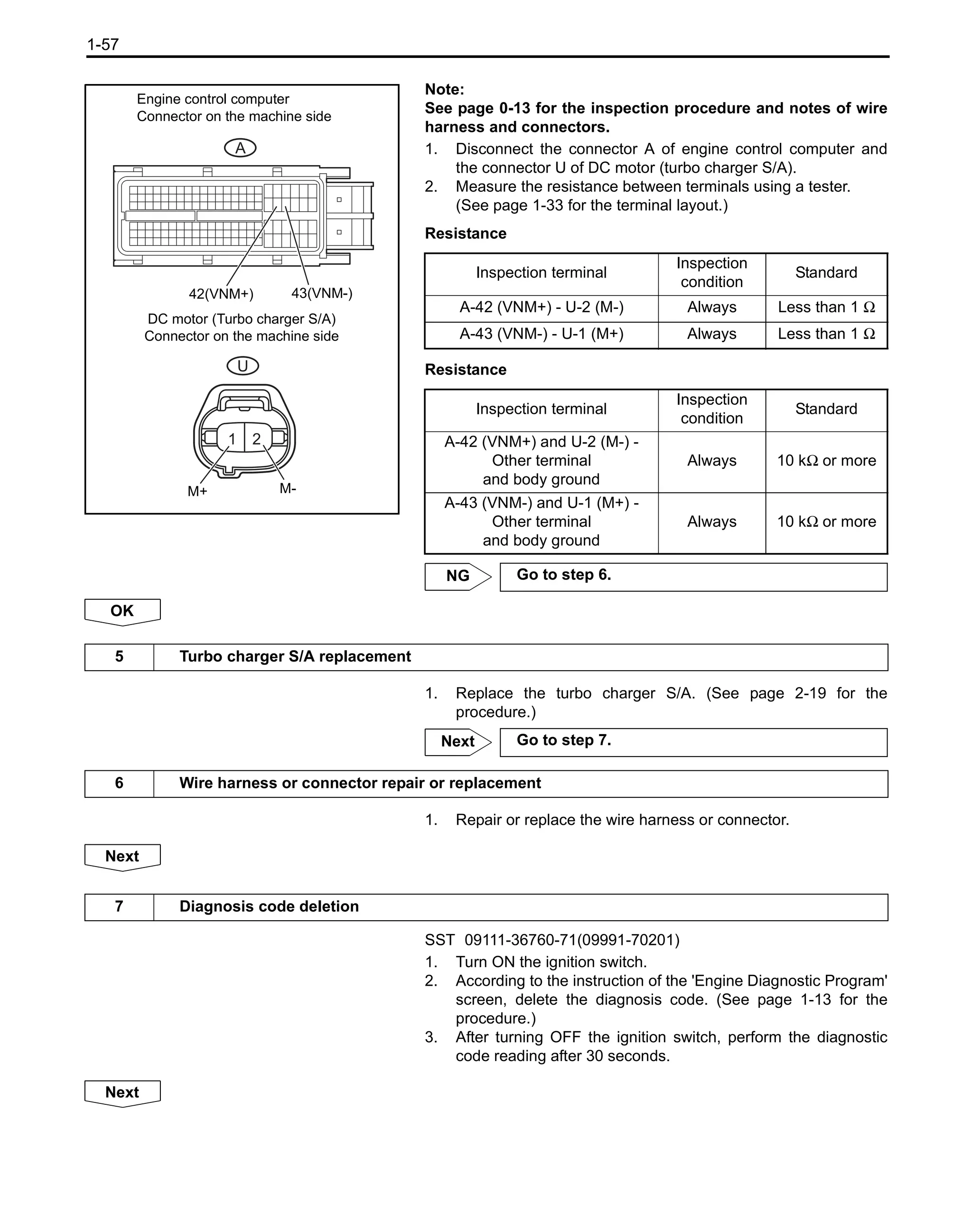
![1-58
SST 09111-36760-71(09991-70201)
1. Turn ON the ignition switch.
2. Press [Active test] select [Activate the VN Turbo Open] on
the 'Engine Diagnostic Program'.
3. Perform the active test and keep the open (fully opened) and
OFF (fully closed) states for 5 seconds or more.
4. According to the instruction of the 'Engine Diagnostic Program'
screen, check that no diagnosis code is output. (See page 1-
13 for the procedure.)
Next
8 Diagnosis code reading
End
1KD_RM.book 58 ページ 2013年9月27日 金曜日 午後12時47分](https://image.slidesharecdn.com/toyota1kdenginerepairmanualtroubles-230327074522-f3541538/75/Toyota-1KD-Engine-Repair-Manual-59-2048.jpg)
![1-59
Circuit description
The inlet air temperature sensor is attached to the intake pipe to measure the intake air temperature. The resistance
value of thermistor included in the inlet air temperature sensor varies with the change in intake air temperature. The
resistance value of thermistor increases as the intake air temperature falls, or decreases as the intake air
temperature rises. The inlet air temperature sensor is connected to the engine control computer, and 5 V power
supply voltage is supplied to the sensor from the THIA terminal of engine control computer via the resistor R. Since
the resistor R and inlet air temperature sensor are connected in series, the resistance value varies with the change in
intake air temperature and also the THIA terminal potential changes. According to this signal, the engine control
computer increases the fuel injection amount or advance the injection timing when the intake air temperature is low
to improve the drivability.
P007C
DTC P007C Charge Air Cooler Temperature Sensor Circuit Low
DTC P007D Charge Air Cooler Temperature Sensor Circuit High
DTC check pattern
DTC detection conditions
1. Diagnosis conditions
2. Abnormal status
3. Abnormal period
4. Others
Inspection position
1 sec. with ignition key switch ON
1. Ignition key switch ON
2. Shorting of inlet air temperature
sensor circuit
3. 0.5 sec. or longer
4. 1 trip
• Wire harness or connector
• Inlet air temperature sensor (for
intake manifold)
• Engine control computer
Resistance
[kΩ]
Temperature [°C]
30
20
10
5
3
2
1
0.5
0.3
0.2
0.1
-20 0 20 40 60 80 100
1KD_RM.book 59 ページ 2013年9月27日 金曜日 午後12時47分](https://image.slidesharecdn.com/toyota1kdenginerepairmanualtroubles-230327074522-f3541538/75/Toyota-1KD-Engine-Repair-Manual-60-2048.jpg)

![1-61
SST 09111-36760-71(09991-70201)
1. Turn the ignition key switch ON and read [Intake Air Temp
(Turbo)] displayed on the 'Engine Diagnostic Program' while
the engine is stopped.
Result
Note:
*: The result is normal at the moment but should be checked
if the defect reappears.
(See page 1-15 for Inspection of irregular problems)
A
SST(1) 09111-36760-71(09991-70201)
SST(2) 09160-36760-71(09843-18040)
1. Disconnect the connector P of inlet air temperature sensor.
2. Using 'diagnosis check wire No.2', short circuit the terminals
between the terminal 1 and 2 of inlet air temperature sensor
connector of the truck side.
3. Turn the ignition key switch ON.
4. Read [Intake Air Temp (Turbo)] displayed on the 'Engine
Diagnostic Program'.
Standard Display temperature 190 °C (374 °F)
NG
1 'Engine Diagnostic Program' data reading (intake air temperature after turbocharging)
Result Go to
-40 °C (-40 °F) (disconnection) A
190 °C (374 °F) (short circuit) B
Same as temperature around intake manifold* C
B Go to step 4.
C Go to step 9.
2 'Engine Diagnostic Program' data reading (wire harness disconnection check)
1 2
P
Inlet air temperature
sensor (for intake manifold)
Connector on the machine side
Inlet air
temperature
Sensor
Engine
control
Computer
OK Go to step 7.
1KD_RM.book 61 ページ 2013年9月27日 金曜日 午後12時47分](https://image.slidesharecdn.com/toyota1kdenginerepairmanualtroubles-230327074522-f3541538/75/Toyota-1KD-Engine-Repair-Manual-62-2048.jpg)
![1-62
Note:
See page 0-13 for the inspection procedure and notes of wire
harness and connectors.
1. Disconnect the connector A of engine control computer and
the connector P of inlet air temperature sensor.
2. Measure the resistance between terminals using a tester.
(See page 1-33 for the terminal layout.)
Resistance
Resistance
SST 09111-36760-71(09991-70201)
1. Disconnect the inlet air temperature sensor connector.
2. Turn the ignition key switch ON.
3. Read [Intake Air Temp (Turbo)] displayed on the 'Engine
Diagnostic Program'
Standard Display temperature -40 °C (-40 °F)
NG
Note:
See page 0-13 for the inspection procedure and notes of wire
harness and connectors.
3
Wire harness and connector inspection
(Engine control computer - Inlet air temperature sensor)
1 2
A
P
Inlet air temperature sensor
(for intake manifold)
Connector on the machine side
Engine control computer
Connector on the machine side
113(THIA) 90(ETHI)
Inspection terminal
Inspection
condition
Standard
A-113 (THIA) - P-2 Always Less than 1 Ω
A-90 (ETHI) - P-1 Always Less than 1 Ω
Inspection terminal
Inspection
condition
Standard
A-113 (THIA) or P-2 -
Other terminal
and body ground
Always 10 kΩ or more
A-90 (ETHI) or P-1 -
Other terminal
and body ground
Always 10 kΩ or more
OK Go to step 6.
NG Go to step 8.
4 'Engine Diagnostic Program' data reading (wire harness short circuit check)
Inlet air
temperature
Sensor
Engine control
Computer
THIA
ETHI OK Go to step 7.
5
Wire harness and connector inspection
(Engine control computer - Inlet air temperature sensor)
1KD_RM.book 62 ページ 2013年9月27日 金曜日 午後12時47分](https://image.slidesharecdn.com/toyota1kdenginerepairmanualtroubles-230327074522-f3541538/75/Toyota-1KD-Engine-Repair-Manual-63-2048.jpg)


![1-67
Note:
• Compare [Fuel Press] with [Target Common Rail Pressure] on the data list. Under stable conditions, the
difference between [Fuel Press] and [Target Common Rail Pressure] is 5000 kPa or less.
• If DTC P0087 is stored, the following symptom may occur.
- Black smoke
- Poor drivability
- Insufficient output
- Insufficient output due to acceleration limit caused by activated fail-safe function
• If DTC P0190, P0192 or P0193 is stored, the following symptom may occur.
- Insufficient output due to acceleration limit caused by activated fail-safe function
• If DTC P0190, P0192 or P0193 is stored, [Fuel Press] always shows [Target Common Rail Pressure].
• If the truck runs out of fuel, the engine control computer may detect it as a drop in fuel pressure and DTC
P0190 or P0192 may be stored.
• After checking DTC P0087, P0190, P0191, P0192 or P0193 output, read [Fuel Press] from [Data monitor]
using 'Engine Diagnostic Program'.
Detection overview
• P0087 (constant output from fuel pressure sensor):
- Under normal conditions, the fuel pressure varies by around 1000 to 2000 kPa even in a constant
traveling state. If the fuel pressure does not vary, a diagnosis code is stored. The fuel pressure at idle is
around 30000 to 40000 kPa. The fuel pressure at NMR of engine speed is around 95000 to 115000 kPa.
When a diagnosis code is stored, the engine control computer enters the fail-safe mode and restricts the
engine output. The engine control computer maintains the fail-safe mode until the ignition key switch is
turned OFF.
- The following illustration shows the relation between the engine speed and fuel pressure. When P0087 is
stored, the fuel pressure does not rise with the increase of engine speed.
• P0190, P0192 or P0193 (fuel pressure sensor circuit disconnected or shorted):
A diagnosis code is stored when the fuel pressure sensor output voltage deviates from the standard
range due to disconnection or shorting of the fuel pressure sensor circuit.
When a diagnosis code is stored, the engine control computer enters the fail-safe mode and restricts the
engine output. The engine control computer maintains the fail-safe mode until the ignition key switch is
turned OFF.
Engine speed Fuel pressure
At idle Approx. 30000 to 40000 kPa
NMR (no-load) Approx. 95000 to 115000 kPa
P0087:
Abnormality detection
Fuel pressure
Engine speed
Normal
Abnormal
Time
1KD_RM.book 67 ページ 2013年9月27日 金曜日 午後12時47分](https://image.slidesharecdn.com/toyota1kdenginerepairmanualtroubles-230327074522-f3541538/75/Toyota-1KD-Engine-Repair-Manual-68-2048.jpg)
![1-68
NOTICE:
• Compare [Fuel Press] with [Target Common Rail Pressure] on the data list. Under stable conditions, the
difference between [Fuel Press] and [Target Common Rail Pressure] is 5000 kPa or less.
• If DTC P0087 is stored, the following symptom may occur.
- Black smoke
- Poor drivability
- Insufficient output
- Insufficient output due to acceleration limit caused by activated fail-safe function
• If DTC P0190, P0192 or P0193 is stored, the following symptom may occur.
- Insufficient output due to acceleration limit caused by activated fail-safe function
• If DTC P0190, P0192 or P0193 is stored, [Fuel Press] always shows [Target Common Rail Pressure].
• If the truck runs out of fuel, the engine control computer may detect it as a drop in fuel pressure and DTC
P0190 or P0192 may be stored.
• After checking DTC P0087, P0190, P0191, P0192 or P0193 output, read [Fuel Press] from [Data monitor]
using 'Engine Diagnostic Program'.
Engine speed Fuel pressure
At idle 30000 to 50000 kPa
NMR (no-load) 90000 to 150000 kPa
Detection overview
• P0087 (constant output from fuel pressure sensor):
- Under normal conditions, the fuel pressure varies by around 1000 to 2000 kPa even in a constant
traveling state. If the fuel pressure does not vary, a diagnosis code is stored. The fuel pressure at idle is
around 30000 to 50000 kPa. The fuel pressure at NMR of engine speed is around 90000 to 150000 kPa.
When a diagnosis code is stored, the engine control computer enters the fail-safe mode and restricts the
engine output. The engine control computer maintains the fail-safe mode until the ignition key switch is
turned OFF.
- The following illustration shows the relation between the engine speed and fuel pressure. When P0087
is stored, the fuel pressure does not rise with the increase of engine speed.
P0087:
Abnormality detection
Fuel pressure
Engine speed
Normal
Abnormal
Time
• P0190, P0192 or P0193 (fuel pressure sensor circuit disconnected or shorted):
A diagnosis code is stored when the fuel pressure sensor output voltage deviates from the standard
range due to disconnection or shorting of the fuel pressure sensor circuit.
When a diagnosis code is stored, the engine control computer enters the fail-safe mode and restricts the
engine output. The engine control computer maintains the fail-safe mode until the ignition key switch is
turned OFF.](https://image.slidesharecdn.com/toyota1kdenginerepairmanualtroubles-230327074522-f3541538/75/Toyota-1KD-Engine-Repair-Manual-69-2048.jpg)

![1-70
1. Replace the common rail ASSY.
(See page 3-3 for the procedure.)
Next
1. Perform the air bleeding of fuel system.
Next
SST 09111-36760-71(09991-70201)
1. Turn ON the ignition switch.
2. According to the instruction of the 'Engine Diagnostic Program'
screen, delete the diagnosis code.
(See page 1-13 for the procedure.)
3. After turning OFF the ignition switch, perform the diagnostic
code reading after 30 seconds.
Next
SST 09111-36760-71(09991-70201)
1. Start the engine.
2. After running at idle for 60 seconds, perform racing from idle to
NMR for 30 seconds.
3. According to the instruction of the 'Engine Diagnostic Program'
screen, press [Trouble Code]
4. Enter P0087, P0190, P0192 or P0193 on the next screen and
confirm the normal state.
Result
Note:
If the diagnosis result check is in process or diagnosis cannot
be made, perform racing again from idle to NMR for 30
seconds.
A
4 Common rail ASSY replacement
5 Air bleeding of the fuel system
6 Diagnosis code deletion
7 Diagnosis code reading
Tester item Result Go to
Diagnosis result
P0087, P0190, P0192 or P0193
is output.
A
Normal B
Abnormal A
B End
1KD_RM.book 70 ページ 2013年9月27日 金曜日 午後12時47分](https://image.slidesharecdn.com/toyota1kdenginerepairmanualtroubles-230327074522-f3541538/75/Toyota-1KD-Engine-Repair-Manual-71-2048.jpg)
![1-71
1. Replace the engine control computer.
1. Repair or replace the wire harness or connector.
Next
SST 09111-36760-71(09991-70201)
1. Turn ON the ignition switch.
2. According to the instruction of the 'Engine Diagnostic Program'
screen, delete the diagnosis code. (See page 1-13 for the
procedure.)
3. After turning OFF the ignition switch, perform the diagnostic
code reading after 30 seconds.
Next
SST 09111-36760-71(09991-70201)
1. Start the engine.
2. After running at idle for 60 seconds, perform racing from idle to
NMR for 30 seconds.
3. According to the instruction of the 'Engine Diagnostic Program'
screen, press [Trouble Code].
(See page 1-13 for the procedure.)
Note:
If the diagnosis result check is in process or diagnosis cannot
be made, perform racing again from idle to NMR for 30
seconds.
Next
8 Engine control computer replacement
Next Go to step 10.
9 Wire harness or connector repair or replacement
10 Diagnosis code deletion
11 Diagnosis code reading
End
1KD_RM.book 71 ページ 2013年9月27日 金曜日 午後12時47分](https://image.slidesharecdn.com/toyota1kdenginerepairmanualtroubles-230327074522-f3541538/75/Toyota-1KD-Engine-Repair-Manual-72-2048.jpg)
![1-72
Circuit description
The supply pump ASSY is a single type pump having a circuit suitable for suctioning of fuel and force feed processes
that realize a force feed of fuel at high pressure and reduction of drive torque. This circuit controls the suction control
valve ASSY that performs suctioning of fuel by plunger in the suction process.
When this DTC is output, the engine control computer enters the fail-safe mode and restricts the engine output. The
engine control computer maintains the fail-safe mode until the ignition key switch is turned OFF.
P0088
Related Data List
Note:
• When DTC P0088 is output, check [Fuel Press] in the data list using 'Engine Diagnostic Program'.
Reference value
• Check the freeze frame data of [Fuel Press], [Target Common Rail Pressure] and [Target Pump SCV
Current] using 'Engine Diagnostic Program'.
DTC P0088 Fuel Rail / System Pressure - Too High
DTC check pattern
DTC detection conditions
1. Diagnosis conditions
2. Abnormal status
3. Abnormal period
4. Others
Inspection position
After running at idle for 60 seconds,
perform racing from idle to NMR for
30 seconds.
1. Ignition key switch ON
2. Rail pressure is 250000 kPa or
more
3. -
4. 1 trip
• Common rail ASSY (fuel pressure
sensor)
• Suction control valve ASSY
• Fuel pressure sensor circuit dis-
connection
• Disconnection or shorting of suc-
tion control valve ASSY circuit
• Engine control computer
DTC No. Data list
P0088
• Fuel pressure
• Common rail target fuel pressure
• Target pump current
Engine speed Fuel pressure
At idle Approx. 30000 to 40000 kPa
NMR (no-load) Approx. 90000 to 150000 kPa
1KD_RM.book 72 ページ 2013年9月27日 金曜日 午後12時47分](https://image.slidesharecdn.com/toyota1kdenginerepairmanualtroubles-230327074522-f3541538/75/Toyota-1KD-Engine-Repair-Manual-73-2048.jpg)
![1-73
DTC P0088 Fuel Rail / System Pressure - Too High
Circuit description
The supply pump ASSY is a single type pump having a circuit suitable for suctioning of fuel and force feed processes
that realize a force feed of fuel at high pressure and reduction of drive torque. This circuit controls the suction control
valve ASSY that performs suctioning of fuel by plunger in the suction process.
When this DTC is output, the engine control computer enters the fail-safe mode and restricts the engine output. The
engine control computer maintains the fail-safe mode until the ignition key switch is turned OFF.
P0088
DTC check pattern
DTC detection conditions
1. Diagnosis conditions
2. Abnormal status
3. Abnormal period
4. Others
Inspection position
After running at idle for 60 seconds,
perform racing from idle to NMR for
30 seconds.
1.Ignition key switch ON
2.Rail pressure is 250000 kPa or
more
3.-
4.1 trip
Common rail ASSY (fuel pressure
sensor)
Suction control valve ASSY
Fuel pressure sensor circuit discon-
nection
Disconnection or shorting of suction
control valve ASSY circuit
Engine control computer
Related Data List
DTC No. Data list
P0088
• Fuel pressure
• Common rail target fuel pressure
• Target pump current
NOTICE:
• When DTC P0088 is output, check [Fuel Press] in the data list using 'Engine Diagnostic Program'.
Reference value
Engine speed Fuel pressure
At idle 30000 to 50000 kPa
NMR (no-load) 90000 to 150000 kPa
• Check the freeze frame data of [Fuel Press], [Target Common Rail Pressure] and [Target Pump SCV
Current] using 'Engine Diagnostic Program'.](https://image.slidesharecdn.com/toyota1kdenginerepairmanualtroubles-230327074522-f3541538/75/Toyota-1KD-Engine-Repair-Manual-74-2048.jpg)
![1-74
Result
Note:
Freeze frame data could be below 250000kPa depend on the
timing to detect the data.
A
SST 09111-36760-71(09991-70201)
1. Turn the ignition key switch ON .
2. According to the instruction of the 'Engine Diagnostic Program'
screen, press [Data monitor] and monitor [Fuel Press].
3. Start up the engine.
4. Excite the wire harness between the sensor and engine
control computer to see if it causes the fuel pressure value to
vary or the engine check indicator to light up.
Note:
Delete a diagnosis code if it has been detected.
Standard Fuel pressure value does not fluctuate due to
excitation and the engine check indicator does
not light.
Result
Result Go to
[Fuel press] values of the 3rd and 4th time-series freeze frame data are 250000 kPa or more. B
Other than the above A
B Go to step 4.
3 Engine control computer inspection (fuel pressure sensor output voltage)
Excitation method (reference):
Engine wire
Engine wire Fuel pressure sensor
(common rail ASSY)
Wire to wire Engine control
Computer
Result Go to
Fuel pressure value fluctuates due to excitation or the engine check indicator lights up. B
Fuel pressure value does not fluctuate due to excitation and the engine check indicator does not
light.
A
1KD_RM.book 74 ページ 2013年9月27日 金曜日 午後12時47分](https://image.slidesharecdn.com/toyota1kdenginerepairmanualtroubles-230327074522-f3541538/75/Toyota-1KD-Engine-Repair-Manual-75-2048.jpg)

![1-76
SST 09111-36760-71(09991-70201)
1. Turn the ignition key switch ON.
2. press [Trouble Code] on the 'Engine Diagnostic Program' and
delete the detected diagnosis code.
3. Perform "Initializing the supply pump ASSY leaned value".
Note:
• Clear the diagnosis code before performing the learned
value initialization.
• See page 1-16 for the procedure of "Initializing the supply
pump ASSY leaned value".
Next
SST 09111-36760-71(09991-70201)
1. Turn ON the ignition switch.
2. According to the instruction of the 'Engine Diagnostic Program'
screen, delete the diagnosis code.
(See page 1-13 for the procedure.)
3. After turning OFF the ignition switch, perform the diagnostic
code reading after 30 seconds.
Next
SST 09111-36760-71(09991-70201)
1. Start the engine.
2. After running at idle for 60 seconds, perform racing from idle to
NMR for 30 seconds.
3. According to the instruction of the 'Engine Diagnostic Program'
screen, press [Trouble Code].
(See page 1-13 for the procedure.)
Result
Note:
If the diagnosis result check is in process or diagnosis cannot
be made, perform racing again from idle to NMR for 30
seconds.
A
1. Replace the engine control computer.
7 Supply pump learned value initialization
8 Diagnosis code deletion
9 Diagnosis code reading
Tester item Result Go to
Diagnosis result
P0088 is output. A
Normal B
Abnormal A
B End
10 Engine control computer replacement
Next Go to step 15.
1KD_RM.book 76 ページ 2013年9月27日 金曜日 午後12時47分](https://image.slidesharecdn.com/toyota1kdenginerepairmanualtroubles-230327074522-f3541538/75/Toyota-1KD-Engine-Repair-Manual-77-2048.jpg)
![1-77
1. Repair or replace the wire harness or connector.
Next
SST 09111-36760-71(09991-70201)
1. Turn the ignition key switch ON.
2. According to the instruction of the 'Engine Diagnostic Program'
screen, press [Data monitor] and monitor [Fuel Press].
3. Start up the engine.
4. Excite the wire harness between the sensor and engine
control computer to see if it causes the fuel pressure value to
vary or the engine check indicator to light up.
Note:
Delete a diagnosis code if it has been detected.
Standard Fuel pressure value does not fluctuate due to
excitation and the engine check indicator does
not light.
Result
A
1. Replace the common rail ASSY.
(See page 3-3 for the procedure.)
Next
1. Perform the air bleeding of fuel system.
Next
SST 09111-36760-71(09991-70201)
1. Turn ON the ignition switch.
2. According to the instruction of the 'Engine Diagnostic Program'
screen, delete the diagnosis code. (See page 1-13 for the
procedure.)
3. After turning OFF the ignition switch, perform the diagnostic
code reading after 30 seconds.
Next
11 Wire harness or connector repair or replacement
12 Engine control computer inspection (fuel pressure sensor output voltage)
Result Go to
Fuel pressure value fluctuates due to excitation or the engine check indicator lights up. A
Fuel pressure value does not fluctuate due to excitation and the engine check indicator does not light. B
B Go to step 15.
13 Common rail ASSY replacement
14 Air bleeding of the fuel system
15 Diagnosis code deletion
1KD_RM.book 77 ページ 2013年9月27日 金曜日 午後12時47分](https://image.slidesharecdn.com/toyota1kdenginerepairmanualtroubles-230327074522-f3541538/75/Toyota-1KD-Engine-Repair-Manual-78-2048.jpg)
![1-78
SST 09111-36760-71(09991-70201)
1. Start the engine.
2. After running at idle for 60 seconds, perform racing from idle to
NMR for 30 seconds.
3. According to the instruction of the 'Engine Diagnostic Program'
screen, press [Trouble Code].
(See page 1-13 for the procedure.)
Note:
If the diagnosis result check is in process or diagnosis cannot
be made, perform racing again from idle to NMR for 30
seconds.
Next
16 Diagnosis code reading
End
1KD_RM.book 78 ページ 2013年9月27日 金曜日 午後12時47分](https://image.slidesharecdn.com/toyota1kdenginerepairmanualtroubles-230327074522-f3541538/75/Toyota-1KD-Engine-Repair-Manual-79-2048.jpg)
![1-79
Circuit description
The fuel pressure sensor is attached to the common rail ASSY to output the fuel pressure after converting it into an
electric signal to the engine control computer. The engine control computer controls the supply pump ASSY (intake
adjustment valve) according to the signal sent from the fuel pressure sensor to maintain the target fuel pressure in
the common rail ASSY.
This diagnosis code indicates a fuel leakage in the high pressure area within the common rail system. After the
engine is started, the engine control computer monitors the fuel pressure within the common rail constantly. The
engine control computer stores this diagnosis code when the fuel pressure drops significantly at fuel injection.
In the common rail system, high pressure fuel is constantly supplied to the supply pump ASSY, common rail ASSY,
injector ASSY and high pressure area within the pipe. The engine control computer adjusts the aperture of the
suction control valve ASSY to maintain the target fuel pressure.
When this diagnosis code is stored, the engine control computer enters the fail-safe mode. In the fail-safe mode, the
engine will be stopped eventually by temporary stop of fuel injection and operation of supply pump ASSY; however,
retreat traveling may be allowed for 1 minute before the engine is stopped. The engine control computer maintains
the fail-safe mode until the ignition key switch is turned OFF.
P0093
Related Data List
Note:
When DTC P0093 is output, check [Fuel Press] in the data list using 'Engine Diagnostic Program'.
Reference value
Circuit diagram
See page 1-123 for P0201 circuit diagram.
See page 1-68 for P0087 circuit diagram.
DTC P0093 Fuel System Leak Detected - Large Leak
DTC check pattern
DTC detection conditions
1. Diagnosis conditions
2. Abnormal status
3. Abnormal period
4. Others
Inspection position
Start up and warm up the engine.
Keep the accelerator pedal fully
open for 5 seconds and then release
the pedal. (*A)
Make the accelerator pedal fully
open and release the pedal when
NMR is reached. (*B)
Perform above (*A) and (*B) 5 times.
1. Engine speed 650 r/min or more
2. Fuel pressure drop before/after
fuel injection is larger than thresh-
old
3. -
4. 1 trip
• Common rail ASSY
(fuel pressure sensor)
• Injector ASSY
• Fuel temperature sensor
• Crank position sensor
• High pressure fuel pipe
• Disconnection or shorting of injec-
tor driver wiring
• Disconnection or shorting of injec-
tor circuit
• Fuel filter element ASSY
• Injector driver
• Engine control computer
DTC No. Data list
P0093
• Fuel pressure
• Common rail target fuel pressure
Engine speed Fuel pressure
At idle Approx. 30000 to 40000 kPa
NMR (no-load) Approx. 90000 to 150000 kPa
1KD_RM.book 79 ページ 2013年9月27日 金曜日 午後12時47分](https://image.slidesharecdn.com/toyota1kdenginerepairmanualtroubles-230327074522-f3541538/75/Toyota-1KD-Engine-Repair-Manual-80-2048.jpg)
![1-80
DTC P0093 Fuel System Leak Detected - Large Leak
Circuit description
The fuel pressure sensor is attached to the common rail ASSY to output the fuel pressure after converting it into an
electric signal to the engine control computer. The engine control computer controls the supply pump ASSY (intake
adjustment valve) according to the signal sent from the fuel pressure sensor to maintain the target fuel pressure in
the common rail ASSY.
This diagnosis code indicates a fuel leakage in the high pressure area within the common rail system. After the engine
is started, the engine control computer monitors the fuel pressure within the common rail constantly. The engine
control computer stores this diagnosis code when the fuel pressure drops significantly at fuel injection.
In the common rail system, high pressure fuel is constantly supplied to the supply pump ASSY, common rail ASSY,
injector ASSY and high pressure area within the pipe. The engine control computer adjusts the aperture of the
suction control valve ASSY to maintain the target fuel pressure.
When this diagnosis code is stored, the engine control computer enters the fail-safe mode. In the fail-safe mode, the
engine will be stopped eventually by temporary stop of fuel injection and operation of supply pump ASSY; however,
retreat traveling may be allowed for 1 minute before the engine is stopped. The engine control computer maintains
the fail-safe mode until the ignition key switch is turned OFF.
P0093
DTC check pattern
DTC detection conditions
1. Diagnosis conditions
2. Abnormal status
3. Abnormal period
4. Others
Inspection position
Start up and warm up the engine.
Keep the accelerator pedal fully
open for 5 seconds and then release
the pedal. (*A)
Make the accelerator pedal fully
open and release the pedal when
NMR is reached. (*B)
Perform above (*A) and (*B) 5 times.
1. Engine speed 650 r/min or more
2. Fuel pressure drop before/after
fuel injection is larger than thresh-
old
3. Specified number of times
4. 1 trip
• Common rail ASSY
(fuel pressure sensor)
• Injector ASSY
• Fuel temperature sensor
• Crank position sensor
• High pressure fuel pipe
• Disconnection or shorting of injec-
tor driver wiring
• Disconnection or shorting of injec-
tor circuit
• Fuel filter element ASSY
• Injector driver
• Engine control computer
Related Data List
DTC No. Data list
P0093
• Fuel pressure
• Common rail target fuel pressure
NOTICE:
When DTC P0093 is output, check [Fuel Press] in the data list using 'Engine Diagnostic Program'.
Reference value
Engine speed Fuel pressure
At idle 30000 to 50000 kPa
NMR (no-load) 90000 to 150000 kPa
Circuit diagram
See page 1-124 for P0201 circuit diagram.
See page 1-69 for P0087 circuit diagram.](https://image.slidesharecdn.com/toyota1kdenginerepairmanualtroubles-230327074522-f3541538/75/Toyota-1KD-Engine-Repair-Manual-81-2048.jpg)
![1-81
1. Add the fuel.
Next
SST 09111-36760-71(09991-70201)
1. Perform air bleeding of the fuel system using the priming pump
located in the fuel filter cap ASSY. Pump it continuously until
the movement of priming pump knob becomes stiff.
Caution:
• Priming pump operation speed: 2 times/sec. or less
• Operate the priming pump with full stroke.
• The priming pump becomes stiff when the pressure at the
entrance of supply pump ASSY becomes saturated.
• If pumping is stopped during air bleeding, the fuel in the
pipe may return to the tank. Keep pumping until the priming
pump becomes stiff.
• If the priming pump does not become stiff after 200 times or
more of continuous pumping, leakage from the pipe
between the fuel tank and fuel filter or running out of gas
may have occurred.
• If a large amount of air is left in the fuel system, the
common rail fuel pressure cannot be raised to the normal
use level and thus the engine cannot be started.
2. Start up the engine.
Caution:
• If a large amount of air is left in the fuel system, it may take
10 seconds or more to start up the engine.
• Do not turn the starter ON continuously for 30 seconds or
more.
• Be careful of running out of battery. (Use a fully charged
battery.)
3. Turn the ignition key switch OFF.
4. Turn the ignition key switch ON.
5. Press [Trouble Code] on the 'Engine Diagnostic Program' and
delete the detected diagnosis code.
6. Implement the fuel system check (fuel system parts
replacement). (See page 1-16 for the procedure.)
4 Refuel
5 Diagnosis code reading
Fuel system check
1st time 2nd time 5th time
3 min idle
Time
ON
OFF
1KD_RM.book 81 ページ 2013年9月27日 金曜日 午後12時47分](https://image.slidesharecdn.com/toyota1kdenginerepairmanualtroubles-230327074522-f3541538/75/Toyota-1KD-Engine-Repair-Manual-82-2048.jpg)
![1-82
7. Press [Trouble Code] on the 'Engine Diagnostic Program' and
read the detected diagnosis code.
(1) When no diagnosis code is output, air bleeding is
completed.
(2) Perform the following work if a diagnosis code is output.
8. Implement the fuel system check (fuel system parts
replacement). (See page 1-16 for the procedure.)
9. Press [Trouble Code] and [Clear] on the 'Engine Diagnostic
Program' and delete the detected diagnosis code.
10. Start up and warm up the engine.
11. Keep the accelerator pedal fully open for 5 seconds and then
release the pedal. (*E)
12. Make the accelerator pedal fully open and release the pedal
when NMR is reached. (*F)
13. Perform above (*E) and (*F) 5 times.
14. Press [Trouble Code] on the 'Engine Diagnostic Program' and
read the detected diagnosis code.
Result
A
Result Go to
Diagnosis code is output. A
Diagnosis code is not output. B
Fuel pressure
Engine speed
Accelerator pedal
Full open
Full open
5 sec. Time
100
0
0
MPa
NMR
*E *F
Repeat *
E and *
F 5 times.
B Diagnosis code is detected due to running out of
fuel, not failure of parts.
1KD_RM.book 82 ページ 2013年9月27日 金曜日 午後12時47分](https://image.slidesharecdn.com/toyota1kdenginerepairmanualtroubles-230327074522-f3541538/75/Toyota-1KD-Engine-Repair-Manual-83-2048.jpg)
![1-83
SST 09111-36760-71(09991-70201)
1. Turn the ignition key switch ON.
2. According to the instruction of the 'Engine Diagnostic Program'
screen, press [Data monitor] and monitor [Fuel Press].
3. Start up the engine.
4. Check [Fuel Press] value in cranking and idling.
Result
A
1. Clean the fuel filter case sub ASSY and replace the fuel filter
element ASSY.
Note:
If fuel filter element ASSY is replaced and installed while
foreign bodies are still left in the fuel filter case sub ASSY, the
injector may not function properly. Therefore, when replacing
the fuel filter element ASSY, make sure to clean inside the fuel
filter case sub ASSY.
Next
SST 09111-36760-71(09991-70201)
1. Perform air bleeding of the fuel system using the priming pump
located in the fuel filter cap ASSY. Pump it continuously until
the movement of priming pump knob becomes stiff.
Caution:
• Priming pump operation speed: 2 times/sec. or less
• Operate the priming pump with full stroke.
• The priming pump becomes stiff when the pressure at the
entrance of supply pump ASSY becomes saturated.
• If pumping is stopped during air bleeding, the fuel in the
pipe may return to the tank. Keep pumping until the priming
pump becomes stiff.
• If the priming pump does not become stiff after 200 times or
more of continuous pumping, leakage from the pipe
between the fuel tank and fuel filter or running out of gas
may have occurred.
• If a large amount of air is left in the fuel system, the
common rail fuel pressure cannot be raised to the normal
use level and thus the engine cannot be started.
6 'Engine Diagnostic Program' data reading (fuel pressure)
Result Go to
Engine does not start, or engine starts but [Fuel Press] value 2 seconds after switching of starter sig-
nal from OFF to ON is less than 20000 kPa.
B
Other than the above A
B Go to step 12.
7 Fuel filter element ASSY replacement (fuel filter case sub ASSY cleaning)
8 Air bleeding of the fuel system
1KD_RM.book 83 ページ 2013年9月27日 金曜日 午後12時47分](https://image.slidesharecdn.com/toyota1kdenginerepairmanualtroubles-230327074522-f3541538/75/Toyota-1KD-Engine-Repair-Manual-84-2048.jpg)
![1-84
2. Start up the engine.
Caution:
• If a large amount of air is left in the fuel system, it may take
10 seconds or more to start up the engine.
• Do not turn the starter ON continuously for 30 seconds or
more.
• Be careful of running out of battery. (Use a fully charged
battery.)
3. Turn the ignition key switch OFF.
4. Turn the ignition key switch ON.
5. Press [Trouble Code] on the 'Engine Diagnostic Program' and
delete the detected diagnosis code.
6. Start up the engine. (*A)
7. Press [Utillity] [Fuel System Check] on the 'Engine
Diagnostic Program'. (*B)
8. Implement the fuel system check (fuel system parts
replacement). (See page 1-16 for the procedure.)
9. Press [Trouble Code] on the 'Engine Diagnostic Program' and
read the detected diagnosis code.
(1) When no diagnosis code is output, air bleeding is
completed.
(2) Perform the following work if a diagnosis code is output.
10. Implement the fuel system check (fuel system parts
replacement).
(See page 1-16 for the procedure.)
Next
1. Implement the fuel system check.
(See page 1-16 for the procedure.)
2. Measure the difference between the [Fuel Press] and [Target
Common Rail Pressure] obtained in the fuel system check.
2nd time 5th time
10 sec.
Time
ON
OFF
Fuel system check
1st time
3 min idle
9 Work support implementation (Fuel system check / fuel system parts replacement)
1KD_RM.book 84 ページ 2013年9月27日 金曜日 午後12時47分](https://image.slidesharecdn.com/toyota1kdenginerepairmanualtroubles-230327074522-f3541538/75/Toyota-1KD-Engine-Repair-Manual-85-2048.jpg)
![1-85
Standard Difference between the target fuel pressure and
the actual fuel pressure two seconds after the
start of fuel system check is less than 10000
kPa.
Note:
• [Target Common Rail Pressure] indicates the target control
fuel pressure of the engine control computer.
• [Fuel Press] indicates the actual fuel pressure in the
common rail.
• When the suction control valve ASSY installed in the supply
pump ASSY is defective, the actual fuel pressure changes
as fuel pressure under the defective conditions in the
illustration.
• Pressure limiter functions to release fuel pressure when the
internal pressure of common rail becomes abnormally high.
Result
A
Engine speed
Fuel system check
Fuel pressure
Check start Check stop
Fuel pressure
under normal
conditions Target fuel pressure
Below
10000 kPa
2 sec.
Time
Fuel pressure
under abnormal
conditions
Fuel pressure when the pressure limiter is defective
2800
1400
ON
OFF
rpm
Result Go to
Difference between the target fuel pressure and the actual fuel pressure two seconds after the start
of active test is less than 10000 kPa
A
Other than the above B
B Go to step 11.
1KD_RM.book 85 ページ 2013年9月27日 金曜日 午後12時47分](https://image.slidesharecdn.com/toyota1kdenginerepairmanualtroubles-230327074522-f3541538/75/Toyota-1KD-Engine-Repair-Manual-86-2048.jpg)
![1-86
SST 09111-36760-71(09991-70201)
Note:
Conduct the following inspection to identify the defective
cylinder.
1. Start the engine.
2. Press [Active test] [Control the Select Cylinder Fuel Cut] on
the 'Engine Diagnostic Program'.
3. Perform control the select cylinder fuel cut active test for each
cylinder to identify the defective cylinder.
Note:
• The defective cylinder produces a small change in idle
speed or idle vibration when a fuel cut is performed during
the engine idling.
• With a normal cylinder, when fuel cut is performed, the
engine falls into rough idle.
1. Remove the glow plug ASSY.
(See page 2-10 for the procedure.)
2. Visually check if fuel is attached to the glow plug ASSY.
Result
Note:
• If fuel is attached to the glow plug ASSY, fuel may be
leaking from the injector ASSY. Replace the injector ASSY.
• After replacing the injector ASSY, check that [Fuel Press]
during cranking is within 5000 kPa of [Target Common Rail
Pressure].
• If fuel is attached to the glow plug ASSY, fuel may be mixed
with engine oil. Check the engine oil level and check if the
engine oil smells like gas oil. When the oil level is above
FULL and the engine oil smells like gas oil, replace the
engine oil.
A
10 'Engine Diagnostic Program' active test implementation (control the select cylinder fuel cut)
Next Go to step 12.
11 Injector ASSY inspection (closing failure inspection)
Result Go to
Fuel is attached to the glow plug ASSY. A
Other than the above B
B Go to step 15.
1KD_RM.book 86 ページ 2013年9月27日 金曜日 午後12時47分](https://image.slidesharecdn.com/toyota1kdenginerepairmanualtroubles-230327074522-f3541538/75/Toyota-1KD-Engine-Repair-Manual-87-2048.jpg)
![1-87
1. Replace the injector ASSY of defective cylinder.
(See page 3-6 for the procedure.)
Note:
• For the cylinder, with which the injector is replaced, make
sure to use a new injection pipe.
• After assembling the injection pipe and leakage pipe
temporarily and positioning the injector according to the
repair manual, tighten the injector to the specified torque.
• If not assembled in the proper order, injector may be
misaligned and become deteriorated, possibly causing a
failure.
• When the injector is deteriorated and causes a failure, this
may result in knocking, rough idling, and other problems.
• Misalignment may degrade the seal-ability between the
injector and injection pipe, possibly resulting in fuel
leakage.
OK
1. Perform the air bleeding of fuel system.
Next
1. Implement the writing the injector compensation code
(Write to the input manual compensation codes.).
(See page 1-16 for the procedure.)
SST 09111-36760-71(09991-70201)
1. Turn the ignition key switch ON.
2. Press [Data monitor] and monitor [Engine Speed]
on the 'Engine Diagnostic Program'.
3. Read the value in cranking and idling after engine warm-up.
Result
Note:
The value that corresponds to the actual engine speed should
be displayed constantly.
OK
12 Injector ASSY replacement (defective cylinder)
13 Air bleeding of the fuel system
14 Work support implementation (Writing the injector compensation code)
Next Go to step 25.
15 'Engine Diagnostic Program' data reading (engine speed)
Data list item Engine status Reference
Engine Speed
Cranking 50 to 400 r/min
Idling (after warm-up) 720 to 780 r/min
NG Go to step 19.
1KD_RM.book 87 ページ 2013年9月27日 金曜日 午後12時47分](https://image.slidesharecdn.com/toyota1kdenginerepairmanualtroubles-230327074522-f3541538/75/Toyota-1KD-Engine-Repair-Manual-88-2048.jpg)
![1-88
12 Injector ASSY replacement (defective cylinder)
1. Replace the injector ASSY of defective cylinder.
(See page 3-6 for the procedure.)
NOTICE:
• For the cylinder, with which the injector is replaced, make
sure to use a new injection pipe.
• After assembling the injection pipe and leakage pipe
temporarily and positioning the injector according to the
repair manual, tighten the injector to the specified torque.
• If not assembled in the proper order, injector may be
misaligned and become deteriorated, possibly causing a
failure.
• When the injector is deteriorated and causes a failure, this
may result in knocking, rough idling, and other problems.
• Misalignment may degrade the seal-ability between the
injector and injection pipe, possibly resulting in fuel leakage.
OK
13 Air bleeding of the fuel system
1. Perform the air bleeding of fuel system.
Next
14 Work support implementation (Writing the injector compensation code)
1. Implement the writing the injector compensation code
(Write to the input manual compensation codes.).
(See page 1-17 for the procedure.)
Next Go to step 25.
15 'Engine Diagnostic Program' data reading (engine speed)
Result
SST 09111-36760-71
1. Turn the ignition key switch ON.
2. Press [Data monitor] and monitor [Engine Speed]
on the 'Engine Diagnostic Program'.
3. Read the value in cranking and idling after engine warm-up.
Data list item Engine status Reference
Engine Speed
Cranking 50 to 400 r/min
Idling (after warm-up) Refer to repair manual of the vehicle
NOTICE:
The value that corresponds to the actual engine speed should
be displayed constantly.
NG Go to step 19.
OK](https://image.slidesharecdn.com/toyota1kdenginerepairmanualtroubles-230327074522-f3541538/75/Toyota-1KD-Engine-Repair-Manual-89-2048.jpg)
![1-89
SST 09111-36760-71(09991-70201)
1. Turn the ignition key switch ON.
2. While the engine is stopped, according to the instruction of the
'Engine Diagnostic Program' screen, press [Data monitor] and
read [Fuel Temperature].
Reference [Fuel Temperature] value is roughly the same
as the actual fuel temperature.
Note:
The data monitor [Fuel Temperature] value is roughly the
same as the ambient temperature on the truck that has been
left with the engine stopped overnight.
OK
Note:
See page 1-15 for inspection of irregular problems.
1. Replace the crank position sensor No. 2.
(See page 2-41 for the procedure.)
1. Repair or replace the wire harness or connector.
Next
SST 09111-36760-71(09991-70201)
1. Turn the ignition key switch ON.
2. According to the instruction of the 'Engine Diagnostic Program'
screen, press [Data monitor] and monitor [Fuel Press].
3. Start up the engine.
4. Excite the wire harness between the sensor and engine
control computer to see if it causes the engine check indicator
to light up.
17 Fuel temperature sensor inspection (sensor output)
NG Go to step 24.
18 Inspection of irregular problems
Next Go to step 25.
19 Crank position sensor No. 2 replacement
Next Go to step 25.
20
Wire harness or connector repair/replacement
(Engine control computer - Fuel pressure sensor)
21 Engine control computer inspection (fuel pressure sensor output voltage)
1KD_RM.book 89 ページ 2013年9月27日 金曜日 午後12時47分](https://image.slidesharecdn.com/toyota1kdenginerepairmanualtroubles-230327074522-f3541538/75/Toyota-1KD-Engine-Repair-Manual-90-2048.jpg)

![1-91
SST 09111-36760-71(09991-70201)
1. Turn ON the ignition switch.
2. According to the instruction of the 'Engine Diagnostic Program'
screen, delete the diagnosis code.
(See page 1-13 for the procedure.)
3. After turning OFF the ignition switch, perform the diagnostic
code reading after 30 seconds.
Next
SST 09111-36760-71(09991-70201)
1. Turn the ignition key switch ON.
2. Press [Trouble Code] on the 'Engine Diagnostic Program' and
delete the detected diagnosis code.
3. Start up and warm up the engine.
4. Keep the accelerator pedal fully open for 5 seconds and then
release the pedal. (*A)
5. Make the accelerator pedal fully open and release the pedal
when NMR is reached. (*B)
6. Perform above (*A) and (*B) 5 times.
7. Press [Trouble Code] on the 'Engine Diagnostic Program' and
read the detected diagnosis code.
Standard Diagnosis code is not detected.
Next
25 Diagnosis code deletion
26 Diagnosis code reading
Fuel pressure
Engine speed
Accelerator pedal
Full open
Full open
5 sec. Time
100
0
5000
0
MPa
rpm
*A *B
Repeat *A and *B 5 times.
End
1KD_RM.book 91 ページ 2013年9月27日 金曜日 午後12時47分](https://image.slidesharecdn.com/toyota1kdenginerepairmanualtroubles-230327074522-f3541538/75/Toyota-1KD-Engine-Repair-Manual-92-2048.jpg)
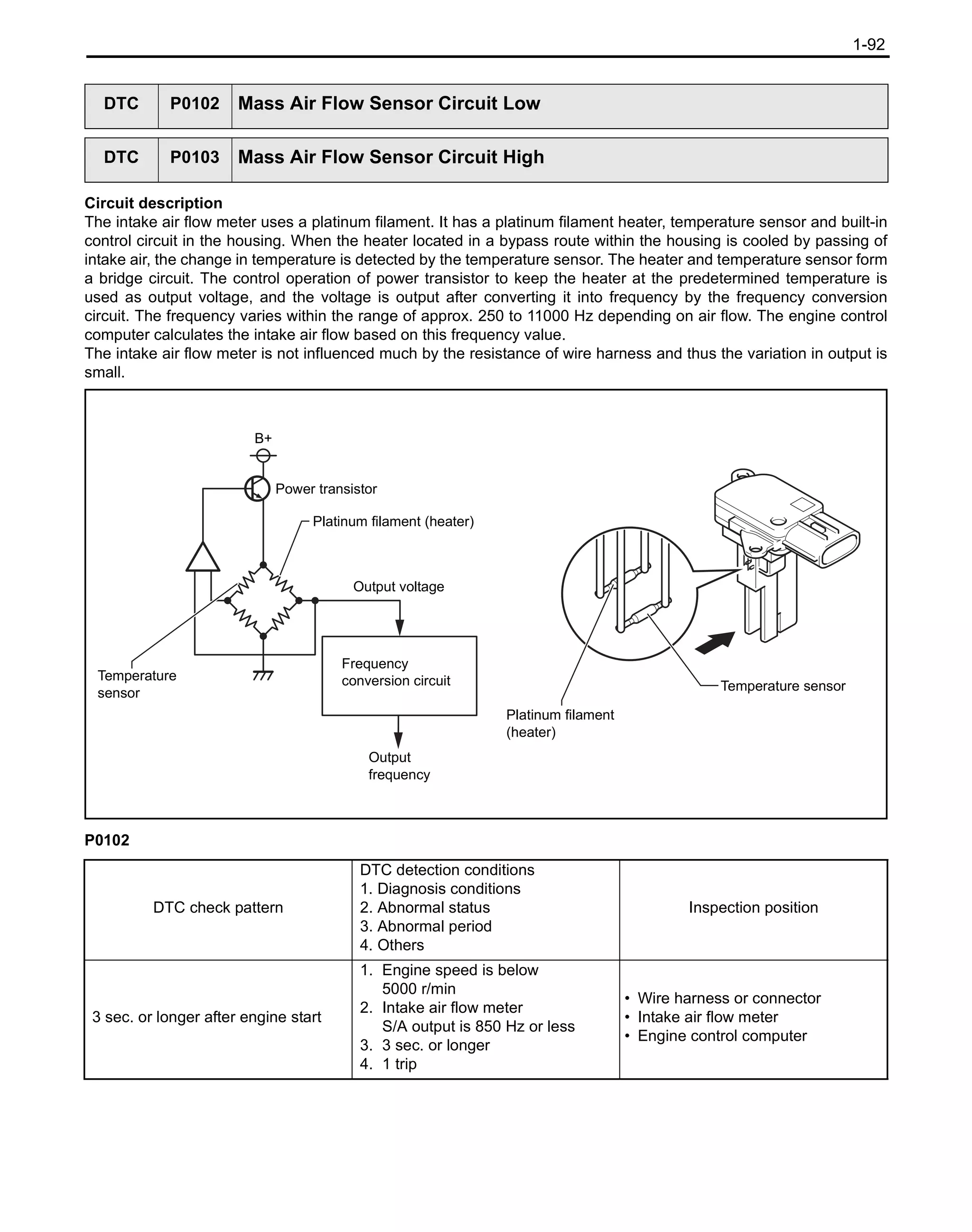
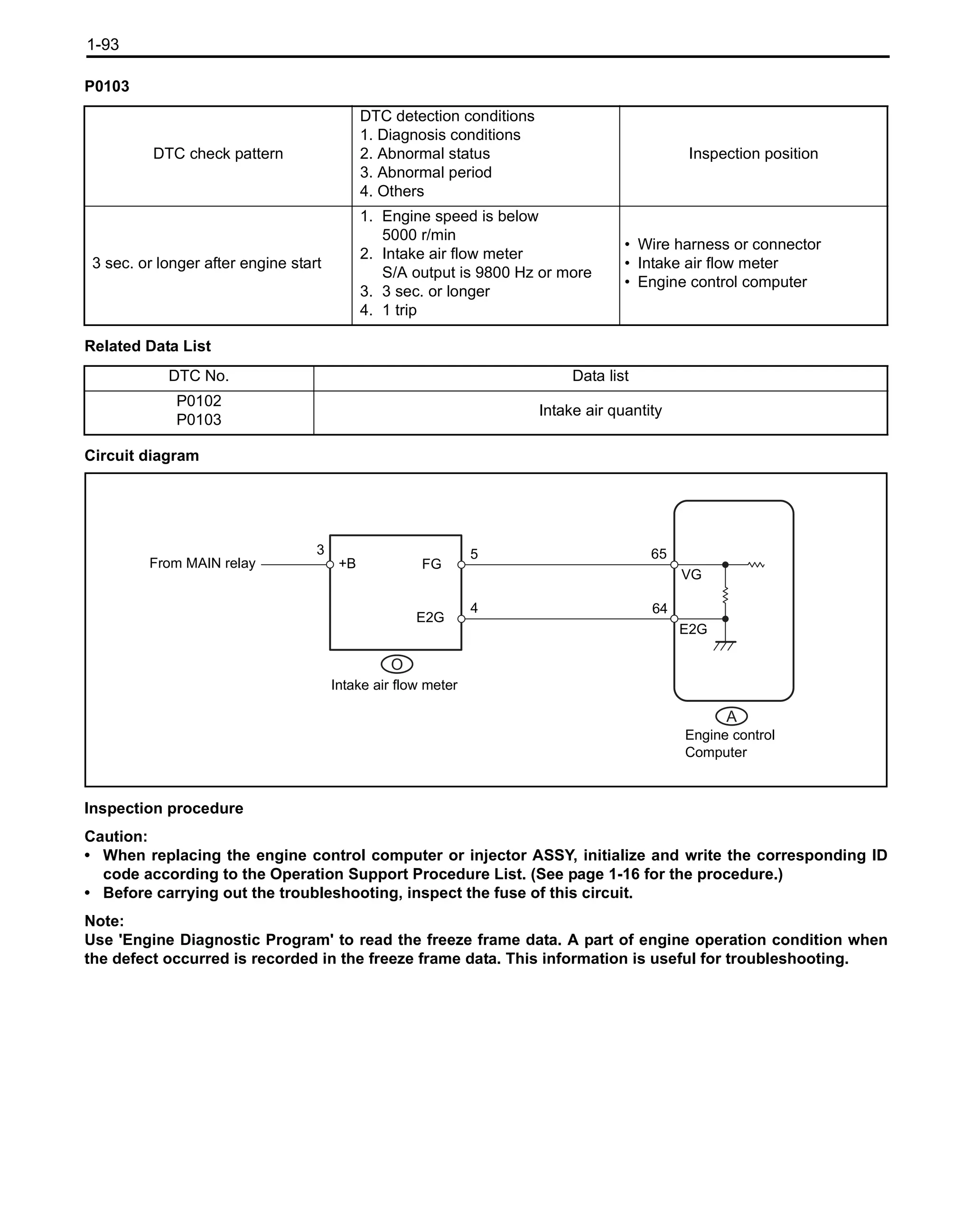


![1-98
Related Data List
Note:
After checking DTC P0107 or P0108 output, read [MAP] on the ECU data monitor screen using 'Engine
Diagnostic Program'.
Circuit diagram
Inspection procedure
Caution:
When replacing the engine control computer or injector ASSY, initialize and write the corresponding ID code
according to the Operation Support Procedure List. (See page 1-15 for the procedure.)
Note:
Use 'Engine Diagnostic Program' to read the freeze frame data. A part of engine operation condition when
the defect occurred is recorded in the freeze frame data. This information is useful for troubleshooting.
DTC No. Data list
P0107
P0108
Intake manifold pressure
Intake manifold absolute pressure Defects
Approx. 15 kPa or less
(113 mmHg)
• Shorting with PIM circuit ground system
• VC circuit disconnection
426 kPa or more
(3200 mmHg)
• Shorting with PIM circuit of VC circuit
• PIM circuit disconnection
• E2 circuit disconnection
A
R
Diesel turbo pressure sensor
(vacuum sensor)
Engine control computer
3
2
1
VC
PIM
E
93
117
72
VCPM
PIM
EPIM
1KD_RM.book 98 ページ 2013年9月27日 金曜日 午後12時47分](https://image.slidesharecdn.com/toyota1kdenginerepairmanualtroubles-230327074522-f3541538/75/Toyota-1KD-Engine-Repair-Manual-99-2048.jpg)
![1-99
SST 09111-36760-71(09991-70201)
1. Turn the ignition key switch ON and according to the
instruction of the 'Engine Diagnostic Program' screen, press
[Data monitor] screen while the engine is stopped, and then
read [MAP].
Standard Same as the atmospheric pressure
Result
Note:
*: The result is normal at the moment but should be checked
if the defect reappears.
(See page 1-15 for Inspection of irregular problems)
A
Note:
See page 0-13 for the inspection procedure and notes of wire
harness and connectors.
1. Disconnect the connector A of engine control computer and
the connector R of diesel turbo pressure sensor.
2. Measure the resistance between terminals using a tester. (See
page 1-33 for the terminal layout.)
Resistance
Resistance
OK
1 'Engine Diagnostic Program' data reading (intake manifold pressure)
Result Go to
Abnormal A
Normal* B
B Go to step 9.
2 Wire harness and connector inspection
(Engine control computer - Diesel turbo pressure sensor)
A
R
1 2 3
Engine control computer
Connector on the machine side
Diesel turbo pressure sensor
Connector on the machine side
72(EPIM) 117(PIM) 93(VCPM)
E PIM
VC
Inspection terminal
Inspection
condition
Standard
A-93 (VCPM) - R-3 (VC) Always Less than 1 Ω
A-117 (PIM) - R-2 (PIM) Always Less than 1 Ω
A-72 (EPIM) - R-1 (E) Always Less than 1 Ω
Inspection terminal
Inspection
condition
Standard
A-93 (VCPM) and R-3 (VC) -
Other terminal and
body ground
Always 10 kΩ or more
A-117 (PIM) and R-2 (PIM) -
Other terminal and
body ground
Always 10 kΩ or more
A-72 (EPIM) and R-1 (E) -
Other terminal
Always 10 kΩ or more
NG Go to step 8.
1KD_RM.book 99 ページ 2013年9月27日 金曜日 午後12時47分](https://image.slidesharecdn.com/toyota1kdenginerepairmanualtroubles-230327074522-f3541538/75/Toyota-1KD-Engine-Repair-Manual-100-2048.jpg)


![1-102
Circuit description
The inlet air temperature sensor is installed in the intake air flow meter S/A to measure the intake air temperature.
The resistance value of thermistor included in the inlet air temperature sensor varies with the change in intake air
temperature. The resistance value of thermistor increases as the intake air temperature falls, or decreases as the
intake air temperature rises. The inlet air temperature sensor is connected to the engine control computer, and 5 V
power supply voltage is supplied to the sensor from the THA terminal of engine control computer via the resistor R.
Since the resistor R and inlet air temperature sensor are connected in series, the resistance value varies with the
change in intake air temperature and also the THA terminal potential changes. According to this signal, the engine
control computer increases the fuel injection amount when cool, in order to improve the drivability.
P-0112
DTC P0112 Intake Air Temperature Sensor Circuit Low
DTC P0113 Intake Air Temperature Sensor Circuit High
DTC check pattern
DTC detection conditions
1. Diagnosis conditions
2. Abnormal status
3. Abnormal period
4. Others
Inspection position
0.5 sec. or longer with ignition key
switch ON
1. Ignition key switch ON
2. Shorting of inlet air temperature
sensor circuit
3. 0.5 sec. or longer
4. 1 trip
• Wire harness or connector
• Intake air flow meter
• Engine control computer
Resistance
[kΩ]
Temperature [°C]
30
20
10
5
3
2
1
0.5
0.3
0.2
0.1
-20 0 20 40 60 80 100
1KD_RM.book 102 ページ 2013年9月27日 金曜日 午後12時47分](https://image.slidesharecdn.com/toyota1kdenginerepairmanualtroubles-230327074522-f3541538/75/Toyota-1KD-Engine-Repair-Manual-103-2048.jpg)

![1-104
SST 09111-36760-71(09991-70201)
1. Turn the ignition key switch ON and read [Intake Air] displayed
on the 'Engine Diagnostic Program' while the engine is
stopped.
Result
Note:
*: The result is normal at the moment but should be checked
if the defect reappears.
(See page 1-15 for Inspection of irregular problems)
A
SST 1 09111-36760-71 (09991-70201)
SST 2 09160-36760-71 (09843-18040)
1. Disconnect the connector O of intake air flow meter S/A.
2. Using "Diagnosis check wire No.2", short circuit the terminals
between the terminal O-1 (THA) and O-2 (E2) of the intake air
flow meter S/A connector of the truck side.
3. Turn the ignition key switch ON.
4. Read [Intake Air] displayed on the 'Engine Diagnostic Program'.
Standard display temperature 140 °C (284 °F)
NG
Note:
See page 0-13 for the inspection procedure and notes of wire
harness and connectors.
1 'Engine Diagnostic Program' data reading (intake air temperature)
Result Go to
-40 °C (-40 °F) (disconnection) A
140 °C (284 °F) (short circuit) B
Same as ambient temperature*
C
B Go to step 4.
C Go to step 9.
2 'Engine Diagnostic Program' data reading (wire harness disconnection check)
1 2 3 4 5
O
Intake air flow meter
Connector on the machine side
E2
THA
OK Go to step 7.
3 Wire harness and connector inspection
(Intake air flow meter S/A - Engine control computer)
1KD_RM.book 104 ページ 2013年9月27日 金曜日 午後12時47分](https://image.slidesharecdn.com/toyota1kdenginerepairmanualtroubles-230327074522-f3541538/75/Toyota-1KD-Engine-Repair-Manual-105-2048.jpg)
![1-105
1. Disconnect the connector A of engine control computer and
the connector O of intake air flow meter S/A.
2. Measure the resistance between terminals using a tester. (See
page 1-33 for the terminal layout.)
Resistance
SST 09111-36760-71(09991-70201)
1. Disconnect the connector of intake air flow meter S/A.
2. Turn the ignition key switch ON.
3. Read [Intake Air] displayed on the 'Engine Diagnostic Program'.
Standard display temperature -40 °C (-40 °F)
NG
Note:
See page 0-13 for the inspection procedure and notes of wire
harness and connectors.
A
O
5
4
3
2
1
Engine control computer
Connector on the machine side
Intake air flow meter
Connector on the machine side
110 (THA) 87 (ETHA)
THA
E2
Inspection terminal
Inspection
condition
Standard
A-110 (THA) - O-1 (THA) Always Less than 1 Ω
A-87 (ETHA) - O-2 (E2) Always Less than 1 Ω
OK Go to step 6.
NG Go to step 8.
4 'Engine Diagnostic Program' data reading (wire harness short circuit check)
OK Go to step 7.
5 Wire harness and connector inspection
(Intake air flow meter S/A - Engine control computer)
1KD_RM.book 105 ページ 2013年9月27日 金曜日 午後12時47分](https://image.slidesharecdn.com/toyota1kdenginerepairmanualtroubles-230327074522-f3541538/75/Toyota-1KD-Engine-Repair-Manual-106-2048.jpg)


![1-109
Note:
When P0115, P0117 and P0118 are stored, the following symptoms may occur.
- Misfire
- Knocking
- Black smoke
- White smoke
- Insufficient output
Circuit diagram
Inspection procedure
Caution:
When replacing the engine control computer or injector ASSY, initialize and write the corresponding ID code
according to the Operation Support Procedure List. (See page 1-16 for the procedure.)
Note:
Use 'Engine Diagnostic Program' to read the freeze frame data. A part of engine operation condition when
the defect occurred is recorded in the freeze frame data. This information is useful for troubleshooting.
SST 09111-36760-71(09991-70201)
1. Turn the ignition key switch ON and read [Coolant Temp]
displayed on the 'Engine Diagnostic Program' while the engine
is stopped.
Result
Note:
*: The result is normal at the moment but should be checked
if the defect reappears.
(See page 1-15 for Inspection of irregular problems)
A
A
Q
Water temperature sensor
Engine control computer
2
1
111
88
THW
ETHW
1 'Engine Diagnostic Program' data reading (engine cooling water temperature)
Result Go to
-40 °C (-40 °F) (disconnection) A
140 °C (284 °F) (short circuit) B
Same as actual water temperature*
C
B Go to step 4.
C Go to step 9.
1KD_RM.book 109 ページ 2013年9月27日 金曜日 午後12時47分](https://image.slidesharecdn.com/toyota1kdenginerepairmanualtroubles-230327074522-f3541538/75/Toyota-1KD-Engine-Repair-Manual-110-2048.jpg)
![1-110
SST 1 09111-36760-71 (09991-70201)
SST 2 09160-36760-71 (09843-18040)
Åv
1. Disconnect the connector Q of water temperature sensor.
2. Using "Diagnosis check wire No.2", short circuit the terminals
between the terminal Q-2 and Q-1 of diesel engine water
temperature connector.
3. Turn the ignition key switch ON.
4. Read [Coolant Temp] displayed on the 'Engine Diagnostic
Program'.
Reference: display temperature 140 °C (284 °F)
Result
B
Note:
See page 0-13 for the inspection procedure and notes of wire
harness and connectors.
1. Disconnect the connector A of engine control computer and
the connector Q of water temperature sensor.
2. Measure the resistance between terminals using a tester. (See
page 1-33 for the terminal layout.)
Resistance
2 'Engine Diagnostic Program' data reading (wire harness disconnection check)
1 2
Q
Water temperature
Sensor
Engine control
Computer
Water temperature sensor
Connector on the machine side
THW
ETHW
Result Go to
Normal A
Abnormal B
A Go to step 7.
3 Wire harness and connector inspection
(Water temperature sensor - Engine control computer)
1 2
A
Q
Engine control computer
Connector on the machine side
Water temperature sensor
Connector on the machine side
111 (THW) 88 (ETHW)
Inspection terminal
Inspection
condition
Standard
A-111 (THW) - Q-2 Always Less than 1 Ω
A-88 (ETHW) - Q-1 Always Less than 1 Ω
OK Go to step 6.
NG Go to step 8.
1KD_RM.book 110 ページ 2013年9月27日 金曜日 午後12時47分](https://image.slidesharecdn.com/toyota1kdenginerepairmanualtroubles-230327074522-f3541538/75/Toyota-1KD-Engine-Repair-Manual-111-2048.jpg)
![1-111
SST 09111-36760-71(09991-70201)
1. Disconnect the connector of water temperature sensor.
2. Turn the ignition key switch ON.
3. Read [Coolant Temp] displayed on the 'Engine Diagnostic
Program'.
Reference display temperature -40 °C (-40 °F)
Result
B
Note:
See page 0-13 for the inspection procedure and notes of wire
harness and connectors.
1. Disconnect the connector A of engine control computer and
the connector Q of water temperature sensor.
2. Measure the resistance between terminals using a tester. (See
page 1-33 for the terminal layout.)
Resistance
OK
1. Replace the engine control computer.
4 'Engine Diagnostic Program' data reading (wire harness short circuit check)
Water temperature
Sensor
Engine control
Computer
THW
ETHW
Result Go to
Normal A
Abnormal B
A Go to step 7.
5 Wire harness and connector inspection
(Water temperature sensor - Engine control computer)
1 2
A
Q
Engine control computer
Connector on the machine side
Water temperature sensor
Connector on the machine side
111 (THW) 88 (ETHW)
Inspection terminal
Inspection
condition
Standard
A-111 (THW) and Q-2 -
Other terminal and
body ground
Always 10 kΩ or more
A-88 (ETHW) and Q-1 -
Other terminal and
body ground
Always 10 kΩ or more
NG Go to step 8.
6 Engine control computer replacement
Next Go to step 9.
1KD_RM.book 111 ページ 2013年9月27日 金曜日 午後12時47分](https://image.slidesharecdn.com/toyota1kdenginerepairmanualtroubles-230327074522-f3541538/75/Toyota-1KD-Engine-Repair-Manual-112-2048.jpg)


![1-114
Note:
When P0180, P0182 and P0183 are stored, the following symptoms may occur.
- Misfire
- Knocking
- Black smoke
- Insufficient output
Circuit diagram
Inspection procedure
Caution:
When replacing the engine control computer or injector ASSY, initialize and write the corresponding ID code
according to the Operation Support Procedure List.
(See page 1-16 for the procedure.)
Note:
Use 'Engine Diagnostic Program' to read the freeze frame data. A part of engine operation condition when
the defect occurred is recorded in the freeze frame data. This information is useful for troubleshooting.
SST 09111-36760-71(09991-70201)
1. Turn the ignition key switch ON.
2. While the engine is stopped, according to the instruction of the
'Engine Diagnostic Program' screen, press [Data monitor] and
read [Fuel Temperature].
Result
Note:
*: The result is normal at the moment but should be checked
if the defect reappears.
(See page 1-15 for Inspection of irregular problems)
A
A
K
Fuel temperature sensor
Engine control computer
2
1
112
89
THF
ETHF
1 'Engine Diagnostic Program' data reading (fuel temperature)
Result Go to
-40 °C (-40 °F) (disconnection) A
140 °C (284 °F) (short circuit) B
Same as actual fuel temperature*
C
B Go to step 4.
C Go to step 10.
1KD_RM.book 114 ページ 2013年9月27日 金曜日 午後12時47分](https://image.slidesharecdn.com/toyota1kdenginerepairmanualtroubles-230327074522-f3541538/75/Toyota-1KD-Engine-Repair-Manual-115-2048.jpg)
![1-115
SST 1 09111-36760-71 (09991-70201)
SST 2 09160-36760-71 (09843-18040)
1. Disconnect the connector K of fuel temperature sensor.
2. Using "Diagnosis check wire No.2", short circuit the terminals
of fuel temperature sensor connector of the truck side.
3. Turn the ignition key switch ON.
4. While the engine is stopped, according to the instruction of the
'Engine Diagnostic Program' screen, press [Data monitor] and
read [Fuel Temperature].
Standard display temperature 140 °C (284 °F) or more
NG
Note:
See page 0-13 for the inspection procedure and notes of wire
harness and connector.
1. Disconnect the connector A of engine control computer and
the connector K of fuel temperature sensor.
2. Measure the resistance between terminals using a tester. (See
page 1-33 for the terminal layout.)
Resistance
SST 09111-36760-71(09991-70201)
1. Disconnect the connector of fuel temperature sensor.
2. Turn the ignition key switch ON.
3. While the engine is stopped, according to the instruction of the
'Engine Diagnostic Program' screen, press [Data monitor] and
read [Fuel Temperature].
Standard display temperature -40 °C (-40 °F)
OK
2 'Engine Diagnostic Program' data reading (wire harness disconnection check)
1 2
K
Fuel temperature sensor
Connector on the machine side
OK Go to step 5.
3 Wire harness and connector inspection
(Engine control computer - Fuel temperature sensor)
1 2
A
K
Fuel temperature sensor
Connector on the machine side
Engine control computer
Connector on the machine side
112 (THF) 89 (ETHF)
Inspection terminal
Inspection
condition
Standard
A-112 (THF) - K-2 Always Less than 1 Ω
A-89 (ETHF) - K-1 Always Less than 1 Ω
OK Go to step 7.
NG Go to step 8.
4 'Engine Diagnostic Program' data reading (wire harness short circuit check)
NG Go to step 6.
1KD_RM.book 115 ページ 2013年9月27日 金曜日 午後12時47分](https://image.slidesharecdn.com/toyota1kdenginerepairmanualtroubles-230327074522-f3541538/75/Toyota-1KD-Engine-Repair-Manual-116-2048.jpg)


![1-125
1. Start up the engine.
Result
Note:
• *1: P062D is stored.
• *1: If the engine does not start due to a failure of injector
driver after deleting DTC of P062D, P062D will not be stored.
When a failure of injector driver prevents the engine from
starting, [Fuel Press] shows a value higher than [Target
Common Rail Pressure].
• *2: P0201, P0202, P0203 or P0204 is stored.
A
Note:
See page 0-13 for the inspection procedure and notes of wire
harness and connectors.
1. Disconnect the connector C of injector driver.
2. Turn the ignition key switch ON.
3. Measure the voltage between terminals using a tester.
Voltage value
OK
Note:
See page 0-13 for the inspection procedure and notes of wire
harness and connectors.
1 Engine start inspection
Result Go to
Engine does not start.*1 A
Engine starts but idles rough.*2 B
Other than the above C
B Go to step 4.
C Inspection of irregular problems
(See page 1-15 for the procedure)
2 Injector driver power supply circuit inspection
1 2 3
4
C
6
5
Injector driver
Connector on the machine side
+B GND
Inspection terminal
Inspection
condition
Reference
C-2 (+B) - C-3 (GND)
Ignition key
switch ON
11 to 14 V
NG Go to step 15.
3 Wire harness and connector inspection (Engine control computer - Injector driver)
1KD_RM.book 125 ページ 2013年9月27日 金曜日 午後12時47分](https://image.slidesharecdn.com/toyota1kdenginerepairmanualtroubles-230327074522-f3541538/75/Toyota-1KD-Engine-Repair-Manual-126-2048.jpg)


![1-131
Circuit description
See page 1-54 for P0046 circuit description.
P0299
Related Data List
Note:
The following symptoms may occur when the variable nozzle is stuck open and DTC P0299 is stored.
• Insufficient output
• Surge or hesitation under light or middle load condition
Circuit diagram
See page 1-123 for P0046 circuit diagram.
Inspection procedure
Caution:
When replacing the engine control computer or injector ASSY, initialize and write the corresponding ID code
according to the Operation Support Procedure List. (See page 1-16 for the procedure.)
Note:
• Use 'Engine Diagnostic Program' to read the freeze frame data. A part of engine operation condition when
the defect occurred is recorded in the freeze frame data. This information is useful for troubleshooting.
• Compare the data lists of [MAP] and [Target Booster Pressure] during acceleration at medium or high
rotation rate to determine the defect condition.
DTC P0299 Turbocharger Underboost
DTC check pattern
DTC detection conditions
1. Diagnosis conditions
2. Abnormal status
3. Abnormal period
4. Others
Inspection position
-
1. After warm-up, engine speed is
800 r/min or more
2. Supercharging pressure deviation
is the specified value or more
3. 80 sec.
4. 1 trip
Turbo charger S/A
Low battery voltage (P0560 detected
simultaneously)
Disconnection of the pipe between
the turbo charger S/A and intake
manifold
Disconnection of the diesel turbo
pressure sensor hose
Diesel turbo pressure sensor
Electric EGR control valve ASSY
Modification or clogging of the intake
and exhaust system
Injection system (reduction of fuel
injection amount)
Engine control computer
DTC No. Data list
P0299
• Target supercharging pressure
• Intake manifold pressure
1KD_RM.book 131 ページ 2013年9月27日 金曜日 午後12時47分](https://image.slidesharecdn.com/toyota1kdenginerepairmanualtroubles-230327074522-f3541538/75/Toyota-1KD-Engine-Repair-Manual-132-2048.jpg)


![1-147
Detection overview
If the EGR valve target opening degree and actual opening degree are different to each other, the engine control
computer detects it as EGR valve abnormality and turns on the engine check indicator.
Note:
• If there is a large volume of carbon deposits on the electric EGR control valve ASSY, the parts related to
the intake manifold, EGR with cooler pipe S/A and exhaust gas system may also have carbon deposits
inside.
• Use 'Engine Diagnostic Program' to read the freeze frame data. A part of engine operation condition when
the defect occurred is recorded in the freeze frame data. This information is useful for troubleshooting.
• Carefully check the [Actual EGR Valve Pos.], [Target EGR Pos.] and [MAF] of the freeze frame data.
Error detection:
Open
EGR valve target opening degree
EGR valve actual opening degree
Abnormality counter
Closed
Open
Closed
Time
Abnormal
(movement defect)
Abnormality
judgment value
Normal
Abnormal (stuck)
Detection of P042E
1KD_RM.book 147 ページ 2013年9月27日 金曜日 午後12時47分](https://image.slidesharecdn.com/toyota1kdenginerepairmanualtroubles-230327074522-f3541538/75/Toyota-1KD-Engine-Repair-Manual-148-2048.jpg)

![1-149
SST 09111-36760-71 (09991-70201)
1. Turn ON the ignition switch.
2. Press [Active test], select [EGR taget opening degree bank1]
on the 'Engine Diagnostic Program'.
3. Select [Target EGR Pos.] and [Actual EGR Valve Pos.] from
the data list item, then press [Start].
4. Implement the active test.
Reference The value of [Actual EGR Valve Pos.] must
follow that of [Target EGR Pos.].
OK
SST 09111-36760-71 (09991-70201)
1. Remove the electric EGR control valve ASSY.
(See page 2-12 for the procedure.)
2. After removing the electric EGR control valve ASSY, connect
the connector.
3. Turn ON the ignition switch.
4. Press [Active test], select [EGR taget opening degree bank1]
on the 'Engine Diagnostic Program'.
5. When performing the active test, check if the valve of the
electric EGR control valve ASSY opens and closes.
Reference The valve opens and closes.
6. Check that the electric EGR control valve ASSY is fully closed.
Reference The electric EGR control valve ASSY is fully
closed.
Note:
• Hold the electric EGR control valve ASSY against the light
to confirm that the valve completely contacts with the valve
seat.
• If light leaks from the valve, the electric EGR control valve
ASSY is not fully closed.
• If there is a large volume of deposits on the electric EGR
control valve ASSY or intake manifold, remove them.
7. Install the electric EGR control valve ASSY.
(See page 2-12 for the procedure.)
NG
1. Replace the electric EGR control valve ASSY.
(See page 2-12 for the procedure.)
Note:
Before replacing the electric EGR control valve ASSY, inspect
the connecting condition of the wire harness and connector. If
abnormal, replace or repair the wire harness or connector.
2 'Engine Diagnostic Program' active test implementation (EGR target opening degree bank 1)
NG Go to step 4.
3 'Engine Diagnostic Program' active test implementation (EGR target opening degree bank 1)
OK Go to step 5.
4 Replacement of electric EGR control valve ASSY
Next Go to step 6.
1KD_RM.book 149 ページ 2013年9月27日 金曜日 午後12時47分](https://image.slidesharecdn.com/toyota1kdenginerepairmanualtroubles-230327074522-f3541538/75/Toyota-1KD-Engine-Repair-Manual-150-2048.jpg)


![1-154
Circuit description
Battery power is constantly supplied to the BATT terminal. It is used for diagnosis code storage and freeze frame
data storage, etc. If an error occurs in the BATT terminal system, the engine control computer detects a diagnosis
code.
Circuit diagram
Inspection procedure
Caution:
When replacing the engine control computer or injector ASSY, initialize and write the corresponding ID code
according to the Operation Support Procedure List. (See page 1-16 for the procedure.)
SST 09111-36760-71 (09991-70201)
1. Turn the ignition key switch ON.
2. According to the instruction of the 'Engine Diagnostic Program'
screen, press [Data monitor] and [Battery Voltage].
DTC P0560 System Voltage
DTC check pattern
DTC detection conditions
1. Diagnosis conditions
2. Abnormal status
3. Abnormal period
4. Others
Inspection position
-
1. Always
2. Disconnection or short circuit of
the BATT terminal system
3. 3 sec. or longer
4. 1 trip
• EFI2 fuse
• Battery
• Wire harness or connector
A
B
Battery
MAIN
EFI2
2
1
BATT
E1
2
109
1 'Engine Diagnostic Program' data reading (Accessory battery voltage)
Item name Description/Display range Reference
Battery Voltage
• Indicates battery voltage.
• Display range: 0 to 65.5 V
11 to 14 V
Ignition key switch ON
1KD_RM.book 154 ページ 2013年9月27日 金曜日 午後12時47分](https://image.slidesharecdn.com/toyota1kdenginerepairmanualtroubles-230327074522-f3541538/75/Toyota-1KD-Engine-Repair-Manual-155-2048.jpg)
![1-155
3. Read the [Battery Voltage] displayed on the 'Engine Diagnostic
Program'.
Voltage 11 to 14 V
Result
A
Note:
See page 0-13 for the inspection procedure and notes of wire
harness and connectors.
1. Disconnect the connector A and B in the engine control
computer.
2. Measure the voltage between terminals using a tester. (See
page 1-33 for the terminal layout.)
Resistance
Voltage value
OK
1. Fluid level inspection
Reference Fluid level must be in the specified range.
Result Go to
Abnormal A
Normal B
B Go to step 4.
2 Inspection of wire harness and connector
(Inspection of ECU earth and battery voltage)
A
Engine control computer
Connector on the machine side
109(E1)
Inspection terminal
Inspection
condition
Reference
A-109 (E1) - Body ground Always Less than 1 Ω
B
Engine control computer
Connector on the machine side
B-2(BATT)
Inspection terminal
Inspection
condition
Standard
B-2 (BATT) - Body ground Always 11 to 14 V
NG Repair or replacement of wire harness or connec-
tor (Engine control computer - Battery, Body
Earth)
3 Battery individual inspection
1KD_RM.book 155 ページ 2013年9月27日 金曜日 午後12時47分](https://image.slidesharecdn.com/toyota1kdenginerepairmanualtroubles-230327074522-f3541538/75/Toyota-1KD-Engine-Repair-Manual-156-2048.jpg)


![1-160
Inspection procedure
Caution:
When replacing the engine control computer or injector ASSY, initialize and write the corresponding ID code
according to the Operation Support Procedure List. (See page 1-16 for the procedure.)
Note:
Use 'Engine Diagnostic Program' to read the freeze frame data. A part of engine operation condition when
the defect occurred is recorded in the freeze frame data. This information is useful for troubleshooting.
SST 09111-36760-71 (09991-70201)
1. Turn the ignition key switch ON.
2. According to the instruction of the 'Engine Diagnostic Program'
screen, press [Data monitor] and monitor [Starter Signal].
Standard
OK
1. Inspect the ignition (starter) switch ASSY.
NG
1. Replace the ignition (starter) switch ASSY.
Next
SST 09111-36760-71 (09991-70201)
1. Turn the ignition key switch ON.
2. According to the instruction of the 'Engine Diagnostic Program'
screen, press [Data monitor] and monitor [Starter Signal].
Standard
NG
1 'Engine Diagnostic Program' data reading (Starter signal)
Ignition switch position Starter signal
ON OFF
START ON
NG Go to step 2.
Inspection of irregular problems (See page 1-15 for the procedure)
2 Ignition (starter) switch ASSY individual inspection
OK Go to step 4.
3 Replacement of ignition (starter) switch ASSY
4 'Engine Diagnostic Program' data reading (Starter signal)
Ignition switch position Starter signal
ON OFF
START ON
OK End
1KD_RM.book 160 ページ 2013年9月27日 金曜日 午後12時47分](https://image.slidesharecdn.com/toyota1kdenginerepairmanualtroubles-230327074522-f3541538/75/Toyota-1KD-Engine-Repair-Manual-161-2048.jpg)

![1-162
Circuit description
See page 1-72 for P0088 circuit description.
P0627
Related Data List
Note:
When DTC P0627 is output, check that the difference between [Fuel Press] and [Target Common Rail
Pressure] in the data list during idling is less than 5000 kPa, using 'Engine Diagnostic Program'.
Circuit diagram
See page 1-73 for P0088 circuit diagram.
Inspection procedure
Caution:
• When replacing the supply pump ASSY or suction control valve ASSY, perform the learned value
initialization every time after the replacement. (See page 1-16 for the procedure.)
• When replacing the engine control computer or injector ASSY, initialize and write the corresponding ID
code according to the Operation Support Procedure List. (See page 1-16 for the procedure.)
Note:
Use 'Engine Diagnostic Program' to read the freeze frame data. A part of engine operation condition when
the defect occurred is recorded in the freeze frame data. This information is useful for troubleshooting.
DTC P0627 Fuel Pump Control Circuit / Open
DTC check pattern
DTC detection conditions
1. Diagnosis conditions
2. Abnormal status
3. Abnormal period
4. Others
Inspection position
Repeat engine stopping operation
three times after engine starts and
keep its state for 5 seconds at least.
1. Ignition key switch ON
2. Disconnection or short circuit of
the suction control valve ASSY
circuit
3. 0.5 sec.
4. 1 trip
• Suction control valve ASSY
• Wire harness or connector
• Engine control computer
DTC No. Data list
P0627
• Fuel pressure
• Common rail target value
1KD_RM.book 162 ページ 2013年9月27日 金曜日 午後12時47分](https://image.slidesharecdn.com/toyota1kdenginerepairmanualtroubles-230327074522-f3541538/75/Toyota-1KD-Engine-Repair-Manual-163-2048.jpg)

![1-164
SST 09111-36760-71 (09991-70201)
1. Start the engine.
2. Repeat engine stopping operation three times after continuing
idling state for more than 5 seconds.
3. According to the instruction of the 'Engine Diagnostic Program'
screen, read the diagnosis code. (See page 1-13 for the
procedure.)
Result
A
1. Replace the suction control valve ASSY.
(See page 3-11 for the procedure.)
Next
1. Perform the air bleeding of fuel system.
Next
SST 09111-36760-71 (09991-70201)
1. Turn the ignition key switch ON.
2. Press [Trouble code] on the 'Engine Diagnostic Program' and
delete the detected diagnosis code.
3. Perform the supply pump learned value initialization.
Note:
• Clear the diagnosis code before performing the learned
value initialization.
• See page 1-16 for the procedure of supply pump learned
value initialization.
1. Replace the engine control computer.
4 Diagnosis code reading
Result Go to
Diagnosis code is not output. A
P0627 is output or engine start is impossible. B
B Go to step 8.
End
5 Suction control valve ASSY replacement
6 Air bleeding of the fuel system
7 Supply pump learned value initialization
Next Go to step 10.
8 Engine control computer replacement
Next Go to step 10.
1KD_RM.book 164 ページ 2013年9月27日 金曜日 午後12時47分](https://image.slidesharecdn.com/toyota1kdenginerepairmanualtroubles-230327074522-f3541538/75/Toyota-1KD-Engine-Repair-Manual-165-2048.jpg)


![1-167
Caution:
• When replacing the fuel injector, write the ID code of a new fuel injector.
• When replacing the engine control computer, save the fuel injector ID codes of all cylinders before the
replacement, and save them to a new engine control computer after the replacement.
• A new injector ASSY has an ID code (30-digit alphanumeric code) on its head. writing of a wrong ID code
causes rough idling and engine vibration, which may shorten engine life.
Note:
• When replacing with new injector ASSY, install the right injector ASSY to the right cylinder because the ID
code is input to the 'Engine Diagnostic Program' for each cylinder once.
• After replacing the engine control computer or fuel injector, DTC P062F is detected when the ignition key
switch is turned ON for the first time.
Inspection procedure
Caution:
When replacing the engine control computer or injector ASSY, initialize and write the corresponding ID code
according to the Operation Support Procedure List. (See page 1-16 for the procedure.)
SST 09111-36760-71 (09991-70201)
1. Turn the ignition key switch ON.
Caution:
Do not start up the engine.
2. According to the instruction of the 'Engine Diagnostic Program'
screen, press [Utility] and select [Injector Compensation].
(See page 1-16 for the procedure.)
Result
A
SST 09111-36760-71 (09991-70201)
1. Implement the writing the injector compensation code
(Write to the input manual compensation codes.).
(See page 1-16 for the procedure.)
Next
SST 09111-36760-71 (09991-70201)
1. Turn ON the ignition switch.
2. According to the instruction of the 'Engine Diagnostic Program'
screen, delete the diagnosis code. (See page 1-13 for the
procedure.)
3. After turning OFF the ignition switch, perform the diagnostic
code reading after 30 seconds.
Next
1 Implementation of work support (ID code check)
Result Go to
No injector compensation code has been input.
A
The injector compensation code written in the engine control computer is different from that marked
on the injector ASSY.
Other than the above B
B Go to step 3.
2 Implementation of work support (Writing the injector compensation code)
3 Diagnosis code deletion
1KD_RM.book 167 ページ 2013年9月27日 金曜日 午後12時47分](https://image.slidesharecdn.com/toyota1kdenginerepairmanualtroubles-230327074522-f3541538/75/Toyota-1KD-Engine-Repair-Manual-168-2048.jpg)

![1-169
Circuit description
This diagnosis code is output when the actual fuel pressure in the common rail is higher than the target although the
engine control computer has output a suction control valve ASSY closing signal. This diagnosis code indicates that
the control valve ASSY may be stuck open or the circuit may be disconnected or short-circuit. When this diagnosis
code is output, the engine control computer enters the fail-safe mode and restricts the engine output. The engine
control computer maintains the fail-safe mode until the ignition key switch is turned OFF.
P1229
Related Data List
Note:
• When DTC P1229 is output, check [Fuel Press] and [Target Common Rail Pressure] in the data list using
'Engine Diagnostic Program'. After warm-up, [Fuel Press] is within 4000 kPa of [Target Common Rail
Pressure] during idling under normal conditions.
• If supply pump ASSY operation is defective ([Fuel Press] exceeds [Target Common Rail Pressure]
because the suction control valve ASSY is not easily closed), the value of [Target Pump SCV Current]
uppers.
Circuit diagram
See page 1-73 for P0088 circuit diagram.
Inspection procedure
Caution:
• When replacing the supply pump ASSY or suction control valve ASSY, perform the learned value
initialization every time after the replacement. (See page 1-16 for the procedure.)
• When replacing the engine control computer or injector ASSY, initialize and write the corresponding ID
code according to the Operation Support Procedure List. (See page 1-16 for the procedure.)
Note:
• Use 'Engine Diagnostic Program' to read the freeze frame data. A part of engine operation condition when
the defect occurred is recorded in the freeze frame data. This information is useful for troubleshooting.
• If this diagnosis code is output, carefully check the [Fuel Press] [Target Common Rail Pressure] and
[Target Pump SCV Current] in the freeze frame data.
DTC P1229 Fuel Pump System
DTC check pattern
DTC detection conditions
1. Diagnosis conditions
2. Abnormal status
3. Abnormal period
4. Others
Inspection position
After running at idle for 60 sec., per-
form racing from idle to NMR for 30
sec.
1. After the engine start
2. An actual fuel pressure is higher
than the target fuel pressure by
40000 kPa or more.
3. 30 sec.
4. 1 trip
• Suction control valve ASSY
• Disconnection or short circuit of the
suction control valve ASSY circuit
• Engine control computer
DTC No. Data list
P1229
• Fuel pressure
• Common rail target fuel pressure
• Target pump current
1KD_RM.book 169 ページ 2013年9月27日 金曜日 午後12時47分](https://image.slidesharecdn.com/toyota1kdenginerepairmanualtroubles-230327074522-f3541538/75/Toyota-1KD-Engine-Repair-Manual-170-2048.jpg)
![1-170
SST 09111-36760-71 (09991-70201)
1. Turn the ignition key switch ON.
2. According to the instruction of the 'Engine Diagnostic Program'
screen, read the diagnosis code. (See page 1-13 for the
procedure.)
Result
A
SST 09111-36760-71 (09991-70201)
1. Start the engine.
2. According to the instruction of the 'Engine Diagnostic Program'
screen, press [Data monitor] and monitor [Fuel Press] and
[Target Common Rail Pressure].
Standard: After warm-up, [Fuel Press] is within 4000 kPa
of [Target Common Rail Pressure] during
idling.
OK
NG
1. Repair or replace the wire harness or connector.
Next
1 Diagnosis code reading
Result Go to
Only P1229 is output or P1229 and P0088 are output. A
Besides P1229, P0190, P0191, P0192 or P0193 is output. B
B Inspection of fuel pressure sensor system (DTC
P0190, P0191, P0192 and P0193) (See page 1-65
for the procedure.)
2 'Engine Diagnostic Program' data reading (Fuel pressure and common rail target value)
NG Go to step 3.
INSPECTION OF IRREGULAR PROBLEMS (See page 1-15 for the procedure)
3 Inspection of wire harness and connector (Suction control valve ASSY - Engine control com-
puter) (See page 1-163 for the procedure.)
OK Go to step 6.
4 Wire harness or connector repair or replacement
1KD_RM.book 170 ページ 2013年9月27日 金曜日 午後12時47分](https://image.slidesharecdn.com/toyota1kdenginerepairmanualtroubles-230327074522-f3541538/75/Toyota-1KD-Engine-Repair-Manual-171-2048.jpg)
![1-171
1. Implement the fuel system check. (See page 1-16 for the
procedure.)
2. Measure the difference between the [Fuel Press] and [Target
Common Rail Pressure] obtained in the fuel system check.
Standard Actual fuel pressure keeps higher than target
fuel pressure, fuel system malfunction occurs.
Note:
• [Target Common Rail Pressure] indicates the target control
fuel pressure of the engine control computer.
• [Fuel Press] indicates the actual fuel pressure in the
common rail.
• When the suction control valve ASSY installed in the supply
pump ASSY is defective, the actual fuel pressure changes
as fuel pressure under the defective conditions in the
illustration.
• Pressure limiter functions to release fuel pressure when the
internal pressure of common rail becomes abnormally high.
NG
1. Replace the suction control valve ASSY.
(See page 3-11 for the procedure.)
Next
5 Work support implementation (Fuel system check / fuel system malfunction check)
Engine speed
Fuel system check
Fuel pressure
Check start Check stop
Fuel pressure
under normal
conditions Target fuel pressure
Below
10000 kPa
2 sec.
Time
Fuel pressure
under abnormal
conditions
Fuel pressure when the pressure limiter is defective
2800
1400
ON
OFF
rpm
OK Go to step 9.
6 Replacement of suction control valve ASSY
1KD_RM.book 171 ページ 2013年9月27日 金曜日 午後12時47分](https://image.slidesharecdn.com/toyota1kdenginerepairmanualtroubles-230327074522-f3541538/75/Toyota-1KD-Engine-Repair-Manual-172-2048.jpg)
![1-172
1. Perform the air bleeding of fuel system.
Next
SST 09111-36760-71 (09991-70201)
1. Turn the ignition key switch ON.
2. Press [Trouble code] the 'Engine Diagnostic Program' and
delete the detected diagnosis code.
3. Perform the supply pump learned value initialization.
Note:
• Clear the diagnosis code before performing the learned
value initialization.
• See page 1-16 for the procedure of supply pump learned
value initialization.
Next
SST 09111-36760-71 (09991-70201)
1. Turn ON the ignition switch.
2. According to the instruction of the 'Engine Diagnostic Program'
screen, delete the diagnosis code. (See page 1-13 for the
procedure.)
3. After turning OFF the ignition switch, perform the diagnostic
code reading after 30 seconds.
Next
SST 09111-36760-71 (09991-70201)
1. Start the engine.
2. After running at idle for 60 sec., perform racing from idle to
NMR for 30 sec.
3. According to the instruction of the 'Engine Diagnostic Program'
screen, press [Trouble code]. (See page 1-13 for the
procedure.)
Note:
If the diagnosis result check is in process or diagnosis cannot
be made, perform racing again from idle to NMR for 30 sec.
Next
7 Air bleeding of the fuel system
8 Supply pump learned value initialization
9 Diagnosis code deletion
10 Diagnosis code reading
End
1KD_RM.book 172 ページ 2013年9月27日 金曜日 午後12時47分](https://image.slidesharecdn.com/toyota1kdenginerepairmanualtroubles-230327074522-f3541538/75/Toyota-1KD-Engine-Repair-Manual-173-2048.jpg)

![1-174
SST 09111-36760-71 (09991-70201)
1. Turn the ignition key switch ON.
2. Press [Trouble code] on the 'Engine Diagnostic Program', read
the diagnosis code and record the freeze frame data. (See
page 1-14 for the procedure.)
Result
Note:
• DC motor system DTC: P0046, P0047 and P0048
(See page 1-54 for the procedure.)
• Nozzle vane position sensor system DTC: P2564 and
P2565(See page 1-193 for the procedure.)
A
1. Inspect that there is no leakage or clogging between the air
cleaner case and the turbo charger S/A and between the turbo
charger S/A and the intake manifold.
Result
Note:
• Especially, inspect the hoses and pipes between the air
cleaner and turbo charger S/A.
• Disconnection of the hose or pipe may result in overboost.
Check the hose and pipe between the air cleaner and
compressor for disconnection. Check the high pressure
hose for disconnection due to overboost.
• Check for abnormal disconnection, pipe and hose collapse
and damage inside the intake system.
• Check if the pipes and hoses in the intake system are
connected securely by touching them.
• To check air leak from the intake system, apply soap water
to the intake system and increase engine speed. Check if
bubbles are formed.
• Check the hose between the diesel turbo pressure sensor
and intake manifold for looseness and disconnection.
• Check if the diesel turbo pressure sensor output and wire
harness are normal.
• Check that no alteration is made to the intake system.
A
1 Diagnosis code and freeze frame data check
Result Go to
P1251 is output. A
P1251 and another diagnosis code are output. B
B Go to the related diagnosis code chart
(See page 1-5 for the procedure.)
2 Intake system inspection
Result Go to
Leak or clogging A
No leak or clogging B
B Go to step 4.
1KD_RM.book 174 ページ 2013年9月27日 金曜日 午後12時47分](https://image.slidesharecdn.com/toyota1kdenginerepairmanualtroubles-230327074522-f3541538/75/Toyota-1KD-Engine-Repair-Manual-175-2048.jpg)

![1-176
SST 09111-36760-71 (09991-70201)
1. Turn ON the ignition switch.
2. Press [Active test] [Target EGR Position] and [Actual EGR
Valve Pos.] on the 'Engine Diagnostic Program'.
3. Select [Target EGR Position] and [Actual EGR Valve Pos.]
from the data list items.
4. Implement the active test.
Result
A
1. Replace the electric EGR control valve ASSY and clean the
EGR with cooler pipe S/A.
(1) Remove the electric EGR control valve ASSY and the
EGR with cooler pipe S/A.
(See page 2-12 for the procedure.)
(2) Visually check if there is any deposit in the EGR with
cooler pipe S/A and in the EGR passage. If any deposit is
detected, clean each part.
Caution:
• When cleaning the EGR with cooler pipe S/A, use an air
blow. Pay attention not to push dirt into the pipe.
• Do not wash with water to avoid rust and corrosion.
Note:
• If the EGR valve is stuck closed or the EGR with cooler pipe
S/A is clogged, intake air quantity increases, which may
result in engine vibration and larger knocking.
• If the EGR valve does not close properly or is stuck open,
EGR quantity may become excessive and combustion may
become unstable. Or it may result in insufficient output.
2. Install a new electric EGR control valve ASSY and EGR with
cooler pipe S/A.
(See page 2-12 for the procedure.)
5 Implementation of the 'Engine Diagnostic Program' active test (control the EGR step position)
Result Go to
The value of the [Actual EGR Valve Pos.] does not follow that of the [Target EGR Position]. A
The value of the [Actual EGR Valve Pos.] follows that of the [Target EGR Position]. B
B Go to step 7.
6 Replacement of electric EGR control valve ASSY and cleaning of EGR with cooler pipe S/A
Next Go to step 11.
1KD_RM.book 176 ページ 2013年9月27日 金曜日 午後12時47分](https://image.slidesharecdn.com/toyota1kdenginerepairmanualtroubles-230327074522-f3541538/75/Toyota-1KD-Engine-Repair-Manual-177-2048.jpg)
![1-177
SST 09111-36760-71 (09991-70201)
1. Turn the ignition key switch ON.
2. According to the instruction of the 'Engine Diagnostic Program'
screen, press [Data monitor] and monitor [Injection Volume].
3. Start up the engine and warm up until engine cooling water
temperature reaches 70 °C (158 °F) or more.
4. After warm-up, check the value of the [Injection Volume] at
NMR.
Note:
Turn OFF the outside load and check when [Coolant Temp] is
70 °C (158 °F) or more.
Result
A
1. Replace the injector ASSY. (See page 3-6 for the procedure.)
Caution:
• For the cylinder, with which the injector is replaced, make
sure to use a new injection pipe.
• After assembling the injection pipe and leakage pipe
temporarily and positioning the injector according to the
repair manual, tighten the injector to the specified torque.
• If not assembled in the proper order, injector may be
misaligned and become deteriorated, possibly causing a
failure.
• When the injector is deteriorated and causes a failure, this
may result in knocking, rough idling, and other problems.
• Misalignment may degrade the seal-ability between the
injector and injection pipe, possibly resulting in fuel
leakage.
Next
1. Perform the air bleeding of fuel system.
Next
1. Implement the writing the injector compensation code (Write to
the input manual compensation codes.). (See page 1-16 for
the procedure.)
Next
7 'Engine Diagnostic Program' data reading (Fuel injection amount)
Result Go to
[Injection Volume] is less than 7.0 mm3/st. A
Other than the above B
B Go to step 11.
8 Replacement of injector ASSY (All cylinders)
9 Air bleeding of the fuel system
10 Implementation of work support (Writing the injector compensation code)
1KD_RM.book 177 ページ 2013年9月27日 金曜日 午後12時47分](https://image.slidesharecdn.com/toyota1kdenginerepairmanualtroubles-230327074522-f3541538/75/Toyota-1KD-Engine-Repair-Manual-178-2048.jpg)
![1-178
SST 09111-36760-71 (09991-70201)
1. Turn ON the ignition key switch.
2. According to the instruction of the 'Engine Diagnostic Program'
screen, delete the diagnosis code. (See page 1-13 for the
procedure.)
3. After turning OFF the ignition switch, perform the diagnostic
code reading after 30 seconds.
Next
SST 09111-36760-71 (09991-70201)
1. Turn ON the ignition switch.
2. Check the engine speed from the freeze frame data previously
recorded. Run the vehicle according to the engine speed.
Note:
During running, take snapshots of [MAP] and [Target Boost
Pressure] using 'Engine Diagnostic Program'.
3. According to the instruction of the 'Engine Diagnostic Program'
screen, check that no diagnosis code is output. (See page 1-
13 for the procedure.)
Result
Note:
*: Go back to the intake system inspection step and inspect
portions not yet inspected.
A
11 Diagnosis code deletion
12 Diagnosis code reading
Result Go to
P1251 is not output and the intake manifold pressure exceeds
the target supercharging pressure by 20 kPa or less.
A
Other than the above B*
B Go to step 2.
End
1KD_RM.book 178 ページ 2013年9月27日 金曜日 午後12時47分](https://image.slidesharecdn.com/toyota1kdenginerepairmanualtroubles-230327074522-f3541538/75/Toyota-1KD-Engine-Repair-Manual-179-2048.jpg)


![1-184
Circuit diagram
Inspection procedure
Caution:
When replacing the engine control computer or injector ASSY, initialize and write the corresponding ID code
according to the Operation Support Procedure List. (See page 1-16 for the procedure.)
Note:
Use 'Engine Diagnostic Program' to read the freeze frame data. A part of engine operation condition when
the defect occurred is recorded in the freeze frame data. This information is useful for troubleshooting.
SST 09111-36760-71 (09991-70201)
1. Turn the ignition key switch ON.
2. According to the instruction of the 'Engine Diagnostic Program'
screen, press [Data monitor].
3. Read [Accel Sensor Out No.1] and [Accel Sensor Out No.2] on
the 'Engine Diagnostic Program'.
Voltage value
Result
A
B
T
Accelerator position sensor
(potentiometer)
Engine control
Computer
VCPA
VPA
EPA
VCP2
VPA2
EPA2
VCPA
VPA
EPA
VCP2
VPA2
EPA2
5 V
5 V
4
6
5
1
3
2
55
53
56
57
54
58
1 'Engine Diagnostic Program' data reading (Accelerator No. 1 sensor voltage/accelerator No. 2
sensor voltage)
Full open Full close
Pedal status
Accelerator No. 1
sensor voltage
Accelerator No. 2
sensor voltage
Full closed 0.5 to 1.1 V 1.2 to 2.0 V
Full open 2.6 to 4.5 V 3.4 to 5.0 V
Fully closed
Fully open
Fully closed
Voltage must
change without
interruption.
Voltage must
change without
interruption.
Result Go to
NG A
OK B
B Go to step 7.
1KD_RM.book 184 ページ 2013年9月27日 金曜日 午後12時47分](https://image.slidesharecdn.com/toyota1kdenginerepairmanualtroubles-230327074522-f3541538/75/Toyota-1KD-Engine-Repair-Manual-185-2048.jpg)


![1-189
SST 09111-36760-71 (09991-70201)
1. Turn the ignition key switch ON.
2. According to the instruction of the 'Engine Diagnostic Program'
screen, press [Data monitor].
3. Read [Accel Sensor Out No.1] and [Accel Sensor Out No.2] on
the 'Engine Diagnostic Program'.
Voltage value
OK
1. Replace and adjust the accelerator position sensor
(potentiometer).
Next
SST 09111-36760-71 (09991-70201)
1. Turn ON the ignition switch.
2. According to the instruction of the 'Engine Diagnostic Program'
screen, delete the diagnosis code.
(See page 1-13 for the procedure.)
3. After turning OFF the ignition switch, perform the diagnostic
code reading after 30 seconds.
Next
2 'Engine Diagnostic Program' data reading
(Accelerator No. 1 sensor voltage/accelerator No. 2 sensor voltage)
Full open Full close
Pedal status
Accelerator No. 1
sensor voltage
Accelerator No. 2
sensor voltage
Full close 0.5 to 1.1 V 1.2 to 2.0 V
Full open 2.6 to 4.5 V 3.4 to 5.0 V
Fully closed Fully
open Fully closed
Voltage must
change without inter-
ruption.
Voltage must
change without inter-
ruption.
NG Go to step 3.
Inspection of irregular problems (See page 1-15 for the procedure)
3 Replacement and adjustment of accelerator position sensor (potentiometer)
4 Diagnosis code deletion
1KD_RM.book 189 ページ 2013年9月27日 金曜日 午後12時47分](https://image.slidesharecdn.com/toyota1kdenginerepairmanualtroubles-230327074522-f3541538/75/Toyota-1KD-Engine-Repair-Manual-190-2048.jpg)


![1-192
Related Data List
Note:
• When the ignition ON, [MAP] is almost equivalent to [Atmosphere Pressure].
• Under reference atmospheric pressure, the output of the atmospheric pressure sensor is 101 kPa. For
every 100 m (328 feet) altitude ascending, atmospheric pressure decreases by 1 kPa. This varies
according to weather (high pressure or low pressure).
• If P2226, P2228 and P2229 are stored, the following symptoms may occur.
- Misfire
- Knocking
- Black smoke
- White smoke
Inspection procedure
Caution:
When replacing the engine control computer or injector ASSY, initialize and write the corresponding ID code
according to the Operation Support Procedure3 List. (See page 1-16 for the procedure.)
1. Replace the engine control computer.
Next
SST 09111-36760-71 (09991-70201)
1. Turn ON the ignition switch.
2. Turn ON the ignition switch and wait for 1 second or longer.
3. According to the instruction of the 'Engine Diagnostic Program'
screen, check that no diagnosis code is output.
(See page 1-13 for the procedure.)
Next
DTC No. Data list
P2226
P2228
P2229
• Atmospheric pressure
• Intake manifold pressure
1 Engine control computer replacement
2 Diagnosis code reading
End
1KD_RM.book 192 ページ 2013年9月27日 金曜日 午後12時47分](https://image.slidesharecdn.com/toyota1kdenginerepairmanualtroubles-230327074522-f3541538/75/Toyota-1KD-Engine-Repair-Manual-193-2048.jpg)


![1-202
SST 09111-36760-71 (09991-70201)
1. Turn the ignition key switch ON.
2. According to the instruction of the 'Engine Diagnostic Program'
screen, press [Data monitor] and select [Starter Signal]. Read
[Starter Signal] when the starter is started.
Standard
OK
Note:
See page 0-13 for the inspection procedure and notes of wire
harness and connector.
1. Disconnect the connector B in the engine control computer.
2. Remove the ST relay from the LH STEP relay block.
3. Measure the resistance between the machine side connector
of engine control computer and the ST relay installation relay
block holder terminal with a circuit tester.
(See page 1-33 for the terminal layout.)
Resistance
Resistance
Caution:
When performing measurement by applying a tester stick to a
holder, do not put the tester stick too hard against the holder.
It may damage the holder.
OK
1 'Engine Diagnostic Program' data reading (starter signal)
Ignition switch position Inspection condition Starter Signal
ON position
P, N range
OFF
STA position ON
NG Go to step 2.
Go to the inspection of related circuit according to the LIST OF SYMPTOMS.
2 Wire harness and connector inspection (Engine control computer - ST relay)
B
1
2
3
4
Engine control computer
Connector on the machine side
43 (STA)
LH STEP relay block
ST
Inspection terminal
Inspection
condition
Standard
B-43 (STA) -
ST relay holder 1 terminal
Always Less than 1 Ω
Inspection terminal
Inspection
condition
Standard
B-43 (STA) or ST relay holder
1 terminal - Other terminal
and body ground
Always 10 kΩ or more
NG Wire harness or connector repair
or replacement
Engine control computer replacement
1KD_RM.book 202 ページ 2013年9月27日 金曜日 午後12時47分](https://image.slidesharecdn.com/toyota1kdenginerepairmanualtroubles-230327074522-f3541538/75/Toyota-1KD-Engine-Repair-Manual-203-2048.jpg)


![1-206
Circuit description
When the ignition switch is turned on, the circuit turns on the glow indicator light according to the coolant
temperature. Glow plug relay turns on and battery voltage is applied to the heating coil of glow plug.
*: This may vary slightly depending on the atmospheric pressure.
Circuit diagram
PREHEATING CONTROL CIRCUIT SYSTEM
Indicator
lamp
lighting time
[sec.]
After glow time
[sec.]
12
1
0
Engine water temperature [°C] Engine water temperature [°C]
*When atmospheric pressure = 100 kPa
120
1
0
0 20
10 30 40 50
-10 0 40
6
B
A
B
A
Engine control
Computer
Glow plug ASSY
Glow plug relay
Battery
GLOW
MAIN
AM1
AM2
Ignition switch AM2
Combination meter ASSY
(Glow indicator lamp)
ECU-IG
1 2
3
5
GAUGE
1 12
30
58
1
3
2
4
GIND
GREL
1KD_RM.book 206 ページ 2013年9月27日 金曜日 午後12時47分](https://image.slidesharecdn.com/toyota1kdenginerepairmanualtroubles-230327074522-f3541538/75/Toyota-1KD-Engine-Repair-Manual-207-2048.jpg)


![1-209
*: This may vary slightly depending on the atmospheric pressure.
OK
SST 09111-36760-71 (09991-70201)
1. Turn the ignition key switch ON.
2. According to the instruction of the 'Engine Diagnostic Program'
screen, read the diagnosis code. (See page 1-13 for the
procedure.)
Result
A
1. Inspect the glow plug relay.
OK
Indicator
lamp
lighting
time
[sec.]
After glow time
[sec.]
12
1
0
Engine water temperature [°C] Engine water temperature [°C]
*When atmospheric pressure = 100 kPa
120
1
0
0 20
10 30 40 50
-10 0 40
6
NG Engine control computer replacement
5 Diagnosis code reading
Result Go to
Diagnosis code is not output. A
Diagnosis code is output. B
B Go to the related diagnosis code chart
(See page 1-5 for the procedure.)
6 Glow plug relay ASSY individual inspection
NG Glow plug relay ASSY replacement
1KD_RM.book 209 ページ 2013年9月27日 金曜日 午後12時47分](https://image.slidesharecdn.com/toyota1kdenginerepairmanualtroubles-230327074522-f3541538/75/Toyota-1KD-Engine-Repair-Manual-210-2048.jpg)


![1-213
2. According to the instruction of the 'Engine Diagnostic Program'
screen, read the diagnosis code.
(See page 1-13 for the procedure.)
Result
A
SST 09111-36760-71 (09991-70201)
1. Turn the ignition key switch ON.
2. According to the instruction of the 'Engine Diagnostic Program'
screen, press [Data monitor] and select [Fuel Press], [Target
Common Rail Pressure], [Engine Speed], [Coolant Temp],
[Injection Volume].
3. Perform ignition key switch ON (5 sec. or longer) Cranking
Idling (10 sec. or longer) and save data with the 'Engine
Diagnostic Program'.
Note:
• Stored data can be used to compare the machine data in
abnormal time and that in normal time. This is helpful in
diagnosis.
• If hard starting occurs when cool, save data when cool and
then warm the engine (Engine coolant temperature is 70 °C
(158 °F) or above and other electric load is off), and save the
idling data after 1 minute for 15 seconds or longer.
Next
1. Read the data of [Fuel Press] at the engine start up which was
saved in step 4.
Result
Note:
• At cranking, when [Coolant Temp] is 0 °C (32 °F) or above,
[Fuel Press] is approx. 30000 to 40000 kPa.
• [Fuel Press] increases drastically during cranking.
Result Go to
Diagnosis code is not output. A
Diagnosis code is output. B
B Go to the related diagnosis code chart
(See page 1-5 for the procedure.)
4 'Engine Diagnostic Program' data reading (saving data at the engine start up and during idling)
5 'Engine Diagnostic Program' data reading (stored data reading)
Result Go to
Fuel pressure value is less than 25000 kPa. A
Fuel pressure value exceeds the common rail target fuel pressure value greatly.
(Initial ignition does not occur and the engine cannot be started.)
B
Fuel pressure value exceeds the common rail target fuel pressure value greatly.
(Initial ignition occurs or the engine can be started.)
C
Other than the above D
1KD_RM.book 213 ページ 2013年9月27日 金曜日 午後12時47分](https://image.slidesharecdn.com/toyota1kdenginerepairmanualtroubles-230327074522-f3541538/75/Toyota-1KD-Engine-Repair-Manual-214-2048.jpg)

![1-215
1. Replace the supply pump ASSY.
(See page 3-11 for the procedure.)
Next
1. Perform the air bleeding of fuel system.
Next
SST 09111-36760-71 (09991-70201)
1. Turn the ignition key switch ON.
2. Press [Trouble Code] and [Clear] on the 'Engine Diagnostic
Program' and delete the detected diagnosis code.
3. Perform the supply pump learned value initialization.
Note:
• Clear the diagnosis code before performing the learned
value initialization.
• See page 1-16 for the procedure of supply pump learned
value initialization.
Next
1. Check if the defect was eliminated.
OK
1. Remove the glow plug ASSY. (See page 2-10 for the
procedure.)
2. Visually check the glow plug ASSY for fuel spots.
Note:
• If the glow plug ASSY has fuel spots, fuel may be leaking
from the injector ASSY. Replace the injector ASSY.
• After replacing the injector ASSY, check if the [Fuel Press]
during cranking is within 5000 kPa above or below of the
[Target Common Rail Pressure].
• If the glow plug ASSY has fuel spots, engine oil may be
contaminated with fuel. Check the engine oil level and
check if the engine oil smells like gas oil. When the oil level
is above FULL line and the engine oil smells like gas oil,
change the engine oil.
8 Supply pump ASSY replacement
9 Air bleeding of the fuel system
10 Supply pump learned value initialization
11 Checking work after defect repair
NG Go to step 12.
End
12 Injector ASSY inspection (closing failure inspection)
Next Go to step 28.
1KD_RM.book 215 ページ 2013年9月27日 金曜日 午後12時47分](https://image.slidesharecdn.com/toyota1kdenginerepairmanualtroubles-230327074522-f3541538/75/Toyota-1KD-Engine-Repair-Manual-216-2048.jpg)

![1-217
Note:
See page 0-13 for the inspection procedure and notes of wire
harness and connectors.
1. Disconnect the connector A of engine control computer and
the connector J of suction control valve ASSY.
2. Measure the resistance between terminals using a tester. (See
page 1-33 for the terminal layout.)
Resistance
Resistance
OK
1. Replace the suction control valve ASSY.
(See page 3-11 for the procedure.)
Next
1. Perform the air bleeding of fuel system.
Next
SST 09111-36760-71 (09991-70201)
1. Turn the ignition key switch ON.
2. Press [Trouble Code] and [Clear] on the 'Engine Diagnostic
Program' and delete the detected diagnosis code.
3. Perform the supply pump learned value initialization.
Note:
• Clear the diagnosis code before performing the learned
value initialization.
• See page 1-16 for the procedure of supply pump learned
value initialization.
14 Wire harness or connector inspection
(Suction control valve ASSY - Engine control computer)
A
J
1 2
Engine control computer
Connector on the machine side
Suction control valve ASSY
Connector on the machine side
41(PCV+) 81(PCV-)
Inspection terminal
Inspection
condition
Standard
A-41 (PCV+) - J-1 Always Less than 1 Ω
A-81 (PCV-) - J-2 Always Less than 1 Ω
Inspection terminal
Inspection
condition
Standard
A-41 (PCV+) and J-1 - Other
terminal and Body ground
Always 10 kΩ or more
A-81 (PCV-) and J-2 - Other
terminal and Body ground
Always 10 kΩ or more
NG Go to step 37.
15 Suction control valve ASSY replacement
16 Air bleeding of the fuel system
17 Supply pump learned value initialization
Next Go to step 42.
1KD_RM.book 217 ページ 2013年9月27日 金曜日 午後12時47分](https://image.slidesharecdn.com/toyota1kdenginerepairmanualtroubles-230327074522-f3541538/75/Toyota-1KD-Engine-Repair-Manual-218-2048.jpg)
![1-218
1. Check the condition of engine coolant temperature at the hard
starting.
Result
A
SST 09111-36760-71 (09991-70201)
1. When the engine is warm, leave it for a long time until it is
cooled.
2. Turn the ignition key switch ON.
3. According to the instruction of the 'Engine Diagnostic Program'
screen, press [Data monitor] and monitor [Coolant Temp].
4. Read the engine coolant temperature displayed on the 'Engine
Diagnostic Program'.
Reference [Coolant Temp] is same as the ambient
temperature.
Note:
When [Coolant Temp] is low, although the engine is
sufficiently warmed up or when [Coolant Temp] is high,
although when cool, inspect the sensor.
OK
1. Inspect the glow plug ASSY. (See page 5-16 for the
procedure.)
1. Since air may have been introduced to the fuel line because of
fuel shortage, etc., conduct air bleeding of fuel line.
Next
18 Check of engine coolant temperature at the hard starting
Result Go to
Engine does not start only when cool. A
Engine does not start both when cool and warm. B
B Go to step 21.
19 'Engine Diagnostic Program' data reading (Engine coolant temperature)
NG Go to step 39.
20 Glow plug ASSY inspection
OK Go to step 41.
NG Go to step 40.
21 Air bleeding of the fuel system
1KD_RM.book 218 ページ 2013年9月27日 金曜日 午後12時47分](https://image.slidesharecdn.com/toyota1kdenginerepairmanualtroubles-230327074522-f3541538/75/Toyota-1KD-Engine-Repair-Manual-219-2048.jpg)
![1-219
1. Check if the defect was eliminated.
OK
SST 09111-36760-71 (09991-70201)
1. Read the data of [Injection Volume] during idling after warm
up, which was saved in step 4.
Result
A
1. Replace the injector ASSY. (See page 3-6 for the procedure.)
Caution:
• For the cylinder, with which the injector ASSY is replaced,
make sure to use a new injection pipe.
• After assembling the injection pipe and leakage pipe
temporarily and positioning the injector according to the
repair manual, tighten the injector ASSY to the specified
torque.
• If not assembled in the proper order, injector ASSY may be
misaligned and become deteriorated, possibly causing a
failure.
• When the injector ASSY is deteriorated and causes a
failure, this may result in knocking, rough idling, and other
problems.
• Misalignment may degrade the seal-ability between the
injector ASSY and injection pipe, possibly resulting in fuel
leak.
SST 09111-36760-71 (09991-70201)
1. Start the engine.
2. Press [Active test] select [Control the Select Cylinder Fuel
Cut] on the 'Engine Diagnostic Program'.
3. Perform the control the select cylinder fuel cut using active test
for each cylinder and check if there is any defect in a specific
cylinder.
22 Checking work after defect repair
NG Go to step 23.
End
23 'Engine Diagnostic Program' data reading (stored data reading)
Result Go to
The value of [Injection Volume] exceeds 15 mm3
/st. A
Other than the above B
B Go to step 25.
24 Injector ASSY replacement
Next Go to step 29.
25 'Engine Diagnostic Program' active test implementation (Control the Select Cylinder Fuel Cut)
1KD_RM.book 219 ページ 2013年9月27日 金曜日 午後12時47分](https://image.slidesharecdn.com/toyota1kdenginerepairmanualtroubles-230327074522-f3541538/75/Toyota-1KD-Engine-Repair-Manual-220-2048.jpg)
![1-220
Result
Note:
• The defective cylinder, which has less output than other
cylinders, produces a small change in idle speed or idle
vibration when a fuel cut (control the select cylinder fuel
cut) is performed during the engine idling.
• If the idle speed or idle vibration fluctuates largely when
fuel cut (control the select cylinder fuel cut) is performed
during the engine idling, it is a defective cylinder which has
larger output than other cylinders.
• With a normal cylinder, when fuel cut (control the select
cylinder fuel cut) is performed, the engine falls into rough
idle.
A
SST 09111-36760-71 (09991-70201)
1. Turn the ignition key switch ON.
2. According to the instruction of the 'Engine Diagnostic Program'
screen, press [Active test] select [Check the Cylinder
Copmpression] and check the engine rotation.
3. Monitor [Engine Speed of Cyl #1], [Engine Speed of Cyl #2],
[Engine Speed of Cyl #3], [Engine Speed of Cyl #4].
Result
Note:
When the rotation of one cylinder is higher than that of others
by 100 rpm during cranking, the cylinder may have decrease
in compression.
A
1. Check the compression of engine.
(See page 2-78 for the procedure.)
OK
Result Go to
Idle vibration fluctuates differently in a specific cylinder. A
Fluctuates in all cylinders in a similar manner B
B Go to step 41.
26 'Engine Diagnostic Program' active test implementation (Check the Cylinder Copmpression)
Result Go to
Other than the followings A
The values of [Engine Speed of Cyl #1] - [Engine Speed of Cyl #4] are not different by more than 10
rpm from each other.
B
B Go to step 28.
27 Compression inspection
NG Engine unit inspection, repair
1KD_RM.book 220 ページ 2013年9月27日 金曜日 午後12時47分](https://image.slidesharecdn.com/toyota1kdenginerepairmanualtroubles-230327074522-f3541538/75/Toyota-1KD-Engine-Repair-Manual-221-2048.jpg)

![1-222
SST 09111-36760-71 (09991-70201)
1. Turn the ignition key switch ON.
2. Check if the normal start up screen is displayed. (Check if the
communication with the engine control computer is possible.)
Note:
Use 'Engine Diagnostic Program', which can communicate
with other vehicle.
Standard Communication is possible (Machine can be
recognized).
OK
SST 09111-36760-71 (09991-70201)
1. Turn the ignition key switch ON.
2. According to the instruction of the 'Engine Diagnostic Program'
screen, read the diagnosis code
(See page 1-13 for the procedure.)
Result
A
SST 09111-36760-71 (09991-70201)
1. Turn the ignition key switch ON.
2. According to the instruction of the 'Engine Diagnostic Program'
screen, press [Data monitor] and monitor [Starter Signal].
3. Read the [Starter Signal] displayed on the 'Engine Diagnostic
Program'.
Standard
OK
32 Inspection of communication state between 'Engine Diagnostic Program' and engine control
computer.
NG Go to the inspection of VC power supply system
(See page 1-284 for the procedure)
33 Diagnosis code reading
Result Go to
Diagnosis code is not output. A
Diagnosis code is output. B
B Go to the related diagnosis code chart
(See page 1-5 for the procedure.)
34 'Engine Diagnostic Program' data reading (starter signal)
Item name Conditions Standard
Starter Signal During cranking ON
NG Starter signal inspection
(See page 1-199 for the procedure)
1KD_RM.book 222 ページ 2013年9月27日 金曜日 午後12時47分](https://image.slidesharecdn.com/toyota1kdenginerepairmanualtroubles-230327074522-f3541538/75/Toyota-1KD-Engine-Repair-Manual-223-2048.jpg)


![1-227
1. Check if white smoke is discharged only when the engine
coolant temperature is less than 0 °C (32 °F).
Note:
• When white smoke is generated when the engine coolant
temperature is less than 0 °C (32 °F), the white smoke might
not come from the turbo charger S/A but from unburnt fuel.
• When misfire occurs, unburnt fuel is discharged.
Result
A
1. Inspect the glow plug ASSY.
(See page 5-16 for the procedure.)
OK
SST 09111-36760-71 (09991-70201)
1. Start the engine.
2. According to the instruction of the 'Engine Diagnostic Program'
screen, press [Data monitor] and monitor [Fuel Press] and
[Target Common Rail Pressure].
3. Selsect [Start].
Note:
Using 'Engine Diagnostic Program', check the result.
4. Measure the difference between [Target Common Rail
Pressure] and [Fuel Press] during idling after engine warm-up.
Result
A
4 White smoke inspection (Check the temperature when white smoke is discharged)
Result Go to
White smoke is discharged when the water temperature is less than 0 °C (32 °F). A
White smoke is discharged independent from the water temperature. B
B Go to step 6.
5 Glow plug ASSY individual inspection
NG Glow plug ASSY replacement
(See page 2-10 for the procedure)
6 'Engine Diagnostic Program' data reading (Fuel pressure and target common rail pressure)
Result Go to
[Fuel Press] is within 5000 kPa above or below of the [Target Common Rail Pressure]. A
Other than the above B
B Go to step 16.
1KD_RM.book 227 ページ 2013年9月27日 金曜日 午後12時47分](https://image.slidesharecdn.com/toyota1kdenginerepairmanualtroubles-230327074522-f3541538/75/Toyota-1KD-Engine-Repair-Manual-228-2048.jpg)
![1-228
SST 09111-36760-71 (09991-70201)
1. According to the instruction of the 'Engine Diagnostic Program'
screen, check the injector compensation code (ID code).
(See page 1-16 for the procedure.)
Standard The compensation code which is stored in the
engine control computer matches the
compensation code of injector ASSY which is
installed.
OK
SST 09111-36760-71 (09991-70201)
1. Start the engine.
2. Press [Active test] select [Control the Select Cylinder Fuel
Cut] on the 'Engine Diagnostic Program'.
3. Perform the control the select cylinder fuel cut using active test
for each cylinder and check if there is any defect in a specific
cylinder.
Result
Note:
• The defective cylinder, which has less output than other
cylinders, produces a small change in idle speed or idle
vibration when a fuel cut (control the select cylinder fuel
cut) is performed during the engine idling.
• If the idle speed or idle vibration fluctuates largely when
fuel cut (control the select cylinder fuel cut) is performed
during the engine idling, it is a defective cylinder which has
larger output than other cylinders.
• With a normal cylinder, when fuel cut (control the select
cylinder fuel cut) is performed, the engine falls into rough
idle.
A
7 Work support implementation (Injector compensation code check)
NG Work support implementation
(Writing the injector compensation code (select
the input manual compensation codes.).
(See page 1-16 for the procedure)
8 'Engine Diagnostic Program' active test implementation (control the select cylinder fuel cut)
Result Go to
Idle vibration fluctuates differently in a specific cylinder. A
Fluctuates in all cylinders in a similar manner B
B Go to step 21.
1KD_RM.book 228 ページ 2013年9月27日 金曜日 午後12時47分](https://image.slidesharecdn.com/toyota1kdenginerepairmanualtroubles-230327074522-f3541538/75/Toyota-1KD-Engine-Repair-Manual-229-2048.jpg)
![1-229
SST 09111-36760-71 (09991-70201)
1. Turn the ignition key switch ON.
2. According to the instruction of the 'Engine Diagnostic Program'
screen, press [Active test] select [Check the Cylinder
Compression] and check the engine rotation.
3. Monitor [Engine Speed of Cyl #1], [Engine Speed of Cyl #2],
[Engine Speed of Cyl #3], [Engine Speed of Cyl #4].
Result
Note:
When the rotation of one cylinder is higher than that of others
by 100 rpm during cranking, the cylinder may have decrease
in compression.
A
1. Check the compression of engine.
(See page 2-78 for the procedure.)
OK
Note:
Since compression does not decrease despite of defective
cylinder, this can be judged as defect of injector ASSY.
1. Replace the injector ASSY of defective cylinder.
(See page 3-6 for the procedure.)
Caution:
• For the cylinder, with which the injector ASSY is replaced,
make sure to use a new injection pipe.
• After assembling the injection pipe and leakage pipe
temporarily and positioning the injector ASSY according to
the repair manual, tighten the injector ASSY to the specified
torque.
• If not assembled in the proper order, injector ASSY may be
misaligned and become deteriorated, possibly causing a
failure.
• When the injector ASSY is deteriorated and causes a
failure, this may result in knocking, rough idling, and other
problems.
• Misalignment may degrade the seal-ability between the
injector ASSY and injection pipe, possibly resulting in fuel
leak.
Next
9 'Engine Diagnostic Program' active test implementation (check the cylinder copmpression)
Result Go to
Other than the followings A
The values of [Engine Speed of Cyl #1] to [Engine Speed of Cyl #4] are not different by more than 10
rpm from each other.
B
B Go to step 11.
10 Compression inspection
NG Engine ASSY repair
11 Injector ASSY replacement (Defective cylinder)
1KD_RM.book 229 ページ 2013年9月27日 金曜日 午後12時47分](https://image.slidesharecdn.com/toyota1kdenginerepairmanualtroubles-230327074522-f3541538/75/Toyota-1KD-Engine-Repair-Manual-230-2048.jpg)

![1-231
1. Clean the fuel filter case sub ASSY. When the fuel filter is
noticeably dirty or clogged, replace the fuel filter element
ASSY.
Note:
If fuel filter element ASSY is replaced and installed while
foreign bodies are still left in the fuel filter case sub ASSY, the
injector ASSY may not function properly. Therefore, when
replacing the fuel filter element ASSY, make sure to clean
inside of the fuel filter case sub ASSY.
Next
1. Inspect and repair the clogging of fuel system (including
freezing).
Next
Note:
When fuel filter element S/A or fuel pipe is replaced, bleed air
from the system.
1. Perform the air bleeding of fuel system.
Next
1. Check if white smoke is eliminated.
Next
1. Turn ON the ignition switch.
2. Press [Active test] and select [Control the EGR Step Position]
on the 'Engine Diagnostic Program'.
3. Monitor [Target EGR Position] and [Actual EGR Valve Pos.]
from the data list items.
4. Implement the active test.
Result
A
17 Fuel filter element ASSY replacement (fuel filter case sub ASSY cleaning)
18 Inspection and repair of the clogging of fuel system (including freezing)
19 Air bleeding of the fuel system
20 Checking work after defect repair
End
21 'Engine Diagnostic Program' active test implementation (control the EGR step position)
Result Go to
The value of the [Actual EGR Valve Pos.] follows that of the [Target EGR Position]. A
The value of the [Actual EGR Valve Pos.] does not follow that of the [Target EGR Position]. B
B Go to step 25.
1KD_RM.book 231 ページ 2013年9月27日 金曜日 午後12時47分](https://image.slidesharecdn.com/toyota1kdenginerepairmanualtroubles-230327074522-f3541538/75/Toyota-1KD-Engine-Repair-Manual-232-2048.jpg)


![1-246
SST 09111-36760-71 (09991-70201)
1. Start up and warm up the engine.
2. Turn on the power of SST.
3. Press [Active test] select [Activate the VN Turbo Open] on
the 'Engine Diagnostic Program'.
4. Compare the abnormal noise which is heard under the
condition, which the customer described in the complaints of
abnormal noise* with the abnormal noise, which is heard when
active test is not performed. Check if the abnormal noise
decreases.
Note:
*: Examples are during idling, when racing, and when
driving with throttle fully open.
Result
Note:
• When [Activate the VN Turbo Open] is performed in the
active test, variable nozzle of turbo charger S/A becomes
fully open regardless of the engine state, and the speed of
turbo charger S/A does not increase.
• When turbo charger S/A is the cause of abnormal noise,
turbo charger speed does not increase when [Activate the
VN Turbo Open] is performed in the active test. Therefore,
abnormal noise decreases.
A
1. Check if abnormal noise can be heard when the engine speed
is at NMR and if abnormal noise becomes louder as the engine
speed increases.
Note:
When abnormal noise becomes louder, it is most likely
whistling noise, and when not, it is most likely chattering
noise.
Result
A
4 Defect reproduction test implementation
(Check if the abnormal noise is from the turbo charger S/A.)
Result Go to
Abnormal noise decreased (or disappeared). A
Abnormal noise is same as in step 2 (Abnormal noise has not changed). B
B Go to step 7.
5 Defect reproduction test implementation (Abnormal noise type check)
Result Go to
Abnormal noise becomes gradually louder as the engine speed increases.
(Abnormal noise is most likely whistling noise.)
A
Abnormal noise does not become gradually louder as the engine speed increases.
(Abnormal noise is most likely chattering noise.)
B
B Go to step 6.
Turbo charger S/A replacement (See page 2-19 for the procedure)
1KD_RM.book 246 ページ 2013年9月27日 金曜日 午後12時47分](https://image.slidesharecdn.com/toyota1kdenginerepairmanualtroubles-230327074522-f3541538/75/Toyota-1KD-Engine-Repair-Manual-247-2048.jpg)


![1-250
1. Inspect that there is no leakage or clogging between the air
cleaner case and the turbo charger S/A and between the turbo
charger S/A and the intake manifold.
Note:
• Inspect the air cleaner for clogging and the intake and
exhaust system hoses for dislocation.
• Check that inter cooler is not clogged with foreign matters.
• Check that hose or pipe is not disconnected, pinched in, or
leaking.
• Check that no alteration is made to the intake system.
Standard No air leak or clogging
OK
1. Check the connecting condition of wire harness and connector,
which are connected to various sensor and actuator, such as
intake air flow meter S/A and diesel turbo pressure sensor.
2. Check the connecting condition of wire harness and connector,
which are connected to the parts of high fuel system such as
injector and common rail S/A.
Standard Wire harnesses and connectors are securely
connected.
S/A
OK
SST 09111-36760-71 (09991-70201)
1. According to the instruction of the 'Engine Diagnostic Program'
screen, check the injector compensation code (ID code). (See
page 1-16 for the procedure.)
Standard The compensation code which is stored in the
engine control computer matches the
compensation code of injector ASSY which is
installed.
OK
SST 09111-36760-71 (09991-70201)
1. Turn the ignition key switch ON.
2. According to the instruction of the 'Engine Diagnostic Program'
screen, press [Data monitor] and select [MAP], [MAF],
[Atomosphere Pressure] [Engine Speed], [Coolant Temp],
[Intake Air] and [Intake Air temp (Turbo)].
3. Perform the data monitoring to press [Start].
3 Intake system inspection
NG Defective parts repair, replacement
4 Wire harness or connector connecting condition check
NG Go to step 33.
5 Work support implementation (Injector compensation code check)
NG Go to step 16.
6 'Engine Diagnostic Program' data reading (Saving data of during idling and at NMR)
1KD_RM.book 250 ページ 2013年9月27日 金曜日 午後12時47分](https://image.slidesharecdn.com/toyota1kdenginerepairmanualtroubles-230327074522-f3541538/75/Toyota-1KD-Engine-Repair-Manual-251-2048.jpg)
![1-251
4. Perform the data storage to press [Stop] and [Save].
Note:
• Stored data can be used to compare the machine data in
abnormal time and that in normal time. This is helpful in
diagnosis.
• Save the data list of during idling after warm up and at NMR.
Next
SST 09111-36760-71 (09991-70201)
1. Read the data of [MAP] and [MAF] at NMR, which was saved
in step 6.
Result
Note:
Data above was measured under the standard atmospheric
pressure. The values may be affected by various factors, such
as altitude and weather.
Standard atmospheric pressure is 101 kPa. For every 100 m
(328 feet) ascending, atmospheric pressure decreases by 1
kPa. Atmospheric pressure changes by weather.
B
SST 09111-36760-71 (09991-70201)
1. Turn ON the ignition switch.
2. Press [Active test] and select [Control the EGR Step Position]
on the 'Engine Diagnostic Program'.
3. Monitor [Target EGR Position] and [Actual EGR Valve Pos.].
4. Implement the active test.
Result
B
7 'Engine Diagnostic Program' data reading (manifold air pressure and mass air flow)
Result Go to
[MAF] is 40 g/sec. (5.29 lb/min) or more and [MAP] is 105 kPa or more. A
Other than the above B
A Go to step 10.
8 'Engine Diagnostic Program' active test implementation (control the EGR step position)
Result Go to
The value of the [Actual EGR Valve Pos.] follows that of the [Target EGR Position]. A
The value of the [Actual EGR Valve Pos.] does not follow that of the [Target EGR Position]. B
A Go to step 10.
1KD_RM.book 251 ページ 2013年9月27日 金曜日 午後12時47分](https://image.slidesharecdn.com/toyota1kdenginerepairmanualtroubles-230327074522-f3541538/75/Toyota-1KD-Engine-Repair-Manual-252-2048.jpg)
![1-252
1. Replace the electric EGR control valve ASSY and clean the
EGR with cooler pipe S/A.
(1) Remove the electric EGR control valve ASSY and the
EGR with cooler pipe S/A.
(See page 2-12 for the procedure.)
(2) Visually check if there is any deposit in the EGR with
cooler pipe S/A and in the EGR passage. If any deposit is
detected, clean each part.
Caution:
• When cleaning the EGR with cooler pipe S/A, use an air
blow. Pay attention not to push dirt into the pipe.
• Do not wash with water to avoid rust and corrosion.
Note:
• If the EGR valve is stuck closed or the EGR with cooler pipe
S/A is clogged, intake air quantity may increase and result
in larger engine vibration and knocking.
• If the EGR valve does not close properly or is stuck open,
EGR quantity may become excessive and combustion may
become unstable. Or it may result in insufficient output.
(3) Install a new electric EGR control valve ASSY and EGR
with cooler pipe S/A. (See page 2-12 for the procedure.)
1. Start the engine.
2. Press [Active test] select [Control the Select Cylinder Fuel
Cut] on the 'Engine Diagnostic Program'.
3. Perform the control the select cylinder fuel cut using active test
for each cylinder and check if there is any defect in a specific
cylinder.
Result
Note:
• The defective cylinder, which has less output than other
cylinders, produces a small change in idle speed or idle
vibration when a fuel cut (control the select cylinder fuel
cut) is performed during the engine idling.
• If the idle speed or idle vibration fluctuates largely when
fuel cut (control the select cylinder fuel cut) is performed
during the engine idling, it is a defective cylinder which has
larger output than other cylinders.
• With a normal cylinder, when fuel cut (control the select
cylinder fuel cut) is performed, the engine falls into rough
idle.
A
9 Electric EGR control valve ASSY replacement and EGR with cooler pipe S/A cleaning
Next Go to step 17.
10 'Engine Diagnostic Program' active test implementation (Control the Select Cylinder Fuel Cut)
Result Go to
Idle vibration fluctuates differently in a specific cylinder. A
Fluctuates in all cylinders in a similar manner B
B Go to step 18.
1KD_RM.book 252 ページ 2013年9月27日 金曜日 午後12時47分](https://image.slidesharecdn.com/toyota1kdenginerepairmanualtroubles-230327074522-f3541538/75/Toyota-1KD-Engine-Repair-Manual-253-2048.jpg)
![1-253
4. Perform the data storage to press [Stop] and [Save].
NOTICE:
• Stored data can be used to compare the machine data in
abnormal time and that in normal time. This is helpful in
diagnosis.
• Save the data list of during idling after warm up and at NMR.
Next
7 'Engine Diagnostic Program' data reading (manifold air pressure and mass air flow)
Result
SST 09111-36760-71
1. Read the data of [MAP] and [MAF] at NMR, which was saved
in step 6.
Result Go to
[MAF] is 20 g/sec. (2.65 lb/min) or more and [MAP] is 105 kPa or more. A
Other than the above B
NOTICE:
Data above was measured under the standard atmospheric
pressure. The values may be affected by various factors, such
as altitude and weather.
Standard atmospheric pressure is 101 kPa. For every 100 m
(328 feet) ascending, atmospheric pressure decreases by 1
kPa. Atmospheric pressure changes by weather.
A Go to step 10.
B
8 'Engine Diagnostic Program' active test implementation (control the EGR step position)
Result
SST 09111-36760-71
1. Turn ON the ignition switch.
2. Press [Active test] and select [Control the EGR Step Position]
on the 'Engine Diagnostic Program'.
3. Monitor [Target EGR Position] and [Actual EGR Valve Pos.].
4. Implement the active test.
Result Go to
The value of the [Actual EGR Valve Pos.] follows that of the [Target EGR Position]. A
The value of the [Actual EGR Valve Pos.] does not follow that of the [Target EGR Position]. B
A Go to step 10.
B](https://image.slidesharecdn.com/toyota1kdenginerepairmanualtroubles-230327074522-f3541538/75/Toyota-1KD-Engine-Repair-Manual-254-2048.jpg)
![1-254
1. Clean the fuel filter case sub ASSY. When the fuel filter is
noticeably dirty or clogged, replace the fuel filter element
ASSY.
Note:
If fuel filter element ASSY is replaced and installed while
foreign bodies are still left in the fuel filter case sub ASSY, the
injector may not function properly. Therefore, when replacing
the fuel filter element ASSY, make sure to clean inside the fuel
filter case sub ASSY.
Next
1. Perform the air bleeding of fuel system.
Next
1. Implement the writing the injector compensation code.
2. Write to the input manual compensation codes.
(See page 1-16 for the procedure.)
Next
1. Start up and warm up the engine.
2. Perform racing from idle to NMR ten times and check if black
smoke is discharged.
Standard Black smoke is discharged less than five times.
Note:
Even when black smoke is quite thin, as long as it is visible, it
is counted as one time.
Next
SST 09111-36760-71 (09991-70201)
1. Read the data of [Injection Volume] at NMR, which was saved
in step 6.
Result
A
14 Fuel filter element ASSY replacement (fuel filter case sub ASSY cleaning)
15 Air bleeding of the fuel system
16 Work support implementation (Writing the injector compensation code)
17 Exhaust gas inspection (Black smoke)
End
18 'Engine Diagnostic Program' data reading (stored data reading)
Result Go to
[Injection Volume] at NMR is less than 7.0 mm3
/st. A
Other than the above B
B Go to step 20.
1KD_RM.book 254 ページ 2013年9月27日 金曜日 午後12時47分](https://image.slidesharecdn.com/toyota1kdenginerepairmanualtroubles-230327074522-f3541538/75/Toyota-1KD-Engine-Repair-Manual-255-2048.jpg)
![1-255
1. Replace the injector ASSY. (See page 3-6 for the procedure.)
Caution:
• For the cylinder, with which the injector is replaced, make
sure to use a new injection pipe.
• After assembling the injection pipe and leakage pipe
temporarily and positioning the injector according to the
repair manual, tighten the injector to the specified torque.
• If not assembled in the proper order, injector may be
misaligned and become deteriorated, possibly causing a
failure.
• When the injector is deteriorated and causes a failure, this
may result in knocking, rough idling, and other problems.
• Misalignment may degrade the seal-ability between the
injector and injection pipe, possibly resulting in fuel
leakage
.
SST 09111-36760-71 (09991-70201)
1. Start the engine.
2. According to the instruction of the 'Engine Diagnostic Program'
screen, press [Data monitor] and monitor [MAP],
[Atomosphere Pressure].
3. Compare the values of [MAP] and [Atomosphere Pressure] at
engine stop.
Reference Difference between [MAP] and [Atomosphere
Pressure] is less than 8 kPa.
Note:
• When the values of [MAP] and [Atomosphere Pressure] are
same, they are both normal. When the difference is 10 kPa
or more, compare them with the actual atmospheric
pressure. The sensor with the biggest difference is
defective.
• Standard atmospheric pressure is 101 kPa. For every 100 m
(328 feet) ascending, atmospheric pressure decreases by 1
kPa. Atmospheric pressure changes by weather.
Result
C
19 Injector ASSY replacement (All cylinders)
Next Go to step 14.
20 'Engine Diagnostic Program' data reading (manifold air pressure and atmosphere pressure)
Result Go to
The value of [Atomosphere Pressure] and the actual atmospheric pressure are different. A
The value of [MAP] and the actual atmospheric pressure are different. B
The values of [MAP] and [Atomosphere Pressure] are same. C
A Go to step 29.
B Go to step 30.
1KD_RM.book 255 ページ 2013年9月27日 金曜日 午後12時47分](https://image.slidesharecdn.com/toyota1kdenginerepairmanualtroubles-230327074522-f3541538/75/Toyota-1KD-Engine-Repair-Manual-256-2048.jpg)
![1-256
1. Implement the fuel system check. (See page 1-16 for the
procedure.)
2. Measure the difference between the [Fuel Press] and [Target
Common Rail Pressure] obtained in the fuel system check.
Standard Difference between the target fuel pressure and
the actual fuel pressure two seconds after the
start of fuel system check is less than 10000
kPa.
Note:
• [Target Common Rail Pressure] indicates the target control
fuel pressure of the engine control computer.
• [Fuel Press] indicates the actual fuel pressure in the
common rail.
• When the suction control valve ASSY installed in the supply
pump ASSY is defective, the actual fuel pressure changes
as fuel pressure under the defective conditions in the
illustration.
• Pressure limiter functions to release fuel pressure when the
internal pressure of common rail becomes abnormally high.
OK
SST 09111-36760-71 (09991-70201)
1. When the engine is warm, leave it for a long time until it is
cooled.
2. Turn the ignition key switch ON.
21 Work support implementation (Fuel system check / fuel system malfunction check)
Engine speed
Fuel system check
Fuel pressure
Check start Check stop
Fuel pressure
under normal
conditions Target fuel pressure
Below
10000 kPa
2 sec.
Time
Fuel pressure
under abnormal
conditions
Fuel pressure when the pressure limiter is defective
2800
1400
ON
OFF
rpm
NG Go to step 24.
22 'Engine Diagnostic Program' data reading (Engine coolant temperature)
1KD_RM.book 256 ページ 2013年9月27日 金曜日 午後12時47分](https://image.slidesharecdn.com/toyota1kdenginerepairmanualtroubles-230327074522-f3541538/75/Toyota-1KD-Engine-Repair-Manual-257-2048.jpg)
![1-257
3. According to the instruction of the 'Engine Diagnostic Program'
screen, press [Data monitor] and monitor [Coolant Temp].
4. Read the engine coolant temperature displayed on the 'Engine
Diagnostic Program'.
Standard [Coolant Temp] is same as the ambient
temperature.
Note:
When [Coolant Temp] is low, although the engine is
sufficiently warm or when [Coolant Temp] is high, although
when cool, inspect the sensor.
OK
SST 09111-36760-71 (09991-70201)
1. When the engine is warm,wait until the engine is cooled down.
Note:
When reading data of [Intake Air] and [Intake Air temp (Turbo)]
while the engine is warm, the value may contain error even
under a normal condition. Therefore, read data when the
engine is cool.
2. Turn the ignition key switch ON.
3. According to the instruction of the 'Engine Diagnostic Program'
screen, press [Data monitor] and monitor[Intake Air] and
[Intake Air temp (Turbo)].
4. Read [Intake Air] and [Intake Air temp (Turbo)] , which are
displayed on the 'Engine Diagnostic Program'.
Standard The values of [Intake Air] and [Intake Air temp
(Turbo)] are same.
OK
OK
1. Remove the inlet hose of supply pump ASSY.
2. Perform priming to check if fuel is there.
Standard Fuel is there
Note:
• If fuel is insufficient, fuel pressure drops.
• When fuel does not flow smoothly because of clogging of
fuel filter element ASSY or when clogging is fixed, fuel
NG Go to step 31.
23 'Engine Diagnostic Program' data reading (Intake air temperature and intake air temperature
after turbo)
NG Go to step 32.
End
24 Wire harness or connector inspection (Suction control valve ASSY - Engine control computer)
(See page 1-163 for the procedure)
NG Go to step 33.
25 Check if the fuel reaches the pump.
1KD_RM.book 257 ページ 2013年9月27日 金曜日 午後12時47分](https://image.slidesharecdn.com/toyota1kdenginerepairmanualtroubles-230327074522-f3541538/75/Toyota-1KD-Engine-Repair-Manual-258-2048.jpg)
![1-258
pressure regulation ability deteriorates. (Check if the fuel
filter element ASSY is not clogged.)
• At a low temperature, fuel filter element ASSY may become
clogged because fuel turns into wax state.
• If fuel turns into wax state, warm the fuel filter element
ASSY to fuel turns liquid state.
OK
1. Replace the suction control valve ASSY.
(See page 3-11 for the procedure.)
Next
1. Perform the air bleeding of fuel system.
Next
SST 09111-36760-71 (09991-70201)
1. Turn the ignition key switch ON.
2. Press [Trouble code] and [Clear] on the 'Engine Diagnostic
Program' and delete the detected diagnosis code.
3. Perform the supply pump learned value initialization.
Note:
• Clear the diagnosis code before performing the learned
value initialization.
• See page 1-16 for the procedure of supply pump learned
value initialization.
1. Replace the engine control computer.
1. Replace the diesel turbo pressure sensor.
1. Inspect the water temperature sensor.
(See page 1-295 for the procedure.)
NG Go to step 34.
26 Suction control valve ASSY replacement
27 Air bleeding of the fuel system
28 Supply pump learned value initialization
Next Go to step 36.
29 Engine control computer replacement
Next Go to step 36.
30 Diesel turbo pressure sensor replacement
Next Go to step 36.
31 Water temperature sensor inspection and replacement
1KD_RM.book 258 ページ 2013年9月27日 金曜日 午後12時47分](https://image.slidesharecdn.com/toyota1kdenginerepairmanualtroubles-230327074522-f3541538/75/Toyota-1KD-Engine-Repair-Manual-259-2048.jpg)

![1-260
Inspection procedure
Caution:
• Before starting the troubleshooting, check if each ID code (injector compensation code) is normal. (See
page 1-16 for the procedure.)
• When replacing the supply pump ASSY or suction control valve ASSY, perform the learned value
initialization every time after the replacement. (See page 1-16 for the procedure.)
• When replacing the engine control computer or injector ASSY, initialize and write the corresponding ID
code according to the Operation Support Procedure List. (See page 1-16 for the procedure.)
Note:
Even when rough idling occurs at the same time, perform the diagnosis of insufficient power first.
SST 09111-36760-71 (09991-70201)
1. Turn the ignition key switch ON.
2. According to the instruction of the 'Engine Diagnostic Program'
screen, read the diagnosis code. (See page 1-13 for the
procedure.)
Result
A
SST 09111-36760-71 (09991-70201)
1. Turn the ignition key switch ON.
2. According to the instruction of the 'Engine Diagnostic Program'
screen, press [Data monitor] and select [MAP], [MAF],
[Atomosphere Pressure], [Fuel Press], [Target Common Rail
Pressure], [Engine Speed].
3. Perform the data monitoring to press [Start].
4. Perform the data storage to press [Stop] and [Save].
Note:
• Stored data can be used to compare the machine data in
abnormal time and that in normal time. This is helpful in
diagnosis.
• Save the data list of during idling after warm up and at NMR.
Next
TROUBLESHOOTING OF LACK OF POWER, HESITATION, AND SURGE
(HESITATION)
1 Diagnosis code reading
Result Go to
Diagnosis code is P0299 or not output. A
Other than the above B
B Go to the related diagnosis code chart
(See page 1-5 for the procedure.)
2 'Engine Diagnostic Program' data reading (Saving data of during idling and at NMR)
1KD_RM.book 260 ページ 2013年9月27日 金曜日 午後12時47分](https://image.slidesharecdn.com/toyota1kdenginerepairmanualtroubles-230327074522-f3541538/75/Toyota-1KD-Engine-Repair-Manual-261-2048.jpg)
![1-261
1. Read the data of [MAP] and [MAF] at NMR, which was saved
in step 2.
Result
Note:
Data above was measured under the standard atmospheric
pressure. The values may be affected by various factors, such
as altitude and weather.
Standard atmospheric pressure is 101 kPa. For every 100 m
(328 feet) ascending, atmospheric pressure decreases by 1
kPa. Atmospheric pressure changes by weather.
*1: The fuel system may be defective.
*2: The turbo charger S/A system may be defective.
*3: The intake system may be defective or EGR valve may be
defective (valve stuck open or does not close).
A
1. Read the data of [Fuel Press], [Target Common Rail Pressure]
and [MAP] at NMR, which was saved in step 2.
Result
Note:
• Data above was measured under the standard atmospheric
pressure. The values may be affected by various factors,
such as altitude and weather.
• Standard atmospheric pressure is 101 kPa. For every 100 m
(328 feet) ascending, atmospheric pressure decreases by 1
kPa. Atmospheric pressure changes by weather.
• When the operation of turbo charger S/A is not smooth, the
value of [MAP] saved at an insufficient power time does not
reach the target. When the accelerator pedal is pressed fully
and [Engine Speed] is at NMR, [MAP] is 160 kPa or more.
A
3 'Engine Diagnostic Program' data reading (stored data reading)
Result Go to
[MAF] is 40 g/sec. (5.29 lb/min) or more and [MAP] is 105 kPa or more.*1 A
[MAP] is less than 90 kPa.*2 B
Other than the above *3 C
B Go to step 11.
C Go to step 24.
4 'Engine Diagnostic Program' data reading (stored data reading)
Result Go to
[MAP] at NMR is less than 160 kPa. A
Difference between [Fuel Press] and [Target Common Rail Pressure] is 20000 kPa or more. B
Other than the above C
B Go to step 18.
C Go to step 24.
1KD_RM.book 261 ページ 2013年9月27日 金曜日 午後12時47分](https://image.slidesharecdn.com/toyota1kdenginerepairmanualtroubles-230327074522-f3541538/75/Toyota-1KD-Engine-Repair-Manual-262-2048.jpg)

![1-263
3 'Engine Diagnostic Program' data reading (stored data reading)
Result
1. Read the data of [MAP] and [MAF] at NMR, which was saved
in step 2.
Result Go to
[MAF] is 20 g/sec. (2.65 lb/min) or more and [MAP] is 105 kPa or more.*1 A
[MAP] is less than 90 kPa.*2 B
Other than the above *3 C
NOTICE:
Data above was measured under the standard atmospheric
pressure. The values may be affected by various factors, such
as altitude and weather.
Standard atmospheric pressure is 101 kPa. For every 100 m
(328 feet) ascending, atmospheric pressure decreases by 1
kPa. Atmospheric pressure changes by weather.
*1: The fuel system may be defective.
*2: The turbo charger S/A system may be defective.
*3: The intake system may be defective or EGR valve may be
defective (valve stuck open or does not close).
B Go to step 11.
C Go to step 24.
A
4 'Engine Diagnostic Program' data reading (stored data reading)
Result
1. Read the data of [Fuel Press], [Target Common Rail Pressure]
and [MAP] at NMR, which was saved in step 2.
Result Go to
[MAP] at NMR is less than 115 kPa. A
Difference between [Fuel Press] and [Target Common Rail Pressure] is 20000 kPa or more. B
Other than the above C
NOTICE:
• Data above was measured under the standard atmospheric
pressure. The values may be affected by various factors,
such as altitude and weather.
• Standard atmospheric pressure is 101 kPa. For every 100 m
(328 feet) ascending, atmospheric pressure decreases by 1
kPa. Atmospheric pressure changes by weather.
• When the operation of turbo charger S/A is not smooth, the
value of [MAP] saved at an insufficient power time does not
reach the target. When the accelerator pedal is pressed fully
and [Engine Speed] is at NMR, [MAP] is 115 kPa or more.
B Go to step 18.
C Go to step 24.
A](https://image.slidesharecdn.com/toyota1kdenginerepairmanualtroubles-230327074522-f3541538/75/Toyota-1KD-Engine-Repair-Manual-264-2048.jpg)
![1-264
1. Inspect that there is no leakage or clogging between the air
cleaner case and the turbo charger S/A and between the turbo
charger S/A and the intake manifold.
Result
Note:
• Especially, inspect the hoses and pipes between the air
cleaner and turbo charger S/A.
• Check for abnormal disconnection, pipe and hose collapse
and damage in the intake system.
• Check if the pipes and hoses in the intake system are
connected securely by touching them.
• When inspecting the intake system for clogging (due to low
[MAP]), inspect the following items.
- Air cleaner clogging
- Intake hose clogging
• Check that no alteration is made to the intake system.
1. Replace the turbo charger S/A
(See page 2-19 for the procedure.)
1. Replace the diesel turbo pressure sensor.
1. Replace the engine control computer.
1. Repair or replace the defective parts of the intake system.
Next
12 Intake system inspection
Result Go to
No leak or clogging detected A
Leak or clogging detected B
Next Go to step 16.
13 Replacement of turbo charger S/A
Next Go to step 17.
14 Diesel turbo pressure sensor replacement
Next Go to step 17.
15 Engine control computer replacement
Next Go to step 17.
16 Repairing defective parts
Next Go to step 17.
17 Checking work after defect repair
End
1KD_RM.book 264 ページ 2013年9月27日 金曜日 午後12時47分](https://image.slidesharecdn.com/toyota1kdenginerepairmanualtroubles-230327074522-f3541538/75/Toyota-1KD-Engine-Repair-Manual-265-2048.jpg)
![1-265
1. Remove the inlet hose of supply pump ASSY.
2. Perform priming to check if fuel is there.
Standard Fuel is there
Note:
• If fuel is insufficient, fuel pressure drops.
• When fuel does not flow smoothly because of clogging of
fuel filter element ASSY or when clogging is fixed, fuel
pressure regulation ability deteriorates. (Check if the fuel
filter element ASSY is not clogged.)
• At a low temperature, fuel filter element ASSY may become
clogged because fuel turns into wax state.
OK
1. Replace the suction control valve ASSY.
(See page 3-11 for the procedure.)
1. Inspect and repair the clogging of fuel system (including
freezing).
Next
1. Perform the air bleeding of fuel system.
Next
SST 09111-36760-71 (09991-70201)
1. Turn the ignition key switch ON.
2. Press [Trouble code] and [Clear] on the 'Engine Diagnostic
Program' and delete the detected diagnosis code.
3. Perform the supply pump learned value initialization.
Note:
• Clear the diagnosis code before performing the learned
value initialization.
• See page 1-16 for the procedure of supply pump learned
value initialization.
Next
1. Implement the fuel system check (fuel system malfunction
check). (See page 1-16 for the procedure.)
18 Check if the fuel reaches the pump.
NG Go to step 20.
19 Suction control valve ASSY replacement
Next Go to step 21.
20 Inspection and repair of the clogging of fuel system (including freezing)
21 Air bleeding of the fuel system
22 Supply pump learned value initialization
23 Checking work after defect repair
1KD_RM.book 265 ページ 2013年9月27日 金曜日 午後12時47分](https://image.slidesharecdn.com/toyota1kdenginerepairmanualtroubles-230327074522-f3541538/75/Toyota-1KD-Engine-Repair-Manual-266-2048.jpg)
![1-266
2. Measure the difference between the [Fuel Press] and [Target
Common Rail Pressure] obtained in the fuel system check.
Standard Difference between the target fuel pressure and
the actual fuel pressure two seconds after the
start of fuel system check is less than 10000
kPa.
Note:
• [Target Common Rail Pressure] indicates the target control
fuel pressure of the engine control computer.
• [Fuel Press] indicates the actual fuel pressure in the
common rail.
• When the suction control valve ASSY installed in the supply
pump ASSY is defective, the actual fuel pressure changes
as fuel pressure under the defective conditions in the
illustration.
• Pressure limiter functions to release fuel pressure when the
internal pressure of common rail becomes abnormally high.
Next
Engine speed
Fuel system check
Fuel pressure
Check start Check stop
Fuel pressure
under normal
conditions Target fuel pressure
Below
10000 kPa
2 sec.
Time
Fuel pressure
under abnormal
conditions
Fuel pressure when the pressure limiter is defective
2800
1400
ON
OFF
rpm
End
1KD_RM.book 266 ページ 2013年9月27日 金曜日 午後12時47分](https://image.slidesharecdn.com/toyota1kdenginerepairmanualtroubles-230327074522-f3541538/75/Toyota-1KD-Engine-Repair-Manual-267-2048.jpg)
![1-267
1. Inspect that there is no leakage or clogging between the air
cleaner case and the turbo charger S/A and between the turbo
charger S/A and the intake manifold.
Result
Note:
• Especially, inspect the hoses and pipes between the air
cleaner and turbo charger S/A.
• Check for abnormal disconnection, pipe and hose collapse
and damage in the intake system.
• Check if the pipes and hoses in the intake system are
connected securely by touching them.
• To check air leak from the intake system, apply soapy water
to the intake system, increase engine speed and check if
bubbles are formed.
• Check the hose between the diesel turbo pressure sensor
and intake manifold for looseness and disconnection.
• Check if the diesel turbo pressure sensor output and wire
harness are normal.
• Check that no alteration is made to the intake system.
A
SST 09111-36760-71 (09991-70201)
1. Turn ON the ignition switch.
2. Press [Active test] and select [Control The EGR Step Position]
on the 'Engine Diagnostic Program'.
3. Monitor [Target EGR Position] and [Actual EGR Valve Pos.]
from the data list items.
4. Implement the active test.
Result
B
24 Intake system inspection
Result Go to
No leak or clogging detected A
Leak or clogging detected B
B Go to step 27.
25 'Engine Diagnostic Program' active test implementation (control the EGR step position)
Result Go to
The value of the [Actual EGR Valve Pos.] follows that of the [Target EGR Position]. A
The value of the [Actual EGR Valve Pos.] does not follow that of the [Target EGR Position]. B
A Go to step 29.
1KD_RM.book 267 ページ 2013年9月27日 金曜日 午後12時47分](https://image.slidesharecdn.com/toyota1kdenginerepairmanualtroubles-230327074522-f3541538/75/Toyota-1KD-Engine-Repair-Manual-268-2048.jpg)


![1-271
SST 09111-36760-71 (09991-70201)
1. Turn the ignition key switch ON.
2. According to the instruction of the 'Engine Diagnostic Program'
screen, press [Data monitor] and select [Fuel Press], [Target
Common Rail Pressure], [Engine Speed].
3. Perform the data monitoring to press [Start].
4. Perform the data storage to press [Stop] and [Save].
Note:
• Stored data can be used to compare the machine data in
abnormal time and that in normal time. This is helpful in
diagnosis.
• Save the data list of during idling after warm-up.
Next
1. Start up the engine.
2. Perform racing from idle to NMR and check if white smoke is
discharged.
Caution:
Do not check white smoke indoors.
Note:
Whether the fuel is contaminated with oil or the fuel is unburnt
is determined by the smell of exhaust gas. When the fuel is
contaminated with oil, exhaust gas smells like burnt oil.
Result
A
SST 09111-36760-71 (09991-70201)
1. Check the injector compensation code (ID code). (See page 1-
16 for the procedure.)
Standard The compensation code which is stored in the
engine control computer matches the
compensation code of injector ASSY which is
installed.
OK
3 'Engine Diagnostic Program' data reading (Saving data of during idling)
4 Exhaust gas inspection (White smoke)
Result Go to
White smoke is not discharged. A
White smoke is discharged. B
B Go to step 13.
5 Work support implementation (Injector compensation code check)
NG Go to step 11.
1KD_RM.book 271 ページ 2013年9月27日 金曜日 午後12時47分](https://image.slidesharecdn.com/toyota1kdenginerepairmanualtroubles-230327074522-f3541538/75/Toyota-1KD-Engine-Repair-Manual-272-2048.jpg)
![1-272
SST 09111-36760-71 (09991-70201)
Note:
Conduct the following inspection to identify the defective
cylinder.
1. Start the engine.
2. Press [Active test] select [Control the Select Cylinder Fuel
Cut] on the 'Engine Diagnostic Program'.
3. Perform the control the select cylinder fuel cut using active test
for each cylinder to identify the defective cylinder.
Result
Note:
• The defective cylinder produces a small change in idle
speed or idle vibration when a fuel cut (control the select
cylinder fuel cut) is performed during the engine idling.
• If the idle speed or idle vibration fluctuates largely when
fuel cut (control the select cylinder fuel cut) is performed
during the engine idling, it is a defective cylinder which has
larger output than other cylinders.
• With a normal cylinder, when fuel cut (control the select
cylinder fuel cut) is performed, the engine falls into rough
idle.
A
SST 09111-36760-71 (09991-70201)
1. Turn the ignition key switch ON.
2. According to the instruction of the 'Engine Diagnostic Program'
screen, press [Active test] select [Check the Cylinder
Copmpression] and check the engine rotation.
3. Monitor [Engine Speed of Cyl #1], [Engine Speed of Cyl #2],
[Engine Speed of Cyl #3], [Engine Speed of Cyl #4].
Result
Note:
When the rotation of one cylinder is higher than that of others
by 100 rpm during cranking, the cylinder may have decrease
in compression.
A
6 'Engine Diagnostic Program' active test implementation (control the select cylinder fuel cut)
Result Go to
Idle vibration fluctuates differently in a specific cylinder. A
Fluctuates in all cylinders in a similar manner B
B Go to step 14.
7 'Engine Diagnostic Program' active test implementation (Check the Cylinder Copmpression)
Result Go to
The values of [Engine Speed of Cyl #1] to [Engine Speed of Cyl #4] are not different by more than 10
rpm from each other.
A
Other than the above B
B Go to step 13.
1KD_RM.book 272 ページ 2013年9月27日 金曜日 午後12時47分](https://image.slidesharecdn.com/toyota1kdenginerepairmanualtroubles-230327074522-f3541538/75/Toyota-1KD-Engine-Repair-Manual-273-2048.jpg)

![1-274
1. Inspect the writing the injector compensation code.
(1) Check the compression of engine.
(See page 2-78 for the procedure.)
(2) Inspect the glow plug ASSY.
(See page 5-16 for the procedure.)
1. Read the data of [Fuel Press] and [Target Common Rail
Pressure] during idling, which was saved in step 3.
Result
A
1. Remove the inlet hose of supply pump ASSY.
2. Perform priming to check if fuel is there.
Standard Fuel is there
Note:
• If fuel is insufficient, fuel pressure drops.
• Inspect the fuel filter element ASSY for clogging. (Check if
the fuel filter element ASSY is not clogged.)
• At a low temperature, fuel filter element ASSY may become
clogged because fuel turns into wax state.
OK
1. Replace the suction control valve ASSY.
(See page 3-11 for the procedure.)
Next
1. Perform the air bleeding of fuel system.
Next
13 Engine ASSY inspection and replacement
Next Go to step 24.
14 'Engine Diagnostic Program' data reading (stored data reading)
Result Go to
[Fuel Press] exceeds ±5000 kPa of the [Target Common Rail Pressure]. A
Other than the above B
B Go to step 21.
15 Check if the fuel reaches the pump.
NG Go to step 19.
16 Suction control valve ASSY replacement
17 Air bleeding of the fuel system
1KD_RM.book 274 ページ 2013年9月27日 金曜日 午後12時47分](https://image.slidesharecdn.com/toyota1kdenginerepairmanualtroubles-230327074522-f3541538/75/Toyota-1KD-Engine-Repair-Manual-275-2048.jpg)
![1-275
SST 09111-36760-71 (09991-70201)
1. Turn the ignition key switch ON.
2. Press [Trouble code] and [Clear] on the 'Engine Diagnostic
Program' and delete the detected diagnosis code.
3. Perform the supply pump learned value initialization.
Note:
• Clear the diagnosis code before performing the learned
value initialization.
• See page 1-16 for the procedure of supply pump learned
value initialization.
1. Inspect and repair the clogging of fuel system (including
freezing).
Next
1. Perform the air bleeding of fuel system.
SST 09111-36760-71 (09991-70201)
1. Turn ON the ignition switch.
2. Press [Active test] and select [Control the EGR Step Position]
on the 'Engine Diagnostic Program'.
3. Monitor [Target EGR Position] and [Actual EGR Valve Pos.]
from the data list items.
4. Implement the active test.
Result
B
18 Supply pump learned value initialization
Next Go to step 24.
19 Inspection and repair of the clogging of fuel system (including freezing)
20 Air bleeding of the fuel system
Next Go to step 24.
21 'Engine Diagnostic Program' active test implementation (control the EGR step position)
Result Go to
The value of the [Actual EGR Valve Pos.] follows that of the [Target EGR Position]. A
The value of the [Actual EGR Valve Pos.] does not follow that of the [Target EGR Position]. B
A Go to step 23.
1KD_RM.book 275 ページ 2013年9月27日 金曜日 午後12時47分](https://image.slidesharecdn.com/toyota1kdenginerepairmanualtroubles-230327074522-f3541538/75/Toyota-1KD-Engine-Repair-Manual-276-2048.jpg)


![1-278
SST 09111-36760-71 (09991-70201)
1. Turn the ignition key switch ON.
2. According to the instruction of the 'Engine Diagnostic Program'
screen, press [Data monitor] and select [injection Volume],
[MAP], [Atomosphere Pressure], [Fuel Press], [Target
Common Rail Pressure], [Engine Speed].
3. Perform the data monitoring to press [Start].
4. Perform the data storage to press [Stop] and [Save].
Note:
• Stored data can be used to compare the machine data in
abnormal time and that in normal time. This is helpful in
diagnosis.
• Save the data list of during idling after warm up and at NMR.
Next
1. Read the data of [injection Volume] at NMR, which was saved
in step 4.
Result
B
1. Read the data of [Fuel Press] and [Target Common Rail
Pressure] during idling, which was saved in step 4.
Result
B
1. Check the condition of engine coolant temperature at the
knocking time.
Result
4 'Engine Diagnostic Program' data reading (Saving data of during idling and at NMR)
5 'Engine Diagnostic Program' data reading (stored data reading)
Result Go to
[injection Volume] at NMR is less than 7.0 mm3
/st. A
Other than the above B
A Go to step 9.
6 'Engine Diagnostic Program' data reading (stored data reading)
Result Go to
[Fuel Press] exceeds ±5000 kPa of the [Target Common Rail Pressure]. A
Other than the above B
A Go to step 18.
7 Check of engine coolant temperature at knocking time
Result Go to
Knocking only when cool A
Knocking both when cool and after warm B
1KD_RM.book 278 ページ 2013年9月27日 金曜日 午後12時47分](https://image.slidesharecdn.com/toyota1kdenginerepairmanualtroubles-230327074522-f3541538/75/Toyota-1KD-Engine-Repair-Manual-279-2048.jpg)
![1-279
A
1. Inspect the glow plug ASSY.
(See page 5-16 for the procedure.)
NG
1. Replace the injector ASSY.
(See page 3-6 for the procedure.)
Caution:
• For the cylinder, with which the injector ASSY is replaced,
make sure to use a new injection pipe.
• After assembling the injection pipe and leakage pipe
temporarily and positioning the injector ASSY according to
the repair manual, tighten the injector to the specified
torque.
• If not assembled in the proper order, injector ASSY may be
misaligned and become deteriorated, possibly causing a
failure.
• When the injector ASSY is deteriorated and causes a
failure, this may result in knocking, rough idling, and other
problems.
• Misalignment may degrade the seal-ability between the
injector ASSY and injection pipe, possibly resulting in fuel
leak.
SST 09111-36760-71 (09991-70201)
Note:
Conduct the following inspection to identify the defective
cylinder.
1. Start the engine.
2. Press [Active test] select [Control the Select Cylinder Fuel
Cut] on the 'Engine Diagnostic Program'.
3. Perform the control the select cylinder fuel cut using active test
for each cylinder to identify the defective cylinder.
B Go to step 25.
8 Glow plug ASSY inspection
OK Go to step 10.
Glow plug ASSY replacement (See page 2-10 for the procedure)
9 Injector ASSY replacement
Next Go to step 14.
10 'Engine Diagnostic Program' active test implementation (control the select cylinder fuel cut)
1KD_RM.book 279 ページ 2013年9月27日 金曜日 午後12時47分](https://image.slidesharecdn.com/toyota1kdenginerepairmanualtroubles-230327074522-f3541538/75/Toyota-1KD-Engine-Repair-Manual-280-2048.jpg)
![1-280
Result
Note:
• The defective cylinder produces a small change in idle
speed or idle vibration when a fuel cut (control the select
cylinder fuel cut) is performed during the engine idling.
• If the idle speed or idle vibration fluctuates largely when
fuel cut (control the select cylinder fuel cut) is performed
during the engine idling, it is a defective cylinder which has
larger output than other cylinders.
• With a normal cylinder, when fuel cut (control the select
cylinder fuel cut) is performed, the engine falls into rough
idle.
A
SST 09111-36760-71 (09991-70201)
1. Turn the ignition key switch ON.
2. According to the instruction of the 'Engine Diagnostic Program'
screen, press [Active test] select [Check the Cylinder
Copmpression] and check the engine rotation.
3. Monitor [Engine Speed of Cyl #1], [Engine Speed of Cyl #2],
[Engine Speed of Cyl #3], [Engine Speed of Cyl #4].
Result
Note:
When the rotation of one cylinder is higher than that of others
by 100 rpm during cranking, the cylinder may have decrease
in compression.
A
1. Check the compression of engine.
(See page 2-78 for the procedure.)
OK
Result Go to
Idle vibration fluctuates differently in a specific cylinder. A
Fluctuates in all cylinders in a similar manner B
B Go to step 25.
11 'Engine Diagnostic Program' active test implementation (Check the Cylinder Copmpression)
Result Go to
Other than the followings A
The values of [Engine Speed of Cyl #1] to [Engine Speed of Cyl #4] are not different by more than 10
rpm from each other.
B
B Go to step 13.
12 Compression inspection
NG Engine unit inspection, repair
1KD_RM.book 280 ページ 2013年9月27日 金曜日 午後12時47分](https://image.slidesharecdn.com/toyota1kdenginerepairmanualtroubles-230327074522-f3541538/75/Toyota-1KD-Engine-Repair-Manual-281-2048.jpg)

![1-282
1. Remove the inlet hose of supply pump ASSY.
2. Perform priming to check if fuel is there.
Standard Fuel is there
Note:
• If fuel is insufficient, fuel pressure drops.
• Inspect the fuel filter element ASSY for clogging. (Check if
the fuel filter element ASSY is not clogged.)
• At a low temperature, fuel filter element may become
clogged because fuel turns into wax state.
OK
1. Replace the suction control valve ASSY.
(See page 3-11 for the procedure.)
Next
1. Perform the air bleeding of fuel system.
Next
SST 09111-36760-71 (09991-70201)
1. Turn the ignition key switch ON.
2. Press [Trouble code] and [Clear] on the 'Engine Diagnostic
Program' and delete the detected diagnosis code.
3. Perform the supply pump learned value initialization.
Note:
• Clear the diagnosis code before performing the learned
value initialization.
• See page 1-16 for the procedure of supply pump learned
value initialization.
Next
Next
1. Inspect and repair the clogging of fuel system (including
freezing).
Next
18 Check if the fuel reaches the pump.
NG Go to step 23.
19 Suction control valve ASSY replacement
20 Air bleeding of the fuel system
21 Supply pump learned value initialization
22 Checking work after defect repair
End
23 Inspection and repair of the clogging of fuel system (including freezing)
1KD_RM.book 282 ページ 2013年9月27日 金曜日 午後12時47分](https://image.slidesharecdn.com/toyota1kdenginerepairmanualtroubles-230327074522-f3541538/75/Toyota-1KD-Engine-Repair-Manual-283-2048.jpg)
![1-283
Next
SST 09111-36760-71 (09991-70201)
1. Turn the ignition key switch ON.
2. According to the instruction of the 'Engine Diagnostic Program'
screen, press [Data monitor] and monitor [MAP],
[Atomosphere Pressure].
3. Compare the values of [MAP] and [Atomosphere Pressure] at
engine stop.
Reference Difference between [MAP] and [Atomosphere
Pressure] is less than 8 kPa.
Note:
• When the values of [MAP] and [Atomosphere Pressure] are
same, they are both normal. When the difference is 10 kPa
or more, compare them with the actual atmospheric
pressure. The sensor with the biggest difference is
defective.
• Standard atmospheric pressure is 101 kPa. For every 100 m
(328 feet) ascending, atmospheric pressure decreases by 1
kPa. Atmospheric pressure changes by weather.
Result
A
1. Inspect the quality of fuel.
2. Inspect that fuel system is not clogged.
3. Inspect the air cleaner.
4. Inspect the engine oil.
5. Inspect the coolant.
6. Inspect the idle speed and the maximum engine speed.
7. Inspect the fuel pressure.
Next
24 Checking work after defect repair
End
25 'Engine Diagnostic Program' data reading (manifold air pressure and atmosphere pressure)
Result Go to
The values of [MAP] and [Atomosphere Pressure] are same. A
The value of [MAP] and the actual atmospheric pressure are different. B
The value of [Atomosphere Pressure] and the actual atmospheric pressure are different. C
B Diesel turbo pressure sensor replacement
C Engine control computer replacement
26 Basic inspection
End
1KD_RM.book 283 ページ 2013年9月27日 金曜日 午後12時47分](https://image.slidesharecdn.com/toyota1kdenginerepairmanualtroubles-230327074522-f3541538/75/Toyota-1KD-Engine-Repair-Manual-284-2048.jpg)


![1-294
CRANK POSITION SENSOR NO.2
INSPECTION
Note:
See page 2-41 for the installation and removal procedure.
1. Resistance inspection
(1) Measure the resistance between terminals using a tester.
Resistance
INTAKE AIR FLOW METER S/A INSPECTION
1. Intake air quantity inspection
Caution:
• With the engine stopped, keep the machine horizontal and inspect these functions indoors.
• Perform inspection with the intake air flow meter S/A mounted on the intake pipe (with the machine
installed).
• Do not suck air from the exhaust tail pipe in the exhaust duct.
SST 09111-36760-71 (09991-70201)
(1) Turn the ignition key switch ON and wait for 30 seconds. (Engine is in stop condition)
(2) According to the instruction of the 'Engine Diagnostic Program' screen, press [Data monitor] and monitor
[MAF] and read a numerical value.
Standard 1.2 g/sec. (0.0027 lb/sec.) or less
2. Sensor foreign matter adhesion inspection
Note:
See page 2-16 for the installation and removal procedure.
(1) Visually check the platinum filament (heater) portion in
flow paths.
Standard No foreign matter that can be visually checked
3. Resistance inspection
(1) Measure the resistance between terminals using a tester.
Resistance
1
3
2
NE- NE+
Inspection terminal
Inspection
condition
Reference
1 (NE+) - 2 (NE-)
When cool
(-10 to 50 °C)
(14 to 122 °F)
1630 to 2740 Ω
1 (NE+) - 2 (NE-)
When warm
(50 to 100 °C)
(122 to 212 °F)
2065 to 3225 Ω
Platinum filament (heater)
1
5 4 3 2
E2 THA Inspection terminal Inspection condition Reference
1 (THA) - 2 (E2) -20 °C (-4 °F) 13.6 to 18.4 kΩ
1 (THA) - 2 (E2) 20 °C (68 °F) 2.21 to 2.69 kΩ
1 (THA) - 2 (E2) 60 °C (140 °F) 0.49 to 0.67 kΩ
1KD_RM.book 294 ページ 2013年9月27日 金曜日 午後12時47分](https://image.slidesharecdn.com/toyota1kdenginerepairmanualtroubles-230327074522-f3541538/75/Toyota-1KD-Engine-Repair-Manual-295-2048.jpg)


![1-3
3. Engine start inspection
(1) Inspect if the engine starts.
NOTICE:
• Engine should be cranked by two rotations at minimum when engine starting because ECD system
electrically detects the fuel injected cylinder.
• If it does not start, inspect relevant portions, referring to the LIST OF
SYMPTOMS (See page 1-8 for the procedure.)
4. Air filter inspection (See the machine repair manual for the procedure.)
5. Idle speed inspection
(1) Inspect idling.
Reference: Refer to repair manual of the vehicle (after warm-up, during idling)
6. Fuel pressure inspection
SST: 09240-36770-71
(1) According to the instruction of the screen, press [Data monitor] and monitor [Fuel Press] and measure fuel
pressure.
Reference: 30000 to 50000 kPa (after warm-up, during idling)
7. Fuel property
Inspect if a proper fuel is used as described in the Operator's Manual.
Diesel fuel
For 8FD35U to 8FD80U model
Use only ultra low-sulfur fuel defined by ASTM D0975 No.2-D S15.
Refer to the following table for details.
Detailed Requirement for ASTM D0975 No.2-D S15
Property Unit Value
Distillation Temperature °C 90 % 282 to 338
Kinematic Viscosity mm2/s at 40 °C 1.9 to 4.1
Sulfur ppm (μ g/g) max 15
Cetane index -, min 40
Aromaticity %vol, max 35
Lubricity, HFRR μm, max 520
NOTICE:
• Do not use bio-diesel fuel. Damage to engine will occur.
• In cold weather, use winter diesel fuel to prevent clogging of the fuel filter caused by paraffin precipitation.
In hot weather, do not use winter diesel fuel. Damage to engine will occur.
• Do not use deteriorated fuel which has been stored for a long period of time or impure fuel in which
foreign material, water and etc. is included.
• If fuel is frozen or becomes wax-like substance in winter season, engine may be hard starting, rough idle
after starting or engine rotation is impossible to increase. In that case, fuel for winter use should be used.
Melt the wax generated in the fuel filter by warming.](https://image.slidesharecdn.com/toyota1kdenginerepairmanualtroubles-230327074522-f3541538/75/Toyota-1KD-Engine-Repair-Manual-301-2048.jpg)

![1-35
Terminal number
[Terminal symbol]
Input
Output
Measurement condition Reference value
B2 - A109 [BATT - E1] Input Always 11 to 14 V
B1 - A109 [+B - E1] Input
Engine stop
Ignition key switch ON
11 to 14 V
B20 - A109 [+B2 - E1] Input
Engine stop
Ignition key switch ON
11 to 14 V
B55 - B56 [VCPA - EPA] Output
Engine stop
Ignition key switch ON
4.5 to 5.5 V
B57 - B58 [VCP2 - EPA2] Output
Engine stop
Ignition key switch ON
4.5 to 5.5 V
B45 - A109 [MREL - E1] Output
Engine stop
Ignition key switch ON
11 to 14 V
Engine stop
10 seconds or more elapsed after
ignition key switch turns off
0 to 1.5 V
B44 - A109 [IREL - E1] Output During idling 0 to 1.5 V
B38 - A109 [THWO - E1] Output During idling
Pulse Generation
(Waveform 1)
B30 - A109 [GIND - E1] Output
Ignition key switch ON, While the glow
indicator turns on
0 to 3 V
After warm-up, during idling 11 to 14 V
B26 - A109 [TC - E1] Input
Ignition key switch ON 11 to 14 V
Short-circuit between the terminals TC
and E of the diagnostic connector
0 to 1.5 V
B25 - A109 [IGSW - E1] Input
Engine stop
Ignition key switch ON
11 to 14 V
B7 - A109 [CANH - E1]
Input and
output
Engine stop
Ignition key switch ON
Pulse generation
(Waveform 2)
B6 - A109 [CANL - E1]
Input and
output
Engine stop
Ignition key switch ON
Pulse generation
(Waveform 3)
A113 - A90 [THIA - ETHI] Input
Intake temperature 0 to 80 °C
(32 to 176 °F)
0.5 to 3.4 V
A112 - A89 [THF - ETHF] Input
Ignition key switch ON (when cool) 0.5 to 3.4 V
Fuel temperature 20 °C (68 °F) 2.0 to 2.7 V
A111 - A88 [THW - ETHW] Input
Cooling water temperature 60 to 120 °C
(140 to 248 °F)
0.2 to 1.0 V
A110 - A87 [THA - ETHA] Input
Intake temperature 0 to 80 °C
(32 to 176 °F)
0.5 to 3.4 V
A67 [E2S1] - Engine ground Ground Always Less than 1 Ω
A68 - A67 [VCS1 - E2S1] Output
Engine stop
Ignition key switch ON
4.5 to 5.5 V
A66 - A67 [PCR1 - E2S1] Input After warm-up, during idling 1.7 to 2.2 V
A65 - A64 [VG - E2G] Input After warm-up, during idling Pulse Generation
A64 [E2G] - Engine ground Ground Always Less than 1 Ω
A51 - A109 [INJ1 - E1] Input After warm-up, during racing
Pulse Generation
(Waveform 4)
A50 - A109 [#1 - E1] Output After warm-up, during idling
Pulse Generation
(Waveform 5)
A49 - A109 [#2 - E1] Output After warm-up, during idling
Pulse generation
(Waveform 5)
A48 - A109 [#3 - E1] Output After warm-up, during idling
Pulse generation
(Waveform 5)
A47 - A109 [#4 - E1] Output After warm-up, during idling
Pulse generation
(Waveform 5)](https://image.slidesharecdn.com/toyota1kdenginerepairmanualtroubles-230327074522-f3541538/75/Toyota-1KD-Engine-Repair-Manual-303-2048.jpg)


![1-40
ECU DATA MONITOR/ACTIVE TEST
1. List of ECU data monitor
(1) With 'Engine Diagnostic Program', according to the instruction of the screen, display [Data monitor] to
inspect computer data.
NOTICE:
• To check the reference, unless otherwise specified, completely warm up the engine, disable all of outside
loads, select the N range, and power off each accessory.
• Results of the inspection in the actual machine are reference values, so actual values may be different
depending on regions or weather.
SST: 09240-36770-71
Item Name
Description/
Display Range
Reference Remarks
Engine
Speed
• Indicates engine speed
• Display range:
0 to 6000 rpm
• 50 to 400 rpm: During
cranking
• Refer to repair manual of
the vehicle: After engine
warm-up, during idling
• It displays a value output from the
crank position sensor No. 2.
• If the crank position sensor No. 2 does
not operate properly, the engine
speed becomes about 0 rpm or is
remarkably different from the actual
engine speed.
Calculate
Load
• Indicates engine load.
• Display range:
0 to 100%
10 to 30%:
After engine warm-up, during
idling (disable all of outside
loads, N range)
• It displays a value calculated by the
engine control computer.
• Engine load value =
(Actual fuel injection
amount/Maximum fuel injection
amount in the current engine speed) x
100
MAF • Indicates intake air
quantity.
• Display range: 0 to
655.35 g/sec (0 to
86.69 lb/min)
• 6 to 25 g/sec (0.79 to 3.17
lb/min): After engine warm-
up, during idling
• 30 to 80 g/sec (3.96 to 10.6
lb/min): For engine speed
NMR
NOTE:
It changes depending on
the amount of EGR.
• It displays a value output from the
intake air flow meter S/A.
• Based on intake air quantity, the
engine control computer controls fuel
injection amount, injection timing,
EGR, and others.
• When intake air quantity is always
about 0 g/sec (0 lb/min):
-The power circuit of the intake air
flow meter S/A is disconnected.
-The VG circuit is disconnected or
short-circuited.
-The EVG circuit is disconnected.
Symptoms when outside the reference:
-Rough Idling
Atmosphere
Pressure
• Atmospheric pressure
value.
• Display range: 0 to 255
kPa
Actual atmospheric pressure • With ignition key switch turned on,
when a difference between a value of
the atmospheric pressure sensor and
that of the intake manifold pressure
sensor is 10kPa or more, either
sensor has an abnormality.
• With ignition key switch turned on,
when atmospheric pressure is 0kPa or
140 kPa, the sensor circuit is
abnormal.
• Standard atmospheric pressure: 101
kPa
• Atmospheric pressure decreases by 1
kPa with each lifting of 100 m (328 ft).
This changes depending on weather
(high or low atmospheric pressure).
• The atmospheric pressure sensor is
contained in the engine control
computer.](https://image.slidesharecdn.com/toyota1kdenginerepairmanualtroubles-230327074522-f3541538/75/Toyota-1KD-Engine-Repair-Manual-306-2048.jpg)


![1-51
Item name
Description/
Display range
Reference Remarks
Accel Sensor
Out No.1
(Accurate)
• Indicates the Accel
Sensor Out No.1
(Accurate).
• Display range:
0 to 5.000 V
IG-ON:
0.75 to 0.95 V
(Accel pedal: Close)
-
Accel Sensor
Out No.2
(Accurate)
• Indicates the Accel
Sensor Out No.2
(Accurate).
• Display range:
0 to 5.000 V
IG-ON:
1.35 to 1.55 V
(Accel pedal: Close)
-
Pre Glow • Indicates the Pre
Glow.
• Display range:
ON/OFF
- Pre Glow demand: ON
After Glow • Indicates the After
Glow.
• Display range:
ON/OFF
- After Glow demand: ON
Target Idle
Engine Speed
• Indicates the Tar-
get Idle Engine
Speed.
• Display range:
0 to 10000 r/min
• It displays a target value of the engine individual
• Check "Isochronous Control Target Speed" because it
is not sometimes match with engine speed, while still
installed on the vehicle.
Fuel Return
Temp
• Indicates the Fuel
Return Temp.
• Display range:
-40 to 215 °C
(-40 to 419 °F)
- • It displays a value calculated by the engine con-
trol computer.
EGR Motor
Duty #1
• Indicates the EGR
Motor Duty #1
• Display range:
0 to 127.5 %
0 to 100% • It displays a value calculated by the engine con-
trol computer.
2. Active test
(1) With 'Engine Diagnostic Program', according to the instruction of the screen, display the [Active test] screen
to perform the active test.
SST: 09240-36770-71
Item name Description Constraint condition
Control the Select
Cylinder Fuel Cut
Stop fuel injection of each cylinder #1/
#2/#3/#4 (Injection of multiple cylinders
cannot be stopped.)
With the machine stopped, during engine
rotating
Check the Cylinder
Compression
Stop fuel injection of all cylinders.
Measure engine speed during cranking.
With the machine stopped, when the crank
position sensor and sensor No.2 are in the
normal state
Control the EGR Step
Position
Increase or decrease EGR opening
degree.
When the test is started, opening
degree shall be 0. It can be increased or
decreased in the range of 0 to 100% by
1%.
With the machine stopped, Ignition key
switch ON (Engine stop)
Activate the EGR Valve
Close
Forced closed of the EGR valve With the machine stopped, during engine
rotating after warm-up](https://image.slidesharecdn.com/toyota1kdenginerepairmanualtroubles-230327074522-f3541538/75/Toyota-1KD-Engine-Repair-Manual-313-2048.jpg)


![1-68
NOTICE:
• Compare [Fuel Press] with [Target Common Rail Pressure] on the data list. Under stable conditions, the
difference between [Fuel Press] and [Target Common Rail Pressure] is 5000 kPa or less.
• If DTC P0087 is stored, the following symptom may occur.
- Black smoke
- Poor drivability
- Insufficient output
- Insufficient output due to acceleration limit caused by activated fail-safe function
• If DTC P0190, P0192 or P0193 is stored, the following symptom may occur.
- Insufficient output due to acceleration limit caused by activated fail-safe function
• If DTC P0190, P0192 or P0193 is stored, [Fuel Press] always shows [Target Common Rail Pressure].
• If the truck runs out of fuel, the engine control computer may detect it as a drop in fuel pressure and DTC
P0190 or P0192 may be stored.
• After checking DTC P0087, P0190, P0191, P0192 or P0193 output, read [Fuel Press] from [Data monitor]
using 'Engine Diagnostic Program'.
Engine speed Fuel pressure
At idle 30000 to 50000 kPa
NMR (no-load) 90000 to 150000 kPa
Detection overview
• P0087 (constant output from fuel pressure sensor):
- Under normal conditions, the fuel pressure varies by around 1000 to 2000 kPa even in a constant
traveling state. If the fuel pressure does not vary, a diagnosis code is stored. The fuel pressure at idle is
around 30000 to 50000 kPa. The fuel pressure at NMR of engine speed is around 90000 to 150000 kPa.
When a diagnosis code is stored, the engine control computer enters the fail-safe mode and restricts the
engine output. The engine control computer maintains the fail-safe mode until the ignition key switch is
turned OFF.
- The following illustration shows the relation between the engine speed and fuel pressure. When P0087
is stored, the fuel pressure does not rise with the increase of engine speed.
P0087:
Abnormality detection
Fuel pressure
Engine speed
Normal
Abnormal
Time
• P0190, P0192 or P0193 (fuel pressure sensor circuit disconnected or shorted):
A diagnosis code is stored when the fuel pressure sensor output voltage deviates from the standard
range due to disconnection or shorting of the fuel pressure sensor circuit.
When a diagnosis code is stored, the engine control computer enters the fail-safe mode and restricts the
engine output. The engine control computer maintains the fail-safe mode until the ignition key switch is
turned OFF.](https://image.slidesharecdn.com/toyota1kdenginerepairmanualtroubles-230327074522-f3541538/75/Toyota-1KD-Engine-Repair-Manual-316-2048.jpg)
![1-73
DTC P0088 Fuel Rail / System Pressure - Too High
Circuit description
The supply pump ASSY is a single type pump having a circuit suitable for suctioning of fuel and force feed processes
that realize a force feed of fuel at high pressure and reduction of drive torque. This circuit controls the suction control
valve ASSY that performs suctioning of fuel by plunger in the suction process.
When this DTC is output, the engine control computer enters the fail-safe mode and restricts the engine output. The
engine control computer maintains the fail-safe mode until the ignition key switch is turned OFF.
P0088
DTC check pattern
DTC detection conditions
1. Diagnosis conditions
2. Abnormal status
3. Abnormal period
4. Others
Inspection position
After running at idle for 60 seconds,
perform racing from idle to NMR for
30 seconds.
1.Ignition key switch ON
2.Rail pressure is 250000 kPa or
more
3.-
4.1 trip
Common rail ASSY (fuel pressure
sensor)
Suction control valve ASSY
Fuel pressure sensor circuit discon-
nection
Disconnection or shorting of suction
control valve ASSY circuit
Engine control computer
Related Data List
DTC No. Data list
P0088
• Fuel pressure
• Common rail target fuel pressure
• Target pump current
NOTICE:
• When DTC P0088 is output, check [Fuel Press] in the data list using 'Engine Diagnostic Program'.
Reference value
Engine speed Fuel pressure
At idle 30000 to 50000 kPa
NMR (no-load) 90000 to 150000 kPa
• Check the freeze frame data of [Fuel Press], [Target Common Rail Pressure] and [Target Pump SCV
Current] using 'Engine Diagnostic Program'.](https://image.slidesharecdn.com/toyota1kdenginerepairmanualtroubles-230327074522-f3541538/75/Toyota-1KD-Engine-Repair-Manual-317-2048.jpg)


![1-80
DTC P0093 Fuel System Leak Detected - Large Leak
Circuit description
The fuel pressure sensor is attached to the common rail ASSY to output the fuel pressure after converting it into an
electric signal to the engine control computer. The engine control computer controls the supply pump ASSY (intake
adjustment valve) according to the signal sent from the fuel pressure sensor to maintain the target fuel pressure in
the common rail ASSY.
This diagnosis code indicates a fuel leakage in the high pressure area within the common rail system. After the engine
is started, the engine control computer monitors the fuel pressure within the common rail constantly. The engine
control computer stores this diagnosis code when the fuel pressure drops significantly at fuel injection.
In the common rail system, high pressure fuel is constantly supplied to the supply pump ASSY, common rail ASSY,
injector ASSY and high pressure area within the pipe. The engine control computer adjusts the aperture of the
suction control valve ASSY to maintain the target fuel pressure.
When this diagnosis code is stored, the engine control computer enters the fail-safe mode. In the fail-safe mode, the
engine will be stopped eventually by temporary stop of fuel injection and operation of supply pump ASSY; however,
retreat traveling may be allowed for 1 minute before the engine is stopped. The engine control computer maintains
the fail-safe mode until the ignition key switch is turned OFF.
P0093
DTC check pattern
DTC detection conditions
1. Diagnosis conditions
2. Abnormal status
3. Abnormal period
4. Others
Inspection position
Start up and warm up the engine.
Keep the accelerator pedal fully
open for 5 seconds and then release
the pedal. (*A)
Make the accelerator pedal fully
open and release the pedal when
NMR is reached. (*B)
Perform above (*A) and (*B) 5 times.
1. Engine speed 650 r/min or more
2. Fuel pressure drop before/after
fuel injection is larger than thresh-
old
3. Specified number of times
4. 1 trip
• Common rail ASSY
(fuel pressure sensor)
• Injector ASSY
• Fuel temperature sensor
• Crank position sensor
• High pressure fuel pipe
• Disconnection or shorting of injec-
tor driver wiring
• Disconnection or shorting of injec-
tor circuit
• Fuel filter element ASSY
• Injector driver
• Engine control computer
Related Data List
DTC No. Data list
P0093
• Fuel pressure
• Common rail target fuel pressure
NOTICE:
When DTC P0093 is output, check [Fuel Press] in the data list using 'Engine Diagnostic Program'.
Reference value
Engine speed Fuel pressure
At idle 30000 to 50000 kPa
NMR (no-load) 90000 to 150000 kPa
Circuit diagram
See page 1-124 for P0201 circuit diagram.
See page 1-69 for P0087 circuit diagram.](https://image.slidesharecdn.com/toyota1kdenginerepairmanualtroubles-230327074522-f3541538/75/Toyota-1KD-Engine-Repair-Manual-320-2048.jpg)

![1-88
12 Injector ASSY replacement (defective cylinder)
1. Replace the injector ASSY of defective cylinder.
(See page 3-6 for the procedure.)
NOTICE:
• For the cylinder, with which the injector is replaced, make
sure to use a new injection pipe.
• After assembling the injection pipe and leakage pipe
temporarily and positioning the injector according to the
repair manual, tighten the injector to the specified torque.
• If not assembled in the proper order, injector may be
misaligned and become deteriorated, possibly causing a
failure.
• When the injector is deteriorated and causes a failure, this
may result in knocking, rough idling, and other problems.
• Misalignment may degrade the seal-ability between the
injector and injection pipe, possibly resulting in fuel leakage.
OK
13 Air bleeding of the fuel system
1. Perform the air bleeding of fuel system.
Next
14 Work support implementation (Writing the injector compensation code)
1. Implement the writing the injector compensation code
(Write to the input manual compensation codes.).
(See page 1-17 for the procedure.)
Next Go to step 25.
15 'Engine Diagnostic Program' data reading (engine speed)
Result
SST 09111-36760-71
1. Turn the ignition key switch ON.
2. Press [Data monitor] and monitor [Engine Speed]
on the 'Engine Diagnostic Program'.
3. Read the value in cranking and idling after engine warm-up.
Data list item Engine status Reference
Engine Speed
Cranking 50 to 400 r/min
Idling (after warm-up) Refer to repair manual of the vehicle
NOTICE:
The value that corresponds to the actual engine speed should
be displayed constantly.
NG Go to step 19.
OK](https://image.slidesharecdn.com/toyota1kdenginerepairmanualtroubles-230327074522-f3541538/75/Toyota-1KD-Engine-Repair-Manual-322-2048.jpg)


![1-253
4. Perform the data storage to press [Stop] and [Save].
NOTICE:
• Stored data can be used to compare the machine data in
abnormal time and that in normal time. This is helpful in
diagnosis.
• Save the data list of during idling after warm up and at NMR.
Next
7 'Engine Diagnostic Program' data reading (manifold air pressure and mass air flow)
Result
SST 09111-36760-71
1. Read the data of [MAP] and [MAF] at NMR, which was saved
in step 6.
Result Go to
[MAF] is 20 g/sec. (2.65 lb/min) or more and [MAP] is 105 kPa or more. A
Other than the above B
NOTICE:
Data above was measured under the standard atmospheric
pressure. The values may be affected by various factors, such
as altitude and weather.
Standard atmospheric pressure is 101 kPa. For every 100 m
(328 feet) ascending, atmospheric pressure decreases by 1
kPa. Atmospheric pressure changes by weather.
A Go to step 10.
B
8 'Engine Diagnostic Program' active test implementation (control the EGR step position)
Result
SST 09111-36760-71
1. Turn ON the ignition switch.
2. Press [Active test] and select [Control the EGR Step Position]
on the 'Engine Diagnostic Program'.
3. Monitor [Target EGR Position] and [Actual EGR Valve Pos.].
4. Implement the active test.
Result Go to
The value of the [Actual EGR Valve Pos.] follows that of the [Target EGR Position]. A
The value of the [Actual EGR Valve Pos.] does not follow that of the [Target EGR Position]. B
A Go to step 10.
B](https://image.slidesharecdn.com/toyota1kdenginerepairmanualtroubles-230327074522-f3541538/75/Toyota-1KD-Engine-Repair-Manual-325-2048.jpg)

![1-263
3 'Engine Diagnostic Program' data reading (stored data reading)
Result
1. Read the data of [MAP] and [MAF] at NMR, which was saved
in step 2.
Result Go to
[MAF] is 20 g/sec. (2.65 lb/min) or more and [MAP] is 105 kPa or more.*1 A
[MAP] is less than 90 kPa.*2 B
Other than the above *3 C
NOTICE:
Data above was measured under the standard atmospheric
pressure. The values may be affected by various factors, such
as altitude and weather.
Standard atmospheric pressure is 101 kPa. For every 100 m
(328 feet) ascending, atmospheric pressure decreases by 1
kPa. Atmospheric pressure changes by weather.
*1: The fuel system may be defective.
*2: The turbo charger S/A system may be defective.
*3: The intake system may be defective or EGR valve may be
defective (valve stuck open or does not close).
B Go to step 11.
C Go to step 24.
A
4 'Engine Diagnostic Program' data reading (stored data reading)
Result
1. Read the data of [Fuel Press], [Target Common Rail Pressure]
and [MAP] at NMR, which was saved in step 2.
Result Go to
[MAP] at NMR is less than 115 kPa. A
Difference between [Fuel Press] and [Target Common Rail Pressure] is 20000 kPa or more. B
Other than the above C
NOTICE:
• Data above was measured under the standard atmospheric
pressure. The values may be affected by various factors,
such as altitude and weather.
• Standard atmospheric pressure is 101 kPa. For every 100 m
(328 feet) ascending, atmospheric pressure decreases by 1
kPa. Atmospheric pressure changes by weather.
• When the operation of turbo charger S/A is not smooth, the
value of [MAP] saved at an insufficient power time does not
reach the target. When the accelerator pedal is pressed fully
and [Engine Speed] is at NMR, [MAP] is 115 kPa or more.
B Go to step 18.
C Go to step 24.
A](https://image.slidesharecdn.com/toyota1kdenginerepairmanualtroubles-230327074522-f3541538/75/Toyota-1KD-Engine-Repair-Manual-327-2048.jpg)


1) The document provides troubleshooting information for an Electronic Control Diesel (ECD) system, including: cautions for using diagnostic programs, function inspections, a parts layout drawing, diagnosis code list, list of symptoms, and procedures for troubleshooting various issues. 2) It describes how to inspect components like the intake air flow meter and accelerator position sensor, and basic inspection steps for issues like battery, cranking, starting, idling, and fuel pressure. 3) Detailed troubleshooting procedures are provided for various symptoms like fast idling, hunting, smoke discharge, hard starting, lack of power, noises, and more. Diagnosis codes are listed with corresponding system components and troubleshooting pages.


![Land cruiser (engine_[1_vd-ftv]) (2)](https://cdn.slidesharecdn.com/ss_thumbnails/landcruiserengine1vd-ftv2-150603112342-lva1-app6891-thumbnail.jpg?width=640&height=640&fit=bounds)