Download to read offline

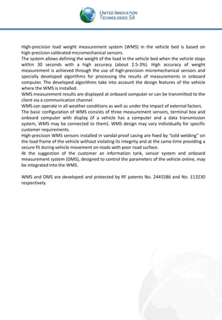


The document describes a high-precision load weight measurement system (WMS) for commercial vehicles. The WMS uses micromechanical sensors to measure the weight of cargo in the vehicle bed with 2.5-3% accuracy. It can provide measurements in all weather conditions. The WMS benefits various stakeholders: it helps manufacturers by monitoring vehicle usage conditions, helps logistics companies track cargo in real-time, and helps authorities efficiently measure weights. The system integrates with an onboard measurement system to further monitor vehicle parameters.


