Download to read offline
![UML-Based Integration Testing
Jean Hartmann Claudio Imoberdorf Michael Meisinger
Siemens Corporate Research Siemens Corporate Research Technical University, Munich
755 College Road East 755 College Road East Arcisstraße 21
Princeton NJ 08540 Princeton NJ 08540 80333 München
++1 609 734 3361 ++1 609 734 3688 ++49 (89) 289-01
jhartmann@scr.siemens.com claudio@scr.siemens.com meisinger@gmx.de
Abstract These factors include:
Increasing numbers of software developers are using the Unified • The definition of the Unified Modeling Language (UML)
Modeling Language (UML) and associated visual modeling tools [14,15], a standardized way of modeling the static structure
as a basis for the design and implementation of their distributed, and dynamic behavior of components and their interfaces;
component-based applications. At the same time, it is necessary to • The standardization of object-oriented middleware, for
test these components, especially during unit and integration example, Microsoft’s COM/DCOM and OMG’s CORBA;
testing.
At Siemens Corporate Research, we have addressed the issue of • The continued refinement of object-oriented programming
testing components by integrating test generation and test languages, such as Java and C++, and integrated
execution technology with commercial UML modeling tools such development environments that provide extensive support for
as Rational Rose; the goal being a design-based testing creating distributed components.
environment. As a result, developers are implementing large numbers of
In order to generate test cases automatically, developers first components ranging from relatively simple graphical user
define the dynamic behavior of their components via UML interface (GUI) components to sophisticated server-side
Statecharts, specify the interactions amongst them and finally application logic [4]. In this paper, we are focusing on the latter
annotate them with test requirements. Test cases are then derived type of component development.
from these annotated Statecharts using our test generation engine As developers are delivering these complex, server-side
and executed with the help of our test execution tool. The latter components, they must also ensure that each component is
tool was developed specifically for interfacing to components delivered with a concise and unambiguous definition of its
based on COM/DCOM and CORBA middleware. interfaces, and the legal order in which operations may be
In this paper, we present our approach to modeling components invoked on them. Component interfaces and their protocol
and their interactions, describe how test cases are derived from specifications are being described or modeled in a variety of ways.
these component models and then executed to verify their For example, in the case of the Enterprise Java Beans
conformant behavior. We outline the implementation strategy of Specification [10], this is achieved through contracts and UML
our TnT environment and use it to evaluate our approach by Sequence Diagrams (also known as Message Sequence Charts).
means of a simple example. While a Sequence Diagram is useful at describing a specific
interaction scenario, it may require a large number of such
Keywords diagrams to completely specify the interaction of a complex
Distributed components, functional testing, test generation, test component with its client(s). A more concise and compact way,
execution, UML statecharts, COM/DCOM, CORBA. however, of representing these scenarios is to depict them using a
UML Statechart Diagram. It is this dynamic, behavioral
1. Introduction description that is used in this paper as a basis for modeling
While standardized testing strategies and tools have been components and their interfaces.
available for IC (hardware) components for many years, the Stimulating the interfaces to individual or groups of distributed
research and development of standardized testing techniques and components with inputs and monitoring as well as verifying the
tools for distributed software components has just begun [18]. resulting responses is considered to be a functional or black-box
Three key technological factors are not only allowing developers testing strategy [2]. In our approach, we use Statecharts as a basis
to design and implement components, but at the same time, they for generating such black-box tests, which developers can use for
are contributing towards the development of such testing unit and integration testing. If the components have not been
strategies. developed in-house or the source code is not available, as in the
case of third-party components, then it may be possible to derive
an abstracted Statechart for each or a subsystem of components.
In Section 2, we describe our approach for modeling components
and their interactions by means of Statecharts. Section 3 outlines
the way in which the individual Statecharts are combined into a
global behavioral model. In Section 4, we present the way in](https://image.slidesharecdn.com/hartmannim00-120418092820-phpapp02/85/Hartmann-im00-1-320.jpg)
![UML-Based Integration Testing
Jean Hartmann Claudio Imoberdorf Michael Meisinger
Siemens Corporate Research Siemens Corporate Research Technical University, Munich
755 College Road East 755 College Road East Arcisstraße 21
Princeton NJ 08540 Princeton NJ 08540 80333 München
++1 609 734 3361 ++1 609 734 3688 ++49 (89) 289-01
jhartmann@scr.siemens.com claudio@scr.siemens.com meisinger@gmx.de
Abstract These factors include:
Increasing numbers of software developers are using the Unified • The definition of the Unified Modeling Language (UML)
Modeling Language (UML) and associated visual modeling tools [14,15], a standardized way of modeling the static structure
as a basis for the design and implementation of their distributed, and dynamic behavior of components and their interfaces;
component-based applications. At the same time, it is necessary to • The standardization of object-oriented middleware, for
test these components, especially during unit and integration example, Microsoft’s COM/DCOM and OMG’s CORBA;
testing.
At Siemens Corporate Research, we have addressed the issue of • The continued refinement of object-oriented programming
testing components by integrating test generation and test languages, such as Java and C++, and integrated
execution technology with commercial UML modeling tools such development environments that provide extensive support for
as Rational Rose; the goal being a design-based testing creating distributed components.
environment. As a result, developers are implementing large numbers of
In order to generate test cases automatically, developers first components ranging from relatively simple graphical user
define the dynamic behavior of their components via UML interface (GUI) components to sophisticated server-side
Statecharts, specify the interactions amongst them and finally application logic [4]. In this paper, we are focusing on the latter
annotate them with test requirements. Test cases are then derived type of component development.
from these annotated Statecharts using our test generation engine As developers are delivering these complex, server-side
and executed with the help of our test execution tool. The latter components, they must also ensure that each component is
tool was developed specifically for interfacing to components delivered with a concise and unambiguous definition of its
based on COM/DCOM and CORBA middleware. interfaces, and the legal order in which operations may be
In this paper, we present our approach to modeling components invoked on them. Component interfaces and their protocol
and their interactions, describe how test cases are derived from specifications are being described or modeled in a variety of ways.
these component models and then executed to verify their For example, in the case of the Enterprise Java Beans
conformant behavior. We outline the implementation strategy of Specification [10], this is achieved through contracts and UML
our TnT environment and use it to evaluate our approach by Sequence Diagrams (also known as Message Sequence Charts).
means of a simple example. While a Sequence Diagram is useful at describing a specific
interaction scenario, it may require a large number of such
Keywords diagrams to completely specify the interaction of a complex
Distributed components, functional testing, test generation, test component with its client(s). A more concise and compact way,
execution, UML statecharts, COM/DCOM, CORBA. however, of representing these scenarios is to depict them using a
UML Statechart Diagram. It is this dynamic, behavioral
1. Introduction description that is used in this paper as a basis for modeling
While standardized testing strategies and tools have been components and their interfaces.
available for IC (hardware) components for many years, the Stimulating the interfaces to individual or groups of distributed
research and development of standardized testing techniques and components with inputs and monitoring as well as verifying the
tools for distributed software components has just begun [18]. resulting responses is considered to be a functional or black-box
Three key technological factors are not only allowing developers testing strategy [2]. In our approach, we use Statecharts as a basis
to design and implement components, but at the same time, they for generating such black-box tests, which developers can use for
are contributing towards the development of such testing unit and integration testing. If the components have not been
strategies. developed in-house or the source code is not available, as in the
case of third-party components, then it may be possible to derive
an abstracted Statechart for each or a subsystem of components.
In Section 2, we describe our approach for modeling components
and their interactions by means of Statecharts. Section 3 outlines
the way in which the individual Statecharts are combined into a
global behavioral model. In Section 4, we present the way in](https://image.slidesharecdn.com/hartmannim00-120418092820-phpapp02/75/Hartmann-im00-1-2048.jpg)
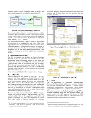
![which test cases are generated and executed using the global Figure 2 illustrates the Statechart for the Transmitter object
model. For Section 5 and 6, we provide an overview of the TnT shown in Figure 1. It comprises six states with a start and an end
environment that realizes the approach and apply it to an example. state. The transitions are labeled with call event descriptions
Related work, conclusions and future work are presented in corresponding to external stimuli being received from the tuser
Section 7 and 8. interface and internal stimuli being sent to the Timer component
via the timing interface and received from the ComCh component
2. Modeling Components in UML via the txport interface. These internal/external interfaces and
In this section, we describe the use of UML Statecharts in components are shown in Figure 1. Moreover, the nomenclature
modeling the dynamic behavior of components as well as the used for labeling the transitions is described in the next section
communication between them1. To better convey the concepts, we and relates to the way in which component interactions are
have illustrated the paper with an example. modeled.
Idle0
_tuser?msg
_txport?ack ^timing!cancel:_tuser!ack
PrepareSend0 MessageSent1
^_txport!data0:_timing!start ^_txport!data1:_timing!start
_timing?timeout _timing?tim eout
MessageSent0 PrepareSend1
_txport?ack ^_timing!cancel:_tuser!ack _tuser?msg
Figure 1: Alternating Bit Protocol Example Idle1
The example in Figure 1 represents an alternating bit
communication protocol2 in which there are four separate
components Timer, Transmitter, ComCh (Communication
Figure 2: Statechart Diagram for the Transmitter Object
Channel) and Receiver and several internal as well as external
interfaces and stimuli.
2.2 Communicating Statecharts
The protocol is a unidirectional, reliable communication protocol. In the following section, we describe how a developer would need
A user invokes a Transmitter component to send data messages to model the communication between multiple Statecharts, when
over a communication channel and to a Receiver component, using a commercial UML-based modeling tool. At present, UML
which then passes it on to another user. The communication does not provide an adequate mechanism for describing the
channel can lose data messages as well as acknowledgements. The communication between two components, so we adopted concepts
reliable data connection is implemented by observing possible from CSP (Communicating Sequential Processes) [6] to enhance
timeout conditions, repeatedly sending messages, if necessary, its existing notation.
and ensuring the correct order of the messages.
2.2.1 Communication Semantics
2.1 UML Statecharts In our approach, we wanted to select communication semantics
The Unified Modeling Language (UML) is a general-purpose that most closely relate to the way in which COM/DCOM and
visual modeling language that is used to specify, visualize, CORBA components interact in current systems. While such
construct and document the artifacts of a software system. components allow both synchronous and asynchronous
In this paper, we focus on the dynamic views of UML, in communications, we focus on a synchronous mechanism for the
particular, Statechart Diagrams. A Statechart can be used to purposes of this paper.
describe the dynamic behavior of a component or should we say In addition, there are two types of synchronous communication
object over time by modeling its lifecycle. The key elements mechanisms. The first, the shared (or global) event model, may
described in a Statechart are states, transitions, events, and broadcast a single event to multiple components, all of which are
actions. waiting to receive and act upon it in unison. The second model, a
States and transitions define all possible states and changes of point-to-point, blocking communication mechanism, can send a
state an object can achieve during its lifetime. State changes occur single event to just one other component and it is only these two
as reactions to events received from the object’s interfaces. components that are then synchronized. The originator of the
Actions correspond to internal or external method calls. event halts its execution (blocks) until the receiver obtains the
event. It is this point-to-point model that we adopted, because it
most closely resembles the communication semantics of
1
The nomenclature in this paper refers to UML, Revision 1.3. COM/DCOM and CORBA.
2
The name Alternating Bit Protocol stems from the message sequence
numbering technique used to recognize missing or redundant messages
and to keep up the correct order.](https://image.slidesharecdn.com/hartmannim00-120418092820-phpapp02/85/Hartmann-im00-2-320.jpg)
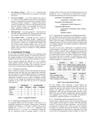
![Initial and final states are regular states. The initial state gives a TimerOn and GotAck have been inserted to separate the
starting point for a behavior description. Final states express multiple events _txport!data0:^_timing_start and
possible end points for the execution of a component. txport?ack^timing!cancel between the PrepareSend,
The transition annotations T contain a transition type as well as a MessageSent and Idle states shown in Figure 2.
connection name and an event name. Transition types can be
INTernal, SEND, RECEIVE and COMMunication. Transitions of
3.2.2 Composed State Machines
A composed state machine can be considered as the product of
type SEND and RECEIVE are external events sent to or received
multiple state machines. It is itself a state machine with the
from an external interface to the component’s state machine.
dynamic behavior of its constituents. As such, it would react and
SEND and RECEIVE transitions define the external behavior of a
generate output as a result of being stimulated by events specified
component and are relevant for the external behavior that can be
for the respective state machines. Based on the above definition of
observed. An INTernal transition is equivalent to a ε-transition
a finite state machine, the structure of a composed state machine
(empty transition) of a finite state machine [7]. It is not triggered
can be defined as follows:
by any external event and has no observable behavior. It
represents arbitrary internal action. COMMunication transitions Definition: Let A = (S1, M1, T1, δ1, s01, sf1) and B = (S2, M2, T2,
are special types of internal transitions representing interaction δ2, s02, sf2) be two state machines and S1 ∩ S2 = ∅. The composed
between two state machines. Such behavior is not externally state machine C = A#B has the following formal definition:
observable. When composing state machines, matching pairs of A#B = (S', M', T', δ', s0', F')
SEND and RECEIVE transitions with equal connection and event
names are merged to form COMMunication transitions. For S' = S1 x S2
example, the transitions highlighted by dark arrows in Figure 3 M' ⊂ (M1 × S2) ∪ (S1 × M2)
would be such candidates.
T' ⊂ T12 ∪ TCOMM
The definition of a state machine allows transitions that contain
single actions. Every action expressed by a transition annotation is T12 = (T1 ∪ T2) {SEND, RECEIVE with connections
interpreted as an atomic action. Component interaction can occur between A and B}
after each action. If several actions are grouped together without TCOMM = {COMM for matching events from T1 and T2}
the possibility of interruption, the states between the transitions
δ': S' × T' → S'
can be marked as intermediate states. Intermediate states (M ∈ S)
are introduced to logically group substructures of states and δ' is generated from δ1 and δ2 with the state machine
transitions. The semantics of intermediate states provide a composition schema
behavioral description mechanism similar to microsteps. Atomic s0' = (s01, s02) ∈ S'.
actions are separated into multiple consecutive steps, the
microsteps, which are always executed in one run. These F' = {(s1, s2) ∈ S' s1 ∈ F1 ∧ s2 ∈ F2}
microsteps are the outgoing transitions of intermediate states. This For example, a global state for A#B is defined as a two-tuple (s1,
technique is used in our approach as part of the process of s2), where s1 is a state of A and s2 is a state of B. These two states
converting the UML Statecharts into an internal representation. are referred to as part states. Initial state and final states of A#B
The result is a set of normalized state machines. are element and subset of this product. The possible transition
annotations are composed from the union of T1 and T2 and new
COMMunication transitions that result from the matching
Idle
transitions. Excluded are the transitions that describe possible
matches. Either COMMunication transitions are created from
_tuser?msg them or they are omitted, because no communication is possible.
PrepareSend
^_timing!cancel 3.2.3 Composition Method
A basic approach for composing two state machines is to generate
the product state machine by applying generative multiplication
^_tim ing!start rules for states and transitions. This leads to a large overhead,
GotAck
because many unreachable states are produced that have to be
TimerOn removed in later steps. The resulting product uses more resources
_timing?timeout than necessary as well as more computation time for generation
and minimization.
_txport! data0 _txport?ack Instead, our approach incorporates an incremental composition
and reduction algorithm that uses reachability computations. A
M essa ge Se nt global behavioral model is created stepwise. Beginning with the
global initial state, all reachable states and all transitions in
between are computed. Every state of the composed state machine
is evaluated only once. Due to the reachability algorithm, the
Figure 4: Normalized Transmitter Component intermediate data structures are at no time larger than the result of
one composition step. States and transitions within the composed
Figure 4 shows such a state machine for a simplified version of
state machines that are redundant in terms of external observation
the Transmitter object. Two additional, intermediate states
are removed. By applying the reduction algorithm using heuristic](https://image.slidesharecdn.com/hartmannim00-120418092820-phpapp02/85/Hartmann-im00-4-320.jpg)
![rules, it is possible to detect redundancies and to reduce the size model and later processed. The schema we used was based on a
of a composed state machine before the next composition step. composition schema developed by Sabnani et al. [16]. We
Defined subsystems are processed independently sequentially. For enhanced it to include extensions for connections, communication
each subsystem, the composition algorithm is applied. The inputs transitions, and intermediate states.
for the composition algorithm are data structures representing the We are assuming throughout this composition process that the
normalized communicating state machines of the specified individual as well as composed state machines have deterministic
components within the current subsystem. The connection behavior. We also ensure that the execution order of all
structure between these components is part of these data component actions is sequential. This is important as we then
structures. The order of the composition steps determines the size wish to use the global model to create test cases that are
and complexity of the result for the next step and therefore the dependent on a certain flow of events and actions; we want to
effectiveness of the whole algorithm. The worst case for generate linear and sequential test cases for a given subsystem.
intermediate composition products is a composition of two
components with no interaction. The maximum possible number 3.2.4 Complexity Analysis
of states and transitions created in this case resembles the product As we are composing the product of two state machines, the worst
of two state machines. case complexity would be O(n2) assuming n is the number of
states in a state machine. However, our approach often does much
It is therefore important to select the most suitable component for better than this due to the application of the heuristic reduction
the next composition step. The minimal requirement for the rules that can help to minimize the overall size of the global
selected component is to have a common interface with the other model during composition and maintain its observational
component. This means that at least one connection exists to the equivalence [11].
existing previously calculated composed state machine.
Typically, the reduction algorithm being used has linear
A better strategy with respect to minimizing the size of complexity with respect to the number of states [16]. For example,
intermediate results is to select the state machine with the highest it was reported that the algorithm was applied to a complex
relative number of communication relationships or interaction communication protocol (ISDN Q.931), where it was shown that
points. A suitable selection norm is the ratio of possible instead of generating over 60,000 intermediate states during
communication transitions to all transitions in a state machine. composition, the reduction algorithm kept the size of the model to
The component with the highest ratio exposes the most extensive approximately 1,000 intermediate states. Similar results were
interface to the existing state machine and should be selected. reported during use of the algorithm with other systems. The
algorithm typically resulted in a reduction in the number of
intermediate states by one to two orders of magnitude.
3.2.5 Example
Taking the normalized state machine of the Transmitter
component in Figure 4 and the Timer component in Figure 3, the
composition algorithm needs to perform only one iteration to
generate the global behavioral model in Figure 5.
A global initial state Idle_Stopped is created using the initial
states of the two state machines. This state is added to the list of
unmarked states. The composition schema is now applied for
every state within this list to generate new global states and
transitions until the list is empty. The reachability algorithm
creates a global state machine comprising six states and seven
transitions. Three COMMunication transitions are generated,
which are identified by a hash mark in the transition label
Table 1 : Decision Table for Computing Successor States and showing the communication connection and event.
Transitions The example shows the application of the decision table. In the
first global state, Idle_Stopped, part state Idle has an
This incremental composition and reduction method also specifies
outgoing receive transition to PrepareSend using an external
a composition schema. For every combination of outgoing
connection. Part state Stopped has also an outgoing receive
transitions of the part states, a decision table (shown in Table 1) is
used to compute the new transitions for the composed state transition to Running with a connection to the other component.
machine. According to the Decision Rule #4 of the table, the transition with
the external connection is inserted into the composed state
If a new transition leads to a global state that is not part of the machine and the other transition is ignored. The new global
existing structure of the composed state machine, it is added to an receive transition leads to the global state
unmarked list. The transition is added to the global model. PrepareSend_Stop.
Exceptions exist, when part states are marked as intermediate.
Every reachable global state is processed and every possible new For the next step, both part states include transitions, which use
global transition is inserted into the composed state machine. The internal connections. They communicate via the same connection
algorithm terminates when no unmarked states remain. This timing and the same event - these are matching transitions.
means that every reachable global state was inserted into the According to Decision Rule #1 of the table, a communication](https://image.slidesharecdn.com/hartmannim00-120418092820-phpapp02/85/Hartmann-im00-5-320.jpg)
![transition is included in the composed state machine that leads to 4.2 Test Generation
the global state TimerOn_Running. These rules are applied Before proceeding with a description of the test generation and
repeatedly until all global states are covered. execution steps, we would like to emphasize the following:
• Our approach generates a set of conformance tests. These test
Idle_Stop cases ensure the compliance of the design specification with
the resulting implementation.
_tuser?msg • It is assumed that the implementation behaves in a
deterministic and externally controllable way. Otherwise, the
P repareSend_Stop generated test cases may produce incorrect results.
^_timing#cancel _timing#start
4.2.1 Category-Partition Method
For test generation, we use the Test Development Environment
TimerOn_Running ^_timing#timeout (TDE), a product developed at Siemens Corporate Research [1].
TDE processes a test design written in the Test Specification
Language (TSL). This language is based on the category-partition
^_txport!data0
method, which identifies behavioral equivalence classes within
MessageSent_Running the structure of a system under test.
A category or partition is defined by specifying all possible data
_txport?ack _timer?extTimeout choices that it can represent. Such choices can be either data
values or references to other categories or partitions, or a
GotAck_Running MessageSent_Timeout
combination of both. The data values may be string literals
representing fragments of test scripts, code, or case definitions,
which later can form the contents of a test case.
Figure 5: Global Behavioral Model for the TransmitterTimer A TSL test design is now created from the global behavioral
Subsystem model by mapping its states and transitions to TSL categories or
partitions, and choices. States are the equivalence classes and are
4. Test Generation and Execution therefore represented by partitions. Each transition from the state
In the preceding sections, we discussed our approach to modeling is represented as a choice of the category/partition. Only partitions
individual or collections of components using UML Statecharts, are used for equivalence class definitions, because paths through
and establishing a global behavioral model of the composed the state machine are not limited to certain outgoing transitions
Statecharts. In this section, we show how this model can be used for a state; this would be the case when using a category. Each
as the basis for automatic test generation and execution during transition defines a choice for the current state, combining a test
unit and integration testing. data string (the send and receive event annotations) and a
reference to the next state. A final state defines a choice with an
4.1 Unit and Integration Testing empty test data string.
After designing and coding each software component, developers
4.2.2 Generation Procedure
perform unit testing to ensure that each component correctly
A recursive, directed graph is built by TDE that has a root
implements its design and is ready to be integrated into a system
category/partition and contains all the different paths of choices to
of components. This type of testing is performed in isolation from
plain data choices. This graph may contain cycles depending on
other components and relies heavily on the design and
the choice definitions and is equivalent to the graph of the global
implementation of test drivers and test stubs. New test drivers and
state machine. A test frame, that is, test case is one instance of the
stubs have to be developed to validate each of the components in
initial data category or partition, that is, one possible path from
the system.
the root to a leaf of the (potentially infinite) reachability tree for
After unit testing is concluded, the individual components are the graph.
collated, integrated into the system, and validated again using yet
An instantiation of a category or partition is a random selection of
another set of test drivers. At each level of testing, a new set of
a choice from the possible set of choices defined for that
custom test drivers is required to stimulate the components. While
category/partition. In the case of a category, the same choice is
each component may have behaved correctly during unit testing, it
selected for every instantiation of a test frame. This restricts the
may not do so when interacting with other components.
branching possibilities of the graph. With a partition, however, a
Therefore, the objective of integration testing is to ensure that all
new choice is selected at random with every new instantiation.
components interact and interface correctly with each other, that
This allows full branching within the graph and significantly
is, have no interface mismatches. This is commonly referred to as
influences test data generation. The contents of a test case consist
bottom-up integration testing.
of all data values associated with the edges along a path in the
Our approach aims at minimizing the testing costs, time and effort graph.
associated with initially developing customized test drivers, test
stubs, and test cases as well as repeatedly adapting and rerunning 4.2.3 Coverage Requirements
them for regression testing purposes at each level of integration. The TSL language provides two types of coverage requirements:](https://image.slidesharecdn.com/hartmannim00-120418092820-phpapp02/85/Hartmann-im00-6-320.jpg)
![tests. In this case, the incremental integration test strategy resulted composing. Dependent on the implementation, the size of the
in more test cases being generated than the big-bang approach, event queue can be limited or not. If not, mechanisms have to be
but smaller integration steps usually result in a more stable system implemented to detect the overflow of queues. When generating
and a higher percentage of detected errors. An examination of the test cases for asynchronously communicating systems, the
generated test cases shows that they are not free of redundancy or complexity may quickly lead to scalability problems that would
multiple coverage of communication transitions, but they come need to be examined and addressed in future work. Methods for
relatively close to the optimum. asynchronously communicating systems are presented in [5,9, 20].
Component interaction is modeled by our approach using an event
7. Related Work (message) exchange containing no parameters and values. Future
Over the years, there have been numerous papers dedicated to the
work will result in the modeling of ‘parameterized’
subject of test data generation [1,3,8,13,17,19,21]. Moreover, a
communication. To achieve this, the model specification must be
number of tools have been developed for use within academia and
enhanced with annotations about possible data values and types as
the commercial market. These approaches and tools have been
well as test requirements for these values. TDE allows test case
based on different functional testing concepts and different input
generation using data variations with samples out of a possible
languages, both graphical and textual in nature.
range of parameter values. Pre- and post-conditions can constrain
However, few received any widespread acceptance from the valid data values. These constraints can be checked during test
software development community at large. There are a number of execution, which extends the error detecting possibilities.
reasons for this. First, many of these methods and tools required a
UML allows users to model Statecharts with hierarchical state
steep learning curve and a mathematical background. Second, the
machines and concurrent states. While the global behavioral
modeling of larger systems beyond single components could not
model presented in this paper can model components with nested
be supported, both theoretically and practically. Third, the design
states and hierarchical state machines, the internal data conditions
notation, which would be used as a basis for the test design, was
of these state machines (meaning the global state machine
often used only in a particular application domain, for example,
variables) influencing the transition behavior are not supported.
SDL is used predominantly in the telecommunications and
Concurrent states are also not supported as yet.
embedded systems domain.
In future work, we hope to support the developer with an optimal
However, with the widespread acceptance and use of UML
integration test strategy. By examining the type and extent of the
throughout the software development community as well as the
interactions between components, our environment could provide
availability of suitable tools, this situation may be about to
suggestions to the developer as to the order in which components
change. Apart from our approach, we know of only one other
need to be integrated. This could include analyses of the
effort in this area. Offutt et al. [12] present an approach similar to
intermediate composition steps as well as an initial graphical
ours in that they generate test cases from UML Statecharts.
depiction of the systems and its interfaces. Such an approach
However, their approach has a different focus in that they examine
could significantly influence the effectiveness, efficiency and
different coverage requirements and are only able to generate tests
quality of the test design.
for a single component. Furthermore, they do not automate the
test execution step in order for developers to automatically When modeling real-time systems, timing aspects and constraints
generate and execute their tests. In addition, they do not become essential. In future work, we hope to analyze real-time
specifically address the problems and issues associated with modeling and testing requirements. For instance, test cases could
modeling distributed, component-based systems. be annotated with real-time constraints. Assertions or post-
conditions within the model could also contain such information
8. Conclusion and Future Work which could be checked during test execution.
In this paper, we described an approach that aims at minimizing
the testing costs, time and effort associated with developing 9. Acknowledgements
customized test drivers and test cases for validating distributed, We would like to thank Tom Murphy, the Head of the Software
component-based systems. Engineering Department at Siemens Corporate Research as well
as Professor Manfred Broy and Heiko Lötzbeyer at the Technical
To this end, we describe and realize our test generation and test
University, Munich.
execution technology and integrate it with a UML-based visual
modeling tool. We show how this approach supports both the unit 10. References
and integration testing phases of the component development
[1] Balcer M., Hasling W., Ostrand T., Automatic
lifecycle and can be applied to both COM- and CORBA-based
systems. We briefly outline our implementation strategy and Generation of Test Scripts from Formal Test
evaluate the approach using the given example. In the following Specifications, Proceedings of ACM SIGSOFT’89 -
paragraphs, we focus on some of the issues resulting from this Third Symposium on Software Testing, Verification,
work. and Analysis (TAVS-3), ACM Press, pp. 257-71, June
Software systems, especially embedded ones, use asynchronous 1990.
communication mechanisms with message queuing or shared [2] Beizer, Boris, Software Testing Techniques, Second
(global) messages instead of the synchronous communication Edition. Van Nostrand Reinhold, 1990.
mechanism adopted by our approach. Asynchronous
communication is more complex to model, because it requires the [3] Derrick J., Boiten E.A.: Testing Refinements by
modeling of these queued messages and events. Furthermore, Refining Tests, ZUM’98 - The Z Formal Specification
communication buffers must be included, when modeling and Notation, Springer-Verlag, pp. 265-83, Sept. 1998.](https://image.slidesharecdn.com/hartmannim00-120418092820-phpapp02/85/Hartmann-im00-10-320.jpg)
![[4] Grasso Max, Distributed Component Systems: The [14] Rumbaugh J., Blaha M., Premerlani W., Eddy F.,
New Computing Model, Application Development Lorensen W.: Object-Oriented Modeling and Design.
Trends, pp. 43-51, Nov. 1999. Prentice Hall, 1991.
[5] Henniger O., One test case generation from [15] Rumbaugh J., Jacobson I., Booch G.: The Unified
asynchronously communicating state machines, in: Modeling Language Reference Manual, Addision-
Testing of Communicating Systems Vol. 10, Chapman Wesley, 1999.
& Hall, Sept. 1997. [16] Sabnani K. K., Lapone Aleta M., Uyar M. Ümit: An
[6] Hoare C. A. R, Communicating Sequential Processes. Algorithmic Procedure for Checking Safety Properties
Prentice Hall, 1987. of Protocols. IEEE Transactions on Communications,
[7] Hopcroft J., Ullman J., Introduction to Automata Vol. 37, No. 9, Sept. 1989.
Theory, Languages and Computation, 3rd Edition, [17] Sarikaya B., Protocol Test Generation, Trace Analysis,
Addison-Wesley, 1994. and Verification Techniques, Proceedings of Second
[8] Ince D.C., The Automatic Generation of Test Data, Workshop on Software Testing, Verification, and
The Computer Journal, vol. 30, no. 1, pp. 62-9, Analysis (TAVS-2), IEEE Computer Society Press, pp.
February 1987. 123-30, July 1988.
[9] Kim M., Shin J., Chanson S.T., Kang S.: An Approach [18] Szyperski Clemens: Component Software. Beyond
for Testing Asynchronous Communicating Systems, Object-Oriented Programming. Addison-Wesley
IEICE Transactions or Communications, Vol. E82-B, Longman Ltd., 1998.
No. 1, Jan. 1999. [19] Tai K.C., Predicate-Based Test Generation for
[10] Matena V., Hapner M., Enterprise Java Beans Computer Programs, Proceedings of 15th International
Specification, Version 1.1, Sun Microsystems, Dec. Conference on Software Engineering (ICSE), IEEE
1999. Computer Society Press, pp. 267-76, May 1993.
[11] Milner R., Communication and Concurrency, Prentice- [20] Waeselynck H. and Thevenod-Fosse P., A Case Study
Hall, 1st Edition, 1995. in Statistical Testing of Reuseable Concurrent Objects,
Proceedings of 3rd European Dependable Computing
[12] Offutt J., Abdurazik A., Generating Test Cases from Conference (EDCC-3), LNCS 1667, pp. 401-418,
UML Specifications. Proceedings of 2nd International 1999.
Confererence on UML’99, Oct. 1999.
[21] White L.J., and Sahay P.N., A Computer System for
[13] Poston R., T: The Automatic Test Case Data Generating Test Data using the Domain Strategy,
Generator, Proceedings of 4th Annual Pacific Proceedings of SOFTFAIRII - 2nd Conference on
Northwest Software Quality Assurance Conference, pp. Software Development Tools, Techniques and
168-76, Sept. 1986. Alternatives, IEEE Computer Society Press, pp. 38-45,
Dec. 1985.](https://image.slidesharecdn.com/hartmannim00-120418092820-phpapp02/85/Hartmann-im00-11-320.jpg)

This document discusses an approach to integration testing of distributed components modeled using UML statecharts. The approach involves: 1. Modeling the dynamic behavior of individual components using UML statecharts, including specifying interactions between components. 2. Combining the individual statechart models into a global behavioral model that preserves the behavior of each component. 3. Generating test cases automatically from the global model by deriving tests from annotated statechart transitions and interactions between components. 4. Executing the generated test cases using a test execution tool to verify the conformant behavior of components. The approach aims to provide a design-based testing environment for testing distributed components during unit and integration testing.