This chapter discusses the beneficiation of phosphate ores through froth flotation. There are two main types of phosphate ore deposits - igneous deposits which account for about 15% of production, and sedimentary deposits which account for about 70% of production. Beneficiation depends on the specific mineralogy of the ore. For carbonatite and dolomitic ores without silicates, direct flotation of carbonates is used to produce a phosphate concentrate. For ores containing silicates along with carbonates, bulk flotation is first used to produce a carbonate-phosphate concentrate which is then separated. Various depressants have been developed and tested for selectively depressing phosphate minerals to enable flotation of carbon


![26.3 Flotation beneficiation of different phosphate ore types 3
been found that flotation behavior of these two minerals using either anionic or cat-
ionic collector is virtually the same.
A number of researchers [1,2] have developed methods for beneficiation of cal-
careous phosphate ores using the fatty acid method.
Studies also performed using sodium oleate as the selective collector for apatite
[3]. Using sodium oleate–sodium silicate system, the selectivity is affected by flota-
tion pH and the level of sodium silicate.
Figure 26.1 shows the effect on pH on apatite and calcite using sodium oleate–
silicate system.
The highest apatite recovery was achieved between pH 8.0 and pH 9.0. Experi-
mental testwork was also performed at pH 8.0 with different levels of sodium silicate.
These results are presented in Figure 26.2. It appears from the results that higher lev-
els of sodium silicate have no significant effect on apatite and calcite grade recovery.
Most recently, a number of processes are developed for sedimentary carbonate–
apatite flotation using inverse flotation of carbonates with fatty acid collector and
depression of apatite using various depressant.
Some of the processes developed by various research organizations are discussed
below.
Sulfuric acid depression system [4]. In this process, the apatite minerals are
depressed by using sulfuric acid in slightly acid pulp (pH=5.0–5.5), while floating
carbonate using fatty acid. It is interesting to note that due to rapid pH increase in the
presence of calcite, the conditioning time with H2SO4 and collector was only 1min.
The results of this study showed that this process is relatively selective and good
concentrate grade can be produced.
Aluminum sulfate/Na, K-tartrate process [5]. The process uses Na, K-tartrate and
aluminum or iron sulfate to depress apatite and oleic acid with pine oil to float car-
bonate gangue at pH 7.5–8.2. It was postulated that conditioning of the pulp with
FIGURE 26.1
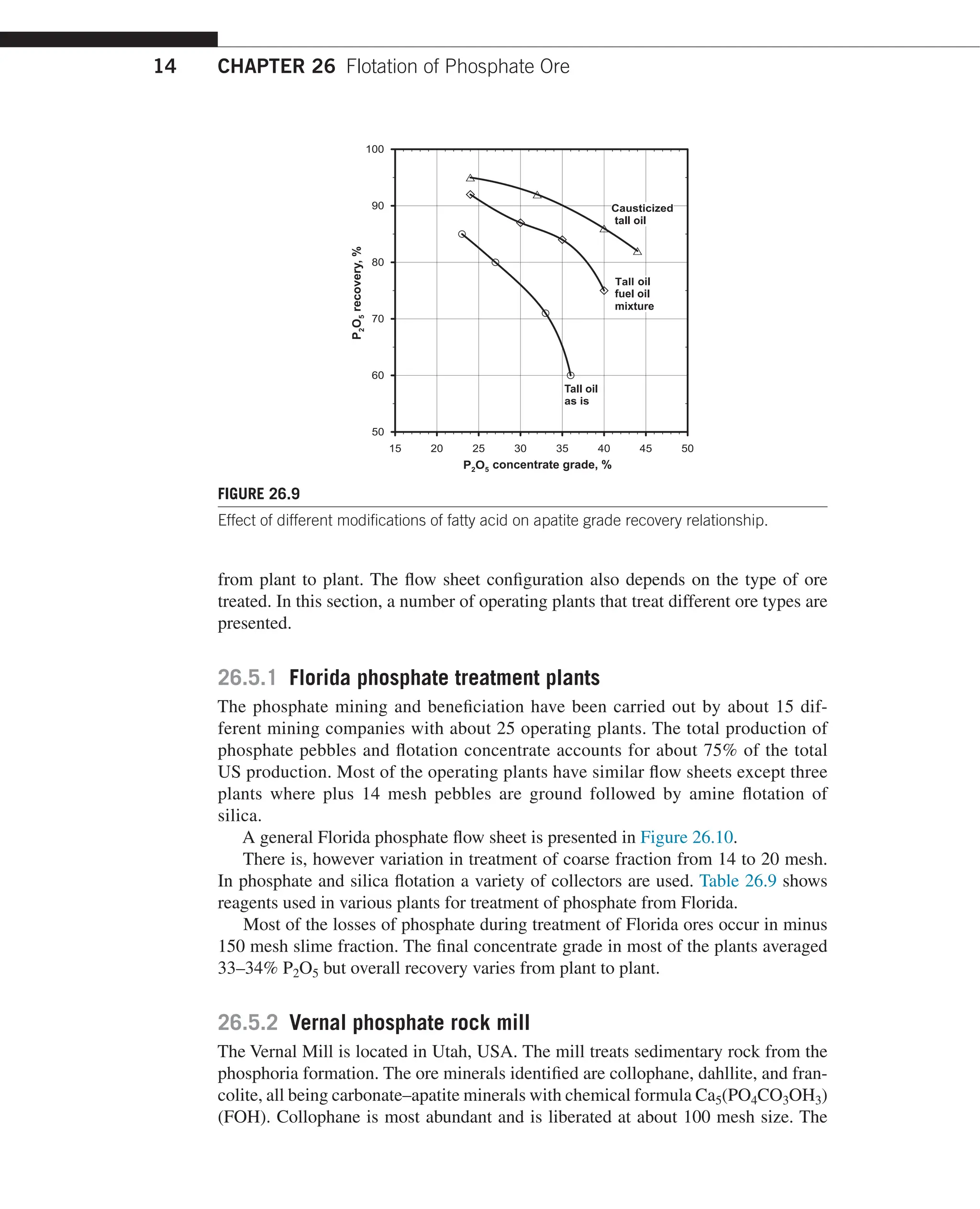
Flotation results as a function of pH (sodium oleate=200g/t, sodium silicate=250g/t).](https://image.slidesharecdn.com/handbook-of-flotation-reagents-chemistry-theory-and-practice-flotation-of-industrial-minerals-240217205157-8cbf963f/75/Handbook-of-flotation-reagents-_-chemistry-theory-and-practice-_-flotation-of-industrial-minerals-6-2048.jpg)
![CHAPTER 26 Flotation of Phosphate Ore
4
Al2(SO4)3 plus K-tartrate mixture (Ratio 1:2) causes the formation of a strongly elec-
tronegative film on the phosphate surface that may hinder the adsorption of anionic
collector which causes apatite depression. Using this method an apatite concentrate
assaying 27.1–30.7% P2O5, 42.9–55% CaO, and 1.5–6.3 MgO was obtained at
66–84.7% P2O5 recovery was obtained. The MgO content of concentrate was higher
than acceptable.
US bureau of mine process [6]. Using this process the phosphate minerals are
depressed by hydrofluorosilicic acid (H2SiF6), while carbonate minerals are floated
using fatty acid emulsions. This process has been used to float dolomite in a pilot
plant scale from an Idaho phosphate ore. Distilled tall oil was used as a collector
(1–2kg/t) at pH 6.0. This process gave relatively poor selectivity. The best phosphate
concentrate grade assaying 25–33% P2O5 and 1.4–6.5% MgO.
Tennessee valley diphosphonic acid process [7]. In this process, phosphate min-
erals are depressed using ethylidene hydroxydiphosphonic acid while carbonate is
floated using a fatty acid collector at pH 6.0–6.5. Using this method, phosphate con-
centrate assaying 29–32% P2O5 and 1.4–4.7 MgO was obtained at P2O5 recovery of
71–83% P2O5. The MgO/P2O5 weight ratio was too high.
Industrial minerals and chemical corporation cationic process [8]. This process
is best applied on the ores with low silica content or feed from which silica is first
removed by using bulk phosphate calcite flotation and depression. Carbonate min-
erals (calcite and dolomite) are depressed by hydrofluoric acid in slightly acid pH
(5.0–6.0) while floating phosphate with amine (Armac T, tallow amine acetate) and
fuel oil.
Flotation test results have indicated that MgO content of the concentrate was too
high (1.8–4.2% MgO). The P2O5 recovery using this process was relatively low.
FIGURE 26.2
Effect of level of sodium silicate on calcite apatite separation at pH 8.0.](https://image.slidesharecdn.com/handbook-of-flotation-reagents-chemistry-theory-and-practice-flotation-of-industrial-minerals-240217205157-8cbf963f/75/Handbook-of-flotation-reagents-_-chemistry-theory-and-practice-_-flotation-of-industrial-minerals-7-2048.jpg)
![26.3 Flotation beneficiation of different phosphate ore types 5
Phosphoric acid process [9]. In this process, phosphoric acid is used to depress
phosphate minerals in slightly acid pH (5.0–5.5) while floating carbonate with fatty
acid. It is postulated that phosphate ions are specifically adsorbed on the phosphate
surface causing formation of electronegative film thus causing phosphate depression.
In this study oleic acid was used. Flotation test results showed that the concentrate
averaged 1.0 MgO giving the ratio of MgO/P2O5 of 0.03, which is acceptable. Using
this method, good P2O5 grade and recovery was achieved.
Using the above process, two flow sheets were used; these include:
1.
Direct carbonate flotation. This flow sheet (Figure 26.3) is used when the ore
contained small quantities or no silicate.
2.
Bulk, carbonate phosphate flotation followed by carbonate/phosphate separa-
tion. This flow sheet (Figure 26.4) is used on the ore that contained silicate
together with carbonate.
Ore
–48 mesh
+400 mesh
+400 mesh
– 400 mesh
to waste
Carbonate P2O5 concentrate
concentrate 32.5% P2O5
to waste 75% P2O5 recovery
+48 mesh
P2O5 depressant
Carbonate
flotation
Crushing
Screening
(48 mesh)
Screening
(400 mesh)
Conditioning
Conditioning
Rod milling
Carbonate collector
FIGURE 26.3
Flow sheet used in beneficiation of carbonatite ore without silicate present in the ore.](https://image.slidesharecdn.com/handbook-of-flotation-reagents-chemistry-theory-and-practice-flotation-of-industrial-minerals-240217205157-8cbf963f/75/Handbook-of-flotation-reagents-_-chemistry-theory-and-practice-_-flotation-of-industrial-minerals-8-2048.jpg)


![CHAPTER 26 Flotation of Phosphate Ore
8
26.3.2 Direct flotation of phosphate from the ores containing
carbonate and dolomite
In recent studies, research work was carried out on direct apatite flotation from car-
bonaceous gangue minerals using various depressant and or new collectors.
A new process for the separation of a phosphate mineral from carbonaceous
gangue using direct apatite flotation has been developed [10]. The process is based
on carbonaceous gangue depression using phenol–formaldehyde copolymers such
as Resol, novolak, and melamine-modified novolak. Novolak can be prepared from
phenol and formaldehyde, in the presence of acid catalyst. Resol on the other hand
may be prepared from phenol and formaldehyde in the presence of alkali catalyst.
These depressants are tested on the ore assaying 6.9% P2O5, 30.8% carbonates
and the remaining being silicates.
The results obtained with different dosages of collector and depressants are
shown in Table 26.3. Collectors used in these experiments were tall oil fatty acid
modified with triethoxy butane.
Another depressant system consisting of Depressant System A3-2 plus oxalic
acid was examined on the ore from Lalitpur, Uttar Pradesh, India [11]. The ore
assayed 15% P2O5, 52% SiO2, 3% Al2O3, 28% CaO. Collector used in the experi-
mental testwork (Emulsion A) was a mixture of tall oil (45%) plus sarcosine OS100
(45%) modified with coal oil (10%). Lilaflot OS100 is manufactured by AKZO
Nobel.
Depressant A3-2 is a mixture of sodium silicate aluminum sulfate and sodium
bisulfate in a ratio of Na2SiO3:Al(SO4)3:Na2S2O3 =(38:38:24).
The use of oxalic acid improved silica rejection. The effect of oxalic acid addi-
tions on silica assays of the apatite concentrate is illustrated in Figure 26.5.
Collector emulsion A1 is a highly selective collector for the ores containing sil-
ica, calcite, and dolomite. The effectiveness of this collector is compared with other
collectors in Figure 26.6.
Continuous test results obtained on the ore are shown in Table 26.4.
The other known method is calcination of the ore at about 700°C followed by
quenching, washing, and apatite flotation. No industrial application of this method
exists.
Table 26.3 Effect of Phenol–Formaldehyde Copolymers on Phosphate Flotation
Collector, g/t Frother, g/t Depressant, g/t
Apatite Concentrate
% P2O5 Recovery %
50 10 Resol=125 35.9 80.6
100 10 Resol=250 28.7 78.3
100 10 Resol=350 35.8 81.3
250 10 Resol=200 35.1 84.9
250 10 No depressant 18.4 63.7
250 10 Novolak=50 30.2 93.9](https://image.slidesharecdn.com/handbook-of-flotation-reagents-chemistry-theory-and-practice-flotation-of-industrial-minerals-240217205157-8cbf963f/75/Handbook-of-flotation-reagents-_-chemistry-theory-and-practice-_-flotation-of-industrial-minerals-11-2048.jpg)

![CHAPTER 26 Flotation of Phosphate Ore
10
Table 26.4 Results of Continuous Locked Cycle Test Using New Depressant and
Collector System
Reagents
Added, g/t Product Wt %
Assays %
%
Distribution
P2O5 MgO SiO2 Fe2O3 P2O5
Depress
A3.2=900
Oxalic
acid=200
Coll
EmAa =500
P2O5 Cl.
concentrate
42.40 36.22 0.08 5.50 0.80 97.5
P2O5
combined
tails
57.60 0.68 – – – 2.5
Feed 100.00 15.75 – – – 100.0
aCollector EmA- modified fatty acid with Fuel oil and Pine oil.
Various processes have been developed for the removal of iron from apatite
concentrate including scrubbing for surface cleaning, gravity separation, magnetic
separation, and flotation using specific iron containing gangue depressants. Often, a
combination of two or more of these processes is used to reduce iron content of the
apatite concentrate to acceptable levels.
Attrition scrubbing is used to remove iron coating from the apatite mineral sur-
faces, which is often the case with crystalline apatite contained in igneous ore.
Heavy liquid separation of iron bearing minerals is also practiced. Good separa-
tion can be achieved with coarsely liberated particles.
One of the methods studied involves the use of silicates with a different modulus
[12]. The results indicate (Table 26.5) that the silicate with a modulus of 2, improved
iron rejection during phosphate flotation.
Experiments conducted with different mixture of silicate and metal salt showed
improvements in apatite grade and iron rejection. Table 26.6 shows the effect of dif-
ferent ratios of silicate and metal salt on apatite grade and recovery. In these experi-
ments AlCl3 and CaCl2 were used.
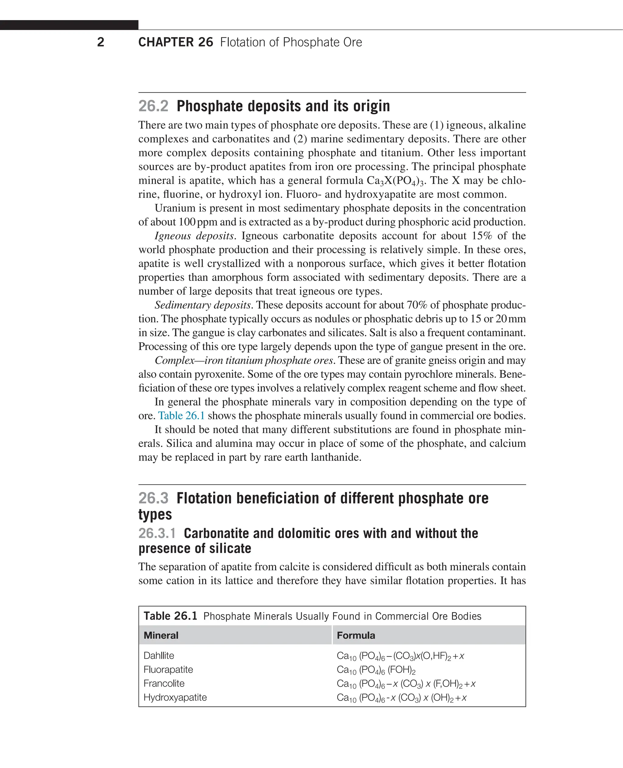
In beneficiation of high iron ores a typical reagent scheme includes sodium sili-
cate, caustic tapioca, or corn starch as iron and silicate depressants and tall oil fatty
acid/fuel oil mixture for apatite flotation (Figure 26.7).
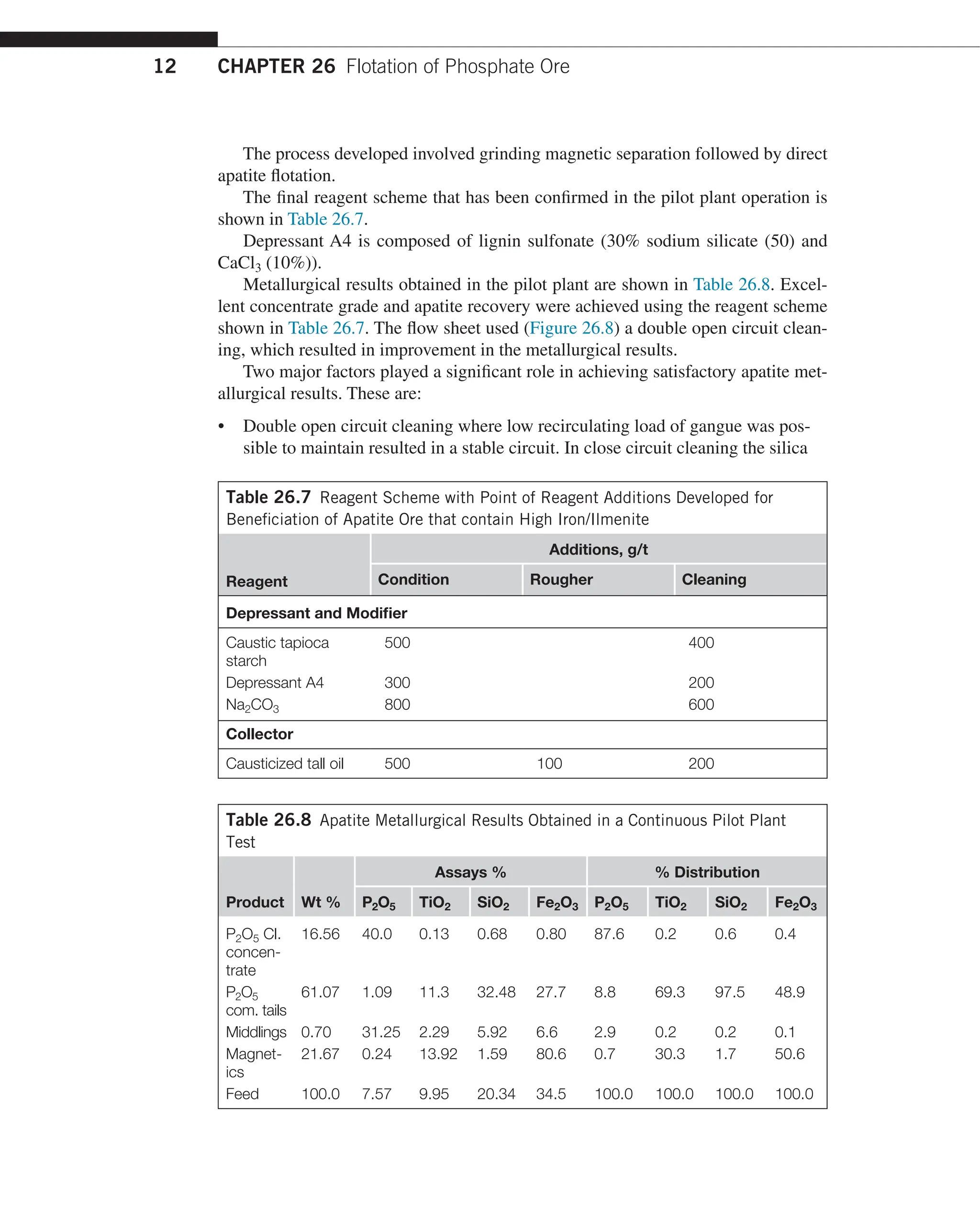
Most recently extensive laboratory and pilot plant studies were conducted on
complex igneous ore containing iron, ilmenite and apatite [13] from Canada.
Table 26.5 Effect of Modulus of Sodium Silicate on Flotation Performance of
High Iron Apatite Ore
Modulus
of Sodium
Silicate
Grade at 90% P2O5 Recovery Ratio P2O5
% P2O5 % Fe2O3 % Al2O3 Fe2O3 + Al2O3
1.0 36.2 7.1 0.28 4.9
2.1 37.5 6.0 0.25 6.0
3.3 35.8 8.4 0.31 4.1](https://image.slidesharecdn.com/handbook-of-flotation-reagents-chemistry-theory-and-practice-flotation-of-industrial-minerals-240217205157-8cbf963f/75/Handbook-of-flotation-reagents-_-chemistry-theory-and-practice-_-flotation-of-industrial-minerals-13-2048.jpg)
![26.4 Beneficiation of high iron and mixed iron, titanium ores 11
Table 26.6 Effect of Different Silicate–Metal Salt Mixtures on Apatite Flotation
from High Iron Ore
Metal
Salt
Metal/
Silica
Ratio
Assays % % Distribution
P2O5 Fe2O3 Al2O3 P2O5 Fe2O3 Al2O3
AlCl3 0.2 36.5 6.6 0.25 85.6 9.1 24.9
AlCl3 0.4 37.8 4.7 0.23 83.6 6.1 21.6
AlCl3 0.6 37.1 4.6 0.24 79.7 5.8 21.9
CaCl2 0.2 38.2 5.5 0.23 83.5 7.0 21.4
CaCl2 0.4 38.5 4.4 0.23 82.5 5.5 21.0
CaCl2 0.6 38.3 4.7 0.22 76.4 5.5 18.7
No salt – 36.2 7.9 0.30 86.5 11.1 27.4
2UH
3ULPDU
VOLPHV
2YHUVL]H
PHVK
6HFRQGDUVOLPHV
±PHVK
7DLOLQJV
,URQQRQIORDW
32FRQFHQWUDWH
32
)H2
32UHFRYHU
32 URXJKHU
:DVKLQJ
*ULQGLQJ
6FUXEELQJ
RQGLWLRQLQJ
32 FOHDQHU
±PHVK
FIGURE 26.7
Flow sheet used in flotation of apatite from the ore that contain high iron.](https://image.slidesharecdn.com/handbook-of-flotation-reagents-chemistry-theory-and-practice-flotation-of-industrial-minerals-240217205157-8cbf963f/75/Handbook-of-flotation-reagents-_-chemistry-theory-and-practice-_-flotation-of-industrial-minerals-14-2048.jpg)
![26.5 Plant practice in beneficiation of phosphate ores 15
2UH
3ULPDU
VOLPHV
PHVKPDUNHWDEOH
SHEEOHV
±PHVK
VOLPHV
±PHVK
V
J
Q
L
O
L
D
7
V
J
Q
L
O
L
D
7
6L2 )LQDO
FRQFHQWUDWH 32
WRWDLOLQJV FRQFHQWUDWH
PHVK
32 URXJKHU
IORWDWLRQ
:DVKLQJ
6L]LQJ
'HVOLPLQJ
$FLGWUHDWPHQW
'HVOLPLQJ
32 URXJKHU
IORWDWLRQ
6L2 IORWDWLRQ
FIGURE 26.10
General flow sheet for beneficiation of Florida phosphates.
Table 26.9 List of Collectors Used in Beneficiation of Florida Phosphate
Phosphate Circuit Silica Circuit
Collectors Extenders Modifiers Collectors
Soap skimming’s No. 5 fuel oil NaOH Liquid amine blend
Tall oil heads No. 6 and No. 5 Antidous Liquid tallow amine
blend
Tall oil blend Fuel oil NH3 Condensate type
amine
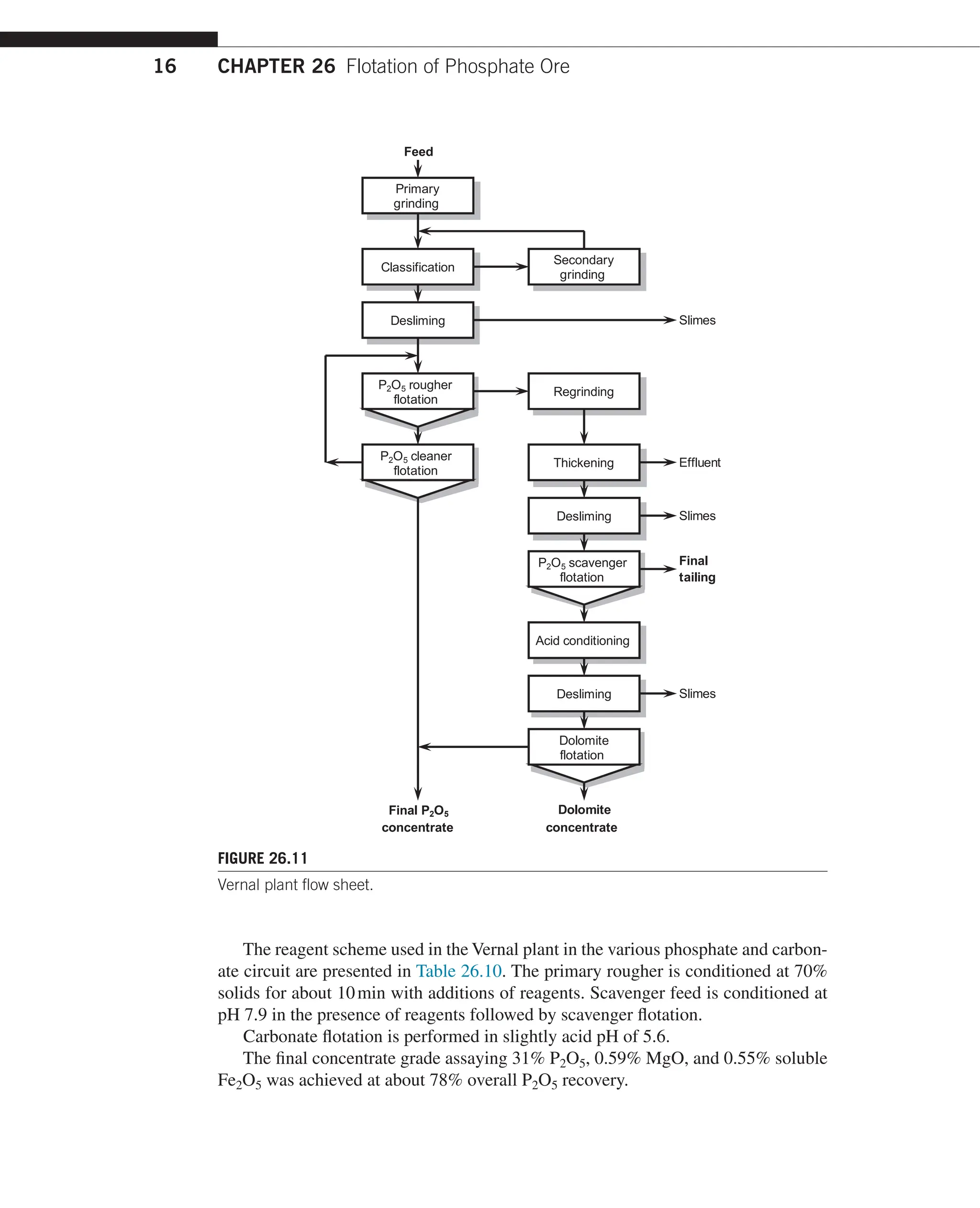
ore treated uses split circuit flow sheet, which included primary phosphate rougher
and cleaning followed by regrinding or rougher tailing and P2O5 scavenging.
The scavenger concentrate contains dolomite, which is removed by reverse flotation.
The plant flow sheet is presented in Figure 26.11.](https://image.slidesharecdn.com/handbook-of-flotation-reagents-chemistry-theory-and-practice-flotation-of-industrial-minerals-240217205157-8cbf963f/75/Handbook-of-flotation-reagents-_-chemistry-theory-and-practice-_-flotation-of-industrial-minerals-18-2048.jpg)
![CHAPTER 26 Flotation of Phosphate Ore
18
)HHG
32FOHDQHU
FRQFHQWUDWH
6OLPHV
0DJQHWLFV
7DLOLQJV
32 URXJKHU
IORWDWLRQ
*ULQGLQJ
ODVVLILFDWLRQ
0DJQHWLF
VHSDUDWLRQ
'HVOLPLQJ
RQGLWLRQLQJ
RQGLWLRQLQJ
32 VFDYHQJHU
IORWDWLRQ
32 FOHDQHU
32 FOHDQHU
32 FOHDQHU
VW
QG
UG
FIGURE 26.12
Generalized flow sheet used in Serrana plant.
References
[1]
Houot R, Joussemet R, Tracez J and Brouard R. Selective flotation of phosphatic ores hav-
ing a siliceous and/or carbonated gangue. Int J Mineral Process 1985;14:245–64.
[2]
Cleviei C, Norandini F, Mancini R. Flotation of phosphate rock with carbonate quartz
gangue. In: Jones MJ, Oblatt R, editors. Reagent in mineral industry. London: Ins. Min.
Met.; 1984. pp. 221–5.](https://image.slidesharecdn.com/handbook-of-flotation-reagents-chemistry-theory-and-practice-flotation-of-industrial-minerals-240217205157-8cbf963f/75/Handbook-of-flotation-reagents-_-chemistry-theory-and-practice-_-flotation-of-industrial-minerals-21-2048.jpg)
![19
References
[3]
Hanumantha K, Forssberg KSE. Pulp chemistry in apatite – sodium oleate – sodium sili-
cate flotation system: beneficiation of phosphate theory and practice. Society for Miner-
als, Metallurgy and Exploration Inc., Littleton, Co.; 1993.
[4]
Liang W, Zhang YW. A new process for beneficiation and concentration of sedimentary
phosphate in southwest China. In: Processing of IFA/CNCCC technical seminar on phos-
phate; 1983. pp. 17–36.
[5]
Smani SM, Blazy P, Cases JM. Beneficiation of sedimentary Moroccan phosphate ores.
Trans SME-AIME 1975;258(2):176–82.
[6]
Rule AR, Larson DA, Dallenbach CB. Application of calcite – silica flotation techniques
to western phosphate minerals. U.S. Bureau of Mines, R.I. No. 8728; 1982.
[7]
Lehr JR, Hsieh SS. U.S. Patent, 4,287,053; 1981.
[8]
Snow RE. U.S. Patent, 4,144,969; 1979.
[9]
Houot R, Polgarie JL. Inverse flotation beneficiation of phosphate ore. In: Proceedings of
the second international process on phosphate flotation; 1980. pp. 231–46.
[10]
U.S. patent 32,875; February 21, 1989.
[11] Bulatovic S. Laboratory investigation into recovery of apatite from Lalitpur, Uttar
Pradesh (India) Report No. 1; August 1985.
[12] Gong Wen Qi, Parentich A, Little LH and Warren LJ. Selective flotation of apatite from
iron oxides. Int J Mineral Process 1992;34:83–102.
[13] Bulatovic S. The recovery of apatite and ilmenite from apatite ilmenite ore, vols. 1 and
2; 1998. Report of Investigation – Lab and Pilot Plant.](https://image.slidesharecdn.com/handbook-of-flotation-reagents-chemistry-theory-and-practice-flotation-of-industrial-minerals-240217205157-8cbf963f/75/Handbook-of-flotation-reagents-_-chemistry-theory-and-practice-_-flotation-of-industrial-minerals-22-2048.jpg)
![21
Handbook of Flotation Reagents: Chemistry, Theory and Practice. http://dx.doi.org/10.1016/B978-0-444-53083-7.00002-6
Copyright © 2015 Elsevier B.V. All rights reserved.
CHAPTER
Beneficiation of
Beryllium Ores
27.1 Introduction
Most of beryllium production comes from beryl and therefore flotation properties of
beryl are examined in detail by various research organizations. Because beryl is found
in the form of large crystals in various ore types, recovery of beryl from these ores is
accomplished by sorting and or selective grinding due to the fact that the hardness of
beryl is 7.5–8 (Mohs scale); during grinding, most of the gangue is ground finer than
beryl and beryl is left in the coarse fraction, which is recovered by screening.
From the fine grained ore, beryl is recovered using the flotation method, where
either anionic or cationic flotation is used.
Very little is known about flotation of other beryllium minerals such as phenacite
and bertrandite. Research work carried out by some research organizations [1,2] on
complex phenacite-containing ores have shown that phenacite can be readily floated
using modified fatty acid. Using this method a concentrate grade assaying 40% BeO2
at 85% recovery was achieved.
27.2 Ore and minerals of beryllium
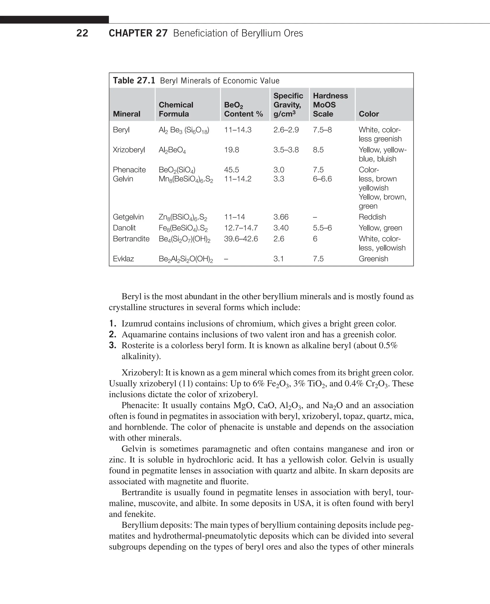
In nature, about 30 beryllium minerals are known of which six to eight have eco-
nomic value. The main beryllium minerals are presented in Table 27.1.
27
CHAPTER OUTLINE
27.1 Introduction�������������������������������������������������������������������������������������������������������21
27.2 Ore and minerals of beryllium�����������������������������������������������������������������������������21
27.3 Beneficiation of beryllium containing ores�����������������������������������������������������������24
27.3.1 Beneficiation of beryl�������������������������������������������������������������������24
27.3.2 Flotation of beryl=general overviews����������������������������������������������24
27.3.3 Flotation of beryl from pegmatite ores��������������������������������������������29
27.3.4 Flotation of bertrandite and phenacite��������������������������������������������31
27.3.4.1
Flotation of bertrandite and phenacite from Mount
Wheeler ore U.S.������������������������������������������������������������������ 34
27.3.4.2
Flotation of phenacite from complex beryllium,
yttrium and REO ore������������������������������������������������������������� 36
27.3.5 Operating plants��������������������������������������������������������������������������38
References�����������������������������������������������������������������������������������������������������������������40](https://image.slidesharecdn.com/handbook-of-flotation-reagents-chemistry-theory-and-practice-flotation-of-industrial-minerals-240217205157-8cbf963f/75/Handbook-of-flotation-reagents-_-chemistry-theory-and-practice-_-flotation-of-industrial-minerals-23-2048.jpg)


![27.3 Beneficiation of beryllium containing ores 29
Alkaline is added during grinding for high pulp density conditioning.
The ore treated at Bik-Auori (US) containing beryl, feldspar, quartz, orthoclas
with a little garnet and iron oxide is treated using an alkaline pretreatment method.
The ground deslimed ore is treated with 2.5kg/t NaOH after which the pulp is washed
by dilution and thickening. Beryl is floated using fatty acid made of koko oil. The
rougher concentrate is cleaned three times without reagents. From the ore containing
1.3% BeO, a concentrate assaying 12.2% BeO at 75% BeO recovery was produced.
Flotation tailings assayed 0.01% BeO but most of beryl losses occurred in a slime
fraction (i.e., 21% BeO).
When ores contain tourmaline and garnet with flotation properties better than
beryl, it is possible to prefloat tourmaline and garnet before beryl flotation using
small quantities of fatty acid. The tailings from tourmaline and garnet prefloat are
treated with either NaOH or Na2S and washed before beryl flotation. Beryl flotation
is performed using oleic acid at pH 9.5. The generalized flow sheet using the above
method is shown in Figure 27.5.
For depression of gangue minerals in some cases, Na2S is used, which has a
depressing effect on quartz, feldspar, and mica. In most cases using the alkaline
method, the pulp is deslimed before beryl flotation.
In some cases the pulp is heated to 85°C before beryl flotation, usually during
beryl flotation from bulk concentrate.
The alkaline flotation method has an advantage over the acid flotation method
due to the fact that the use of HF and H2SO4 is not required. In addition it is more
cost-effective.
The alkaline beneficiation method is most effective for ores that contain not only
quartz and feldspar but also talc chlorites and carbonaceous gangue. Talc, chlorite,
and carbonaceous gangue are first prefloated, followed by pulp pretreatment with
NaOH; desliming and beryl is floated using a fatty acid collector at pH 8.5–9.
27.3.3 Flotation of beryl from pegmatite ores
Development testwork on beryllium flotation from pegmatite ores has been carried
out over a considerable period of time [3–5]. A large portion of the world beryl pro-
duction comes from pegmatite ores. The pegmatite ore containing beryl also contains
feldspar, mica, spodumene, and ambligonite, some of which have similar flotation
properties as beryl.
In the research studies on the ore containing quartz, feldspar, mica, and beryl, the
two following flotation methods were investigated.
Method 1. This method consists of conditioning ground deslimed ore at 50% with
3000g/t Na2S followed by heating pulp to 85°C with 300g/t oleic acid. The pulp is
then diluted and beryl is floated.
Method 2. This method employs petroleum sulfonate as beryl collectors. Initially
mica was recovered using tallow amine acetate at pH 3.5 followed by beryl flotation
at pH 2.2 using a petroleum sulfonate collector. The results obtained using two flota-
tion methods are presented in Table 27.3.](https://image.slidesharecdn.com/handbook-of-flotation-reagents-chemistry-theory-and-practice-flotation-of-industrial-minerals-240217205157-8cbf963f/75/Handbook-of-flotation-reagents-_-chemistry-theory-and-practice-_-flotation-of-industrial-minerals-31-2048.jpg)


![CHAPTER 27 Beneficiation of Beryllium Ores
34
27.3.4.1 Flotation of bertrandite and phenacite from Mount
Wheeler ore U.S.
Detailed research work on this ore was conducted by the U.S. Bureau of Mines [6].
The studies were conducted on different ore grades assaying 0.47, 0.78, and 4.l7
BeO.
The procedure for selective flotation of the beryllium minerals from the gangue
minerals involves closely controlled preconditioning with sodium fluoride and
sodium hexametaphosphate. Collector used was a mixture of oleic acid with kerosene
fuel oil or turpentine.
The grade and recovery of beryllium from this ore was affected by (1) quantities
of HMP, (2) the HMP conditioning time, (3) collector conditioning time, and (4)
quantities of NaF. The effect of HMP conditioning time on beryllium flotation is
illustrated in Table 27.6.
Table 27.5 Metallurgical Results Obtained Using Bulk Spodumene/Beryl Alkaline
Flotation Method
Product Wt %
Assays % % Distribution
BeO Li2O BeO Li2O
Beryl concentrate 1.2 4.12 2.60 71.1 6.9
Spodumene concentrate 1.7 0.42 6.22 10.3 23.4
Hydro separation O/flow. 0.1 0.29 0.51 0.4 0.1
Thickener O/flow. 0.1 0.15 0.40 0.2 0.1
Beryl/Spodumene bulk
concentrate
3.1 1.84 4.44 82.0 30.5
Beryl/Spodumene tailing 85.0 0.011 0.10 13.5 18.8
Spiral class O/flow. 4.4 0.01 0.14 0.6 1.4
Spodumene scavenger
concentrate
3.6 0.061 5.85 3.1 46.7
Second hydrosep. O/flow. 3.9 0.014 0.30 0.8 2.6
Feed 100.0 0.069 0.45 100.0 100.0
Table 27.6 Effect of HMP Conditioning Time on Beryllium Grade and Recovery
HMP Conditioning
Minutes
Concentrate
Assays % BeO
Recovery %
BeO
10 7.6 47
20 14.5 77
30 16.5 75
40 9.3 89
50 8.0 90
60 7.0 91](https://image.slidesharecdn.com/handbook-of-flotation-reagents-chemistry-theory-and-practice-flotation-of-industrial-minerals-240217205157-8cbf963f/75/Handbook-of-flotation-reagents-_-chemistry-theory-and-practice-_-flotation-of-industrial-minerals-36-2048.jpg)

![CHAPTER 27 Beneficiation of Beryllium Ores
36
Table 27.7 Reagent Scheme and Metallurgical Results Obtained on Mount
Wheeler Ore
(a) Reagent Scheme
Reagent Additions, g/t
Sodium fluoride (NaF) 2100
Hexametaphosphate (HMP) 550
Collector 1 500
(b) Results
Wt %
Assays % Distribution
BeO CaCO3 % BeO
Concentrate 1 1.66 24.8 9.1 54.1
Concentrate 2 1.18 15.6 12.3 24.2
Combine concentrates 2.84 21.0 10.4 78.3
Final tail 97.16 0.17 – 21.7
Head (calc.) 100.0 0.76 – 100.0
Collector 1 is composed of four parts of oleic acid and four parts of terpene dissolved in
92% ethyl alcohol.
The results obtained in a continuous pilot plant operation are considered
satisfactory.
27.3.4.2 Flotation of phenacite from complex beryllium,
yttrium and REO ore
During 1980 an extensive research work was performed [7,8] on a complex beryl-
lium, yttrium, and REO ore with the objective of recovering high-grade phena-
cite concentrate. The Thor Lake (Canada) phenacite ore also contains appreciable
amounts of yttrium and rare earth elements. The main gangue minerals present in the
ore were feldspar, mica, various alumosilicates, quartz, and minor amounts of calcite,
dolomite, and magnetite.
Extensive laboratory development testwork was performed in which a number of
optional reagent schemes were examined including bulk phenacite feldspar flotation
followed by separation using sulfonate collectors for phenacite flotation. From the
reagent schemes examined, acid pretreatment followed by phenacite flotation using
fatty acid gave the best metallurgical results.
The treatment flow sheet developed for beneficiation of phenacite is shown in
Figure 27.9.
This flow sheet was used in the continuous pilot plant operation.](https://image.slidesharecdn.com/handbook-of-flotation-reagents-chemistry-theory-and-practice-flotation-of-industrial-minerals-240217205157-8cbf963f/75/Handbook-of-flotation-reagents-_-chemistry-theory-and-practice-_-flotation-of-industrial-minerals-38-2048.jpg)


![CHAPTER 27 Beneficiation of Beryllium Ores
40
References
[1] Fergus AJ, Sullivan GV, Workentine GF. Flotation characteristics of some beryllium min-
erals and associated gangue minerals. U.S. Bureau of Mines, Report of Investigation 7188;
March 1975. p. 26.
[2] Hareus R, Nisseu WI. Laboratory continuous flotation of bertrandite and phenacite from
Mount Wheeler, Nevada. U.S. Bureau of Mines, Report of Investigation 6386; June 1974.
[3] Ashton BE, Veiv LJ. Beneficiation of low-grade beryllium ore. First Report. South
Australia: Department of Mines; August 1961.
[4]
Trahar J. Flotation of beryl ore from Wedgina WA. Preliminary Report C.S.I. R.O
Melbourne Report No. 584, November 1959.
[5] Lamb FD. Beneficiation of New England, U.S. Beryl Ores. U.S. Bureau of Mines Report
on Investigation 4040; March 1961.
[6] Herans R, Nisseu WI. Laboratory and continuous studies of bertrandite and phenacite
from Mount Wheeler, Nevada. U.S. Bureau of Mines, Report on Investigation 6381; July
1963.
[7]
Bulatovic S. Process development for beneficiation of Thor Lake beryllium, yttrium, REO
ore. Report of Investigation, June 1985.
[8]
Bulatovic S. Pilot plant test on Thor Lake beryllium, yttrium, REO ore. Report on Investi-
gation, December 1986.](https://image.slidesharecdn.com/handbook-of-flotation-reagents-chemistry-theory-and-practice-flotation-of-industrial-minerals-240217205157-8cbf963f/75/Handbook-of-flotation-reagents-_-chemistry-theory-and-practice-_-flotation-of-industrial-minerals-42-2048.jpg)

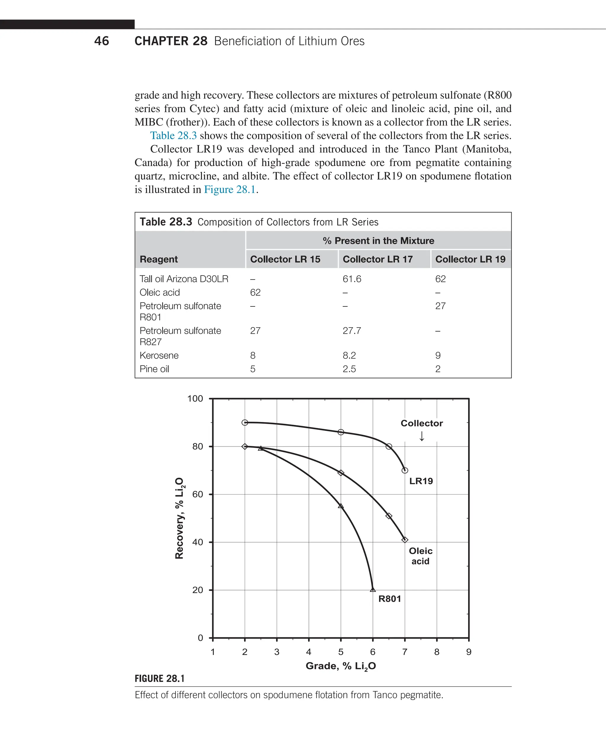
![CHAPTER 28 Beneficiation of Lithium Ores
42
of the mica and could, under acid flotation conditions lead to activation of other min-
erals in a flotation pulp.
Petalite: This is insoluble in acid and is a relatively stable mineral. In natural ores
it is usually found in a crystalline state. Petalite can be attacked by hydrofluoric acid.
The flotation properties of individual lithium minerals are significantly different
and largely dependent on the ore type and mineral composition of the ore.
28.2 Lithium ores and minerals
About 150 different lithium containing minerals are known and only 30 of these
contain significant quantities of lithium. They are represented by silicates and phos-
phates. Also the lithium minerals can exist as carbonates, sulfates, nitrates, wolfram-
ites, and others.
Of those, only five lithium minerals listed in Table 28.1 are of economic values.
Spodumene belongs to a silicate group and contains about 8% Li2O, 64.5% SiO2,
and 27.5% Al2O3. Spodumene is usually found in granite-pegmatites in the form of
crystals with different sizes and in association with quartz, mica amblygonite, beryl-
lium, and tantalum. Spodumene has a glossy, yellowish, or blue color. During the
process of formation of pegmatites, spodumene can be replaced by other minerals
like petalite quartz, albite, and muscovite.
Lepidolite and also zinvaldite contain less lithium as compared to spodumene.
Lepidolite is usually an unstable mineral, containing Al2O3 between 11.3% and
28.8%, SiO2 from 46.9 to 60.1, Li2O from 1.5% to 5.5%, and fluorite 9%. Lepidolite
contains rubidium up to 3.7% Rb2O and cesium about 1.5% Cs2O. The crystal struc-
ture is similar to that of muscovite and has a purple color.
Amblygonite is a lithium phosphate that contains up to 10% Li2O. However, it
has a secondary role in the production of lithium due to high phosphorus content.
The color of amblyonite is white to greenish. This minerals contains 54% P2O5, 34%
Al2O3, and up to 12% F.
Table 28.1 Lithium Minerals of Economic Values
Mineral Formula
Content % Li2O
SG, g/Cu3
Hardness
(MoOS)
Theoretical Actual
Spodumene LiAl [Si2O6] 8.1 4.5–8 3.2 6.5–7
Lepidolite KLi1.5Al1.5[Si3AlO10]
[F,OH]2
5.9 1.2–5.9 2.8–2.9 2–3
Amblygonite LiAl(PO4)(F1OH) or
Li2O3.2LiF.P2O5.Li2O
10.1 8–9.5 3–3.2 6
Zinvaldite KLiFeAl[Si3AlO10]
[F,OH]2
4.13 2–3 2.9–3.2 2–3
Petalite (Li,Na)AlSi4O11 4.89 2–4 2.39–2.46 6–6.5](https://image.slidesharecdn.com/handbook-of-flotation-reagents-chemistry-theory-and-practice-flotation-of-industrial-minerals-240217205157-8cbf963f/75/Handbook-of-flotation-reagents-_-chemistry-theory-and-practice-_-flotation-of-industrial-minerals-44-2048.jpg)

![CHAPTER 28 Beneficiation of Lithium Ores
44
28.3 General overview of beneficiation of lithium ore
The physical–chemical characteristics of lithium minerals are similar to that of
gangue minerals (i.e., quartz, feldspar, etc.) and therefore beneficiation of lithium is
sometimes a challenging task.
However flotation is a principal method for beneficiation of lithium minerals. In
recent years a new technology has been developed for flotation of spodumene, and
petalite. Using an innovative technology, a production of high-grade petalite concen-
trate was achieved (i.e., 4.6% Li2O) [1].
• Hand sorting is another concentration method and is used for the ore where
lithium minerals are in the form of large crystals and also utilizes the color
difference between lithium and gangue minerals. This process is practical for
beneficiation of petalite ores (Zimbabwe, Africa, and China).
• Heavy liquid separation is mostly for the beneficiation of spodumene ore. This
method is based on specific gravity differences between spodumene (3.2g/Cu3)
and gangue minerals (2.6–2.7g/Cu3). Heavy liquid preconcentration can also be
used in combination with flotation.
• Thermal treatment (decapitation) is sometimes used for concentration of spodu-
mene ores. The ore is heated to 95–1000°C, where the spodumene is converted
from α to β form in which case spodumene is transferred to powder form and is
separated from other minerals either by screening or by air classification.
Magnetic separation is used for recovery of zinvaldite, which contains about
0.5% FeO.
28.4 Flotation properties of different lithium minerals
28.4.1 Flotation properties of spodumene
Flotation properties and selection of flotation methods very much depends on the type of
gangue minerals present in the ore. Flotation properties of spodumene was also affected
by the presence of heavy metals cations (i.e., iron). Over the years extensive research
work has been conducted on various ore types. Studies were conducted on beryllium-
spodumene ore [2]. In these studies oleic acid was used to float spodumene from beryl.
The method comprised of pulp pretreatment with sodium hydroxide followed by deslim-
ing before collector conditioning at elevated temperature (80–85°C). Using this method
it was possible to selectively float spodumene from beryl and other gangue minerals.
During beneficiation of various spodumene containing ores, pulp pretreatment
before spodumene flotation is very important. This has been confirmed by a number
of researchers [3]. Pretreatment of pulp is performed by two methods, these are:
(1) conditioning pulp at 50–60% solids in the presence of 0.5 to 1kg/t NaOH for
20–30min. The NaOH was added in stages at 10min intervals. After surface treat-
ment the pulp was deslimed following spodumene flotation using oleic acid (400–
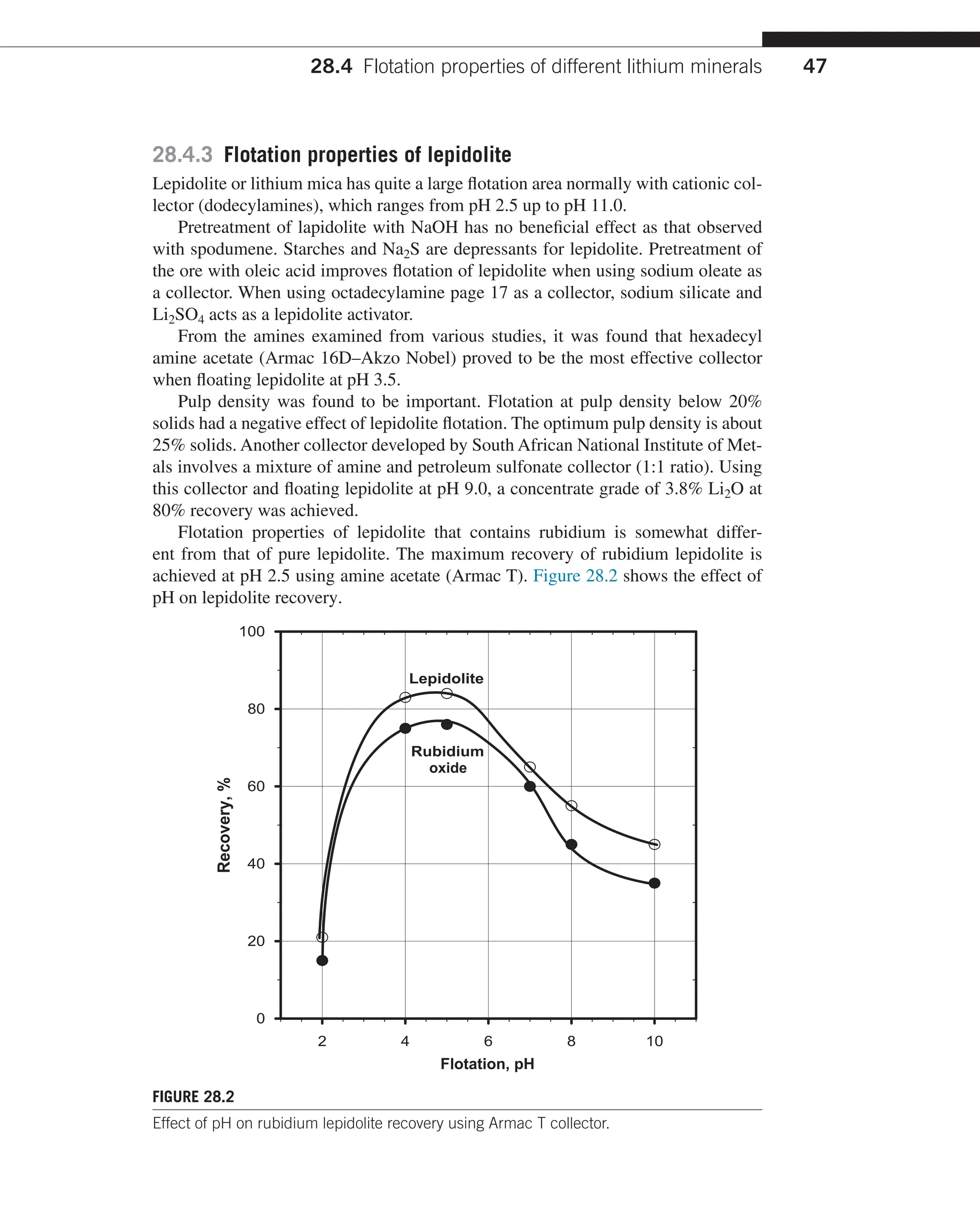
600g/t). (2) The use of Na2S in the pretreatment stage also gave good metallurgical](https://image.slidesharecdn.com/handbook-of-flotation-reagents-chemistry-theory-and-practice-flotation-of-industrial-minerals-240217205157-8cbf963f/75/Handbook-of-flotation-reagents-_-chemistry-theory-and-practice-_-flotation-of-industrial-minerals-46-2048.jpg)
![28.4 Flotation properties of different lithium minerals 45
results in the subsequent flotation stage. Oleic acid was found to be the best collector
for spodumene flotation.
With South Dakota ore (US) using NaOH pretreatment followed by desliming
and spodumene flotation using oleic acid concentrate grade assaying 7.2% Li2O at
75% recovery was achieved in a pilot plant test.
During the treatment of pegmatite ore that contained spodumene, mica, feldspar,
and quartz, two methods have been developed by Cytec.
Cytec research laboratories. In both methods the ground ore was scrubbed at 20%
solids in the presence of 2kg/t NaOH for 20min. The scrubbed pulp was deslimed.
In one method an initial removal of mica was carried out using amine collector
at pH 2.5 to 3.0. The mica tailing is dewatered followed by conditioning with oleic
acid at 50% solids. After collector conditioning, the pulp was diluted to 20% solids
and spodumene rougher flotation was performed followed by two cleaning stages.
Using this method a concentrate grade assaying 5.0% Li2O at only 45% recovery
was achieved.
The second method examined was more successful, involving first spodumene
flotation following acid conditioning of the deslimed pulp at 64% solids with 500g/t
oleic acid. The rougher float was performed at about 28% solids. Rougher concen-
trate was cleaned twice also in the acid circuit. Using this method, a concentrate
grade assaying 7.2% Li2O at 90% Li2O recovery was achieved.
Another pretreatment method used for recovery of spodumene from weathered
pegmatite involves grinding the ore in the presence of NaF soda ash and Cytec
depressant 610 (modified sulfonate) followed by scrubbing with extra additions of
NaF and depressant 610 and desliming. The deslimed pulp was conditioned with
Aero 765 (mixture of oleic and linoleic acid) and spodumene rougher and two clean-
ing stage was performed. Using this method about 80% Li2O was recovered in a
concentrate assaying 5% Li2O.
In treatment of North Carolina beryl-containing pegmatite, a method involving
conditioning ground ore with NaF and liquid sulfonate followed by washing and
desliming was performed. The deslimed pulp was conditioned with oleic acid and
spodumene was floated at pH between 6.5 and 8.0. Using this method about 80%
Li2O was recovered at a concentrate grade assaying 6.5% Li2O. The method involv-
ing reverse gangue flotation was examined on the ore containing quartz, feldspar,
and mica using cationic collector (Armac T-lauryl amine acetate) in conjunction with
sodium hydroxide dextrin and pine oil. Using this method most of the mica and
quartz together with a portion of feldspar was recovered and cell product containing
about 6% Li2O at 78% Li2O recovery was obtained.
28.4.2 Research and development of the new spodumene
flotation system
During the 1980s and early 1990s extensive research work was carried out on various
spodumene containing ores from Canada [4,5]. As a result, a highly effective col-
lector system has been developed, which is capable of producing a high concentrate](https://image.slidesharecdn.com/handbook-of-flotation-reagents-chemistry-theory-and-practice-flotation-of-industrial-minerals-240217205157-8cbf963f/75/Handbook-of-flotation-reagents-_-chemistry-theory-and-practice-_-flotation-of-industrial-minerals-47-2048.jpg)
![CHAPTER 28 Beneficiation of Lithium Ores
48
In these experiments a concentrate grade of 3.6% Li2O at 85% Li2O recovery was
achieved. Concentrate assayed 3.2% Rb2O3.
28.4.4 Flotation properties of petalite
Very little data exist in literature on flotation of petalite. It has been claimed
that good flotation of petalite was obtained with the dodecylamine collector, with
very little sensitivity to change in pH between 2.0 and 11.0. This is not the case
in treating complex pegmatite ores that contain feldspar, lepidolite, mica, and
albite. With this ore using dodecylamine as the collector and with pH varying
between 2.0 and 8.0 no selective flotation of petalite was achieved [6]. Table 28.4
shows metallurgical results obtained in the laboratory using dodecylamine and
various pH.
Extensive research conducted on the same ore resulted in the development of
a new treatment process that produces a concentrate grade of 4.7% Li2O at 85%
petalite recovery [7]. The reagent scheme and the metallurgical results obtained
on complex petalite ore are shown in Table 28.5(a and b).
In these experiments first mica is recovered followed by spodumene flotation.
This was lithium mica and also contains significant quantities of rubidium. The flow
sheet used in these experiments is shown in Figure 28.3 below.
28.5 Plant practices in beneficiation of
lithium bearing ores
The lithium ores and operating plants are found in Australia, Canada, and United
States. In the other parts of the world lithium is found in China, Africa (petalite
ore), and Brazil. Treatment options of spodumene and petalite largely depends on
the gangue composition present in the ore. If the ore contains mica and talc, then
these are floated ahead of spodumene. Several processing plants of importance are
deslimed in this section.
Table 28.4 Effect of pH on Petalite Flotation from Separation Rapids (Canada)
Pegmatite Ore Using Dodecylamine Collector
Collector
Additions,
g/t
Flotation
pH
Cleaner Concentrate Rougher Concentrate
Assays %
Li2O
Distribution
% Li2O
Assays %
Li2O
Distribution
% Li2O
450 2.0 2.20 45 1.5 56
450 4.0 2.33 42 1.4 55
450 8.0 2.18 35 1.2 50
700 2.0 2.40 50 1.7 66
700 4.0 2.35 52.0 14.6 64](https://image.slidesharecdn.com/handbook-of-flotation-reagents-chemistry-theory-and-practice-flotation-of-industrial-minerals-240217205157-8cbf963f/75/Handbook-of-flotation-reagents-_-chemistry-theory-and-practice-_-flotation-of-industrial-minerals-50-2048.jpg)

![CHAPTER 28 Beneficiation of Lithium Ores
50
28.5.1 Bernic Lake—Manitoba, Canada
The Bernic Lake ore is relatively complex and variable within the ore body. The
main minerals include quartz, feldspars, microcline, albite, and lepidolite. Major lith-
ium minerals are spodumene with some amblygonite. The amblygonite represents a
problem in recovery of spodumene as this mineral contains phosphorus, which is an
impurity in production of high-grade spodumene. Initial development work started in
1978, which included pilot plant testing. Plant production was started in 1984. In the
treatment flow sheet, heavy media separation was included [8]; also preflotation of
amblygonite before lithium flotation. The plant flow sheet is illustrated in Figure 28.4.
The metallurgical results obtained with heavy media separation are shown in
Table 28.6. Approximately about 35.9% weight was rejected in the float product which
contained only 3.1% Li2O of the feed. The triflow was used for heavy media separation.
Feed
s
e
m
i
l
S
s
e
m
i
l
S
High grade petalite
concentrate
4.6–4.8% Li2O
e
n
e
m
u
d
o
p
S
r
e
n
a
e
l
c
a
c
i
M
e
t
a
r
t
n
e
c
n
o
c
e
t
a
r
t
n
e
c
n
o
c
Medium grade Final
concentrate tailings
3.8–4.0% Li2O
Grinding
Conditioning 1
Desliming
Mica rougher
flotation
Mica cleaner
flotation
Conditioning 2
Conditioning
Conditioning
Desliming
Spodumene
rougher flotation
Spodumene
cleaner flotation
Conditioning
Petalite rougher
flotation
Petalite cleaner
flotation
Conditioning
Scalping rougher
flotation
Scalping cleaner
flotation
FIGURE 28.3
Flow sheet for beneficiation of petalite from complex ores using flotation.](https://image.slidesharecdn.com/handbook-of-flotation-reagents-chemistry-theory-and-practice-flotation-of-industrial-minerals-240217205157-8cbf963f/75/Handbook-of-flotation-reagents-_-chemistry-theory-and-practice-_-flotation-of-industrial-minerals-52-2048.jpg)

![CHAPTER 28 Beneficiation of Lithium Ores
52
The concentrate grade on average was about 7.2 Li2O and sometimes reached
about 7.7% Li2O.
28.5.2 Lithium, Australia—Greenbushes operation
The Greenbushes is a major producer of lithium in the world. There are two ore bod-
ies including tantalum/niobium and tin and the lithium ore body. The ore reserves are
about 30milliontonnes, containing at least 7milliontonnes at 4.0% Li2O [9].
The processing plant produces glass-grade concentrate and high-grade concen-
trate. The processing flow sheet is shown in Figure 28.5.
The ore is crushed to 16mm nominal size. The ore is fed to a ball mill. The ball
mill discharge is classified into 15 columns, where 250μm fraction is removed to
provide feed for desliming and flotation.
The plus 250μm fraction is screened on 800μm screen. The plus 800μm material
is recycled to a ball mill and plus 800μm fraction is subjected to a magnetic separa-
tion. The nonmagnetic fraction is glass grade spodumene assaying about 6.5% Li2O.
The minus 250μm fraction is deslimed to remove minus 20μm slime followed by
bulk spodumene tourmaline flotation using fatty acid collectors and soda ash for pH
control (pH of 7.0–7.5). The bulk concentrate is treated by gravity followed by mag-
netic separation to remove tourmaline. Magnetic separation is done at 0.9T magnetic
field strength.
The concentrate grade after magnetic separation assayed 7.5–7.7% Li2O and less
than 0.1% Fe2O3.
Table 28.6 Plant Heavy Media Separation Test Results
Product Wt %
Assays % % Distribution
Li2O Na2O K2O Li2O Na2O K2O
Sink 1 53.4 5.41 0.38 0.14 83.0 23.2 2.2
Sink 2 10.7 4.50 0.53 0.31 13.9 6.5 10
Combined sinks 64.1 5.26 0.41 0.17 96.9 29.7 3.2
Float 35.9 0.30 1.71 9.15 3.1 70.3 96.8
Feed 100.0 3.48 0.87 3.39 100.0 100.0 100.0
Table 28.7 Projected Plant Metallurgical Results
Product Wt %
Assays % % Distribution
Li2O P2O5 Li2O P2O5
Li2O Cl. concentrate 37.46 7.10 0.05 82.4 10.05
P2O5 comb. concentrate 2.74 5.28 4.47 4.49 65.88
Li2O Cl. tails 11.70 2.64 0.05 10.02 3.28
Scavenger tail 47.39 0.18 0.08 2.65 20.36
Slimes 0.77 2.03 0.11 0.48 0.43
Feed 100.00 3.22 0.20 100.00 100.00](https://image.slidesharecdn.com/handbook-of-flotation-reagents-chemistry-theory-and-practice-flotation-of-industrial-minerals-240217205157-8cbf963f/75/Handbook-of-flotation-reagents-_-chemistry-theory-and-practice-_-flotation-of-industrial-minerals-54-2048.jpg)


![CHAPTER 28 Beneficiation of Lithium Ores
56
References
[1]
Jessup T, Bulatovic S. Recovery of petalite from ores containing feldspar minerals. U.S.
Patent 6,138.835; October 31, 2000.
[2] Arbiter N, Abshiev JR, Crawford JW. Attritioning and conditioning in flotation of spodu-
mene ore quartz, vol. 56. Colorado School of Mines; July 1961. p. 321–32.
[3] Browning JS, McVay TL. Beneficiating spodumene from pegmatites, from Gaston County,
N.C. USBM Report, Invest; 1961. 5756.
[4] Bulatovic S. Process development for beneficiation of spodumene, from Bernic Lake,
Manitoba, Canada Report of Investigation. June 1981. p.180.
[5] Bulatovic S. Research and development on spodumene flotation from various ores Report
on Investigation. January 1983. p. 111.
[6] Jessup T, Bulatovic S. Preliminary process development on petalite beneficiation using
flotation method. SGS Report on Investigation; October 2001. p. 250.
[7]
Bulatovic S. New process developed for beneficiation of petalite using flotation method
2003.
[8] Burt RO. Gravity concentration technology. Amsterdam: Elsevier; 1984. p. 606.
[9] Bale MD, May AV. Processing of ores to produce tantalum and lithium. Miner Eng
1989;2(3):299–320.](https://image.slidesharecdn.com/handbook-of-flotation-reagents-chemistry-theory-and-practice-flotation-of-industrial-minerals-240217205157-8cbf963f/75/Handbook-of-flotation-reagents-_-chemistry-theory-and-practice-_-flotation-of-industrial-minerals-58-2048.jpg)


![29.3 Research and development in beneficiation of fluorite ores 59
29.3 Research and development in beneficiation
of fluorite ores
29.3.1 Introduction
Over the past 30years extensive research work was carried out on various fluorite
containing ores, in which other alternative reagent schemes including collectors and
depressant systems were examined. The ores that are most difficult to treat are car-
bonaceous ores as well as disseminated fluorite-silicate ores and ores that contain
barite.
From the processing point of view, the flotation properties of fluorite ore are
similar to those of gangue minerals present in the ore (i.e., calcite dolomite, borite);
therefore application of selective reagent schemes is essential for production of high-
grade fluorspar concentrate. Fluorspar ore varies widely in its amenability to concen-
tration using flotation techniques or combinations of gravity and flotation. Based on
minerals and gangue composition and amenability to concentration [1], the different
ore types can be divided into the following groups.
1.
Siliceous nonalkaline earth ores in granite or granodiorite rocks. These ores,
common in US, South Africa, and Mexico are disseminated, and grinding to
liberation is the main problem in treating this ore type.
2.
Siliceous ore with alkaline earth, consisting mainly of limestone and calcite.
These ores carry lead, zinc, and other sulfides. In beneficiation of these ores,
sulfides are recovered ahead of fluorspar flotation.
3.
Baritic alkaline earth siliceous ores with sulfides where sulfides were recov-
ered first followed by fluorspar flotation and barite depression. Standard barite
depressants are dextrin, starches, or chromates.
4.
Weathered alkaline earth ores with mica and residues of sulfide oxidation.
In beneficiation of these ores, mica is recovered first followed by fluoride
flotation.
29.3.2 Summary of the research and development—depressants
and modifiers
Research work in treatment of fluorspar ores dates back to 1940 [2], and is
conducted nowadays. Literature on beneficiation of fluorspar ore is extensive
and includes a new development, such as new collectors, modifiers, and
depressants.
29.3.2.1 Acidified silicates
In treatment of carbonatite ore, studies were conducted using acidified silicates [3].
It has been demonstrated that acidified silicate has an activating effect on fluorite,
while it improves selective depression of calcite. A degree of acidification plays an
important role in production of acid grade fluorspar. Figure 29.1 shows the effect of
the degree of acidification on fluorspar concentrate grade.](https://image.slidesharecdn.com/handbook-of-flotation-reagents-chemistry-theory-and-practice-flotation-of-industrial-minerals-240217205157-8cbf963f/75/Handbook-of-flotation-reagents-_-chemistry-theory-and-practice-_-flotation-of-industrial-minerals-61-2048.jpg)
![CHAPTER 29 Beneficiation of Florite Ores
60
29.3.2.2 Modified copper sulfate
In the ores that contain phosphate, effective removal of phosphate [4] was achieved
with the use of sodium chlorite (NaCl)-modified copper sulfate. The modified copper
sulfate was prepared as follows:
First, 1% CuSO4 solution and 2% NaCl is prepared separately in the same vol-
ume. At a solution temperature of 55°C, the CuSO4 solution is slowly added into
the NaCl solution while slowly mixing to obtain CaCl-modified CuSO4. The effect
of modified CuSO4 on phosphate removal from fluorite concentrate is illustrated in
Figure 29.2.
29.3.2.3 Soda ash—quebracho system
Quebracho is used during fluorspar flotation as a selective depressant for calcite and
limestone. Effectiveness of quebracho very much depends on the level and point
of additions [5,6]. Higher addition of quebracho in the flotation improves fluor-
spar grade but reduces recovery. Table 29.1, shows the effect of levels of quebracho
additions to the cleaners on fluorspar grade and recovery.
Different levels of quebracho were also examined during fluorspar rougher flota-
tion using calcite dolomite ore. In these tests distilled oleic acid was used as a collec-
tor and Na2CO3 for pH control. With increasing levels of quebracho in the fluorspar
rougher flotation stage, the concentrate grade increased while the fluorspar recovery
was reduced (Figure 29.3). It has been determined by different researchers [7] that
FIGURE 29.1
Effect of degree of silicate acidification on fluorspar flotation from carbonaceous gangue.](https://image.slidesharecdn.com/handbook-of-flotation-reagents-chemistry-theory-and-practice-flotation-of-industrial-minerals-240217205157-8cbf963f/75/Handbook-of-flotation-reagents-_-chemistry-theory-and-practice-_-flotation-of-industrial-minerals-62-2048.jpg)

![CHAPTER 29 Beneficiation of Florite Ores
62
FIGURE 29.3
Effect of the level of quebracho additions on fluorspar rougher flotation.
Starches and/or dextrins are used in the treatment of most of the fluorspar ore
types including siliceous ores, calcite silicate containing ores, barite containing ores,
and sulfide containing ores. Types of starches and dextrins and their preparation
method play an important role in their efficiency.
For example, causticized and boiled starches perform better than ordinary pre-
pared starches. Branched dextrins are more efficient that standard unbranched dex-
trin. Studies were conducted on ores that contain calcite and quartz as main gangue
minerals in which different starches and dextrins were examined [8]. The effects of
different starches and dextrins on fluorspar flotation are presented in Table 29.2.
As can be seen from the results, the highest concentrate grade was achieved using
either boiled caustic cornstarch or caustic potato starch.
29.3.2.5 Other depressants and modifiers
In beneficiation of fluorspar ore a number of secondary depressants and modifiers
are used. Following is a brief description of the individual secondary depressants and
modifiers:
1.
Sodium fluorosilicate (Na2SiF6) is used in the treatment of barite containing
fluorspar ore as a barite depressant. It also improves silica rejection.
2.
Ligninsulfonate is sometimes used in place of quebracho in the treatment of
barite containing ore; It improves barite depression.](https://image.slidesharecdn.com/handbook-of-flotation-reagents-chemistry-theory-and-practice-flotation-of-industrial-minerals-240217205157-8cbf963f/75/Handbook-of-flotation-reagents-_-chemistry-theory-and-practice-_-flotation-of-industrial-minerals-64-2048.jpg)

![CHAPTER 29 Beneficiation of Florite Ores
64
The type of fatty acid plays an important role in both selectivity and recovery of
fluorspar [9,10]. Testwork with different fatty acids were performed on the ore that
assayed 31.5% CaF2. The results obtained are summarized in Table 29.3.
The best concentrate grade was obtained using a mixture of oleic/linolenic acid
and with distilled oleic acid. Using tall oil fatty acid high CaF2 recovery was achieved
but with reduced concentrate grade.
In recent years, a new more selective collector was developed for the treatment
of complex fluorspar ores. Some of these collectors and its effectiveness are sum-
marized as follows:
•
Oleyl sarcosine is examined on the ore that contains a relatively high amount of
calcite. It has been reported that a remarkable improvement in the metallurgical
result [11] were achieved with new fluorite collector oleyl sarcosine (N-oleoyl-
N-methyl-amino carboxylic acid with the formula:
C17H33 - C-N-CH2-COOH
II I
C CH3
This collector is known as Cordezin O. This collector is being used in Ilmenau
concentrator (Germany).
FIGURE 29.4
Effect of saponified and emulsified fatty acid on fluorspar flotation.](https://image.slidesharecdn.com/handbook-of-flotation-reagents-chemistry-theory-and-practice-flotation-of-industrial-minerals-240217205157-8cbf963f/75/Handbook-of-flotation-reagents-_-chemistry-theory-and-practice-_-flotation-of-industrial-minerals-66-2048.jpg)
![29.3 Research and development in beneficiation of fluorite ores 65
•
Sodium naphthenate collector was examined using the fluorspar ore from the
Fenglin plant (North China). The commercial name of the collector is GY-2 and
is composed of 33.13% sodium naphthenate, 6.63% fatty acid, and 51% water.
This collector is produced by mixing a by-product from the oil refinery with
fatty acid. This collector comes with the carbon numbers between C3 and C6
carbons.
•
In the study it was found that the number of carbons determines the fluorspar
recovery. Figure 29.5 shows the effect of hydrocarbon number on fluorite
recovery.
The higher number of carbon improves CaF2 recovery significantly.
•
Collectors from AK-F Series were developed recently for beneficiation
of refractory fluorspar ores that contain, in addition to calcite, clay, and
iron oxides. Collector AK-F2 is composed of the following individual
reagents [12].
Oleic acid (FAl) = 38%
Phosphate ester (AEP) = 42%
Ethylene diamine = 20%
This collector was developed for beneficiation of the ore from India. The
effectiveness of this collector is illustrated in Table 29.4 where comparative con-
tinuous locked cycle tests were performed using emulsified oleic acid and col-
lector AK-F2.
A significant improvement in fluorspar metallurgical results was achieved with
the use of the new collector as compared with the standard oleic acid collector.
Table 29.3 Effect of Different Types of Fatty Acids on Fluorspar Grade and
Recovery
Fatty Acid Type
Assays %
Recovery % CaF2
CaF2 SiO2
Oleic acid (Arizona FA3) 20%
rozin acid
94.2 2.1 89.5
Oleic/linolenic acid (1:1) L-5 98.5 0.7 81.2
Distilled oleic acid (Arizona FA) 96.2 0.9 84.5
Fatty acid mixture (Soliflot 50A) 95.7 1.1 85.8
Tall oil fatty acid (D30LR) 30%
rozin acid
90.2 3.3 89.3
Undistilled fatty acid (Hercules) 94.9 1.3 86.3](https://image.slidesharecdn.com/handbook-of-flotation-reagents-chemistry-theory-and-practice-flotation-of-industrial-minerals-240217205157-8cbf963f/75/Handbook-of-flotation-reagents-_-chemistry-theory-and-practice-_-flotation-of-industrial-minerals-67-2048.jpg)


![75
References
References
[1]
Fulton RB, Montgomery G. “Fluorspar and cryolite”, industrial minerals and rocks.
5th ed. New York: AIME; 1983.
[2]
Taggart FF. Attritioning handbook of mineral dressing. New York: John Wiley; 1945.
[3]
Zhou Q, Lu S. Acidified silicate – an effective modifier in fluorite flotation. Mineral Eng
1992;5:435–44.
[4]
Zhang Y, Song S. Process beneficiation of fluorite in a new chemical scheme. Mineral
Eng 2003;16:597–600.
[5]
Harman FH, Wyman RA. Beneficiation of fluorite, from Udaipur, India, Department of
Mines and Technical Survey, Ottawa, Canada. Report of Investigation 1R, 66–3.
[6]
Browning JS, Eddy WH, McVay TL. Selective flotation of barite – fluorspar ore from
Kentucky. Report of Investigation 6187. AUS Bureau of Mines; 1963.
Table 29.8 Reagent Scheme Used in Flotation of Mixed Sulfide Fluorspar Ore
Reagent
Additions, g/t
Lead Pyrite Circuit Zinc Circuit Fluorspar Circuit
Sodium ethyl. xanthate 20–40 – –
Methyl Isobutyl
Carbanol (MIBC) frother
5–10 5–10 –
Zinc sulfate 300–500 – –
Copper sulfate – 200–400 –
Aeroflot 211 – 30–60 –
Soda ash – – 800–1200
Sodium silicate – – 600–800
Quebracho – – 600–800
Caustic starch – – 200–400
Fatty acid emulsifier – – 200–300
Table 29.9 Chemical Compositions of Commercial Acid–Grade Fluorspar
Element
Assays
Italy Mexico
South
Africa Morocco Spain UK USA
CaF2 (%) 97.58 97.52 97.58 98.23 97.56 97.60 97.80
SiO2 (%) 0.75 0.89 0.84 0.57 0.98 0.40 0.62
CaCO3 (%) 0.68 0.79 0.30 0.66 0.75 1.30 1.33
Total S (%R) 0.14 0.036 0.004 0.022 – – –
Sulfide S (%) 0.015 0.013 0.002 0.014 0.013 – 0.028
Arsenic (ppm) 10 300 3.0 1.0 10 2 1.0
P2O5 (ppm) 160 540 320 50 180 0.5 0.0
NaCl (ppm) 140 40 170 200 180 – –](https://image.slidesharecdn.com/handbook-of-flotation-reagents-chemistry-theory-and-practice-flotation-of-industrial-minerals-240217205157-8cbf963f/75/Handbook-of-flotation-reagents-_-chemistry-theory-and-practice-_-flotation-of-industrial-minerals-77-2048.jpg)
![CHAPTER 29 Beneficiation of Florite Ores
76
[7]
Iskra J, Guttieve LC, Kitchener JA. Influence of quebracho on the flotation of fluorite,
calcite, hematite and quartz. Trans IMM 1973;9:219.
[8]
Bulatovic S. Process development for beneficiation of fluorite ore from Kentucky US
Report of Investigation; July 1989.
[9]
Marinakis KI, Shergold HL, Kitchener JA. The mechanism of fatty acid adsorption on
fluorite, calcite and barite. Int J Miner Process; 1982;14:161–176.
[10] Bulatovic S. Effect of type of fatty acid on fluorspar flotation, from Newfoundland cal-
cite, silicate fluorspar ore Report on Investigation; March 1996.
[11] Schubert H, Baldauf H, Kramer W. Further development in fluorite flotation from
the ores higher calcite contents with oleoylsarcosine as collector. Int J Miner Process
1990;30:185–93.
[12] Bulatovic S. Beneficiation process development for Indian refractory fluorspar ore
Report of Investigation; September 1996.](https://image.slidesharecdn.com/handbook-of-flotation-reagents-chemistry-theory-and-practice-flotation-of-industrial-minerals-240217205157-8cbf963f/75/Handbook-of-flotation-reagents-_-chemistry-theory-and-practice-_-flotation-of-industrial-minerals-78-2048.jpg)

![CHAPTER 30 Wollastonite
78
Idocrase=Ca10Al4(MgFe)2(Si2O7)(SiO4)5(OH)4
Grossulat Garnet=Ca3Al2(SiO4)3 and
Andradite Garnet=Ca3Fe(SiO4)3
Wollastonite is found in silicated metalimestone that has been affected by regional
metamorphism or local igneous activity. Deposits of sufficient size and purity are
rare.
In a pure state, wollastonite has the following properties:
Hardness (Mohs scale)=4.5–5.0
Specific gravity (g/cc)=2.8–3.09
Moisture content=4.0 Max
Retroactive index=1.616–1.631
Crystal system=monoclinic
Common form=masses of aggregates of bladed or needle-like crystals
Luster=vitreous, transparent to translucent.
Although the mineral is white when being pure, it is often colored, gray, or brown
due to impurities and it is the nature of these impurities, which determine whether the
mineral is economically exploitable.
Because of the complex nature of the ore, the production of wollastonite is limited.
30.3 Beneficiation of wollastonite ore
There are three main methods by which wollastonite is concentrated, these include:
1. Mechanical sorting;
2.
Magnetic separation dry or wet;
3.
Flotation—a/u? Combination of physical separation and flotation. In some
cases, combinations of magnetic separation and flotation are used.
30.3.1 Mechanical sorting
The mechanical sorting of the ore is applicable if in case wollastonite is present in the
ore in the form of large crystals. The wollastonite from the host rock is separated by
hand cobbing, the product being marketed in lump form.
Hand cobbing was practiced in the early 1970s in Finland and some operations
in China and Romania.
30.3.2 Dry or wet magnetic separation
Wet magnetic separation [1] has been evaluated on several deposits from New York,
US. Using a pilot plant, finely ground unsized wollastonite ore is diluted in water and
passed through a high intensity oscillating wet magnetic separator of special design and
in a single pass over 90% wollastonite exhibiting crystal purity of 99% was obtained.
The product was then ground and sized to obtain products of different sizes.](https://image.slidesharecdn.com/handbook-of-flotation-reagents-chemistry-theory-and-practice-flotation-of-industrial-minerals-240217205157-8cbf963f/75/Handbook-of-flotation-reagents-_-chemistry-theory-and-practice-_-flotation-of-industrial-minerals-80-2048.jpg)

![CHAPTER 30 Wollastonite
80
30.3.3 Flotation methods research and development
Because wollastonite forms needle-like crystals selective flotation of wollastonite
from gangue minerals is rather difficult. Reverse gangue flotation or bulk flota-
tion followed by separation of wollastonite from gangue minerals is often prac-
ticed. For example, in the ores that contain calcite minerals, calcite is first floated
using sulfate soap followed by gangue flotation (i.e., silica, feldspar) using amine
flotation.
In the Romania Research Institute, development work was carried out on iron
containing ore [2,3] and the ore that contained garnet diopside and epidote. In
the case of iron containing ore, the ground ore was subjected to single-stage
magnetic separation followed by reverse gangue flotation using sulfate soap
collector. Using this method a wollastonite with 95% purity at 86% recovery was
achieved.
The ore that contains garnet diopside and epidote was treated by using reverse
gangue flotation.
The ground ore is conditioned with sulfuric acid to pH 6–6.5 and the gangue
minerals are floated using sulfate soap collector (i.e., sodium dodecyl sulfate).
The ore that contains mostly calcite with some quartz and iron silicate is pro-
cessed as follows.
The ground ore is first conditioned with fatty acid followed by calcite flotation.
The calcite tailing was deslimed followed by silicate flotation using a mixture of
anionic and cationic collector [4].
Some research work was carried out by the Russian Institute SAIGIMS. The ore
that contains about 70% wollastonite, 20% mixture of feldspar, and 7% pyroxene
with minor amounts of quartz and calcite was treated using reverse gangue flotation.
First calcite was floated under alkaline conditions with tallow soap or saponified
naphthenic acid collector.
The calcite tailing was treated with sulfuric acid and feldspar was floated using
collector ANP-14 (amine).
In the final stage, pyroxenes were removed using a soap collector together with
600g/t lead nitrate as an activator. Using this method a wollastonite concentrate
assaying 92% wollastonite at 81% recovery was produced. The flow sheet using
reverse flotation process is shown in Figure 30.2.
Research and development work on Canadian ore that contains feldspar,
quartz, and diopside was conducted using air classification where a portion of
fine gangue was recovered followed by bulk wollastonite–diopside flotation and
wollastonite–diopside separation. The flow sheet used in this separation is shown
in Figure 30.3. In preparation of the ore, the crushed ore is dried and ground in a
roll crusher. The fines of about 10-mesh size are treated in an air classifier where
a portion of coarse fraction is returned to the roll crusher. The fines were flotation
feed. Initially, wollastonite and diopside were floated using collector SM15 (phos-
phoric acid ester) in alkaline pH, the concentrate was cleaned twice, followed
by conditioning with sulfuric acid to pH 5.5, and diopside was floated without
collector additions.](https://image.slidesharecdn.com/handbook-of-flotation-reagents-chemistry-theory-and-practice-flotation-of-industrial-minerals-240217205157-8cbf963f/75/Handbook-of-flotation-reagents-_-chemistry-theory-and-practice-_-flotation-of-industrial-minerals-82-2048.jpg)
![30.3 Beneficiation of wollastonite ore 81
30.3.4 New process for beneficiation of complex wollastonite ore
During several years of extensive studies, a new process has [5,6] been developed for
the beneficiation of wollastonite ore. Most of the research work was conducted on
St. Lawrence wollastonite ore located near Kingston, Ontario, Canada. Confirmation
testwork was performed on an ore in Finland.
30.3.4.1 Mineralogy of the ore
Based on the mineralogical data, the ore is composed of wollastonite (44%) diopside
(31%), feldspar (17%), and quartz (6%) as a major mineral. Small quantities of cal-
cite, titanate, and sulfides were also present in the ore. Model abundance and libera-
tion profile is presented in Table 30.1.
30.3.4.2 Processing characteristics
The gangue minerals contained in the ore have similar flotation properties as wol-
lastonite and therefore selective flotation of wollastonite from the gangue minerals is
rather difficult. Another problem related to selective flotation of wollastonite is the
shape of wollastonite crystals. Wollastonite crystals are needle-like at an aspect ratio
above 8, so attachment of wollastonite on the air bubbles is nonselective.
The new studies were directed toward wollastonite depression and the gangue
flotation method using specific collector blends. Depressants examined, were mainly
)HHG
PP
H
W
L
Q
R
W
V
D
O
O
R
:
H
Q
H
[
R
U
3
U
D
S
V
G
O
H
)
H
W
L
F
O
D
W
F
X
G
R
U
S
H
W
D
U
W
Q
H
F
Q
R
F
H
W
D
U
W
Q
H
F
Q
R
F
H
W
D
U
W
Q
H
F
Q
R
F
UXVKLQJ
DOFLWH
IORWDWLRQ
)HOGVSDUURXJKHU
IORWDWLRQ
*ULQGLQJ
±PP
ODVVLILFDWLRQ
'HVOLPLQJ
3UR[HQH
IORWDWLRQ
)HOGVSDU
VFDYHQJHUIORWDWLRQ
6OLPHV
±—P
—P
FIGURE 30.2
Flow sheet used for reverse gangue flotation.](https://image.slidesharecdn.com/handbook-of-flotation-reagents-chemistry-theory-and-practice-flotation-of-industrial-minerals-240217205157-8cbf963f/75/Handbook-of-flotation-reagents-_-chemistry-theory-and-practice-_-flotation-of-industrial-minerals-83-2048.jpg)


![89
References
At present, the plant floats first calcite and dolomite followed by wollastonite
flotation using modified secondary amine.
Concentrate grade of between 84% and 95% wollastonite grade is produced.
Mexico has several operating plants in the province of Zacatecas. A total of four
producing plants are in operation at present. In some plants, wollastonite is sorted,
crushed, and milled to produce four different grades.
Other producers: Wollastonite production is known in a number of other coun-
tries but on a relatively small scale. These countries include Namibia, Japan, Turkey,
India, and China. Chemical composition of the major producers of natural wollaston-
ite is shown in Table 30.4.
References
[1] Burnham KK, Wainer E. Potential uses of wet processed wollastonite. Soc Min Eng March
1965;29.
[2]
Stoian A, et al. Dressing wollastonite found in the Socialist Republic of Romania. Year
1968 Research Report
[3] Andrews RW. Wollastonite. London: HMSO; 1970. p. 114.
[4] Bulatovic S. Development of beneficiation process for recovery of wollastonite, Interim
Report; April 2006. p. 220.
[5] Bulatovic S. New process for beneficiation of St. Lawrence wollastonite, Pre-Interim
Report; September 2009. p. 165.
[6]
Stoian A, et al. Wollastonite concentration method. Romanian Patent 51,932; 1962.](https://image.slidesharecdn.com/handbook-of-flotation-reagents-chemistry-theory-and-practice-flotation-of-industrial-minerals-240217205157-8cbf963f/75/Handbook-of-flotation-reagents-_-chemistry-theory-and-practice-_-flotation-of-industrial-minerals-91-2048.jpg)

![CHAPTER 31 Beneficiation of Zircon Containing Ores
92
31.2 Zircon minerals and deposits
The major zircon minerals include zircon Zr(SO4) and eudialyte.
Zircon has a hardness of 7.5 and specific gravity of 4.7. Color of zircon can be
yellow, green, brown, and usually appears as tetragonal crystals.
The eudialyte, a zirconium silicate of a complex composition, usually contains
Rare Earth Oxides (REO) minerals and niobium. On average, eudialyte contains
13.5% ZrO2, 0.6% Nb2O5, and 2.5 total REO.
The mineral deposits found in Greenland and Russia have complex mineral com-
position. The main gangue minerals include: (1) aegirine, (2) nepheline, (3) sodalite,
and (4) syenite.
Over 90% of zircon is contained in a heavy mineral sand and is associated with
iron oxides. Titanium minerals (ilmenite, rutile) and rare earth minerals (monazite
and other).
Some zircon is also found in placer deposits in Canada and USA.
31.3 Flotation development of zircon
31.3.1 Introduction
Extensive research work on flotation properties of zircon was conducted by a num-
ber of researchers [1,2]. It was concluded that zircon may be floated with anionic
and cationic collectors over a wide range of pH values. Good zircon flotation was
achieved with sodium dodecyl sulfate at pH 2.5 and with dodecylamine chloride at
pH 10.0. Using C18-fatty acids, the range of flotation of zircon can be extended from
pH 4.0 to 9.0.
It has been shown that [3] zircon can be activated by sulfate, phosphate, and oxa-
late ions in the acid pH region and by ferric iron when floating with sodium oleate
in the alkaline pH.
31.3.2 Flotation of microlithe and zircon from pegmatite tin deposit
There are several pegmatite-type tine deposits in South Asia that contain zircon and
microlithe (Ca2Ta2O6). Studies of zircon microlithe flotation and zircon microlithe
separation were performed at the University of Aachen, FRG [4]. In these studies,
collector type and zircon particle shape were examined.
Collectors examined, alkyl-sulfosuccinamate, oleic acid, and dialkyl-phos-
phoric acid, have proven to be the most selective collectors for zircon, while
microlithe remained in the zircon tailing. The effect of sulfosuccinamate on grade
and recovery of microlithe in the zircon tailing is shown in Figure 31.1. Flotation
was performed at pH 4.0. The recovery of microlithe was reduced at a higher col-
lector addition due to the fact of the portion of microlithe reported to the zircon
concentrate.](https://image.slidesharecdn.com/handbook-of-flotation-reagents-chemistry-theory-and-practice-flotation-of-industrial-minerals-240217205157-8cbf963f/75/Handbook-of-flotation-reagents-_-chemistry-theory-and-practice-_-flotation-of-industrial-minerals-93-2048.jpg)

![CHAPTER 31 Beneficiation of Zircon Containing Ores
94
Experimental work was conducted to flot zircon and depress tantalum niobium. In
these experiments, tantalum and niobium were depressed with starch and zircon was
floted with a variety of collectors including fatty acids, secondary cocoamines, and
sulfosuccinamate. In none of the experiments was selective zircon flotation achieved.
Typical zircon flotation results are shown in Table 31.1.
Selective flotation of tantalum/niobium from zircon was examined in detail [5].
The variables examined include: (1) type of zircon depressant, (2) type of tantalum–
niobium collector, and (3) flow sheet configuration.
Alkylsulphonic acid
Dialkylphosponic Acid
Oleic acid
FIGURE 31.2
Effect of levels of collectors on zircon recovery from pegmatite tin tailing.
Table 31.1 Direct Zircon Flotation Results Using Modified Fatty Acid
Product Wt %
Assays % % Distribution
ZrO2 Nb2O5 ZrO2 Nb2O5
ZrO2 rougher concentrate 58.21 22.2 3.38 76.9 84.1
ZrO2 rougher tail 36.40 10.4 0.96 22.5 14.9
Magnetics 5.740 1.98 0.42 0.6 1.0
Feed 100.0 16.82 2.34 100.0 100.0](https://image.slidesharecdn.com/handbook-of-flotation-reagents-chemistry-theory-and-practice-flotation-of-industrial-minerals-240217205157-8cbf963f/75/Handbook-of-flotation-reagents-_-chemistry-theory-and-practice-_-flotation-of-industrial-minerals-95-2048.jpg)

![CHAPTER 31 Beneficiation of Zircon Containing Ores
96
oxides. Most of the research work was devoted to the separation of individual miner-
als including titanium, monazite, and zircon.
In beneficiation of heavy mineral sand, physical separation including gravity,
magnetic separation and electrostatic separation, and flotation were practiced. Com-
bination of physical separation and flotation is often practiced in operating plants.
31.4.1 Description of heavy minerals flotation processes for
recovery of valuable minerals
There are a number of processes developed for beneficiation of zircon and other valu-
able minerals from heavy mineral sand. Some of the most important processes using
flotation techniques are described in this section.
The zircon rutile sand from Byron Bay in Australia is beneficiated using rutile
depression and the zircon flotation method [6]. This method improves conditioning
gravity concentrate in the presence of a 300–500g/t mixture of oleic and stearic
acid at 95°C for 20min at alkaline pH followed by three water washes and an acid
wash at room temperature. The flotation of zircon was then carried out at pH 1.9
using only frother; using this method about 95% zircon was recovered at about
66% ZrO2 grade.
Oxalic acid addition, g/t
Recovery
in
rougher
concentrate,
%
FIGURE 31.4
Effect of levels of oxalic acid on zircon depression during tantalum–niobium flotation.](https://image.slidesharecdn.com/handbook-of-flotation-reagents-chemistry-theory-and-practice-flotation-of-industrial-minerals-240217205157-8cbf963f/75/Handbook-of-flotation-reagents-_-chemistry-theory-and-practice-_-flotation-of-industrial-minerals-97-2048.jpg)
![31.4 Beneficiation of heavy mineral sand containing zircon 97
Wimera Heavy Mineral Sand: the Wimera deposit is located east of Melbourne,
Australia [7].
The mineral sand has a complex mineral composition. The major valuable min-
erals are zircon, rutile, ilmenite, monazite, and yttrium. After a number of years a
process has been developed for production of REO concentrate, ZrO2 concentrate,
ilmenite and rutile concentrate. This process involves several steps including:
• sand preparation;
• bulk ZrO2, TiO2, REO flotation;
Feed
Magnetics
Slimes
Tailings Tailings
to waste
Ta/Nb cleaner
concentrate
Primary grinding
Low-intensity
magnetic separation
Ta/Nb 1st cleaner
flotation
Conditioning
Desliming
Ta/Nb rougher
flotation
Gravity
rougher
Gravity
scavenger
Conditioning 1
Conditioning 2
Ta/Nb scavenger
flotation
Ta/Nb 2nd cleaner
flotation
Ta/Nb 1st cleaner
scavenger flotation
Ta/Nb 3rd cleaner
flotation
Ta/Nb 4th cleaner
flotation
Ta/Nb 5th cleaner
flotation
FIGURE 31.5
Final flow sheet developed for the beneficiation of tantalum/niobium zircon using zircon
depression and tantalum–niobium flotation.](https://image.slidesharecdn.com/handbook-of-flotation-reagents-chemistry-theory-and-practice-flotation-of-industrial-minerals-240217205157-8cbf963f/75/Handbook-of-flotation-reagents-_-chemistry-theory-and-practice-_-flotation-of-industrial-minerals-98-2048.jpg)

![31.4 Beneficiation of heavy mineral sand containing zircon 99
Monazite–zircon separation: the separation was performed on zircon concentrate
from the zircon–titanium separation. In this testwork the zircon was depressed and
monazite was floated. The process involves feed conditioning with oxidant (NaOCl)
and hydrofluoric acid (HF) followed by monazite flotation using collector emulsion
EmNN at pH 9.5. This emulsion consists of 75% oleic acid, 10% ArmacHT (Akzo
Nobel), and 15% Aerosol AY100.
Concentrate assaying 25% REO and 6% Y2O3 was produced at 92% REO and
75% Y2O3 recoveries.
31.4.2 Separation of aluminum silicate and zircon from heavy
mineral beach sand
The beach sand that contains silica, aluminum silicate, titanium (ilmenite), and zir-
con are found along the seashore in Florida, USA and elsewhere. A process has
been developed [7] by which alumosilicate, zircon, and ilmenite were recovered
separately.
Initially ilmenite was recovered using magnetic separation. The nonmagnetic
fraction is stage conditioning at 60% solids with HF and alpha sulfostereic acid
followed by pulp dilution to 25% solids and zircon + alumosilicate bulk con-
centrate was recovered while silica reported to the tailing. The concentrate was
scrubbed with NaOH to remove residual collectors followed by conditioning
with dextrin and amine acetate as zircon collector at pH 8.5. Zircon concentrate
was produced while alumosilicate reported to the tailing. Using this method a
zircon concentrate assaying 66.0% ZrO2 at 82% recovery was achieved. High-
grade alumosilicate was also produced. The separation flow sheet is presented in
Figure 31.6.
31.4.3 Evaluation of metasilicate as a zircon rutile depressant
during monazite flotation
Extensive research work was performed [8] in which sodium sulfide and sodium
metasilicate were used in separation of monazite from zircon and rutile. Sodium
oleate and hydroxanate were used as collectors. Based on the data generated, the
following was concluded.
Using sodium sulfide, a nonselective depression of zircon and rutile was achieved
in the presence of either sodium oleate or hydroxamate as monazite collectors. Some
improvement in the zircon–rutile depression using Na2S was achieved at pulp tem-
perature of between 60°C and 70°C.
Sodium metasilicate was shown to be excellent zircon–rutile depressant while
has a little effect on monalite flotation. Figure 31.7 shows the effect of the level of
sodium metasilicate on flotation of zircon, rutile, and monazite.
The effect of temperature was also examined. Higher flotation temperature has no
significant effect on individual mineral flotation.](https://image.slidesharecdn.com/handbook-of-flotation-reagents-chemistry-theory-and-practice-flotation-of-industrial-minerals-240217205157-8cbf963f/75/Handbook-of-flotation-reagents-_-chemistry-theory-and-practice-_-flotation-of-industrial-minerals-100-2048.jpg)

![31.5 Beneficiation of eudialyte containing ores 101
31.5 Beneficiation of eudialyte containing ores
Eudialite and yttrium are a valuable source of rare earth mineral. There are only
several sources of eudialite deposits including a deposit in Greenland and Kola
Peninsula in Russia.
Eudialite is a zircon silicate of a relatively complex composition, which includes
REO, yttrium, and niobium. Usually the main gangue minerals are aegirine, neph-
eline, and feldspar. Pure eudialite contains between 6% and 13% ZrO. Eudialyte is
also paramagnetic and can be recovered by magnetic separation.
Extensive research was performed using flotation techniques to recover eudialyte
[9]. The ore used in the study assayed 1.66% (Zr, HF) O2, 0.2% Nb2O5, 0.49% REO.
The ore also contained significant quantities of aegirine, nepheline, and feldspar.
Using sodium oleate, aegirine, nepheline, and eudialite floated readily. However,
aegirine flots selectively using fatty acid in alkaline pH (9–10.5).
Eudialite flotation performance was studied using a mixture of the alkyl phos-
phoric acid based on primary fatty alcohol fraction C10–C18 (Collector SINTAF).
The effect of the SINTAF collector on flotation of different minerals as a function
of pH is illustrated in Figure 31.8.
Flotation of aegirine was performed in alkaline medium at pH 9–10 using fatty
acid soap as a collector. About 37% by weight was removed [11]. The aegirine con-
centrate contained 73% pyroxene, 6% amphibole, and 20% feldspar with nepheline.
Metasilicated addition, g/t
FIGURE 31.7
Effect of level of sodium metasilicate on zircon, rutile, and monazite flotation.](https://image.slidesharecdn.com/handbook-of-flotation-reagents-chemistry-theory-and-practice-flotation-of-industrial-minerals-240217205157-8cbf963f/75/Handbook-of-flotation-reagents-_-chemistry-theory-and-practice-_-flotation-of-industrial-minerals-102-2048.jpg)
![CHAPTER 31 Beneficiation of Zircon Containing Ores
102
The aegirine tailing is subjected to eudialite flotation using the flow sheet shown
in Figure 31.9. The collector used was SINTAF at acid pH (3–4) controlled by sul-
furic acid.
The metallurgical results obtained are summarized in Table 31.4.
Another process developed for beneficiation of Greenland eudialite ore [10]
involves flotation and high-gradient magnetic separation. The principal gangue min-
erals in the ore were aegirine, albite, arfvedsonite, and feldspar. The beneficiation
process involves grinding the ore to 100 mesh nominal size followed by desliming.
From deslimed ore, albite and aegirine were floted using modified fatty acid (Neofat
92-04). The modifying agents were NaF and Na2S. The aegirine tailing was thick-
ened followed by high-gradient magnetic separation. The beneficiation flow sheet is
presented in Figure 31.10.
Metallurgical results obtained in the pilot plant are shown in Table 31.5.
The magnetics (eudialyte product) assayed 5.6% total REO+0.3% Nb2O5.
31.6 Chemical composition for zircon grades
Zircon grade is based on zirconia (ZrO2)+hafnia (HfO2). There are three main com-
mercial grades of zircon. The chemical compositions of these commercial grades are
shown in Table 31.6.
Flotation, pH
FIGURE 31.8
Flotability of eudialyte, nepheline, and feldspar with SINTAF as a function of pH.](https://image.slidesharecdn.com/handbook-of-flotation-reagents-chemistry-theory-and-practice-flotation-of-industrial-minerals-240217205157-8cbf963f/75/Handbook-of-flotation-reagents-_-chemistry-theory-and-practice-_-flotation-of-industrial-minerals-103-2048.jpg)


![References 105
References
[1]
Choi HS, Wahang KU. Surface properties and flotability of zircon. Can Metal Bull
1963;56:466–8.
[2]
Preiningerova B. Surface properties of zircon rudia (Russ) 1965 No. 13 p. 409–11.
[3]
Nakatsuka K, et al. On the activation of multi valent ions in amine flotation of oxide
minerals. J Miner Metall Inst Japan 1968;84:27–30.
[4]
Wotruba H, et al. Investigation of the flotation and separation of microlithe and zircon.
Aachen FRG: Department of Mineral Processing, RWTH; 1971.
[5]
Bulatovic S. The recovery of zircon and tantalum niobium from Pitinga hard rock ore
Report of Investigation. ; December 1998.
[6]
Dunkin HH, Blaskett KS. Ore dressing investigation, Investigation No. 303, SSIRO and
University of Melbourne Ore Dressing Laboratory.
[7]
E. Robert et al. United State Patent No. 3, 117, 924, Jan. 14, 1964.
[8]
Page ZO, PerezAEC. Effect of sodium metasilicate and sodium sulphide on the flotability
of monazite – zircon rutile with oleate and hydroxamates. Mineral Eng 1993;6(1):69–78.
[9]
Naiphonov TB, Kulakov AN, et al. Flotation technology for beneficiation of eudialite
ore. USSR Academy of Science, Kola Science Centre; 1982.
[10] Bulatovic S. Pilot plant test on recovery of eudiolyte, yttrium and rare earths from Green-
land ore Report 3. February 1989.
[11] Bulatovic S. Recovery of titanium, zircon and REO from Wimera heavy mineral sand
Australia Report of Investigation. June 1992.
Table 31.5 Metallurgical Results Obtained in the Pilot Plant
Product Wt %
Assays % % Distribution
ZrO2 Y2O3 ZrO2 Y2O3
2Tesla magnetics 16.00 4.75 0.48 70.7 73.4
2Tesla nonmagnetics 51.5 0.37 0.038 17.7 17.1
Albite, aegirine concentrate 28.9 0.28 0.026 7.7 5.3
Slimes 3.6 1.18 0.13 3.9 4.2
Feed 100.0 1.08 0.11 100.0 100.0
Table 31.6 Chemical Composition of Commercial Grades of Zircon
Element
Premium
Grade (%)
Intermediate
Grade (%)
Standard
Grade (%)
ZrO2 +HfO2 min 66.0 65.5 65
TiO2 max 0.1 0.03 0.25
Fe2O3 max 0.05 0.10 0.12](https://image.slidesharecdn.com/handbook-of-flotation-reagents-chemistry-theory-and-practice-flotation-of-industrial-minerals-240217205157-8cbf963f/75/Handbook-of-flotation-reagents-_-chemistry-theory-and-practice-_-flotation-of-industrial-minerals-106-2048.jpg)

![CHAPTER 32 Beneficiation of Feldspar Ore
108
Feldspars are found in a wide variety of geological conditions and are more wide-
spread than any other mineral group. They occur in granites pegmatites together with
quartz and mica minerals.
It should be noted that feldspar is a general term applied to a group of minerals
that are silicates of aluminum, combined with potassium, sodium, or calcium or a
mixture of these elements.
32.3 Flotation properties of feldspar minerals
Flotation of feldspar has been the subject of numerous studies over the past several
decades. Most of the fundamental work on feldspar flotation has been concerned
with the mechanism of fluoride activation at low pH. The explanation regarding fluo-
ride activation over a number of years included the following:
•
Cleaning mineral surfaces by dissolving amorphous layers [1].
•
Formation of SiF6
−2: amine complex in solution, which absorbs on aluminum
atom surface [2].
•
Formation of a potassium or sodium silicofluoride layer at the mineral surface.
This layer might be expected to be negatively charged in the presence of an
excess of potential—determining silica fluoride ions in solution [3].
In the case of complex ores of granites and pegmatites, the ore contains mica,
spodumene, and other iron-containing minerals. From these ores, first mica is recov-
ered followed by lithium flotation. From the lithium tailing the feldspar silica separa-
tion is carried out using HF as an activator and amine collector.
In this case, mica is removed first. There are two possible methods of mica prefloat:
One method is to float mica under acid conditions with a small amount of amine
collector. Good mica removal is achieved at pH 2–3, using 280g/t coco amine (with
chain length C12) and with additions of kerosene and frother MIBC. Another reagent
used is trimethylamine at pH 4.6 controlled with sulfuric acid.
Thesecondmethodformicaremovalinvolvesacationic/anionicfloatatpH9.0–10.0
using sodium carbonate and lignin sulfonate to depress quartz and feldspar. Collector
used was a mixture of oleic acid and tallow amine.
After mica removal, the flotation of feldspar is performed in an acid circuit. Usu-
ally after mica is removed the feldspar is then floated from the quartz. Feldspar, in
fact, is more floatable than quartz under acid conditions (i.e., pH 2.0–3.5) with the
additions of HF. This method is a major method in production of feldspar.
A typical method [4] for feldspar flotation after mica prefloat involves deslim-
ing of mica tailing than conditioning for 10min with 1.7kg/t HF and 2.0kg/t tallow
(C18) amine acetate plus fuel oil followed by feldspar flotation. Magnetic separation
of feldspar concentrate was performed to remove residual iron.
The amount of HF requirements depends on the type of ore treated. If the feldspar
is pure and unaltered it will require small quantities of HF, but weathered feldspar
would require a larger quantity of HF.](https://image.slidesharecdn.com/handbook-of-flotation-reagents-chemistry-theory-and-practice-flotation-of-industrial-minerals-240217205157-8cbf963f/75/Handbook-of-flotation-reagents-_-chemistry-theory-and-practice-_-flotation-of-industrial-minerals-108-2048.jpg)
![32.4 Feldspar quartz separation without use of HF acid 109
32.4 Feldspar quartz separation without use of HF acid
A number of studies were conducted in which feldspar was floated without use of
HF [5,6]. The process described the uses of a mixture of cationic and anionic collec-
tors in an acid circuit of about pH 2 without use of HF. Alkyltrimethylene diamine
acetate together with sodium petroleum sulfonate are used as a collector, and acid pH
is concentrated with either sulfuric or hydrochloric acid. Another collector suitable
for feldspar flotation without the use of HF is Duomin TD6 (N-tallow 1, 3 propylene
diamine dioleate) with carboxylate anionic group instead of sulfonate gave good
separation results.
The molar ratio of amine/cationic collector has a significant effect on feldspar
flotation. Figure 32.1 shows the effect of molar ratio on plagioclase and orthoclase
flotation recovery.
In these experiments ArmacT (tallow fatty acid primary acetate), as a cationic
collector and sodium petroleum sulfonate (Reagent 308) were used.
An optimum ratio (anionic/cationic) of 0.5:1.0 in the case of plagioclase and
extending to 1.5 for orthoclase can be seen from the figure.
Another method of feldspar flotation involves the use of activators Ca(II) and Al(II)
in the presence of sulfonate collectors. In the experimental work alkylbenzene sodium
sulfonate was used. The effect of activators as a function of pH on flotation of albite is
presented in Figure 32.2. From the figure it can be seen that calcite activation is more
pronounced than alumina. Higher cation concentration improves recovery of albite.
Recovery
(%)
Collector ratio, (anionic/ cationic)
FIGURE 32.1
Effect of collectors ratio on feldspar flotation.](https://image.slidesharecdn.com/handbook-of-flotation-reagents-chemistry-theory-and-practice-flotation-of-industrial-minerals-240217205157-8cbf963f/75/Handbook-of-flotation-reagents-_-chemistry-theory-and-practice-_-flotation-of-industrial-minerals-109-2048.jpg)
![CHAPTER 32 Beneficiation of Feldspar Ore
110
It was concluded that flotation of the minerals of the plagioclase group without
use of HF increases in the order of albite+labradorite+anorthite for the same collec-
tor concentration and pH.
The flotability of these minerals also increases with increasing solubility of the
minerals. That is the case of flotation response intimately related to the cation release
from the solid phase especially Al(III) and Ca(II).
Feldspar activation with a poly-condensation product of dicyandiamide and
formaldehyde at acid pH and the subsequent flotation with an anionic collector were
examined [7].
This product is manufactured by SKW, Germany under the trade name Melflock.
It has been concluded that this low molecular cationic polyelectrolite has a hydro-
phobizing activity because of missing C–C bonds collector used in these studies of
alkyl aryl sulfonate.
The effect of Melflock on separation of feldspar and quartz using sulfonate col-
lector is illustrated in Figure 32.3.
In a study [8] conducted on the separation of feldspar kyanite from quartz,
a new collector was examined. The new collector consists of a mixture of
N-alkylenetrimethylene-diamine and anionic collector sodium petroleum sulfate.
This collector was tested on several sand samples using the collector mixture in
different ratios. The best results were achieved using the collector mixture in a ratio
of 1:6. The effect of the level of collector mixture on kyanite and feldspar flotation
is shown in Figure 32.4.
These experiments were conducted at natural pH.
Recovery
(%)
Ca(ll) activation
Al(lll) activation
FIGURE 32.2
Activation of albite as a function of pH.](https://image.slidesharecdn.com/handbook-of-flotation-reagents-chemistry-theory-and-practice-flotation-of-industrial-minerals-240217205157-8cbf963f/75/Handbook-of-flotation-reagents-_-chemistry-theory-and-practice-_-flotation-of-industrial-minerals-110-2048.jpg)


![CHAPTER 32 Beneficiation of Feldspar Ore
114
The ore is ground in the presence of NaOH. The ground ore is deslimed three
times. Cyclone underflow from the first desliming stage is scrubbed. The spodumene
flotation feed contained 55% solids and is conditioned with 700g/t of tall oil fatty
acid with 5–7% resin acid content at a natural pH followed by spodumene rougher
flotation and a cleaning stage.
2UH
PHVK
/L
2FOHDQHU
FRQFHQWUDWH
(IIOXHQW
0LFDLURQ
FRQFHQWUDWH
4XDUW]
*ULQGLQJ
—P
VOLPHV
FORQLQJ
6FUXEELQJ
RQGLWLRQLQJ
/L
2URXJKHU
IORWDWLRQ
0LFDIHOGVSDU
IORWDWLRQ
'HZDWHULQJ
RQGLWLRQLQJ
'HZDWHULQJ
RQGLWLRQLQJ
)HOGVSDU
IORWDWLRQ
/L
2FOHDQHU
IORWDWLRQ
)HOGVSDU
FRQFHQWUDWH
FIGURE 32.6
Flow sheet used for treatment of King Mountain pegmatite ore.](https://image.slidesharecdn.com/handbook-of-flotation-reagents-chemistry-theory-and-practice-flotation-of-industrial-minerals-240217205157-8cbf963f/75/Handbook-of-flotation-reagents-_-chemistry-theory-and-practice-_-flotation-of-industrial-minerals-114-2048.jpg)
![115
32.5 Beneficiation practices of ores
A spodumene concentrate assaying 6.5% Li2O at 88% recovery was produced.
Spodumene tailing is dewatered and reconditioned for iron mineral and mica
removal. Flotation was performed using petroleum sulfonate in an acid circuit.
Feldspar flotation was performed using a nonfluoride reagent scheme [9].
The white mountain titanium deposit in Chile contains significant quantities of
feldspar in addition to rutile. Research work was performed on rutile flotation tail-
ing [10]. The titanium tailing had a relatively complex mineral composition. The
main constituents of the tailing were albite (46.7%), muscovite (17.0%), quartz 19%,
(sericite 10%), and kaolinite (6%) (Figure 32.7). The principal carrier of iron was
7L2
WDLOLQJV
D.
FRQFHQWUDWH
6RGLXPIHOGVSDU
FRQFHQWUDWH
RPELQHG
WDLOLQJV
5HJULQGLQJ
D.URXJKHU
IORWDWLRQ
RQGLWLRQLQJ
'HVOLPLQJ
RQGLWLRQLQJ
D.FOHDQHU
IORWDWLRQ
6OLPHV
D.FOHDQHU
IORWDWLRQ
D.VFDYHQJHU
IORWDWLRQ
'HVOLPLQJ 6OLPHV
RQGLWLRQLQJ
1D±IHOGVSDU
VFDYHQJHUIORWDWLRQ
1D±IHOGVSDUQG
FOHDQHUIORWDWLRQ
1D±IHOGVSDUUG
FOHDQHUIORWDWLRQ
1D±IHOGVSDU
FOHDQHUVFDYHQJHU
1D±IHOGVSDU
URXJKHUIORWDWLRQ
1D±IHOGVSDUVW
FOHDQHUIORWDWLRQ
FIGURE 32.7
Feldspar flotation from complex rutile-containing ore.](https://image.slidesharecdn.com/handbook-of-flotation-reagents-chemistry-theory-and-practice-flotation-of-industrial-minerals-240217205157-8cbf963f/75/Handbook-of-flotation-reagents-_-chemistry-theory-and-practice-_-flotation-of-industrial-minerals-115-2048.jpg)


![CHAPTER 32 Beneficiation of Feldspar Ore
118
Table 32.5 Feldspar Metallurgical Results Obtained in Locked Cycle Tests
Product Wt%
Assays % % Distribution
K2O Na2O SiO2 Al2O3 Fe2O3 K2O Na2O SiO2 Al2O3
K2O
concentra-
tion
12.25 11.7 3.40 66.2 19.1 0.04 56.6 7.5 10.3 18.5
Ne2O
concentra-
tion
50.88 2.11 10.1 67.9 19.3 0.09 42.3 91.7 44.0 77.6
Na2O
combined
Tails+slime
36.87 0.075 0.12 97.3 1.31 0.12 1.1 0.8 45.7 3.8
Feed 100.00 2.53 5.58 78.5 12.6 0.10 100.0 100.0 100.0 100.0
Table 32.4 Sequential K–Feldspar and Na–Feldspar Flotation Reagent Scheme
Reagent
Reagent Additions g/t
K–Feldspar Na–Feldspar
Rougher Cleaners Rougher Cleaners
Depressants and Depressant
Hydrofluoric acid (HF) 500 100 200 100
Sodium chloride (NaCl) 2000 1000 –
Sulfuric acid (H2SO4) To pH To pH To pH
Reagent FR50a 500 –
NaOltb 500 –
Collector
Amine OT36 (Akzo Nobel) 500 – 50
aDicianid Amine Formaldehyde (Na2O Depressant).
bPretreatment additions. Commercial name for Dodecil amine formaldehyde
32.6 Sequential flotation of Na–feldspar and K–feldspar
Very little work was done on sequential flotation of albite (Na–feldspar and microcline
K–feldspar). Some separation works have been performed by a Russian researcher
[11] using monovalent salt. In these studies only partial separation was achieved.
In a research study conducted over several years, a new process has been devel-
oped by which selective separation of albite and microcline was achieved using a
flotation technique [12].
It is known that monovalent salts, NaCl and KCl act as albite and microcline
depressants. With these salts depression of albite is more pronounced than micro-
cline. Using these salts it was possible to sequentially float microcline and albite. The
sequential flotation flow sheet is shown in Figure 32.9.](https://image.slidesharecdn.com/handbook-of-flotation-reagents-chemistry-theory-and-practice-flotation-of-industrial-minerals-240217205157-8cbf963f/75/Handbook-of-flotation-reagents-_-chemistry-theory-and-practice-_-flotation-of-industrial-minerals-118-2048.jpg)
![119
References
Results obtained showed that NaCl is more selective than KCl. The NaCl is used
in the final continuous tests shown in Table 32.5. The final reagent scheme developed
for sequential flotation is shown in Table 32.4.
Flotation of both K–feldspar and Na–feldspar is performed at pH 3.2.
The pretreatment before desliming was done in the presence of NaOH.
Metallurgical results obtained in continuous tests using the above reagent schemes
are summarized in Table 32.5.
Good separation results were achieved using sequential flotation method.
References
[1]
Marshall CE. Reaction of feldspars and micas with aqueous solution. Econ Geol
1962:1219–27.
[2]
Smith RW. Activation of beryl and feldspar by fluorides in cationic flotation system.
Trans Soc Miner Eng [AIME] 1965;232:160–8.
[3]
Read A, Daud AN, Manser T. The action of fluoride as a modifying agent in silicate flota-
tion. Warren Spring Laboratory; 1976. Mineral Processing Information Note No. 8.
[4]
Eddy WH, et al. Recovery of feldspar and glass sand from South Carolina (Granite fines).
USBM Report Invest; 1972. 7651.
[5]
LiuY. GongY, et al. A new flotation technique for feldspar quartz separation, XXIII Int.
Miner Process, Congress Publication, 1985; Ser No. 3193/vol. 4: pp. 857–62.
[6]
Malghan SG. Selective flotation of feldspar in non-fluoride medium Trans SME, AIME
Meting, Denver, Colorado. September 1976. No. 76-H-331.
[7]
Jakobs, U, Dobias, B. New aspects of flotation separation of feldspar and quartz.
Germany: University of Regeusburg; 1968.
[8]
Zengbin C, et al. Study of separation of silicate minerals from quartz with collector mix-
ture. Beijing 100083 (China): Beijing University; 1998.
[9]
Malghan SG. Selective flotation separation of feldspar in non-fluoride medium. NCSU
Mineral Research Laboratory; 1976. Asbeville AIM Preprint No. 76-H-331.
[10] Bulatovic S. Process development for beneficiation of feldspar from White Mountain
rutile flotation tailing Report on Investigation No. 4. June 2011.
[11] Ambramov AA. Flotation method in mineral processing. Moscow (Russia): Nedra Pub-
lishing House; 1993.
[12] Bulatovic S. Report of Investigation. Petalite-feldspar flotation from separation rapids
pegmatite ore (Canada), vol. 2. June 2001.](https://image.slidesharecdn.com/handbook-of-flotation-reagents-chemistry-theory-and-practice-flotation-of-industrial-minerals-240217205157-8cbf963f/75/Handbook-of-flotation-reagents-_-chemistry-theory-and-practice-_-flotation-of-industrial-minerals-119-2048.jpg)


![33.3 Beneficiation of silica sand 123
conducted in the presence of metal chloride at elevated temperature of about 50°C.
After completion of leaching, the acid and metal chloride were removed by multiple-
stage countercurrent washing and acid regeneration.
The leached silica contained less than 0.03% Fe2O3.
The leaching flow sheet is shown in Figure 33.2.
33.3.2.3 Attrition scrubbing flotation
This method is normally used for beneficiation of silica sand that contains mica and
high-iron oxides. Attrition scrubbing is usually done using acid. The beneficiation
flow sheet is presented in Figure 33.3.
The flotation is performed at acid pH 2.5–3.5 and controlled with either sulfuric
or hydrochloric acid. The collectors usually used are sulfonate-based collectors from
Cytec 800 Series (i.e., R801, R827). Using this method, iron content of the [1] silica
product is reduced to about 0.06% Fe2O3.
Virtually all mica and alumina report to the flotation concentrate.
33.3.2.4 Beneficiation of silica sand that contains various
impurities—three stage flotation method
Some of the silica sand deposits from the USA and Canada contain impurities such as
pyrite, iron oxides, and feldspar. Beneficiation of silica from these deposits involves
6DQG
6LOLFD
6L2
6FUHHQLQJ
$WWULWLRQ
VFUXEELQJ
6FUXEELQJ
1D2+
:DVKLQJ
7UDPS
RYHUVL]H
6OLPHV
:DVKLQJ 6OLPHV
1D2+
FIGURE 33.1
Attrition scrubbing washing flow sheet.](https://image.slidesharecdn.com/handbook-of-flotation-reagents-chemistry-theory-and-practice-flotation-of-industrial-minerals-240217205157-8cbf963f/75/Handbook-of-flotation-reagents-_-chemistry-theory-and-practice-_-flotation-of-industrial-minerals-122-2048.jpg)

![33.3 Beneficiation of silica sand 125
attrition scrubbing followed by three-stage flotation process [2]. In this research
study a number of different reagent schemes have been examined, in various stages.
A generalized flow sheet for beneficiation of silica sand with various impurities
is shown in Figure 33.4.
The sulfide flotation was accomplished using either xanthate or mercapto type of
collectors at slightly acidic pH (i.e., 6.0).
6LOLFDVDQG
±PHVK
PHVK
3ULWH
FRQFHQWUDWH
,URQR[LGH
FRQFHQWUDWH
:DWHU
)HOGVSDU 3XUHVLOLFD
FRQFHQWUDWH VDQG
*ULQGLQJ
)OHGVSDU
IORWDWLRQ
6FUHHQLQJ
PHVK
RQGLWLRQLQJ
'HVOLPLQJ
RQGLWLRQLQJ
6OLPHV
3ULWHIORWDWLRQ
:DVKLQJ
RQGLWLRQLQJ
,URQR[LGH
IORWDWLRQ
RQGLWLRQLQJ
RQGLWLRQLQJ
(IIOXHQW
FIGURE 33.4
Flow sheet used for beneficiation of silica sand that contains pyrite, iron oxide, and
feldspar.](https://image.slidesharecdn.com/handbook-of-flotation-reagents-chemistry-theory-and-practice-flotation-of-industrial-minerals-240217205157-8cbf963f/75/Handbook-of-flotation-reagents-_-chemistry-theory-and-practice-_-flotation-of-industrial-minerals-124-2048.jpg)
![CHAPTER 33 Beneficiation of Silica Sand
126
Iron oxides are floated using natural petroleum sulfonate collectors (Aero-
flot R840) [3] at pH 2.3–3.5. A high pulp density conditioning at 50% solids with
reagents was used. Because hydrofluoric acid (HF) was always used as a feldspar
activator, and being a hazardous chemical, an attempt was made to examine a non-
HF flotation method [4]. Collectors ArmacT (Tallow amine acetate, Armac C (coco
amine acetate)) and Duomeen TDO (n-tallow-1, 3-diaminopropene dioleate) were
examined. The best metallurgical results were achieved with Duomeen TDO at pH
2.1–2.8. At this pH, it was possible to float feldspar without floating quartz.
33.3.2.5 Beneficiation of silica–kaolin sand
The silica sand used in the study consists of poorly sorted angular grains of clear
quartz loosely cemented together by kaolinite clay. Lances of high-grade kaolinite
were also present in the ore body.
Basically, this ore was beneficiated using attrition scrubbing and screening.
The flow sheet used is shown in Figure 33.5. The sand was first attrition scrubbed
at about 50% solids for 20min, followed by sizing. The fine fraction was defloccu-
lated using Na4P2O7 followed by sedimentation, where coarse clay and fine clay (i.e.,
12μm) were separated and the fine clay was bleached and dried.
6DQGDQGFODIHHG
1D32
P
—
±
H
V
U
D
R
Q
L
O
R
D
N
D
O
F
PLQXVĺ ± PHVK
SOXVĺ ± PHVK
4XDUW] OD
)H7L
)H7L *ODVV
PDJQHWLFV VDQG
'HIORFFXODWLRQ
VHGLPHQWDWLRQ
±PHVK
FOD
6FUXEELQJ
0DJQHWLF
VHSDUDWLRQ
6L]LQJ
PHVK
VDQG
'ULQJ
6L]LQJ
%OHDFKLQJ
FIGURE 33.5
Flow sheet for separation of silica sand and kaolin clay.](https://image.slidesharecdn.com/handbook-of-flotation-reagents-chemistry-theory-and-practice-flotation-of-industrial-minerals-240217205157-8cbf963f/75/Handbook-of-flotation-reagents-_-chemistry-theory-and-practice-_-flotation-of-industrial-minerals-125-2048.jpg)
![127
References
A plus 325-mesh fraction was dried followed by size classification. Each frac-
tion was subjected to magnetic separation, where glass sand of over 99% SiO2 was
produced.
33.4 Chemical analyses of pure silica sand used for
various applications
A large portion of silica is produced in the USA, the UK, France, and Canada using
a process described in this chapter depending on impurities present in the ore body.
Chemical composition of glass sand used in various applications is presented in
Table 33.1.
References
[1] Fustenau MC, Palmer BR. Anionic flotation of oxides and silicates. In: Flotation – A. M.
Gaudin memorial volume. Trans AIME, vol. 148. 1976.
[2] Collings RK, Andrews PRA. A study of the processing of Pasdam (Ontario) sandstone for
glass and foundry sand CANMET (Canada Centre for Mineral and Energy Technology)
division report MRP/MSL – 83–43 (IAR). April 1983.
[3] Tom C. Standard flotation separation. 50th anniversary of froth flotation Trans AIME
1962:328–332.
[4] Malghan SG. Effect of process variables on feldspar flotation using non-hydrofluoric acid
system. Miner Eng November 1981:1616–23.
Table 33.1 Chemical Composition of Silica Glass Sand
Element
The USA
N. Jersey
The USA
Illinois
The USA
Oklahoma
The USA
California France The UK
SiO2 99.66 99.81 99.73 92.76 99.65 99.73
Fe2O3 0.025 0.017 0.020 0.127 0.02 0.013
Al2O3 0.143 0.055 0.090 3.799 0.08 0.057
TiO2 0.027 0.015 0.012 0.034 – –
CaO 0.007 0.01 0.01 0.060 – –
MgO 0.004 0.01 0.01 0.017 – –
K2O – – – 2.734 – –
Na2O – – – 0.114 – –
LOI 0.130 0.10 0.14 0.373 0.13 0.04](https://image.slidesharecdn.com/handbook-of-flotation-reagents-chemistry-theory-and-practice-flotation-of-industrial-minerals-240217205157-8cbf963f/75/Handbook-of-flotation-reagents-_-chemistry-theory-and-practice-_-flotation-of-industrial-minerals-126-2048.jpg)

![CHAPTER 34 Beneficiation of Barite Ores
130
form of gangue or as the secondary mineral. Deposits having barite is the primary
mineral contain barite in a coarsely crystalline form. It has more or less an inter-
grown appearance when associated with other ores and minerals.
Mineralogically, barite is characterized by a rombic holohedral crystal system
like other sulfides. The microstructure of BaSO4 reveals almost regular tetrahedrons
with O-atoms on the corners and the S-atom in the center. Barite crystals thus have
an extremely symmetrical structure.
There are varieties of barite deposits from which barite is produced worldwide.
Deposits with barite replacements in limestone and argillite are found in the USA
and eastern Europe. Similar formation deposits are contained in a bedded dark gray
chart interbedded with carbonaceous, fossiliferous limestone lenses.
Veindeposits:Thesearedifferentpatternsofveinbeddingreplacementdeposits.Some
of these deposits contain fluorite and calcite with the interpenetrations and inclusions of
barite into fluorite. Minor minerals include quartz celestite and iron oxide. Some of these
deposits contain quartz, carbonates, iron oxide, and alumina as principle impurities.
Base metal deposits: There are a substantial number of sulfide base metal depos-
its containing copper, lead, zinc, pyrite, copper, and barite. The grade of barite in
these deposits ranges from 20 to 45% BaSO4. Barium from these deposits is recov-
ered from sulfide tailings. Known deposits are located in Canada (British Columbia
and Newfoundland), the USA, the Soviet Union, eastern Europe, and South America.
34.3 Beneficiation of barite ores
34.3.1 Synopsis
During the past 30years extensive research work was performed on various barite ore
types [1–4] using barite flotation methods, gravity preconcentration, and magnetic sepa-
ration. Nowadays many operating plants are using the flotation methods to recover barite
from complex ores. Processing methods for recovery of barite largely depend on the
type of ore and gangue composition. Also, it depends on the liberation size of barite.
When the barite liberation size is very fine, flotation is the preferred method. Barite ore
is concentrated by either reverse or direct flotation. Reverse flotation generally involves
removals of base metals sulfides or pyrite leaving a concentrated barite in the tailing,
which is recovered using flotation. Direct flotation of barite is performed from the ores
that contain fluorspar, silicates, and Rare Earth Oxides (REO). These ores are considered
to be complex barite ores.
34.3.2 Beneficiation of barite ores using physical concentration
method
The physical concentration method for recovery of barite is used with the ore that
contains silicates, calcite, and iron as the principal gangue minerals. In the early
1960s, a number of operating plants used a combination of gravity concentration and
magnetic separation. A generalized flow sheet is presented in Figure 34.1.
Using this flow sheet, a pharmaceutical grade of barium sulfate was produced
assaying 97.5% BaSO4, 0.0011% heavy metals, and 0.0001% Al2O3.](https://image.slidesharecdn.com/handbook-of-flotation-reagents-chemistry-theory-and-practice-flotation-of-industrial-minerals-240217205157-8cbf963f/75/Handbook-of-flotation-reagents-_-chemistry-theory-and-practice-_-flotation-of-industrial-minerals-128-2048.jpg)
![34.3 Beneficiation of barite ores 131
Gravity concentrate produced was iron-stained. The concentrate was then leached
using muriatic acid to remove iron.
Another treatment process involving a combination of gravity and flotation is
shown in Figure 34.2. This was mountain concentrator (the USA). Using this flow
sheet a chemical grade and drilling mud grade barite concentrate were produced.
Flotation was carried out using fatty acid at pH 8.5–9.0.
34.3.3 Beneficiation of barite ore that contains fluorspar and silica
gangue minerals
There is little information on flotation of barite from the ores that contain fluorspar.
Barite fluorspar ore usually contains other variable minerals such as REO. Known
deposits are located in Vietnam and Canada. Two possible methods of beneficiation
2UH
PHVK
EDULWH 7DLOLQJV
W
F
X
G
R
U
S
E
H
W
L
U
H
G
L
6
SURGXFW
%D62
FRQFHQWUDWH
5RGPLOOLQJ
6FUHHQLQJ
PHVK
0DJQHWLF
VHSDUDWLRQ
:HWWDEOLQJ
3UHVVXUH
OHDFKLQJ
'ULQJ
±PHVK
+O
:DVKZDWHU
6
/ 7RDFLG
QHXWUDOL]DWLRQ
)HVWDLQHG
FIGURE 34.1
Generalized flow sheet for beneficiation of barite ores using magnetic separation gravity
method.](https://image.slidesharecdn.com/handbook-of-flotation-reagents-chemistry-theory-and-practice-flotation-of-industrial-minerals-240217205157-8cbf963f/75/Handbook-of-flotation-reagents-_-chemistry-theory-and-practice-_-flotation-of-industrial-minerals-129-2048.jpg)


![34.4 Research and development 135
The metallurgical results obtained in a continuous test are shown in Table 34.3.
These data have demonstrated that the new collector is a highly effective barite
collector.
34.4 Research and development
A large portion of development testwork was performed on complex barite contain-
ing ores mainly from secondary sources derived from base metal and sulfide ores that
contain barite. Studies were also conducted on the ores that contain fluorspar, albite,
and mica minerals.
34.4.1 Collector choice
A fair amount of research work was devoted to examination of various fatty acids
[5,6] on barite flotation from different ore types. Neither fatty acid nor tall oils has
found industrial application due to the fact that using fatty acids selectivity between
barite and gangue minerals was not satisfactory. If the ore contains calcite and flu-
orspar, using tall oil, both calcite and fluorspar report to the barite concentrate. Rea-
sonably good results with oleic acid were achieved on the ores that contain silica as
gangue minerals [7]. Figure 34.4 shows the efficiency of pH on barite flotation using
oleic acid.
In an extensive research conducted during the 1980s, a series of different col-
lectors were examined [8,9]. In this research, a sulfide flotation tailing that contains
about 40% barite was used.
The collector type is tested and the metallurgical results are presented in
Table 34.4.
In these tests pH was maintained at 8.5 with sodium carbonate. The depressant
used was sodium silicate at 900g/t. Barium chloride was used as an activator at a
dosage of 300g/t.
From the data generated, succinamate collectors and a new collector mixture
RS82 gave the best metallurgical results.
Table 34.3 Continuous Test Results Obtained Using Barite Flotation Followed by
Fluorspar Flotation Using a New Collector
Product Wt%
Assays % % Distribution
CaF2 BaSO4 CaF2 BaSO4
BaSO4 cleaner
concentration
61.75 0.55 96.8 5.5 97.2
CaF2 cleaner
concentration
5.80 82.2 1.3 77.0 1.2
CaF2 flotation tail 32.45 3.34 0.3 17.5 1.6
Feed 100.00 6.20 61.5 100.0](https://image.slidesharecdn.com/handbook-of-flotation-reagents-chemistry-theory-and-practice-flotation-of-industrial-minerals-240217205157-8cbf963f/75/Handbook-of-flotation-reagents-_-chemistry-theory-and-practice-_-flotation-of-industrial-minerals-133-2048.jpg)


![34.5 Specification for commercial barite products 139
34.4.3 Activating reagents
In the research studies a number of barite activating inorganic agents were examined
[10]. This includes NaCl, MgCl2, Pb(NO3)2, and BaCl2. From the testwork the fol-
lowing conclusions have been made:
•
NaCl and MgCl2 had a depressing effect on both barite and fluorspar.
• BaCl2 and Pb(NO3)2 both have an activating effect on barite, while BaCl3 had a
depressing effect on fluorspar.
•
The effect of BaCl2 and Pb(NO3)2 on barite flotation is illustrated in
Figure 34.7.
In these experiments, collector R845 (succinamate) was used. In the operating
plants BaCl2 was the standard activator used.
34.5 Specification for commercial barite products
The barite market is divided into three different product grades as (1) drilling mud,
(2) chemical grade, and (3) filler grade. Typical specification of these products is
shown in Table 34.7.
A specific requirement is the product having an SrSO4 content below 2%.
Citric acid addition (g/t)
(%)
FIGURE 34.6
The effect of citric acid on barite–fluorspar separation using collector mixture R801:R825
(1:1).](https://image.slidesharecdn.com/handbook-of-flotation-reagents-chemistry-theory-and-practice-flotation-of-industrial-minerals-240217205157-8cbf963f/75/Handbook-of-flotation-reagents-_-chemistry-theory-and-practice-_-flotation-of-industrial-minerals-137-2048.jpg)
![CHAPTER 34 Beneficiation of Barite Ores
140
addition (g/t)
(%)
re
Reagent
FIGURE 34.7
The effect of BaCl2 and Pb(NO3)2 on barite flotation.
Table 34.7 Typical Specification of Commercial Barite Products
Drilling Mud Chemical Grade Filler Grade
BaSO4 =92% BaSO4 =96–98% BaSO4 =85–95%
Specific gravity=4.2g/cm3 CaF2 0.5% Brightness=70–95%
% 0.075mm=989% SiO2 1.0% 100%0.045m
% 0.006mm=70% F2O3 =0.5%
SrSO4 =2%
Sr/Bo=0.017
100%0.04mm
References
[1]
Browning JS, Rampacek C. Flotation of complex barite fluorspar ores. In: Proceedings
7th international mineral processing congress; 1964. pp. 221–6.
[2]
Peck AS, Wadsworth ME. Infrared studies of oleic acid and sodium oleate adsorption on
fluorite barite and calcite A.I.M.E. Preprint No. 64B22, PH21. 1964.
[3]
Drawafer C. Industrial minerals; 1984. p. 83–85.
[4]
Bulatovic S. Flotation of barite and celestite using new reagent schemes Report of Inves-
tigation, Lakefield Research; 1987. 120 pp.](https://image.slidesharecdn.com/handbook-of-flotation-reagents-chemistry-theory-and-practice-flotation-of-industrial-minerals-240217205157-8cbf963f/75/Handbook-of-flotation-reagents-_-chemistry-theory-and-practice-_-flotation-of-industrial-minerals-138-2048.jpg)
![141
References
[5]
Martinez E, Haagens RB, Kudryk. Application of new techniques in developing barite
flotation process. AIME Trans March 1975;258.
[6]
Browning JS, Rampacek C. Flotation of complex barite-fluorspar ores. In: Proceedings,
7th international processing congress; 1984. pp. 221–6.
[7]
Albert B, et al. Effect of organic and unorganic chemicals on the flotation, non-sulphide
minerals using fatty acid collector Po Obogascheniu Poleznik Iskopaemih Leningrad. ;
1968 [In Russian].
[8]
Bigg T. Research and development testwork on barite flotation from sulphide tailing
Report of Investigation, Lakefield Research Limited. April 1983. pp. 195.
[9]
Bulatovic S,Yen T. Effect of type of collectors on barite flotation from different sulphide
tailing Report of Investigation, Lakefield Research Limited; October 1987. pp. 350.
[10] Hicyilmaz C, Ghaemi M. The effect of inorganic agents on the flotation of barite and
fluorite Changing Scope of Mineral Processing; 1996. Rotterdam Conference.](https://image.slidesharecdn.com/handbook-of-flotation-reagents-chemistry-theory-and-practice-flotation-of-industrial-minerals-240217205157-8cbf963f/75/Handbook-of-flotation-reagents-_-chemistry-theory-and-practice-_-flotation-of-industrial-minerals-139-2048.jpg)

![CHAPTER 35 Beneficiation of Celestite Ores
144
70 to over 90% SrSO4. In some deposits barium is present in small amounts usually
in solid solution with celestite.
Some deposits from Canada (i.e., Nova Scotia) contain barite and calcite with
a minor amount of pyrite. Deposits in the Ontario region are essentially composed
of fluorite and celestite with a complex variety of minor minerals, including quartz,
feldspar, and apatite with some base metal sulfides.
The major world celestite deposits are located in Canada, China, Russia, and the
USA.
35.3 Beneficiation of celestite ore
There are two basic methods for beneficiation of celestite ore. They are: (1) physical
concentration and (2) flotation.
Physical concentration, which includes gravity and heavy liquid separation, is
practiced on relatively high-grade ore that contains calcite and silicate. Nowadays
flotation is the principal method in beneficiation of celestite ore.
35.3.1 Gravity preconcentration
In the early days before development of the flotation technique, celestite was benefi-
ciated using either gravity preconcentration or heavy liquid separation.
High-grade celestite concentrate using gravity concentration can be achieved on
relatively coarse-grained ore that contains clay, calcite, and limonite. A typical plant
flow sheet using gravity preconcentration [1] is shown in Figure 35.1.
The flow sheet is designed in such a way to remove clay and limonite using attri-
tion tumbler and washer.
In the gravity circuit, a concentrate grade ranging from 98 to 93% SrSO4 is usu-
ally produced with the recovery of about 85–88% SrSO4. The highest concentrate
grade is achieved on coarser fractions (i.e., 97% SrSO4).
35.3.2 Flotation research and development
35.3.2.1 Collector choice
Although alkaline salts of oleic acid, in particular, sodium oleate were extensively
examined [2] by Russian researchers, these collectors did not find application in
practice due to poor selectivity toward gangue minerals, in particular, calcite.
Using a calcite depressant, such as quebracho and sodium silicate during celestite
flotation, and using sodium oleate [3], both celestite and calcite were completely
depressed.
In the other studies [4], collectors such as n-alkylammonium chloride, sodium
n-alkyl sulfonate, and sodium dodecyl sulfate were examined. Using these collectors
the recovery of celestite was a function of pH. The highest recovery was achieved](https://image.slidesharecdn.com/handbook-of-flotation-reagents-chemistry-theory-and-practice-flotation-of-industrial-minerals-240217205157-8cbf963f/75/Handbook-of-flotation-reagents-_-chemistry-theory-and-practice-_-flotation-of-industrial-minerals-141-2048.jpg)


![35.3 Beneficiation of celestite ore 147
Collectors SAM and R845 performed well. Using these collectors, good SrSO4
grade and recovery were achieved. Collector T33 was not as efficient.
35.3.2.2 Depressant choice
No significant data on the selection of depressants exist in the literature. In most
recent studies [4,5], various depressant combinations were examined on the ores that
contain calcite, silica, and clay. A combination of sodium silicate and oxalic acid
has been shown to depress calcite and silica minerals. However, higher additions of
sodium silicate tend to depress celestite. Figure 35.3 shows the effect of the level of
sodium silicate on celestite flotation using different collectors.
Using oleic acid a sharp drop in celestite recovery was evident with an increase
in sodium silicate addition.
35.3.2.3 Modifiers
During celestite flotation, pH is maintained between 7 and 9. The pH modifiers used
are soda ash (Na2CO3) or sodium hydroxide (NaOH). In most of cases soda ash
performed much better than sodium hydroxide. Figure 35.4 shows grade recovery
relationship using two pH modifiers.
In these experiments, the flotation pH is maintained at 8.0.
acid
addition (g/t)
Recovery
(%)
FIGURE 35.3
The effect of levels of sodium silicate on celestite flotation.](https://image.slidesharecdn.com/handbook-of-flotation-reagents-chemistry-theory-and-practice-flotation-of-industrial-minerals-240217205157-8cbf963f/75/Handbook-of-flotation-reagents-_-chemistry-theory-and-practice-_-flotation-of-industrial-minerals-144-2048.jpg)


![CHAPTER 35 Beneficiation of Celestite Ores
152
References
[1] Guvea D, Zeki MD. Beneficiation of celestite ore. Ind Mineral Suppl March 1988.
[2]
Glembottskii VA, Uvavov VS. Effect of some electrolites on flotation of celestite by vari-
ous collecting agents, I. V Akau Nank SSR PM 1961 b.
[3]
B. C. Hernains and Hoces Calerode: “Influence of quebracho and sodium silicate on flota-
tion”, Int J Mineral Process 37(199) pp. 283–298.
[4] Williamson RG. The recovery of strontium from Bakwith ore – Chromasco. Rep Invest
January 1987.
[5] Bulatovic S. The recovery of strontium from lead flotation tailing. Rep Invest March 1998.](https://image.slidesharecdn.com/handbook-of-flotation-reagents-chemistry-theory-and-practice-flotation-of-industrial-minerals-240217205157-8cbf963f/75/Handbook-of-flotation-reagents-_-chemistry-theory-and-practice-_-flotation-of-industrial-minerals-149-2048.jpg)

![CHAPTER 36 Beneficiation of Potash Ore
154
36.2 Potash deposits and minerals
Potash solid deposits are wide spread around the world. Major deposits are located
in Germany, France, Spain, Russia, and Canada. Canadian deposits are the world’s
largest deposits and are located in the province of Saskatchewan, New Brunswick,
Quebec, and Ontario.
The main minerals present in the solid deposits are listed in Table 36.1.
The potash salts in most of the major world deposits are closely associated with
beds of halite (sodium chlorite ore, common salts).
Some of the deposits found in Ontario belong to the middle Jurassic and include
deltaic sandstones shale (including the well-known alum shale and jet rocks).
In the other ore body potash deposits occur in the open portion of evaporite
formation.
Nevertheless, the most important potash ore is sylvinite, a mixture of sylvite
(KCl) and halite (NaCl) with minor amounts of clay and other potassium minerals.
36.3 Beneficiation of potash-containing ores
36.3.1 General
Nowadays, the majority of the sylvinite ores in the world are concentrated by froth
flotation involving brines.
A number of features [1,2] make potash ore flotation different from any other
conventional flotation process. Since these are water-soluble salts, flotation is carried
Table 36.1 List of Soluble Potash Minerals Found in Various Solid Deposits
Mineral Formula % Potash Calculated as K2O
Carmallite KCl·MgCl2·6H2O 16.9
Douglasite 2(KCl·H2O)·FeCl2 32.2
Glasserite 3K2SO4·Na2SO4 37.5
Hartsal NaCl·KCl·MgSO4·H2O 13.9
Kainite MgSO4·KCl·3H2O 18.9
Kaliborite KMg2B11O19·9H2O 7.5
Krugite KSO4·MgSO4·4CaSO4·2H2O 10.8
Langbeinite 2 MgSO4·K2SO4 22.7
Leonite K2SO4· MgSO4·4H2O 23.3
Polyhalite K2SO4·MgSO4·2CaSO4·2H2O 15.6
Rinneite FeCl3·3KCl·NaCl 34.7
Schoenite K2SO4·MgSO4·6H2O 23.5
Sylvinite NaCl·KCl (mechanical mix) 30.2
Sylrite KCl 63.2
Syngenite CaSO4·K2SO4·H2O 28.8](https://image.slidesharecdn.com/handbook-of-flotation-reagents-chemistry-theory-and-practice-flotation-of-industrial-minerals-240217205157-8cbf963f/75/Handbook-of-flotation-reagents-_-chemistry-theory-and-practice-_-flotation-of-industrial-minerals-151-2048.jpg)
![36.3 Beneficiation of potash-containing ores 155
out in saturated brine, a highly concentrated electrolyte system (about 6mol/L
KCl+NaCl brine saturated at 20°C). The properties of an aqueous system at such
a high electrolyte concentration are very different from dilute aqueous solution
employed in conventional flotation processes. The high concentration of ions, which
actively interact with water (hydration), affects all processes that take place in such a
system and renders some minerals floatable. For example [3] as collector concentra-
tion exceeds critical micelle concentration, the mineral flotability rapidly decreases in
a conventional flotation system; on the other hand, no flotation of sylvite is obtained
until precipitation of amine (common sylvite collector) occurs in the solution.
36.3.2 Flotation properties of sylvite and halite
Studies were carried out on sylvite and halite flotation using dodecylamine hydro-
chloride and sodium louvate collectors [4,5].
It is shown that KCl floats well with amine (R12NH3Cl) while NaCl is depressed.
Figure 36.1, shows flotation recovery of KCl and NaCl as a function of dodecylamine
hydrochloride concentration.
It was postulated that NaCl did not float due to the fact that the positively charged
R12NH3Cl(s) has the same charge as NaCl. The carboxylate collector is negatively
charged and does not adsorb on negatively charged NaCL, where in this case,
–6 –5 –4 –3 –2
Log10[Amine, M]
0
20
40
60
80
100
Recovery
(%)
NaCl
KCl
FIGURE 36.1
The effect of dodecylamine hydrochloride concentration on KCl and NaCl flotation recovery.](https://image.slidesharecdn.com/handbook-of-flotation-reagents-chemistry-theory-and-practice-flotation-of-industrial-minerals-240217205157-8cbf963f/75/Handbook-of-flotation-reagents-_-chemistry-theory-and-practice-_-flotation-of-industrial-minerals-152-2048.jpg)
![CHAPTER 36 Beneficiation of Potash Ore
156
positively charged NaCl floats while KCl is depressed. As an example, the effect of
sodium laurate concentration on NaCl and KCl is illustrated in Figure 36.2.
It should be noted that in the use of ultrasonic collector dispersion techniques, the
flotation recovery of NaCl or KCl increases significantly.
The flotation results for KCl and NaCl clearly indicated that dispersion of
collector colloids and subsequent flotation of these salts are related to the sur-
face charge of the collector colloid and the surface charge of the alkali halide
particles.
There are a number of amine and sulfonate collectors used for potash salt flota-
tion. Table 36.2 shows the collectors that are successfully used for potash mineral
flotation.
From the experimental testwork conducted with these collectors [6], the follow-
ing have been concluded:
•
Dodecyl and tetradecyl chloride float KCl well at a concentration of
10−4 mol/L.
•
Octylamine floats KCl well at a concentration above 10−4 mol/L while NaCl is
depressed.
•
Sulfonate collectors float KCl at a relatively high concentration.
•
Caprylic acid floats NaCl well while KCl is depressed.
–6 –5.5 –5 –4.5 –4 –3.5
Log10[Na Laurate, M]
0
20
40
60
80
100
Recovery
(%)
NaCl
KCl
FIGURE 36.2
The effect of sodium laurate concentration on flotation recovery of NaCl and KCl.](https://image.slidesharecdn.com/handbook-of-flotation-reagents-chemistry-theory-and-practice-flotation-of-industrial-minerals-240217205157-8cbf963f/75/Handbook-of-flotation-reagents-_-chemistry-theory-and-practice-_-flotation-of-industrial-minerals-153-2048.jpg)
![36.4 Treatment of potash ore in the presence of insoluble slimes 157
36.4 Treatment of potash ore in the presence of insoluble
slimes
The presence of insoluble slimes in potash ores is a processing problem of some sig-
nificance to the potash industries. These insolubles must be removed prior to potash
flotation due to their high adsorptive capacity for amines, which are used as potash
flotation collectors. Sylvinites may contain up to 15% insoluble gangue minerals.
Usually these are sulfates, carbonates, iron oxides, and clay minerals.
There are several methods used for slimes removal. These include:
1. Mechanical desliming
2.
Flocculation flotation and desliming
3.
Flocculation flotation followed by sylvite flotation.
a.
Mechanical desliming is accomplished in a cyclone (Figure 36.3) after
scrubbing. After primary slime removal the cyclone underflow is sized fol-
lowed by flotation.
Another method reported in the literature [7] was the use of sparge cyclone slime
flotation, which was developed in the early 1980s.
•
Flocculation–flotation and desliming method involves scrubbing, sizing, and
desliming. The slimes are conditioned with flocculent and collector followed
by slime flotation. The slime tailing and coarse fraction are subjected to potash
flotation. The flow sheet using this process is presented in Figure 36.4.
It should be pointed out that during potash flotation from slime tailing, depres-
sants such as dextrin or guar gum are used.
•
Flocculation–flotation is followed by sylvite flotation method, scrubbing, condi-
tioning, sizing, and sylvite flotation. A generalized flow sheet using this method
is presented in Figure 36.5. This method involves, scrubbing, conditioning fol-
lowed by slime flotation. Slime tailing is classified followed by sylvite flotation.
Another method for slimes removal involves the use of magnetite and floccula-
tion [8]. This principle has been applied to enhance the magnetic response of the
Table 36.2 List of the Collectors Used in Potash Minerals Flotation
Collector Purity %
Octylamine 97.8
Dodecylamine chloride 99.0
Tetradecylamine chloride 99.0
Hexadecylamine chloride 99.0
Caprylic acid 99.0
Sodium octyl sulfonate 87.0
Sodium dodecyl sulfonate 96.9](https://image.slidesharecdn.com/handbook-of-flotation-reagents-chemistry-theory-and-practice-flotation-of-industrial-minerals-240217205157-8cbf963f/75/Handbook-of-flotation-reagents-_-chemistry-theory-and-practice-_-flotation-of-industrial-minerals-154-2048.jpg)


![CHAPTER 36 Beneficiation of Potash Ore
160
36.5 Other potash ore processing methods
A number of studies were carried out to examine beneficiation of potash ores using
alternative methods. These include:
1. Electrostatic separation
2.
Heavy media separation
36.5.1 Electrostatic separation method
This method involves preheating of the ore to about 400–500°C, followed by elec-
trostatic separation. Preheat temperature depends on the amount of the clay in the
feed. If the slime associated with the ore is present, then preheating temperature
increases. In these studies, the optimum preheat temperature [9] is between 200
and 350°C.
This method has been tested in the pilot plant scale but has never been introduced
to the plant scale.
36.5.2 Heavy liquid separation
Heavy liquid separation although extensively examined, has limited commercial
application. Heavy media density used in the studies is in the range of 2.02–2.12.
One heavy liquid used is acetylene tetrabromide diluted to the above density
with a miscible solvent. Another suitable media can be made from finely
ground magnetite, which is added to brine saturated with potassium and sodium
chloride.
If clay is present in the ore, it must be removed by using magnetite as a heavy
media. High grade of 50% K2O is difficult to achieve by this technique, particularly
in the coarse-size range.
36.6 Commercial operation
There are a fairly large number of operations around the world, especially in North
America, which produce potash mainly from solids deposits.
Virtually all plants use the flotation method on sized feed. In the presence of
insoluble slimes, the slime is removed using one of the methods described in this
chapter. The actual flow sheet varies from plant to plant and the flow sheet configura-
tion depends on the ore.
Some of the plants use the flow sheet shown in Figure 36.6. This flow sheet is
practiced when the ore contains small quantities of insoluble slimes.
Clay minerals present in the ore are removed before flotation. Simplified flow
sheet that treats clay-containing ore is shown in Figure 36.7. The variation in this](https://image.slidesharecdn.com/handbook-of-flotation-reagents-chemistry-theory-and-practice-flotation-of-industrial-minerals-240217205157-8cbf963f/75/Handbook-of-flotation-reagents-_-chemistry-theory-and-practice-_-flotation-of-industrial-minerals-157-2048.jpg)

![CHAPTER 36 Beneficiation of Potash Ore
162
References
[1] Kramer W, Schubert H. Potash processing: state of art XVII international mineral process-
ing congress, Dresden, Germany, vol. VI, 1; 1991.
[2] Adams SS. Potash. Industrial minerals and rock’s. 5th ed Littleton Colorado: SME/AIME;
1983. 2.
[3] Dobias B. Symposium Series, Washington, D.C. Adsorption electrokinetic and flotation
properties of minerals above the critical micelle concentration, vol. 311; 1986. pp. 216–224.
[4] Miller JD, Yalamanchili MR. Fundamental aspects of soluble salt flotation. Mineral Eng
1994;7(2–3):305–17.
[5] Roman RJ, et al. Mechanism of soluble salt flotation part 1. Trans AIME 1968;241:56.
[6] Fuerstenau MC, Roman RJ, Seidel DC. Mechanism of soluble salt flotation part 2. Trans
AIME Sept. 1968;241.
[7] Yalamanchili MR, Milev JD. Removal of insoluble slimes from potash ore by air-sparged
hydrocyclone flotation. Mineral Eng 1995;8:169–77.
[8] Parsonage P, Passant C. The recovery of soluble salt minerals from potash by co-floccu-
lation of insoluble impurities with magnetite. UK: Woven Spring Laboratories, Stevenage
Herts; October 1958. Report of Investigation. LaBaron IM, Knopfs WC, Application of
electrostatic separation to potash beneficiation, Mining Engineering—1081.
[9] LaBaron IM and Knopf WC. Application of electrostatic separation for potash beneficia-
tion. Mining Engineering Oct. 1958;101.
Ore
–
+
Slimes
27 µm
Brine
+ –
+
–
Final tailings Concentrate to Coarse Clay
centrifuge and dryers stockpile
Crushing
(at 4 mm)
Screening
(1 mm)
Hydro separation
Washing
Scrubbing
Rougher
flotation
Rod milling
Water
Thickening
Screening
(1 mm)
Dissolution
Screening
(0.5 mm)
Cleaner
flotations
Wash thickening
Classification
Acid
FIGURE 36.7
Simplified flow sheet used for beneficiation of clay-containing ores.](https://image.slidesharecdn.com/handbook-of-flotation-reagents-chemistry-theory-and-practice-flotation-of-industrial-minerals-240217205157-8cbf963f/75/Handbook-of-flotation-reagents-_-chemistry-theory-and-practice-_-flotation-of-industrial-minerals-159-2048.jpg)
![163
Handbook of Flotation Reagents: Chemistry, Theory and Practice. http://dx.doi.org/10.1016/B978-0-444-53083-7.00037-3
Copyright © 2015 Elsevier B.V. All rights reserved.
CHAPTER
Beneficiation of Graphite
Ore
37.1 Introduction
The best quality graphite product is coarse-grained (larger than 300μm) and has 98%
carbon or higher. It is considered that graphite mineral is easy to float. However, the
treatment flow sheets can be relatively complex and depends on the type of ore to be
treated.
The conventional technology for upgrading graphite ore involves milling fol-
lowed by flotation, regrinding, and multiple cleaning. In spite of that, graphite floats
easily with the middling particles adhering to the graphite flakes are reported to the
concentrate.
Regrinding of the concentrate also breaks coarse particles of graphite, which
represent a problem of producing coarse high-grade graphite.
37.2 Graphite deposits
Graphite deposits have been classified in various ways. Cameron and Weis [1] rec-
ognized five groups of deposits on the basis of properties such as grain size (flake or
amorphous), host rock type, deposit morphology, and type of metamorphism. Other
classification generally divides graphite deposits into three types on the basis of grain
size or host rock geometry. Other ore classification [2] includes tripartite division
37
CHAPTER OUTLINE
37.1 Introduction�����������������������������������������������������������������������������������������������������163
37.2 Graphite deposits���������������������������������������������������������������������������������������������163
37.3 Beneficiation of graphite ores���������������������������������������������������������������������������164
37.3.1 Research and development���������������������������������������������������������164
37.3.2 Process for production of coarse flake graphite������������������������������166
37.3.3 Graphite beneficiation flow sheet�������������������������������������������������166
37.3.3.1 Introduction������������������������������������������������������������������������ 166
37.3.3.2 The flow sheets������������������������������������������������������������������� 167
37.3.4 Graphite producers and its application�����������������������������������������167
References���������������������������������������������������������������������������������������������������������������171](https://image.slidesharecdn.com/handbook-of-flotation-reagents-chemistry-theory-and-practice-flotation-of-industrial-minerals-240217205157-8cbf963f/75/Handbook-of-flotation-reagents-_-chemistry-theory-and-practice-_-flotation-of-industrial-minerals-160-2048.jpg)
![CHAPTER 37 Beneficiation of Graphite Ore
164
into disseminated flake deposits, amorphous graphite deposits, and veinated flake
deposits.
Disseminated graphite flake deposits are commonly found regionally metamor-
phosed siliceous rocks. Flake graphite deposits are usually strata-bound and the
graphite is confined to a particular zone within host rock. Flake deposits are found in
a number of countries (i.e., Austria, Canada, China).
Disseminated graphite flake deposits are found in carbonaceous sedimentary
rocks. The size and shape of these deposits are variable.
Amorphous (microcrystalline) graphite deposits are composed of continental
margin or intercratonic-basin metasediments containing coal beds or other highly
carbonaceous sedimentary beds. The host rocks are commonly quartzites, phyllites,
and conglomerates. The quality of graphite obtained from these deposits is depen-
dent on the characteristics of the original carbonaceous sediments and on the extent
of graphitization.
Graphite vein deposits are found in regionally metamorphosed areas, usually in
granite and/or charnockite facies rocks. They may be found associated with dissemi-
nated graphite flake deposits and are hosted by schist, quartzite, and marble. Granitic
intrusive rocks and pegmatites may be associated with the graphite veins. Depos-
its consisting of graphite quartz, feldspar, calcite, garnet, and sulfides are the veins
formed within fractures opened by folding and faulting.
Lamp and chip graphite is primarily produced from these deposits found in India,
the USA, and England.
Although the flotation process is relatively simple, the treatment flow sheet is
dictated by the type of deposits.
37.3 Beneficiation of graphite ores
37.3.1 Research and development
Little research and development work was performed over the years, due to the
fact that liberated graphite is naturally floatable using mainly frother (MIBC,
pine oil, and fuel oil). In some cases, coal oil is used in place of fuel oil. It has
been reported that coal oil is more selective than fuel oil. Depending on the type
of gangue minerals, standard depressants used are sodium silicate, lactic acid,
and some of the calcite depressants such as lignin sulfonite. In recent years,
extensive research work was conducted by the Indian Bureau of Mines on the
development of a new flow sheet and reagent scheme for beneficiation of graph-
ite from the Sivaganga deposit assaying 12.5% FC and 21.64% FC (FC = Fixed
Carbon).
In these studies a new collector mixture and flow sheet was developed that is
capable of producing a high grade of FC of over 96% C. The new collector IBM/07
is a mixture of different hydrocarbons and terpens [3].
The flow sheet developed in these studies is shown in Figure 37.1. In this flow
sheet the rougher concentrate was reground before subsequent cleaner using a special](https://image.slidesharecdn.com/handbook-of-flotation-reagents-chemistry-theory-and-practice-flotation-of-industrial-minerals-240217205157-8cbf963f/75/Handbook-of-flotation-reagents-_-chemistry-theory-and-practice-_-flotation-of-industrial-minerals-161-2048.jpg)

![CHAPTER 37 Beneficiation of Graphite Ore
166
Table 37.1 Effect of IBM/D7 Mixture and Standard Fuel Oil, Pine Oil
on Crystalline Graphite Flotation
Product
Collector IBM/D7 Fuel Oil, Pine Oil
Wt%
Assays
% FC
Distribution
% FC Wt%
Assays
% FC
Distribution
% FC
Clean
concentration
13.5 96.69 78.0 16.2 90.89 91.0
5th cleaner tail 1.1 81.71 5.4 1.0 26.45 1.6
4th cleaner tail 1.6 65.03 6.2 2.1 13.16 1.7
3rd cleaner tail 2.7 22.59 3.7 5.0 5.59 1.8
2nd cleaner tail 8.8 5.49 2.9 8.7 1.75 0.9
1st cleaner tail 17.6 1.83 1.9 15.5 1.14 1.1
Tougher tail 54.7 0.59 1.9 51.5 0.60 1.9
Head calculated 100.0 16.73 100.0 100.0 16.19 100.0
Using a reagent mixture, high-concentrate grade was achieved at 78% FC recov-
ery. Fuel oil, pine oil produced higher recovery of 91% FC but at lower concentrate
grade. The high-grade concentrate obtained using collector mixtures has low impu-
rity levels.
37.3.2 Process for production of coarse flake graphite
Very often particles of waste are attached to the graphite flakes and reports to
graphite concentrate resulting in a low-grade concentrate. Ball mill or pebble
mill regrind would liberate graphite but would also produce fine graphite. During
studies between 1992 and 1993 at MINEC (South Africa) a unique delamina-
tion technique was developed that separates graphite flakes and removes attached
gangue minerals with little damage to the graphite flakes themselves. This pro-
cess was tested in Zimbabwe Development Corporation Graphite Mine. Using
the new delamination technique, a graphite concentrate grade has been improved
from 90% FC to 98% FC [4]. It has been also reported that delamination of
graphite middling using a slow-speed ball mill with flint pebble grinding media
was successful.
37.3.3 Graphite beneficiation flow sheet
37.3.3.1 Introduction
Although the reagent scheme used for beneficiation of graphite is simple due to the
fact that graphite passes natural flotability, most of the operations around the world](https://image.slidesharecdn.com/handbook-of-flotation-reagents-chemistry-theory-and-practice-flotation-of-industrial-minerals-240217205157-8cbf963f/75/Handbook-of-flotation-reagents-_-chemistry-theory-and-practice-_-flotation-of-industrial-minerals-163-2048.jpg)


![171
References
References
[1] Cameron EN, Weis PL. Strategic graphite - a survey. U.S. Geological Survey Bulletin;
1960. 1082-E, pp. 201–321.
[2] Sutbhin DM, Bliss JD. Disseminated flake graphite and amorphous graphite deposit types,
an analysis using grade and tonnage models. CIM Bull August 1990;3.
[3]
P. N. Deo and G. M. Rao: “Development of new process and reagent for flotation of graph-
ite”, Indian Bureau of Mines, Nagpur, Proceedings of the XIX M.P.C. Chapter 48, pp.
281-pp. 284.
[4]
MINTEC Bulletin No. 79, December 1994.
Table 37.2 Summary of Graphite Quality and Its Application—From various
Producers
Crystalline Flake
Natural
Microcrystalline,
Amorphous
Crystalline
Vein/Lamp
Treated
Exfoliated
Expended
Treated
Colloidal
Application
Batteries
Carbon pans
Carbon brushes
Catalysts
Coatings
Foils
Friction material
Fuel cells
Lubricants
Pencils
Plastics and resins
Carbon additives
Coating
Friction, materials
Lubricants
Pencils
Refractories
–
–
–
–
–
Batteries
Lubricants
Batteries
Coverings
Foil
Flame retard
Gaskets
Insulation
Lubricants
Paint
Seals
Batteries
Carbon,
resistance
filler
Catalysts
Conductive
suspension
Lubricants
Metal alloys
Mold release
agent
Producers
China
India
Brazil
Canada
Mexico
Norway
Zimbabwe
Madagascar
Austria
China
Czech Republic
Northern Korea
Mexico
Sri Lanka India
Switzerland
India
Ukraine](https://image.slidesharecdn.com/handbook-of-flotation-reagents-chemistry-theory-and-practice-flotation-of-industrial-minerals-240217205157-8cbf963f/75/Handbook-of-flotation-reagents-_-chemistry-theory-and-practice-_-flotation-of-industrial-minerals-168-2048.jpg)
![173
Handbook of Flotation Reagents: Chemistry, Theory and Practice. http://dx.doi.org/10.1016/B978-0-444-53083-7.00038-5
Copyright © 2015 Elsevier B.V. All rights reserved.
CHAPTER
Beneficiation of
Mica-Containing Ore
38.1 Introduction
There are several types of mica minerals present in the various types of ore bodies
that contain lithium, base metal ore, and other oxide ores. In a number of cases mica
has to be removed before flotation of either lithium or other oxide minerals.
In the literature it has been quoted that flotation properties of various mica miner-
als are similar. However, many of the references found in the literature did not make
mention of mineral types that were used in the studies.
Mica can be floated using anionic or cationic collectors or a combination of the
two in the presence of gangue depressants, which can be aluminum sulfate, sodium
silicate, and other organic depressants.
The lead nitrate and alkaline earth salts act as an activator for mica. Iron and
aluminum salts have a depressing effect on mica minerals. Apart from mica types
of deposits, mica can be part of the base metal deposits as well as Rare earth oxides
[REO] deposits. Mica has to be removed from the ore before other minerals can be
floated.
38
CHAPTER OUTLINE
38.1 Introduction�����������������������������������������������������������������������������������������������������173
38.2 Mica minerals and deposits������������������������������������������������������������������������������174
38.3
Research and development on flotation
of mica minerals����������������������������������������������������������������������������������������������174
38.4
Flotation of individual mica minerals
biotite (HK)2(MgFe)2Al2(SiO4)3��������������������������������������������������������������������������175
38.4.1 Lepidolite K2(Li,Al)6[Si6Al2O20](OH,F)4����������������������������������������176
38.4.2 Muscovite KAl2[AlSi3O10](OH,F)2�������������������������������������������������176
38.4.3 Other mica minerals�������������������������������������������������������������������177
38.5 Commercial beneficiation plants�����������������������������������������������������������������������177
38.5.1 Introduction������������������������������������������������������������������������������177
38.5.2
Plant flow sheets using combination
of grinding and gravity����������������������������������������������������������������178
38.5.3
Commercial plants flow sheets
that used flotation����������������������������������������������������������������������180
38.6 Commercial mica���������������������������������������������������������������������������������������������180
References���������������������������������������������������������������������������������������������������������������184](https://image.slidesharecdn.com/handbook-of-flotation-reagents-chemistry-theory-and-practice-flotation-of-industrial-minerals-240217205157-8cbf963f/75/Handbook-of-flotation-reagents-_-chemistry-theory-and-practice-_-flotation-of-industrial-minerals-169-2048.jpg)
2
2. Lepidolite: K2(LiAl)6[SiAl2O20](OH,F)4
3. Biotite: (HK)2(MgFe)2Al2(SiO4)3
4. Phlogopite: H2Mga3Al(SiO4)3
5. Lepidomelane: (HK)2Fe3(FeAl)4(SiO4)5
Lepidolite, with muscovite and phlogopite are the most important commercial
minerals for the production of mica.
Mica is contained in pegmatite ore bodies that, in most cases, contain either lith-
ium or rare earth oxides. Biotite is a major mica mineral present in a number of major
polymetallic deposits of igneous origin, and is rich in iron and magnesium.
38.3 Research and development on flotation of mica
minerals
Extensive research work was carried out by a number of researchers [1–4]. In these
works, a process for separation of mica from other silicate minerals using either
anionic or cationic collectors was studied. When using cationic collectors, either lead
nitrate or alkaline earth salts are used as a mica collector.
Cationic flotation of mica was carried out using short-chain amine in the acid
circuit in conjunction with aluminum sulfate as a silica mineral depressant.
In some studies a tallow amine acetate collector was used [4] to float mica from
beryl-containing pegmatites. Tests were performed at pH 2.5. This collector was also
recommended to remove mica from mixed spodumene mica concentrates.
In this study [5], a reagent scheme was described consisting of oleic acid and
coco amine acetate. The flotation was conducted in alkaline pH using soda ash as a
pH modifier. Metallurgical results obtained using 150g/t oleic acid and 40g/t coco
amine acetate are shown in Table 38.1.
The concentrate produced assayed about 98.3% mica with 81.3% mica recovery.
When using distilled tall oil in place of oleic acid with coco amine acetate, similar
metallurgical results were obtained as obtained with oleic acid (Table 38.2).
In this study, mica from Carolina, the USA was used.
It is confirmed that using fatty acid and coco amine acetate collector system gave
good metallurgical results in alkaline pH.
A selective flotation of muscovite-containing quartz and feldspar was studied
using a collector system consisting of sodium oleate and dodecylamine acetate [5].](https://image.slidesharecdn.com/handbook-of-flotation-reagents-chemistry-theory-and-practice-flotation-of-industrial-minerals-240217205157-8cbf963f/75/Handbook-of-flotation-reagents-_-chemistry-theory-and-practice-_-flotation-of-industrial-minerals-170-2048.jpg)
![38.4 Flotation of individual mica minerals biotite 175
Muscovite was found to float in preference to biotite when the pulp was stage condi-
tioned first with sodium oleate followed by amine in an alkaline pH. About 63% of
muscovite at 93% recovery was achieved in this study.
38.4 Flotation of individual mica minerals biotite
(HK)2(MgFe)2Al2(SiO4)3
In the literature it has been established that flotation of biotite depends on the degree
of alteration. The flotation of biotite has two maxima. It floats at highly acidic condi-
tions (i.e., pH 1) or under mildly alkaline pH when using dodecylamine (C14).
It has been found that sodium fluoride and calcium salts activate biotite when
using amine collectors. In the other studies [6], it has been shown that maximum bio-
tite recovery was achieved at pH 4, which is in contradiction with previous studies.
It has been suggested that the flotation of biotite is dependent upon weathering
that has occurred, so when using cationic collectors the highly weathered material
floats at pH 1and the unweathered part at pH 7 [7].
Fluorosilicate and/or pyrogallol has a depressing effect on biotite when using
anionic collectors. The actual flotation parameter data using acid or alkaline condi-
tions are shown in Table 38.3.
Table 38.1 Mica Flotation Results Obtained Using Oleic Acid–Amine Collector
System
Product Wt% Mica Assays % Mica Recovery %
Mica combined
concentration
14.2 98.3 81.3
Mica middlings 4.0 6.8 1.9
Mica tailing 73.6 3.7 15.9
Slimes 8.2 2.1 0.9
Head (calculated) 100.0 17.9 100.0
Table 38.2 Mica Flotation Results Obtained Using Tall Oil Fatty Acid and Coco
Amine Acetate Collector System
Product Wt% Mica Assays % Mica Recovery %
Mica combined
concentration
23.00 97.4 84.5
Mica middlings 11.40 23.7 10.2
Mica tailing 54.30 1.0 3.9
Slimes 11.3 3.3 1.4
Head (calculated) 100.0 26.5 100.0](https://image.slidesharecdn.com/handbook-of-flotation-reagents-chemistry-theory-and-practice-flotation-of-industrial-minerals-240217205157-8cbf963f/75/Handbook-of-flotation-reagents-_-chemistry-theory-and-practice-_-flotation-of-industrial-minerals-171-2048.jpg)
4
Lepidolite has good flotation properties using dodecylamine in a pH range from 2
to 11. Flotation characteristics of lepidolite are somewhat different from those of
biotite. Flotation research was carried out using ore that contains silica and feld-
spar [8]. Using dodecylamine acetate at a natural pH, a concentrate grade of 2.5%
lithia at 67% recovery was achieved. In the testwork in which different amines were
examined, it was found that hexadecylamine acetate (Armac 16D) gave the best met-
allurgical results. The maximum grade and recovery were achieved at pH 3.5. The
metallurgical results were also related to fineness of grind and pulp density. Flotation
of lepidolite was improved at a lower pulp density. The effect of fineness of grind on
lepidolite grade and recovery is illustrated in Table 38.4.
Research work was performed on the ore containing lepidolite, spodumene, peto-
lite, and feldspar [9]. It has been demonstrated that using tallow amine acetate at pH
2.5 concentrated by HCl over 85%, lepidolite was recovered in a concentrate assay-
ing 2.2% Li2O.
38.4.2 Muscovite KAl2[AlSi3O10](OH,F)2
The flotation properties of muscovite are very similar to lepidolite. Flotation of mus-
covite starts at pH 2–11.5.
Table 38.3 Muscovite Flotation Reagent Scheme
Flotation Method pH Reagent Type Addition Rate g/t
Acid 2.4 H2SO4 100–1500
Armac T 200–250
Pine oil 20–30
Alkaline 9.8 NaOH To pH
Na2CO3 500–1000
Na2SiO3 300–500
Armac T 100–120
Oleic acid 300–500
Table 38.4 Effect of Fineness of Grind on Lepidolite Flotation
Grinding Size, μm
Concentration
Wt%
Concentration
Grade % Li2O Recovery %
290 45.5 2.37 68.3
208 52.6 2.8 78.5
147 56.7 2.8 83.9](https://image.slidesharecdn.com/handbook-of-flotation-reagents-chemistry-theory-and-practice-flotation-of-industrial-minerals-240217205157-8cbf963f/75/Handbook-of-flotation-reagents-_-chemistry-theory-and-practice-_-flotation-of-industrial-minerals-172-2048.jpg)
![38.5 Commercial beneficiation plants 177
Extensive development testwork on muscovite flotation was carried out by US
Bureau of Mines [10]. For example, in an ore containing 16.5% muscovite, 77%
quartz, and 4.5% kaolin, the muscovite was floated at pH 4.0–4.5 using sulfuric acid
and collector coco amine acetate plus kerosene. Under these conditions, a concen-
trate grade assaying 98% muscovite at 95% recovery was achieved. Other collectors
examined include a mixture of stearyl and oleyl amine. Using this collector, a high-
grade concentrate was achieved at about 70% recovery.
A second muscovite flotation method examined involves a combination of
anionic and cationic collectors [11]. Using this method oleic acid or a mixture of
oleic and linoleic acid and tallow amine acetate was used. The flow sheet devel-
oped using this method is shown in Figure 38.1. Muscovite was floated at pH 9.7.
Using these conditions (Figure 38.1), a concentrate assayed 96.5% muscovite at
70% recovery was achieved. The results obtained were better than those achieved
with amine at acid pH.
Replacing sodium silicate with lignin sulfonate at pH 9.2 resulted in the improve-
ment in muscovite recovery.
In studies [12], it has been shown that with no modifiers present, muscovite floats
most readily under alkaline conditions with cationic collectors, diamines giving the
best metallurgical results. However, the recoveries obtained with primary amines
were considerably improved by additions of activators such as fluoride, iron salts, and
citric acid.
38.4.3 Other mica minerals
The flotation properties of phlogopite, lepidomelane, and others have not been exten-
sively studied and no particular references on their flotation exist.
38.5 Commercial beneficiation plants
38.5.1 Introduction
There are a considerable number of mica producers around the world from Australia,
Asia, Africa, Europe, and America.
Ore mined from flake mica deposits requires considerable processing to separate
mica and any by-products from the gangue minerals. The number of operations var-
ies according to the nature of the deposit and the extent to which the products are
recovered.
Three general methods are used to concentrate and recover mica as the primary
product from the run of mine ores.
The simplest process that separates mica from the gangue material is differential
crushing and screening in washer plants.
Another method concentrates the differentially ground ore by using screens,
classifiers, and spirals. The third method concentrates the ore screen classifiers and
flotation.](https://image.slidesharecdn.com/handbook-of-flotation-reagents-chemistry-theory-and-practice-flotation-of-industrial-minerals-240217205157-8cbf963f/75/Handbook-of-flotation-reagents-_-chemistry-theory-and-practice-_-flotation-of-industrial-minerals-173-2048.jpg)


![CHAPTER 38 Beneficiation of Mica-Containing Ore
184
References
[1]
Browning JS, Adair BM. Selective flotation of mica from Georgian pegmatite. USBM
Report of Investigation; 1966. 6830.
[2]
Normoin E, O’Meara RG. Froth flotation and agglomerate tabling of micas. USBM
Report of Investigation; 1941. 3558.
[3]
MacKintosh EE, Levis DG. Displacement of potassium from micas by dodecylammo-
nium chloride. 9th Trans Int Congr Soil Sci 1968:695–703.
[4]
Bhappu RB, Fuerstenau MC. Recovery of valuable minerals from pegmatite ore. Trans
Soc Min AIME 1964;226:164–74.
[5]
Hanumantha K, Forssebherg E. Flotation of mica minerals and selectivity between mus-
covite and biotite using mixed anionic/cationic collectors. J Mineral Metallurgical Pro-
cess 1990;7(3):127–32.
[6]
Cases JM. Adsorption and condensation of alkylamine hydrochlorides at the solid-liquid
interfac-application to the flotation of mica, VIII International mineral processing con-
gress, Leningrad; 1968. Paper S13.
[7]
Koibash BV, Rukosuera AV. Effect of pH of the medium on the flotability of the weath-
ering. Crast Biot Tsvetnie Met 1969;42:18–20. [RUSS].
[8]
Roe HY, Cho MS. Flotation test on the lepidolite ore from Ulchin mine - Kangwondo.
Tech Paper Geol Surv Korea 1961;(3).
[9]
Bulatovic SM. Process development for recovery of lepidolite, spodumene and petalite
from separation rapids (Canada) pegmalite ore Report on Investigation. January 2009.
[10] Browning JS, et al. Anionic-cationic flotation as mica ores from Alabama and North
Carolina. USBM Report of Investigation; 1965. 6589.
[11] Wyman RT. The flotability of eleven common non-metallic minerals. Tech Bull Mines
Branch Can 1965;(70):33.
Table 38.5 Chemical Composition of Commercial Mica
Element
Assays %
Muscovite Phlogopite
SiO2 44–47 37–43
Al2O3 30–38 12–17
Fe2O3 0.2–5 0.2–2.0
K2O 8.5–11.5 8.5–11.5
Na2O 0.1–0.8 0.3–0.8
TiO2 0.0–0.9 0.0–1.5
BaO – 0.0–0.7
MgO 0.3–1.5 23–29
CaO 0.1 0.1–0.5
Li2O 0.1–0.8 0.0–0.1
F 0.0–0.15 0.5–5.0
P Trace Trace
S Trace Trace
LOI 4–5 1–3](https://image.slidesharecdn.com/handbook-of-flotation-reagents-chemistry-theory-and-practice-flotation-of-industrial-minerals-240217205157-8cbf963f/75/Handbook-of-flotation-reagents-_-chemistry-theory-and-practice-_-flotation-of-industrial-minerals-180-2048.jpg)
![185
Handbook of Flotation Reagents: Chemistry, Theory and Practice. http://dx.doi.org/10.1016/B978-0-444-53083-7.00039-7
Copyright © 2015 Elsevier B.V. All rights reserved.
CHAPTER
Beneficiation of Coal
39.1 Introduction
Coal is considered one of the most important sources of energy in the world.
In the early days of the industry, coal was mined and delivered without any treat-
ment to its point of consumption. Coal as mined is considered a raw material, which
required treatment to remove impurities such as pyrite and ash.
Over the past several decades, a number of coal upgrades have been developed to
remove impurities such as ash and pyrite. Some of these methods include: washing,
gravity concentration, agglomeration flotation.
A large portion of the effort has been placed on sulfur reduction. The major prob-
lem in sulfur reduction represents the presence of organic sulfur, which is impossible
to remove. Selection of the coal treatment method largely depends on the coal forma-
tion (genesis) and the particle size. For example, fine coal can only be beneficiated
using the flotation method.
39.2 Coal genesis
Coal is a combustible mineral substance resulting from the degradation and altera-
tion of vegetable matter largely in the absence of air. Coal deposits in North America
can be of the Permian age or cretaceous and tertiary in age. The differences in genesis
[1] can result in rather different properties of coal seemingly of the same rank.
39
CHAPTER OUTLINE
39.1 Introduction�����������������������������������������������������������������������������������������������������185
39.2 Coal genesis����������������������������������������������������������������������������������������������������185
39.3 Beneficiation of coal����������������������������������������������������������������������������������������187
39.3.1 Coal washing�����������������������������������������������������������������������������187
39.3.2 Coal gravity separation as a spirals�����������������������������������������������187
39.3.3 Heavy media separation��������������������������������������������������������������190
39.3.4 Oil agglomeration�����������������������������������������������������������������������190
39.3.5 Coal flotation�����������������������������������������������������������������������������191
39.3.5.1 Reagents used in coal flotation�������������������������������������������� 191
39.3.6 Coal flotation flow sheets used for treatment of various coal ores����194
References���������������������������������������������������������������������������������������������������������������198](https://image.slidesharecdn.com/handbook-of-flotation-reagents-chemistry-theory-and-practice-flotation-of-industrial-minerals-240217205157-8cbf963f/75/Handbook-of-flotation-reagents-_-chemistry-theory-and-practice-_-flotation-of-industrial-minerals-181-2048.jpg)

![39.3 Beneficiation of coal 187
The chemical and physical properties of different coal origins are shown in
Table 39.1.
From Table 39.1 a regular progression in the various chemical and physical
properties of coal is seen to proceed from the rank classification. Thus, any one
of several rank parameters [2] will provide a general guide to many properties
of a particular coal. These properties are useful for the selection of the treatment
method.
It is very important to understand coal flotation behavior. Coal flotation is a
complicated process and is subject to rational interpretation. To develop an effi-
cient coal treatment process, it is important to know (1) the coal rank and its chemi-
cal and physical properties, (2) the general geologic genesis, (3) oxidation pyrite
and ash distribution and properties, and (4) the flotation process for different prop-
erties of coal.
39.3 Beneficiation of coal
There are a number of methods by which coal is beneficiated and this largely depends
on (1) the type of coal, (2) the type of impurities (pyrite, clay ash), and (3) the size of
coal particles. The commonly used beneficiation method includes:
• Coal washing
•
Gravity separation as a specific spirals
•
Heavy media separation
• Oil agglomeration
• Flotation
39.3.1 Coal washing
A large number of operating plants use coal washing to remove impurities such as
clay ash and pyrite. There are several devices used in coal washing, which include
specific jigs, water cyclone, screens, and tables. The washing rejects range from 20
to 38% of the feed.
The flow sheet used for coal washing is presented in Figure 39.1.
39.3.2 Coal gravity separation as a spirals
The use of spirals has become a standard practice in coal preparation plants world-
wide. To their credit, spirals typically show very low coal losses [3] in a tailing
stream under most operating conditions. However, spirals do tend to separate at cut
point in excess of 1.8 S.G. An attempted lower cut point may have typically resulted
in coal losses to middlings. To avoid such losses, middling retreatment is performed
in secondary spirals. Other forms of retreatment like, cyclone with water washing or
heavy media cyclone can be used. In a plant test, combining the two stages, spiral and
heavy media cyclone, significantly improved the organic efficiency but ash content](https://image.slidesharecdn.com/handbook-of-flotation-reagents-chemistry-theory-and-practice-flotation-of-industrial-minerals-240217205157-8cbf963f/75/Handbook-of-flotation-reagents-_-chemistry-theory-and-practice-_-flotation-of-industrial-minerals-183-2048.jpg)


![CHAPTER 39 Beneficiation of Coal
192
The short chain branched alcohols (MIBC) are usually considered to be a main
frother in the flotation of the higher rank coals but an excess has been demonstrated
to promote pyrite flotation [4]. Creosotes and pine oils are essentially absolute and
have collecting properties not only for coal but also for gangue minerals.
The newer glycol frothers offer an advantage in floating coarse coal particles.
Frothers must be added before collectors as prior additions of oil, which mitigates
the problem by blocking coal surface to frother adsorption.
)HHG
+LJKVKHDU
K
V
H
P
±
$JJORPHUDWLQJ
RLO
6OXUUWDQN
$JJORPHUDWLQJ
6NLPPHU
6HWWOLQJ
8QGHUVL]H
2YHUVL]H
$VK
UHMHFW
'HZDWHULQJ
VFUHHQ
PL[LQJ
OHDQFRDO
5HFFOH
ZDWHU
FIGURE 39.4
Spherical agglomeration flow sheet.](https://image.slidesharecdn.com/handbook-of-flotation-reagents-chemistry-theory-and-practice-flotation-of-industrial-minerals-240217205157-8cbf963f/75/Handbook-of-flotation-reagents-_-chemistry-theory-and-practice-_-flotation-of-industrial-minerals-188-2048.jpg)
![39.3 Beneficiation of coal 193
Collectors: In coal flotation, the principal function of collectors is to improve
hydrophobicity and hence the flotability of coal particles, and at the same time, to be
selective toward gangue minerals. The most commonly used collectors for coal flota-
tion is No. 2 fuel oil, for the reason of its effectiveness and cost.
Kerosene is used to the lesser extent, with other collectors. Collector use
is required for the flotation of low-rank and oxidized bituminous coal. Based on
research studies [3], the advantages and disadvantages of using fuel oil as a collector
are shown in Table 39.4.
Depressants: In some instances, it may be desirable to float a pyrite and/or ash
mineral and depress coal. A large number of depressants have been examined in vari-
ous studies. It has been concluded that a dextrin (corn, wheat, tapioca) is an effective
Coal slurry
–0.5 mm
Under flow
Agglomerating
oil
Agglomerating
Under size
Tailings
Hydrocyloning
Thickening
Screening
(0.25 mm)
Flotation
Over size
Over flow
Concentrate Tailings Clean coal
to filtration to thickening to dewatering
FIGURE 39.5
Olifloc process flow sheet.](https://image.slidesharecdn.com/handbook-of-flotation-reagents-chemistry-theory-and-practice-flotation-of-industrial-minerals-240217205157-8cbf963f/75/Handbook-of-flotation-reagents-_-chemistry-theory-and-practice-_-flotation-of-industrial-minerals-189-2048.jpg)
![CHAPTER 39 Beneficiation of Coal
194
coal depressant. Some polysaturates were also used as coal depressants during pyrite
flotation. Concerning pyrite depression during coal flotation, the use of ferric chlorite
is practiced in some operating plants.
39.3.6 Coal flotation flow sheets used for treatment of various coal
ores
There are many variations of coal flotation circuits as there are coal types to be
upgraded. In actual fact the flotation circuit design is a function of the type of impu-
rities in a coal-containing ore. The following ore flow sheet is designed for various
ore types [5].
Flow sheet for treatment of low pyrite and/or oxidized coal.
The flow sheet used in the treatment of low pyrite and oxidized coal (Figure 39.6)
is designed to separately float coarse and fine coal. The important operating factor
is that the pulp density in a coarse coal circuit be maintained at about 15% solids
while, during fine coal flotation, the pulp density should be maintained at 6% solids.
The low pulp density flotation improves rejection of clay particles. Pulp conditioning
with reagents prior to the flotation stage improves flotation rate and reduces the level
of reagent consumption.
Flow sheet for treatment of high pyrite ore.
The flow sheet used for the treatment of high pyrite ore is similar to that used for
the treatment of low pyrite ore except that the cleaning circuit for both coarse and
Table 39.4 Summary of Advantages and Disadvantages of Using Fuel Oil as
Collector during Coal Flotation
Advantages Disadvantages
Increases flotation rate of coal Promotes flotation of pyrite and ash minerals
Increases flotation of low-rank
and oxidized coal
Encourages the flotation of all fines
(−100mesh) particles
Floats less hydrophobic particles
(e.g., fusinite)
Floats fusinite and carbonaceous shells
Floats coarse particles Floats locked particles
Serves as a frother extender
Blocks coal surface against frother
adsorption](https://image.slidesharecdn.com/handbook-of-flotation-reagents-chemistry-theory-and-practice-flotation-of-industrial-minerals-240217205157-8cbf963f/75/Handbook-of-flotation-reagents-_-chemistry-theory-and-practice-_-flotation-of-industrial-minerals-190-2048.jpg)


![CHAPTER 39 Beneficiation of Coal
198
References
[1]
Aplan FF. Coal Flotation. A. M. Gaudin memorial volume, C. Fuestenau additions, AIME,
New York, pp. 1235–64.
[2] Aplan FF. Coal properties dictate coal flotation strategies. Gaudin Lect 1992; 14 pages.
[3]
Aplan FF. Estimating the flotability of western coal. Coal Geology Mining Extraction.
AIME, New York. pp. 380–98.
[4] Bonner CM, Aplan FF. The influence of reagent dosages on the flotability of pyrite during
coal flotation. Sep Sci Technol 1992;28.
[5] Toney TA, Fish LR, Bethell PJ. Increase your plant recovery: more efficient spiral circuit.
Orlando, Florida: SME Annual Meeting; March 9–11, 1998.](https://image.slidesharecdn.com/handbook-of-flotation-reagents-chemistry-theory-and-practice-flotation-of-industrial-minerals-240217205157-8cbf963f/75/Handbook-of-flotation-reagents-_-chemistry-theory-and-practice-_-flotation-of-industrial-minerals-194-2048.jpg)
![199
Handbook of Flotation Reagents: Chemistry, Theory and Practice. http://dx.doi.org/10.1016/B978-0-444-53083-7.00040-3
Copyright © 2015 Elsevier B.V. All rights reserved.
CHAPTER
Beneficiation of Pollucite
Containing Ore
40.1 Introduction
Pollucite mineral is a carrier of cesium and is found along with lithium, feldspar,
mica, and the other silicates. Pollucite is an aluminosilicate mineral with variable
composition and color.
Beneficiation of pollucite depends on a number of factors including:
• ore mineralogy;
•
amount of impurities in the pollucite minerals; and
•
liberation profile of pollucite and associated minerals.
In various research work, two beneficiation methods were developed
including:
1.
direct pollucite flotation; and
2.
reverse associated mineral flotation.
A large portion of research work on beneficiation of pollucite was
performed by Russian researchers [1–3] working on relatively low-grade
pollucite ore.
40
CHAPTER OUTLINE
40.1 Introduction�����������������������������������������������������������������������������������������������������199
40.2 Principal minerals of cesium����������������������������������������������������������������������������200
40.3 Cesium containing deposits������������������������������������������������������������������������������200
40.4 Beneficiation of pollucite����������������������������������������������������������������������������������201
40.4.1 General consideration�����������������������������������������������������������������201
40.4.2 Flotation properties of pollucite���������������������������������������������������201
40.4.3 Research and development on flotation of pollucite�����������������������202
40.4.3.1 Reverse flotation technique������������������������������������������������� 202
40.4.3.2 Direct flotation of pollucite�������������������������������������������������� 203
40.4.3.3 Stage sequential flotation���������������������������������������������������� 204
40.5 Concluding remarks�����������������������������������������������������������������������������������������206
References���������������������������������������������������������������������������������������������������������������206](https://image.slidesharecdn.com/handbook-of-flotation-reagents-chemistry-theory-and-practice-flotation-of-industrial-minerals-240217205157-8cbf963f/75/Handbook-of-flotation-reagents-_-chemistry-theory-and-practice-_-flotation-of-industrial-minerals-195-2048.jpg)
![CHAPTER 40 Beneficiation of Pollucite Containing Ore
200
40.2 Principal minerals of cesium
Table 40.1 shows the cesium containing minerals.
Pollucite is the most abundant and the most important of all cesium minerals. As
a mineral, it has a glossy color and is usually associated with lithium minerals.
Rhodozite contains significant quantities of cesium along with rubidium. It
belongs to orthoborates. The mineral is relatively rare.
Carnallite contains cesium and rubidium up to 1%.
Avorgadrite is also a rare mineral and may contain up to 15% cesium.
In general pollucite is a principal mineral for the production of cesium. Chemical
composition of pollucite is given in Table 40.2.
40.3 Cesium containing deposits
The main deposits that contain cesium are pegmatites of the sodium–lithium type.
Such deposits are found in (1) Bernic Lake, Canada; (2) Bikita, Zimbabwe; and (3)
Karibib, Namibia. These three deposits contain approximately 500,000 tonnes of
cesium. Other less important deposits are:
•
tantalum-bearing lithium fluorine granites;
•
beryllium-bearing greisen deposits; and
• feldspar metasomatites.
Pollucite most commonly occurs in the form of irregularly shaped nests reaching
18mm in thickness. These nests occupy spaces between segregation of microcline,
spodumene, early quartz, amblygonite, and petallite.
This is important to know from the beneficiation point of view.
Table 40.1 Cesium Containing Minerals
Mineral Formula % Cs2O Content
Pollucite Cs[AlSi2O6]H2O 30–32
Rhodozite KNaLi4Be3B10O27 5–10
Carnallite MgCl2KCl·6H2O –
Avorgadrite (KCs)BF4 5–15
Table 40.2 Chemical Composition of Pollucite
Element
Assays % % Cs2O Content
(1) Minimum Value (2) Maximum Value
SiO2 46.3 46.3
Al2O3 15.8 16.2
Na2O 2.2 2.1
K2O 0.1 0.1
Rb2O 0.3 Nil
Cs2O 33.4 34.7](https://image.slidesharecdn.com/handbook-of-flotation-reagents-chemistry-theory-and-practice-flotation-of-industrial-minerals-240217205157-8cbf963f/75/Handbook-of-flotation-reagents-_-chemistry-theory-and-practice-_-flotation-of-industrial-minerals-196-2048.jpg)
![40.4 Beneficiation of pollucite 201
40.4 Beneficiation of pollucite
40.4.1 General consideration
Commercial flotation process for the recovery of pollucite exists mostly in Russia
due to low-grade ore (i.e., 5% Cs2O). In contrast, the literature and research work for
beneficiation of pollucite is abundant.
In some operating plants in Russia, a concentrate grade of 10–15% Cs2O was
produced from the ore containing 0.5–0.7% Cs2O, using direct flotation of pollucite.
40.4.2 Flotation properties of pollucite
From the research studies [4–6] the flotation properties of pollucite are similar to
those of albite, spodumene, and microcline. The crystallographic structure and the
ability for pollucite to exchange specific cations differ from those of other minerals
with similar structure. This can be utilized for selective flotation of the pollucite from
other minerals.
For example, pollucite can be effectively depressed by fluorites (i.e., NaF, HF,
etc.), while albite and microcline can be effectively floated in which case the reverse
flotation technique is utilized.
The effect of H2SiF6 on flotation of pollucite and associated minerals is presented
in Figure 40.1.
FIGURE 40.1
Effect of H2SiF6 on flotation of different minerals using aminonitroparaffin as a collector.](https://image.slidesharecdn.com/handbook-of-flotation-reagents-chemistry-theory-and-practice-flotation-of-industrial-minerals-240217205157-8cbf963f/75/Handbook-of-flotation-reagents-_-chemistry-theory-and-practice-_-flotation-of-industrial-minerals-197-2048.jpg)


![CHAPTER 40 Beneficiation of Pollucite Containing Ore
204
The tailing from the pollucite flotation is thickened followed by spodumene
flotation using fatty acid at pH 8.5 controlled by NaOH. Using direct pollucite
flotation, a concentrate grade of 15% CsO2 was achieved at the recovery of 85%
CsO2.
40.4.3.3 Stage sequential flotation
Stage sequential flotation was developed by Russian scientists [7,8]; stage sequential
flotation was performed on the ore containing spodumene, beryl, feldspar, tantalum,
and silicate.
Initially tantalum was recovered using gravity followed by spodumene flotation
using fatty acid in alkaline pH. From the spodumene tailing, soda and potassium
feldspars are recovered. The feldspar tailing was thickened followed by pollucite
flotation using amine hydrochloride, followed by beryl flotation. The resulting tail-
ing was silica.
Metallurgical results obtained using stage sequential flotation are presented in
Table 40.4.
FIGURE 40.3
Effect of pH on flotation of pollucite microcline on quartz using collector amine
hydrochloride.](https://image.slidesharecdn.com/handbook-of-flotation-reagents-chemistry-theory-and-practice-flotation-of-industrial-minerals-240217205157-8cbf963f/75/Handbook-of-flotation-reagents-_-chemistry-theory-and-practice-_-flotation-of-industrial-minerals-200-2048.jpg)

![CHAPTER 40 Beneficiation of Pollucite Containing Ore
206
40.5 Concluding remarks
•
A large portion of research work on pollucite beneficiation using the flotation
technique was done by Russian scientists.
•
In the past two decades significant progress has been made on beneficiation of
pollucite, yet only commercial operation exists in Russian treating low-grade
pollucite ore.
•
The new flotation methods developed so far are quite effective.
References
[1] Zadroznaja FI, Polkin CI. Flotation properties of pollucite and accompanying minerals.
No. 28 Ob Schenie Ruda 1965. [Russian].
[2]
Yu M. D: “The morphology of pollucite segregation and its origin”, Tr Min Muz No. 5, pp.
132–145.
[3] Kogan BI, NoZvanova VA, Solodov NA. Rubidium and caesium. Moscow: Nauka Press;
1975.
[4] Hegarty A. Tests on spodumene - beryl ores in America. Min Mag 1963;108(4).
[5] Bowning JS. Concentration of pollucite ore. Min J 1962;258(6610).
[6] Lomb FD. Two processes benefit caesium technology. Chem Eng News 1963;41(51).
[7] Zadoroznii BK. Complex beneficiation of low grade ores. Gosgortexizdat 1963. [Russian].
[8] Dean CK. Flotation process for concentration of pollucite; Oct. 15, 1963. U.S. Patent 3,
107,215; 30–41.](https://image.slidesharecdn.com/handbook-of-flotation-reagents-chemistry-theory-and-practice-flotation-of-industrial-minerals-240217205157-8cbf963f/75/Handbook-of-flotation-reagents-_-chemistry-theory-and-practice-_-flotation-of-industrial-minerals-202-2048.jpg)


![41.4 Flotation beneficiation method 209
secondary magnetic separation. Concentrates are reground and recleaned using
a magnetic separator provided that the concentrate contains middlings.
• Gravity separation is applied on nonmagnetic iron. Typically, spirals are used to
produce concentrate assaying 60–62% Fe and 7–9% SiO2. In practice, a combi-
nation of gravity concentration and flotation is used.
41.4 Flotation beneficiation method
41.4.1 Research and development
The operations of very large deposits that contain finely disseminated ore and con-
siderable amounts of nonmagnetic iron, makes flotation more and more attractive
as a method of concentrating iron ores. Even the magnetite concentrate derived by
magnetic separation sometimes contains high silica and other impurities (i.e., CaO,
P2O5) that need to be removed using the flotation method. The first research into
iron flotation in the U.S.S.R and elsewhere dates back to over 50years ago [1–3] and
extensive development and in-plant application began recently and continues nowa-
days. The first commercial plants were put in operation in U.S.S.R., China, and U.S.
There are two principal methods used in iron ore beneficiation using the flotation
method. These are:
•
silica flotation and iron depression (i.e., nonmagnetic iron); and
•
nonmagnetic iron flotation and depression of silicate.
The use of the either method largely depends on the mineral composition of the
ore. For example, if the ore contains more iron than silicate, then silica flotation is
used. Other factors that dictate selection of the flotation method is the presence of
calcite and phosphate, which must be removed using the flotation method.
41.4.1.1 Selective flotation of silicates from iron ore
For the flotation of silicate from iron minerals, a number of methods have been pro-
posed: (1) hydrated lime method [4], (2) caustic-metaphosphate method [5], and (3)
caustic lignin method. Using these methods anionic collectors were used.
The iron ore depressants during cationic flotation of silicate include starches,
dextrins, lignins, and phosphates.
The pH control during silica flotation is done by NaOH. The flotation pH range
is between 8.0 and 10.1.
Typical results obtained using amine collectors (MG83-AKZO Nobel) are shown
in Table 41.1.
In these experiments NaOH was used for pH control and Dextrin (WW-82) was
used for iron depression. Other iron depressants studied included use of chelating
reagents in EDTA and 1.8 diamino octane. The grade recovery curve using different
levels of 1.8 diamino octane are shown in Figure 41.1.
In these experiments silica flotation was performed using the diamino collector.
Most recently, a reagent scheme was developed in which causticized starch
was used as an iron depressant and an amine collector (D-17) was used for silica](https://image.slidesharecdn.com/handbook-of-flotation-reagents-chemistry-theory-and-practice-flotation-of-industrial-minerals-240217205157-8cbf963f/75/Handbook-of-flotation-reagents-_-chemistry-theory-and-practice-_-flotation-of-industrial-minerals-205-2048.jpg)
![CHAPTER 41 Beneficiation of Iron Ores
210
flotation. Metallurgical results obtained in a continuous laboratory test are shown in
Table 41.2 [6].
Excellent iron depression was achieved using caustic starch. Using amine D-17,
silica floted relatively fast.
The level of caustic starch had some effect on iron losses in a silica concentrate.
Figure 41.2 shows the effect of the level of caustic starch on iron recovery.
Another iron depressant that showed good iron depression during amine silica
flotation was wheat dextrin of industrial grain product. The results obtained using
wheat dextrin (i.e., 500g/t) are summarized in Table 41.3.
Cationic flotation of silica. This method is used when the ore contains calcite
and phosphate. In this case, both calcite and phosphate can be recovered using fatty
FIGURE 41.1
Typical grade recovery relationship using different levels of 1.8 diamino octane.
Table 41.1 Metallurgical Results Obtained Using Amine Flotation
Product Wt %
Assays % Distribution %
Fe SiO2 Fe SiO2
Ore feed 100.00 56.0 13.7 100.0 100.0
Tailing (froth product) 16.5 20.1 65.3 5.9 –
Concentrate (cell product) 83.5 63.1 3.5 94.1 –](https://image.slidesharecdn.com/handbook-of-flotation-reagents-chemistry-theory-and-practice-flotation-of-industrial-minerals-240217205157-8cbf963f/75/Handbook-of-flotation-reagents-_-chemistry-theory-and-practice-_-flotation-of-industrial-minerals-206-2048.jpg)

![CHAPTER 41 Beneficiation of Iron Ores
212
Chloride sulfonate=1200g/t
Acintol FA-2=800g/t
WW-82=450g/t
The use of lime during silica flotation aids iron depression during silica flotation.
Flotability of silica using the activator CaCl2 is dependent on pH. Figure 41.3
shows the silica hematite recovery relationship as a function of pH.
Maximum silica recovery was achieved at pH 9.0. While at pH below 7, no silica
flotation was evident. When using fatty acid silica flotation on the ore that contained
calcite and phosphate, most of the calcite and phosphate reports to the silica concen-
trate. Testwork conducted on several ore samples using amine and fatty acid silica
flotation showed substantial reduction of calcite and phosphate in the iron concen-
trate when using fatty acid as compared to amine flotation.
Table 41.5 compares the results obtained using fatty acid and amine collector.
Ore samples used in this testwork were crude ore from Cleveland Cliff US
operation.
Fatty acid silica flotation has been practiced in a number of Russian operating
plants.
Another method that is examined involves selective flocculation followed by
silica flotation. In a selective flocculation, a large portion of fine silicate and other
gangue is removed followed by the remaining silica flotation, using either amine or
fatty acid.
Starches or cross-linked starches were used in selective flocculation. The pH
in the selective flocculation is maintained between 10 and 10.5 sodium silicate or
phosphate is used as a dispersant. In the selective flocculation process lime is used
in some cases [7]. The additions of lime in this process have three functions: (1) it
Table 41.3 Effect of Wheat Dextrin on Amine Silica Flotation
Product Wt%
Assays % Distribution %
Fe SiO2 Fe SiO2
Fe concentrate (cell product) 79.2 62.9 4.5 93.2 20.1
SiO2 concentrate (froth tail) 20.8 17.4 67.4 6.8 79.9
Feed 100.0 53.4 17.4 100.0 100.0
Table 41.4 Effect of Fatty Acid on Silica Flotation Using Fatty Acid Collector in
the Presence of Activator
Product Wt%
Assays % Distribution %
Fe SiO2 Fe SiO2
Fe concentrate (cell product) 85.0 62.4 3.3 95.2 –
SiO2 concentrate (froth tail) 15.0 17.8 74.9 4.8 –
Feed 100.0 55.8 14.0 100.0 –](https://image.slidesharecdn.com/handbook-of-flotation-reagents-chemistry-theory-and-practice-flotation-of-industrial-minerals-240217205157-8cbf963f/75/Handbook-of-flotation-reagents-_-chemistry-theory-and-practice-_-flotation-of-industrial-minerals-208-2048.jpg)

![CHAPTER 41 Beneficiation of Iron Ores
214
Mining Iron Ore [8] fatty acid collector with low resin content in conjunction with
No. 2 fuel oil was used.
The amount of fuel oil used was 3–4 times the fatty acid content. Sodium silicate
was used as a silica depressant.
The Russian researchers have developed a reagent scheme consisting of
Vetluga oil. The neutral part of Vetluga oil is 50% hydrocarbons of the naphthalene
and anthracene series, up to 20% aromatic aldehydes and ketones, and 30% alcohols
and ethers. The effect of Vetluga oil on hematite and martite flotation as a function of
pH is presented in Figure 41.4 [9].
Maximum nonmagnetic iron flotation was achieved at pH region 7–9.
The Swedish researchers [10] have developed a unique collector for beneficiation
of Scandinavian hematite. The collector consists of tall oil and fuel oil emulsified in
water by means of an emulsifying agent, generally a water soluble alkylarylsulfo-
nate. The preparation method of emulsion is quite important.
The ratio of tall oil and fuel oil determines the hematite grade recovery relation-
ship. Figure 41.5 shows the effect of tall oil/fuel oil ration on hematite grade recovery
relationship.
As the amount of fuel oil to tall oil increases both grade and recovery increases.
This process requires high solids (∼65%) and prolonged conditioning time before
flotation with a reagent mainly to ensure proper slime control.
FIGURE 41.4
Effect of pH on hematite and martite flotation using Vetluga oil.](https://image.slidesharecdn.com/handbook-of-flotation-reagents-chemistry-theory-and-practice-flotation-of-industrial-minerals-240217205157-8cbf963f/75/Handbook-of-flotation-reagents-_-chemistry-theory-and-practice-_-flotation-of-industrial-minerals-210-2048.jpg)
![41.4 Flotation beneficiation method 215
Anionic petroleum sulfonate. This method uses petroleum sulfonate from the
800 series (Cytec). Using this method the ore has to be deslimed before flotation. In
some cases the iron losses in the slime fraction are relatively high. In this process
H2SO4 is used for pH control at pH region 3.5–4.5. Under these conditions silica
does not float in the presence of petroleum sulfonate, so no silica depressant is used.
When ore contains appreciable amounts of calcite in the ore, it has been found
that calcite rejection using the sulfonate method is not effective. A sequential calcite–
hematite process has been developed where initially calcite was floated followed by
iron flotation using a sulfonate collector. The results obtained [11] are presented in
Table 41.6.
In this experiment, both calcite and iron flotation feed were deslimed before flota-
tion. Most of the silica reported to the calcite concentrate.
The reagents used were as follows:
Carbonate Circuit Iron Circuit
Fatty acid (L-S)=150g/t H2SO4 =pH 3.0
Gum 9072=200g/t Sulfonate R899=400g/t
Fuel oil=600g/t Fuel oil=60g/t
NaOH=pH 9.5 Sodium silicate=300g/t
(%)
re
Tall oil : fuel oil
grade (%)
FIGURE 41.5
Effect of tall oil/fuel oil ratio on hematite grade recovery relationship.](https://image.slidesharecdn.com/handbook-of-flotation-reagents-chemistry-theory-and-practice-flotation-of-industrial-minerals-240217205157-8cbf963f/75/Handbook-of-flotation-reagents-_-chemistry-theory-and-practice-_-flotation-of-industrial-minerals-211-2048.jpg)


![41.5 Examples of commercial operation 219
Table 41.7 Mesabi Metallurgical Results
Product Wt%
Assays % % Distribution
Fe SiO2 Fe
Feed 100.0 38.9 39.1 100.0
Fe concentrate (cell tailing) 58.4 60.3 5.9 90.5
SiO2 concentrate (froth product) 41.6 8.9 - 9.5
)HHG
8QGHUIORZ
XI
XI
H
]
L
V
U
H
Y
2
I
R
H
]
L
V
U
H
G
Q
8
I
X
H
)
G
H
Q
L
E
P
R
V
J
Q
L
O
L
D
7
FRQFHQWUDWH
XI
5RGPLOOLQJ
6FDOSHUFFORQLQJ
0DJQHWLFVHSDUDWLRQ
)HIORWDWLRQ
'HQVLILFDWLRQ
WKLFNHQLQJ
'HVOLPLQJ
HOXWULDWLRQ
%DOOPLOOLQJ
RI
1RQ
PDJQHWLFV
5DSLILHU
VFUHHQLQJ
0DJQHWLFV
RQFHQWUDWH
FORQLQJ
2YHUIORZ RI
FIGURE 41.8
Groveland plant flow sheet using magnetic separation flotation.](https://image.slidesharecdn.com/handbook-of-flotation-reagents-chemistry-theory-and-practice-flotation-of-industrial-minerals-240217205157-8cbf963f/75/Handbook-of-flotation-reagents-_-chemistry-theory-and-practice-_-flotation-of-industrial-minerals-215-2048.jpg)
![CHAPTER 41 Beneficiation of Iron Ores
220
41.5.1 Canadian operations
1.
Sept-Iles beneficiation plant is located in Quebec, Canada. It treats siliceous
hematite ore with relatively high-grade hematite. The plant reagent scheme
involves silica flotation and depression of iron. The plant flow sheet is shown in
Figure 41.9.
)HHG
8QGHUIORZ
XI
8QGHUVL]H
XV
RV XV
)HFRQFHQWUDWH 6L2 FRQFHQWUDWH
SURGXFW WDLOLQJV
5RGPLOOLQJ
FORQLQJ
6L2 URXJKHU
IORWDWLRQ
6HFRQGDU
VFUHHQLQJ
%DOOPLOOLQJ
2YHUIORZ
RI
3ULPDU
VFUHHQLQJ
2YHUVL]H RV
6L2 VW
FOHDQHU
VFDYHQJHUIORWDWLRQ
6L2 QGFOHDQHU
VFDYHQJHUIORWDWLRQ
6L2 FOHDQHU
IORWDWLRQ
FIGURE 41.9
Sept-Iles plant flow sheet.](https://image.slidesharecdn.com/handbook-of-flotation-reagents-chemistry-theory-and-practice-flotation-of-industrial-minerals-240217205157-8cbf963f/75/Handbook-of-flotation-reagents-_-chemistry-theory-and-practice-_-flotation-of-industrial-minerals-216-2048.jpg)
![221
References
Metallurgical results obtained are shown in Table 41.8.
The following reagents and quantities are used:
NaOH=450g/t (pH 9.5)
Dextrin (WW-82)=400g/t
Amine MG82=120g/t
Frother=30g/t
2.
Iron ore of Canada treats magnetite-containing ore using magnetic separation
[12]. Concentrate assay 62% Fe with 6.5% SiO2 is produced. Research work
was conducted in an attempt to produce concentrate with low silica content.
Using ether amine and modified linoleic acid, the silica content of the iron con-
centrate was reduced to 0.2% SiO2. Metallurgical results obtained are shown in
Table 41.9.
References
[1]
Glembotsky VA. Reagents for iron flotation. Gorny Zhurnal 1961;5. [Translated].
[2]
Belash FN, Andreyeva AI. Effect of oxidants and almosferic oxygen on hematite and
magnetite flotation. Gorny Zhurnal 1960;9. [Russian].
[3]
Kihlstedt PG. Flotation of hematite ore with tall oil emulsion. Trans Int Min 1958.
Processing Congress Stockholm; 138–146.
[4]
Clemmer JB. Flotation of iron ore. Eight Am Mineral Simp January 1947. University of
Minnesota. Interim report of Investigation.
[5]
Glemer JB, et al. “Beneficiation of iron ore by flotation, part 1 anionic flotation of
silica”,
calcareous red iron ore from Birmiglom District Alabama Report of Investigation,
3799; 1945.
Table 41.8 Plant Metallurgical Results
Product Wt%
Assays % % Distribution
Fe SiO2 Fe
Feed 100.0 56.0 13.7 100.0
Fe concentrate (cell tailing) 83.5 63.1 3.5 94.1
SiO2 concentrate (froth product) 16.5 20.1 65.3 5.9
Table 41.9 Continuous Locked Cycle Test Results Obtained on Silica Flotation
from Magnetic Concentrate
Product Wt%
Assays % % Distribution
Fe SiO2 Fe
Feed (magnetic concentrate) 100.0 62.0 6.5 100.0
Fe concentrate (cell tailing) – 66.1 0.25 97.5
SiO2 concentrate (froth product)](https://image.slidesharecdn.com/handbook-of-flotation-reagents-chemistry-theory-and-practice-flotation-of-industrial-minerals-240217205157-8cbf963f/75/Handbook-of-flotation-reagents-_-chemistry-theory-and-practice-_-flotation-of-industrial-minerals-217-2048.jpg)
![CHAPTER 41 Beneficiation of Iron Ores
222
[6]
Bulatovic S. Beneficiation of iron ore using reverse silica flotation Jerous Resources
Project Brazil Report on Investigation; April 2009.
[7]
Iwasaki I, Carlson WT, Parmerter SM. The use of starches and starch derivatives as
depressant and flocculants in iron ore beneficiation. Trans SME/AIME 1969;244:88–98.
[8]
Bunge FH, Pocrnich IG. United States patent No. 2, 944.666.
[9]
Glembotsky VA. Reagents for iron flotation. Moscow - USSR: S. Kochinsky Institute of
Mining; 1961.
[10] Kihlstedt PG. Flotation of hematite with tall oil emulsions. Stockholm: International
Mineral Dressing Congress; 1957.
[11] Bunge FH, et al. Development and realization in the flotation of iron ore in North Amer-
ica XII International Mineral Processing Congress, Sao Paolo Brazil; 1977.
[12] Bulatovic S. Process development for pProduction of iron concentrate with low silica
content Report of Investigation, Lakefield Research; April 1989.](https://image.slidesharecdn.com/handbook-of-flotation-reagents-chemistry-theory-and-practice-flotation-of-industrial-minerals-240217205157-8cbf963f/75/Handbook-of-flotation-reagents-_-chemistry-theory-and-practice-_-flotation-of-industrial-minerals-218-2048.jpg)


4
)
characteristics, 41–42
composition, 42
economic values, 42t
flotation properties, 47–48, 47f
mica containing ore, 176, 176t
Ligninsulfonate, 62
Lithium ores
amblygonite, 42
beneficiation, 44
industrial types, 43, 43t
lepidolite
characteristics, 41–42
composition, 42
economic values, 42t
petalite
characteristics, 42
composition, 43
economic values, 42t
plant practices, 48
Bernic Lake-Manitoba, Canada, 46t, 50–52,
51f, 52t
Greenbushes operation, Australia,
52, 53f
King Mountain area, USA, 53, 54f,
54t–55t
spodumene
characteristics, 41–42
composition, 42
economic values, 42t
zinvaldite, 43
M
Mica ore
biotite, 175–177, 176t
commercial mica, 180, 184t
lepidolite, 176, 176t
lepidomelane, 177
minerals and deposits, 174
muscovite, 176–177, 178f
phlogopite, 177
plant flow sheets
flotation, use of, 180, 181f–183f
grinding and gravity, 178–179, 179f
research and development, 174–175, 175t
Muscovite (KAl2
[AlSi3
O10
](OH,F)2
), 176–177,
178f
O
Oil agglomeration, 190–191, 192f–193f
Olifloc process, 191, 193f
Oxidized taconite iron ore deposits, 208
P
Petalite
characteristics, 42
composition, 43
economic values, 42t
flotation properties, 48, 48t–49t, 50f
Phenacite, 22
Phosphate ores
apatite grade recovery, 13, 14f
carbonatite and dolomitic ores, 2–6,
3f–6f, 7t
deposits and origin, 2, 2t
direct apatite flotation
continuous locked cycle test, 8, 10t
oxalic acid level, 9f
phenol-formaldehyde copolymers, 8, 8t
phosphate grade recovery, 9f
direct/phosphate flotation, 17
Florida phosphate treatment plants, 14,
15f, 15t
high iron apatite ore
pilot plant operation, 12, 12t
silicate-metal salt mixtures, 11t
sodium silicate, 10t
standard flow sheet, 11f
metallurgical results, 12t
mixed apatite-iron and ilmenite ore,
12, 13f
Serrana operation, Brazil, 17, 18f
vernal phosphate rock mill, 14–16, 16f, 17t
Phosphoric acid process, 5
Pollucite
cesium, 200, 200t
deposits, 200
direct flotation, 203–204
flotation properties, 201, 201f–202f
general consideration, 201
reverse flotation technique, 202–203, 203t,
204f
stage sequential flotation, 204, 205t](https://image.slidesharecdn.com/handbook-of-flotation-reagents-chemistry-theory-and-practice-flotation-of-industrial-minerals-240217205157-8cbf963f/75/Handbook-of-flotation-reagents-_-chemistry-theory-and-practice-_-flotation-of-industrial-minerals-221-2048.jpg)


