Downloaded 15 times
![Modelica
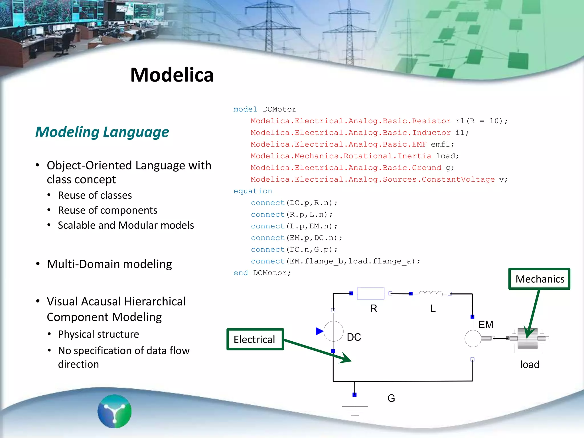
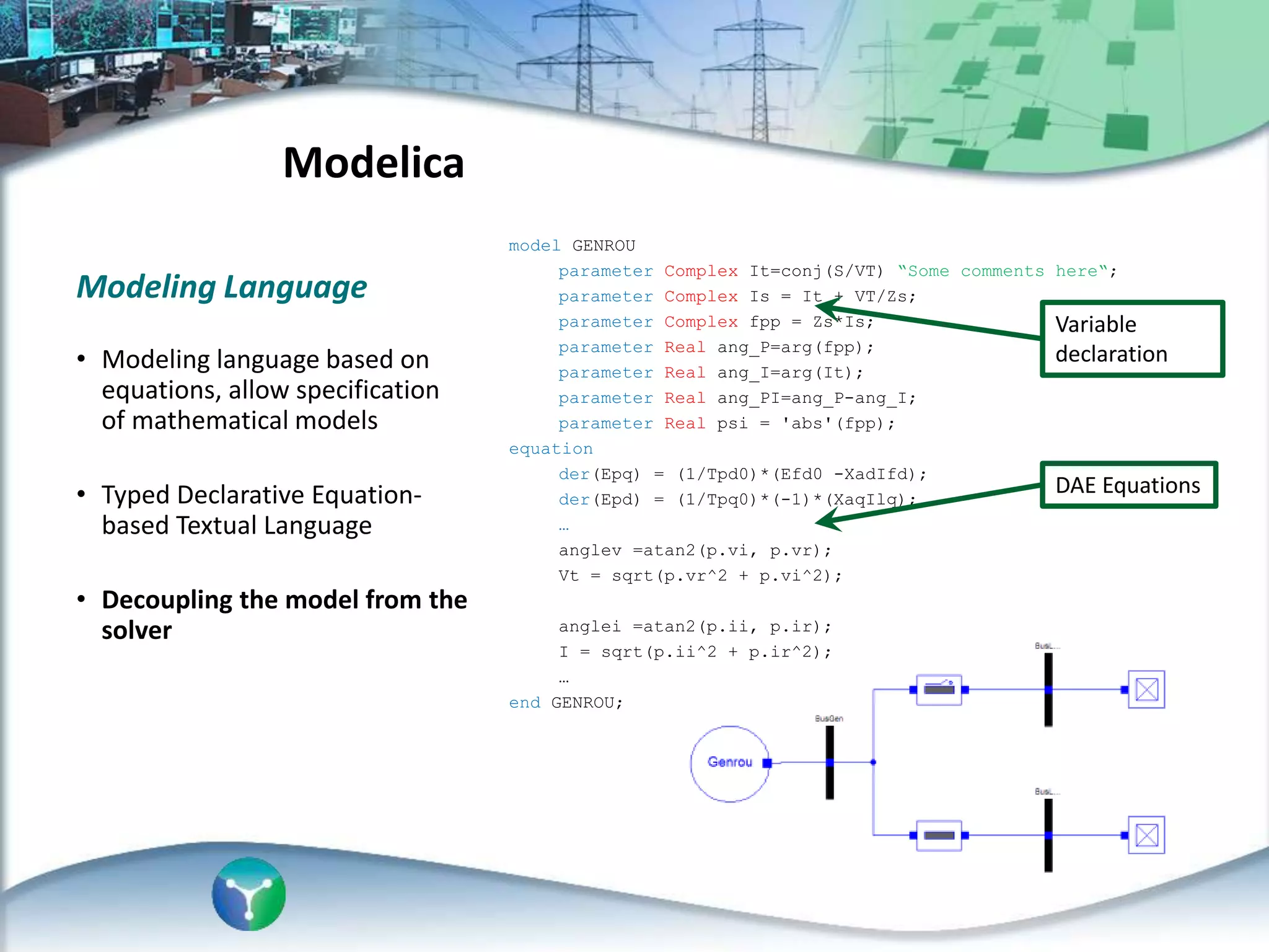
• Modelica is a non-proprietary, object-
oriented, equation based language to
conveniently model complex physical
systems
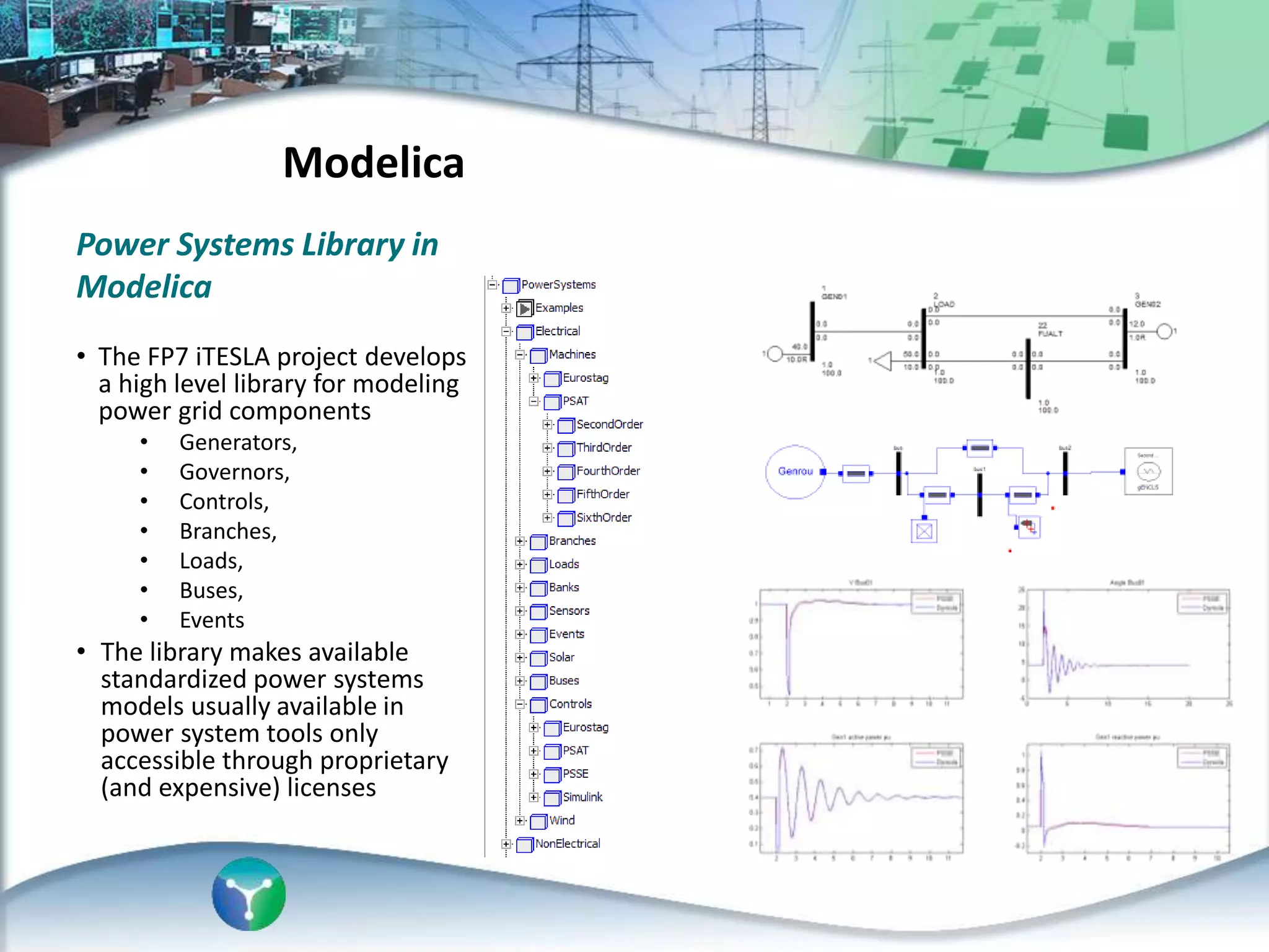
• Suitable modeling language for
standardization and exchange of
models
• Modelica tools, commercial and free of
charge
• Electric power steering and
controller model
[1] Andreas Deuring, Johannes
Gerl, Harald Wilhelm
“Multi-Domain Vehicle Dynamics
Simulation in Dymola”,
Modelica Conference, Dresden,
2011
• Thermodinamic Network
of the ICE model
[2] L. Morawietz, S. Risse, H.
Zellbeck, H. Reuss, T. Christ
“Modeling an automotive power
train and electrical power supply
for HiL applications using
Modelica”,
Modelica Conference, Hamburg,
2005
TU Dresden, University of
Stuttgart, BMW Group,
Germany.
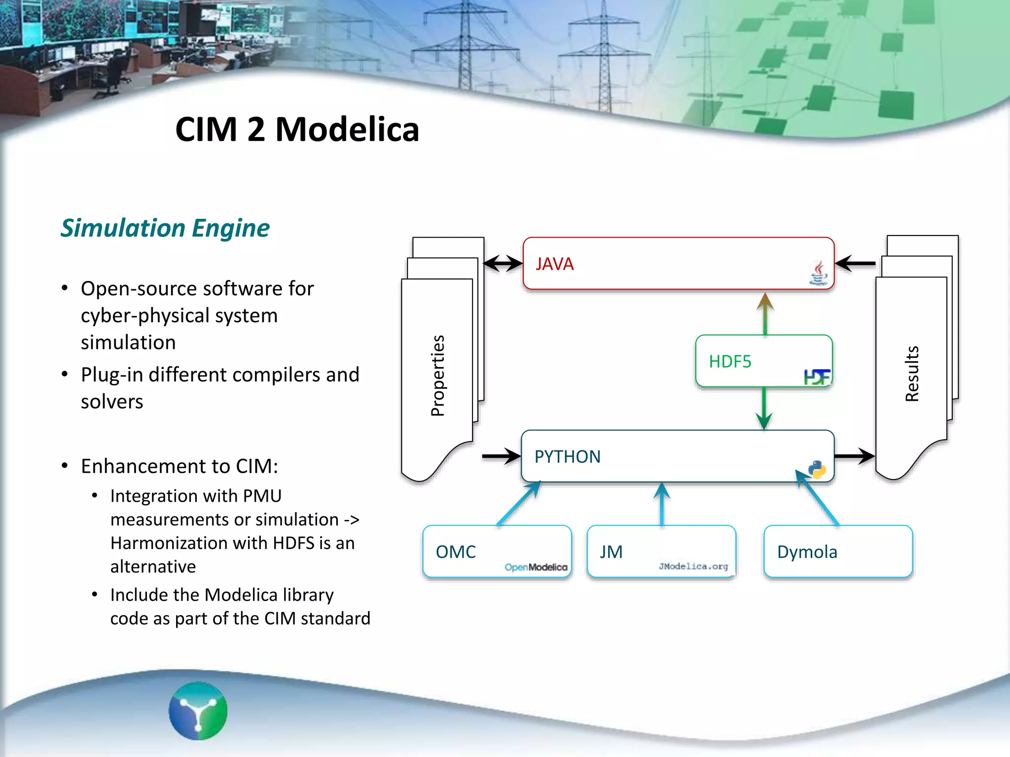
Background](https://image.slidesharecdn.com/gomezcim2modelica-140620060332-phpapp01/75/CIM-2-Modelica-4-2048.jpg)

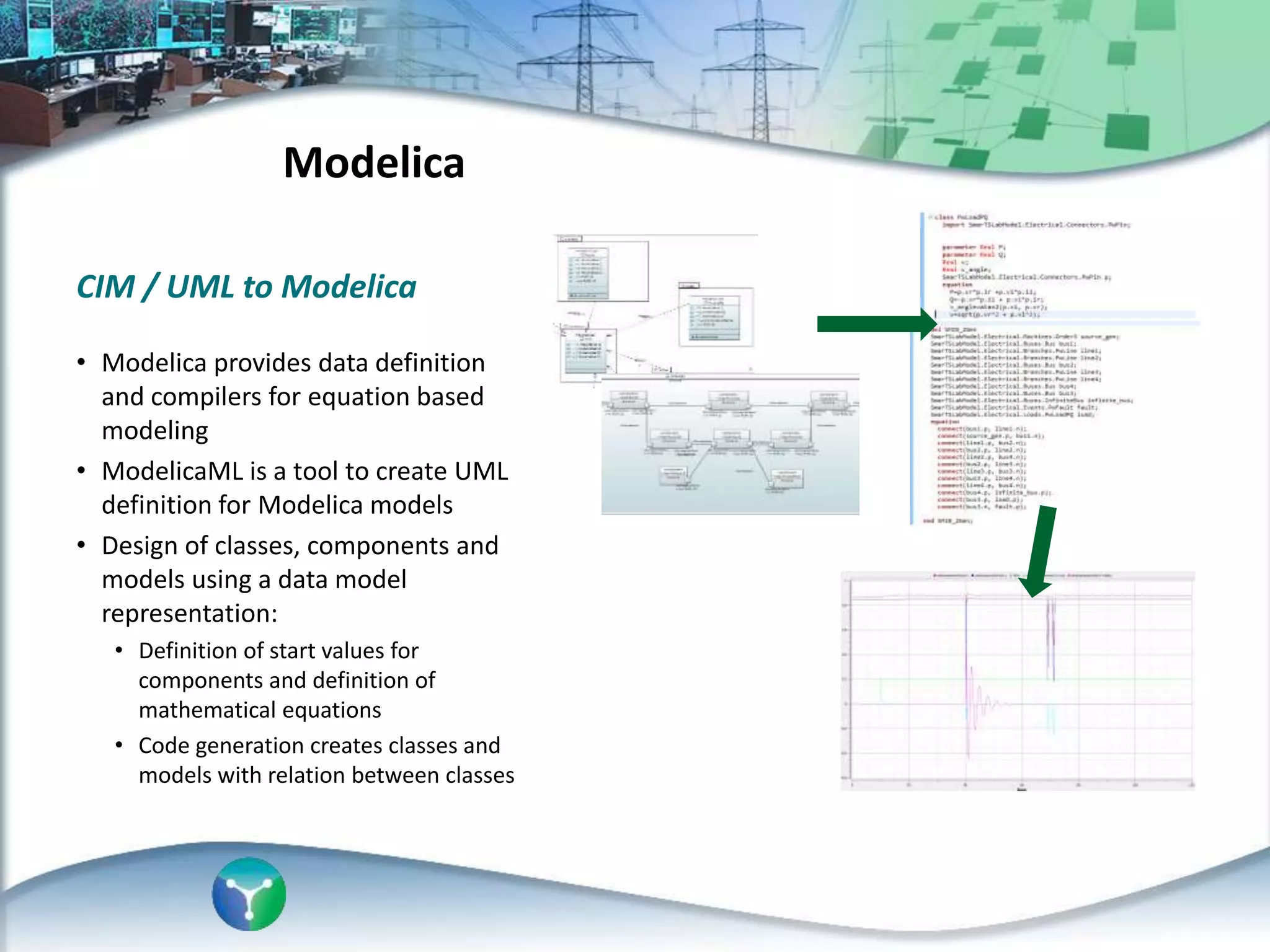
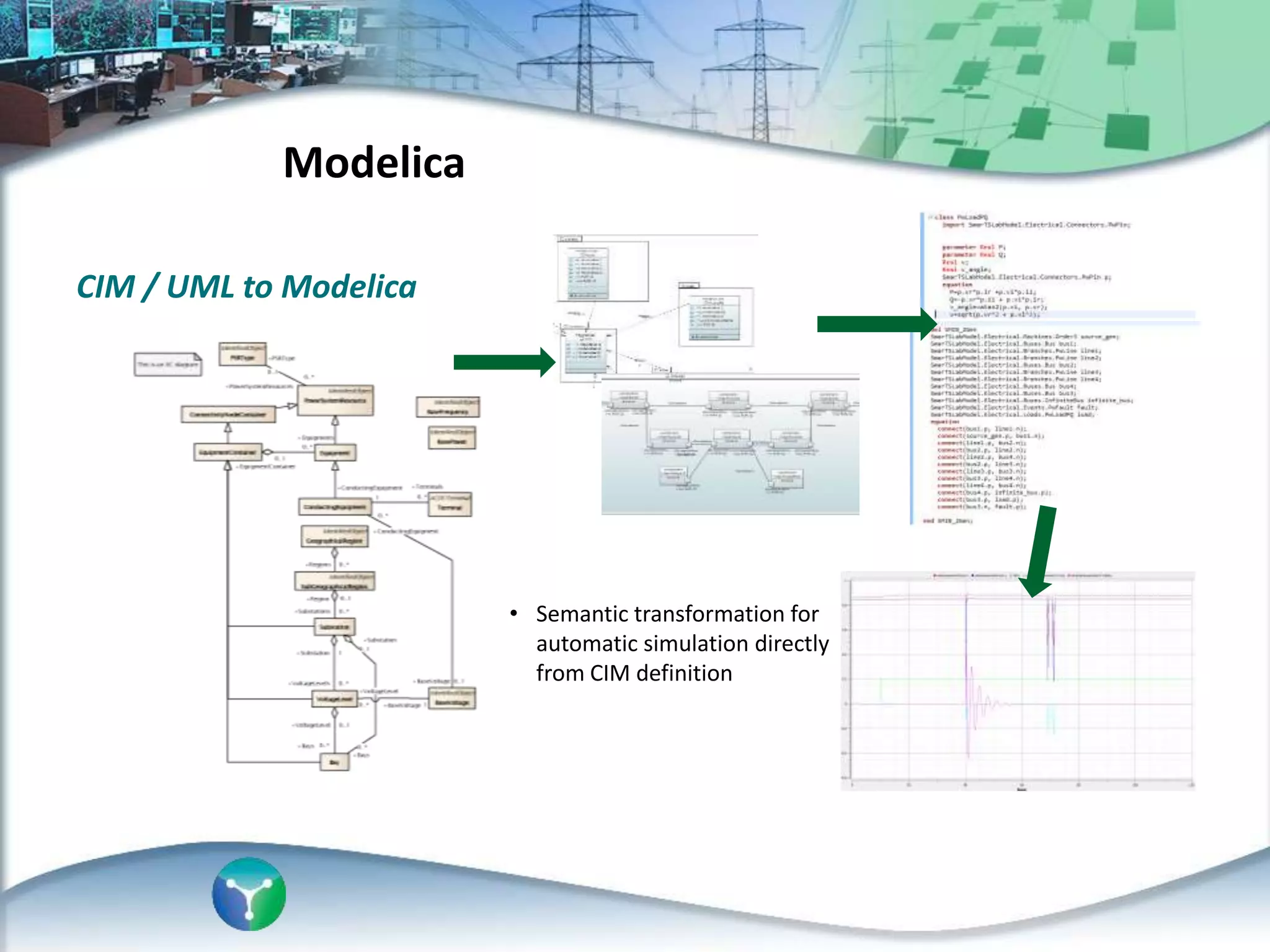
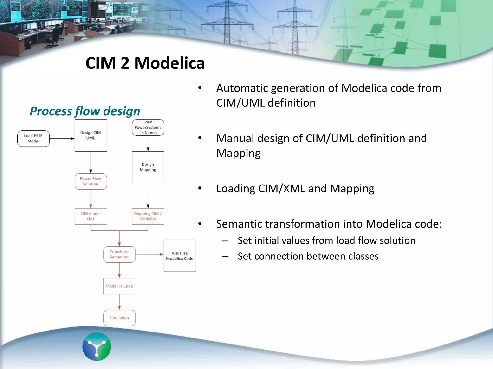

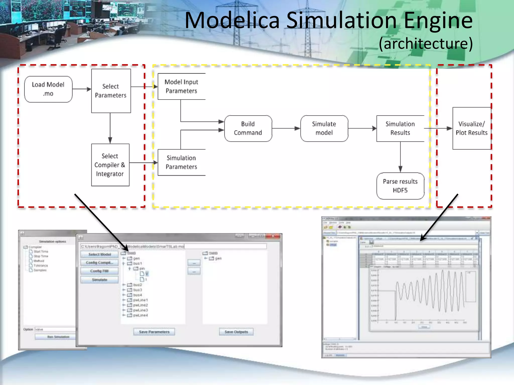

This document discusses an automated approach to generating Modelica models from CIM (Common Information Model) definitions for power system simulation. CIM provides a standard format for power system data, while Modelica is a modeling language suitable for complex physical systems. The proposed process involves semantically transforming CIM/UML definitions into Modelica code based on a defined mapping. This allows running time-domain simulations using standard power system models directly from utility data in CIM format. The resulting Modelica simulation engine could integrate real measurements to enable validation of generated models.