Download as PDF, PPTX


![72
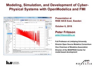
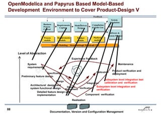
Optimization of Dynamic Trajectories Using
Multiple-Shooting and Collocation
• Minimize a goal function subject to model
equation constraints, useful e.g. for NMPC
• Multiple Shooting/Collocation
• Solve sub-problem in each sub-interval
0.0
2.0
4.0
6.0
8.0
10.0
12.0
14.0
16.0
1 2 4 8 16
MULTIPLE_COLLOCATION
ipopt [scaled] jac_g [scaled]
Example speedup, 16 cores:
In OpenModelica 1.9.1
beta release Jan 2014.](https://image.slidesharecdn.com/modelica-openmodelica-slides-240320173932-1e7f7616/85/Modelica-OpenModelica-slides-para-aprender-pdf-72-320.jpg)


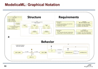
![78
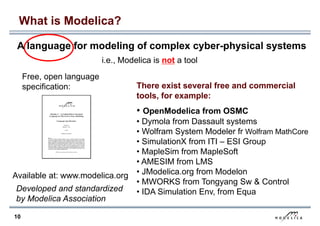
Need for Debugging Tools
Map Low vs High Abstraction Level
• A major part of the total cost of software projects
is due to testing and debugging
• US-Study 2002:
Software errors cost the US economy annually~ 60 Billion $
• Problem: Large Gap in Abstraction Level
from Equations to Executable Code
• Example error message (hard to understand)
Error solving nonlinear system 132
time = 0.002
residual[0] = 0.288956
x[0] = 1.105149
residual[1] = 17.000400
x[1] = 1.248448
...](https://image.slidesharecdn.com/modelica-openmodelica-slides-240320173932-1e7f7616/85/Modelica-OpenModelica-slides-para-aprender-pdf-78-320.jpg)


This document summarizes Peter Fritzson's presentation on modeling, simulation, and development of cyber-physical systems with OpenModelica and FMI. It discusses industrial challenges for complex cyber-physical systems and introduces OpenModelica as a free, open-source language and environment for modeling multi-domain systems. It provides examples of Modelica models for various applications like robotics, automotive, power plants, and more.


![Lect 1 Number systems and base conversions. [Autosaved].pptx](https://cdn.slidesharecdn.com/ss_thumbnails/lect1numbersystemsandbaseconversions-260111134109-67c2d865-thumbnail.jpg?width=640&height=640&fit=bounds)
