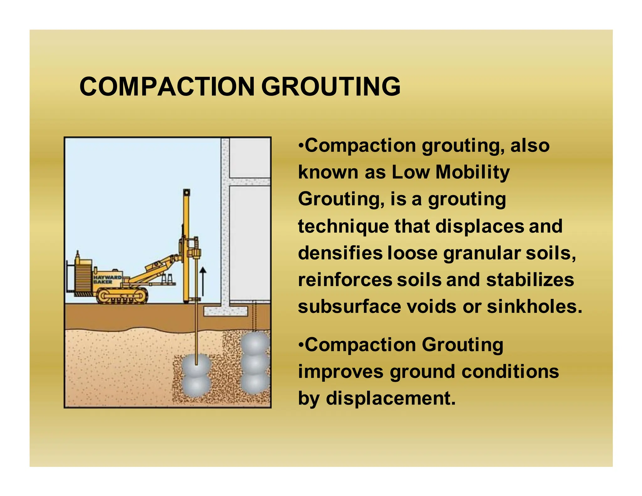
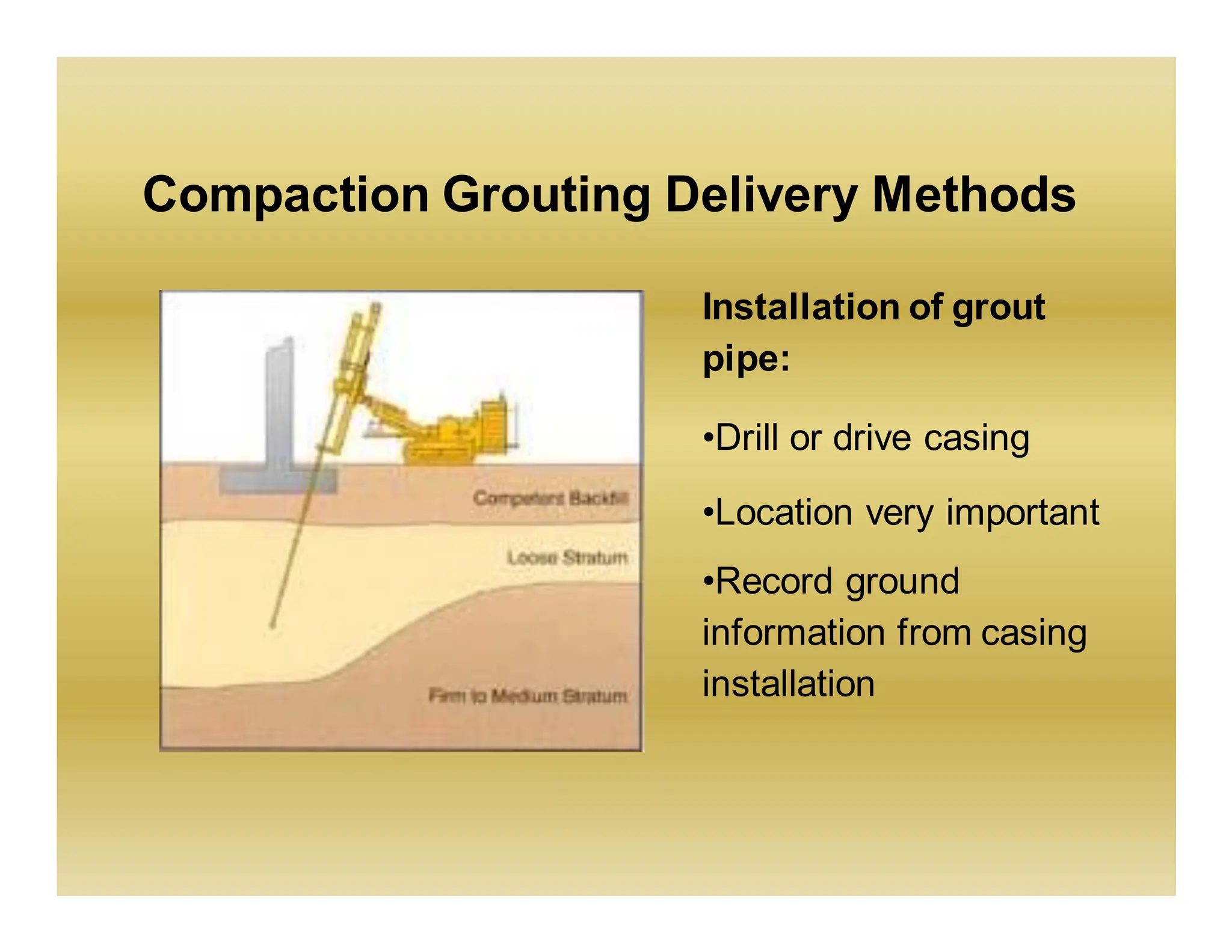
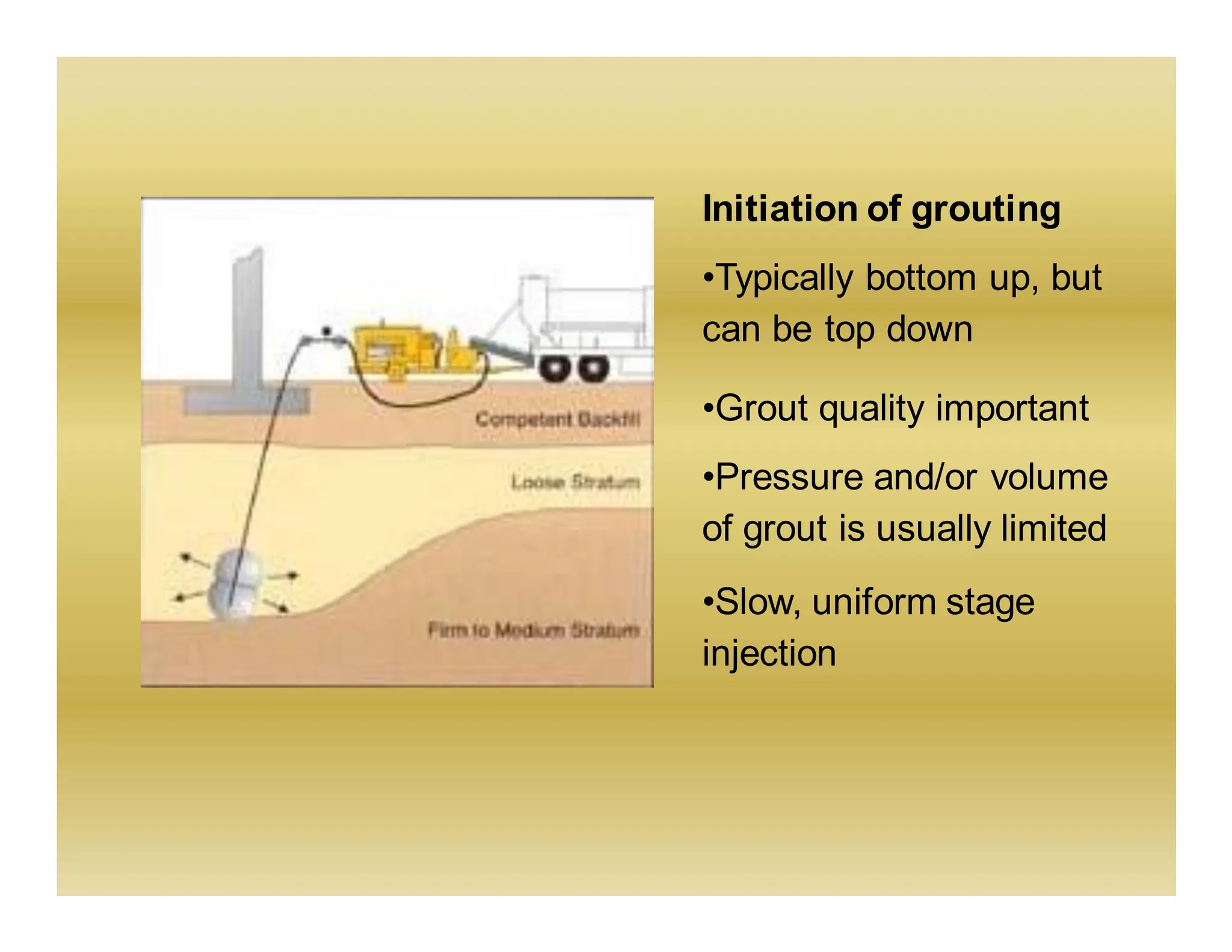
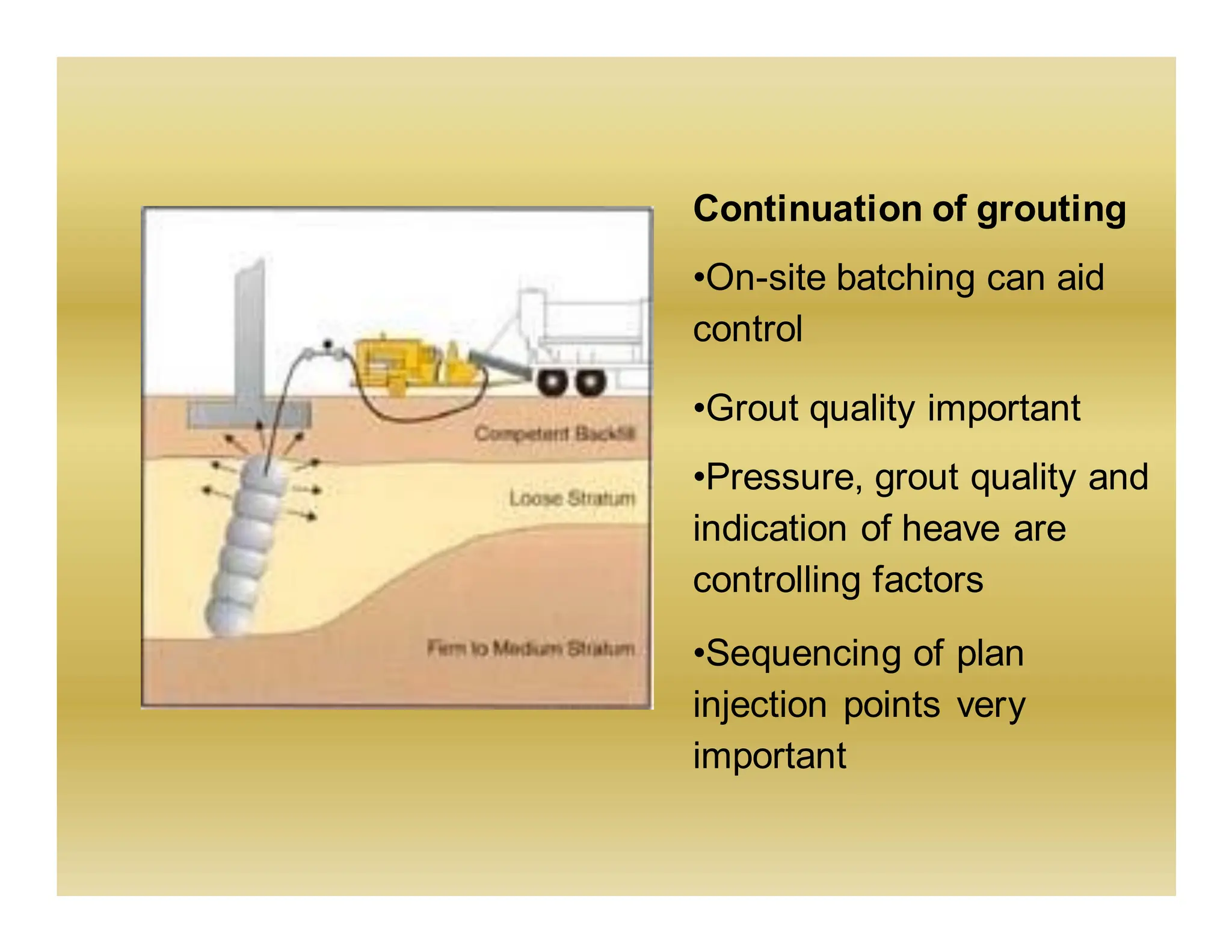
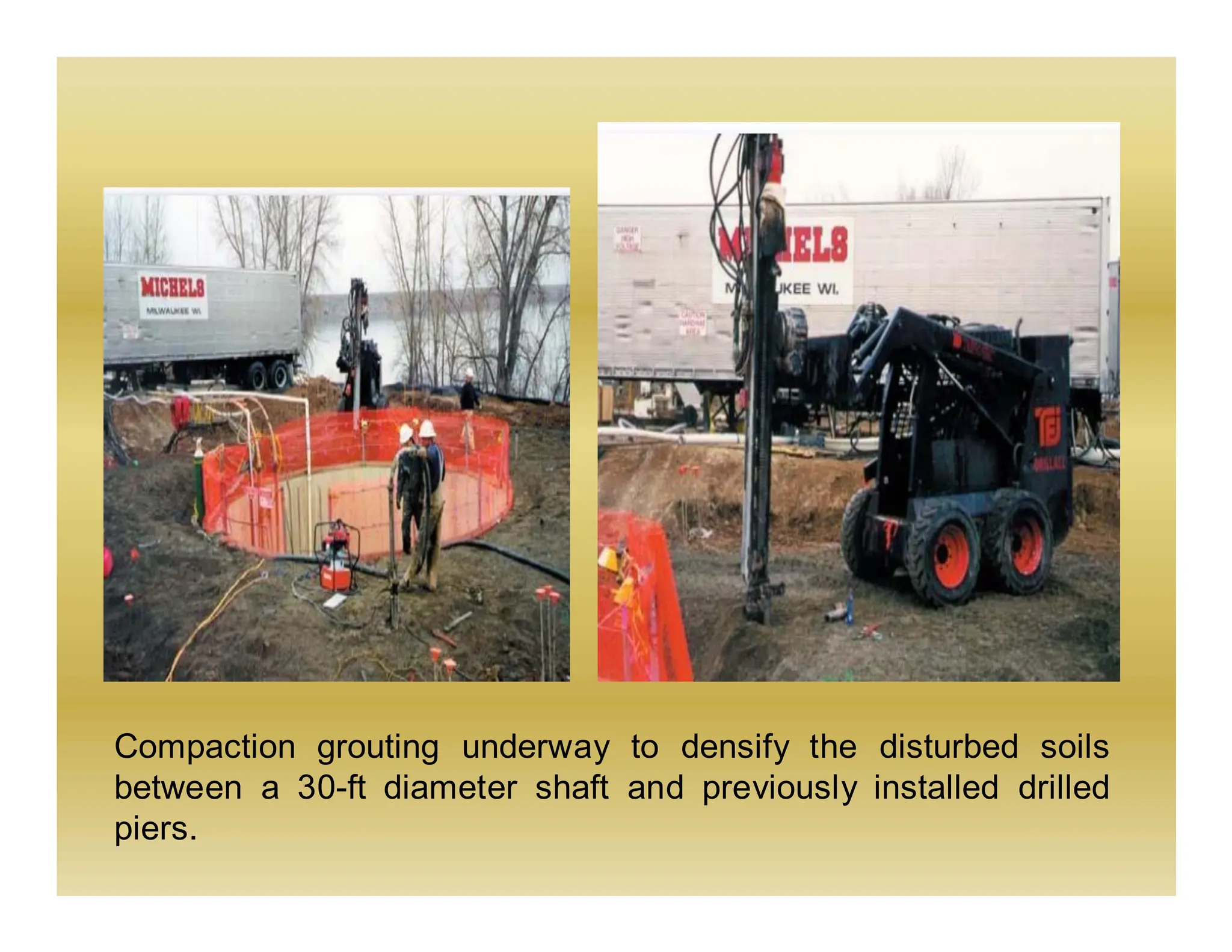
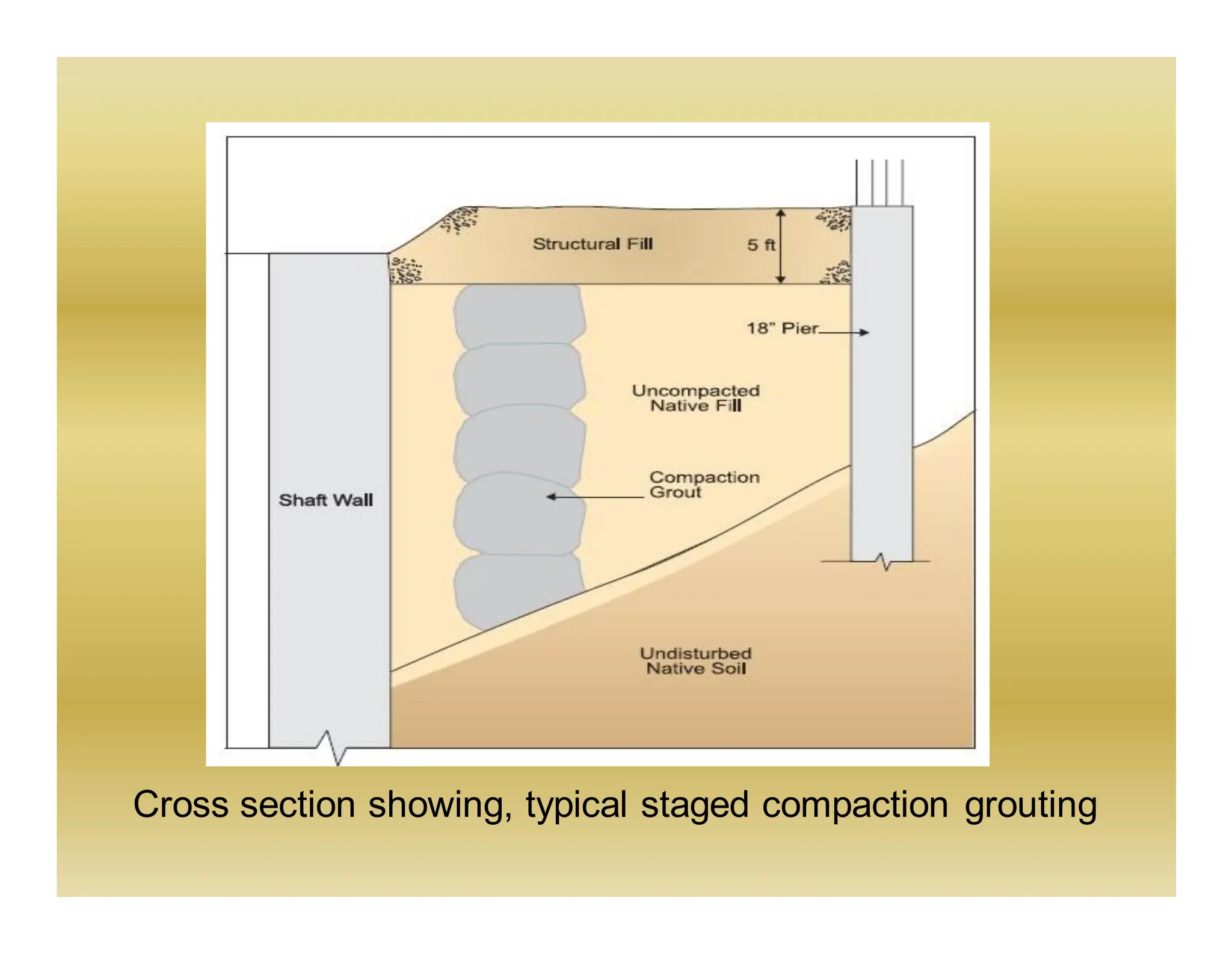
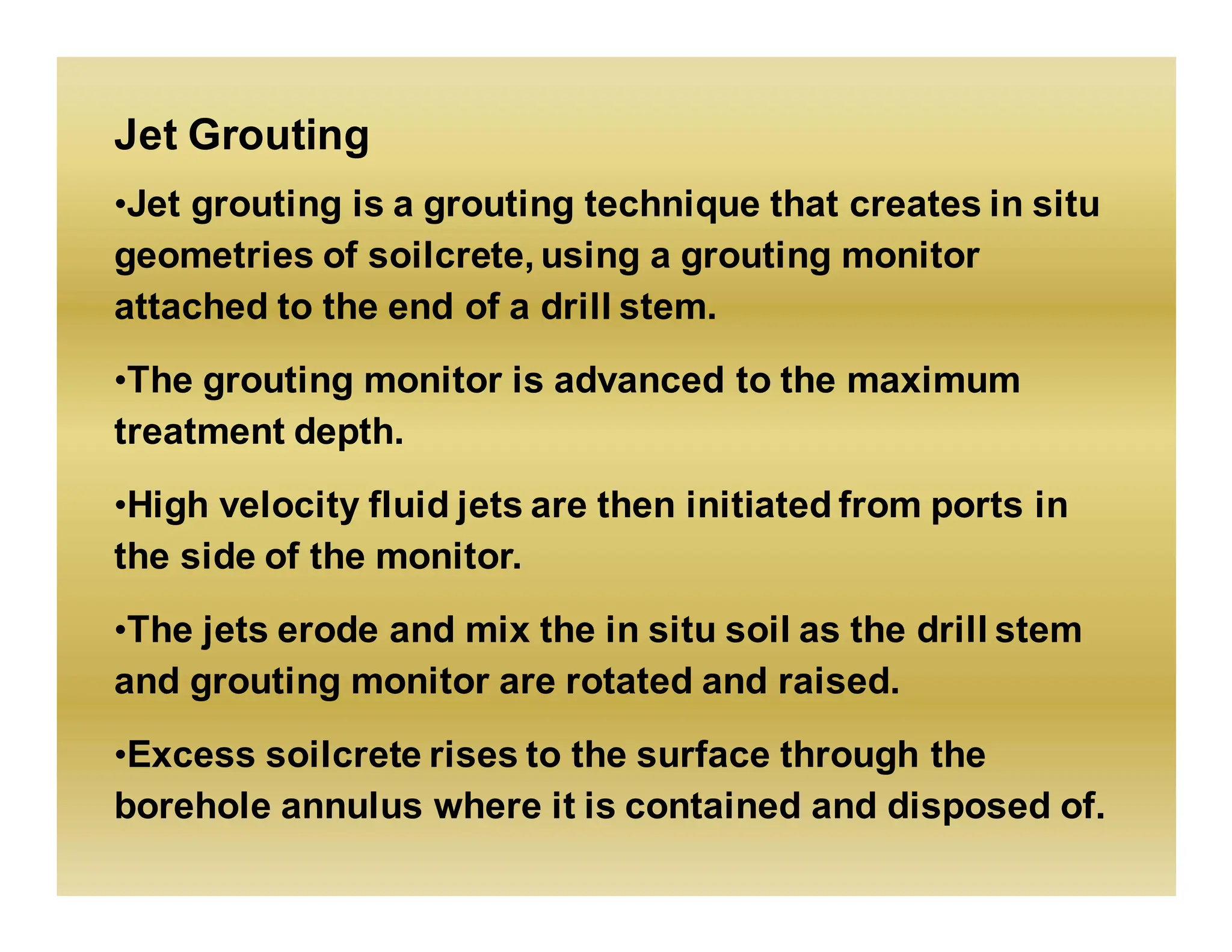
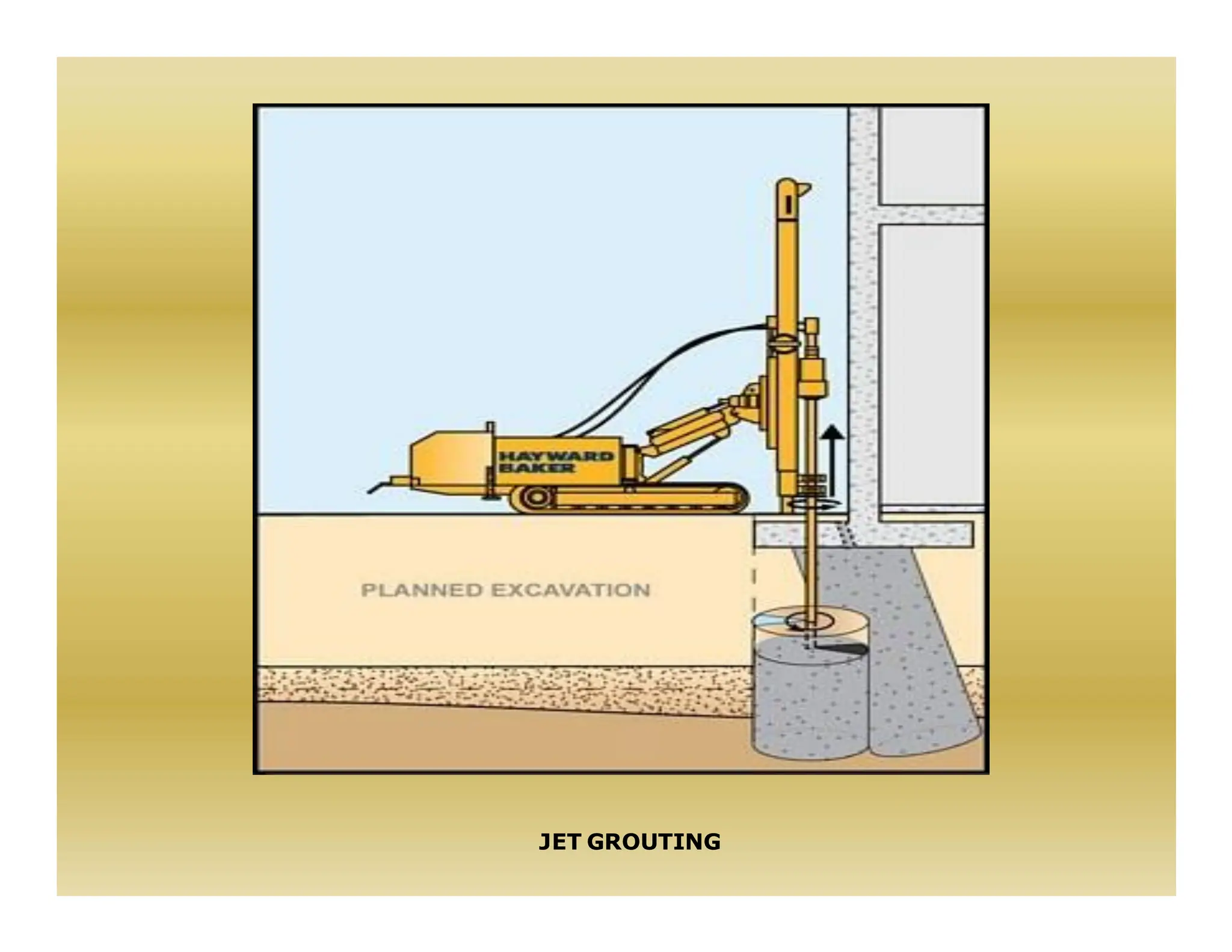
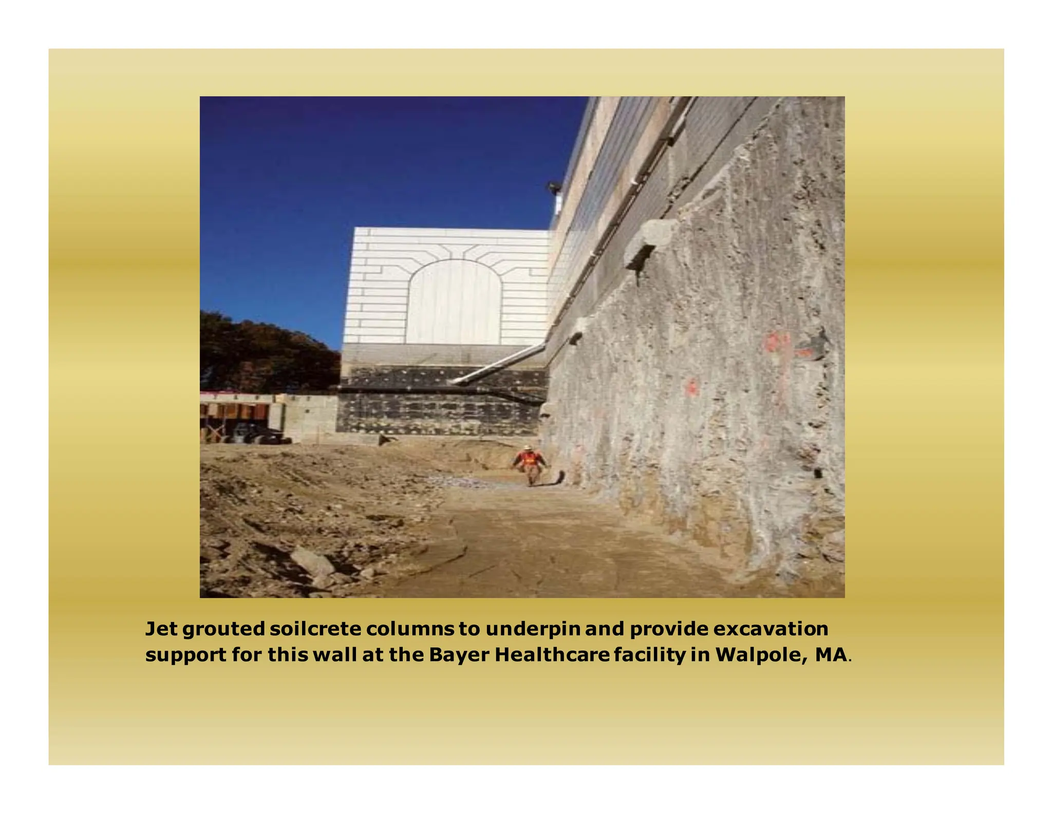
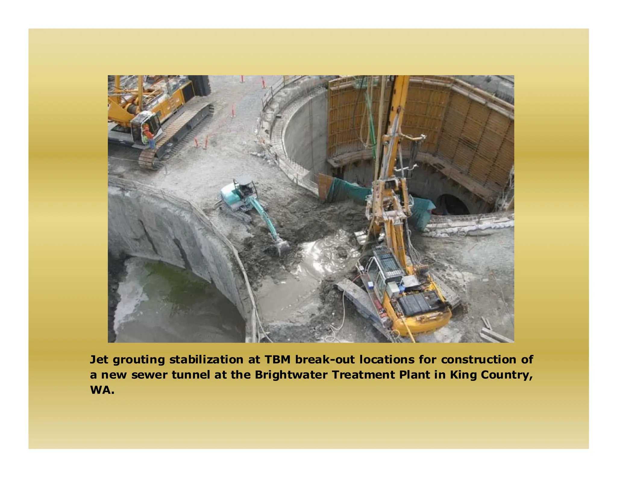
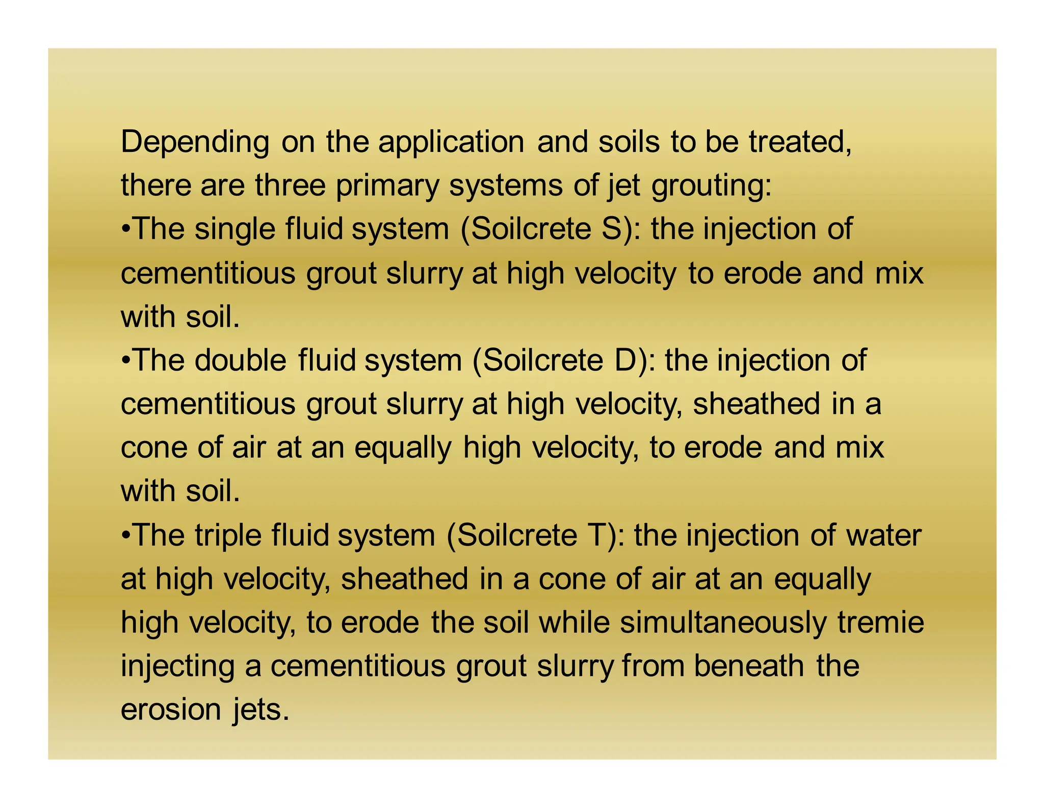
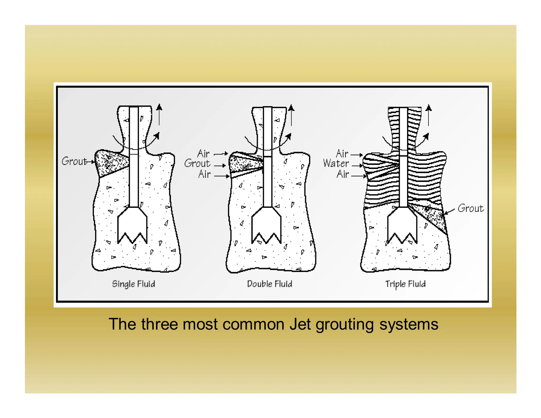
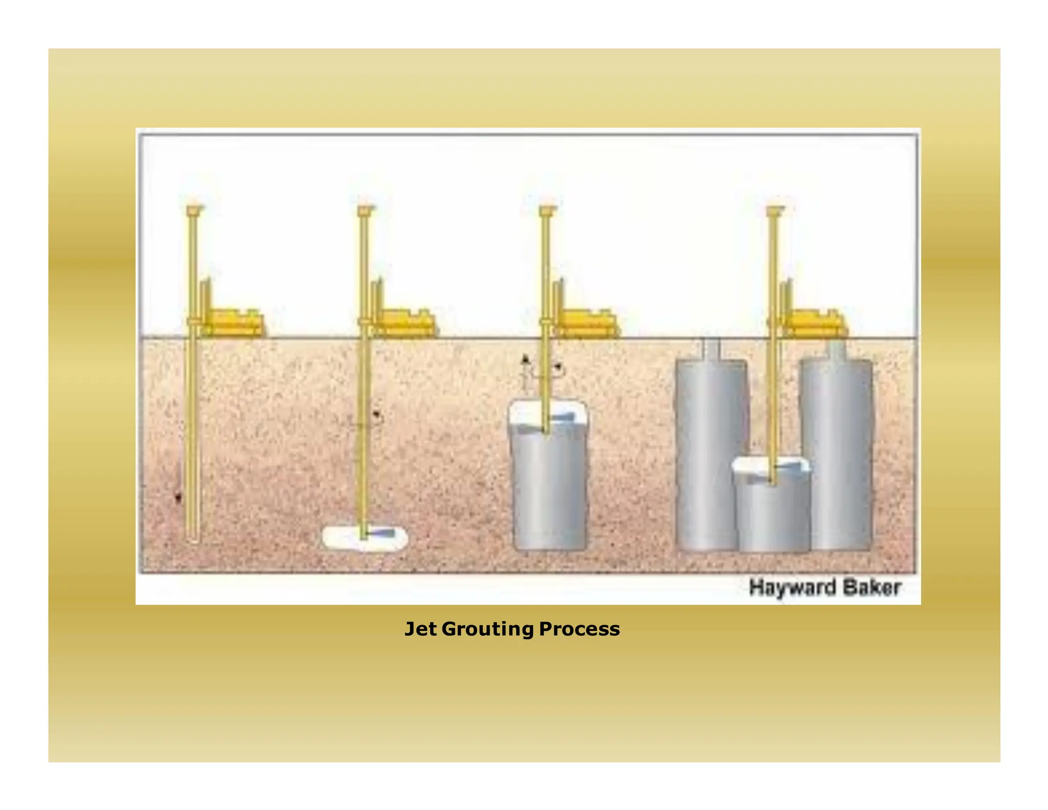
COMPACTION GROUTING
•Compaction grouting, also
known as Low Mobility
Grouting, is a grouting
technique that displaces and
densifies loose granular soils,
reinforces soils and stabilizes
subsurface voids or sinkholes.
•Compaction Grouting
improves ground conditions
by displacement.
Site Investigation
•Comprehensive knowledge of subsurface
conditions is important.
•A site investigation report generally contain site
geology and history, soil gradation and the in situ
horizontal permeability of each treatment stratum.
•Type and condition of nearby structure and utilities,
together with plan and elevation location, will further
assist program development.
Geotechnical Considerations
1. The in situ vertical stress in the treatment stratum
must be sufficient to enable the grout to displace
the soil horizontally.
2. The grout injection rate should be slow enough to
allow pore pressure dissipation.
3. Compaction grouting can usually be effective in
most silts and sands, provided that the soil is not
near saturation.
4. Soils that lose strength during remolding should be
avoided.
5. Greater displacement will occur in weaker soil
strata. Excavated grout bulbs confirm that
compaction grouting focuses improvement where it
is most needed.
6. Collapsible soils can usually be treated effectively
by adding water during drilling prior to compaction
grout injection.
7. Stratified soils, particularly thinly stratified soils,
can be cause for difficult or reduced improvement
capability.
Compaction Grouting Delivery Methods
Installation of grout
pipe:
•Drill or drive casing
•Location very important
•Record ground
information from casing
installation
Initiation of grouting
•Typically bottom up, but
can be top down
•Grout quality important
•Pressure and/or volume
of grout is usually limited
•Slow, uniform stage
injection
Continuation of grouting
•On-site batching can aid
control
•Grout quality important
•Pressure, grout quality and
indication of heave are
controlling factors
•Sequencing of plan
injection points very
important
Improvement Conditions
•Typically greater than 100 kPa overburden stress is required
to maximize densification.
•Limited densification can be achieved with less overburden.
•This stress can come from overburden soils, surcharge
loads and/or foundation loads.
•When densification is the primary intent, a replacement ratio
and pressure criterion is applied to each stage of compaction
grouting.
Replacement Ratio (RR) = CG Volume ~ 5 to 15%
Treatment Volume
•This ratio is determined based on the existing density, the
soil density range and the amount of displacement necessary
to affect the improvement.
•The maximum pressure criterion prevents fracture and
ground heave and compensates for stiff zones in the
treatment area.
•Vertical stages are usually set at 2- to 3-ft intervals; tighter
grid spacing will generally lead to better results.
Applications
Karstic Regions
•Pre-treatment for prevention of potential sinkholes is
common
•Pre-treatment usually involves drilling down to and into the
limestone surface to locate and fill any cavities, followed by
improvement of the loose soil above the rock surface.
Rubble Fill
•Construction debris and other similar fills are often placed in
an uncontrolled manner.
•To close the void spaces and minimize potential settlement
impact, compaction grouting is applied in a regular pattern.
Poorly Placed Fill
•Provided sufficient overburden stress exists, a proper
program of compaction grouting can treat the poorly
placed fill material.
Loosened Soil: Pre-Treatment
•Construction-generated ground disturbance can often be the
cause of soil loosening near the work area and can affect
nearby structure.
•The injection of compaction grout soon after the disturbance
occurs can compensate for the disturbance by re-establishing
the original stress state and prevent deformations beyond the
work area.
Liquefiable Soils
•Ground improvement consists of density increase, cellular
containment, and/or reinforcement.
•Sol permeability is an important parameter in determining the
rate of compaction grouting.
Collapsible Soils
•Collapsible soil conditions exist in specific regions where
wind-blown silts have accumulated or intermittent stream
flow deposition has occurred.
•Treatment of this soils is possible by forcing a restructuring
of the fine grains into a tighter configuration.
Advantages of Compaction Grouting
• pinpoint treatment
• Speed of installation
• Wide application range
• Effective in a variety of soil conditions
• Can be performed in very tight access and low
headroom conditions
• Non-hazardous
• No waste spoil disposal
• No need to connect to footing or column
•Non-destructive and adaptable to existing foundations
•Economic alternative to removal and replacement or
piling
•Able to reach depths unattainable by other methods
•Enhanced control and effectiveness of in situ treatment
with Denver System
Case study:
McClellan Pump Station Littleton, Colorado:
➢Construction of waste water lift station at the
McClellan pump station included the sinking of 40-ft
deep, 30-ft diameter shaft through uncompacted
native, silt sands.
➢The shaft was designed as a series of 10-ft deep
concrete ring sections installed from that top down,
with the bottom of the shaft reaching design elevation
at 40-ft below grade.
Compaction grouting underway to densify the disturbed soils
between a 30-ft diameter shaft and previously installed drilled
piers.
➢Some unanticipated problems were faced during the
construction process.
➢The problem due to side friction was overcome by
air and water jetting.
➢Additional fill was placed to restore the site to grade.
And the shaft was then completed.
Cross section showing, typical staged compaction grouting
Jet Grouting
•Jet grouting is a grouting technique that creates in situ
geometries of soilcrete, using a grouting monitor
attached to the end of a drill stem.
•The grouting monitor is advanced to the maximum
treatment depth.
•High velocity fluid jets are then initiated from ports in
the side of the monitor.
•The jets erode and mix the in situ soil as the drill stem
and grouting monitor are rotated and raised.
•Excess soilcrete rises to the surface through the
borehole annulus where it is contained and disposed of.
JET GROUTING
Jet grouted soilcrete columns to underpin and provide excavation
support for this wall at the Bayer Healthcare facility in Walpole, MA.
Jet grouting stabilization at TBM break-out locations for construction of
a new sewer tunnel at the Brightwater Treatment Plant in King Country,
WA.
Depending on the application and soils to be treated,
there are three primary systems of jet grouting:
•The single fluid system (Soilcrete S): the injection of
cementitious grout slurry at high velocity to erode and mix
with soil.
•The double fluid system (Soilcrete D): the injection of
cementitious grout slurry at high velocity, sheathed in a
cone of air at an equally high velocity, to erode and mix
with soil.
•The triple fluid system (Soilcrete T): the injection of water
at high velocity, sheathed in a cone of air at an equally
high velocity, to erode the soil while simultaneously tremie
injecting a cementitious grout slurry from beneath the
erosion jets.
The three most common Jet grouting systems
There are more variations of these systems than there are
systems themselves, but in most cases they are a
“bottom-up” process. That is to say, they use hydraulic
rotary drilling to reach the design depth, and at that point
initiate jet grouting parameters and procedure to create a
cementitious soil matrix commonly called soilcrete.
During grouting, the borehole annulus must be large
enough to permit unimpeded up-hole spoil return. this
allows for control of the in situ stress environment. A lack
of this spoil return will result in hydrofracturing the ground
and loss of control. Loss of this control can lead to
extreme inconsistencies in the soilcrete quality and
geometry.
Jet Grouting Process
Jet Grouting Procedure
Predrilling or foundation coring may be necessary
to access the treatment zone. Other emerging jet
grouting systems include SuperJet and X-Jet
grouting.
•SuperJet System: a double fluid system reliant
on specialized tooling and high injection energy
for enhanced erosion capability (up to 5m
diameter)
•X-Jet System: a triple fluid system using a pair
of colliding erosion jets to create a more uniform
and controlled diameter of treatment.
Concluding Remarks
Grouting is a versatile technique and has been proven to be
suitable to many ground improvement applications.
References
Hausmann M R (1984) Engineering principles of Ground
Modification.
Schafer et al (1997) Ground Improvement, Ground
Reinforcement, and Ground Treatment- Developments;
1987-1997, Geotechnical Special Publication; No 69.
Jian Chu (2009) Construction Processes, State of the Art
Report, ICSMGE, Alexandria, Egypt.

Git-Grouting. Civil engineering is shesar

  • 1.
    COMPACTION GROUTING •Compaction grouting,also known as Low Mobility Grouting, is a grouting technique that displaces and densifies loose granular soils, reinforces soils and stabilizes subsurface voids or sinkholes. •Compaction Grouting improves ground conditions by displacement.
  • 2.
    Site Investigation •Comprehensive knowledgeof subsurface conditions is important. •A site investigation report generally contain site geology and history, soil gradation and the in situ horizontal permeability of each treatment stratum. •Type and condition of nearby structure and utilities, together with plan and elevation location, will further assist program development.
  • 3.
    Geotechnical Considerations 1. Thein situ vertical stress in the treatment stratum must be sufficient to enable the grout to displace the soil horizontally. 2. The grout injection rate should be slow enough to allow pore pressure dissipation. 3. Compaction grouting can usually be effective in most silts and sands, provided that the soil is not near saturation. 4. Soils that lose strength during remolding should be avoided.
  • 4.
    5. Greater displacementwill occur in weaker soil strata. Excavated grout bulbs confirm that compaction grouting focuses improvement where it is most needed. 6. Collapsible soils can usually be treated effectively by adding water during drilling prior to compaction grout injection. 7. Stratified soils, particularly thinly stratified soils, can be cause for difficult or reduced improvement capability.
  • 5.
    Compaction Grouting DeliveryMethods Installation of grout pipe: •Drill or drive casing •Location very important •Record ground information from casing installation
  • 6.
    Initiation of grouting •Typicallybottom up, but can be top down •Grout quality important •Pressure and/or volume of grout is usually limited •Slow, uniform stage injection
  • 7.
    Continuation of grouting •On-sitebatching can aid control •Grout quality important •Pressure, grout quality and indication of heave are controlling factors •Sequencing of plan injection points very important
  • 8.
    Improvement Conditions •Typically greaterthan 100 kPa overburden stress is required to maximize densification. •Limited densification can be achieved with less overburden. •This stress can come from overburden soils, surcharge loads and/or foundation loads. •When densification is the primary intent, a replacement ratio and pressure criterion is applied to each stage of compaction grouting. Replacement Ratio (RR) = CG Volume ~ 5 to 15% Treatment Volume
  • 9.
    •This ratio isdetermined based on the existing density, the soil density range and the amount of displacement necessary to affect the improvement. •The maximum pressure criterion prevents fracture and ground heave and compensates for stiff zones in the treatment area. •Vertical stages are usually set at 2- to 3-ft intervals; tighter grid spacing will generally lead to better results.
  • 10.
    Applications Karstic Regions •Pre-treatment forprevention of potential sinkholes is common •Pre-treatment usually involves drilling down to and into the limestone surface to locate and fill any cavities, followed by improvement of the loose soil above the rock surface.
  • 11.
    Rubble Fill •Construction debrisand other similar fills are often placed in an uncontrolled manner. •To close the void spaces and minimize potential settlement impact, compaction grouting is applied in a regular pattern. Poorly Placed Fill •Provided sufficient overburden stress exists, a proper program of compaction grouting can treat the poorly placed fill material.
  • 12.
    Loosened Soil: Pre-Treatment •Construction-generatedground disturbance can often be the cause of soil loosening near the work area and can affect nearby structure. •The injection of compaction grout soon after the disturbance occurs can compensate for the disturbance by re-establishing the original stress state and prevent deformations beyond the work area.
  • 13.
    Liquefiable Soils •Ground improvementconsists of density increase, cellular containment, and/or reinforcement. •Sol permeability is an important parameter in determining the rate of compaction grouting. Collapsible Soils •Collapsible soil conditions exist in specific regions where wind-blown silts have accumulated or intermittent stream flow deposition has occurred. •Treatment of this soils is possible by forcing a restructuring of the fine grains into a tighter configuration.
  • 14.
    Advantages of CompactionGrouting • pinpoint treatment • Speed of installation • Wide application range • Effective in a variety of soil conditions • Can be performed in very tight access and low headroom conditions • Non-hazardous • No waste spoil disposal • No need to connect to footing or column
  • 15.
    •Non-destructive and adaptableto existing foundations •Economic alternative to removal and replacement or piling •Able to reach depths unattainable by other methods •Enhanced control and effectiveness of in situ treatment with Denver System
  • 16.
    Case study: McClellan PumpStation Littleton, Colorado: ➢Construction of waste water lift station at the McClellan pump station included the sinking of 40-ft deep, 30-ft diameter shaft through uncompacted native, silt sands. ➢The shaft was designed as a series of 10-ft deep concrete ring sections installed from that top down, with the bottom of the shaft reaching design elevation at 40-ft below grade.
  • 17.
    Compaction grouting underwayto densify the disturbed soils between a 30-ft diameter shaft and previously installed drilled piers.
  • 18.
    ➢Some unanticipated problemswere faced during the construction process. ➢The problem due to side friction was overcome by air and water jetting. ➢Additional fill was placed to restore the site to grade. And the shaft was then completed.
  • 19.
    Cross section showing,typical staged compaction grouting
  • 20.
    Jet Grouting •Jet groutingis a grouting technique that creates in situ geometries of soilcrete, using a grouting monitor attached to the end of a drill stem. •The grouting monitor is advanced to the maximum treatment depth. •High velocity fluid jets are then initiated from ports in the side of the monitor. •The jets erode and mix the in situ soil as the drill stem and grouting monitor are rotated and raised. •Excess soilcrete rises to the surface through the borehole annulus where it is contained and disposed of.
  • 21.
  • 22.
    Jet grouted soilcretecolumns to underpin and provide excavation support for this wall at the Bayer Healthcare facility in Walpole, MA.
  • 23.
    Jet grouting stabilizationat TBM break-out locations for construction of a new sewer tunnel at the Brightwater Treatment Plant in King Country, WA.
  • 24.
    Depending on theapplication and soils to be treated, there are three primary systems of jet grouting: •The single fluid system (Soilcrete S): the injection of cementitious grout slurry at high velocity to erode and mix with soil. •The double fluid system (Soilcrete D): the injection of cementitious grout slurry at high velocity, sheathed in a cone of air at an equally high velocity, to erode and mix with soil. •The triple fluid system (Soilcrete T): the injection of water at high velocity, sheathed in a cone of air at an equally high velocity, to erode the soil while simultaneously tremie injecting a cementitious grout slurry from beneath the erosion jets.
  • 25.
    The three mostcommon Jet grouting systems
  • 26.
    There are morevariations of these systems than there are systems themselves, but in most cases they are a “bottom-up” process. That is to say, they use hydraulic rotary drilling to reach the design depth, and at that point initiate jet grouting parameters and procedure to create a cementitious soil matrix commonly called soilcrete. During grouting, the borehole annulus must be large enough to permit unimpeded up-hole spoil return. this allows for control of the in situ stress environment. A lack of this spoil return will result in hydrofracturing the ground and loss of control. Loss of this control can lead to extreme inconsistencies in the soilcrete quality and geometry.
  • 27.
  • 28.
    Jet Grouting Procedure Predrillingor foundation coring may be necessary to access the treatment zone. Other emerging jet grouting systems include SuperJet and X-Jet grouting. •SuperJet System: a double fluid system reliant on specialized tooling and high injection energy for enhanced erosion capability (up to 5m diameter) •X-Jet System: a triple fluid system using a pair of colliding erosion jets to create a more uniform and controlled diameter of treatment.
  • 29.
    Concluding Remarks Grouting isa versatile technique and has been proven to be suitable to many ground improvement applications.
  • 30.
    References Hausmann M R(1984) Engineering principles of Ground Modification. Schafer et al (1997) Ground Improvement, Ground Reinforcement, and Ground Treatment- Developments; 1987-1997, Geotechnical Special Publication; No 69. Jian Chu (2009) Construction Processes, State of the Art Report, ICSMGE, Alexandria, Egypt.