
More Related Content
What's hot
What's hot (20)
Viewers also liked
Viewers also liked (15)
Similar to gibbscam-mlr166-programming-macros-automate-cams-reach
Similar to gibbscam-mlr166-programming-macros-automate-cams-reach (20)
gibbscam-mlr166-programming-macros-automate-cams-reach
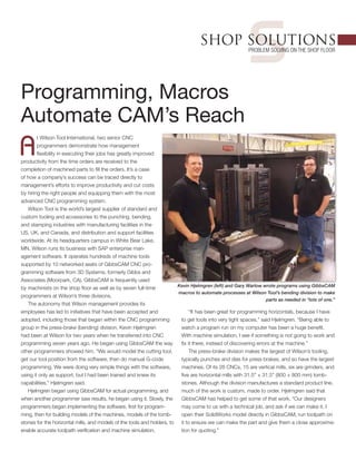
- 1. sSHOP SOLUTIONS Problem Solving on the Shop Floor Programming, Macros Automate CAM’s Reach A t Wilson Tool International, two senior CNC programmers demonstrate how management flexibility in executing their jobs has greatly improved productivity from the time orders are received to the completion of machined parts to fill the orders. It’s a case of how a company’s success can be traced directly to management’s efforts to improve productivity and cut costs by hiring the right people and equipping them with the most advanced CNC programming system. Wilson Tool is the world’s largest supplier of standard and custom tooling and accessories to the punching, bending, and stamping industries with manufacturing facilities in the US, UK, and Canada, and distribution and support facilities worldwide. At its headquarters campus in White Bear Lake, MN, Wilson runs its business with SAP enterprise man- agement software. It operates hundreds of machine tools supported by 10 networked seats of GibbsCAM CNC pro- gramming software from 3D Systems, formerly Gibbs and Associates (Moorpark, CA). GibbsCAM is frequently used by machinists on the shop floor as well as by seven full-time programmers at Wilson’s three divisions. The autonomy that Wilson management provides its employees has led to initiatives that have been accepted and adopted, including those that began within the CNC programming group in the press-brake (bending) division. Kevin Hjelmgren had been at Wilson for two years when he transferred into CNC programming seven years ago. He began using GibbsCAM the way other programmers showed him. “We would model the cutting tool, get our tool position from the software, then do manual G-code programming. We were doing very simple things with the software, using it only as support, but I had been trained and knew its capabilities,” Hjelmgren said. Hjelmgren began using GibbsCAM for actual programming, and when another programmer saw results, he began using it. Slowly, the programmers began implementing the software, first for program- ming, then for building models of the machines, models of the tomb- stones for the horizontal mills, and models of the tools and holders, to enable accurate toolpath verification and machine simulation. “It has been great for programming horizontals, because I have to get tools into very tight spaces,” said Hjelmgren. “Being able to watch a program run on my computer has been a huge benefit. With machine simulation, I see if something is not going to work and fix it there, instead of discovering errors at the machine.” The press-brake division makes the largest of Wilson’s tooling, typically punches and dies for press brakes, and so have the largest machines. Of its 26 CNCs, 15 are vertical mills, six are grinders, and five are horizontal mills with 31.5" × 31.5" (800 × 800 mm) tomb- stones. Although the division manufactures a standard product line, much of the work is custom, made to order. Hjelmgren said that GibbsCAM has helped to get some of that work. “Our designers may come to us with a technical job, and ask if we can make it. I open their SolidWorks model directly in GibbsCAM, run toolpath on it to ensure we can make the part and give them a close approxima- tion for quoting.” Kevin Hjelmgren (left) and Gary Warlow wrote programs using GibbsCAM macros to automate processes at Wilson Tool’s bending division to make parts as needed in “lots of one.”
- 2. A feature of the software that programmers rely on is saving machining processes for reuse. A process incorporates the type of feature to be machined, tools used, machining style—all the variables a programmer would need to specify. Later, the programmer can recall the process and use it as is or, if there is an ECO, change the affected variable. The program is automatically regenerated. “This has saved us a lot of time and it has helped with changes we are making in our work flow, for which I’m reprogramming around 200 parts.” Until last year, the work flow using the horizontal mills was batch processing—making lots of 30–50 parts and keeping an inventory. Scheduling mills for custom jobs, which arrive daily, was a challenge. Furthermore, because of the scheduling system, programming requires specifying the tombstone and angle of rotation (tombstone face)—B0, B90, B180 or B270—for machining. However, programmers can’t predict which tombstone or face will be open next. To tackle the problem, the press-brake group decided to move from batch processing to “lots of one,” making parts as needed, which was enabled, in part, by the work of another programmer. Gary Warlow, with 22 years’ experience at Wilson Tool in England, transferred to Minnesota in 2011, and began using GibbsCAM two years ago. He learned it quickly, in part because it is easy to use and processes are easy to set up. Then he began writing GibbsCAM macros, application program interfaces that use a specific language provided to GibbsCAM users. 3D Systems (formerly Gibbs and Associates) writes the code that automates GibbsCAM functions, and maintains a user wiki with the macro commands to use the functions, but macros use a specific syntax or sequence, and become complex in multiaxis programming. Warlow has years of experience in writing macros for other applications and has even written macros to automatically model parts with SolidWorks. He learned to use the GibbsCAM language to automatically program many repetitive tasks, including selecting and sizing geometry, specifying tools, and running processes. Management recognized what he was doing, and initiated a roll-out of automation based on his macros. Moving to “lots of one” is one of the projects. Warlow writes dynamic GibbsCAM macros that call up and incorporate the appropriate part programs generated by Hjelmgren, but the initial rotation angle is output as a variable, letting a machine operator run the program on any tombstone face. GibbsCAM generates a setup sheet to inform operators of the program number, setup, tools, machining operations, and run time. When the program gets to the variable, it calls subroutines and waits for the operator to enter tombstone and face identifiers. All operations are loaded as a G55 (initial coordinate system), but the macro outputs a G56 (new coordinate system) at every rotation, dynamically updating location. Another project initiated through Warlow’s macros goes much farther, and incorporates data generated by the SAP system. When an order is entered, data about the parts are collected. The SAP system can generate a flat file or data file with coded infor- mation about geometry and dimensions. The system is set up to generate a bar code with the job order. The press-brake group integrated bar-code readers with GibbsCAM workstations, and Warlow wrote macros that read the part number from the bar code, open GibbsCAM, and model the part. The macros run in the back- ground, doing mathematical and trigonometric manipulation on the SAP flat file data, to generate values that populate the required variables. It then calls the appropriate saved tools and machining processes, machines the part, generates the part program, post processes the file, and outputs a setup sheet. “It takes about 30 seconds for all this to happen,” Warlow said, “That’s faster than opening a SolidWorks file.” The press-brake division selected 26 product families for the initial automation project. “Every dimension is available for those product families within the SAP data, and we completed the project in February,” said Warlow. “Now, our ongoing project is to automate the rest of the families. Not all products have a flat file, but we’re working on that, so for these parts I have macros stop with drop- down menus, and I enter the data off a print.” With the progress made, Gary Warlow expects automation projects to go division-wide at all press-brake locations. He is now training two programmers on macro development, one in his own division, for backup, and one in the punching division. “I’ve been meeting with the punching group, and they want to change their manufacturing process, develop what we’ve done, and even go further,” Warlow said. “The GibbsCAM macros are fantastic. It’s unbelievable what you can do with them. I don’t know everything, but I’ve gone a long way with them.” For more information from 3D Systems, formerly Gibbs and Associates, go to www.gibbscam.com, or phone 805-523-0004. SHOP SOLUTIONS ENGINEERING MAY 2015 Copyright Notice: 2015 Copyright by Society of Manufacturing Engineers. All rights retained. This article appears with permission from Manufacturing Engineering, the official publication of SME. “With machine simulation, I see if something is not going to work and fix it there, instead of discovering errors at the machine.” MLR166/PDF/0515