(SHREYA) Chakan Call Girls Just Call 7001035870 [ Cash on Delivery ] Pune Esc...
Gck lv switchgear pt
1. LV withdrawable switchgear cabinet
!"#$%&'#$()
GCK(L)
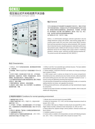
GCK(L) !"#$%&'#$()*+,-. 50Hz !"#
380V !"#$% !"#$(PC) !"#$%(MCC)
!"#$%&'()*+ !"#$ !" !
!"# !" !"#$% !
!"#$%&'()*+,&-./
!" IEC-439 GB7251.1
GCK(L) LV withdrawable switchgear cabinetis applicable to the low
voltage distribution system with AC50Hz, rated working voltage 380V. It
contains power center (PC) and motor control center (MCC) functions.
Each technical parameter all reaches national standards. With character-
istics of advanced structure, beautiful appearance, high electric performance,
high protection grade, reliable and safe and easy to maintain. It is the ideal
distribution device for low voltage power supply system in metallurgy,
petroleum, chemical, power, machinery and light weaving industries etc.
The product accords with standards IEC-439, GB7251.1.
1. GCK(L)1 and GCJ1 are assemble type combined structure. The basic skeleton
is assembled by adopting special bar steel.
2. Cabinet skeleton, component dimension and starter size change according to
basic modulus E=25mm.
3. In MCC project, parts in cabinet are divided into five zones (compartment):
horizontal bus bar zone, vertical bus bar zone, function unit zone, cable compartment,
and neutral earthing bus bar zone. Each zone is separated mutually for circuit s
normal running and effectively preventing fault expansion.
4. As all structures of framework are connected and firmed by bolts, so it avoids the
welding distortion and stress, and upgrades the precision.
5. Strong general performance, well applicability and high standardization degree
for components.
6. Draw-out and insert of function unit (drawer) is lever operation, which is easy and
reliable with rolling bearing.
1. Altitude above sea level should not exceed 2000M.
2. Ambient air temperature: -5 ~+40 and the average temperature should not
exceed +35 in 24h.
3. Air condition: With clean air. Relative humidity should not exceed 50% at +40 .
Higher relative humidity is allowed at lower temperature. Ex. 90% at +20 .
4. Places without fire, explosive danger, serious pollution, chemical corrosion and
fierce vibration.
5. Installation gradient not exceed 5 .
6. Control center is suitable to the transportation and store with following tempera-
ture :-25 ~+55 , in short time (within 24h) it should not exceed +70 .
!"#$% Conditions for normal operating environment
General
Characteristics
1. GCK(L)1 GCJ1 !"#$%& !"#$#%
!"
2. !" !"#$% !&'()* E=25mm
3. MCC ! !"#$%& !"#
!"# !"# ! !"#$%
! !"#$%& !"#$%&
4. !"#$%&'()*+,-./01 !"#
!" !"#
5. !"#$% !" !"#$
6. ! ! ! !"#$% !"#
!"#$
1. !"#$ 2000
2. !"#$%&+40 -5 24h
!" +35
3. ! !" !"#!$ +40 !"
50% !"#$%&!'()*+ , +20
90%
4. !" !" !" !"#$%&'()*
5. !"#$%& 5
6. !"#$%&'()*+,-./ -25 ~+55
!"( 24h) +70
2. PC PC cabinet
MCC MCC cabinet
! Height of drawer
! Power receiving or feeding
!" Power receiving or bus bar connection
!" Power receiving or bus bar connection
!"#$%&'( H 1600 ! "#$% 1840
Note: H of combined function unit of outlet cabinet is 1600. If not using public power, it will achieve 1840.
2200 600(800 1000) 1000
2200 600 1000
160 240 320 400 480 560 640
600 486
800 686
1000 886
Inlet, bus bar cabinet Inlet, bus bar cabinet
Inlet, bus bar cabinet Inlet, bus bar cabinet
!"# Main technical parameters
PC cabinet
MCC cabinet
!(A) Rated current (A)
! Horizontal bus bar
! Vertical bus bar
!"#$% Contact connector of main circuit
Supply circuit
! Max current
Power receiving circuit
!"#$%(kA) Rated short time withstand current (kA)
Virtual value
Peak value
!(V/1min) Line frequency withstand voltage(V/1min)
1600 2000 3150
630 800
200 400
1600
630
1000 1600 2000 2500 3150
50 80
105 176
2500
! Protection grade
!"# Rated working voltage
Frequency
!"# Rated insulation voltage
! Working conditions
Environment
! Altitude
! Ambient temperature
! !"# !" The min temperature under store and transportation
! Relative humidity
!"#$(kW) Capacity of control motor (kW)
IP40 IP30
AC 380(V)
50Hz
660V
Indoors
2000m
-5 ~+40
-30
90%
0.4~155
! Interior structure
LV withdrawable switchgear cabinet
!"#$%&'#$()
GCK(L)
3. Power receiving cabinet
PC Cabinet MCC Cabinet
H
W
D
2200
400
800 1000
600
800 1000
800
600 1000
1000
600 1000800800
! Interior structure
!"# primary wire scheme diagram
LV withdrawable switchgear cabinet
!"#$%&'#$()
GCK(L)
!" Main circuit scheme
AH-40C
AH-30CH
AH-25C
AH-20C
AH-16B
AH-10B
AH-6B
SDL-
SDH- /5
Line diagram
!
"
#
Mainelectricalappliance
mm Cabinet width
mm Cabinet depth
!"#mm Occupied cabinet height
Purpose
! Specification serial No
!"# / !"#(kA)
Short time withstand current /
instantaneous withstand current
!(A)Rated current
01 02 03 04
4000
1
A
3150
1
B
2500
1
C
2000
1
D
1600
1
E
1000
1
F
630
1
G
50/105
80/176
30/63
( )Electrification (upper incoming line)
3(4) 3(4) 3(4) 3(4) 3(4) 3(4) 3(4)
800(1000) 600
1000 800
4000
1
A
3150
1
B
2500
1
C
2000
1
D
1600
1
E
1000
1
F
630
1
G
50/105
80/176
30/63
( !)Electrification (lower incoming line)
3(4) 3(4) 3(4) 3(4) 3(4) 3(4) 3(4)
800(1000) 600
1000 800
2500
1
(1)
A
2000
1
(1)
B
1600
1
(1)
C
1000
1
(1)
D
630
1
(1)
E F G
50/105
30/63
( !)Electrification (lower incoming line)
3(4) 3(4) 3(4) 3(4) 3(4)
800 600
800
4000
1
A
3150
1
B
2500
1
C
2000
1
D
1600
1
E
1000
1
F
50/105
80/176
30/63
Interconnection
1000 800
1000 800
630
1
G
4. LV withdrawable switchgear cabinet
!"#$%&'#$()
GCK(L)
1.AH !"#$ !"#$%&'()(*+ F MT !"#
AH is master circuit breaker, it can also choose imported F, MT series or circuit breaker with more advanced performance.
2.01 02 04 PE+N !"#$%&'()*+,01, 02, 04 scheme, e.g.: When the PE+N needs to enter power cabinet, the width size adopts the one in the bracket.
3.SDL SDH GCK(L) !"#$%&SDL and SDH are special current transformers for GCK(L) cabinet.
!" Main circuit scheme
QSA-630
QSA-400
QSA-250
QSA-160
!"600A 0.0084Ω/φ
B370,LR1,CJ35
B250,LR1,CJ35
TG400BD,CM1-400M,TM30
TG225BD,CM1-225M,TM30
TG100BD,CM1-100M,TM30
SDL-
SDH- /5
Line diagram
!
"
#
Mainelectricalappliance
mm Cabinet width
mm Cabinet depth
!"#mm Occupied cabinet height
Purpose
!
!"# / !"#(kA)
Shorttimewithstandcurrent/instantaneouswithstandcurrent
!(A)Rated current
09 10 11 12
!"Manual switch-over of dual power supply
800(1000)
600
480 2
630
1
A
400
1
B
250
1
C
30/63
50/105
Feeding
1(3) 1(3) 1(3)
1000
800(1000)
480
400
1
A
50/105
200
1
B
30/63
Feeding
(1)
1(3)
(1)
1
800(1000)
600
240(160)
!" Current limiting reactor
(1) (1) (1)
A B
50/105
30/63
400
1
1
250
1
1
160
1
D
1(3)
(1)
320
100
1
C
(1)
1
600
3
C
600
800
!" Main circuit scheme
AH-16B
AH-10B
AH-6B
QPS-1000
QPS-630
SDL-
SDH- /5
Lline diagram
!
"
#
Mainelectricalappliance
mm Cabinet width
mm Cabinet depth
!"#mm Occupied cabinet height
Purpose
! specification serial No.
!"# / !"#(kA)
Short time withstand current /
instantaneous withstand current
!(A)Rated current
05 06 07 08
! Bus adaptation
400(600)
800(1000)
1600
1
A
1000
1
B
630
1
C
30/63
50/105
Feeding
1(3) 1(3) 1(3)
1000
800(1000)
640
1000
1
1
A
50/105
630
1
1
B
30/63
!"#$Manual switch-over of dual power supply
3(4) 3(4)
1000
800
1000
1
1
A
50/105
630
1
1
B C D E F
30/63
!"#$Manual switch-over of dual power supply
1000
800
G
(1) (1) (1)
3(4) 3(4)
5. LV withdrawable switchgear cabinet
!"#$%&'#$()
GCK(L)
!" Main circuit scheme
QSA-63
NT00-
JDG-0.5 380/100
JSGW-0.5
SDH- /5
Line diagram
!
"
#
Mainelectricalappliance
mm Cabinet width
mm Cabinet depth
!"#mm Occupied cabinet height
Purpose
! Specification serial No
!(A)Rated current
13 14 15
3
2
!" Voltage transformers !" Voltage transformers !" Voltage transformers
1
2
1
1
!"#$%&'()* !"#$%& '()*
Remark: feed line scheme can be equipped with zero-phase sequence protection with zero-phase sequence current transformer installed in cable chamber.
( !" !"#$ 05 !"#!$%&'())
!" Main circuit scheme
QSA-250
QSA-160
QSA-125
HH17-63
NT00-
B250,LC1,CJ35
B170-105,LC1,CJ35
B85 LC1-D80
B45 LC1-D32
B16 LC1-D18
T85,LR1
TSA45,LR1
T16,LR1
SDL-
SDH- /5
Line diagram
!
"
#
Mainelectricalappliance
mm Cabinet width
mm Cabinet depth
!"#mm Occupied cabinet height
Purpose
! Specification serial No
!"#$%(kw)Max. control power
16 17 18 19
A
100
1
1
1
(1)
3
B
75
1
1
1
(1)
3
C
55
1
1
1
(1)
3
( )Motor (irreversible)
A
35
1
1
1
(1)
1
B
75
1
1
1
(1)
1
( )Motor (irreversible)
7.5
3
1
1
(1)
1
( )Motor (irreversible)
A
100
1
2
1
(1)
3
B
75
1
2
1
(1)
3
C
55
1
2
1
(1)
3
( )Motor (irreversible)
800(1000)
600
480
800(1000)
600
320
800/2(1000/2)
600
160
800(1000)
600
480
6. LV withdrawable switchgear cabinet
!"#$%&'#$()
GCK(L)
!" Main circuit scheme
CM1-400L TG-400BD,TM30
CM1-225M,TM30
CM1-100M,TG-100BD,TM30
NZMS4,TM30
B250,LC1,CJ35
B170-105,LC1,CJ35
B85 LC1-D80
B45 LC1-D32
B16 LC1-D18
T85,LR1
TSA45,LR1
T16,LR1
SDL-
SDH- /5
Line diagram
!
"
#
Mainelectricalappliance
mm Cabinet width
mm Cabinet depth
!"#mm Occupied cabinet height
Purpose
!specification serial No.
!"# / !"#(kA)
Shorttimewithstandcurrent/instantaneouswithstandcurrent
!"#$%(kw)Max. control power
24 25
A B
( )Motor (reversible) ( )Motor (reversible)
800(1000)
600
480 320
800(1000) 800/2
600 1000/2
240 160
50/105
30/63
C
100
1
2
1
(1)
3
75
1
1
(1)
3
55
2
1
(1)
3
A B C
37
1
2
1
(1)
1
15
1
2
1
(1)
1
7.5
1
2
1
(1)
1
50/105
30/63
!" Main circuit scheme
QSA-125
HH17-63
NT00-
CM1-400LTG-400BD,TM30
CM1-225M,TM30
CM1-100M,TG-100BD,TM30
NZMS4,TM30
B250,LC1,CJ35
B170-105,LC1,CJ35
B85 LC1-D80
B45 LC1-D32
B16 LC1-D18
T85,LR1
TSA45,LR1
T16,LR1
SDL-
SDH- /5
Line diagram
!
"
#
Mainelectricalappliance
mm Cabinet width
mm Cabinet depth
!"#mm Occupied cabinet height
Purpose
! specification serial No
!"#$%(kw)Max. control power
20 21 22 23
A
37
1
2
1
(1)
1
B
15
1
2
1
(1)
1
( )Motor (reversible)
7.5
3
2
1
(1)
1
( )Motor (reversible) ( )Motor (irreversible)
A
37
1
1
1
B
15
1
1
1
C
7.5
1
1
1
( )Motor (irreversible)
800(1000)
600
480
800/2(1000/2)
600
160
800(1000)
600
800(1000)
600
240
A
100
1
1
1
(1)
3
B
75
1
1
1
(1)
3
C
55
1
1
1
(1)
3
480 320
800/2(1000/2)
600
160
7. LV withdrawable switchgear cabinet
!"#$%&'#$()
GCK(L)
!" Main circuit scheme
QA-400
am-32
NT00-
JBK3-400
B30C
T45,LR1
BCMJ-0.4-16-3
SDH- /5
Line diagram
!
"
#
Mainelectricalappliance
mm Cabinet width
mm Cabinet depth
!"#mm Occupied cabinet height
Purpose
! Specification serial No.
!"#(kw)Max. compensation capacitance
30
A
160
1
30
10
10
10
3
B
128
1
24
8
8
8
3
!( )Reactive compensation(master cabinet)
A
160
1
30
10
10
10
3
B
128
1
24
8
8
8
!( )Reactive compensation(master cabinet)
1000 800
800(1000)
31 32
1000 800
800(1000)
C
96
1
18
6
6
6
3
C
96
1
18
6
6
6
3
!" Main circuit scheme
QSA-400~250
QSA-125
HH17-63
NT3-
TG-400BD,TM30
CM1-225M,TG-225BD,TM30
CM1-100M,TG-100BD,TM30
B370+B250,LC1,CJ35
B250+B170,LC1,CJ35
B85 LC1-D80
B45 LC1-D80
T85,LR1
TSA45,LR1
T16,LR1
SDL-
SDH- /5
Line diagram
!
"
#
Mainelectricalappliance
mm Cabinet width
mm Cabinet depth
!"#mm Occupied cabinet height
Purpose
!Specification serial No.
!"# / !"#(kA)
Shorttimewithstandcurrent/instantaneouswithstandcurrent
!"#$%(kw)Max. control power
26 27
A B
Y- Start
1000
800(1000)
1120 960
50/105
30/63
160
3
1
2+1
1
(1)
3
90
3
1
2+1
1
(1)
3
A B
15
Y- Start
800(1000)
600
320
50/105
30/63
37
1
3
1
(1)
1
1
3
1
(1)
1
A B
Y- Start
800(1000)
600
800
50/105
30/63
160
1
2+1
1
(1)
3
90
1
2+1
1
(1)
3
A B
Y- Start
800(1000)
600
320
50/105
30/63
37
1
3
1
(1)
1
15
1
3
1
(1)
1
28 29
K
! Common power supply
3
1